powerflex common bus configuration...line reactor (optional) fusing fusing inverters three-phase...
TRANSCRIPT

PowerFlex Common Bus Configuration Selection Guide

2

3
PowerFlex Common Bus Configuration Selection Guide
Common Bus Solutions . . . . . . . . . . . . . . . . . . . . . . . . . . . . . . . . . page 4
What’s New . . . . . . . . . . . . . . . . . . . . . . . . . . . . . . . . . . . . . . . . . . . . page 6
PowerFlex 753 Drive . . . . . . . . . . . . . . . . . . . . . . . . . . . . . . . . . . . . page 8
PowerFlex 755 Drive . . . . . . . . . . . . . . . . . . . . . . . . . . . . . . . . . . . page 22
PowerFlex 755TM Drive System . . . . . . . . . . . . . . . . . . . . . . . . page 47
PowerFlex Drive Options . . . . . . . . . . . . . . . . . . . . . . . . . . . . . . page 61
Glossary . . . . . . . . . . . . . . . . . . . . . . . . . . . . . . . . . . . . . . . . . . . . . . page 76
Rockwell Automation Services and Support . . . . . . . . . . . . page 78

4
An increasing number of drive systems in a wide range of industrial applications and power ranges are being configured today in a common DC bus configuration. This drive system configuration provides users with significant advantages such as: design flexibility, higher efficiency, and cost savings.
In a common DC bus System, an appropriately rated common bus rectifier can supply power to the DC bus for a lineup of DC-AC inverters in a system. This configuration helps to prevent the need of having individual rectifiers as standalone AC drives.
Power sharing on the DC bus makes it possible for inverters that are motoring to consume power from inverters that are generating. This results in less power usage from the rectifier unit.
In addition, cost savings are realized through the reduction of application based system components such as reactors, braking units, contactors, etc. This advantage can reduce the number of parts used on the drive system as well as assembly, wiring, wiring costs, number of failures and spare parts.
PowerFlex® common bus products provide a wide range of modular solutions designed to meet today’s common bus applications.
Common Bus Solutions
PowerFlex DrivesThe Allen-Bradley® PowerFlex family of AC and DC drives has been developed to provide the benefits that matter most to you. Our focus on delivering a flexible portfolio designed to keep you connected to your operations and ultimately help improve productivity, helps you achieve the positive impact you need to be successful.
Look to the entire family of PowerFlex drives to meet your application needs .
Access to Real-time InformationGetting valuable real-time data from your application can help enhance the productivity of your business.
As part of the Rockwell Automation® Integrated Architecture®, PowerFlex drives can do much more than just respond to interlocking commands. They provide valuable real time operation and diagnostic information.
EtherNet/IP™ connectivity supports seamless integration into the Logix environment. PowerFlex drives help you apply this open, widely adopted network by making connections simple with built-in or optional EtherNet/IP communication ports.
PowerFlex Common Bus Configuration
Configuring PowerFlex drives with the Studio 5000 Logix Designer® application lets you consolidate controller programming and drive system configuration, operation, and maintenance into a single software environment.

5
Three-Phase Source
Main Switch or Input Contactor
Line Reactor (optional)
Fusing
Fusing
Inverters
Three-Phase Motor
Three-Phase Motor
Three-Phase Motor
Regenerative or Non-regenerative
Bus Supply
DC Common Bus
Important: Only for illustrative purposes. Depending on the drive model, fusing can be part of the drive and not precede it as shown.
Typical Common Bus ConfigurationBy packaging a combination of inverters and bus supplies in different arrangements and ratings, you can optimize a high-power density system with an industry-leading small footprint.

6
What’s New
PowerFlex 755T Drive SolutionsTotalFORCE Technology provides a proactive approach to improving uptime
Your investment is significant. The application is crucial. And improving productivity is essential. Finding the right AC drives to help optimize assets and make good use of valuable time is an important part of achieving your goals. That’s why we developed the PowerFlex 755T drives. They have been built to help you save time, reduce costs and keep your machine up and running.
The PowerFlex 755T drives provide harmonic mitigation, regeneration and common bus solutions that help you reduce energy costs, gain flexibility and increase productivity. These are the first drives to offer TotalFORCE® technology to achieve excellent motor control through precise, adaptive control of velocity, torque and position for electric motors. TotalFORCE technology incorporates several patented features that are designed to help optimize your system and maintain productivity.
The new PowerFlex 755T drives include:
• PowerFlex 755TL Drive – Provides harmonic mitigation and power factor correction through the use of active front end technology. By reducing the adverse effects of harmonic distortion, the drive helps to improve energy efficiency, reduce energy costs and minimize power distribution issues on the factory floor.
• PowerFlex 755TR Drive – Features built-in regeneration capability that helps decrease energy consumption by delivering regenerative energy from motors back to the incoming supply. Line regeneration reduces the need for braking resistors and associated cooling equipment and helps avoid wasteful dissipation of energy. The drive also offers harmonic mitigation.
• PowerFlex 755TM Drive System – Select from a series of predesigned configurations for regenerative common bus supplies and common bus inverters to optimize your system design and power consumption. A common bus drive system offers advantages such as design flexibility, energy optimization and reduced installation costs. PowerFlex 755TM systems provide harmonic mitigation and built-in regeneration capability.
PowerFlex 755T drives offer harmonic mitigation, regeneration and common bus solutions in a wide power range of 10…6000 Hp / 7.5…4500 kW

7
PowerFlex Common Bus Configuration
A convenient service cart allows one person to easily insert or remove a module for easy installation and maintenance
We’ve continued to build on the value provided by PowerFlex 755T drives, including enhancements to patented TotalFORCE Technology. Here are some of the new features and benefits designed to help improve performance and flexibility:
• Expanded Power Ratings – A broad power range of 10…6000 Hp / 7.5…4500 kW allows the drives to be used in an even wider variety of applications. The lower power ratings are provided in compact, panel mount drives.
• DeviceLogix™ Control – Provides built-in drive capability to process logic locally and reduce demands on the controller and network. The ability to operate the drive independently or complementary to supervisory control can help speed reaction time by reducing dependency on network throughput.
• Permanent Magnet Motor Control – Provides energy-efficient addition to the wide variety of motors supported.
• Anti-sway Technology – Designed to improve safety and efficiency in crane and hoist applications by reducing the swinging of a moving load.
• Power Loss Ride-through – Helps increase uptime for applications susceptible to voltage or currents sags. During a power disturbance, the nominal DC bus voltage is maintained by using the stored energy captured in the DC bus capacitor bank. Drives meet SEMI F47 standard for voltage sag tolerance.
• Emergency Override – Will override fault conditions and allow the drive to continue running until the user issues a stop command. This feature can be useful in applications in which stopping the drive could be potentially dangerous and may result in an emergency situation.
• Energy Pause – Reduces fan speed and sets the PowerFlex 755T drive or Bus Supply into a low energy state to help reduce overall energy consumption.
These new features complement the established benefits of the PowerFlex 755T drives, including:
• Predictive Diagnostics and Maintenance – Help improve productivity by monitoring drive operating conditions and calculating the remaining life span of drive components, so preventive action can be taken if necessary
• Harmonic Mitigation – Drives meet the IEEE 519 standard (5% or less of total harmonic distortion)
• Serviceability – Designed with key components that are modular in design and easily accessible. This allows for simplified servicing and helps reduce both cost and service time
• Roll in/out Design – Makes the power and filter modules easy to install and service. Power wiring can stay connected while unit is rolled out
• Patented Slot-based Hardware Structure – Allows you to select option modules for safety, feedback, communications and I/O. Option modules can be added if and when you need them
• Adaptive Control – As your equipment operates, load observer and adaptive tuning monitor machine characteristics that can change over time and automatically compensate for the changes that occur
• Voltage Boost Ride-Through – Helps keep equipment running through power quality disturbances
Remote Monitoring & AnalyticsGaining insight into the performance of your automation machinery is the key to optimizing your operations and preventing costly downtime events. To help reduce your downtime, Rockwell Automation provides the Remote Monitoring & Analytics Service – using powerful visualization and dashboard tools coupled with a support center staffed by Rockwell Automation experts who monitor your assets in real time to help keep you operating. This service is available for all PowerFlex 755T drives and PowerFlex 755 floor mount drives.
What’s New

8 Rockwell Automation Publication DRIVES-SG001D-EN-P - November 2019
Input Ratings540V DC 650V DC810V DC 932V DC
0.75…270 kW / 2.1…477 A 1…400 Hp / 2.1…477 A1…300 Hp / 1…289 A 7.5…250 kW / 12…263 A
Motor Control • V/Hz Control• Sensorless Vector Control
• Vector Control with FORCE Technology (with and without encoder)
• Interior Permanent Magnet
Enclosures • IP00/IP20, NEMA/UL Type Open• Flange Mount
• IP54, NEMA/UL Type 12
Safety • Safe Torque Off SIL3, PLe, CAT 3 • Safe Speed Monitor SIL3, PLe, CAT 4
Additional Features
• DeviceLogix technology• Predictive Diagnostics• Adjustable Voltage Control• Three option slots for I/O, feedback, safety,
auxiliary control power, communications• Indexing
• Pump Jack and Pump Off for oil well applications
• Pump and Traverse for fibers applications• Conformal Coating• DC Link Choke• Automatic Device Configuration
(1)
Certifications • ATEX(2)
• cULus• CE• EAC• KCC
• RCM• RoHS• TÜV FS(3)
• WEEEFor a complete list, search PowerFlex Certifications on literature.rockwellautomation.com
Options See pages 61…75
(1) Requires Dual-port EtherNet/IP Option Module (Cat. No. 20-750-ENETR), firmware version 7, Studio 5000 Logix Designer, and Drive Add-On Profiles version 4.04 or higher.
(2) Certification requires 11-series I/O and ATEX daughter card options.(3) Certification applies to 20-750-S and 20-750-S1 Safety Options when installed in drive.
PowerFlex 753 Drive0 .75…270 kW/1…400 Hp in input voltages from 540…932V DC
The PowerFlex 753 common bus DC drive offers multiple options and features along with the added benefit of simple integration. The PowerFlex 753 common bus DC drive comes standard with built-in I/O, making it a cost effective solution ideal for drive systems providers and other system integrators looking to reduce engineering costs, deliver machines to market faster and meet end-user demand for more productive and safer machines.
PowerFlex 753 at a Glance
Powerful performance. Flexible control.
LCD Human Interface Module (HIM) with multi-language support in scrolling text available as optional accessory. See page 61 for other options.
Multiple communication options for industrial networks available. See page 62 for additional options.
Embedded I/O: 3 digital inputs, 1 relay output, 1 transistor output, 1 analog input, 1 analog output, and 1 PTC input. See page 63 for additional options.
Integral brake transistor on Frames 1…5, optional on Frames 6…7. For resistors, consult Rockwell Automation Encompass™ partners.
1
2
3
4
DC bus fuses supplied separately
Integral EMC Filter. External Common Mode Choke is available.
See page 64 and 1321 Power Conditioning Products Technical Data, publication 1321-TD001,
for additional information.
Output Reactors, Terminators and Reflected Wave Devices
are optional.See pages 61…75.
Safety, feedback, and other drive options are available.
See pages 63…64.
1
2
3
4

PowerFlex 753 Drive
Rockwell Automation Publication DRIVES-SG001D-EN-P - November 2019 9
Additional InformationPowerFlex 750-Series Brochure, publication 750-BR001 PowerFlex 750-Series Technical Data, publication 750-TD001PowerFlex 750-Series Quick Start Guide, publication 750-QS001
Catalog Number Explanation
20F 1 4 N D 248 A A 0 N N N N N
BrakeIGBT
Filtering &Common Mode
CapacitorConfiguration
RatingVoltageRating
Enclosure
Input Type
Code
1
4
Description
AC input with precharge and DC terminals
DC input with precharge
PowerFlex 753 Drive
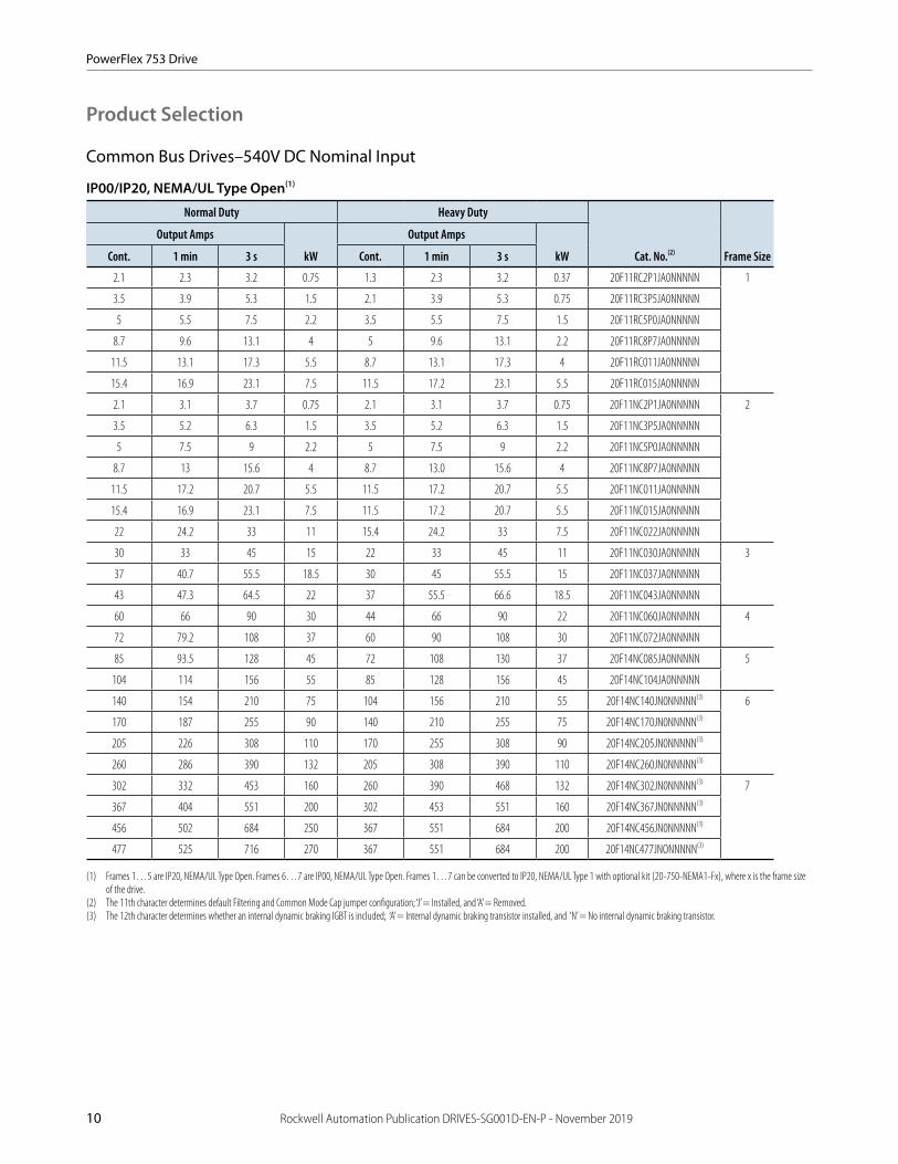
10 Rockwell Automation Publication DRIVES-SG001D-EN-P - November 2019
Product Selection
Common Bus Drives–540V DC Nominal Input
IP00/IP20, NEMA/UL Type Open(1)
Normal Duty Heavy Duty
Cat. No.(2) Frame Size
Output Amps
kW
Output Amps
kWCont. 1 min 3 s Cont. 1 min 3 s
2.1 2.3 3.2 0.75 1.3 2.3 3.2 0.37 20F11RC2P1JA0NNNNN 1
3.5 3.9 5.3 1.5 2.1 3.9 5.3 0.75 20F11RC3P5JA0NNNNN
5 5.5 7.5 2.2 3.5 5.5 7.5 1.5 20F11RC5P0JA0NNNNN
8.7 9.6 13.1 4 5 9.6 13.1 2.2 20F11RC8P7JA0NNNNN
11.5 13.1 17.3 5.5 8.7 13.1 17.3 4 20F11RC011JA0NNNNN
15.4 16.9 23.1 7.5 11.5 17.2 23.1 5.5 20F11RC015JA0NNNNN
2.1 3.1 3.7 0.75 2.1 3.1 3.7 0.75 20F11NC2P1JA0NNNNN 2
3.5 5.2 6.3 1.5 3.5 5.2 6.3 1.5 20F11NC3P5JA0NNNNN
5 7.5 9 2.2 5 7.5 9 2.2 20F11NC5P0JA0NNNNN
8.7 13 15.6 4 8.7 13.0 15.6 4 20F11NC8P7JA0NNNNN
11.5 17.2 20.7 5.5 11.5 17.2 20.7 5.5 20F11NC011JA0NNNNN
15.4 16.9 23.1 7.5 11.5 17.2 20.7 5.5 20F11NC015JA0NNNNN
22 24.2 33 11 15.4 24.2 33 7.5 20F11NC022JA0NNNNN
30 33 45 15 22 33 45 11 20F11NC030JA0NNNNN 3
37 40.7 55.5 18.5 30 45 55.5 15 20F11NC037JA0NNNNN
43 47.3 64.5 22 37 55.5 66.6 18.5 20F11NC043JA0NNNNN
60 66 90 30 44 66 90 22 20F11NC060JA0NNNNN 4
72 79.2 108 37 60 90 108 30 20F11NC072JA0NNNNN
85 93.5 128 45 72 108 130 37 20F14NC085JA0NNNNN 5
104 114 156 55 85 128 156 45 20F14NC104JA0NNNNN
140 154 210 75 104 156 210 55 20F14NC140JN0NNNNN(3) 6
170 187 255 90 140 210 255 75 20F14NC170JN0NNNNN(3)
205 226 308 110 170 255 308 90 20F14NC205JN0NNNNN(3)
260 286 390 132 205 308 390 110 20F14NC260JN0NNNNN(3)
302 332 453 160 260 390 468 132 20F14NC302JN0NNNNN(3) 7
367 404 551 200 302 453 551 160 20F14NC367JN0NNNNN(3)
456 502 684 250 367 551 684 200 20F14NC456JN0NNNNN(3)
477 525 716 270 367 551 684 200 20F14NC477JNONNNNN(3)
(1) Frames 1…5 are IP20, NEMA/UL Type Open. Frames 6…7 are IP00, NEMA/UL Type Open. Frames 1…7 can be converted to IP20, NEMA/UL Type 1 with optional kit (20-750-NEMA1-Fx), where x is the frame size of the drive.
(2) The 11th character determines default Filtering and Common Mode Cap jumper configuration; ‘J’ = Installed, and ‘A’ = Removed.(3) The 12th character determines whether an internal dynamic braking IGBT is included; ‘A’ = Internal dynamic braking transistor installed, and ‘N’ = No internal dynamic braking transistor.

PowerFlex 753 Drive
Rockwell Automation Publication DRIVES-SG001D-EN-P - November 2019 11
Common Bus Drives–540V DC Nominal Input (continued)
IP54, NEMA/UL Type 12
Normal Duty Heavy Duty
Cat. No.(1) Frame Size
Output Amps
kW
Output Amps
kWCont. 1 min 3 s Cont. 1 min 3 s
2.1 3.1 3.7 0.75 2.1 3.1 3.7 0.75 20F11GC2P1JA0NNNNN 2
3.5 5.2 6.3 1.5 3.5 5.2 6.3 1.5 20F11GC3P5JA0NNNNN
5 7.5 9 2.2 5 7.5 9 2.2 20F11GC5P0JA0NNNNN
8.7 13 15.6 4 8.7 13 15.6 4 20F11GC8P7JA0NNNNN
11.5 17.2 20.7 5.5 11.5 17.2 20.7 5.5 20F11GC011JA0NNNNN
15.4 16.9 23.1 7.5 11.5 17.2 20.7 5.5 20F11GC015JA0NNNNN
22 24.2 33 11 15.4 24.2 33 7.5 20F11GC022JA0NNNNN
30 33 45 15 22 33 45 11 20F11GC030JA0NNNNN 3
37 40.7 55.5 18.5 30 45 55.5 15 20F11GC037JA0NNNNN
43 47.3 64.5 22 37 55.5 66.6 18.5 20F11GC043JA0NNNNN
60 66 90 30 44 66 90 22 20F11GC060JA0NNNNN 4
72 79.2 108 37 60 90 108 30 20F14GC072JA0NNNNN 5
85 93.5 128 45 72 108 130 37 20F14GC085JA0NNNNN
104 114 156 55 85 128 156 45 20F14GC104JN0NNNNN(2) 6
140 154 210 75 104 156 210 55 20F14GC140JN0NNNNN(2)
170 187 255 90 140 210 255 75 20F14GC170JN0NNNNN(2)
205 226 308 110 170 255 308 90 20F14GC205JN0NNNNN(2)
260 286 390 132 205 308 390 110 20F14GC260JN0NNNNN(2) 7
302 332 453 160 260 390 468 132 20F14GC302JN0NNNNN(2)
367 404 551 200 302 453 551 160 20F14GC367JN0NNNNN(2)
456 502 684 250 367 551 684 200 20F14GC456JN0NNNNN(2)
(1) The 11th character determines default Filtering and Common Mode Cap jumper configuration; ‘J’ = Installed, and ‘A’ = Removed.(2) The 12th character determines whether an internal dynamic braking IGBT is included; ‘A’ = Internal dynamic braking transistor installed, and ‘N’ = No internal dynamic braking transistor.

PowerFlex 753 Drive
12 Rockwell Automation Publication DRIVES-SG001D-EN-P - November 2019
Common Bus Drives–540V DC Nominal Input (continued)
Flange Mount (Front: IP20, NEMA/UL Type Open; Back/Heatsink: IP66, NEMA/UL Type 4X)
Important: Frame 6…7 IP00, NEMA Type Open drives can be converted to a flange mount drive (back/heatsink: IP66, NEMA/UL Type 4X) with an optional user installed flange kit (kit 20-750-FLNG4-F6 for Frame 6, and kit 20-750-FLNG4-F7 for Frame 7). See page 10 for 540V DC, Frame 6…7 IP00, NEMA Type Open drives.
Normal Duty Heavy Duty
Cat. No.(1) Frame Size
Output Amps
kW
Output Amps
kWCont. 1 min 3 s Cont. 1 min 3 s
2.1 3.1 3.7 0.75 2.1 3.1 3.7 0.75 20F11FC2P1JA0NNNNN 2
3.5 5.2 6.3 1.5 3.5 5.2 6.3 1.5 20F11FC3P5JA0NNNNN
5 7.5 9 2.2 5 7.5 9 2.2 20F11FC5P0JA0NNNNN
8.7 13 15.6 4 8.7 13 15.6 4 20F11FC8P7JA0NNNNN
11.5 17.2 20.7 5.5 11.5 17.2 20.7 5.5 20F11FC011JA0NNNNN
15.4 16.9 23.1 7.5 11.5 17.2 20.7 5.5 20F11FC014JA0NNNNN
22 24.2 33 11 15.4 24.2 33 7.5 20F11FC022JA0NNNNN
30 33 45 15 22 33 45 11 20F11FC030JA0NNNNN 3
37 40.7 55.5 18.5 30 45 55.5 15 20F11FC037JA0NNNNN
43 47.3 64.5 22 37 55.5 66.6 18.5 20F11FC043JA0NNNNN
60 66 90 30 44 66 90 22 20F11FC060JA0NNNNN 4
72 79.2 108 37 60 90 108 30 20F11FC072JA0NNNNN
85 93.5 128 45 72 108 130 37 20F14FC085JA0NNNNN 5
104 114 156 55 85 128 156 45 20F14FC104JA0NNNNN
(1) The 11th character determines default filtering and common mode cap jumper configuration; ‘J’ = Installed, and ‘A’ = Removed.

PowerFlex 753 Drive
Rockwell Automation Publication DRIVES-SG001D-EN-P - November 2019 13
Common Bus Drives–650V DC Nominal Input
IP00/IP20, NEMA/UL Type Open(1)
Normal Duty Heavy Duty
Cat. No.(2) Frame Size
Output Amps
Hp
Output Amps
HpCont. 1 min 3 s Cont. 1 min 3 s
2.1 2.3 3.2 1 1.1 2.3 3.2 0.5 20F11RD2P1JA0NNNNN 1
3.4 3.7 5.1 2 2.8 4.2 5.1 1 20F11RD3P4JA0NNNNN
5 5.5 7.5 3 3.4 5.5 7.5 2 20F11RD5P0JA0NNNNN
8 8.8 12 5 5 8.8 12 3 20F11RD8P0JA0NNNNN
11 12.1 16.5 7.5 8 12.1 16.5 5 20F11RD011JA0NNNNN
14 15.4 21 10 11 16.5 21 7.5 20F11RD014JA0NNNNN
2.1 3.1 3.7 1 2.1 3.1 3.7 1 20F11ND2P1JA0NNNNN 2
3.4 5.1 6.1 2 3.4 5.1 6.1 2 20F11ND3P4JA0NNNNN
5 7.5 9 3 5 7.5 9 3 20F11ND5P0JA0NNNNN
8 12 14.4 5 8 12 14.4 5 20F11ND8P0JA0NNNNN
11 16.5 19.8 7.5 11 16.5 19.8 7.5 20F11ND011JA0NNNNN
14 15.4 21 10 11 16.5 21 7.5 20F11ND014JA0NNNNN
22 24.2 33 15 14 24.2 33 15 20F11ND022JA0NNNNN
27 29.7 40.5 20 22 33 40.5 15 20F11ND027JA0NNNNN 3
34 37.4 51 25 27 40.5 51 20 20F11ND034JA0NNNNN
40 44 60 30 34 51 61.2 25 20F11ND040JA0NNNNN
52 57.2 78 40 40 60 78 30 20F11ND052JA0NNNNN 4
65 71.5 97.5 50 52 78 97.5 40 20F11ND065JA0NNNNN
77 84.7 116 60 65 97.5 116 50 20F14ND077JA0NNNNN 5
96 106 144 75 77 116 144 60 20F14ND096JA0NNNNN
125 138 188 100 96 144 188 75 20F14ND125JN0NNNNN(3) 6
156 172 234 125 125 188 234 100 20F14ND156JN0NNNNN(3)
186 205 279 150 156 234 281 125 20F14ND186JN0NNNNN(3)
248 273 372 200 186 279 372 150 20F14ND248JN0NNNNN(3)
302 332 453 250 248 372 453 200 20F14ND302JN0NNNNN(3) 7
361 397 542 300 302 453 535 250 20F14ND361JN0NNNNN(3)
415 457 623 350 361 542 650 300 20F14ND415JN0NNNNN(3)
477 525 716 400 361 542 650 300 20F14ND477JN0NNNNN(3)
(1) Frames 1…5 are IP20, NEMA/UL Type Open. Frames 6…7 are IP00, NEMA/UL Type Open. Frames 1…7 can be converted to IP20, NEMA/UL Type 1 with optional kit (20-750-NEMA1-Fx), where x is the frame size of the drive.
(2) The 11th character determines default Filtering and Common Mode Cap jumper configuration; ‘J’ = Installed, and ‘A’ = Removed.(3) The 12th character determines whether an internal dynamic braking IGBT is included; ‘A’ = Internal dynamic braking transistor installed, and ‘N’ = No internal dynamic braking transistor.

PowerFlex 753 Drive
14 Rockwell Automation Publication DRIVES-SG001D-EN-P - November 2019
Common Bus Drives–650V DC Nominal Input (continued)
IP54, NEMA/UL Type 12
Normal Duty Heavy Duty
Cat. No.(1) Frame Size
Output Amps
Hp
Output Amps
HpCont. 1 min 3 s Cont. 1 min 3 s
2.1 3.1 3.7 1 2.1 3.1 3.7 1 20F11GD2P1JA0NNNNN 2
3.4 5.1 6.1 2 3.4 5.1 6.1 2 20F11GD3P4JA0NNNNN
5 7.5 9 3 5 7.5 9 3 20F11GD5P0JA0NNNNN
8 12 14.4 5 8 12 14.4 5 20F11GD8P0JA0NNNNN
11 16.5 19.8 7.5 11 16.5 19.8 7.5 20F11GD011JA0NNNNN
14 15.4 21 10 11 16.5 21 7.5 20F11GD014JA0NNNNN
22 24.2 33 15 14 24.2 33 15 20F11GD022JA0NNNNN
27 29.7 40.5 20 22 33 40.5 15 20F11GD027JA0NNNNN 3
34 37.4 51 25 27 40.5 51 20 20F11GD034JA0NNNNN
40 44 60 30 34 51 61.2 25 20F11GD040JA0NNNNN
52 57.2 78 40 40 60 78 30 20F11GD052JA0NNNNN 4
65 71.5 97.5 50 52 78 97.5 40 20F14GD065JA0NNNNN 5
77 84.7 116 60 65 97.5 116 50 20F14GD077JA0NNNNN
96 106 144 75 77 116 144 60 20F14GD096JN0NNNNN(2) 6
125 138 188 100 96 144 188 75 20F14GD125JN0NNNNN(2)
156 172 234 125 125 188 234 100 20F14GD156JN0NNNNN(2)
186 205 279 150 156 234 281 125 20F14GD186JN0NNNNN(2)
248 273 372 200 186 279 372 150 20F14GD248JN0NNNNN(2) 7
302 332 453 250 248 372 453 200 20F14GD302JN0NNNNN(2)
361 397 542 300 302 453 535 250 20F14GD361JN0NNNNN(2)
415 457 623 350 361 542 650 300 20F14GD415JN0NNNNN(2)
(1) The 11th character determines default Filtering and Common Mode Cap jumper configuration; ‘J’ = Installed, and ‘A’ = Removed.(2) The 12th character determines whether an internal dynamic braking IGBT is included; ‘A’ = Internal dynamic braking transistor installed, and ‘N’ = No internal dynamic braking transistor.

PowerFlex 753 Drive
Rockwell Automation Publication DRIVES-SG001D-EN-P - November 2019 15
Common Bus Drives–650V DC Nominal Input (continued)
Flange Mount (Front: IP20, NEMA/UL Type Open; Back/Heatsink: IP66, NEMA/UL Type 4X)
Important: Frame 6…7 IP00, NEMA Type Open drives can be converted to a flange mount drive (back/heatsink: IP66, NEMA/UL Type 4X) with an optional user installed flange kit (kit 20-750-FLNG4-F6 for Frame 6, and kit 20-750-FLNG4-F7 for Frame 7). See page 13 for 650V DC, Frame 6…7 IP00, NEMA Type Open drives.
Normal Duty Heavy Duty
Cat. No.(1) Frame Size
Output Amps
Hp
Output Amps
HpCont. 1 min 3 s Cont. 1 min 3 s
2.1 3.1 3.7 1 2.1 3.1 3.7 1 20F11FD2P1JA0NNNNN 2
3.4 5.1 6.1 2 3.4 5.1 6.1 2 20F11FD3P4JA0NNNNN
5 7.5 9 3 5 7.5 9.0 3 20F11FD5P0JA0NNNNN
8 12 14.4 5 8 12 14.4 5 20F11FD8P0JA0NNNNN
11 16.5 19.8 7.5 11 16.5 19.8 7.5 20F11FD011JA0NNNNN
14 15.4 21 10 11 16.5 21 7.5 20F11FD014JA0NNNNN
22 24.2 33 15 14 24.2 33 15 20F11FD022JA0NNNNN
27 29.7 40.5 20 22 33 40.5 15 20F11FD027JA0NNNNN 3
34 37.4 51 25 27 40.5 51 20 20F11FD034JA0NNNNN
40 44 60 30 34 51 61.2 25 20F11FD040JA0NNNNN
52 57.2 78 40 40 60 78 30 20F11FD052JA0NNNNN 4
65 71.5 97.5 50 52 78 97.5 40 20F11FD065JA0NNNNN
77 84.7 116 60 65 97.5 116 50 20F14FD077JA0NNNNN 5
96 106 144 75 77 116 144 60 20F14FD096JA0NNNNN
(1) The 11th character determines default Filtering and Common Mode Cap jumper configuration; ‘J’ = Installed, and ‘A’ = Removed.

PowerFlex 753 Drive
16 Rockwell Automation Publication DRIVES-SG001D-EN-P - November 2019
Common Bus Drives–810V DC Nominal Input
IP00/IP20, NEMA/UL Type Open(1)
Important: At 810V DC, PowerFlex 750-series Frames 3…5 drives cannot be used on the same common DC bus as 810/932V DC PowerFlex 750-series Frames 6…10 drives. For more details, contact your local Rockwell Automation sales office or your Allen-Bradley distributor.
Normal Duty Heavy Duty
Cat. No.(2) Frame Size
Output Amps
Hp
Output Amps
HpCont. 1 min 3 s Cont. 1 min 3 s
1.7 1.9 2.6 1 1.7 1.4 2.6 1 20F11NE1P7JA0NNNNN 3
2.7 3 4.1 2 1.7 2.6 4.1 1 20F11NE2P7JA0NNNNN
3.9 4.29 5.85 3 2.7 4.1 5.9 2 20F11NE3P9JA0NNNNN
6.1 6.7 9.2 5 3.9 5.9 9.2 3 20F11NE6P1JA0NNNNN
9 9.9 13.5 7.5 6.1 9.2 13.5 5 20F11NE9P0JA0NNNNN
11 12.1 16.5 10 9 13.5 16.5 7.5 20F11NE011JA0NNNNN
17 18.7 25.5 15 11 16.5 25.5 10 20F11NE017JA0NNNNN
22 24.2 33 20 17 25.5 33 15 20F11NE022JA0NNNNN
27 29.7 40.5 25 22 33 40.5 20 20F11NE027JA0NNNNN 4
32 35.2 48 30 27 40.5 48.6 25 20F11NE032JA0NNNNN
41 45.1 61.5 40 32 48 61.5 30 20F14NE041JA0NNNNN 5
52 57.2 78 50 41 61.5 78 40 20F14NE052JA0NNNNN
12 13.2 18 10 9.1 13.7 18 7.5 20F14NE012JN0NNNNN(3) 6
18 19.8 27 15 12 18 27 10 20F14NE018JN0NNNNN(3)
23 25.3 34.5 20 18 27 34.5 15 20F14NE023JN0NNNNN(3)
24 26.4 36 20 22 33 39.6 20 20F14NE024JN0NNNNN(3)
28 30.8 42 25 23 34.5 42 20 20F14NE028JN0NNNNN(3)
33 36.3 49.5 30 28 42 50.4 25 20F14NE033JN0NNNNN(3)
42 46.2 63 40 33 49.5 63 30 20F14NE042JN0NNNNN(3)
53 58 80 50 42 63 80 40 20F14NE053JN0NNNNN(3)
63 69 95 60 52 78 95 50 20F14NE063JN0NNNNN(3)
77 85 116 75 63 95 116 50 20F14NE077JN0NNNNN(3)
99 109 149 100 77 116 149 60 20F14NE099JN0NNNNN(3)
125 138 188 125 99 149 188 75 20F14NE125JN0NNNNN(3)
144 158 216 150 125 188 225 100 20F14NE144JN0NNNNN(3)
192 211 288 200 144 216 288 125 20F14NE192JN0NNNNN(3) 7
242 266 363 250 192 288 363 150 20F14NE242JN0NNNNN(3)
289 318 434 300 242 363 436 200 20F14NE289JN0NNNNN(3)
(1) Frames 3…5 are IP20, NEMA/UL Type Open. Frames 6…7 are IP00, NEMA/UL Type Open. Frames 3…7 can be converted to IP20, NEMA/UL Type 1 with optional kit (20-750-NEMA1-Fx), where x is the frame size of the drive.
(2) The 11th character determines default Filtering and Common Mode Cap jumper configuration; ‘J’ = Installed, and ‘A’ = Removed.(3) The 12th character determines whether an internal dynamic braking IGBT is included; ‘A’ = Internal dynamic braking transistor installed, and ‘N’ = No internal dynamic braking transistor.

PowerFlex 753 Drive
Rockwell Automation Publication DRIVES-SG001D-EN-P - November 2019 17
Common Bus Drives–810V DC Nominal Input (continued)
IP54, NEMA/UL Type 12
Important: At 810V DC, PowerFlex 750-series Frames 3…5 drives cannot be used on the same common DC bus as 810/932V DC PowerFlex 750-series Frames 6…10 drives. For more details, contact your local Rockwell Automation sales office or your Allen-Bradley distributor.
Normal Duty Heavy Duty
Cat. No.(1) Frame Size
Output Amps
Hp
Output Amps
HpCont. 1 min 3 s Cont. 1 min 3 s
1.7 1.9 2.6 1 1.7 1.4 2.6 1 20F11GE1P7JA0NNNNN 3
2.7 3 4.1 2 1.7 2.6 4.1 1 20F11GE2P7JA0NNNNN
3.9 4.29 5.85 3 2.7 4.1 5.9 2 20F11GE3P9JA0NNNNN
6.1 6.7 9.2 5 3.9 5.9 9.2 3 20F11GE6P1JA0NNNNN
9 9.9 13.5 7.5 6.1 9.2 13.5 5 20F11GE9P0JA0NNNNN
11 12.1 16.5 10 9 13.5 16.5 7.5 20F11GE011JA0NNNNN
17 18.7 25.5 15 11 16.5 25.5 10 20F11GE017JA0NNNNN
22 24.2 33 20 17 25.5 33 15 20F11GE022JA0NNNNN
27 29.7 40.5 25 22 33 40.5 20 20F11GE027JA0NNNNN 4
32 35.2 48 30 27 40.5 48.6 25 20F11GE032JA0NNNNN
41 45.1 61.5 40 32 48 61.5 30 20F14GE041JA0NNNNN 5
12 13.2 18 10 9.1 13.7 18 7.5 20F14GE012JN0NNNNN(2) 6
18 19.8 27 15 12 18 27 10 20F14GE018JN0NNNNN(2)
23 25.3 34.5 20 18 27 34.5 15 20F14GE023JN0NNNNN(2)
24 26.4 36 20 22 33 39.6 20 20F14GE024JN0NNNNN(2)
28 30.8 42 25 23 34.5 42 20 20F14GE028JN0NNNNN(2)
33 36.3 49.5 30 28 42 50.4 25 20F14GE033JN0NNNNN(2)
42 46.2 63 40 33 49.5 63 30 20F14GE042JN0NNNNN(2)
53 58 80 50 42 63 80 40 20F14GE053JN0NNNNN(2)
63 69 95 60 52 78 95 50 20F14GE063JN0NNNNN(2)
77 85 116 75 63 95 116 50 20F14GE077JN0NNNNN(2)
99 109 149 100 77 116 149 60 20F14GE099JN0NNNNN(2)
125 138 188 125 99 149 188 75 20F14GE125JN0NNNNN(2)
144 158 216 150 125 188 225 100 20F14GE144JN0NNNNN(2)
192 211 288 200 144 216 288 125 20F14GE192JN0NNNNN(2) 7
242 266 363 250 192 288 363 150 20F14GE242JN0NNNNN(2)
289 318 434 300 242 363 436 200 20F14GE289JN0NNNNN(2)
(1) The 11th character determines default Filtering and Common Mode Cap jumper configuration; ‘J’ = Installed, and ‘A’ = Removed.(2) The 12th character determines whether an internal dynamic braking IGBT is included; ‘A’ = Internal dynamic braking transistor installed, and ‘N’ = No internal dynamic braking transistor.

PowerFlex 753 Drive
18 Rockwell Automation Publication DRIVES-SG001D-EN-P - November 2019
Common Bus Drives–810V DC Nominal Input (continued)
Flange Mount (Front: IP20, NEMA/UL Type Open; Back/Heatsink: IP66, NEMA/UL Type 4X)
Important: At 810V DC, PowerFlex 750-series Frames 3…5 drives cannot be used on the same common DC bus as 810/932V DC PowerFlex 750-series Frames 6…10 drives. For more details, contact your local Rockwell Automation sales office or your Allen-Bradley distributor.
Important: Frame 6…7 IP00, NEMA Type Open drives can be converted to a flange mount drive (back/heatsink: IP66, NEMA/UL Type 4X) with an optional user installed flange kit (kit 20-750-FLNG4-F6 for Frame 6, and kit 20-750-FLNG4-F7 for Frame 7). See page 16 for 810V DC, Frame 6…7 IP00, NEMA Type Open drives.
Normal Duty Heavy Duty
Cat. No.(1) Frame Size
Output Amps
Hp
Output Amps
HpCont. 1 min 3 s Cont. 1 min 3 s
1.7 1.9 2.6 1 1.7 1.4 2.6 1 20F11FE1P7JA0NNNNN 3
2.7 3 4.1 2 1.7 2.6 4.1 1 20F11FE2P7JA0NNNNN
3.9 4.29 5.85 3 2.7 4.1 5.9 2 20F11FE3P9JA0NNNNN
6.1 6.7 9.2 5 3.9 5.9 9.2 3 20F11FE6P1JA0NNNNN
9 9.9 13.5 7.5 6.1 9.2 13.5 5 20F11FE9P0JA0NNNNN
11 12.1 16.5 10 9 13.5 16.5 7.5 20F11FE011JA0NNNNN
17 18.7 25.5 15 11 16.5 25.5 10 20F11FE017JA0NNNNN
22 24.2 33 20 17 25.5 33 15 20F11FE022JA0NNNNN
27 29.7 40.5 25 22 33 40.5 20 20F11FE027JA0NNNNN 4
32 35.2 48 30 27 40.5 48.6 25 20F11FE032JA0NNNNN
41 45.1 61.5 40 32 48 61.5 30 20F14FE041JA0NNNNN 5
52 57.2 78.0 50 41 61.5 78 40 20F14FE052JA0NNNNN
(1) The 11th character determines default Filtering and Common Mode Cap jumper configuration; ‘J’ = Installed, and ‘A’ = Removed.
PowerFlex 753 Drive
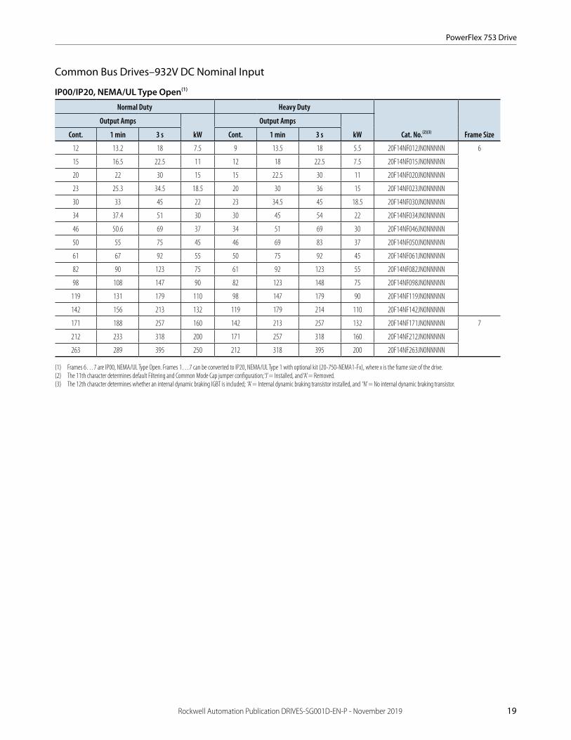
Rockwell Automation Publication DRIVES-SG001D-EN-P - November 2019 19
Common Bus Drives–932V DC Nominal Input
IP00/IP20, NEMA/UL Type Open(1)
Normal Duty Heavy Duty
Cat. No.(2)(3) Frame Size
Output Amps
kW
Output Amps
kWCont. 1 min 3 s Cont. 1 min 3 s
12 13.2 18 7.5 9 13.5 18 5.5 20F14NF012JN0NNNNN 6
15 16.5 22.5 11 12 18 22.5 7.5 20F14NF015JN0NNNNN
20 22 30 15 15 22.5 30 11 20F14NF020JN0NNNNN
23 25.3 34.5 18.5 20 30 36 15 20F14NF023JN0NNNNN
30 33 45 22 23 34.5 45 18.5 20F14NF030JN0NNNNN
34 37.4 51 30 30 45 54 22 20F14NF034JN0NNNNN
46 50.6 69 37 34 51 69 30 20F14NF046JN0NNNNN
50 55 75 45 46 69 83 37 20F14NF050JN0NNNNN
61 67 92 55 50 75 92 45 20F14NF061JN0NNNNN
82 90 123 75 61 92 123 55 20F14NF082JN0NNNNN
98 108 147 90 82 123 148 75 20F14NF098JN0NNNNN
119 131 179 110 98 147 179 90 20F14NF119JN0NNNNN
142 156 213 132 119 179 214 110 20F14NF142JN0NNNNN
171 188 257 160 142 213 257 132 20F14NF171JN0NNNNN 7
212 233 318 200 171 257 318 160 20F14NF212JN0NNNNN
263 289 395 250 212 318 395 200 20F14NF263JN0NNNNN
(1) Frames 6…7 are IP00, NEMA/UL Type Open. Frames 1…7 can be converted to IP20, NEMA/UL Type 1 with optional kit (20-750-NEMA1-Fx), where x is the frame size of the drive.(2) The 11th character determines default Filtering and Common Mode Cap jumper configuration; ‘J’ = Installed, and ‘A’ = Removed.(3) The 12th character determines whether an internal dynamic braking IGBT is included; ‘A’ = Internal dynamic braking transistor installed, and ‘N’ = No internal dynamic braking transistor.

PowerFlex 753 Drive
20 Rockwell Automation Publication DRIVES-SG001D-EN-P - November 2019
Common Bus Drives–932V DC Nominal Input (continued)
IP54, NEMA/UL Type 12
Normal Duty Heavy Duty
Cat. No.(2)(3) Frame Size
Outputs Amp
kW
Output Amps
kWCont. 1 min 3 s Cont. 1 min 3 s
12 13.2 18 7.5 9 13.5 18 5.5 20F14GF012JN0NNNNN 6
15 16.5 22.5 11 12 18 22.5 7.5 20F14GF015JN0NNNNN
20 22 30 15 15 22.5 30 11 20F14GF020JN0NNNNN
23 25.3 34.5 18.5 20 30 36 15 20F14GF023JN0NNNNN
30 33 45 22 23 34.5 45 18.5 20F14GF030JN0NNNNN
34 37.4 51 30 30 45 54 22 20F14GF034JN0NNNNN
46 50.6 69 37 34 51 69 30 20F14GF046JN0NNNNN
50 55 75 45 46 69 83 37 20F14GF050JN0NNNNN
61 67 92 55 50 75 92 45 20F14GF061JN0NNNNN
82 90 123 75 61 92 123 55 20F14GF082JN0NNNNN
98 108 147 90 82 123 148 75 20F14GF098JN0NNNNN
119 131 179 110 98 147 179 90 20F14GF119JN0NNNNN
142 156 213 132 119 179 214 110 20F14GF142JN0NNNNN
171 188 257 160 142 213 257 132 20F14GF171JN0NNNNN 7
212 233 318 200 171 257 318 160 20F14GF212JN0NNNNN
263 289 395 250 212 318 395 200 20F14GF263JN0NNNNN
(1) The 11th character determines default Filtering and Common Mode Cap jumper configuration; ‘J’ = Installed, and ‘A’ = Removed.(2) The 12th character determines whether an internal dynamic braking IGBT is included; ‘A’ = Internal dynamic braking transistor installed, and ‘N’ = No internal dynamic braking transistor.
Flange Mount (Front: IP20, NEMA/UL Type Open; Back/Heatsink: IP66, NEMA/UL Type 4X)
Important: Frame 6…7 IP00, NEMA Type Open drives can be converted to a flange mount drive (Back/Heatsink: IP66, NEMA/UL Type 4X) with an optional user installed flange kit (20-750-FLNG4-F6 for Frame 6, and 20-750-FLNG4-F7 for Frame 7).
See page 19 for 932V DC, Frame 6…7 IP00, NEMA Type Open drives.

PowerFlex 753 Drive
Rockwell Automation Publication DRIVES-SG001D-EN-P - November 2019 21
Approximate Dimensions and WeightsDimensions are in mm (in.) - weights are in kg (lb)
IP00/IP20, NEMA/UL Type Open
Frame H W D Weight(1)
1 400.5 (15.77) 110 (4.33) 211 (8.31) 6 (12.75)
2 424.2 (16.7) 134.5 (5.3) 212 (8.35) 7.8 (17.2)
3 454 (17.87) 190 (7.48) 11.8 (26.1)
4 474 (18.66) 222 (8.74) 13.6 (30)
5 550 (21.65) 270 (10.63) 20.4 (45)
6 665.5 (26.2) 308 (12.13) 346.4 (13.64) 38.6 (85)
7 881.5 (34.7) 430 (16.93) 349.6 (13.76) 72.6…108.9 (160…240)
(1) Weights are approximate. Refer to 750-TD001, the PowerFlex 750-Series Technical Data, for detailed weight information.
IP54, NEMA/UL Type 12
Frame H W D Weight(1)
2 543.2 (21.39) 215.3 (8.48) 222.2 (8.75) 8 (17)
3 551 (21.69) 268 (10.55) 220.1 (8.67) 12 (26)
4 571 (22.48) 300 (11.81) 14 (30)
5 647 (25.47) 348.0 (13.7) 20 (45)
6 1298.3 (51.11) 609.4 (24) 464.7 (18.3) 91 (200)
7 1614 (63.54) 162 (357)
(1) Weights are approximate. Refer to 750-TD001, the PowerFlex 750-Series Technical Data, for detailed weight information.
Flange Mount
Frame H W D1 D2 Weight(1)
2 481.8 (18.97) 206.2 (8.12) 148.3 (5.84) 63.7 (2.51) 8 (17)
3 515 (20.28) 260 (10.24) 127.4 (5.02) 84.6 (3.33) 12 (26)
4 535 (21.06) 292 (11.5) 14 (30)
5 611 (24.06) 340 (13.39) 20 (45)
6 665.5 (26.2) 308 (12.13) 208.4 (8.2) 138 (5.43) 38 (84)
7 875 (34.45) 430 (16.93) 96 (212)
(1) Weights are approximate. Refer to 750-TD001, the PowerFlex 750-Series Technical Data, for detailed weight information.
22 Rockwell Automation Publication DRIVES-SG001D-EN-P - November 2019
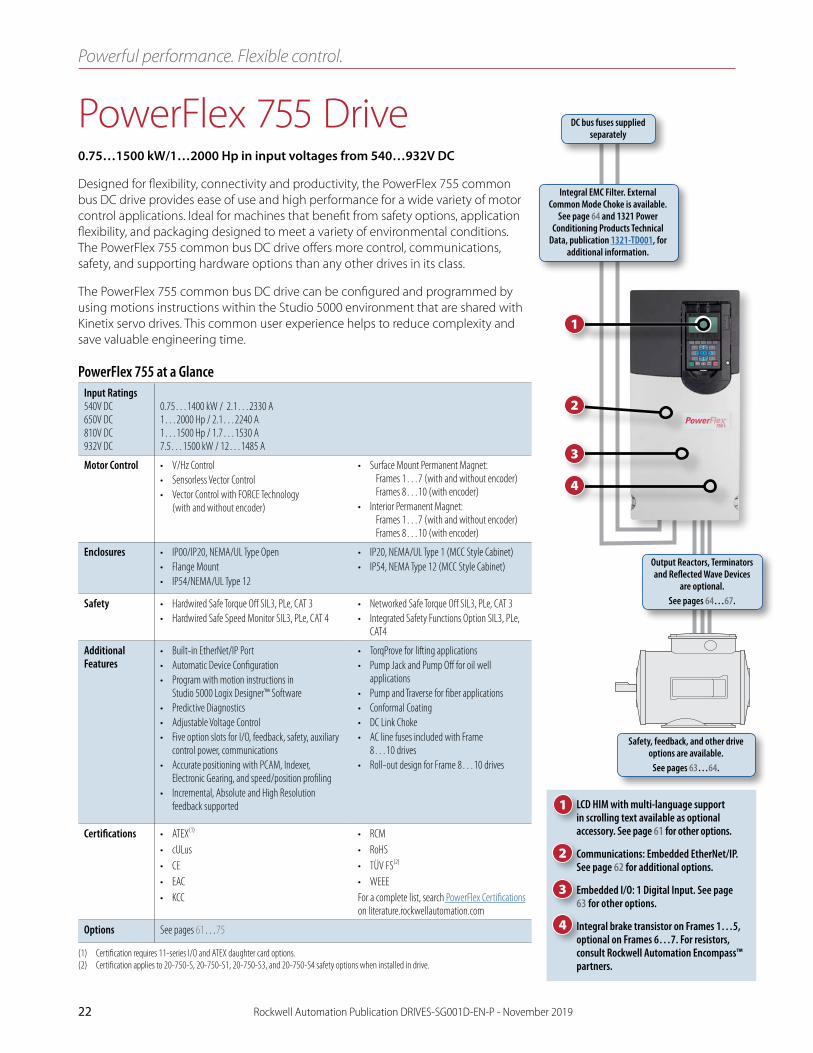
PowerFlex 755 Drive0 .75…1500 kW/1…2000 Hp in input voltages from 540…932V DC
Designed for flexibility, connectivity and productivity, the PowerFlex 755 common bus DC drive provides ease of use and high performance for a wide variety of motor control applications. Ideal for machines that benefit from safety options, application flexibility, and packaging designed to meet a variety of environmental conditions. The PowerFlex 755 common bus DC drive offers more control, communications, safety, and supporting hardware options than any other drives in its class.
The PowerFlex 755 common bus DC drive can be configured and programmed by using motions instructions within the Studio 5000 environment that are shared with Kinetix servo drives. This common user experience helps to reduce complexity and save valuable engineering time.
Powerful performance. Flexible control.
Input Ratings540V DC650V DC 810V DC 932V DC
0.75…1400 kW / 2.1…2330 A 1…2000 Hp / 2.1…2240 A 1…1500 Hp / 1.7…1530 A 7.5…1500 kW / 12…1485 A
Motor Control • V/Hz Control• Sensorless Vector Control• Vector Control with FORCE Technology
(with and without encoder)
• Surface Mount Permanent Magnet: Frames 1…7 (with and without encoder) Frames 8…10 (with encoder)
• Interior Permanent Magnet: Frames 1…7 (with and without encoder) Frames 8…10 (with encoder)
Enclosures • IP00/IP20, NEMA/UL Type Open• Flange Mount• IP54/NEMA/UL Type 12
• IP20, NEMA/UL Type 1 (MCC Style Cabinet)• IP54, NEMA Type 12 (MCC Style Cabinet)
Safety • Hardwired Safe Torque Off SIL3, PLe, CAT 3• Hardwired Safe Speed Monitor SIL3, PLe, CAT 4
• Networked Safe Torque Off SIL3, PLe, CAT 3• Integrated Safety Functions Option SIL3, PLe,
CAT4
Additional Features
• Built-in EtherNet/IP Port• Automatic Device Configuration• Program with motion instructions in
Studio 5000 Logix Designer™ Software• Predictive Diagnostics• Adjustable Voltage Control• Five option slots for I/O, feedback, safety, auxiliary
control power, communications• Accurate positioning with PCAM, Indexer,
Electronic Gearing, and speed/position profiling• Incremental, Absolute and High Resolution
feedback supported
• TorqProve for lifting applications• Pump Jack and Pump Off for oil well
applications• Pump and Traverse for fiber applications• Conformal Coating• DC Link Choke• AC line fuses included with Frame
8…10 drives• Roll-out design for Frame 8…10 drives
Certifications • ATEX(1)
• cULus• CE• EAC• KCC
• RCM• RoHS• TÜV FS(2)
• WEEEFor a complete list, search PowerFlex Certifications on literature.rockwellautomation.com
Options See pages 61…75
(1) Certification requires 11-series I/O and ATEX daughter card options.(2) Certification applies to 20-750-S, 20-750-S1, 20-750-S3, and 20-750-S4 safety options when installed in drive.
PowerFlex 755 at a Glance
DC bus fuses supplied separately
Integral EMC Filter. External Common Mode Choke is available.
See page 64 and 1321 Power Conditioning Products Technical
Data, publication 1321-TD001, for additional information.
Output Reactors, Terminators and Reflected Wave Devices
are optional.See pages 64…67.
Safety, feedback, and other drive options are available.
See pages 63…64.
1
2
3
4
LCD HIM with multi-language support in scrolling text available as optional accessory. See page 61 for other options.
Communications: Embedded EtherNet/IP. See page 62 for additional options.
Embedded I/O: 1 Digital Input. See page 63 for other options.
Integral brake transistor on Frames 1…5, optional on Frames 6…7. For resistors, consult Rockwell Automation Encompass™ partners.
1
2
3
4

PowerFlex 755 Drive
Rockwell Automation Publication DRIVES-SG001D-EN-P - November 2019 23
PowerFlex 755 Wall Mount DrivesPowerFlex 755 wall mount drives have a power range from 0.75 kW / 1 Hp to 270 kW / 400 Hp and are available in several factory and field installable enclosure options to meet most environmental requirements.
The standard enclosure is optimized for cabinet installation and rated at IP00/IP20, NEMA/UL Type Open. Wall mount drives can be converted to IP20, NEMA/UL Type 1 with an optional kit containing a debris hood and conduit plate. A factory enclosure option is also available with extra protection (IP54, NEMA Type 12) for harsh environments.
Flange mount drives are available via a factory option (Frames 1…5) or field installable kits (Frames 6…7) and are designed to reduce panel cooling requirements by mounting the drive heatsink outside the cabinet.
A DC link choke is included on all frames and internal brake transistor is standard on Frames 1…5 and optional on Frames 6…7.
PowerFlex 755 Floor Mount DrivesPowerFlex 755 floor mount drives have a power range from 200 kW / 250 Hp to 1400 kW / 2000 Hp, and offer multiple duty ratings to provide flexibility for different application requirements. One drive can provide three different motor current ratings. For example a 480 A drive can run a 400 Hp motor in light duty, a 350 Hp motor in normal duty, and a 300 Hp motor in heavy duty.
• Light Duty = 110% of motor rated current for 60 seconds• Normal Duty = 110% of motor rated current for 60 seconds/150% of motor rated current for 3 seconds• Heavy Duty = 150% of motor rated current for 60 seconds/180% of motor rated current for 3 seconds
Other power options from the factory include disconnect, reactor, contactor, integrated MCC bus for direct connection to CENTERLINE® MCC, auxiliary transformer or wiring bay.
IP20, NEMA Type 1 Common Bus Drive (2500 MCC Style Cabinet) (Frame 9 shown)
Includes: Integrated fuses, roll-out design, sealed air channel, exhaust hood, and control/protection devices.
Roll-out Design (Frame 8 shown)
A roll-out cart is required for Frame 8…10 drives and Frame 9…10 optional bay chassis. The cart has an adjustable Curb Height of 0…182 mm (0…7.2 in.) and
curb offset/reach of 0…114 mm (0…4.5 in.). See page 64 for ordering information.

PowerFlex 755 Drive
24 Rockwell Automation Publication DRIVES-SG001D-EN-P - November 2019
Additional InformationPowerFlex 750-Series Brochure, publication 750-BR001 PowerFlex 750-Series Technical Data, publication 750-TD001PowerFlex 750-Series Quick Start Guide, publication 750-QS001
Catalog Number Explanation
21G 1 4 B D 248 J A 0 N N N N N - ND - P24 - P30…
Filtering and
Common ModeCapacitor
Configuration
VoltageRating
Rating BrakeIGBT
Cabinet Options (21G)DoorMounted
HIM(Frames
8…10 only)
Input Type
Code
1
4
Description
AC input with precharge and DC terminals
DC input with precharge
Enclosure Type*
Code
B
L
Description
600 mm deep, IP20/NEMA 1, standard color (RAL 7032)
800 mm deep, IP20/NEMA 1, standard color (RAL 7032)
P
W
800 mm deep, IP20/NEMA 1, with Motor Control Center (MCC) power bus option, standard color (RAL 7032)
800 mm deep, IP20/NEMA 1, with MCC power bus option, CENTERLINE 2100 gray (ASA49)J
K
800 mm deep, IP54/NEMA 12, standard color (RAL 7032)
800 mm deep, IP54/NEMA 12, with MCC power bus option, standard color (RAL 7032)
Y 800 mm deep, IP54/NEMA 12, with MCC power bus option, CENTERLINE 2100 gray (ASA49)
* Frames 9 and 10 are only available in Code P or W Enclosure Types.

PowerFlex 755 Drive
Rockwell Automation Publication DRIVES-SG001D-EN-P - November 2019 25
Product Selection
Common Bus Drives–540V DC Nominal Input
IP00/IP20, NEMA/UL Type Open(1)
Light Duty(2) Normal Duty Heavy Duty
Cat. No.(3)Frame
Size
Output Amps
kW
Output Amps
kW
Output Amps
kWCont. 1 min Cont. 1 min 3 s Cont. 1 min 3 s
— — — 2.1 2.3 3.2 0.75 1.3 2.3 3.2 0.37 20G11RC2P1JA0NNNNN 1
3.5 3.9 5.3 1.5 2.1 3.9 5.3 0.75 20G11RC3P5JA0NNNNN
5 5.5 7.5 2.2 3.5 5.5 7.5 1.5 20G11RC5P0JA0NNNNN
8.7 9.6 13.1 4 5 9.6 13.1 2.2 20G11RC8P7JA0NNNNN
11.5 13.1 17.3 5.5 8.7 13.1 17.3 4 20G11RC011JA0NNNNN
15.4 16.9 23.1 7.5 11.5 17.2 23.1 5.5 20G11RC015JA0NNNNN
2.1 3.1 3.7 0.75 2.1 3.1 3.7 0.75 20G11NC2P1JA0NNNNN 2
3.5 5.2 6.3 1.5 3.5 5.2 6.3 1.5 20G11NC3P5JA0NNNNN
5 7.5 9 2.2 5 7.5 9 2.2 20G11NC5P0JA0NNNNN
8.7 13 15.6 4 8.7 13 15.6 4 20G11NC8P7JA0NNNNN
11.5 17.2 20.7 5.5 11.5 17.2 20.7 5.5 20G11NC011JA0NNNNN
15.4 16.9 23.1 7.5 11.5 17.2 23.1 5.5 20G11NC015JA0NNNNN
22 24.2 33 11 15.4 24.2 33 7.5 20G11NC022JA0NNNNN
30 33 45 15 22 33 45 11 20G11NC030JA0NNNNN 3
37 40.7 55.5 18.5 30 45 55.5 15 20G11NC037JA0NNNNN
43 47.3 64.5 22 37 55.5 66.6 18.5 20G11NC043JA0NNNNN
60 66 90 30 44 66 90 22 20G11NC060JA0NNNNN 4
72 79.2 108 37 60 90 108 30 20G11NC072JA0NNNNN
85 93.5 128 45 72 108 130 37 20G14NC085JA0NNNNN 5
104 114 156 55 85 128 156 45 20G14NC104JA0NNNNN
140 154 210 75 104 156 210 55 20G14NC140JN0NNNNN (4) 6
170 187 255 90 140 210 255 75 20G14NC170JN0NNNNN (4)
205 226 308 110 170 255 308 90 20G14NC205JN0NNNNN (4)
260 286 390 132 205 308 390 110 20G14NC260JN0NNNNN (4)
302 332 453 160 260 390 468 132 20G14NC302JN0NNNNN (4) 7
367 404 551 200 302 453 551 160 20G14NC367JN0NNNNN (4)
456 502 684 250 367 551 684 200 20G14NC456JN0NNNNN (4)
477 525 716 270 367 551 684 200 20G14NC477JNONNNNN(4)
(1) Frames 1…5 are IP20, NEMA/UL Type Open. Frames 6…7 are IP00, NEMA/UL Type Open. Frames 8…10 are IP20, NEMA/UL Type 1. Frames 1…7 can be converted to IP20, NEMA/UL Type 1 with optional kit (20-750-NEMA1-Fx), where x is the frame size of the drive.
(2) Light Duty rating available only on Frame 8…10 drives. Light duty allows 110% overload for 1 minute, and does not have a 3 second overload rating.(3) The 11th character determines default Filtering and Common Mode Cap jumper configuration; “J” = Installed, and “A” = Removed.(4) The 12th character determines whether an internal dynamic braking IGBT is included; “A” = Internal dynamic braking transistor installed, and “N” = No internal dynamic braking transistor.
(table continues on next page)

PowerFlex 755 Drive
26 Rockwell Automation Publication DRIVES-SG001D-EN-P - November 2019
Common Bus Drives–540V DC Nominal Input (continued)
IP00/IP20, NEMA/UL Type Open (continued)(1)
Light Duty(2) Normal Duty Heavy Duty
Base Drive Cat. No.(3)(4)Frame
Size
Output Amps
kW
Output Amps
kW
Output Amps
kWCont. 1 min Cont. 1 min 3 s Cont. 1 min 3 s
540 594 315 460 506 690 250 385 578 693 200 21G14*C460JN0NNNNN 8(6)
585 644 315 540 594 810 315 456 684 821 250 21G14*C540JN0NNNNN
612 673 355 567 624 851 315 472 708 850 250 21G14*C567JN0NNNNN
750 825 400 650 715 975 355 540 810 972 315 21G14*C650JN0NNNNN
796 876 450 750 825 1125 400 585 878 1053 315 21G14*C750JN0NNNNN
832 915 450 770 847 1155 400 642 963 1156 355 21G14*C770JN0NNNNN
1040 1144 560 910 1001 1365 500 750 1125 1350 400 21G14*C910JN0NNNNN 9(6)
1090 1199 630 1040 1144 1560 560 880 1320 1584 500 21G14*C1K0JN0NNNNN
1175 1293 710 1090 1199 1635 630 910 1365 1638 500 21G14*C1K1JN0NNNNN
1465 1612 800 1175 1293 1763 710 1040 1560 1872 560 21G14*C1K2JN0NNNNN
1480 1628 850 1465 1612 2198 800 1090 1635 1962 630 21G14*C1K4JN0NNNNN
1600 1760 900 1480 1628 2220 850 1175 1763 2115 710 21G14*C1K5JN0NNNNN
1715 1887 1000 1590 1749 2385 900 1325 1988 2385 710 21G14*C1K6JN0NNNNN 10(6)
2330 2563 1400 2150 2365 3225 1250 1800 2700 3240 1000 21G14*C2K1JN0NNNNN
(1) Frames 1…5 are IP20, NEMA/UL Type Open. Frames 6…7 are IP00, NEMA/UL Type Open. Frames 8…10 are IP20, NEMA/UL Type 1. Frames 1…7 can be converted to IP20, NEMA/UL Type 1 with optional kit (20-750-NEMA1-Fx), where x is the frame size of the drive.
(2) Light Duty rating only available on Frame 8…10 drives. Light Duty allows 110% overload for 1 minute, and does not have a 3 second overload rating.(3) The 6th character (designated by an * in this table) determines the enclosure type. Refer to the Enclosure Type table in the Catalog Number Explanation on page 24.(4) The 11th character determines default Filtering and Common Mode Cap jumper configuration; “J” = Installed, and “A” = Removed.(5) The 12th character determines whether an internal dynamic braking IGBT is included; “A” = Internal dynamic braking transistor installed, and “N” = No internal dynamic braking transistor.(6) A roll-out cart is required with Frame 8…10 drives to assist with power wiring and cabinet mounting. Refer to page 64.

PowerFlex 755 Drive
Rockwell Automation Publication DRIVES-SG001D-EN-P - November 2019 27
Common Bus Drives–540V DC Nominal Input (continued)
IP54, NEMA/UL Type 12
Light Duty(1) Normal Duty Heavy Duty
Cat. No.(2) Frame
Size
Output Amps
kW
Output Amps
kW
Output Amps
kWCont. 1 min Cont. 1 min 3 s Cont. 1 min 3 s
— — — 2.1 3.1 3.7 0.75 2.1 3.1 3.7 0.75 20G11GC2P1JA0NNNNN 2
3.5 5.2 6.3 1.5 3.5 5.2 6.3 1.5 20G11GC3P5JA0NNNNN
5 7.5 9 2.2 5 7.5 9.0 2.2 20G11GC5P0JA0NNNNN
8.7 13 15.6 4 8.7 13 15.6 4 20G11GC8P7JA0NNNNN
11.5 17.2 20.7 5.5 11.5 17.2 20.7 5.5 20G11GC011JA0NNNNN
15.4 16.9 23.1 7.5 11.5 17.2 23.1 5.5 20G11GC015JA0NNNNN
22 24.2 33 11 15.4 24.2 33 7.5 20G11GC022JA0NNNNN
30 33 45 15 22 33 45 11 20G11GC030JA0NNNNN 3
37 40.7 55.5 18.5 30 45 55.5 15 20G11GC037JA0NNNNN
43 47.3 64.5 22 37 55.5 66.6 18.5 20G11GC043JA0NNNNN
60 66 90 30 44 66 90 22 20G11GC060JA0NNNNN 4
72 79.2 108 37 60 90 108 30 20G14GC072JA0NNNNN 5
85 93.5 128 45 72 108 130 37 20G14GC085JA0NNNNN
104 114 156 55 85 128 156 45 20G14GC104JN0NNNNN(4) 6
140 154 210 75 104 156 210 55 20G14GC140JN0NNNNN(4)
170 187 255 90 140 210 255 75 20G14GC170JN0NNNNN(4)
205 226 308 110 170 255 308 90 20G14GC205JN0NNNNN(4)
260 286 390 132 205 308 390 110 20G14GC260JN0NNNNN(4) 7
302 332 453 160 260 390 468 132 20G14GC302JN0NNNNN(4)
367 404 551 200 302 453 551 160 20G14GC367JN0NNNNN(4)
456 502 684 250 367 551 684 200 20G14GC456JN0NNNNN(4)
540 594 315 460 506 690 250 385 578 693 200 21G14*C460JN0NNNNN(3) 8(5)
585 644 315 540 594 810 315 456 684 821 250 21G14*C540JN0NNNNN(3)
612 673 355 567 624 851 315 472 708 850 250 21G14*C567JN0NNNNN(3)
750 825 400 650 715 975 355 540 810 972 315 21G14*C650JN0NNNNN(3)
796 876 450 750 825 1125 400 585 878 1053 315 21G14*C750JN0NNNNN(3)
832 915 450 770 847 1155 400 642 963 1156 355 21G14*C770JN0NNNNN(3)
1040 1144 560 910 1001 1365 500 750 1125 1350 400 21G14*C910JN0NNNNN(3) 9(5)
1090 1199 630 1040 1144 1560 560 880 1320 1584 500 21G14*C1K0JN0NNNNN(3)
1175 1293 710 1090 1199 1635 630 910 1365 1638 500 21G14*C1K1JN0NNNNN(3)
1465 1612 800 1175 1293 1763 710 1040 1560 1872 560 21G14*C1K2JN0NNNNN(3)
1480 1628 850 1465 1612 2198 800 1090 1635 1962 630 21G14*C1K4JN0NNNNN(3)
1600 1760 900 1480 1628 2220 850 1175 1763 2115 710 21G14*C1K5JN0NNNNN(3)
1715 1887 1000 1590 1749 2385 900 1325 1988 2385 710 21G14*C1K6JN0NNNNN(3) 10(5)
2330 2563 1400 2150 2365 3225 1250 1800 2700 3240 1000 21G14*C2K1JN0NNNNN(3)
(1) Light Duty rating only available on Frame 8…10 drives. Light Duty allows 110% overload for 1 minute, and does not have a 3 second overload rating.(2) The 11th character determines default Filtering and Common Mode Cap jumper configuration. “J” = Installed, “A” = Removed.(3) The 6th character (designated by an * in this table) determines the enclosure type. Refer to the Enclosure Type table in the Catalog Number Explanation on page 24.(4) The 12th character determines whether an internal dynamic braking IGBT is included; “A” = Internal dynamic braking transistor installed, and “N” = No internal dynamic braking transistor.(5) A roll-out cart is required with Frame 8…10 drives to assist with power wiring and cabinet mounting. Refer to page 64.

PowerFlex 755 Drive
28 Rockwell Automation Publication DRIVES-SG001D-EN-P - November 2019
Common Bus Drives–540V DC Nominal Input (continued)
Flange Mount (Front: IP20, NEMA/UL Type Open; Back/Heatsink: IP66, NEMA/UL Type 4X)
Important: Frame 6…7 IP00, NEMA Type Open drives can be converted to a flange mount drive (Back/Heatsink: IP66, NEMA/UL Type 4X) with an optional user installed flange kit (20-750-FLNG4-F6 for Frame 6, and 20-750-FLNG4-F7 for Frame 7). See page 26 for 540V DC, Frame 6…7 IP00, NEMA Type Open drives.
Normal Duty Heavy Duty
Cat. No.(1)Frame
Size
Outputs Amp
kW
Output Amps
kWCont. 1 min 3 s Cont. 1 min 3 s
2.1 3.1 3.7 0.75 2.1 3.1 3.7 0.75 20G11FC2P1JA0NNNNN 2
3.5 5.2 6.3 1.5 3.5 5.2 6.3 1.5 20G11FC3P5JA0NNNNN
5 7.5 9 2.2 5 7.5 9 2.2 20G11FC5P0JA0NNNNN
8.7 13 15.6 4 8.7 13 15.6 4 20G11FC8P7JA0NNNNN
11.5 17.2 20.7 5.5 11.5 17.2 20.7 5.5 20G11FC011JA0NNNNN
15.4 16.9 23.1 7.5 11.5 17.2 23.1 5.5 20G11FC015JA0NNNNN
22 24.2 33 11 15.4 24.2 33 7.5 20G11FC022JA0NNNNN
30 33 45 15 22 33 45 11 20G11FC030JA0NNNNN 3
37 40.7 55.5 18.5 30 45 55.5 15 20G11FC037JA0NNNNN
43 47.3 64.5 22 37 55.5 66.6 18.5 20G11FC043JA0NNNNN
60 66 90 30 44 66 90 22 20G11FC060JA0NNNNN 4
72.0 79.2 108 37 60 90 108 30 20G11FC072JA0NNNNN
85 93.5 128 45 72 108 130 37 20G14FC085JA0NNNNN 5
104 114 156 55 85 128 156 45 20G14FC104JA0NNNNN
(1) The 11th character determines default Filtering and Common Mode Cap jumper configuration; “J” = Installed, and “A” = Removed.

PowerFlex 755 Drive
Rockwell Automation Publication DRIVES-SG001D-EN-P - November 2019 29
Common Bus Drives–650V DC Nominal Input
IP00/IP20, NEMA/UL Type Open(1)
Light Duty(2) Normal Duty Heavy Duty
Cat. No.(3)Frame
Size
Output Amps
Hp
Output Amps
Hp
Output Amps
HpCont. 1 min Cont. 1 min 3 s Cont. 1 min 3 s
— — — 2.1 2.3 3.2 1 1.1 2.3 3.2 0.5 20G11RD2P1JA0NNNNN 1
3.4 3.7 5.1 2 2.8 4.2 5.1 1 20G11RD3P4JA0NNNNN
5 5.5 7.5 3 3.4 5.5 7.5 2 20G11RD5P0JA0NNNNN
8 8.8 12 5 5 8.8 12 3 20G11RD8P0JA0NNNNN
11 12.1 16.5 7.5 8 12.1 16.5 5 20G11RD011JA0NNNNN
14 15.4 21 10 11 16.5 21 7.5 20G11RD014JA0NNNNN
2.1 3.1 3.7 1 2.1 3.1 3.7 1 20G11ND2P1JA0NNNNN 2
3.4 5.1 6.1 2 3.4 5.1 6.1 2 20G11ND3P4JA0NNNNN
5 7.5 9.0 3 5 7.5 9 3 20G11ND5P0JA0NNNNN
8 12 14.4 5 8 12 14.4 5 20G11ND8P0JA0NNNNN
11 16.5 19.8 7.5 11 16.5 19.8 7.5 20G11ND011JA0NNNNN
14 15.4 21 10 11 16.5 21 7.5 20G11ND014JA0NNNNN
22 24.2 33 15 14 24.2 33 15 20G11ND022JA0NNNNN
27 29.7 40.5 20 22 33 40.5 15 20G11ND027JA0NNNNN 3
34 37.4 51 25 27 40.5 51 20 20G11ND034JA0NNNNN
40 44 60 30 34 51 61.2 25 20G11ND040JA0NNNNN
52 57.2 78.0 40 40 60 78 30 20G11ND052JA0NNNNN 4
65 71.5 97.5 50 52 78 97.5 40 20G11ND065JA0NNNNN
77 84.7 116 60 65 97.5 116 50 20G14ND077JA0NNNNN 5
96 106 144 75 77 116 144 60 20G14ND096JA0NNNNN
125 138 188 100 96 144 188 75 20G14ND125JN0NNNNN(4) 6
156 172 234 125 125 188 234 100 20G14ND156JN0NNNNN(4)
186 205 279 150 156 234 281 125 20G14ND186JN0NNNNN (4)
248 273 372 200 186 279 372 150 20G14ND248JN0NNNNN (4)
302 332 453 250 248 372 453 200 20G14ND302JN0NNNNN (4) 7
361 397 542 300 302 453 535 250 20G14ND361JN0NNNNN (4)
415 457 623 350 361 542 650 300 20G14ND415JN0NNNNN (4)
477 525 716 400 361 542 650 300 20G14ND477JN0NNNNN (4)
(1) Frames 1…5 are IP20, NEMA/UL Type Open. Frames 6…7 are IP00, NEMA/UL Type Open. Frames 8…10 are IP20, NEMA/UL Type 1. Frames 1…7 can be converted to IP20, NEMA/UL Type 1 with optional kit (20-750-NEMA1-Fx), where x is the frame size of the drive.
(2) Light Duty rating only available on Frame 8…10 drives. Light Duty allows 110% overload for 1 minute, and does not have a 3 second overload rating.(3) The 11th character determines default Filtering and Common Mode Cap jumper configuration; “J” = Installed, and “A” = Removed.(4) The 12th character determines whether an internal dynamic braking IGBT is included; “A” = Internal dynamic braking transistor installed, and “N” = No internal dynamic braking transistor.
(table continues on next page)

PowerFlex 755 Drive
30 Rockwell Automation Publication DRIVES-SG001D-EN-P - November 2019
Common Bus Drives–650V DC Nominal Input (continued)
IP00/IP20, NEMA/UL Type Open (continued)(1)
Light Duty(2) Normal Duty Heavy Duty
Cat. No.(3)(4)Frame
Size
Output Amps
Hp
Output Amps
Hp
Output Amps
HpCont. 1 min Cont. 1 min 3 s Cont. 1 min 3 s
485 534 400 430 473 645 350 370 555 666 300 21G14*D430JN0NNNNN 8(6)
545 600 450 485 534 728 400 414 621 745 350 21G14*D485JN0NNNNN
590 649 500 545 600 818 450 454 681 817 350 21G14*D545JN0NNNNN
710 781 600 617 679 926 500 485 728 873 400 21G14*D617JN0NNNNN
765 842 650 710 781 1065 600 545 818 981 450 21G14*D710JN0NNNNN
800 880 700 740 814 1110 650 617 926 1111 500 21G14*D740JN0NNNNN
960 1056 800 800 880 1200 700 710 1065 1278 600 21G14*D800JN0NNNNN 9(6)
1045 1150 900 960 1056 1440 800 795 1193 1431 700 21G14*D960JN0NNNNN
1135 1249 1000 1045 1150 1568 900 800 1200 1440 750 21G14*D1K0JN0NNNNN
1365 1502 1100 1135 1249 1703 1000 960 1440 1728 800 21G14*D1K2JN0NNNNN
1420 1562 1250 1365 1502 2048 1100 1045 1568 1881 900 21G14*D1K3JN0NNNNN
1540 1694 1350 1420 1562 2130 1250 1135 1703 2043 1000 21G14*D1K4JN0NNNNN
1655 1821 1500 1525 1678 2288 1350 1270 1905 2286 1100 21G14*D1K5JN0NNNNN 10(6)
2240 2464 2000 2070 2277 3105 1750 1730 2595 3114 1650 21G14*D2K0JN0NNNNN
(1) Frames 1…5 are IP20, NEMA/UL Type Open. Frames 6…7 are IP00, NEMA/UL Type Open. Frames 8…10 are IP20, NEMA/UL Type 1. Frames 1…7 can be converted to IP20, NEMA/UL Type 1 with optional kit (20-750-NEMA1-Fx), where x is the frame size of the drive.
(2) Light Duty rating only available on Frame 8…10 drives. Light Duty allows 110% overload for 1 minute, and does not have a 3 second overload rating.(3) The 6th character (designated by an * in this table) determines the enclosure type. Refer to the Enclosure Type table in the Catalog Number Explanation on page 24.(4) The 11th character determines default Filtering and Common Mode Cap jumper configuration; “J” = Installed, and “A” = Removed.(5) The 12th character determines whether an internal dynamic braking IGBT is included; “A” = Internal dynamic braking transistor installed, and “N” = No internal dynamic braking transistor.(6) A roll-out cart is required with Frame 8…10 drives to assist with power wiring and cabinet mounting. Refer to page 64.

PowerFlex 755 Drive
Rockwell Automation Publication DRIVES-SG001D-EN-P - November 2019 31
Common Bus Drives–650V DC Nominal Input (continued)
IP54, NEMA/UL Type 12
Light Duty(1) Normal Duty Heavy Duty
Cat. No.(2)Frame
Size
Output Amps
Hp
Output Amps
Hp
Output Amps
HpCont. 1 min Cont. 1 min 3 s Cont. 1 min 3 s
— — — 2.1 3.1 3.7 1 2.1 3.1 3.7 1 20G11GD2P1JA0NNNNN 2
3.4 5.1 6.1 2 3.4 5.1 6.1 2 20G11GD3P4JA0NNNNN
5 7.5 9 3 5 7.5 9 3 20G11GD5P0JA0NNNNN
8 12 14.4 5 8 12 14.4 5 20G11GD8P0JA0NNNNN
11 16.5 19.8 7.5 11 16.5 19.8 7.5 20G11GD011JA0NNNNN
14 15.4 21 10 11 16.5 21 7.5 20G11GD014JA0NNNNN
22 24.2 33 15 14 24.2 33 15 20G11GD022JA0NNNNN
27 29.7 40.5 20 22 33 40.5 15 20G11GD027JA0NNNNN 3
34 37.4 51 25 27 40.5 51 20 20G11GD034JA0NNNNN
40 44 60 30 34 51 61.2 25 20G11GD040JA0NNNNN
52 57.2 78 40 40 60 78 30 20G11GD052JA0NNNNN 4
65 71.5 97.5 50 52 78 97.5 40 20G14GD065JA0NNNNN 5
77 84.7 116 60 65 97.5 116 50 20G14GD077JA0NNNNN
96 106 144 75 77 116 144 60 20G14GD096JN0NNNNN(3) 6
125 138 188 100 96 144 188 75 20G14GD125JN0NNNNN(3)
156 172 234 125 125 188 234 100 20G14GD156JN0NNNNN(3)
186 205 279 150 156 234 281 125 20G14GD186JN0NNNNN(3)
248 273 372 200 186 279 372 150 20G14GD248JN0NNNNN(3) 7
302 332 453 250 248 372 453 200 20G14GD302JN0NNNNN(3)
361 397 542 300 302 453 535 250 20G14GD361JN0NNNNN(3)
415 457 623 350 361 542 650 300 20G14GD415JN0NNNNN(3)
485 534 400 430 473 645 350 370 555 666 300 21G14*D430JN0NNNNN(4) 8(5)
545 600 450 485 534 728 400 414 621 745 350 21G14*D485JN0NNNNN(4)
590 649 500 545 600 818 450 454 681 817 350 21G14*D545JN0NNNNN(4)
710 781 600 617 679 926 500 485 728 873 400 21G14*D617JN0NNNNN(4)
765 842 650 710 781 1065 600 545 818 981 450 21G14*D710JN0NNNNN(4)
800 880 700 740 814 1110 650 617 926 1111 500 21G14*D740JN0NNNNN(4)
960 1056 800 800 880 1200 700 710 1065 1278 600 21G14*D800JN0NNNNN(4) 9(5)
1045 1150 900 960 1056 1440 800 795 1193 1431 700 21G14*D960JN0NNNNN(4)
1135 1249 1000 1045 1150 1568 900 800 1200 1440 750 21G14*D1K0JN0NNNNN(4)
1365 1502 1100 1135 1249 1703 1000 960 1440 1728 800 21G14*D1K2JN0NNNNN(4)
1420 1562 1250 1365 1502 2048 1100 1045 1568 1881 900 21G14*D1K3JN0NNNNN(4)
1540 1694 1350 1420 1562 2130 1250 1135 1703 2043 1000 21G14*D1K4JN0NNNNN(4)
1655 1821 1500 1525 1678 2288 1350 1270 1905 2286 1100 21G14*D1K5JN0NNNNN(4) 10(5)
2240 2464 2000 2070 2277 3105 1750 1730 2595 3114 1650 21G14*D2K0JN0NNNNN(4)
(1) Light Duty rating available only on Frame 8…10 drives. Light Duty allows 110% overload for 1 minute, and does not have a 3 second overload rating.(2) The 11th character determines default Filtering and Common Mode Cap jumper configuration; “J” = Installed, and “A” = Removed.(3) The 12th character determines whether an internal dynamic braking IGBT is included; “A” = Internal dynamic braking transistor installed, and “N” = No internal dynamic braking transistor.(4) The 6th character (designated by an * in this table) determines the enclosure type. Refer to the Enclosure Type table in the Catalog Number Explanation on page 24.(5) A roll-out cart is required with Frame 8…10 drives to assist with power wiring and cabinet mounting. Refer to page 64.

PowerFlex 755 Drive
32 Rockwell Automation Publication DRIVES-SG001D-EN-P - November 2019
Common Bus Drives–650V DC Nominal Input (continued)
Flange Mount (Front: IP20, NEMA/UL Type Open; Back/Heatsink: IP66, NEMA/UL Type 4X)
Important: Frame 6…7 IP00, NEMA Type Open drives can be converted to a flange mount drive (Back/Heatsink: IP66, NEMA/UL Type 4X) with an optional user installed flange kit (20-750-FLNG4-F6 for Frame 6, and 20-750-FLNG4-F7 for Frame 7). See page 29 for 650V DC, Frame 6…7 IP00, NEMA Type Open drives.
Normal Duty Heavy Duty
Cat. No.(1) Frame Size
Output Amps
Hp
Output Amps
HpCont. 1 min 3 s Cont. 1 min 3 s
2.1 3.1 3.7 1 2.1 3.1 3.7 1 20G11FD2P1JA0NNNNN 2
3.4 5.1 6.1 2 3.4 5.1 6.1 2 20G11FD3P4JA0NNNNN
5 7.5 9 3 5 7.5 9 3 20G11FD5P0JA0NNNNN
8 12 14.4 5 8 12 14.4 5 20G11FD8P0JA0NNNNN
11 16.5 19.8 7.5 11 16.5 19.8 7.5 20G11FD011JA0NNNNN
14 15.4 21 10 11 16.5 21 7.5 20G11FD014JA0NNNNN
22 24.2 33 15 14 24.2 33 15 20G11FD022JA0NNNNN
27 29.7 40.5 20 22 33 40.5 15 20G11FD027JA0NNNNN 3
34 37.4 51 25 27 40.5 51 20 20G11FD034JA0NNNNN
40 44 60 30 34 51 61.2 25 20G11FD040JA0NNNNN
52.0 57.2 78 40 40 60 78 30 20G11FD052JA0NNNNN 4
65.0 71.5 97.5 50 52 78 97.5 40 20G11FD065JA0NNNNN
77 84.7 116 60 65 97.5 116 50 20G14FD077JA0NNNNN 5
96 106 144 75 77 116 144 60 20G14FD096JA0NNNNN
(1) The 11th character determines default Filtering and Common Mode Cap jumper configuration. “J” = Installed, “A” = Removed.
PowerFlex 755 Drive
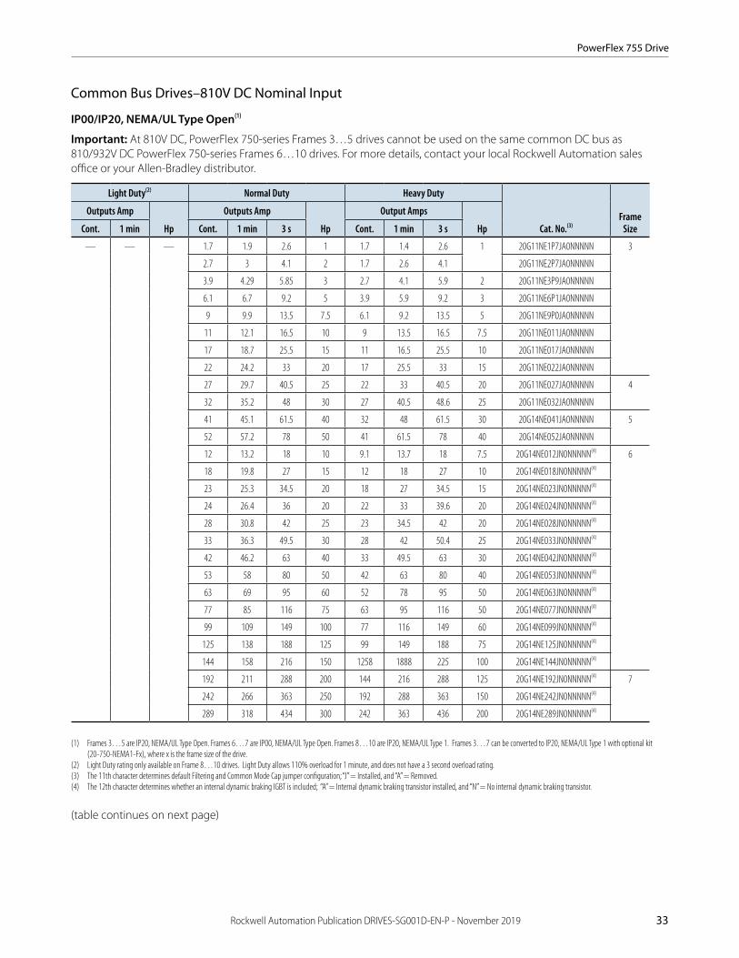
Rockwell Automation Publication DRIVES-SG001D-EN-P - November 2019 33
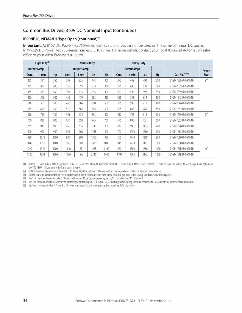
Common Bus Drives–810V DC Nominal Input
IP00/IP20, NEMA/UL Type Open(1)
Important: At 810V DC, PowerFlex 750-series Frames 3…5 drives cannot be used on the same common DC bus as 810/932V DC PowerFlex 750-series Frames 6…10 drives. For more details, contact your local Rockwell Automation sales office or your Allen-Bradley distributor.
Light Duty(2) Normal Duty Heavy Duty
Cat. No.(3)Frame
Size
Outputs Amp
Hp
Outputs Amp
Hp
Output Amps
HpCont. 1 min Cont. 1 min 3 s Cont. 1 min 3 s
— — — 1.7 1.9 2.6 1 1.7 1.4 2.6 1 20G11NE1P7JA0NNNNN 3
2.7 3 4.1 2 1.7 2.6 4.1 20G11NE2P7JA0NNNNN
3.9 4.29 5.85 3 2.7 4.1 5.9 2 20G11NE3P9JA0NNNNN
6.1 6.7 9.2 5 3.9 5.9 9.2 3 20G11NE6P1JA0NNNNN
9 9.9 13.5 7.5 6.1 9.2 13.5 5 20G11NE9P0JA0NNNNN
11 12.1 16.5 10 9 13.5 16.5 7.5 20G11NE011JA0NNNNN
17 18.7 25.5 15 11 16.5 25.5 10 20G11NE017JA0NNNNN
22 24.2 33 20 17 25.5 33 15 20G11NE022JA0NNNNN
27 29.7 40.5 25 22 33 40.5 20 20G11NE027JA0NNNNN 4
32 35.2 48 30 27 40.5 48.6 25 20G11NE032JA0NNNNN
41 45.1 61.5 40 32 48 61.5 30 20G14NE041JA0NNNNN 5
52 57.2 78 50 41 61.5 78 40 20G14NE052JA0NNNNN
12 13.2 18 10 9.1 13.7 18 7.5 20G14NE012JN0NNNNN(4) 6
18 19.8 27 15 12 18 27 10 20G14NE018JN0NNNNN(4)
23 25.3 34.5 20 18 27 34.5 15 20G14NE023JN0NNNNN(4)
24 26.4 36 20 22 33 39.6 20 20G14NE024JN0NNNNN(4)
28 30.8 42 25 23 34.5 42 20 20G14NE028JN0NNNNN(4)
33 36.3 49.5 30 28 42 50.4 25 20G14NE033JN0NNNNN(4)
42 46.2 63 40 33 49.5 63 30 20G14NE042JN0NNNNN(4)
53 58 80 50 42 63 80 40 20G14NE053JN0NNNNN(4)
63 69 95 60 52 78 95 50 20G14NE063JN0NNNNN(4)
77 85 116 75 63 95 116 50 20G14NE077JN0NNNNN(4)
99 109 149 100 77 116 149 60 20G14NE099JN0NNNNN(4)
125 138 188 125 99 149 188 75 20G14NE125JN0NNNNN(4)
144 158 216 150 1258 1888 225 100 20G14NE144JN0NNNNN(4)
192 211 288 200 144 216 288 125 20G14NE192JN0NNNNN(4) 7
242 266 363 250 192 288 363 150 20G14NE242JN0NNNNN(4)
289 318 434 300 242 363 436 200 20G14NE289JN0NNNNN(4)
(1) Frames 3…5 are IP20, NEMA/UL Type Open. Frames 6…7 are IP00, NEMA/UL Type Open. Frames 8…10 are IP20, NEMA/UL Type 1. Frames 3…7 can be converted to IP20, NEMA/UL Type 1 with optional kit (20-750-NEMA1-Fx), where x is the frame size of the drive.
(2) Light Duty rating only available on Frame 8…10 drives. Light Duty allows 110% overload for 1 minute, and does not have a 3 second overload rating.(3) The 11th character determines default Filtering and Common Mode Cap jumper configuration; “J” = Installed, and “A” = Removed.(4) The 12th character determines whether an internal dynamic braking IGBT is included; “A” = Internal dynamic braking transistor installed, and “N” = No internal dynamic braking transistor.
(table continues on next page)
PowerFlex 755 Drive
34 Rockwell Automation Publication DRIVES-SG001D-EN-P - November 2019
Common Bus Drives–810V DC Nominal Input (continued)
IP00/IP20, NEMA/UL Type Open (continued)(1)
Important: At 810V DC, PowerFlex 750-series Frames 3…5 drives cannot be used on the same common DC bus as 810/932V DC PowerFlex 750-series Frames 6…10 drives. For more details, contact your local Rockwell Automation sales office or your Allen-Bradley distributor.
Light Duty(2) Normal Duty Heavy Duty
Cat. No.(3)(4)(5)Frame
Size
Outputs Amp
Hp
Outputs Amp
Hp
Output Amps
HpCont. 1 min Cont. 1 min 3 s Cont. 1 min 3 s
355 391 350 295 325 443 300 272 408 490 250 21G14*E295JN0NNNNN 8(6)
395 435 400 355 391 533 350 295 443 531 300 21G14*E355JN0NNNNN
435 479 450 395 435 593 400 329 494 592 350 21G14*E395JN0NNNNN
460 506 500 435 479 653 450 355 533 639 350 21G14*E435JN0NNNNN
510 561 500 460 506 690 500 395 593 711 400 21G14*E460JN0NNNNN
545 600 550 510 561 765 500 425 638 765 450 21G14*E510JN0NNNNN
690 759 700 595 655 893 600 510 765 918 500 21G14*E595JN0NNNNN 9(6)
760 836 800 630 693 945 700 595 893 1071 600 21G14*E630JN0NNNNN
835 919 900 760 836 1140 800 630 945 1134 700 21G14*E760JN0NNNNN
900 990 950 825 908 1238 900 700 1050 1260 750 21G14*E825JN0NNNNN
980 1078 1000 900 990 1350 950 760 1140 1368 800 21G14*E900JN0NNNNN
1045 1150 1100 980 1078 1470 1000 815 1223 1467 900 21G14*E980JN0NNNNN
1220 1342 1200 1110 1221 1665 1100 920 1380 1656 1000 21G14*E1K1JN0NNNNN 10(6)
1530 1683 1500 1430 1573 2145 1400 1190 1785 2142 1250 21G14*E1K4JN0NNNNN
(1) Frames 3…5 are IP20, NEMA/UL Type Open. Frames 6…7 are IP00, NEMA/UL Type Open. Frames 8…10 are IP20, NEMA/UL Type 1. Frames 3…7 can be converted to IP20, NEMA/UL Type 1 with optional kit (20-750-NEMA1-Fx), where x is the frame size of the drive.
(2) Light Duty rating only available on Frame 8…10 drives. Light Duty allows 110% overload for 1 minute, and does not have a 3 second overload rating.(3) The 6th character (designated by an * in this table) determines the enclosure type. Refer to the Enclosure Type table in the Catalog Number Explanation on page 24.(4) The 11th character determines default Filtering and Common Mode Cap jumper configuration; “J” = Installed, and “A” = Removed.(5) The 12th character determines whether an internal dynamic braking IGBT is included; “A” = Internal dynamic braking transistor installed, and “N” = No internal dynamic braking transistor.(6) A roll-out cart is required with Frame 8…10 drives to assist with power wiring and cabinet mounting. Refer to page 64.

PowerFlex 755 Drive
Rockwell Automation Publication DRIVES-SG001D-EN-P - November 2019 35
Common Bus Drives–810V DC Nominal Input (continued)
IP54, NEMA/UL Type 12
Important: At 810V DC, PowerFlex 750-series Frames 3…5 drives cannot be used on the same common DC bus as 810/932V DC PowerFlex 750-series Frames 6…10 drives. For more details, contact your local Rockwell Automation sales office or your Allen-Bradley distributor.
Light Duty(1) Normal Duty Heavy Duty
Cat. No.(2)Frame
Size
Output Amps
Hp
Output Amps
Hp
Output Amps
HpCont. 1 min Cont. 1 min 3 s Cont. 1 min 3 s
— — — 1.7 1.9 2.6 1 1.7 1.4 2.6 1 20G11GE1P7JA0NNNNN 3
2.7 3 4.1 2 1.7 2.6 4.1 1 20G11GE2P7JA0NNNNN
3.9 4.29 5.85 3 2.7 4.1 5.9 2 20G11GE3P9JA0NNNNN
6.1 6.7 9.2 5 3.9 5.9 9.2 3 20G11GE6P1JA0NNNNN
9 9.9 13.5 7.5 6.1 9.2 13.5 5 20G11GE9P0JA0NNNNN
11 12.1 16.5 10 9 13.5 16.5 7.5 20G11GE011JA0NNNNN
17 18.7 25.5 15 11 16.5 25.5 10 20G11GE017JA0NNNNN
22 24.2 33 20 17 25.5 33 15 20G11GE022JA0NNNNN
27 29.7 40.5 25 22 33 40.5 20 20G11GE027JA0NNNNN 4
32 35.2 48 30 27 40.5 48.6 25 20G11GE032JA0NNNNN
41 45.1 61.5 40 32.0 48 61.5 30 20G14GE041JA0NNNNN 5
12 13.2 18 10 9.1 13.7 18 7.5 20G14GE012JN0NNNNN(3) 6
18 19.8 27 15 12 18 27 10 20G14GE018JN0NNNNN(3)
23 25.3 34.5 20 18 27 34.5 15 20G14GE023JN0NNNNN(3)
24 26.4 36 20 22 33 39.6 20 20G14GE024JN0NNNNN(3)
28 30.8 42 25 23 34.5 42 20 20G14GE028JN0NNNNN(3)
33 36.3 49.5 30 28 42 50.4 25 20G14GE033JN0NNNNN(3)
42 46.2 63 40 33 49.5 63 30 20G14GE042JN0NNNNN(3)
53 58 80 50 42 63 80 40 20G14GE053JN0NNNNN(3)
63 69 95 60 52 78 95 50 20G14GE063JN0NNNNN(3)
77 85 116 75 63 95 116 50 20G14GE077JN0NNNNN(3)
99 109 149 100 77 116 149 60 20G14GE099JN0NNNNN(3)
125 138 188 125 99 149 188 75 20G14GE125JN0NNNNN(3)
144 158 216 150 1258 1888 225 100 20G14GE144JN0NNNNN(3)
192 211 288 200 144 216 288 125 20G14GE192JN0NNNNN(3) 7
242 266 363 250 192 288 363 150 20G14GE242JN0NNNNN(3)
289 318 434 300 242 363 436 200 20G14GE289JN0NNNNN(3)
(1) Light Duty rating only available on Frame 8…10 drives. Light Duty allows 110% overload for 1 minute, and does not have a 3 second overload rating.(2) The 11th character determines default Filtering and Common Mode Cap jumper configuration; “J” = Installed, and “A” = Removed.(3) The 12th character determines whether an internal dynamic braking IGBT is included; “A” = Internal dynamic braking transistor installed, and “N” = No internal dynamic braking transistor.
(table continues on next page)

PowerFlex 755 Drive
36 Rockwell Automation Publication DRIVES-SG001D-EN-P - November 2019
Common Bus Drives–810V DC Nominal Input (continued)
IP54, NEMA/UL Type 12 (continued)
Important: At 810V DC, PowerFlex 750-series Frames 3…5 drives cannot be used on the same common DC bus as 810/932V DC PowerFlex 750-series Frames 6…10 drives. For more details, contact your local Rockwell Automation sales office or your Allen-Bradley distributor.
Light Duty(1) Normal Duty Heavy Duty
Cat. No.(2)(3)(4)Frame
Size
Output Amps
Hp
Output Amps
Hp
Output Amps
HpCont. 1 min Cont. 1 min 3 s Cont. 1 min 3 s
355 391 350 295 325 443 300 272 408 490 250 21G14*E295JN0NNNNN 8(5)
395 435 400 355 391 533 350 295 443 531 300 21G14*E355JN0NNNNN
435 479 450 395 435 593 400 329 494 592 350 21G14*E395JN0NNNNN
460 506 500 435 479 653 450 355 533 639 350 21G14*E435JN0NNNNN
510 561 500 460 506 690 500 395 593 711 400 21G14*E460JN0NNNNN
545 600 550 510 561 765 500 425 638 765 450 21G14*E510JN0NNNNN
690 759 700 595 655 893 600 510 765 918 500 21G14*E595JN0NNNNN 9(5)
760 836 800 630 693 945 700 595 893 1071 600 21G14*E630JN0NNNNN
835 919 900 760 836 1140 800 630 945 1134 700 21G14*E760JN0NNNNN
900 990 950 825 908 1238 900 700 1050 1260 750 21G14*E825JN0NNNNN
980 1078 1000 900 990 1350 950 760 1140 1368 800 21G14*E900JN0NNNNN
1045 1150 1100 980 1078 1470 1000 815 1223 1467 900 21G14*E980JN0NNNNN
1220 1342 1200 1110 1221 1665 1100 920 1380 1656 1000 21G14*E1K1JN0NNNNN 10(5)
1530 1683 1500 1430 1573 2145 1400 1190 1785 2142 1250 21G14*E1K4JN0NNNNN
(1) Light Duty rating only available on Frame 8…10 drives. Light Duty allows 110% overload for 1 minute, and does not have a 3 second overload rating.(2) The 6th character (designated by an * in this table) determines the enclosure type. Refer to the Enclosure Type table in the Catalog Number Explanation on page 24.(3) The 11th character determines default Filtering and Common Mode Cap jumper configuration; “J” = Installed, and “A” = Removed.(4) The 12th character determines whether an internal dynamic braking IGBT is included; “A” = Internal dynamic braking transistor installed, and “N” = No internal dynamic braking transistor.(5) A roll-out cart is required with Frame 8…10 drives to assist with power wiring and cabinet mounting. Refer to page 64.

PowerFlex 755 Drive
Rockwell Automation Publication DRIVES-SG001D-EN-P - November 2019 37
Common Bus Drives–810V DC Nominal Input (continued)
Flange Mount (Front: IP20, NEMA/UL Type Open; Back/Heatsink: IP66, NEMA/UL Type 4X)
Important: At 810V DC, PowerFlex 750-series Frames 3…5 drives cannot be used on the same common DC bus as 810/932V DC PowerFlex 750-series Frames 6…10 drives. For more details, contact your local Rockwell Automation sales office or your Allen-Bradley distributor.
Important: Frame 6…7 IP00, NEMA Type Open drives can be converted to a flange mount drive (back/heatsink: IP66, NEMA/UL Type 4X) with an optional user installed flange kit (kit 20-750-FLNG4-F6 for Frame 6, and kit 20-750-FLNG4-F7 for Frame 7). See page 33 for 810V DC, Frame 6…7 IP00, NEMA Type Open drives.
Normal Duty Heavy Duty
Cat. No.(1)Frame
Size
Outputs Amp
Hp
Output Amps
HpCont. 1 min 3 s Cont. 1 min 3 s
1.7 1.9 2.6 1 1.7 1.4 2.6 1 20G11FE1P7JA0NNNNN 3
2.7 3 4.1 2 1.7 2.6 4.1 1 20G11FE2P7JA0NNNNN
3.9 4.29 5.85 3 2.7 4.1 5.9 2 20G11FE3P9JA0NNNNN
6.1 6.7 9.2 5 3.9 5.9 9.2 3 20G11FE6P1JA0NNNNN
9 9.9 13.5 7.5 6.1 9.2 13.5 5 20G11FE9P0JA0NNNNN
11 12.1 16.5 10 9 13.5 16.5 7.5 20G11FE011JA0NNNNN
17 18.7 25.5 15 11 16.5 25.5 10 20G11FE017JA0NNNNN
22 24.2 33 20 17 25.5 33 15 20G11FE022JA0NNNNN
27 29.7 40.5 25 22 33 40.5 20 20G11FE027JA0NNNNN 4
32 35.2 48 30 27 40.5 48.6 25 20G11FE032JA0NNNNN
41 45.1 61.5 40 32 48 61.5 30 20G14FE041JA0NNNNN 5
52 57.2 78 50 41 61.5 78.0 40 20G14FE052JA0NNNNN
(1) The 11th character determines default Filtering and Common Mode Cap jumper configuration. “J” = Installed, “A” = Removed.

PowerFlex 755 Drive
38 Rockwell Automation Publication DRIVES-SG001D-EN-P - November 2019
Common Bus Drives–932V DC Nominal Input
IP00/IP20, NEMA/UL Type Open(1)
Light Duty(2) Normal Duty Heavy Duty
Cat. No.(3)Frame
Size
Output Amps
kW
Output Amps
kW
Output Amps
kWCont. 1 min Cont. 1 min 3 s Cont. 1 min 3 s
— — — 12 13.2 18 7.5 9 13.5 18 5.5 20G14NF012JN0NNNNN(4) 6
15 16.5 22.5 11 12 18 22.5 7.5 20G14NF015JN0NNNNN(4)
20 22 30 15 15 22.5 30 11 20G14NF020JN0NNNNN(4)
23 25.3 34.5 18.5 20 30 36 15 20G14NF023JN0NNNNN(4)
30 33 45 22 23 34.5 45 18.5 20G14NF030JN0NNNNN(4)
34 37.4 51 30 30 45 54 22 20G14NF034JN0NNNNN(4)
46 50.6 69 37 34 51 69 30 20G14NF046JN0NNNNN(4)
50 55 75 45 46 69 83 37 20G14NF050JN0NNNNN(4)
61 67 92 55 50 75 92 45 20G14NF061JN0NNNNN(4)
82 90 123 75 61 92 123 55 20G14NF082JN0NNNNN(4)
98 108 147 90 82 123 148 75 20G14NF098JN0NNNNN(4)
119 131 179 110 98 147 179 90 20G14NF119JN0NNNNN(4)
142 156 213 132 119 179 214 110 20G14NF142JN0NNNNN(4)
171 188 257 160 142 213 257 132 20G14NF171JN0NNNNN(4) 7
212 233 318 200 171 257 318 160 20G14NF212JN0NNNNN(4)
263 289 395 250 212 318 395 200 20G14NF263JN0NNNNN(4)
330 363 315 265 292 398 250 215 323 387 200 21G14*F265JN0NNNNN(5) 8(6)
370 407 355 330 363 495 315 265 398 477 250 21G14*F330JN0NNNNN(5)
410 451 400 370 407 555 355 308 462 554 300 21G14*F370JN0NNNNN(5)
460 506 450 415 457 623 400 370 555 666 355 21G14*F415JN0NNNNN(5)
500 550 500 460 506 690 450 375 563 675 375 21G14*F460JN0NNNNN(5)
530 583 530 500 550 750 500 413 620 743 400 21G14*F500JN0NNNNN(5)
650 715 630 590 649 885 560 460 690 828 450 21G14*F590JN0NNNNN(5) 9(6)
710 781 710 650 715 975 630 500 750 900 500 21G14*F650JN0NNNNN(5)
790 869 800 710 781 1065 710 590 885 1062 560 21G14*F710JN0NNNNN(5)
860 946 850 765 842 1148 750 650 975 1170 630 21G14*F765JN0NNNNN(5)
960 1056 900 795 875 1193 800 750 1125 1350 710 21G14*F795JN0NNNNN(5)
1020 1122 1000 960 1056 1440 900 795 1193 1431 800 21G14*F960JN0NNNNN(5)
1150 1265 1100 1040 1144 1560 1000 865 1298 1557 900 21G14*F1K0JN0NNNNN(5) 10(6)
1485 1634 1500 1400 1540 2100 1400 1160 1740 2088 1120 21G14*F1K4JN0NNNNN(5)
(1) Frames 6…7 are IP00, NEMA/UL Type Open. Frames 8…10 are IP20, NEMA/UL Type 1. Frames 6…7 can be converted to IP20, NEMA/UL Type 1 with optional kit (20-750-NEMA1-Fx), where x is the frame size of the drive.
(2) Light Duty rating only available on Frame 8…10 drives. Light Duty allows 110% overload for 1 minute, and does not have a 3 second overload rating.(3) The 11th character determines default Filtering and Common Mode Cap jumper configuration; “J” = Installed, and “A” = Removed.(4) The 12th character determines whether an internal dynamic braking IGBT is included; “A” = Internal dynamic braking transistor installed, and “N” = No internal dynamic braking transistor.(5) The 6th character (designated by an * in this table) determines the enclosure type. Refer to the Enclosure Type table in the Catalog Number Explanation on page 24.(6) A roll-out cart is required with Frame 8…10 drives to assist with power wiring and cabinet mounting. Refer to page 64.

PowerFlex 755 Drive
Rockwell Automation Publication DRIVES-SG001D-EN-P - November 2019 39
Common Bus Drives–932V DC Nominal Input (continued)
IP54, NEMA/UL Type 12
Light Duty(1) Normal Duty Heavy Duty
Cat. No.(2)Frame
Size
Output Amps
kW
Output Amps
kW
Output Amps
kWCont. 1 min Cont. 1 min 3 s Cont. 1 min 3 s
— — — 12 13.2 18 7.5 9 13.5 18 5.5 20G14GF012JN0NNNNN(3) 6
15 16.5 22.5 11 12 18 22.5 7.5 20G14GF015JN0NNNNN(3)
20 22 30 15 15 22.5 30 11 20G14GF020JN0NNNNN(3)
23 25.3 34.5 18.5 20 30 36 15 20G14GF023JN0NNNNN(3)
30 33 45 22 23 34.5 45 18.5 20G14GF030JN0NNNNN(3)
34 37.4 51 30 30 45 54 22 20G14GF034JN0NNNNN(3)
46 50.6 69 37 34 51 69 30 20G14GF046JN0NNNNN(3)
50 55 75 45 46 69 83 37 20G14GF050JN0NNNNN(3)
61 67 92 55 50 75 92 45 20G14GF061JN0NNNNN(3)
82 90 123 75 61 92 123 55 20G14GF082JN0NNNNN(3)
98 108 147 90 82 123 148 75 20G14GF098JN0NNNNN(3)
119 131 179 110 98 147 179 90 20G14GF119JN0NNNNN(3)
142 156 213 132 119 179 214 110 20G14GF142JN0NNNNN(3)
171 188 257 160 142 213 257 132 20G14GF171JN0NNNNN(3) 7
212 233 318 200 171 257 318 160 20G14GF212JN0NNNNN(3)
263 289 395 250 212 318 395 200 20G14GF263JN0NNNNN(3)
330 363 315 265 292 398 250 215 323 387 200 21G14*F265JN0NNNNN(4) 8(5)
370 407 355 330 363 495 315 265 398 477 250 21G14*F330JN0NNNNN(4)
410 451 400 370 407 555 355 308 462 554 300 21G14*F370JN0NNNNN(4)
460 506 450 415 457 623 400 370 555 666 355 21G14*F415JN0NNNNN(4)
500 550 500 460 506 690 450 375 563 675 375 21G14*F460JN0NNNNN(4)
530 583 530 500 550 750 500 413 620 743 400 21G14*F500JN0NNNNN(4)
650 715 630 590 649 885 560 460 690 828 450 21G14*F590JN0NNNNN(4) 9(5)
710 781 710 650 715 975 630 500 750 900 500 21G14*F650JN0NNNNN(4)
790 869 800 710 781 1065 710 590 885 1062 560 21G14*F710JN0NNNNN(4)
860 946 850 765 842 1148 750 650 975 1170 630 21G14*F765JN0NNNNN(4)
960 1056 900 795 875 1193 800 750 1125 1350 710 21G14*F795JN0NNNNN(4)
1020 1122 1000 960 1056 1440 900 795 1193 1431 800 21G14*F960JN0NNNNN(4)
1150 1265 1100 1040 1144 1560 1000 865 1298 1557 900 21G14*F1K0JN0NNNNN(4) 10(5)
1485 1634 1500 1400 1540 2100 1400 1160 1740 2088 1120 21G14*F1K4JN0NNNNN(4)
(1) Light Duty rating only available on Frame 8…10 drives. Light Duty allows 110% overload for 1 minute, and does not have a 3 second overload rating.(2) The 11th character determines default Filtering and Common Mode Cap jumper configuration; “J” = Installed, and “A” = Removed.(3) The 12th character determines whether an internal dynamic braking IGBT is included; “A” = Internal dynamic braking transistor installed, and “N” = No internal dynamic braking transistor.(4) The 6th character (designated by an * in this table) determines the enclosure type. Refer to the Enclosure Type table in the Catalog Number Explanation on page 24.(5) A roll-out cart is required with Frame 8…10 drives to assist with power wiring and cabinet mounting. Refer to page 64.
Flange Mount (Front: IP20, NEMA/UL Type Open; Back/Heatsink: IP66, NEMA/UL Type 4X)
Tip: Frame 6…7 IP00, NEMA Type Open drives can be converted to a flange mount drive (Back/Heatsink: IP66, NEMA/UL Type 4X) with an optional user installed flange kit (20-750-FLNG4-F6 for Frame 6, and 20-750-FLNG4-F7 for Frame 7).
See page 38 for 932V DC, Frame 6…7 IP00, NEMA Type Open drives.

PowerFlex 755 Drive
40 Rockwell Automation Publication DRIVES-SG001D-EN-P - November 2019
PowerFlex 755 Floor Mount Drives for Open Frame Designs
Floor mount, open frame drives are for applications that require power ranges from 215 kW to 1500kW (250 Hp…2000 Hp) and are contained within an enclosure of your choosing. These drives use the same drive unit(s) as standard IP20 and IP54 product. Open Frame applications can accommodate Common Bus DC input systems.
Floor mount, open frame drives can also be horizontally mounted, with derating. Refer to publication 750-IN020, the PowerFlex 755 IP00 NEMA/UL Open Type Drive Installation Instructions, for details.
To order an IP00 drive:
1. Using the tables that follow, locate your desired drive output values.
2. Select the Base Drive Catalog Number for your desired output values.
3. Note the Quantity Required.
4. Order the specified quantity (1, 2, or 3) of the Base Drive Catalog Number.
5. Refer to page 64 for option kits and publication 750-IN020 for installation details.
Common Bus Drives–540V DC Nominal Input
Light Duty (-LD) Normal Duty (-ND) Heavy Duty (-HD)
Base Drive Cat. No.(1)Quantity Required
Equivalent Frame Size(2)
Output Amps
kW
Output Amps
kW
Output Amps
kWCont. Cont. Cont.
540 315 460 250 385 200 20G14TC460JN0NNNNN 1 8
585 315 540 315 456 250 20G14TC540JN0NNNNN
612 355 567 315 472 250 20G14TC567JN0NNNNN
750 400 650 355 540 315 20G14TC650JN0NNNNN
796 450 750 400 585 315 20G14TC750JN0NNNNN
832 450 770 400 642 355 20G14TC770JN0NNNNN
1040 560 910 500 750 400 20G14TC460JN0NNNNN 2 9
1090 630 1040 560 880 500 20G14TC540JN0NNNNN
1175 710 1090 630 910 500 20G14TC567JN0NNNNN
1465 800 1175 710 1040 560 20G14TC650JN0NNNNN
1480 850 1465 800 1090 630 20G14TC750JN0NNNNN
1600 900 1480 850 1175 710 20G14TC770JN0NNNNN
1715 1000 1590 900 1325 710 20G14TC567JN0NNNNN 3 10
2330 1400 2150 1250 1800 1000 20G14TC770JN0NNNNN
(1) The 11th character determines default filtering and common mode cap jumper configuration. “J” = Installed, “A” = Removed.(2) A roll-out cart is required with Frame 8…10 drives to assist with power wiring and cabinet mounting. Refer to page 64.
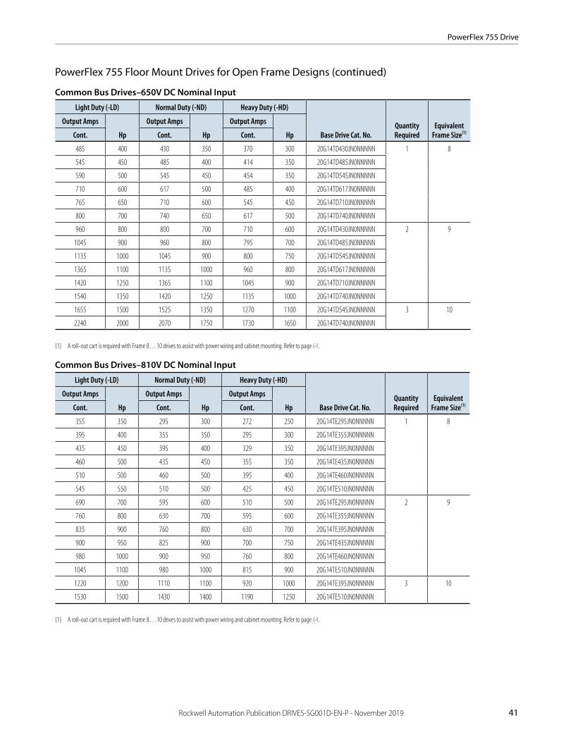
PowerFlex 755 Drive
Rockwell Automation Publication DRIVES-SG001D-EN-P - November 2019 41
PowerFlex 755 Floor Mount Drives for Open Frame Designs (continued)
Common Bus Drives–650V DC Nominal Input
Light Duty (-LD) Normal Duty (-ND) Heavy Duty (-HD)
Base Drive Cat. No.Quantity Required
Equivalent Frame Size(1)
Output Amps
Hp
Output Amps
Hp
Output Amps
HpCont. Cont. Cont.
485 400 430 350 370 300 20G14TD430JN0NNNNN 1 8
545 450 485 400 414 350 20G14TD485JN0NNNNN
590 500 545 450 454 350 20G14TD545JN0NNNNN
710 600 617 500 485 400 20G14TD617JN0NNNNN
765 650 710 600 545 450 20G14TD710JN0NNNNN
800 700 740 650 617 500 20G14TD740JN0NNNNN
960 800 800 700 710 600 20G14TD430JN0NNNNN 2 9
1045 900 960 800 795 700 20G14TD485JN0NNNNN
1135 1000 1045 900 800 750 20G14TD545JN0NNNNN
1365 1100 1135 1000 960 800 20G14TD617JN0NNNNN
1420 1250 1365 1100 1045 900 20G14TD710JN0NNNNN
1540 1350 1420 1250 1135 1000 20G14TD740JN0NNNNN
1655 1500 1525 1350 1270 1100 20G14TD545JN0NNNNN 3 10
2240 2000 2070 1750 1730 1650 20G14TD740JN0NNNNN
(1) A roll-out cart is required with Frame 8…10 drives to assist with power wiring and cabinet mounting. Refer to page 64.
Common Bus Drives–810V DC Nominal Input
Light Duty (-LD) Normal Duty (-ND) Heavy Duty (-HD)
Base Drive Cat. No.Quantity Required
Equivalent Frame Size(1)
Output Amps
Hp
Output Amps
Hp
Output Amps
HpCont. Cont. Cont.
355 350 295 300 272 250 20G14TE295JN0NNNNN 1 8
395 400 355 350 295 300 20G14TE355JN0NNNNN
435 450 395 400 329 350 20G14TE395JN0NNNNN
460 500 435 450 355 350 20G14TE435JN0NNNNN
510 500 460 500 395 400 20G14TE460JN0NNNNN
545 550 510 500 425 450 20G14TE510JN0NNNNN
690 700 595 600 510 500 20G14TE295JN0NNNNN 2 9
760 800 630 700 595 600 20G14TE355JN0NNNNN
835 900 760 800 630 700 20G14TE395JN0NNNNN
900 950 825 900 700 750 20G14TE435JN0NNNNN
980 1000 900 950 760 800 20G14TE460JN0NNNNN
1045 1100 980 1000 815 900 20G14TE510JN0NNNNN
1220 1200 1110 1100 920 1000 20G14TE395JN0NNNNN 3 10
1530 1500 1430 1400 1190 1250 20G14TE510JN0NNNNN
(1) A roll-out cart is required with Frame 8…10 drives to assist with power wiring and cabinet mounting. Refer to page 64.

PowerFlex 755 Drive
42 Rockwell Automation Publication DRIVES-SG001D-EN-P - November 2019
PowerFlex 755 Floor Mount Drives for Open Frame Designs (continued)
Common Bus Drives–932V DC Nominal Input
Light Duty (-LD) Normal Duty (-ND) Heavy Duty (-HD)
Base Drive Cat. No.(2)Quantity Required
Equivalent Frame Size(2)
Output Amps
kW
Output Amps
kW
Output Amps
kWCont. Cont. Cont.
330 315 265 250 215 200 20G14TF265JN0NNNNN 1 8
370 355 330 315 265 250 20G14TF330JN0NNNNN
410 400 370 355 308 300 20G14TF370JN0NNNNN
460 450 415 400 370 355 20G14TF415JN0NNNNN
500 500 460 450 375 375 20G14TF460JN0NNNNN
530 530 500 500 413 400 20G14TF500JN0NNNNN
650 630 590 560 460 450 20G14TF265JN0NNNNN 2 9
710 710 650 630 500 500 20G14TF330JN0NNNNN
790 800 710 710 590 560 20G14TF370JN0NNNNN
860 850 765 750 650 630 20G14TF415JN0NNNNN
960 900 795 800 750 710 20G14TF460JN0NNNNN
1020 1000 960 900 795 800 20G14TF500JN0NNNNN
1150 1100 1040 1000 865 900 20G14TF370JN0NNNNN 3 10
1485 1500 1400 1400 1160 1120 20G14TF500JN0NNNNN
(1) The 11th character determines filtering and common mode cap jumper configuration. “J” = Installed, “A” = Removed.(2) A roll-out cart is required with Frame 8…10 drives to assist with power wiring and cabinet mounting. Refer to page 64.

PowerFlex 755 Drive
Rockwell Automation Publication DRIVES-SG001D-EN-P - November 2019 43
PowerFlex 755 Floor Mount Drives for Open Frame Designs (continued)
Kits listed here provide electrical connection, mounting and ventilation provisions along with the control pod and its corresponding cables for PowerFlex 755 Floor Mount Open Frame designs. Other accessories shown include the rollout cart and EMC cores. Refer to publication 750-IN020 for details.
PowerFlex 755 IP00 Option Kits
Description Required?
Frame 8 Frame 9 Frame 10
Cat. No. Qty. Cat. No. Qty. Cat. No. Qty.
Field Termination, DC Input, Common Bus Precharge(1)(2)
Recommended 20-750-BUS5-F8 1 20-750-BUS5-F9 1 20-750-BUS5-F10 1
Field Termination, Inverter, AC Output 20-750-BUS3-F8 1 20-750-BUS3-F9 1 20-750-BUS3-F10 1
Pod, Bucket Assembly Required 20-750-POD1-F8 1 20-750-POD1-F8 1 20-750-POD1-F8 1
Pod, Cable, 24 Volt Supply(4) 20-750-PH1-F8 (3) 20-750-PH2-F9 1 20-750-PH3-F10 1
Cable, Fiber Optic, 560 mm (22 in.)(4) 20-750-FCBL1-F8 1 — — — —
Cable, Fiber Optic, 2.8 m (110 in.)(4) — — 20-750-FCBL1-F10 2 20-750-FCBL1-F10 3
Transceiver, Fiber Optic SK-R1-FTR1-F8 1 SK-R1-FTR1-F8 2
POD, Remote Mounting Kit Optional 20-750-RPD1-F8 1 20-750-RPD1-F9 1 20-750-RPD1-F10 1
Mounting Kit, Back Panel Recommended 20-750-MNT2-F8 1 20-750-MNT2-F9 1 20-750-MNT2-F10 1
Mounting Kit, Floor 20-750-MNT3-F8 1 20-750-MNT3-F9 1 20-750-MNT3-F10 1
Duct, Top Outlet 20-750-DUCT2-F8 1 20-750-DUCT2-F8 2 20-750-DUCT2-F8 3
Duct, Bottom Inlet 20-750-DUCT4-F8 1 20-750-DUCT4-F8 2 20-750-DUCT4-F8 3
Roll-out Cart 20-750-CART1-F8 1 20-750-CART1-F8 1 20-750-CART1-F8 1
Control Power Circuit Breaker(1) 1489-A2D130 1 1489-A2D130 2 1489-A2D130 3
Control Power Circuit Breaker Lock(1) 1489-AAL0A 1 1489-AAL0A 2 1489-AAL0A 3
EMC Core, Inverter Output Optional 20-750-EMCCM1-F8 1 20-750-EMCCM1-F8 2 20-750-EMCCM1-F8 3
(1) Common DC input drives only.(2) EMC input cores are included with the 20-750-BUS5-Fx kits.(3) 24 volt supply cable is included with each Frame 8 drive unit.(4) 20-750-PH1-Fx and 20-750-FBCL1-Fx kits are used if the control pod is mounted in the drive. If the control pod is to be remote mounted (up to 23 m or 75 ft away), order a 20-750-RPD1-Fx kit instead.

PowerFlex 755 Drive
44 Rockwell Automation Publication DRIVES-SG001D-EN-P - November 2019
Connect to a CENTERLINE Motor Control Center (MCC)
To select the splice kit best suited for your application, determine the following.
Important: A splice kit contains three splice plates.
1. Are you connecting to a CENTERLINE® 2100 or CENTERLINE 2500 MCC?
2. While facing the front of the PowerFlex 755 drive, decide to which drive side that you want to connect.
3. Are you connecting PowerFlex 755 floor mount drives together, or are you connecting a PowerFlex 755 floor mount drive to a CENTERLINE MCC?
If you are connecting PowerFlex 755 floor mount drives together or if you are connecting a PowerFlex 755 floor mount drive to a CENTERLINE 2500 MCC, then use PowerFlex 755 CENTERLINE 2500 Splice Kits. Otherwise, use PowerFlex 755 CENTERLINE 2100 Splice Kits.
PowerFlex 755 CENTERLINE 2100 Splice Kits
A complete installation requires one transition section and one bus bar splicing kit. Splicing kits include all necessary hardware to complete all connections.
Mounting Channel Busbar Position(1) Amp Rating Left-side Kit Cat No. Right-side Kit Cat No. Frame Sizes
N/A Transition section(2) N/A 20-750-XSEC-LH-20G 20-750-XSEC-RH-20G 8…10
For use with MCCs that have 1.5 in. mounting channels
Standard 1200 20-750-XBUS-LHNB-1200 20-750-XBUS-RHNB-1200 8…10
2000 20-750-XBUS-LHNB-2000 20-750-XBUS-RHNB-2000
3000 20-750-XBUS-LHNB-3000 20-750-XBUS-RHNB-3000
Bumped back 1200 20-750-XBUS-LHBB-1200 20-750-XBUS-RHBB-1200
2000 20-750-XBUS-LHBB-2000 20-750-XBUS-RHBB-2000
3000 20-750-XBUS-LHBB-3000 20-750-XBUS-RHBB-3000
For use with MCCs that do not have mounting channels
Standard 1200 20-750-XBUS-LLNB-1200 20-750-XBUS-RLNB-1200
2000 20-750-XBUS-LLNB-2000 20-750-XBUS-RLNB-2000
3000 20-750-XBUS-LLNB-3000 20-750-XBUS-RLNB-3000
Bumped back 1200 20-750-XBUS-LLBB-1200 20-750-XBUS-RLBB-1200
2000 20-750-XBUS-LLBB-2000 20-750-XBUS-RLBB-2000
3000 20-750-XBUS-LLBB-3000 20-750-XBUS-RLBB-3000
(1) All busbar positions are 20 in. deep.(2) Hardware is included to install the optional 1.5 in. mounting channel.
PowerFlex 755 CENTERLINE 2500 Splice Kits
DC splicing kits include all necessary hardware to connect to DC+ and DC– MCC bus bars.
Description Amp Rating Cat No. Frame Sizes
DC splice kit to connect right side of drive to a CENTERLINE 2500 cabinet 1200 20-750-DBUSR1-1200 8…10
DC splice kit to connect right side of drive to a CENTERLINE 2500 cabinet 2000 20-750-DBUSR1-2000
DC splice kit to connect right side of drive to a CENTERLINE 2500 cabinet 3000 20-750-DBUSR1-3200
DC splice kit to connect multiple Frame 8…10 drives or to connect left side of drive to a CENTERLINE 2500 cabinet 1200 20-750-DBUSL1-1200
DC splice kit to connect multiple Frame 8…10 drives or to connect left side of drive to a CENTERLINE 2500 cabinet 2000 20-750-DBUSL1-2000
DC splice kit to connect multiple Frame 8…10 drives or to connect left side of drive to a CENTERLINE 2500 cabinet 3000 20-750-DBUSL1-3200

PowerFlex 755 Drive
Rockwell Automation Publication DRIVES-SG001D-EN-P - November 2019 45
Approximate Dimensions and Weights (Frames 1…7)Dimensions are in mm (in.) - weights are in kg (lb)
IP00/IP20, NEMA/UL Type Open
Frame H W D Weight
1 400.5 (15.77) 110 (4.33) 211 (8.31) 6 (12.75)
2 424.2 (16.7) 134.5 (5.3) 212 (8.35) 7.80 (17.2)
3 454 (17.87) 190 (7.48) 11.8 (26.1)
4 474 (18.66) 222 (8.74) 13.6 (30)
5 550 (21.65) 270 (10.63) 20.4 (45)
6 665.5 (26.2) 308 (12.13) 346.4 (13.64) 38.6 (85)
7 881.5 (34.7) 430 (16.93) 349.6 (13.76) 72.6…108.9 (160…240)
IP54, NEMA/UL Type 12
Frame H W D Weight(1)
2 543.2 (21.39) 215.3 (8.48) 222.2 (8.75) 8 (17)
3 551 (21.69) 268 (10.55) 220.1 (8.67) 12 (26)
4 571 (22.48) 300 (11.81) 14 (30)
5 647 (25.47) 348 (13.7) 20 (45)
6 1298.3 (51.11) 609.4 (24) 464.7 (18.3) 91 (200)
7 1614 (63.54) 162 (357)
(1) Weights are approximate. Refer to 750-TD001, the PowerFlex 750-Series Technical Data, for detailed weight information.
Flange Mount
Frame H W D1 D2 Weight(1)
2 481.8 (18.97) 206.2 (8.12) 148.3 (5.84) 63.7 (2.51) 8 (17.0)
3 515 (20.28) 260 (10.24) 127.4 (5.02) 84.6 (3.33) 12 (26.0)
4 535 (21.06) 292 (11.50) 14 (30.0)
5 611 (24.06) 340 (13.39) 20.(45.0)
6 665.5 (26.20) 308 (12.13) 208.4 (8.20) 138.(5.43) 38 (84.0)
7 875 (34.45) 430.0 (16.93) 96 (212.0)
(1) Weights are approximate. Refer to 750-TD001, the PowerFlex 750-Series Technical Data, for detailed weight information.

PowerFlex 755 Drive
46 Rockwell Automation Publication DRIVES-SG001D-EN-P - November 2019
Approximate Dimensions and Weights (Frames 8…10)Dimensions are in mm (in.), and weights are in kg (lb).
Weights are approximate. Refer to 750-TD001, the PowerFlex 750-Series Technical Data, for detailed weight information.
IP20, NEMA/UL Type 1, MCC Style Cabinet
Frame H W D Weight
8 2453 (96.6) 600 (23.6) 600 (23.6) or
800 (31.5)
623 (1374)
9 1200 (47.2) 1246 (2748)
10 1800 (70.9) 1869 (4122)
IP54, NEMA Type 12, MCC Style Cabinet
Frame H W D Weight
8 2477 (97.5) 600 (23.6) 800 (31.5) 898 (35.4) with filter
644 (1419)
9 1200 (47.2) 1287 (2838)
10 1800 (70.9) 1931 (4257)
IP00, NEMA/UL Type Open(1)
Frame H W D
8 2145 (84.45) 778 (30.63) 425 (16.73)
9 1578 (62.12)
10 2378 (93.62)
(1) Refer to 750-TD001, the PowerFlex 750-Series Technical Data, for detailed information.
Maximum Component Weights, Frames 8…10
Component Common DC Input
Converter/DC input with precharge 64 (140)
Inverter 165 (363)
Drive assembly (Open, IP00) 229 (504)

Rockwell Automation Publication DRIVES-SG001D-EN-P - November 2019 47
PowerFlex 755TM Drive System75…4550 kW/100…6000 Hp in voltages from 400…690V AC
Powerful performance. Flexible control.
The PowerFlex 755TM drive system enables coordination of multiple motors based on two main building blocks: regenerative common bus supplies and common bus inverters. The common DC bus optimizes the sizing of the bus supply so that energy consumption remains strictly matched with the requirement of the application.
By packaging inverters and bus supplies in different arrangements and ratings, you can optimize a high power density system with a small footprint. You can also eliminate external multi-phase transformers or filters, and their associated wiring, labor, installation, and maintenance costs.
PowerFlex 755TM at a GlanceInput Ratings 400V AC480V AC600V AC690V AC
75…3640 kW 100…6000 Hp 75…5100 Hp75…4550 kW
Motor Control • Field Oriented Control• Sensorless Vector Control• Flux Vector Control
• V/Hz Control• Economizer• Interior Permanent Magnet
and Surface Permanent Magnet Flux Vector Control
• Voltage Boost
Enclosures • IP21, UL Type 1 • IP54, UL Type 12
Safety Options • Hardwired Safe Torque Off SIL3, PLe, CAT 3
• Hardwired Safe Speed Monitor SIL3, PLe, CAT 4
• Networked Safe Torque Off SIL3, PLe, CAT 3
• Networked Integrated Safety Functions SIL3, PLe, CAT 4
Additional Features
• Active front end ride-through control reduces downtime
• TotalFORCE Technology • Provides harmonic mitigation
and power factor correction• Optional built-in Dv/Dt
filter designed to mitigate reflective wave phenomenon
• Modular construction for easy install and maintenance
• Built-in dual port EtherNet/IP• Predictive diagnostics help
monitor drive components
• Embedded DeviceLogix control
• Adaptive tuning• Bus Observer• Load Observer• LCL Filter Resonance and
failure detection• Auto Restart• Start at PowerUp• Emergency Override• Energy Pause• TorqProve• Line voltage and current
imbalance detection
Options See page 57
1
2
5
3 4
6
4
6
6
5
8
7 7
Regenerative Bus Supply Common Bus Inverters
AC Precharge
LCL Filter
Line Side Converter
Motor Side Inverter
IP21/54 Enclosures
Control Pod
DC Precharge (optional)
Roll-in/rollout design
1 5
2 6
3 7
4 8

PowerFlex 755TM Drive System
48 Rockwell Automation Publication DRIVES-SG001D-EN-P - November 2019
Additional InformationPowerFlex 755T Drive Solutions Brochure, publication 755T-BR001 PowerFlex 750-Series Products with TotalFORCE Control Technical Data, publication 750-TD100
Catalog Number Explanation
20 x D 540 x N N N N N -Cx -Px
C Voltage Rating D Control andPower Options;
x
B
x
A
1
CoolingType
N
DynamicBraking
x
E Various Options
Drive Type
A
Code
G
J
Description
755TM common bus inverters
755TM bus supplies
Input Type
B
Code(1)
D
E
Description
Common bus with DC precharge
Common bus without DC precharge
F
(1) Codes D and E are only available with 20G-type drives. Code F is only available with 20J-type drives.
Regenerative and low harmonic AFE, 755TM Bus Supplies
(1) HIM option depends on catalog configuration; for full details, see footnote 2 on
Door Mounted HIM(1)
E
Code
A
D
Operator Interface and Control
No door mounted HIM with TotalFORCE control
Enhanced LCD, full numeric, IP66, NEMAType 4X/12 with TotalFORCE control
6 Regenerative and low harmonic AFE, 755TM Bus Supplies
Frame Size
6…7
8…15
8…15
8…15
Enclosure
C
Code
3
4
Description
IP21, UL Type 1; floor mount
IP54, UL Type 12; floor mount
N IP00, UL Open Type
(1) Refer to publication 750-TD100 for the full list of EMC C2, EMC C3, and Reflected Wave filtering options available.
Filtering and CM Cap Configuration (1)
D
Code(2)
JK
L
M
EMCFiltering
CM Cap DefaultConfiguration
ReflectedWave Filtering
YesYes
No
No
NoYes
No
Yes
Jumper InstalledJumper Installed
Jumper Installed
Jumper Installed
Frame Size
P Yes NoJumper Installed
8…158…15
7
6…15
8…15
(2) Codes J and K are not configurable with 20G-type drives (input types D or E). Codes K and M are not configurable with 20J-type drives (input type F).
PowerFlex 755TM Common Bus System Example
Item
1
2
Description
PowerFlex 755TM regenerative bus supply
PowerFlex 755TM common bus inverter
3
4
Control bay to support the control pods that control the motors for each inverter
Lower power PowerFlex drives to supportsmaller rated motors
Item
5
6
Description
Kinetix servo drives
Control pod to control the system
7
8
AC precharge module
Line side converter
Item
9
10
Description
LCL filter
Motor side inverter
11 DC precharge module (optional)
2 23 4 5
9 98 8 86 6
6
7 10
11 11
1
10
see page 57
page 57.

PowerFlex 755TM Drive System
Rockwell Automation Publication DRIVES-SG001D-EN-P - November 2019 49
Product Selection
Regenerative Common Bus Supply–400V AC Input
Wall Mounted (Frame 6) Bus Supplies: IP00, UL Open Type Cabinet (Frames 7…15) Bus Supplies: IP21/IP54, UL Types 1/12
Light Duty Normal Duty Heavy Duty
Base Cat. No. Frame SizekW Amps DC kW Amps DC kW Amps DC
106 182 87 150 65 112 20J1xxC140xNxNNNNN 6
128 220 106 182 87 150 20J1xxC176xNxNNNNN
162 279 128 220 106 182 20J1xxC205xNxNNNNN
188 324 162 279 128 220 20J1xxC260xNxNNNNN
228 394 188 324 162 279 20J1xxC302xNxNNNNN-Px 7
286 494 228 294 188 324 20J1xxC367xNxNNNNN-Px
336 579 286 494 228 294 20J1xxC460xNxNNNNN-Px
364 628 336 579 286 494 20J1xxC540xNxNNNNN-Px
384 662 373 644 311 527 20J1xxC585xNxNNNNN-Px
228 394 188 324 162 279 20J1xxC302xNxNNNNN-Cx-Px 8
286 494 228 394 188 324 20J1xxC367xNxNNNNN-Cx-Px
336 579 286 494 228 394 20J1xxC460xNxNNNNN-Cx-Px
364 628 336 579 286 494 20J1xxC540xNxNNNNN-Cx-Px
387 667 364 628 286 494 20J1xxC585xNxNNNNN-Cx-Px
467 805 405 698 336 579 20J1xxC650xNxNNNNN-Cx-Px
479 826 467 805 364 628 20J1xxC750xNxNNNNN-Cx-Px
518 893 479 826 405 698 20J1xxC770xNxNNNNN-Cx-Px
647 1116 572 987 479 826 20J1xxC920xNxNNNNN-Cx-Px 9
678 1170 647 1116 572 987 20J1xxC1K0xNxNNNNN-Cx-Px
735 1268 692 1193 647 1116 20J1xxC1K1xNxNNNNN-Cx-Px
911 1572 731 1261 678 1170 20J1xxC1K2xNxNNNNN-Cx-Px
983 1696 910 1570 731 1261 20J1xxC1K4xNxNNNNN-Cx-Px
1067 1840 984 1697 911 1572 20J1xxC1K6xNxNNNNN-Cx-Px 10
1337 2307 1067 1840 921 1588 20J1xxC1K7xNxNNNNN-Cx-Px
1449 2500 1342 2314 1067 1840 20J1xxC2K1xNxNNNNN-Cx-Px
1915 3303 1772 3057 1449 2500 20J1xxC2K8xNxNNNNN-Cx-Px 11
2393 4127 2204 3801 1886 3254 20J1xxC3K5xNxNNNNN-Cx-Px 12
2847 4912 2634 4546 2226 3839 20J1xxC4K2xNxNNNNN-Cx-Px 13
3779 6519 3496 6030 2954 5095 20J1xxC5K6xNxNNNNN-Cx-Px 14
4711 8126 4358 7517 3684 6352 20J1xxC7K0xNxNNNNN-Cx-Px 15

PowerFlex 755TM Drive System
50 Rockwell Automation Publication DRIVES-SG001D-EN-P - November 2019
Regenerative Common Bus Supply–480V AC Input
Wall Mounted (Frame 6) Bus Supplies: IP00, UL Open Type Cabinet (Frames 7…15) Bus Supplies: IP21/IP54, UL Types 1/12
Light Duty Normal Duty Heavy Duty
Base Cat. No. Frame SizekW Amps DC kW Amps DC kW Amps DC
111 160 90 129 69 99 20J1xxD125xNxNNNNN 6
133 191 111 160 90 129 20J1xxD156xNxNNNNN
177 255 133 191 111 160 20J1xxD186xNxNNNNN
216 311 177 255 133 191 20J1xxD248xNxNNNNN
258 371 216 311 177 255 20J1xxD302xNxNNNNN-Px 7
307 442 258 371 216 311 20J1xxD361xNxNNNNN-Px
347 499 307 442 258 371 20J1xxD430xNxNNNNN-Px
390 560 361 519 307 442 20J1xxD505xNxNNNNN-Px
441 634 429 617 358 514 20J1xxD617xNxNNNNN-Px
258 371 216 311 177 255 20J1xxD302xNxNNNNN-Cx-Px 8
307 442 258 371 216 311 20J1xxD361xNxNNNNN-Cx-Px
347 499 307 442 258 371 20J1xxD430xNxNNNNN-Cx-Px
390 560 361 519 307 442 20J1xxD505xNxNNNNN-Cx-Px
422 607 390 560 307 442 20J1xxD545xNxNNNNN-Cx-Px
508 730 442 635 347 499 20J1xxD617xNxNNNNN-Cx-Px
529 761 508 730 390 560 20J1xxD710xNxNNNNN-Cx-Px
573 823 529 761 442 635 20J1xxD740xNxNNNNN-Cx-Px
687 987 573 823 529 761 20J1xxD800xNxNNNNN-Cx-Px 9
748 1075 687 987 573 823 20J1xxD960xNxNNNNN-Cx-Px
802 1153 748 1075 687 987 20J1xxD1K0xNxNNNNN-Cx-Px
977 1404 812 1167 748 1075 20J1xxD1K1xNxNNNNN-Cx-Px
1087 1563 977 1404 812 1167 20J1xxD1K3xNxNNNNN-Cx-Px
1184 1702 1016 1460 977 1404 20J1xxD1K4xNxNNNNN-Cx-Px 10
1481 2129 1184 1702 1016 1460 20J1xxD1K6xNxNNNNN-Cx-Px
1603 2304 1483 2131 1184 1702 20J1xxD2K0xNxNNNNN-Cx-Px
2118 3044 1959 2816 1603 2304 20J1xxD2K6xNxNNNNN-Cx-Px 11
2632 3784 2436 3501 2132 3065 20J1xxD3K4xNxNNNNN-Cx-Px 12
3149 4527 2912 4186 2430 3493 20J1xxD4K0xNxNNNNN-Cx-Px 13
4180 6008 3865 5555 3225 4636 20J1xxD5K4xNxNNNNN-Cx-Px 14
5210 7489 4818 6925 4020 5779 20J1xxD6K7xNxNNNNN-Cx-Px 15

PowerFlex 755TM Drive System
Rockwell Automation Publication DRIVES-SG001D-EN-P - November 2019 51
Regenerative Common Bus Supply–600V AC Input
Wall Mounted (Frame 6) Bus Supplies: IP00, UL Open Type Cabinet (Frames 7…15) Bus Supplies: IP21/IP54, UL Types 1/12
Light Duty Normal Duty Heavy Duty
Base Cat. No. Frame SizekW Amps DC kW Amps DC kW Amps DC
89 102 69 79 56 64 20J1xxE077xNxNNNNN 6
112 129 89 102 69 79 20J1xxE099xNxNNNNN
129 148 112 129 89 102 20J1xxE125xNxNNNNN
171 197 129 148 112 129 20J1xxE144xNxNNNNN
217 249 171 197 129 148 20J1xxE192xNxNNNNN-Px 7
263 303 217 249 171 197 20J1xxE242xNxNNNNN-Px
317 365 263 303 217 249 20J1xxE295xNxNNNNN-Px
353 406 317 365 263 303 20J1xxE355xNxNNNNN-Px
389 447 353 406 317 365 20J1xxE395xNxNNNNN-Px
263 303 217 249 171 197 20J1xxE242xNxNNNNN-Cx-Px 8
317 365 263 303 217 249 20J1xxE295xNxNNNNN-Cx-Px
353 406 317 365 263 303 20J1xxE355xNxNNNNN-Cx-Px
389 447 353 406 317 365 20J1xxE395xNxNNNNN-Cx-Px
456 524 389 447 353 406 20J1xxE435xNxNNNNN-Cx-Px
518 596 487 560 403 463 20J1xxE545xNxNNNNN-Cx-Px
617 710 518 596 487 560 20J1xxE595xNxNNNNN-Cx-Px 9
680 782 617 710 532 612 20J1xxE690xNxNNNNN-Cx-Px
737 848 680 782 617 710 20J1xxE760xNxNNNNN-Cx-Px
877 1008 737 848 680 782 20J1xxE825xNxNNNNN-Cx-Px
985 1133 877 1008 737 848 20J1xxE980xNxNNNNN-Cx-Px
1091 1255 935 1075 877 1008 20J1xxE1K1xNxNNNNN-Cx-Px 10
1279 1471 1091 1255 935 1075 20J1xxE1K2xNxNNNNN-Cx-Px
1452 1670 1279 1471 1091 1255 20J1xxE1K5xNxNNNNN-Cx-Px
1919 2207 1740 2001 1520 1748 20J1xxE2K0xNxNNNNN-Cx-Px 11
2386 2744 2164 2489 1851 2129 20J1xxE2K4xNxNNNNN-Cx-Px 12
2851 3278 2678 3080 2215 2547 20J1xxE2K9xNxNNNNN-Cx-Px 13
3784 4351 3555 4088 2939 3380 20J1xxE3K9xNxNNNNN-Cx-Px 14
4717 5424 4432 5096 3664 4213 20J1xxE4K9xNxNNNNN-Cx-Px 15

PowerFlex 755TM Drive System
52 Rockwell Automation Publication DRIVES-SG001D-EN-P - November 2019
Regenerative Common Bus Supply–690V AC Input
Wall Mounted (Frame 6) Bus Supplies: IP00, UL Open Type Cabinet (Frames 7…15) Bus Supplies: IP21/IP54, UL Types 1/12
Light Duty Normal Duty Heavy Duty
Base Cat. No. Frame SizekW Amps DC kW Amps DC kW Amps DC
101 101 84 84 63 63 20J1xxF082xNxNNNNN 6
122 122 101 101 84 84 20J1xxF098xNxNNNNN
146 146 122 122 101 101 20J1xxF119xNxNNNNN
176 176 146 146 122 122 20J1xxF142xNxNNNNN
221 221 176 176 146 146 20J1xxF171xNxNNNNN-Px 7
272 272 221 221 176 176 20J1xxF215xNxNNNNN-Px
339 339 272 272 221 221 20J1xxF265xNxNNNNN-Px
380 380 339 339 272 272 20J1xxF330xNxNNNNN-Px
426 426 380 380 339 339 20J1xxF370xNxNNNNN-Px
272 272 221 221 176 176 20J1xxF215xNxNNNNN-Cx-Px 8
339 339 272 272 221 221 20J1xxF265xNxNNNNN-Cx-Px
380 380 339 339 272 272 20J1xxF330xNxNNNNN-Cx-Px
426 426 380 380 339 339 20J1xxF370xNxNNNNN-Cx-Px
472 472 426 426 380 380 20J1xxF415xNxNNNNN-Cx-Px
580 580 518 518 426 426 20J1xxF505xNxNNNNN-Cx-Px
580 580 580 580 518 518 20J1xxF565xNxNNNNN-Cx-Px 9
754 754 667 667 580 580 20J1xxF650xNxNNNNN-Cx-Px
842 842 754 754 667 667 20J1xxF735xNxNNNNN-Cx-Px
944 944 842 842 754 754 20J1xxF820xNxNNNNN-Cx-Px
1102 1102 944 944 842 842 20J1xxF920xNxNNNNN-Cx-Px
1180 1180 1057 1057 944 944 20J1xxF1K0xNxNNNNN-Cx-Px 10
1380 1380 1180 1180 1057 1057 20J1xxF1K1xNxNNNNN-Cx-Px
1624 1624 1456 1456 1193 1193 20J1xxF1K4xNxNNNNN-Cx-Px
2146 2146 1914 1914 1576 1576 20J1xxF1K8xNxNNNNN-Cx-Px 11
2668 2668 2379 2379 2073 2073 20J1xxF2K3xNxNNNNN-Cx-Px 12
3190 3190 2849 2849 2343 2343 20J1xxF2K7xNxNNNNN-Cx-Px 13
4234 4234 3781 3781 3110 3110 20J1xxF3K6xNxNNNNN-Cx-Px 14
5278 5278 4714 4714 3877 3877 20J1xxF4K5xNxNNNNN-Cx-Px 15

PowerFlex 755TM Drive System
Rockwell Automation Publication DRIVES-SG001D-EN-P - November 2019 53
Common Bus Inverters–540V DC Nominal
IP21/IP54, UL Types 1/12
Light Duty Normal Duty Heavy Duty
Base Cat. No. Frame SizekW Amps AC kW Amps AC kW Amps AC
200 367 160 302 132 260 20G1xxC302xNxNNNNN-Cx-Px 8
250 460 200 367 160 302 20G1xxC367xNxNNNNN-Cx-Px
315 540 250 460 200 367 20G1xxC460xNxNNNNN-Cx-Px
315 585 315 540 250 460 20G1xxC540xNxNNNNN-Cx-Px
355 650 315 585 250 472 20G1xxC585xNxNNNNN-Cx-Px
400 750 355 650 315 540 20G1xxC650xNxNNNNN-Cx-Px
450 796 400 750 315 585 20G1xxC750xNxNNNNN-Cx-Px
450 832 400 770 355 650 20G1xxC770xNxNNNNN-Cx-Px
560 1040 500 920 400 770 20G1xxC920xNxNNNNN-Cx-Px 9
630 1090 560 1040 500 920 20G1xxC1K0xNxNNNNN-Cx-Px
710 1182 630 1112 500 1040 20G1xxC1K1xNxNNNNN-Cx-Px
800 1465 710 1175 560 1090 20G1xxC1K2xNxNNNNN-Cx-Px
850 1581 800 1465 630 1175 20G1xxC1K4xNxNNNNN-Cx-Px
1000 1715 850 1590 710 1465 20G1xxC1K6xNxNNNNN-Cx-Px 10
1250 2150 1000 1715 800 1480 20G1xxC1K7xNxNNNNN-Cx-Px
1400 2330 1250 2156 1000 1715 20G1xxC2K1xNxNNNNN-Cx-Px
1800 3078 1650 2849 1400 2330 20G1xxC2K8xNxNNNNN-Cx-Px 11
2200 3846 2000 3542 1650 3032 20G1xxC3K5xNxNNNNN-Cx-Px 12
2475 4576 2200 4235 1953 3575 20G1xxC4K2xNxNNNNN-Cx-Px 13
3285 6074 2920 5621 2592 4745 20G1xxC5K6xNxNNNNN-Cx-Px 14
4095 7571 3640 7007 3231 5915 20G1xxC7K0xNxNNNNN-Cx-Px 15

PowerFlex 755TM Drive System
54 Rockwell Automation Publication DRIVES-SG001D-EN-P - November 2019
Common Bus Inverters–650V DC Nominal
IP21/IP54, UL Types 1/12
Light Duty Normal Duty Heavy Duty
Base Cat. No. Frame SizeHp Amps AC Hp Amps AC Hp Amps AC
300 361 250 302 200 248 20G1xxD302xNxNNNNN-Cx-Px 8
350 430 300 361 250 302 20G1xxD361xNxNNNNN-Cx-Px
400 485 350 430 300 361 20G1xxD430xNxNNNNN-Cx-Px
450 545 400 505 350 430 20G1xxD505xNxNNNNN-Cx-Px
500 617 450 545 350 454 20G1xxD545xNxNNNNN-Cx-Px
600 710 500 617 400 485 20G1xxD617xNxNNNNN-Cx-Px
650 765 600 710 450 545 20G1xxD710xNxNNNNN-Cx-Px
700 800 650 740 500 617 20G1xxD740xNxNNNNN-Cx-Px
800 960 700 800 600 740 20G1xxD800xNxNNNNN-Cx-Px 9
900 1045 800 960 700 800 20G1xxD960xNxNNNNN-Cx-Px
1000 1135 900 1045 750 960 20G1xxD1K0xNxNNNNN-Cx-Px
1100 1365 1000 1135 800 1045 20G1xxD1K1xNxNNNNN-Cx-Px
1250 1520 1100 1365 900 1135 20G1xxD1K3xNxNNNNN-Cx-Px
1500 1655 1250 1420 1000 1365 20G1xxD1K4xNxNNNNN-Cx-Px 10
1800 2070 1500 1655 1100 1420 20G1xxD1K6xNxNNNNN-Cx-Px
2000 2240 1800 2072 1500 1655 20G1xxD2K0xNxNNNNN-Cx-Px
2600 2960 2400 2738 2000 2240 20G1xxD2K6xNxNNNNN-Cx-Px 11
3300 3696 3000 3404 2400 2980 20G1xxD3K4xNxNNNNN-Cx-Px 12
3900 4400 3600 4070 2800 3394 20G1xxD4K0xNxNNNNN-Cx-Px 13
5200 5840 4800 5402 3700 4504 20G1xxD5K4xNxNNNNN-Cx-Px 14
6400 7280 6000 6734 4600 5615 20G1xxD6K7xNxNNNNN-Cx-Px 15
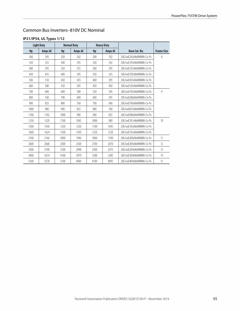
PowerFlex 755TM Drive System
Rockwell Automation Publication DRIVES-SG001D-EN-P - November 2019 55
Common Bus Inverters–810V DC Nominal
IP21/IP54, UL Types 1/12
Light Duty Normal Duty Heavy Duty
Base Cat. No. Frame SizeHp Amps AC Hp Amps AC Hp Amps AC
300 295 250 242 200 192 20G1xxE242xNxNNNNN-Cx-Px 8
350 355 300 295 250 242 20G1xxE295xNxNNNNN-Cx-Px
400 395 350 355 300 295 20G1xxE355xNxNNNNN-Cx-Px
450 435 400 395 350 355 20G1xxE395xNxNNNNN-Cx-Px
500 510 450 435 400 395 20G1xxE435xNxNNNNN-Cx-Px
600 580 550 545 450 450 20G1xxE545xNxNNNNN-Cx-Px
700 690 600 580 550 545 20G1xxE595xNxNNNNN-Cx-Px 9
800 760 700 690 600 595 20G1xxE690xNxNNNNN-Cx-Px
900 825 800 760 700 690 20G1xxE760xNxNNNNN-Cx-Px
1000 980 900 825 800 760 20G1xxE825xNxNNNNN-Cx-Px
1100 1102 1000 980 900 825 20G1xxE980xNxNNNNN-Cx-Px
1250 1220 1100 1045 1000 980 20G1xxE1K1xNxNNNNN-Cx-Px 10
1500 1430 1250 1220 1100 1045 20G1xxE1K2xNxNNNNN-Cx-Px
1600 1624 1500 1430 1250 1220 20G1xxE1K5xNxNNNNN-Cx-Px
2100 2146 2000 1946 1800 1700 20G1xxE2K0xNxNNNNN-Cx-Px 11
2600 2668 2500 2420 2100 2070 20G1xxE2K4xNxNNNNN-Cx-Px 12
3300 3190 3100 2998 2500 2475 20G1xxE2K9xNxNNNNN-Cx-Px 13
4400 4234 4100 3979 3300 3285 20G1xxE3K9xNxNNNNN-Cx-Px 14
5500 5278 5100 4960 4100 4095 20G1xxE4K9xNxNNNNN-Cx-Px 15

PowerFlex 755TM Drive System
56 Rockwell Automation Publication DRIVES-SG001D-EN-P - November 2019
Common Bus Inverters–932V DC Nominal
IP21/IP54, UL Types 1/12
Light Duty Normal Duty Heavy Duty
Base Cat. No. Frame SizekW Amps AC kW Amps AC kW Amps AC
250 265 200 215 160 171 20G1xxF215xNxNNNNN-Cx-Px 8
315 330 250 265 200 215 20G1xxF265xNxNNNNN-Cx-Px
355 370 315 330 250 265 20G1xxF330xNxNNNNN-Cx-Px
400 415 355 370 315 330 20G1xxF370xNxNNNNN-Cx-Px
450 460 400 415 355 370 20G1xxF415xNxNNNNN-Cx-Px
560 565 500 505 400 415 20G1xxF505xNxNNNNN-Cx-Px
630 650 560 565 500 505 20G1xxF565xNxNNNNN-Cx-Px 9
710 735 630 650 560 565 20G1xxF650xNxNNNNN-Cx-Px
800 820 710 735 630 650 20G1xxF735xNxNNNNN-Cx-Px
900 920 800 820 710 735 20G1xxF820xNxNNNNN-Cx-Px
1000 1074 900 920 800 820 20G1xxF920xNxNNNNN-Cx-Px
1100 1150 1000 1030 900 920 20G1xxF1K0xNxNNNNN-Cx-Px 10
1250 1344 1100 1150 1000 1030 20G1xxF1K1xNxNNNNN-Cx-Px
1500 1582 1400 1419 1100 1162 20G1xxF1K4xNxNNNNN-Cx-Px
2000 2091 1800 1865 1500 1535 20G1xxF1K8xNxNNNNN-Cx-Px 11
2500 2599 2300 2318 2000 2020 20G1xxF2K3xNxNNNNN-Cx-Px 12
3080 3108 2750 2778 2200 2283 20G1xxF2K7xNxNNNNN-Cx-Px 13
4088 4125 3650 3687 2920 3030 20G1xxF3K6xNxNNNNN-Cx-Px 14
5096 5142 4550 4596 3640 3777 20G1xxF4K5xNxNNNNN-Cx-Px 15

PowerFlex 755TM Drive System
Rockwell Automation Publication DRIVES-SG001D-EN-P - November 2019 57
Control and Power Options for PowerFlex 755TM DrivesPre-engineered, factory installed options are available with the PowerFlex 755TM drives.
To configure a catalog number for a PowerFlex 755TM drive with options, perform the following steps:
1. Select the base drive catalog number from the tables on the previous pages. Drive selection is based on the output amps and corresponding system overload(s) required by the application. For example: 20G1xxD505xNxNNNNN-Cx-Px.
2. Select required control from the Control and Power Options table. For example: 20G1xxD505xNxNNNNN-C0-Px.
3. Select required power from the table. Add the desired option codes to the end of the base drive catalog number, separating each option code with a dash. For example: 20G1xxD505xNxNNNNN-C0-P15.
4. If needed, select other power options from the table. For example: 20G1xxD505xNxNNNNN-C0-P15-P46.
Control and Power Options
Type OptionFrame Sizes Description
Control Options
C0(1) Torque Accuracy Control 7…15 Option that enables increased torque performance capability and the ability to operate in a Field Oriented Control mode.
C1(2) Control transformer 8…12 Provides control power to peripheral devices.
C11(1)(3) Control pod (single) Single pod with control bay.
C12(1)(3) Control pod (dual) Dual pod with control bay.
Power Options
P15(1) Top Cable Exit (with wiring bay)
8…15 Option that enables a user to bring in their motor cables from the top of the cabinet.
P16(2) Top Cable Entry (with wiring bay)
10…15 Option that enables a user to bring in their power/input cables from the top of the cabinet.
P17(2) Top Cable Entry (without wiring bay)
8 & 9 Option that enables a user to bring in their power/input cables from the top of the cabinet.
P46 4700A System Bus 8…15 Option that increases the allowable capacitance of the system DC bus to 4700 A.
P50 DC Bus Conditioner 8…15 Eliminates peak voltage spikes on the system DC bus. Intended for systems that are not solidly grounded.
P51 DC Bus Conditionerwith Marine Discharge
7…15 Eliminates peak voltage spikes on the system DC bus. Intended for systems that are not solidly grounded (for marineapplications).
(1) Option applies only to common bus inverters.(2) Option applies only to common bus supplies.(3) On 20G-type drives, you must select input type D (with precharge) or input type E (without precharge) before you can select the door mounted HIM option. For more information about input types D or E, see Catalog
Number Explanation on page 48.
Input Protection DevicesFor more information on input protection devices, refer to PowerFlex 750-Series Products with TotalFORCE Control Technical Data, publication 750-TD100.

PowerFlex 755TM Drive System
58 Rockwell Automation Publication DRIVES-SG001D-EN-P - November 2019
Approximate Dimensions and Weights(1) Dimensions are in mm (in.), and weights are in kg (lb).
PowerFlex 755TM Common Bus Supplies - Frame 6
Frame Size
Input Voltage
Normal Duty Rating
Without Conduit Box With Conduit Box
WeightWidth Depth Height Width Depth Height
6 400 87…162 kW 404(15.9)
361(14.2)
1656(65.2)
404(15.9)
432(17)
1877(73.9)
145 (320)
480 90…177 kW
600 69…129 kW
690 84…146 kW
PowerFlex 755TM Common Bus Supplies - Frames 7…12
FrameInput
Voltage Normal Duty Rating
Width Depth Height
Weight Bus
Supply
With Optional Entry Bay IP21 IP54 IP21 IP54
7 400 188…373 kW 800 (31.5) (1) 676(26.6)
721(28.4)
2132 (83.9) 2291(90.2)
454 (1000)
480 216…429 kW
600 171…353 kW
690 176…380 kW
8 400 188…479 kW 1000 (39.4) (1) 675 (26.6) 720 (28.3) 2132 (83.9) 2291 (90.2) 709 (1563)
480 216…529 kW
600 217…487 kW
690 221…518 kW
9 400 479…910 kW 1400 (55.1) (1) 675 (26.6) 720 (28.3) 2132 (83.9) 2291 (90.2) 1180 (2601)
480 529…977 kW
600 487…877 kW
690 518…944 kW
10 400 910…1342 kW 2400 (94.5) 2800 (110.2) 675 (26.6) 720 (28.3) 2132 (83.9) 2291 (90.2) 2106 (4643)
480 977…1483 kW
600 877…1279 kW
690 944…1456 kW
11 400 1342…1772 kW 2600 (102.4)
3400 (133.9) 675 (26.6) 720 (28.3) 2132 (83.9) 2291 (90.2) 2531 (5580)
480 1483…1959 kW
600 1279…1740 kW
690 1456…1914 kW
12 400 1772…2204 kW 3200 (126.0)
4000 (157.5) 675 (26.6) 720 (28.3) 2132 (83.9) 2291 (90.2) 3085 (6803)
480 1959…2436 kW
600 1740…2164 kW
690 1914…2379 kW
(1) Weight does not include wiring bays. Refer to publication 750-TD100 to determine the maximum weight for your configuration.

PowerFlex 755TM Drive System
Rockwell Automation Publication DRIVES-SG001D-EN-P - November 2019 59
Approximate Dimensions and Weights(1) (continued) Dimensions are in mm (in.), and weights are in kg (lb).
PowerFlex 755TM Common Bus Supplies - Frames 13…15
Frame Size
Input Voltage
Normal Duty Ratings
In-line Dimensions Back to Back Dimensions
WeightLength
Depth Height Length (mm)
Depth Height
IP21 IP54 IP21 IP54 IP21 IP54 IP21 IP54
13 400 2204…2634 kW 5600(220.4)
676(26.6)
721(28.4)
2132(83.9)
2291(90.2)
3200(125.9)
1352(53.2)
1442(56.8)
2132(83.9)
2291(90.2)
4716 (10398)480 2436…2912 kW
600 2164…2678 kW
690 2379…2849 kW
14 400 2634…3496 kW 6800(267.8)
3800(149.6)
5798(12782)480 2912…3865 kW
600 2678…3555 kW
690 2849…3781 kW
15 400 3496…4358 kW 8000(315.0)
4400(173.2)
6906(15228)480 3865…4818 kW
600 3555…4432 kW
690 3781…4714 kW
(1) Optional wiring bay is not required for top entry of power cables.
(1) Weight does not include wiring bays. Refer to publication 750-TD100 to determine the maximum weight for your configuration.
Approximate Dimensions and Weights(1) Dimensions are in mm (in.), and weights are in kg (lb).
PowerFlex 755TM Common Bus Supplies - Frame 6
Frame Size
Input Voltage
Normal Duty Rating
Without Conduit Box With Conduit Box
WeightWidth Depth Height Width Depth Height
6 400 87…162 kW 404(15.9)
361(14.2)
1656(65.2)
404(15.9)
432(17)
1877(73.9)
145 (320)
480 90…177 kW
600 69…129 kW
690 84…146 kW
PowerFlex 755TM Common Bus Supplies - Frames 7…12
FrameInput
Voltage Normal Duty Rating
Width Depth Height
Weight Bus
Supply
With Optional Entry Bay IP21 IP54 IP21 IP54
7 400 188…373 kW 800 (31.5) (1) 676(26.6)
721(28.4)
2132 (83.9) 2291(90.2)
454 (1000)
480 216…429 kW
600 171…353 kW
690 176…380 kW
8 400 188…479 kW 1000 (39.4) (1) 675 (26.6) 720 (28.3) 2132 (83.9) 2291 (90.2) 709 (1563)
480 216…529 kW
600 217…487 kW
690 221…518 kW
9 400 479…910 kW 1400 (55.1) (1) 675 (26.6) 720 (28.3) 2132 (83.9) 2291 (90.2) 1180 (2601)
480 529…977 kW
600 487…877 kW
690 518…944 kW
10 400 910…1342 kW 2400 (94.5) 2800 (110.2) 675 (26.6) 720 (28.3) 2132 (83.9) 2291 (90.2) 2106 (4643)
480 977…1483 kW
600 877…1279 kW
690 944…1456 kW
11 400 1342…1772 kW 2600 (102.4)
3400 (133.9) 675 (26.6) 720 (28.3) 2132 (83.9) 2291 (90.2) 2531 (5580)
480 1483…1959 kW
600 1279…1740 kW
690 1456…1914 kW
12 400 1772…2204 kW 3200 (126.0)
4000 (157.5) 675 (26.6) 720 (28.3) 2132 (83.9) 2291 (90.2) 3085 (6803)
480 1959…2436 kW
600 1740…2164 kW
690 1914…2379 kW
(1) Weight does not include wiring bays. Refer to publication 750-TD100 to determine the maximum weight for your configuration.
Back-to-Back Configuration Inline Configuration
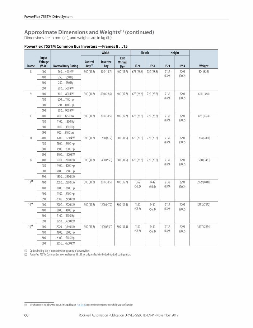
PowerFlex 755TM Drive System
60 Rockwell Automation Publication DRIVES-SG001D-EN-P - November 2019
Approximate Dimensions and Weights(1) (continued) Dimensions are in mm (in.), and weights are in kg (lb).
PowerFlex 755TM Common Bus Inverters —Frames 8 …15
Frame
Input Voltage (V AC) Normal Duty Rating
Width Depth Height
Weight Control
Bay(1)Inverter
Bay
Exit Wiring
Bay IP21 IP54 IP21 IP54
8 400 160…400 kW 300 (11.8) 400 (15.7) 400 (15.7) 675 (26.6) 720 (28.3) 2132 (83.9)
2291 (90.2)
374 (825)
480 250…650 Hp
600 250…550 Hp
690 200…500 kW
9 400 400…800 kW 300 (11.8) 600 (23.6) 400 (15.7) 675 (26.6) 720 (28.3) 2132 (83.9)
2291 (90.2)
611 (1348)
480 650…1100 Hp
600 550…1000 Hp
690 500…900 kW
10 400 800…1250 kW 300 (11.8) 800 (31.5) 400 (15.7) 675 (26.6) 720 (28.3) 2132 (83.9)
2291 (90.2)
873 (1924)
480 1100…1800 Hp
600 1000…1500 Hp
690 900…1400 kW
11 400 1200…1650 kW 300 (11.8) 1200 (47.2) 800 (31.5) 675 (26.6) 720 (28.3) 2132 (83.9)
2291 (90.2)
1284 (2830)
480 1800…2400 Hp
600 1500…2000 Hp
690 1400…1800 kW
12 400 1600…2000 kW 300 (11.8) 1400 (55.1) 800 (31.5) 675 (26.6) 720 (28.3) 2132 (83.9)
2291 (90.2)
1580 (3483)
480 2400…3000 Hp
600 2000…2500 Hp
690 1800…2300 kW
13 (2) 400 2000…2200 kW 300 (11.8) 800 (31.5) 400 (15.7) 1352 (53.2)
1442(56.8)
2132 (83.9)
2291(90.2)
2199 (4848)
480 3000…3600 Hp
600 2500…3100 Hp
690 2300…2750 kW
14 (2) 400 2200…2920 kW 300 (11.8) 1200 (47.2) 800 (31.5) 1352 (53.2)
1442(56.8)
2132 (83.9)
2291(90.2)
3253 (7172)
480 3600…4800 Hp
600 3100…4100 Hp
690 2750…3650 kW
15 (2) 400 2920…3640 kW 300 (11.8) 1400 (55.1) 800 (31.5) 1352 (53.2)
1442(56.8)
2132 (83.9)
2291(90.2)
3607 (7954)
480 4800…6000 Hp
600 4100…5100 Hp
690 3650…4550 kW
(1) Optional wiring bay is not required for top entry of power cables.(2) PowerFlex 755TM Common Bus Inverters Frames 13...15 are only available in the back-to-back configuration.
(1) Weight does not include wiring bays. Refer to publication 750-TD100 to determine the maximum weight for your configuration.

61 Rockwell Automation Publication DRIVES-SG001D-EN-P - November 2019
PowerFlex Drive OptionsHuman Interface Modules
20-HIM-A0 20-HIM-A6
20-HIM-C6S
Description Cat. No.
Used with PowerFlex Common Bus Drive
753/755 755TM
No HIM (Blank Plate), Handheld/Local (Drive Mount) 20-HIM-A0 ✓ ✓
Enhanced, LCD, Full Numeric Keypad, Handheld/Local (Drive Mount) 20-HIM-A6 ✓ ✓
Enhanced, LCD, Full Numeric Keypad(1)(2) 20-HIM-C6S ✓ ✓
Human Interface Module (HIM) Accessories
Description Cat. No.
Used with PowerFlex Common Bus Drive
753/755 755TM
Bezel Kit for LCD HIMs, NEMA Type 1(1) 20-HIM-B1 ✓ ✓
PowerFlex HIM Interface Cable, 1 m (3.3 ft)(2) 20-HIM-H10 ✓ ✓
Comm Option Cable Kit (Male-Male) 0.33 m (1.1 ft) 1202-C03 ✓ ✓ 1 m (3.3 ft) 1202-C10 ✓ ✓ 3 m (9.8 ft) 1202-C30 ✓ ✓ 9 m (29.5 ft) 1202-C90 ✓ ✓
Cable Kit (Male-Female)(3)
0.33 m (1.1 ft) 1202-H03 ✓ ✓ 1 m (3.3 ft) 1202-H10 ✓ ✓ 3 m (9.8 ft) 1202-H30 ✓ ✓ 9 m (29.5 ft) 1202-H90 ✓ ✓
DPI™ Cable Kit with Connectors, Tools and 100 m (328 ft) Cable 1202-CBL-KIT-100M ✓ ✓
DPI Cable Connector Kit 1202-TB-KIT-SET ✓ ✓
DPI/SCANport™ One to Two Port Splitter Cable 1203-S03 ✓ ✓
(1) Includes a 1202-C30 interface cable (3 m/9.8 ft) for connection to drive.(2) Required only when HIM is used as handheld or remote.(3) Required in addition to 20-HIM-H10 for distances up to a total maximum of 10 m (32.8 ft).

PowerFlex Drive Options
Rockwell Automation Publication DRIVES-SG001D-EN-P - November 2019 62
Communication Option Kits and Accessories
Description Cat. No.
Used with PowerFlex Common Bus Drive
753/755 755TM
BACnet/IP Option Module 20-750-BNETIP ✓ —
Coaxial ControlNet™ Option Module 20-750-CNETC ✓ ✓
ControlNet™ Communication Adapter (Coax) 20-COMM-C ✓(1) —
DeviceNet™ Option Module 20-750-DNET ✓ ✓
DeviceNet™ Communication Adapter 20-COMM-D ✓(1) —
Dual-port EtherNet/IP Option Module 20-750-ENETR ✓ ✓
EtherNet/IP™ Communication Adapter 20-COMM-E ✓(1) —
HVAC Communication Adapter 20-COMM-H ✓(1)
CANopen® Communication Adapter 20-COMM-K ✓(1)
LonWorks® Communication Adapter 20-COMM-L ✓(1)
Modbus/TCP Communication Adapter 20-COMM-M ✓(1)
Profibus DPV1 Option Module 20-750-PBUS ✓ (4) ✓
Single-port Profinet I/O Option Module 20-750-PNET ✓ (4) ✓
Dual-port Profinet I/O Option Module 20-750-PNET2P ✓ (4) ✓
PROFIBUS™ DP Communication Adapter 20-COMM-P ✓(1) —
ControlNet™ Communication Adapter (Fiber) 20-COMM-Q ✓(1)
RS485 DF1 Communication Adapter 20-COMM-S ✓(1)
External Communications Kit Power Supply 20-XCOMM-AC-PS1 ✓
DPI External Communications Kit 20-XCOMM-DC-BASE ✓
External DPI I/O Option Board(2) 20-XCOMM-IO-OPT1 ✓
Compact I/O™ Module (3 Channel) 1769-SM1 ✓
Serial Null Modem Adapter 1203-SNM ✓ ✓
Universal Serial Bus Converter(3) 1203-USB ✓ ✓
ControlNet T-tap Straight 1786-TPS ✓ ✓
(1) Requires a Communication Carrier Card (20-750-20COMM or 20-750-20COMM-F1). Refer to the Communication Accessories table on page 63 for details.(2) For use only with DPI External Communications Kits 20-XCOMM-DC-BASE.(3) Includes 2 m USB, 20-HIM-H10 & 22-HIM-H10 cables.(4) Contact your local Allen-Bradley distributor or Rockwell Automation sales office for availability.
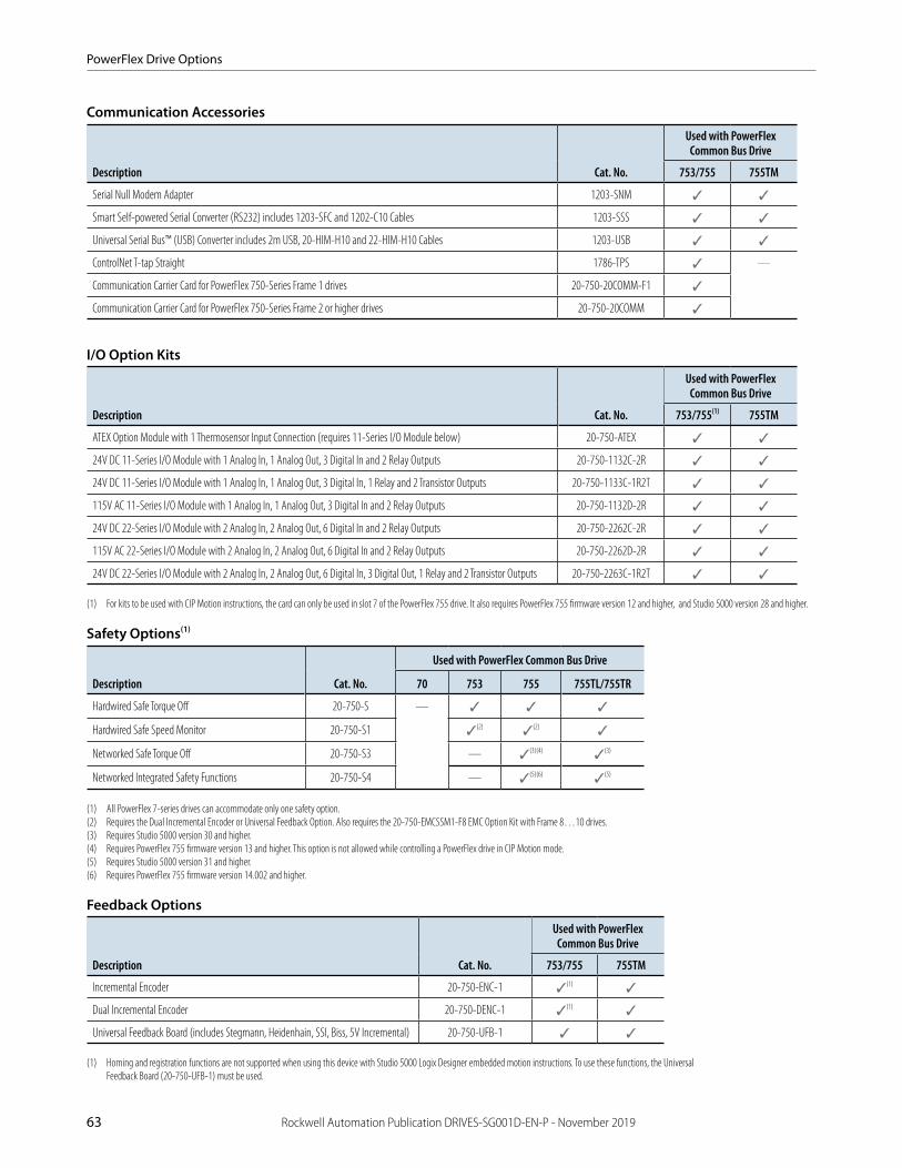
PowerFlex Drive Options
63 Rockwell Automation Publication DRIVES-SG001D-EN-P - November 2019
Communication Accessories
Description Cat. No.
Used with PowerFlex Common Bus Drive
753/755 755TM
Serial Null Modem Adapter 1203-SNM ✓ ✓
Smart Self-powered Serial Converter (RS232) includes 1203-SFC and 1202-C10 Cables 1203-SSS ✓ ✓
Universal Serial Bus™ (USB) Converter includes 2m USB, 20-HIM-H10 and 22-HIM-H10 Cables 1203-USB ✓ ✓
ControlNet T-tap Straight 1786-TPS ✓ —
Communication Carrier Card for PowerFlex 750-Series Frame 1 drives 20-750-20COMM-F1 ✓
Communication Carrier Card for PowerFlex 750-Series Frame 2 or higher drives 20-750-20COMM ✓
I/O Option Kits
Description Cat. No.
Used with PowerFlex Common Bus Drive
753/755(1) 755TM
ATEX Option Module with 1 Thermosensor Input Connection (requires 11-Series I/O Module below) 20-750-ATEX ✓ ✓
24V DC 11-Series I/O Module with 1 Analog In, 1 Analog Out, 3 Digital In and 2 Relay Outputs 20-750-1132C-2R ✓ ✓
24V DC 11-Series I/O Module with 1 Analog In, 1 Analog Out, 3 Digital In, 1 Relay and 2 Transistor Outputs 20-750-1133C-1R2T ✓ ✓
115V AC 11-Series I/O Module with 1 Analog In, 1 Analog Out, 3 Digital In and 2 Relay Outputs 20-750-1132D-2R ✓ ✓
24V DC 22-Series I/O Module with 2 Analog In, 2 Analog Out, 6 Digital In and 2 Relay Outputs 20-750-2262C-2R ✓ ✓
115V AC 22-Series I/O Module with 2 Analog In, 2 Analog Out, 6 Digital In and 2 Relay Outputs 20-750-2262D-2R ✓ ✓
24V DC 22-Series I/O Module with 2 Analog In, 2 Analog Out, 6 Digital In, 3 Digital Out, 1 Relay and 2 Transistor Outputs 20-750-2263C-1R2T ✓ ✓
(1) For kits to be used with CIP Motion instructions, the card can only be used in slot 7 of the PowerFlex 755 drive. It also requires PowerFlex 755 firmware version 12 and higher, and Studio 5000 version 28 and higher.
Safety Options(1)
Description Cat. No.
Used with PowerFlex Common Bus Drive
70 753 755 755TL/755TR
Hardwired Safe Torque Off 20-750-S — ✓ ✓ ✓
Hardwired Safe Speed Monitor 20-750-S1 ✓(2) ✓(2) ✓
Networked Safe Torque Off 20-750-S3 — ✓(3)(4) ✓(3)
Networked Integrated Safety Functions 20-750-S4 — ✓(5)(6) ✓(5)
(1) All PowerFlex 7-series drives can accommodate only one safety option.(2) Requires the Dual Incremental Encoder or Universal Feedback Option. Also requires the 20-750-EMCSSM1-F8 EMC Option Kit with Frame 8…10 drives.(3) Requires Studio 5000 version 30 and higher.(4) Requires PowerFlex 755 firmware version 13 and higher. This option is not allowed while controlling a PowerFlex drive in CIP Motion mode.(5) Requires Studio 5000 version 31 and higher.(6) Requires PowerFlex 755 firmware version 14.002 and higher.
Feedback Options
Description Cat. No.
Used with PowerFlex Common Bus Drive
753/755 755TM
Incremental Encoder 20-750-ENC-1 ✓(1) ✓
Dual Incremental Encoder 20-750-DENC-1 ✓(1) ✓
Universal Feedback Board (includes Stegmann, Heidenhain, SSI, Biss, 5V Incremental) 20-750-UFB-1 ✓ ✓
(1) Homing and registration functions are not supported when using this device with Studio 5000 Logix Designer embedded motion instructions. To use these functions, the Universal Feedback Board (20-750-UFB-1) must be used.
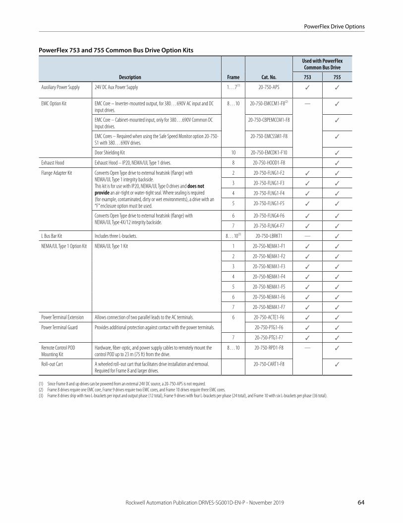
PowerFlex Drive Options
Rockwell Automation Publication DRIVES-SG001D-EN-P - November 2019 64
PowerFlex 753 and 755 Common Bus Drive Option Kits
Description Frame Cat. No.
Used with PowerFlex Common Bus Drive
753 755
Auxiliary Power Supply 24V DC Aux Power Supply 1…7(1) 20-750-APS ✓ ✓
EMC Option Kit EMC Core – Inverter-mounted output, for 380…690V AC input and DC input drives.
8…10 20-750-EMCCM1-F8(2) — ✓
EMC Core – Cabinet-mounted input, only for 380…690V Common DC Input drives.
20-750-CBPEMCCM1-F8 ✓
EMC Cores – Required when using the Safe Speed Monitor option 20-750-S1 with 380…690V drives.
20-750-EMCSSM1-F8 ✓
Door Shielding Kit 10 20-750-EMCDK1-F10 ✓
Exhaust Hood Exhaust Hood – IP20, NEMA/UL Type 1 drives. 8 20-750-HOOD1-F8 ✓
Flange Adapter Kit Converts Open Type drive to external heatsink (flange) with NEMA/UL Type 1 integrity backside. This kit is for use with IP20, NEMA/UL Type 0 drives and does not provide an air-tight or water-tight seal. Where sealing is required (for example, contaminated, dirty or wet environments), a drive with an “F” enclosure option must be used.
2 20-750-FLNG1-F2 ✓ ✓
3 20-750-FLNG1-F3 ✓ ✓
4 20-750-FLNG1-F4 ✓ ✓
5 20-750-FLNG1-F5 ✓ ✓
Converts Open Type drive to external heatsink (flange) with NEMA/UL Type 4X/12 integrity backside.
6 20-750-FLNG4-F6 ✓ ✓
7 20-750-FLNG4-F7 ✓ ✓
L Bus Bar Kit Includes three L-brackets. 8…10(3) 20-750-LBRKT1 — ✓
NEMA/UL Type 1 Option Kit NEMA/UL Type 1 Kit 1 20-750-NEMA1-F1 ✓ ✓
2 20-750-NEMA1-F2 ✓ ✓
3 20-750-NEMA1-F3 ✓ ✓
4 20-750-NEMA1-F4 ✓ ✓
5 20-750-NEMA1-F5 ✓ ✓
6 20-750-NEMA1-F6 ✓ ✓
7 20-750-NEMA1-F7 ✓ ✓
Power Terminal Extension Allows connection of two parallel leads to the AC terminals. 6 20-750-ACTE1-F6 ✓ ✓
Power Terminal Guard Provides additional protection against contact with the power terminals. 20-750-PTG1-F6 ✓ ✓
7 20-750-PTG1-F7 ✓ ✓
Remote Control POD Mounting Kit
Hardware, fiber-optic, and power supply cables to remotely mount the control POD up to 23 m (75 ft) from the drive.
8…10 20-750-RPD1-F8 — ✓
Roll-out Cart A wheeled roll-out cart that facilitates drive installation and removal. Required for Frame 8 and larger drives.
20-750-CART1-F8 ✓
(1) Since Frame 8 and up drives can be powered from an external 24V DC source, a 20-750-APS is not required.(2) Frame 8 drives require one EMC core, Frame 9 drives require two EMC cores, and Frame 10 drives require three EMC cores.(3) Frame 8 drives ship with two L-brackets per input and output phase (12 total), Frame 9 drives with four L-brackets per phase (24 total), and Frame 10 with six L-brackets per phase (36 total).
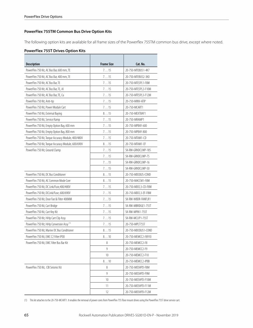
PowerFlex Drive Options
65 Rockwell Automation Publication DRIVES-SG001D-EN-P - November 2019
PowerFlex 755TM Common Bus Drive Option Kits
The following option kits are available for all frame sizes of the Powerflex 755TM common bus drive, except where noted.
PowerFlex 755T Drives Option Kits
Description Frame Size Cat. No.
PowerFlex 750 Kit, AC Bus Bar, 600 mm, TE 7…15 20-750-MTEBUS1-4K7
PowerFlex 750 Kit, AC Bus Bar, 400 mm, TE 7…15 20-750-MTEBUS2-3K0
PowerFlex 750 Kit, AC Bus Bar, TE 7…15 20-750-MTESPL1-F8M
PowerFlex 750 Kit, AC Bus Bar, TE, Al 7…15 20-750-MTESPL2-F10M
PowerFlex 750 Kit, AC Bus Bar, TE, Cu 7…15 20-750-MTESPL3-F12M
PowerFlex 750 Kit, Anti-tip 7…15 20-750-MINV-ATIP
PowerFlex 750 Kit, Power Module Cart 7…15 20-750-MCART1
PowerFlex 750 Kit, External Baying 8…15 20-750-MEXTBAY1
PowerFlex 750 Kit, Service Ramp 7…15 20-750-MRAMP1
PowerFlex 750 Kit, Empty Option Bay, 600 mm 7…15 20-750-MPBAY-600
PowerFlex 750 Kit, Empty Option Bay, 800 mm 7…15 20-750-MPBAY-800
PowerFlex 750 Kit, Torque Accuracy Module, 400/480V 7…15 20-750-MTAM1-CD
PowerFlex 750 Kit, Torque Accuracy Module, 600/690V 8…15 20-750-MTAM1-EF
PowerFlex 750 Kit, Ground Clamp 7…15 SK-RM-GRNDCLMP-185
7…15 SK-RM-GRNDCLMP-75
7…15 SK-RM-GRNDCLMP-16
7…15 SK-RM-GRNDCLMP-50
PowerFlex 750 Kit, DC Bus Conditioner 8…15 20-750-MDCBUS-COND
PowerFlex 750 Kit, AC Common Mode Core 8…15 20-750-MACCM1-F8M
PowerFlex 750 Kit, DC Link/Fuse,400/480V 7…15 20-750-MDCL3-CD-F8M
PowerFlex 750 Kit, DCLink/Fuse, 600/690V 7…15 20-750-MDCL3-EF-F8M
PowerFlex 750 Kit, Door Fan & Filter 400MM 7…15 SK-RM-WBDR-FANFLR1
PowerFlex 750 Kit, Cart Bridge 7…15 SK-RM-MBRIDGE1-755T
PowerFlex 750 Kit, Cart Key Kit 7…15 SK-RM-MPIN1-755T
PowerFlex 750 Kit, HiHp Cart Clip Assy 7…15 SK-RM-MCLIP1-755T
PowerFlex 750 Kit, HiHp Conversion Assy (1) 7…15 20-750-MPLT755T
PowerFlex 750 Kit, Marine DC Bus Conditioner 8…15 20-750-MDCBUS1-COND
PowerFlex 750 Kit, EMC C2 Filter IP00 8…10 20-750-MEMCC2-F8910
PowerFlex 750 Kit, EMC Filter Bus Bar Kit 8 20-750-MEMCC2-F8
9 20-750-MEMCC2-F9
10 20-750-MEMCC2-F10
8…10 20-750-MEMCC2-IPBB
PowerFlex 750 Kit, CBI Seismic Kit 8 20-750-MOSHPD-F8M
9 20-750-MOSHPD-F9M
10 20-750-MOSHPD-F10M
11 20-750-MOSHPD-F11M
12 20-750-MOSHPD-F12M
(1) This kit attaches to the 20-750-MCART1. It enables the removal of power cores from PowerFlex 755 floor mount drives using the PowerFlex 755T drive service cart.
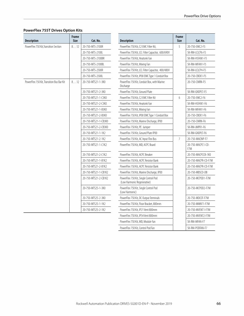
PowerFlex Drive Options
Rockwell Automation Publication DRIVES-SG001D-EN-P - November 2019 66
PowerFlex 755T Drives Option Kits
DescriptionFrame
Size Cat. No. DescriptionFrame
Size Cat. No.
PowerFlex 750 Kit,Transition Section 8…12 20-750-MTS-2100R PowerFlex 750 Kit, C2 EMC Filter Kit, 5 20-750-EMC2-F5
20-750-MTS-2100L PowerFlex 750 Kit, LCL Filter Capacitor, 600/690V SK-RM-LCLCP6-F5
20-750-MTS-2100BR PowerFlex 750 Kit, Heatsink Fan SK-RM-HSFAN1-F5
20-750-MTS-2100BL PowerFlex 750 Kit, Mixing Fan SK-RM-MFAN1-F5
20-750-MTS-2500R PowerFlex 750 Kit, LCL Filter Capacitor, 400/480V SK-RM-LCLCP4-F5
20-750-MTS-2500L PowerFlex 750 Kit, IP00 EMC Type 1 Conduit Box 20-750-CBOX1-F5
PowerFlex 750 Kit, Transition Bus Bar Kit 8…12 20-750-MTS21-1-3K0 PowerFlex 750 Kit, Conduit Box, with Marine Discharge
20-750-CMRN-F5
20-750-MTS21-2-3K0 PowerFlex 750 Kit, Ground Plate SK-RM-GNDPLT-F5
20-750-MTS21-1-C3K0 PowerFlex 750 Kit, C2 EMC Filter Kit 6 20-750-EMC2-F6
20-750-MTS21-2-C3K0 PowerFlex 750 Kit, Heatsink Fan SK-RM-HSFAN1-F6
20-750-MTS21-1-B3K0 PowerFlex 750 Kit, Mixing Fan SK-RM-MFAN1-F6
20-750-MTS21-2-B3K0 PowerFlex 750 Kit, IP00 EMC Type 1 Conduit Box 20-750-CBOX1-F6
20-750-MTS21-1-CB3K0 PowerFlex 750 Kit, Marine Discharge, IP00 20-750-CMRN-F6
20-750-MTS21-2-CB3K0 PowerFlex 750 Kit, PE Jumper SK-RM-JMPR1-F6
20-750-MTS21-1-1K2 PowerFlex 750 Kit, Ground Plate IP00 SK-RM-GNDPLT-F6
20-750-MTS21-2-1K2 PowerFlex 750 Kit, AC Input Flex Bus 7 20-750-MACINP-F7
20-750-MTS21-1-C1K2 PowerFlex 750 Kit, MD, ACPC Board 20-750-MACPC1-CD-F7M
20-750-MTS21-2-C1K2 PowerFlex 750 Kit, ACPC Breaker 20-750-MACPCCB-1K0
20-750-MTS21-1-B1K2 PowerFlex 750 Kit, ACPC Resistor Bank 20-750-MACPR-CD-F7M
20-750-MTS21-2-B1K2 PowerFlex 750 Kit, ACPC Resistor Bank 20-750-MACPR-CD-F7M
20-750-MTS21-1-CB1K2 PowerFlex 750 Kit, Marine Discharge, IP00 20-750-MBSCD-DB
20-750-MTS21-2-CB1K2 PowerFlex 750 Kit, Single Control Pod (Low Harmonic Regenerative)
20-750-MCPOD1-F7M
20-750-MTS25-1-3K0 PowerFlex 750 Kit, Single Control Pod (Low Harmonic)
20-750-MCPOD2-F7M
20-750-MTS25-2-3K0 PowerFlex 750 Kit, DC Output Terminals 20-750-MDCOT-F7M
20-750-MTS25-1-1K2 PowerFlex 750 Kit, Floor Bracket, 800mm 20-750-MMNT1-F7M
20-750-MTS25-2-1K2 PowerFlex 750 Kit, IP21 Vent 800mm 20-750-MVENT1-F7M
PowerFlex 750 Kit, IP54 Vent 800mm 20-750-MVENT2-F7M
PowerFlex 750 Kit, MD, Module Fan SK-RM-MFAN-F7
PowerFlex 750 Kit, Control Pod Fan SK-RM-PODFAN-F7

PowerFlex Drive Options
67 Rockwell Automation Publication DRIVES-SG001D-EN-P - November 2019
PowerFlex 753 and 755 Reflected Wave Reduction Modules
If you need a reflective wave reduction module for a 932V DC input PowerFlex 750-series drive, contact your local Rockwell Automation sales office or your Allen-Bradley distributor.
Drive Input Voltage
Normal Duty
Cat. No. 753/755kW Hp
540…650V DC 4 5 1321-RWR8-DP ✓
5.5 7.5 1321-RWR12-DP ✓
7.5 10 1321-RWR18-DP ✓
11 15 1321-RWR25-DP ✓
15 20 1321-RWR35-DP ✓
18.5 25 1321-RWR35-DP ✓
22 30 1321-RWR45-DP ✓
30 40 1321-RWR55-DP ✓
37 50 1321-RWR80-DP ✓
45 60 1321-RWR80-DP ✓
55 75 1321-RWR100-DP ✓
75 100 1321-RWR130-DP ✓
90 125 1321-RWR160-DP ✓
110 150 1321-RWR200-DP ✓
149 200 1321-RWR250-DP ✓
187 250 1321-RWR320-DP ✓
810V DC 4 5 1321-RWR8-EP ✓
5.5 7.5 1321-RWR12-EP ✓
7.5 10 1321-RWR12-EP —
1321-RWR18-EP ✓
11 15 1321-RWR18-EP —
1321-RWR25-EP ✓
15 20 1321-RWR25-EP —
1321-RWR35-EP ✓
18.5 25 1321-RWR35-EP ✓
22 30 1321-RWR35-EP —
1321-RWR45-EP ✓
30 40 1321-RWR45-EP —
1321-RWR55-EP ✓
37 50 1321-RWR55-EP —
1321-RWR80-EP ✓
45 60 1321-RWR80-EP ✓
55 75 1321-RWR100-EP ✓
75 100 1321-RWR130-EP ✓
90 125 1321-RWR160-EP ✓
110 150 1321-RWR200-EP ✓
149 200 1321-RWR250-EP ✓

PowerFlex Drive Options
Rockwell Automation Publication DRIVES-SG001D-EN-P - November 2019 68
PowerFlex 753 and 755 Input and Output Reactors–540V DC Nominal Input, 3% Impedance
kW Hp Duty
Input Line Reactor(1) Output Reactor(1)
753/755IP00 (Open Style) IP11 (NEMA/UL Type 1) IP00 (Open Style) IP11 (NEMA/UL Type 1)
0.25 0.33 Heavy 1321-3R1-C 1321-3RA1-C 1321-3R2-B 1321-3RA2-B —
0.37 0.5 Normal
0.55 0.75 Heavy 1321-3R2-A 1321-3RA2-A 1321-3R2-A 1321-3RA2-A
0.75 1 Normal ✓
1.1 1.5 Heavy 1321-3R4-C 1321-3RA4-C 1321-3R4-B 1321-3RA4-B ✓
1.5 2 Normal 1321-3R4-B 1321-3RA4-B ✓
Heavy 1321-3R8-C 1321-3RA8-C ✓
2.2 3 Normal 1321-3R8-C 1321-3RA8-C ✓
Heavy 1321-3R8-B 1321-3RA8-B ✓
4 5 Normal 1321-3R8-B 1321-3RA8-B ✓
Heavy 1321-3R12-B 1321-3RA12-B ✓
5.5 7.5 Normal 1321-3R12-B 1321-3RA12-B ✓
Heavy 1321-3R18-B 1321-3RA18-B ✓
7.5 10 Normal 1321-3R18-B 1321-3RA18-B ✓
Heavy 1321-3R25-B 1321-3RA25-B ✓
11 15 Normal 1321-3R25-B 1321-3RA25-B ✓
Heavy ✓
15 20 Normal 1321-3R35-B 1321-3RA35-B ✓
Heavy 1321-3R35-B 1321-3RA35-B ✓
18.5 25 Normal ✓
Heavy 1321-3R45-B 1321-3RA45-B ✓
22 30 Normal 1321-3R45-B 1321-3RA45-B ✓
Heavy 1321-3R55-B 1321-3RA55-B ✓
30 40 Normal 1321-3R55-B 1321-3RA55-B ✓
Heavy 1321-3R80-B 1321-3RA80-B ✓
37 50 Normal 1321-3R80-B 1321-3RA80-B ✓
Heavy ✓
45 60 Normal/Heavy ✓
55 75 1321-3R100-B 1321-3RA100-B 1321-3R100-B 1321-3RA100-B ✓
75 100 1321-3R130-B 1321-3RA130-B 1321-3R130-B 1321-3RA130-B ✓
90 125 1321-3R160-B 1321-3RA160-B 1321-3R160-B 1321-3RA160-B ✓
110 150 Normal 1321-3R200-B 1321-3RA200-B 1321-3R200-C 1321-3RA200-C ✓
Heavy ✓
— 200 Normal/Heavy 1321-3RB250-B 1321-3RAB250-B 1321-3RB250-B 1321-3RAB250-B ✓
132 — ✓
160 250 1321-3RB320-B 1321-3RAB320-B 1321-3RB320-B 1321-3RAB320-B ✓
(1) Input line reactors were sized based on the NEC fundamental motor amps. Output line reactors were sized based on the VFD rated output currents.
(table continues on next page)

PowerFlex Drive Options
69 Rockwell Automation Publication DRIVES-SG001D-EN-P - November 2019
PowerFlex 753 and 755 Input and Output Reactors–540V DC Nominal Input, 3% Impedance (continued)
kW Hp Duty(2)
Input Line Reactor(1) Output Reactor(1)
753/755IP00 (Open Style) IP11 (NEMA/UL Type 1) IP00 (Open Style) IP11 (NEMA/UL Type 1)
200 300 Normal 1321-3RB400-B 1321-3RAB400-B 1321-3RB400-B 1321-3RAB400-B ✓
Heavy ✓
— 350 Normal/Heavy 1321-3R500-B 1321-3R500-B 1321-3R500-B 1321-3R500-B ✓
250 — 1321-3RA500-B 1321-3RA500-B ✓
— 400 Light/Normal/Heavy 1321-3R500-B 1321-3RA500-B 1321-3R500-B 1321-3RA500-B ✓
315 — 1321-3R600-B 1321-3RA600-B 1321-3R600-B 1321-3RA600-B ✓
— 450 ✓
355 — 1321-3R750-B 1321-3RA750-B 1321-3R750-B 1321-3RA750-B ✓
— 500 Light 1321-3R600-B 1321-3RA600-B 1321-3R600-B 1321-3RA600-B ✓
Normal/Heavy 1321-3R750-B 1321-3RA750-B 1321-3R750-B 1321-3RA750-B ✓
400 — Light/Heavy ✓
Normal 1321-3R850-B 1321-3RA850-B 1321-3R850-B 1321-3RA850-B ✓
— 600 Light/Normal/Heavy 1321-3R750-B 1321-3RA750-B 1321-3R750-B 1321-3RA750-B ✓
450 — Light 1321-3R850-B 1321-3RA850-B 1321-3R850-B 1321-3RA850-B ✓
— 650 ✓
Normal 1321-3R750-B 1321-3RA750-B 1321-3R750-B 1321-3RA750-B ✓
— 700 Light/Normal/Heavy 1321-3R850-B 1321-3RA850-B 1321-3R850-B 1321-3RA850-B ✓
— 750 Heavy ✓
500 — Normal/Heavy 1321-3R1000-B 1321-3RA1000-B 1321-3R1000-B 1321-3RA1000-B ✓
— 800 Light/Normal/Heavy ✓
560 — 1321-3R600-B 1321-3RA600-B 1321-3R600-B 1321-3RA600-B ✓(3)
630 900 1321-3R600-B 1321-3RA600-B ✓(3)
710 1000 ✓(3)
800 1100 Light/Normal 1321-3R750-B 1321-3RA750-B 1321-3R750-B 1321-3RA750-B ✓(3)
850 — ✓(3)
900 — Light 1321-3R850-B 1321-3RA850-B 1321-3R850-B 1321-3RA850-B ✓(3)
— 1250 Light/Normal 1321-3R750-B 1321-3RA750-B 1321-3R750-B 1321-3RA750-B ✓(3)
— 1350 Light 1321-3R850-B 1321-3RA850-B 1321-3R850-B 1321-3RA850-B ✓(3)
— 1500 ✓(4)
1000 — ✓(4)
— 2000 ✓(4)
1400 — ✓(4)
(1) Input line reactors were sized based on the NEC fundamental motor amps. Output line reactors were sized based on the VFD rated output currents.(2) Light Duty refers only to PowerFlex 755 drives.(3) Requires two reactors wired in parallel.(4) Requires three reactors wired in parallel.

PowerFlex Drive Options
Rockwell Automation Publication DRIVES-SG001D-EN-P - November 2019 70
PowerFlex 753 and 755 Input and Output Reactors–650V DC Nominal Input, 5% Impedance
kW Hp Duty
Input Line Reactor(1) Output Reactor(1)
753/755IP00 (Open Style) IP11 (NEMA/UL Type 1) IP00 (Open Style) IP11 (NEMA/UL Type 1)
0.25 0.33 Heavy 1321-3R1-B 1321-3RA1-B 1321-3R2-C 1321-3RA2-C —
0.37 0.5 Normal
0.55 0.75 Heavy 1321-3R2-C 1321-3RA2-C 1321-3R2-B 1321-3RA2-B
0.75 1 Normal 1321-3R2-B 1321-3RA2-B ✓
1.1 1.5 Heavy 1321-3R4-D 1321-3RA4-D 1321-3R4-D 1321-3RA4-D ✓
1.5 2 Normal ✓
Heavy 1321-3R8-D 1321-3RA8-D ✓
2.2 3 Normal 1321-3R8-D 1321-3RA8-D ✓
Heavy 1321-3R8-C 1321-3RA8-C ✓
4 5 Normal 1321-3R8-C 1321-3RA8-C ✓
Heavy 1321-3R12-C 1321-3RA12-C ✓
5.5 7.5 Normal 1321-3R12-C 1321-3RA12-C ✓
Heavy 1321-3R18-C 1321-3RA18-C ✓
7.5 10 Normal 1321-3R18-C 1321-3RA18-C ✓
Heavy 1321-3R25-C 1321-3RA25-C ✓
11 15 Normal/Heavy 1321-3R25-C 1321-3RA25-C ✓
15 20 Normal 1321-3RA35-C 1321-3R25-C 1321-3RA25-C ✓
Heavy 1321-3R35-C 1321-3R35-C 1321-3RA35-C ✓
18.5 25 Normal ✓
Heavy 1321-3R45-C 1321-3RA45-C ✓
22 30 Normal 1321-3R45-C 1321-3RA45-C ✓
Heavy 1321-3R55-C 1321-3RA55-C ✓
30 40 Normal 1321-3R55-C 1321-3RA55-C ✓
Heavy 1321-3R80-C 1321-3RA80-C ✓
37 50 Normal 1321-3R80-C 1321-3RA80-C ✓
Heavy ✓
45 60 Normal/Heavy ✓
55 75 1321-3R100-C 1321-3RA100-C 1321-3R100-C 1321-3RA100-C ✓
75 100 1321-3R130-C 1321-3RA130-C 1321-3R130-C 1321-3RA130-C ✓
90 125 1321-3R160-C 1321-3RA160-C 1321-3R160-C 1321-3RA160-C ✓
110 150 Normal 1321-3R200-C 1321-3RA200-C 1321-3R200-C 1321-3RA200-C ✓
Heavy ✓
(1) Input line reactors were sized based on the NEC fundamental motor amps. Output line reactors were sized based on the VFD rated output currents.
(table continues on next page)

PowerFlex Drive Options
71 Rockwell Automation Publication DRIVES-SG001D-EN-P - November 2019
PowerFlex 753 and 755 Input and Output Reactors–650V DC Nominal Input, 5% Impedance (continued)
kW Hp Duty(2)
Input Line Reactor(1) Output Reactor(1)
753/755IP00 (Open Style) IP11 (NEMA/UL Type 1) IP00 (Open Style) IP11 (NEMA/UL Type 1)
— 200 Normal/Heavy 1321-3RB250-C 1321-3RAB250-C 1321-3RB250-C 1321-3RAB250-C ✓
132 — 1321-3RB320-C 1321-3RAB320-C 1321-3RB320-C 1321-3RAB320-C ✓
160 250 ✓
— 300 1321-3RB400-C 1321-3RAB400-C 1321-3RB400-C 1321-3RAB400-C ✓
200 — ✓
— 350 1321-3R500-C 1321-3R500-C 1321-3R500-C 1321-3R500-C ✓
250 — 1321-3RA500-C 1321-3R500-C 1321-3RA500-C ✓
— 400 Light/Normal/Heavy 1321-3R500-C 1321-3RA500-C 1321-3R500-C 1321-3RA500-C ✓
315 — 1321-3R600-C 1321-3RA600-C 1321-3R600-C 1321-3RA600-C ✓
— 450 ✓
355 — 1321-3R750-C 1321-3RA750-C 1321-3R750-C 1321-3RA750-C ✓
— 500 Light 1321-3R600-C 1321-3RA600-C 1321-3R600-C 1321-3RA600-C ✓
Normal/Heavy 1321-3R750-C 1321-3RA750-C 1321-3R750-C 1321-3RA750-C ✓
400 — Light/Heavy ✓
Normal 1321-3R850-C 1321-3RA850-C 1321-3R850-C 1321-3RA850-C ✓
— 600 Light/Normal/Heavy 1321-3R750-C 1321-3RA750-C 1321-3R750-C 1321-3RA750-C ✓
450 — Light 1321-3R850-C 1321-3RA850-C 1321-3R850-C 1321-3RA850-C ✓
500 — Normal/Heavy 1321-3R1000-C 1321-3RA1000-C 1321-3R1000-C 1321-3RA1000-C ✓
— 650 Light 1321-3R850-C 1321-3RA850-C 1321-3R850-C 1321-3RA850-C ✓
Normal 1321-3R750-C 1321-3RA750-C 1321-3R750-C 1321-3RA750-C ✓
— 700 Light/Normal/Heavy 1321-3R850-C 1321-3RA850-C 1321-3R850-C 1321-3RA850-C ✓
— 750 Heavy ✓
— 800 Light/Normal/Heavy 1321-3R1000-C 1321-3RA1000-C 1321-3R1000-C 1321-3RA1000-C ✓
560 — 1321-3R600-C 1321-3RA600-C 1321-3R600-C 1321-3RA600-C ✓(3)
630 — ✓(3)
— 900 ✓(3)
710 — ✓(3)
— 1000 ✓(3)
— 1100 Light/Normal 1321-3R750-C 1321-3RA750-C 1321-3R750-C 1321-3RA750-C ✓(3)
800 — ✓(3)
850 — ✓(3)
— 1250 ✓(3)
900 — Light 1321-3R850-C 1321-3RA850-C 1321-3R850-C 1321-3RA850-C ✓(3)
— 1350 ✓(3)
— 1500 ✓(4)
1000 — ✓(4)
— 2000 ✓(4)
1400 — ✓(4)
(1) Input line reactors were sized based on the NEC fundamental motor amps. Output line reactors were sized based on the VFD rated output currents.(2) Light Duty refers only to PowerFlex 755 drives.(3) Requires two output reactors wired in parallel.(4) Requires three reactors wired in parallel.

PowerFlex Drive Options
Rockwell Automation Publication DRIVES-SG001D-EN-P - November 2019 72
PowerFlex 753 and 755 Input and Output Reactors–810V DC Nominal Input, 3% Impedance
kW Hp Duty
Input Line Reactor(1) Output Reactor(1)
753/755IP00 (Open Style) IP11 (NEMA/UL Type 1) IP00 (Open Style) IP11 (NEMA/UL Type 1)
0.75 1 Normal 1321-3R2-B(2) 1321-3RA2-B(2) 1321-3R2-B(2) 1321-3RA2-B(2)✓
Heavy 1321-3R4-D(2) 1321-3RA4-D(2)✓
1.1 1.5 1321-3R2-A(2) 1321-3RA2-A(2) —
1.5 2 Normal 1321-3R4-C(2) 1321-3RA4-C(2) 1321-3RA4-D(2)
Heavy 1321-3R4-C(2) 1321-3RA4-C(2)✓
Normal 1321-3R4-D(2) 1321-3RA4-D(2) 1321-3R4-D(2) 1321-3RA4-D(2)✓
Heavy 1321-3R4-C(2) 1321-3RA4-C(2)✓
2.2 3 Normal 1321-3R4-C(2) 1321-3RA4-C(2)✓
Heavy 1321-3R8-C(2) 1321-3RA8-C(2) —
4 5 Normal 1321-3R8-C(2) 1321-3RA8-C(2)✓
Heavy 1321-3R12-C(2) 1321-3RA12-C(2)✓
5.5 7.5 Normal 1321-3R12-C(2) 1321-3RA12-C(2)✓
Heavy 1321-3R12-B(2) 1321-3RA12-B(2)✓
7.5 10 Normal 1321-3R12-B(2) 1321-3RA12-B(2)✓
Heavy 1321-3R18-B(2) 1321-3RA18-B(2)✓
11 15 Normal 1321-3R18-B(2) 1321-3RA18-B(2)✓
Heavy 1321-3R25-B(2) 1321-3RA25-B(2)✓
15 20 Normal 1321-3R25-B(2) 1321-3RA25-B(2)✓
Heavy 1321-3R35-C(2) 1321-3RA35-C(2)✓
18.5 25 Normal 1321-3R35-C(2) 1321-3RA35-C(2)✓
Heavy 1321-3R35-B(2) 1321-3RA35-B(2)✓
22 30 Normal 1321-3R35-B(2) 1321-3RA35-B(2)✓
Heavy 1321-3R45-B(2) 1321-3RA45-B(2)✓
30 40 Normal 1321-3R45-B(2) 1321-3RA45-B(2)✓
Heavy 1321-3R55-B(2) 1321-3RA55-B(2)✓
37 50 Normal 1321-3R55-B 1321-3RA55-B 1321-3R55-B 1321-3RA55-B ✓
Heavy 1321-3R80-B 1321-3RA80-B ✓
45 60 Normal/Heavy 1321-3R80-B 1321-3RA80-B ✓
55 75 ✓
75 100 1321-3R100-B 1321-3RA100-B 1321-3R100-B 1321-3RA100-B ✓
90 125 1321-3R130-B 1321-3RA130-B 1321-3R130-B 1321-3RA130-B ✓
(1) Input line reactors were sized based on the NEC fundamental motor amps. Output line reactors were sized based on the VFD rated output currents.(2) Only rated for 810V DC and cannot be used on the same common DC bus as 810/932V DC applications.
(table continues on next page)

PowerFlex Drive Options
73 Rockwell Automation Publication DRIVES-SG001D-EN-P - November 2019
PowerFlex 753 and 755 Input and Output Reactors–810V DC Nominal Input, 3% Impedance (continued)
kW Hp Duty
Input Line Reactor(1) Output Reactor(1)
753/755IP00 (Open Style) IP11 (NEMA/UL Type 1) IP00 (Open Style) IP11 (NEMA/UL Type 1)
110 150 Normal 1321-3R160-B 1321-3RA160-B 1321-3R160-B 1321-3RA160-B ✓
— 300 Heavy 1321-3RB320-B 1321-3RAB320-B 1321-3RB320-B 1321-3RAB320-B ✓
200 — 1321-3R250-B 1321-3RA250-B 1321-3R250-B 1321-3RA250-B ✓
— 350 Light/Normal/Heavy 1321-3RB400-B 1321-3RAB400-B 1321-3RB400-B 1321-3RAB400-B ✓
250 — Normal/Heavy 1321-3RB320-B 1321-3RAB320-B 1321-3RB320-B 1321-3RAB320-B ✓
— 400 Light/Normal/Heavy 1321-3RB400-B 1321-3RAB400-B 1321-3RB400-B 1321-3RAB400-B ✓
300 — Heavy ✓
— 450 Light/Normal/Heavy 1321-3R500-B 1321-3RA500-B 1321-3R500-B 1321-3RA500-B ✓
315 — Light/Normal 1321-3RB400-B 1321-3RAB400-B 1321-3RB400-B 1321-3RAB400-B ✓
— 500 Light/Normal/Heavy 1321-3R600-B 1321-3RA600-B 1321-3R600-B 1321-3RA600-B ✓
355 — 1321-3R500-B 1321-3RA500-B 1321-3R500-B 1321-3RA500-B ✓
— 550 Light 1321-3R600-B 1321-3RA600-B 1321-3R600-B 1321-3RA600-B ✓
375 — Heavy 1321-3R500-B 1321-3RA500-B 1321-3R500-B 1321-3RA500-B ✓
400 Light/Normal/Heavy ✓
— 600 Normal/Heavy 1321-3R600-B 1321-3RA600-B 1321-3R600-B 1321-3RA600-B ✓
450 — Light/Normal ✓
500 Light/Normal/Heavy 1321-3R600-B ✓
— 700 1321-3R750-B 1321-3RA750-B 1321-3R750-B 1321-3RA750-B ✓
530 — Light 1321-3R600-B 1321-3RA600-B 1321-3R600-B 1321-3RA600-B ✓
560 Normal/Heavy 1321-3R750-B 1321-3RA750-B 1321-3R750-B 1321-3RA750-B ✓
— 750 Heavy ✓
800 Light/Normal/Heavy 1321-3R850-B 1321-3RA850-B 1321-3R850-B 1321-3RA850-B ✓
630 — 1321-3R750-B 1321-3RA750-B 1321-3R750-B 1321-3RA750-B ✓
— 900 1321-3R850-B 1321-3RA850-B 1321-3R850-B 1321-3RA850-B ✓
710 — ✓
— 950 Light/Normal 1321-3R1000-B 1321-3RA1000-B 1321-3R1000-B 1321-3RA1000-B ✓
750 — Normal 1321-3R850-B 1321-3RA850-B 1321-3R850-B 1321-3RA850-B ✓
800 Light/Normal/Heavy 1321-3R1000-B 1321-3RA1000-B 1321-3R1000-B 1321-3RA1000-B ✓
— 1000 Light/Normal ✓
1100 Light 1321-3R600-B 1321-3RA600-B 1321-3R600-B 1321-3RA600-B ✓(2)
850 — 1321-3R1000-B 1321-3RA1000-B 1321-3R1000-B 1321-3RA1000-B ✓
900 Light/Normal 1321-3R600-B 1321-3RA600-B 1321-3R600-B 1321-3RA600-B ✓(2)
1000 Light 1321-3R600-B 1321-3RA600-B ✓(2)
1100 Light/Normal ✓(3)
— 1200 Light ✓(3)
1500 — Light/Normal ✓(3)
— 1500 Light ✓(3)
(1) Input line reactors were sized based on the NEC fundamental motor amps. Output line reactors were sized based on the VFD rated output currents.(2) Requires two reactors wired in parallel. (3) Requires three reactors wired in parallel.
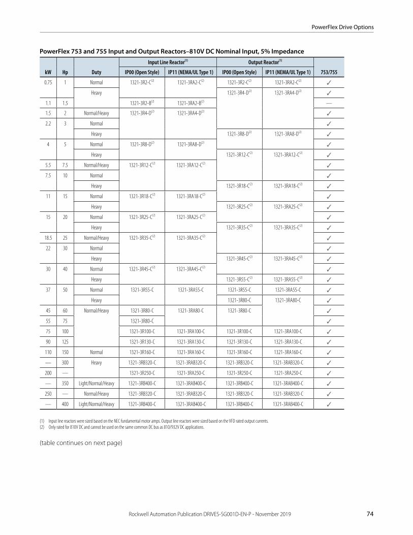
PowerFlex Drive Options
Rockwell Automation Publication DRIVES-SG001D-EN-P - November 2019 74
PowerFlex 753 and 755 Input and Output Reactors–810V DC Nominal Input, 5% Impedance
kW Hp Duty
Input Line Reactor(1) Output Reactor(1)
753/755IP00 (Open Style) IP11 (NEMA/UL Type 1) IP00 (Open Style) IP11 (NEMA/UL Type 1)
0.75 1 Normal 1321-3R2-C(2) 1321-3RA2-C(2) 1321-3R2-C(2) 1321-3RA2-C(2)✓
Heavy 1321-3R4-D(2) 1321-3RA4-D(2)✓
1.1 1.5 1321-3R2-B(2) 1321-3RA2-B(2) —
1.5 2 Normal/Heavy 1321-3R4-D(2) 1321-3RA4-D(2)✓
2.2 3 Normal ✓
Heavy 1321-3R8-D(2) 1321-3RA8-D(2)✓
4 5 Normal 1321-3R8-D(2) 1321-3RA8-D(2)✓
Heavy 1321-3R12-C(2) 1321-3RA12-C(2)✓
5.5 7.5 Normal/Heavy 1321-3R12-C(2) 1321-3RA12-C(2)✓
7.5 10 Normal ✓
Heavy 1321-3R18-C(2) 1321-3RA18-C(2)✓
11 15 Normal 1321-3R18-C(2) 1321-3RA18-C(2)✓
Heavy 1321-3R25-C(2) 1321-3RA25-C(2)✓
15 20 Normal 1321-3R25-C(2) 1321-3RA25-C(2)✓
Heavy 1321-3R35-C(2) 1321-3RA35-C(2)✓
18.5 25 Normal/Heavy 1321-3R35-C(2) 1321-3RA35-C(2)✓
22 30 Normal ✓
Heavy 1321-3R45-C(2) 1321-3RA45-C(2)✓
30 40 Normal 1321-3R45-C(2) 1321-3RA45-C(2)✓
Heavy 1321-3R55-C(2) 1321-3RA55-C(2)✓
37 50 Normal 1321-3R55-C 1321-3RA55-C 1321-3R55-C 1321-3RA55-C ✓
Heavy 1321-3R80-C 1321-3RA80-C ✓
45 60 Normal/Heavy 1321-3R80-C 1321-3RA80-C 1321-3R80-C ✓
55 75 1321-3R80-C ✓
75 100 1321-3R100-C 1321-3RA100-C 1321-3R100-C 1321-3RA100-C ✓
90 125 1321-3R130-C 1321-3RA130-C 1321-3R130-C 1321-3RA130-C ✓
110 150 Normal 1321-3R160-C 1321-3RA160-C 1321-3R160-C 1321-3RA160-C ✓
— 300 Heavy 1321-3RB320-C 1321-3RAB320-C 1321-3RB320-C 1321-3RAB320-C ✓
200 — 1321-3R250-C 1321-3RA250-C 1321-3R250-C 1321-3RA250-C ✓
— 350 Light/Normal/Heavy 1321-3RB400-C 1321-3RAB400-C 1321-3RB400-C 1321-3RAB400-C ✓
250 — Normal/Heavy 1321-3RB320-C 1321-3RAB320-C 1321-3RB320-C 1321-3RAB320-C ✓
— 400 Light/Normal/Heavy 1321-3RB400-C 1321-3RAB400-C 1321-3RB400-C 1321-3RAB400-C ✓
(1) Input line reactors were sized based on the NEC fundamental motor amps. Output line reactors were sized based on the VFD rated output currents.(2) Only rated for 810V DC and cannot be used on the same common DC bus as 810/932V DC applications.
(table continues on next page)
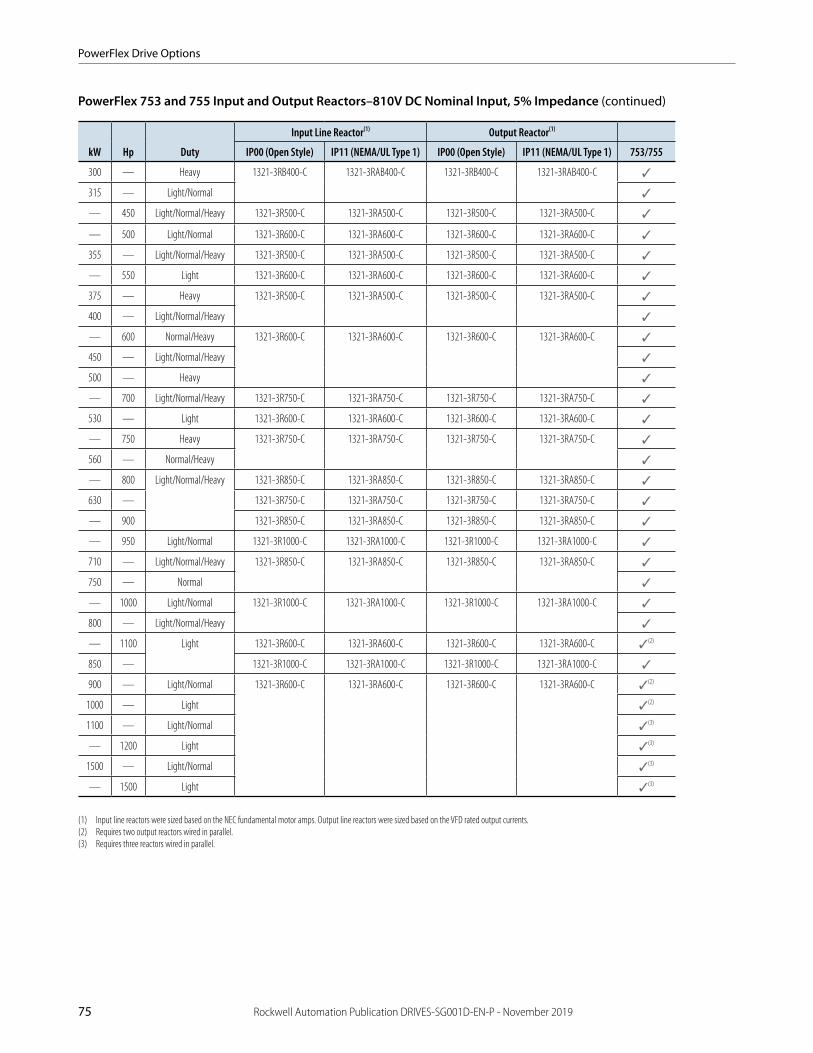
PowerFlex Drive Options
75 Rockwell Automation Publication DRIVES-SG001D-EN-P - November 2019
PowerFlex 753 and 755 Input and Output Reactors–810V DC Nominal Input, 5% Impedance (continued)
kW Hp Duty
Input Line Reactor(1) Output Reactor(1)
IP00 (Open Style) IP11 (NEMA/UL Type 1) IP00 (Open Style) IP11 (NEMA/UL Type 1) 753/755
300 — Heavy 1321-3RB400-C 1321-3RAB400-C 1321-3RB400-C 1321-3RAB400-C ✓
315 — Light/Normal ✓
— 450 Light/Normal/Heavy 1321-3R500-C 1321-3RA500-C 1321-3R500-C 1321-3RA500-C ✓
— 500 Light/Normal 1321-3R600-C 1321-3RA600-C 1321-3R600-C 1321-3RA600-C ✓
355 — Light/Normal/Heavy 1321-3R500-C 1321-3RA500-C 1321-3R500-C 1321-3RA500-C ✓
— 550 Light 1321-3R600-C 1321-3RA600-C 1321-3R600-C 1321-3RA600-C ✓
375 — Heavy 1321-3R500-C 1321-3RA500-C 1321-3R500-C 1321-3RA500-C ✓
400 — Light/Normal/Heavy ✓
— 600 Normal/Heavy 1321-3R600-C 1321-3RA600-C 1321-3R600-C 1321-3RA600-C ✓
450 — Light/Normal/Heavy ✓
500 — Heavy ✓
— 700 Light/Normal/Heavy 1321-3R750-C 1321-3RA750-C 1321-3R750-C 1321-3RA750-C ✓
530 — Light 1321-3R600-C 1321-3RA600-C 1321-3R600-C 1321-3RA600-C ✓
— 750 Heavy 1321-3R750-C 1321-3RA750-C 1321-3R750-C 1321-3RA750-C ✓
560 — Normal/Heavy ✓
— 800 Light/Normal/Heavy 1321-3R850-C 1321-3RA850-C 1321-3R850-C 1321-3RA850-C ✓
630 — 1321-3R750-C 1321-3RA750-C 1321-3R750-C 1321-3RA750-C ✓
— 900 1321-3R850-C 1321-3RA850-C 1321-3R850-C 1321-3RA850-C ✓
— 950 Light/Normal 1321-3R1000-C 1321-3RA1000-C 1321-3R1000-C 1321-3RA1000-C ✓
710 — Light/Normal/Heavy 1321-3R850-C 1321-3RA850-C 1321-3R850-C 1321-3RA850-C ✓
750 — Normal ✓
— 1000 Light/Normal 1321-3R1000-C 1321-3RA1000-C 1321-3R1000-C 1321-3RA1000-C ✓
800 — Light/Normal/Heavy ✓
— 1100 Light 1321-3R600-C 1321-3RA600-C 1321-3R600-C 1321-3RA600-C ✓(2)
850 — 1321-3R1000-C 1321-3RA1000-C 1321-3R1000-C 1321-3RA1000-C ✓
900 — Light/Normal 1321-3R600-C 1321-3RA600-C 1321-3R600-C 1321-3RA600-C ✓(2)
1000 — Light ✓(2)
1100 — Light/Normal ✓(3)
— 1200 Light ✓(3)
1500 — Light/Normal ✓(3)
— 1500 Light ✓(3)
(1) Input line reactors were sized based on the NEC fundamental motor amps. Output line reactors were sized based on the VFD rated output currents.(2) Requires two output reactors wired in parallel.(3) Requires three reactors wired in parallel.
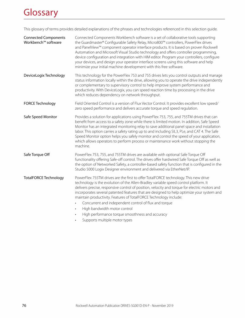
76 Rockwell Automation Publication DRIVES-SG001D-EN-P - November 2019
Glossary
This glossary of terms provides detailed explanations of the phrases and technologies referenced in this selection guide.
Connected Components Connected Components Workbench software is a set of collaborative tools supporting the Guardmaster® Configurable Safety Relay, Micro800™ controllers, PowerFlex drives and PanelView™ component operator interface products. It is based on proven Rockwell Automation and Microsoft Visual Studio technology and offers controller programming, device configuration and integration with HIM editor. Program your controllers, configure your devices, and design your operator interface screens using this software and help minimize your initial machine development with this free software.
DeviceLogix Technology This technology for the PowerFlex 753 and 755 drives lets you control outputs and manage status information locally within the drive, allowing you to operate the drive independently or complementary to supervisory control to help improve system performance and productivity. With DeviceLogix, you can speed reaction time by processing in the drive which reduces dependency on network throughput.
FORCE Technology Field Oriented Control is a version of Flux Vector Control. It provides excellent low speed/zero speed performance and delivers accurate torque and speed regulation.
Safe Speed Monitor Provides a solution for applications using PowerFlex 753, 755, and 755TM drives that can benefit from access to a safety zone while there is limited motion. In addition, Safe Speed Monitor has an integrated monitoring relay to save additional panel space and installation labor. This option carries a safety rating up to and including SIL3, PLe, and CAT 4. The Safe Speed Monitor option helps you safely monitor and control the speed of your application, which allows operators to perform process or maintenance work without stopping the machine.
Safe Torque Off PowerFlex 753, 755, and 755TM drives are available with optional Safe Torque Off functionality offering Safe-off control. The drives offer hardwired Safe Torque Off as well as the option of Networked Safety, a controller-based safety function that is configured in the Studio 5000 Logix Designer environment and delivered via EtherNet/IP.
TotalFORCE Technology PowerFlex 755TM drives are the first to offer TotalFORCE technology. This new drive technology is the evolution of the Allen-Bradley variable speed control platform. It delivers precise, responsive control of position, velocity and torque for electric motors and incorporates several patented features that are designed to help optimize your system and maintain productivity. Features of TotalFORCE Technology include:• Concurrent and independent control of flux and torque• High bandwidth motor control• High performance torque smoothness and accuracy• Supports multiple motor types
Workbench™ software


Publication DRIVES-SG001D-EN-P – November 2019 Copyright © 2019 Rockwell Automation, Inc. All Rights Reserved. Printed in USA. Supersedes Publication DRIVES-SG001C-EN-P – May 2017
Allen-Bradley, CENTERLINE, Connected Components Workbench, DeviceLogix, Encompass, Guardmaster, Installed Base Evaluation, Integrated Architecture, LISTEN. THINK. SOLVE., Micro800, PanelView, PowerFlex, Rockwell Automation, Rockwell Software, Studio 5000, Studio 5000 Logix Designer, and TotalFORCE are trademarks of Rockwell Automation, Inc. EtherNet/IP is a trademark of ODVA, Inc.Trademarks not belonging to Rockwell Automation are property of their respective companies.
Maximize Your Automation Investment
Rockwell Automation Services & SupportGlobal Support. Local Address. Peace of Mind.Providing the resources you need, when and where you need them, Rockwell Automation has an integrated, global network of ISO-certified repair centers, exchange hubs, field service professionals, IACET-recognized training centers, certified technical phone support centers and online tools.
www.rockwellautomation.com/go/services
Visit the Rockwell Automation Support Center at www.rockwellautomation.com/knowledgebase for technical information and assistance, plus:
• View technical/application notes • Subscribe for product/service email notifications
• Obtain software patches • Submit a Question, Live Chat, Support Forums and more
Visit Get Support Now at www.rockwellautomation.com/go/support to select your country and find your local support information.
MRO Demand Management
• Comprehensive asset management planning
• Reliability services
• Warranty tracking
• Quick access to global spare parts inventory
Lifecycle Extension & Migrations
• Installed Base Evaluation™ services
• Pinpoint obsolescence risk
• Tools and lifecycle support service agreements to mitigate production risk
Network & Security Services
• Control system lifecycle services
• Manage network convergence
• Security technology, policies and procedures services
Safety Services
• Safety assessments and remediation
• Safety design, integration and validation services
Meet Your Everyday Technical NeedsRemote Support & Monitoring
• Real-time product, system and application-level support
• Unlimited online resources and tools
• Live chat and support forums
• Secure equipment monitoring, alarming and diagnostics
Training Services
• Instructor-led and computer or web-based courses
• Virtual classroom
• Training assessments
• Workstations and job aids
OnSite Services
• Embedded engineering
• Preventive maintenance
• Migrations and conversions
• Start-up and commissioning
Repair Services
• Product remanufacturing
• Repair services on a full range of industrial automation brands and products
• Annual repair agreements