powerm ®®® 2000 s - nec corporation of america · sacramento, ca 95828-1037 ... powermate 2000...
TRANSCRIPT

When Space is at a Premium and Flexibility is Key
PPPPOWEROWEROWEROWERMMMMATEATEATEATE ®®®® 2000 S2000 S2000 S2000 SERIESERIESERIESERIES
SSSS E R V I C E A N D E R V I C E A N D E R V I C E A N D E R V I C E A N D RRRR E F E R E N C EE F E R E N C EE F E R E N C EE F E R E N C EMMMM A N U A LA N U A LA N U A LA N U A L

First Printing — September 1999
Copyright 1999NEC Computer Systems Division
6000 Florin-Perkins RoadSacramento, CA 95828-1037
All Rights Reserved
Proprietary Notice and Liability Disclaimer
The information disclosed in this document, including all designs and related materials, is thevaluable property of NEC Computer Systems Division, Packard Bell NEC, Inc. (hereinafter “NECCSD”) and/or its licensors. NEC CSD and/or its licensors, as appropriate, reserve all patent,copyright and other proprietary rights to this document, including all design, manufacturing,reproduction, use, and sales rights thereto, except to the extent said rights are expressly granted toothers.
The NEC CSD product(s) discussed in this document are warranted in accordance with the terms ofthe Warranty Statement accompanying each product. However, actual performance of each suchproduct is dependent upon factors such as system configuration, customer data, and operatorcontrol. Since implementation by customers of each product may vary, the suitability of specificproduct configurations and applications must be determined by the customer and is not warrantedby NEC CSD.
To allow for design and specification improvements, the information in this document is subject tochange at any time, without notice. Reproduction of this document or portions thereof without priorwritten approval of NEC CSD is prohibited.
As an ENERGY star partner, NEC Computer Systems Division (NEC CSD) has determined that this product meets theENERGY star guidelines for energy efficiency.
NEC and PowerMate are registered trademarks of NEC Corporation, used under license.
ENERGY STAR is a U.S. registered trademark.All other product, brand, or trade names used in this publication are the trademarks or registered trademarks of their
respective trademark owners.

Contents iii
ContentsPreface.................................................................................................................................. xiAbbreviations ..................................................................................................................... xiii
1 System OverviewConfiguration ..................................................................................................................... 1-2Features .............................................................................................................................. 1-4
Front Features ............................................................................................................... 1-4System Unit Front Features................................................................................. 1-5LCD Panel Front Features................................................................................... 1-5
Left Side Features ......................................................................................................... 1-6Right Side Features....................................................................................................... 1-7Rear Features ................................................................................................................ 1-8Inside Features .............................................................................................................. 1-9Security Features......................................................................................................... 1-10
Components ..................................................................................................................... 1-10System Board.............................................................................................................. 1-11LCD Panel .................................................................................................................. 1-11Diskette Drive ............................................................................................................. 1-11Hard Drive .................................................................................................................. 1-11CD-ROM Drive .......................................................................................................... 1-12AC Power Adapter and AC Power Cord .................................................................... 1-12Keyboard..................................................................................................................... 1-12Mouse ......................................................................................................................... 1-12AGP ............................................................................................................................ 1-13Speaker Set ................................................................................................................. 1-13Network Board............................................................................................................ 1-13PC Card Bay ............................................................................................................... 1-13
2 System ConfigurationInterrupt Requests .............................................................................................................. 2-2
System Interrupts .......................................................................................................... 2-2Parallel Port Interrupts .................................................................................................. 2-3Serial Port Interrupts..................................................................................................... 2-4
Jumper Settings .................................................................................................................. 2-4System Board Jumper Settings ..................................................................................... 2-4IBM Mobile Hard Drive Jumper Settings..................................................................... 2-5Hitachi Mobile Hard Drive Jumper Setting .................................................................. 2-6TEAC Mobile 24X CD-ROM Drive Jumper Settings .................................................. 2-6
BIOS Setup Utility ............................................................................................................. 2-6How to Start BIOS Setup.............................................................................................. 2-7How to Use Setup ......................................................................................................... 2-7Main Menu.................................................................................................................... 2-9Advanced Menu.......................................................................................................... 2-12Security Menu............................................................................................................. 2-15Power Menu................................................................................................................ 2-17Boot Menu .................................................................................................................. 2-18Exit Menu ................................................................................................................... 2-19
FLASH Utility.................................................................................................................. 2-20
iv Contents
NEC Application and Driver CD .....................................................................................2-20Launching the Application and Driver CD .................................................................2-21Installing Software ......................................................................................................2-21
NEC INFO Center ............................................................................................................2-22Installing the NEC INFO Center .................................................................................2-23Uninstalling the NEC INFO Center ............................................................................2-23
NEC OS Restore CD ........................................................................................................2-24Introducing OS Restore Options .................................................................................2-24Choosing a Restore Program.......................................................................................2-24Launching the NEC OS Restore CD ...........................................................................2-25Auto Rebuild and Restore ...........................................................................................2-26Custom Rebuild and Restore.......................................................................................2-27Fixing the Operating System.......................................................................................2-29
LANDesk Client Manager................................................................................................2-30PC Health Indicator.....................................................................................................2-31
Managing Workstations ..................................................................................... 2-31Selecting the PC Health Meter ........................................................................... 2-31Monitoring PC Health ........................................................................................ 2-32
Inventory .....................................................................................................................2-32DMI.............................................................................................................................2-33Monitoring Capabilities...............................................................................................2-33
Using the Chassis Intrusion Notification Feature............................................... 2-33LDCM Admin Function ..............................................................................................2-34
Cheyenne Backup.............................................................................................................2-34NEC ToolTelligent Suite..................................................................................................2-35
Installing ToolTelligent Utilities.................................................................................2-35NEC WebTelligent......................................................................................................2-36
NEC WebTelligent Features .............................................................................. 2-37NEC WebTelligent Requirements...................................................................... 2-38NEC WebTelligent Installation .......................................................................... 2-39
NEC SNMP Agent ......................................................................................................2-42Installing the NEC SNMP Agent ....................................................................... 2-42Configuring the NEC SNMP Agent for Windows 98 or Windows 2000........... 2-43Configuring the NEC SNMP Agent for Windows NT....................................... 2-44
NEC Configuration Change Notification ....................................................................2-45NEC Auto Backup Utility ...........................................................................................2-45
3 Disassembly and ReassemblyHard Drive Removal...........................................................................................................3-3SO-DIMM Module Removal .............................................................................................3-5Bottom Cover Removal......................................................................................................3-7CD-ROM Drive Removal...................................................................................................3-8Diskette Drive Removal .....................................................................................................3-9System Board and Support Plate Assembly Removal......................................................3-10Support Plate Removal .....................................................................................................3-12Network Board Assembly Removal .................................................................................3-13LAN Connector Board Removal ......................................................................................3-14PC Card Bay Removal......................................................................................................3-14CMOS Battery Removal...................................................................................................3-15CPU Fan Removal............................................................................................................3-16Processor and Heat Sink Removal....................................................................................3-17Hard Drive Bay and Drive Removal ................................................................................3-20LCD Panel Removal.........................................................................................................3-20

Contents v
4 System BoardConnectors, Jumpers, and Sockets ..................................................................................... 4-2
External Cable Connectors ........................................................................................... 4-2Internal Connectors, Sockets, and Jumpers .................................................................. 4-3System Board Jumpers.................................................................................................. 4-4
Clearing the Password......................................................................................... 4-4SO-DIMM Upgrade Sockets ........................................................................................ 4-5
Components ....................................................................................................................... 4-6Processor and Secondary Cache ................................................................................... 4-9System BIOS................................................................................................................. 4-9System Memory.......................................................................................................... 4-10PCI Local Bus............................................................................................................. 4-10PCI/IDE Port............................................................................................................... 4-11Parallel Interface ......................................................................................................... 4-11Serial Interface............................................................................................................ 4-12USB Interface ............................................................................................................. 4-12Accelerated Graphics Port .......................................................................................... 4-12Graphics Controller..................................................................................................... 4-13Integrated Audio ......................................................................................................... 4-13
5 Illustrated Parts BreakdownOrdering Parts .................................................................................................................... 5-2Field Replaceable Unit List................................................................................................ 5-2Illustrated Parts Breakdown ............................................................................................... 5-4
6 Preventive MaintenanceSystem Cleaning ................................................................................................................ 6-2Keyboard Cleaning ............................................................................................................ 6-2Mouse Cleaning ................................................................................................................. 6-3
7 TroubleshootingChecklist ............................................................................................................................ 7-2
System Problems........................................................................................................... 7-2Diskette Drive Problems............................................................................................... 7-3LCD Panel Problems .................................................................................................... 7-4Keyboard/Mouse Problems........................................................................................... 7-4CD-ROM Drive Problems ............................................................................................ 7-5Speaker Problems ......................................................................................................... 7-5
Diagnostics......................................................................................................................... 7-6
8 NEC CSD Information ServicesService Telephone Numbers .............................................................................................. 8-2Technical Support .............................................................................................................. 8-2
NEC CSD Website........................................................................................................ 8-2Email/Fax Technical Support Service .......................................................................... 8-3Technical Support Services .......................................................................................... 8-3
Product Information ........................................................................................................... 8-4NEC CSD FTP Site....................................................................................................... 8-4NEC CSD Bulletin Board System ................................................................................ 8-4
vi Contents
9 SpecificationsSystem Unit ........................................................................................................................9-3LCD Panel ..........................................................................................................................9-4Keyboard ............................................................................................................................9-4Mouse .................................................................................................................................9-5AC Power Adapter .............................................................................................................9-5System Board .....................................................................................................................9-6Network Board ...................................................................................................................9-6Diskette Drive.....................................................................................................................9-76.4-GB IBM Mobile Hard Drive ........................................................................................9-86.4-GB Hitachi Hard Drive ................................................................................................9-9TEAC 24X CD-ROM Drive.............................................................................................9-10PC Card Slots ...................................................................................................................9-11Speakers............................................................................................................................9-11Environmental and Safety ................................................................................................9-12Compliance.......................................................................................................................9-12
Glossary
Index
Regulatory Statements

Contents vii
List of FiguresPowerMate 2000 Series System Components .......................................................................................... 1-2PowerMate 2000 System Unit Front Features .......................................................................................... 1-4PowerMate 2000 LCD Panel Front Features ............................................................................................ 1-4Left Side Features ..................................................................................................................................... 1-6Right Side Features................................................................................................................................... 1-7System Unit Rear View ............................................................................................................................ 1-8Inside the System Unit.............................................................................................................................. 1-9Setup Main Menu ..................................................................................................................................... 2-7NEC INFO Center Opening Screen........................................................................................................ 2-23Welcome Screen ..................................................................................................................................... 2-25NEC WebTelligent ................................................................................................................................. 2-37WebTelligent Login Screen .................................................................................................................... 2-41NEC WebTelligent Control Screen ........................................................................................................ 2-41Removing the Hard Drive Panel ............................................................................................................... 3-3Removing the Hard Drive......................................................................................................................... 3-4Removing the SO-DIMM Module Panel .................................................................................................. 3-5Releasing the SO-DIMM Module............................................................................................................. 3-6Installing a SO-DIMM Module ................................................................................................................ 3-6Removing the Bottom Cover .................................................................................................................... 3-7Removing the CD-ROM Drive................................................................................................................. 3-8Removing the Diskette Drive ................................................................................................................... 3-9Removing the System Board and Support Plate Assembly .................................................................... 3-10Removing the Support Plate Mounting Screws ...................................................................................... 3-12Removing the Network Board ................................................................................................................ 3-13Removing the PC Card Bay.................................................................................................................... 3-14Removing the Battery ............................................................................................................................. 3-15Removing the CPU Fan .......................................................................................................................... 3-16Removing the Processor and Heat Sink.................................................................................................. 3-18Removing the LCD Panel ....................................................................................................................... 3-20Installing the LCD Panel......................................................................................................................... 3-21System Board External Cable Connector Locations................................................................................. 4-2System Board External Audio Connectors ............................................................................................... 4-3System Board Internal Connector, Socket, and Jumper Locations - Side 1.............................................. 4-3System Board Internal Connector and Socket Locations - Side 2 ............................................................ 4-4Removing a Typical Mouse Ball Cover.................................................................................................... 6-3
List of TablesPowerMate 2000 Series System Configuration ........................................................................................ 1-3System Components ............................................................................................................................... 1-10Interrupt Level Assignments..................................................................................................................... 2-3Parallel Port Interrupts.............................................................................................................................. 2-3Serial Port Interrupts................................................................................................................................. 2-4IBM Mobile Hard Drive Jumper Settings................................................................................................. 2-5Hitachi Mobile Hard Drive Jumper Settings............................................................................................. 2-6TEAC 24X CD-ROM Drive Jumper Settings........................................................................................... 2-6Setup Key Functions................................................................................................................................. 2-8Main Menu Items...................................................................................................................................... 2-9Advanced Menu...................................................................................................................................... 2-13Security Menu Items............................................................................................................................... 2-16Power Menu Settings.............................................................................................................................. 2-17Boot Menu Settings ................................................................................................................................ 2-18Exit Menu Items ..................................................................................................................................... 2-19PowerMate 2000 Series Disassembly Sequence....................................................................................... 3-2Supported SO-DIMMs.............................................................................................................................. 4-5Sample SO-DIMM Upgrade Paths ........................................................................................................... 4-6System Board Components....................................................................................................................... 4-8Parallel Port Addresses ........................................................................................................................... 4-11

viii Contents
Serial Port I/O Addresses........................................................................................................................ 4-12Ordering Parts ........................................................................................................................................... 5-2PowerMate 2000 Series System FRU List ................................................................................................ 5-2Problems and Solutions............................................................................................................................. 7-6NEC CSD Service and Support Telephone Numbers ............................................................................... 8-2System Specifications ............................................................................................................................... 9-2System Unit Specifications ....................................................................................................................... 9-3LCD Panel Specifications ......................................................................................................................... 9-4Keyboard Specifications ........................................................................................................................... 9-4Mouse Specifications ................................................................................................................................ 9-5AC Power Adapter Specifications ............................................................................................................ 9-5System Board Specifications..................................................................................................................... 9-6Network Board Specifications .................................................................................................................. 9-6Diskette Drive Specifications.................................................................................................................... 9-76.4-GB IBM Mobile Hard Drive Specifications ....................................................................................... 9-86.4-GB Hitachi Mobile Hard Drive Specifications ................................................................................... 9-9TEAC 24X CD-ROM Drive Specifications............................................................................................ 9-10PC Card Slot Specifications .................................................................................................................... 9-11Speaker Specification.............................................................................................................................. 9-11Environmental and Safety Specifications ............................................................................................... 9-12System Compliance................................................................................................................................. 9-12

Preface ix
PrefaceThis manual contains technical information for servicing and repairing the NECPowerMate® 2000 Series computers manufactured by NEC Computer SystemsDivision. The manual contains hardware and interface information for userswho need an overview of system design. The manual includes system setupinformation, disassembly procedures, and an illustrated parts list. The manual isprepared for NEC CSD trained customer engineers, service center personnel,and dealers.
The manual is organized as follows.
Section 1 — System Overview, provides an overview of system features andincludes brief descriptions of system components.
Section 2 — System Configuration, includes information on system IRQs,jumpers, and BIOS. The section also contains information on powermanagement features and system utilities, including the BIOS flash utility andNEC OS Restore CD.
Section 3 — Disasssembly and Reassembly, provides computer disassemblyand reassembly procedures. Each procedure is supported by disassemblyillustrations.
Section 4 — System Board, includes information on cable and board connectorlocations, jumper settings, and upgrade sockets. Also provided is information onboard components.
Section 5 — Illustrated Parts Breakdown, includes an exploded view diagram(illustrated parts breakdown) and a parts list for field-replaceable parts.
Section 6 — Preventive Maintenance, provides recommended maintenanceinformation for maintaining the system in top condition.
Section 7 — Troubleshooting, includes information for solving possiblecomputer problems and their solutions.
Section 8 — NEC CSD Information Services, lists telephone numbers forobtaining service. The section also includes information on NEC CSD technicalsupport, website, and bulletin board service.
Section 9 — Specifications, provides specifications for the major componentsin the system, including the LCD panel, system board, network board, diskettedrive, hard drive, and CD-ROM drive.
Appendix A — NEC PowerMate 2000 Series Release Notes, describesrecommended operating procedures not documented in other PowerMate 2000Series documentation.

Abbreviations xi
A ampere
AC alternating current
ACK acknowledge
AGP accelerated graphics port
ASIC application-specificintegrated circuit
AT advanced technology(IBM PC)
ATA AT attachment
ATAPI AT attachment packetinterface
ATM asynchronous transfer mode
BBS Bulletin Board System
BCD binary-coded decimal
BCU BIOS Customized Utility
BIOS basic input/output system
bit binary digit
BUU BIOS Upgrade Utility
bpi bits per inch
bps bits per second
C capacitance
C centigrade
Cache high-speed buffer storage
CAM constantly addressablememory
CAS column address strobe
CD-ROM compact disk-ROM
CH channel
clk clock
cm centimeter
CMOS complementary metal oxidesemiconductor
COM communication
CONT contrast
CPGA ceramic pin grid array
CPU central processing unit
DAC digital-to-analog converter
DACK DMA acknowledge
dB decibels
DC direct current
DCC direct cable connection
DCE data communicationsequipment
DDC Display Data Channel
DIMM Dual In-Line Memory Module
DIP dual in-line package
DMA direct memory access
DMAC DMA controller
DMI Desktop ManagementInterface
DOS disk operating system
DRAM dynamic RAM
DVD digital versatile disc
DVMT Dynamic Video MemoryTechnology
ECC error checking and correction
ECP extended capabilities port
EDO extended data output
EGA Enhanced Graphics Adapter
EISA enhanced ISA
email electronic mail
EMI electromagnetic interference
EPP enhanced parallel port
EPROM erasable and programmableROM
ESD electrostatic discharge
EVGA Enhanced Video GraphicsArray
F Fahrenheit
FAX facsimile transmission
FCC Federal CommunicationsCommission
FG frame ground
FM frequency modulation
FP fast page
FRU field-replaceable unit
Abbreviations

xii Abbreviations
FSB front side bus
ftp file transfer protocol
GB gigabyte
GND ground
HEX hexadecimal
HGA Hercules Graphics Adapter
Hz hertz
IC integrated circuit
ID identification
IDE intelligent device electronics
IDTR interrupt descriptor tableregister
in. inch
INTA interrupt acknowledge
I/O input/output
IPB illustrated parts breakdown
IPC integrated peripheralcontroller
ips inches per second
IR infrared
IrDA Infrared Data Association
IRR Interrupt Request register
ISA Industry StandardArchitecture
ISP internet service provider
IRQ interrupt request
K kilo (1024)
k kilo (1000)
KB kilobyte
kg kilogram
kHz kilohertz
lb pound
LAN local area network
LCD liquid crystal display
LED light-emitting diode
LDCM LANDesk Client Manager
LSB least-significant bit
LSI large-scale integration
M mega (million)
mA milliamps
max maximum
MB megabyte
MFM modified frequency modulation
MHz megahertz
MIDI musical instrument digitalinterface
mm millimeter
MMX multimedia extensions
modem modulator/demodulator
MOS metal-oxide semiconductor
MPEG Motion Picture Experts Group
ms millisecond
MSB most-significant bit
NC not connected
NIC networked information center
NMI Non-maskable Interrupt
ns nanosecond
OCR optical character recognition
OS operating system
PAL programmable array logic
PC personal computer
PCB printed circuit board
PCI Peripheral ComponentInterconnect
PDA personal digital assistant
PFP plastic flat package
PIO parallel input/output
pixel picture element
PLCC plastic leaded chip carrier
PLL phase lock loop
POST Power-On Self-Test
p-p peak-to-peak
PPI programmable peripheralinterface
PROM programmable ROM
PS/2 personal system/2
QFP quad flat pack
R read
RAM random-access memory
RAMDAC RAM digital-to-analogconverter

Abbreviations xiii
RAS row address strobe
RGB red green blue
RGBI red green blue intensity
rms root mean square
ROM read-only memory
rpm revolutions per minute
RTC real-time clock
R/W read/write
S slave
SCSI Small Computer SystemInterface
SDRAM synchronous dynamic randomaccess memory
S.E.C. single edge contact cartridge
SG signal ground
SGRAM synchronous graphics randomaccess memory
SIMM single inline memory module
S/N signal to noise ratio
SNMP simple network managementprotocol
SO-DIMM Small Outline Dual InlineMemory Module
SPM standard page mode
SRAM static random access memory
SRS Sound Retrieval System
SSI small scale integration
SVGA Super Video Graphics Array
SW switch
T&D test and diagnostics
TFT thin film transistor
TN twisted nematic
TSC Technical Support Center
TTL transistor/transistor logic
tpi tracks per inch
UART universal asynchronousreceiver/transmitter
UHF ultra high frequency
UL Underwriter’s Laboratories
UMA unified memory architecture
UPS uninterruptible power supply
URL uniform resource locator
USB universal serial bus
V volt
Vac volts, alternating current
VCR video cassette recorder
Vdc volts, direct current
VDT video display terminal
VESA video electronics standardsassociation
VFC VESA-compliant featureconnector
VGA Video Graphics Array
VHF very high frequency
VLSI very large scale integration
VRAM video RAM
W watt
WAN wide area network
WRAM Windows RAM
W write
www world wide web
XGA Extended Graphics Array
1System Overview
! Configuration
! Features
! Components

1-2 System Overview
This section provides an overview of the NEC PowerMate 2000 Series systemand includes descriptions of:
! system hardware
! system front, back, sides, bottom, and inside
! system security
! major system components.
The following figure shows the major components comprising the PowerMate2000 Series system.
PowerMate 2000 Series System Components
A – AC Power Cord D – System UnitB – AC Power Adapter E – MouseC – LCD Panel F – Keyboard
ConfigurationNEC PowerMate 2000 Series systems feature a liquid crystal display (LCD)panel, an Intel Celeron 433-MHz processor, two Small Outline Dual InlineMemory Module (SO-DIMM) sockets, synchronous dynamic random accessmemory (SDRAM), Dynamic Video Memory Technology (DVMT), and a plugand play input/output (I/O) controller.
The system also features two universal serial bus (USB) ports, a serial port, aparallel port, and a local area network (LAN) connector. Remote wakeup(“Wake-On LAN”), accelerated graphics port (AGP), and power managementare supported.

System Overview 1-3
The system ships with a 6.4-gigabyte (GB) intelligent device electronics (IDE)hard drive and a minimum of 64 megabytes (MB) of total system memory. Withthe DVMT feature, total system memory is dynamically shared between systemmemory and video memory. For example, with 64 MB of total system memory,56 MB is typically allocated for system memory and 8 MB allocated for videomemory, with actual memory use dependent on video usage. Total systemmemory is upgradeable up to 256 MB using 64-MB, 128-MB, 192-MB, and256-MB SO-DIMM modules.
The following table summarizes the PowerMate 2000 series systemconfiguration.
PowerMate 2000 Series System Configuration
Component Description
System Board NEC Proprietary Board G7CPYA
CPU Intel® Celeron™ 433-MHz, 100-MHz Front Side Bus (FSB)
CPU Mount Socket370
Cache 32-KB L1 cache and 128-KB L2 cache integrated on processor
AGP AGP integrated on system board
Chip Set Intel 810 with 82810 Graphics Memory Controller Hub, 82801AB I/O ControllerHub, and 82802 Firmware Hub
Audio Analog Devices AD1881 AC’97 SoundMAX® Codec chip integrated with Intel82801AB chip on system board
Total System Memory*(includes system andvideo memory)
64 MB (minimum) to 256 MB (maximum) of SDRAM in 2 SO-DIMM sockets
LCD Panel 15-inch, high resolution active matrix twisted nematic (TN) TFT Super VideoGraphics Array (SVGA) color display
Hard Drive Hitachi or IBM Mobile 6.4-GB IDE Ultra DMA/33
Diskette Drive Samsung Mobile 3 1/2-inch 1.44-MB (SFD-321B)
CD-ROM Drive TEAC or NEC Mobile ATAPI 24X
LAN Network Board Intel 82559 Chip, 10Base-T/100Base-TX with Wake-On LAN
PC Card Slots Two PCMCIA CardBus slots for Type II cards
Speakers Two Pioneer 1-watt speakers integrated in base of LCD panel
Keyboard Standard NEC PS/2-compatible keyboard
Mouse Standard PS/2-compatible mouse
Power AC Power Adapter with built-in power converter and detachable AC power cord:90 watt, 100 to 240 Volt, 50-60 Hz
* Component varies by system
1-4 System Overview
FeaturesThe system front, back, rear, bottom, and inside features are described in thefollowing paragraphs. Also included are descriptions of system securityfeatures.
Front Features
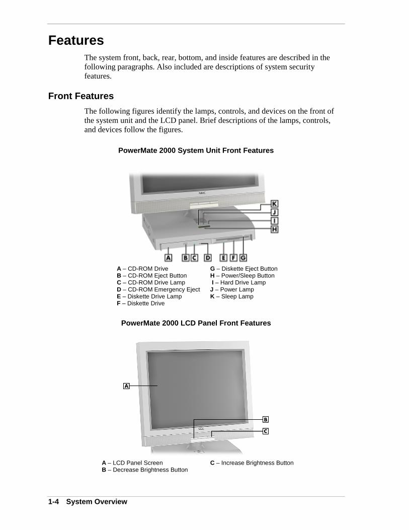
The following figures identify the lamps, controls, and devices on the front ofthe system unit and the LCD panel. Brief descriptions of the lamps, controls,and devices follow the figures.
PowerMate 2000 System Unit Front Features
A – CD-ROM Drive G – Diskette Eject ButtonB – CD-ROM Eject Button H – Power/Sleep ButtonC – CD-ROM Drive Lamp I – Hard Drive LampD – CD-ROM Emergency Eject J – Power LampE – Diskette Drive Lamp K – Sleep LampF – Diskette Drive
PowerMate 2000 LCD Panel Front Features
A – LCD Panel Screen C – Increase Brightness ButtonB – Decrease Brightness Button

System Overview 1-5
System Unit Front Features
The system unit has the following devices, controls, and lamps on the front ofthe system unit (see the above figure for device, control, and lamp locations).
! Power/Sleep button — press this button to turn power on. To turn off thesystem, press the button and hold in for four seconds or more beforereleasing.
Press (for no more than three seconds) and immediately release the powerbutton to suspend system operation and go into the power saving mode.
An amber sleep lamp indicates that the system is in a power saving mode.
Press any key or move the mouse to resume system operation.
! Power lamp — indicates if system power is on or off. A steady greenlamp indicates that power is on.
! Sleep lamp — indicates if system is in sleep mode. A steady amber lampindicates that the system is in sleep mode with full power reduction.
! Hard drive lamp — when lit, indicates that the hard drive is active and isreading or writing data.
! CD-ROM drive — load and start programs from a compact disc (CD) andto play audio CDs.
! Diskette drive — copy data files to and from a diskette or use as abootable drive for loading and starting programs from a diskette.
LCD Panel Front Features
The LCD panel has the following controls on the front of the system unit (seethe above figure for control locations).
! Decrease brightness level button — use this button to decrease displaybrightness.
! Increase brightness level button — use this button to increase displaybrightness.
The LCD panel can also be adjusted up or down and side-to-side for acomfortable viewing position.
Two 1-watt speakers are built into the base of the LCD panel.

1-6 System Overview
Left Side Features
The following figure identifies the controls and devices on the left side of thesystem unit. Brief descriptions of the controls and devices follow the figures.
Left Side Features
A – PC Card Slot 1 F – Microphone In JackB – Slot 1 Card Eject Button G – Line In JackC – Slot 2 Card Eject Button H – Headphone JackD – PC Card Slot 2 I – Volume ControlE – CPU Fan J – System Unit
The left side of the system unit has the following devices and controls (see theabove figure for device and control locations).
! PC Card Slots 1 and 2 — supports use of 16-bit cards and 32-bit Type IIPC cards using CardBus technology.
! CPU fan — cools the Celeron processor.
! Microphone in jack — used to connect a microphone for recording audioinformation in data files.
! Line in jack — used to connect a stereo audio device.
! Headphone jack — used to connect an optional headphone set. Pluggingin the headset disables the built-in speakers.
! Volume control — adjusts the volume of the two speakers built into theLCD panel or adjust the volume of an optional head set.

System Overview 1-7
Right Side Features
The following figure shows the location of the hard drive panel on the right sideof the system unit. The hard drive is under the panel. A brief description of thehard drive follows the figure.
Right Side Features
A – Hard Drive Panel (hard drive behind panel)
The system’s 6.4-GB IDE hard drive is behind the hard drive panel on the rightside of the system unit. The hard drive can be removed by removing the panel,unplugging the interface cable, and using a pull tab to pull the drive out of thehard drive bay.

1-8 System Overview
Rear Features
The rear of the system unit contains external connectors and a DC power socket.The following figure identifies the connectors on the back of the system. Briefdescriptions of each connector follow the figure.
System Unit Rear View
A – PS/2 Mouse Port F – VGA ConnectorB – Security Lock Slot G – LAN ConnectorC – PS/2 Keyboard Port H – USB ConnectorsD – Printer Port I – DC Power ConnectorE – Serial Port
The system unit has the following external connectors.
! PS/2 mouse port — Attach a mouse (PS/2-compatible) with a 6-pin miniDIN connector to this port.
! Security lock slot — Attach a Kensington® Security Standard connector orother locking device to this slot.
! PS/2 keyboard port — Attach a keyboard (PS/2®-compatible, 101-key or102-key) with a 6-pin mini DIN connector to this port.
! Printer port — Attach a parallel printer with a 25-pin connector to thisport.
! Serial port — Allows the connection of a serial device with a 9-pinconnector. Devices include a pointing device, serial printer, or modem.
! VGA monitor connector — Attach a video graphics array (VGA)-compatible monitor (NEC MultiSync® monitor or other VGA-compatiblemonitor) with a 15-pin connector to this connector.
! LAN connector — Use this connector to attach a network cable to thesystem’s 100Base-TX/10Base-T network board.

System Overview 1-9
! USB connectors — Attach up to 127 USB devices to these connectors,including printers, monitors, modems, mouse, game pads/joysticks, andspeakers.
! DC power connector — Plug the AC power adapter into this connectorand the AC power cable into the adapter and an AC power outlet tosupply DC power to the system.
Inside Features
The following figure shows the interior of the system unit, as viewed from thebottom of the system unit with the bottom cover off. Not visible are the Celeronprocessor, network board, CMOS battery, and hard drive; all of which are underthe system board. A list of features follow the figure.
Inside the System Unit
A – Diskette Drive D – SO-DIMM Socket 0B – SO-DIMM Socket 1 E – System BoardC – Clear Password Jumper 7F4 F – CD-ROM Drive
The inside of the system has the following features:
! system board with connectors for the SO-DIMM memory, hard drive,diskette drive, CD-ROM drive, and network board; sockets for theCeleron processor and CMOS battery
! memory module(s)
! diskette drive
! hard drive
! CD-ROM drive
! network board
! PC card slots.
For more information on the above features, see “Components” in this section.

1-10 System Overview
Security Features
The system has hardware, software, and mechanical security features that offerprotection against unauthorized access to the system and data. The followingsecurity features are available:
! Password Security
The BIOS Setup utility includes a feature that allows a user to set either auser or supervisor password, or both.
The user password controls booting of the system and controls access tothe Setup utility and the keyboard. User access to the BIOS Setup utilityis limited when a supervisor password is set. The supervisor passwordallows full access to the system and the BIOS.
! Windows Network Security Features
The Windows Network Security feature is available through theWindows operating system. Check the Windows documentation fordetails.
! Security Lock Slot
The security lock slot accepts a Kensington Security Standard connectoror other locking device to physically protect the system unit fromintrusion.
ComponentsThe major system components are listed in the following table, along with thepage number where each component is briefly described.
System Components
Component Go to Page
System Board 1-11
LCD Panel 1-11
Diskette Drive 1-11
Hard Drive 1-11
CD-ROM Drive 1-12
AC Power Adapter 1-12
Keyboard 1-12
Mouse 1-12
AGP 1-13
Speaker Set 1-13
Network Board 1-13
PC Card Bay 1-13

System Overview 1-11
System Board
The system board contains the Celeron processor in a Slot370 connector, systemSO-DIMM memory in one or two memory sockets, and the Intel 810 chip set.The chip set contains the 82810 Graphics Memory Controller Hub, 82801 I/OController Hub, and 82802 Firmware Hub. Integrated on the system board is theAGP controller and the audio-Codec 97 audio controller.
Internal connectors on the system board include two SO-DIMM sockets,processor Slot370 connector, network board connector, hard disk connector,diskette connector, and CD-ROM connector.
External connectors on the system board include a serial connector, a parallelconnector, two USB ports, keyboard port, mouse port, local area network (LAN)connector, and external audio connectors.
The system board supports the standard 1.44-MB diskette drive and the standardIDE hard drive and CD-ROM drive.
For further information on the system board, see Section 4, “System Board.”
LCD Panel
The LCD panel uses a 15-inch, twisted nematic Thin Film Transistor (TFT)Super Video Graphics Array (SVGA) color screen. The screen has a brightnessof 200 candlepower, a maximum resolution of 1024 x 768 pixels, and supportsup to 16.8 million colors (True Color).
The LCD panel screen automatically turns on when you press the system powerbutton. An eight-level increase brightness button and decrease brightness buttonon the panel allows the user to increase or decrease the brightness of the display.The default for each button is mid-level brightness.
The LCD panel can be adjusted up or down and side-to-side for a comfortableviewing position. Two 1-watt speakers are built into the base of the LCD panel.
Diskette Drive
A single diskette drive is supported in the system. The installed 1.44-MB3 1/2-inch mobile diskette drive is connected by a single signal and powerribbon cable connected to the system board. There are no switches or jumpers toset and the diskette drive is terminated.
Diskette drive specifications are given in Section 9, “Specifications.”
Hard Drive
All systems ship with a 6.4-MB 3 1/2-inch mobile IDE hard drive installed onthe right side of the system unit. The installed mobile hard drive is connected bya single signal and power ribbon cable connected to the system board.

1-12 System Overview
Hard drive jumper settings are given in Section 2, “System Configuration.”Connector locations for the IDE hard drive connector on the system board aregiven in Section 4, “System Board.” Hard drive specifications are given inSection 9, “Specifications.”
CD-ROM Drive
All systems come with a 24X CD-ROM drive. The drive features up to24-speed technology, affording faster data transfer and smoother animation andvideo. The drive is compatible with Kodak Multisession Photo CDs™, CD-I,FMV, and CD Plus, as well as standard CDs. The CD-ROM drive can also playaudio CDs (for systems with sound capabilities).
The CD-ROM drive comes with an Enhanced IDE (EIDE) interface. The drive’ssingle signal and power ribbon cable directly connects to the system board.
CD-ROM jumper settings are included in Section 2, “System Configuration.”Specifications for the CD-ROM drive are given in Section 9, “SystemSpecifications.”
AC Power Adapter and AC Power Cord
System DC power comes from the AC power adapter. A converter built into theAC power adapter converts 110 to 230 Vac power to the DC power necessaryfor operating the system. The AC power adapter provides 90-watts of power forsystem use.
The AC power cord plugs into the AC power adapter and a 115 Vac or 220 Vacpower source.
The DC power connector locations on the system board are given in Section 4,“System Board.” Power supply specifications are given in Section 9,“Specifications.”
Keyboard
The PS/2-compatible ergodynamic keyboard is standard equipment for thesystem. The keyboard provides a numeric keypad, separate cursor control keys,12 function keys, and is capable of up to 48 functions. Key status lamps on thekeyboard include Num (Numeric) Lock, Caps (Capital) Lock, and Scroll Lock.
The keyboard’s six-pin connector plugs into the back of the system. Keyboardspecifications are given in Section 9, “Specifications.”
Mouse
The system ships with a standard PS/2-compatible mouse. The mouse has twobuttons and a cursor control wheel. The mouse has a self-cleaning mechanismthat prevents a buildup of dust or lint around the mouse ball and trackingmechanism.

System Overview 1-13
The six-pin mouse cable connector plugs into the back of the system. Mousespecifications are given in Section 9, “Specifications.”
AGP
All systems come with the graphics accelerator (AGP) integrated on the systemboard. The AGP provides an integrated, advanced MPEG (Motion PictureExperts Group), 3D and 2D graphics and video accelerator for exceptionalgraphics and superior quality full-screen, full-motion video.
Included on the system board is a standard VGA output connector forconnecting a VGA-compatible monitor to the AGP component.
Graphics modes are given in Section 2, “System Configuration.” Graphics boardspecifications are given in Section 9, “Specifications.”
Speaker Set
All systems come with two 1-watt stereo speakers integrated in the base of theLCD panel. Volume is adjusted by a volume control on the left side of thesystem unit. Volume can also be controlled by the Windows sound software.
Speaker specifications are given in Section 9, “Specifications.”
Network Board
All systems come with a 10/100 network board installed on the system board.Included on the system board is a LAN connector for connecting to a local areanetwork and the system’s network board.
Specifications for the network board are given in Section 9, “Specifications.”
PC Card Bay
All systems come with two PC card slots in the PC card bay. The two PC cardslots support two Type II cards using CardBus technology. PC cards can providethe system with memory, storage, fax/modem capabilities, or a serial portinterface.
PC slot connector locations are given in Section 4, “System Board.” PC slotspecifications are given in Section 9, “Specifications.”
2System Configuration
! Interrupt Requests
! Jumper Settings
! BIOS Setup Utility
! Flash Utility
! NEC Application and Driver CD
! NEC INFO Center
! NEC OS Restore CD
! LANDesk Client Manager
! Cheyenne Backup
! NEC ToolTelligent Suite

2-2 System Configuration
This section provides information for configuring the system. The sectionincludes:
! system interrupt request (IRQ) assignments
! system jumper settings
! procedures for using the BIOS Setup utility to configure the system
! descriptions and procedures for using the following utilities andapplications
Flash Utility
NEC Application and Driver CD
NEC INFO Center
NEC OS Restore CD
LANDesk Client Manager
Cheyenne Backup
NEC ToolTelligent Suite.
Interrupt RequestsThe following paragraphs list the system interrupts (IRQs), parallel addressesand interrupts, and serial addresses and interrupts.
System Interrupts
The system has 16 IRQs (IRQ 0 through 15) assigned to different devices (forexample, printer, keyboard, mouse). Initial IRQ settings are assigned at thefactory, with settings dependent on the installed device(s). Several IRQs areunassigned. See “BIOS Setup” utility in this section for information on using theutility to assign or change the interrupts.
The following table lists the IRQ settings. Settings 0 through 15 are in order ofdecreasing priority.

System Configuration 2-3
Interrupt Level Assignments
Interrupt Priority Interrupt Device
IRQ00 System Timer
IRQ01 Keyboard
IRQ02 Programmable Interrupt Controller
IRQ03 User Available
IRQ04 Communications Port
IRQ05 IRQ Holder for PCI Steering/Digital Audio/SMBusController/USB Universal Host Controller/CardBusController
IRQ06 Diskette Drive Controller
IRQ07 Parallel Port 1
IRQ08 Real-Time clock
IRQ09 User Available
IRQ10 IRQ Holder for PCI Steering/Network board/CardBusController/Graphics Driver
IRQ11 User Available
IRQ12 Wheel Mouse
IRQ13 Numeric Data Processor
IRQ14 Primary IDE Controller/Bus Master IDE Controller
IRQ15 Secondary IDE Controller/Bus Master IDE Controller
Parallel Port Interrupts
The parallel port I/O interrupts are given in the following table.
Parallel Port Interrupts
Port Interrupt
LPT1 IRQ07
LPT2 IRQ07
LPT3 IRQ07

2-4 System Configuration
Serial Port Interrupts
The interrupts for the communications serial port are given in the followingtable.
Serial Port Interrupts
Port Interrupt
COM1 IRQ04
COM3 IRQ04
COM2 IRQ04
COM4 IRQ04
Jumper SettingsJumpers on the boards and devices in the system are used to set the systemconfiguration. Boards and devices using jumpers include:
! system board
! hard drive
! CD-ROM drive.
The following paragraphs list the jumpers and their factory settings.
System Board Jumper Settings
The system board has three jumper blocks:
! clear password jumper block 7F4
! factory jumper block 2F19
! factory jumper block HE5.
Jumper block 7F4 is on the SO-DIMM side of the system board. Jumper blocks2F19 and HE5 are on the processor side of the board. Each jumper block isbriefly described in the following paragraphs.
Procedures for setting the jumpers are included in Section 4. Specifications forthe system board are included in Section 9.

System Configuration 2-5
Jumpers are set correctly at the factory for the systemconfiguration. Only change the appropriate jumper settings.Otherwise, keep the jumpers at their factory settings.
Jumper block 7F4 is a two-pin jumper block for clearing the system password ifthe password is forgotten. The factory setting for 7F4 is pins 1 and 2 jumpered.To clear the password, the system must be powered down, the jumper removedand reinstalled, and the system powered up.
Jumper block 2F19 is a three-pin jumper block for factory use. The factorysetting for 2F19 is pins 1 and 2 jumpered. This setting should not be changed.
Jumper block HE5 is a three-pin block for factory use. The factory setting forHE5 is pins 1 and 2 jumpered. This setting should not be changed.
IBM Mobile Hard Drive Jumper Settings
For systems with the IBM 6.4-MB IDE mobile hard drive, the factory settingsfor the jumper on the interface connector of the drive are shown in the followingtable. The factory setting is for a single drive installed on the IDE primarychannel. The 4-pin jumper block is located at the right end of the interfaceconnector on the drive (when looking at the rear of the drive).
Specifications for the hard drive are included in Section 9.
IBM Mobile Hard Drive Jumper Settings
Function Jumper Pins Description
Master Device No Jumper Sets hard drive as master device in single drive system.Factory setting: no jumper.
Slave Device Jumperposition 1
Sets hard drive as slave (the two right most pinsjumpered).
Cable Select(CSEL)
Jumperposition 3
Not used.

2-6 System Configuration
Hitachi Mobile Hard Drive Jumper Setting
For systems with the Hitachi 6.4-MB IDE mobile hard drive, the factory settingsfor the jumper on the interface connector are shown in the following table. Thefactory setting is for a single drive installed on the primary IDE channel. The4-pin jumper block is located at the right end of the interface connector on thedrive (when looking at the rear of the drive).
Specifications for the hard drive are included in Section 9.
Hitachi Mobile Hard Drive Jumper Settings
Function Jumper Pins Description
Master Device Pins A, B, C,D notjumpered
Sets hard drive as master device in single drive system.Factory setting: no jumper.
Slave Device Pins A and Bjumpered
Sets hard drive as slave.
Cable Select(CSEL)
Pins B and Djumpered
Not used.
TEAC Mobile 24X CD-ROM Drive Jumper Settings
Jumper settings for the TEAC 24X CD-ROM drive are shown in the followingtable. The factory setting is for a single drive installed on the IDE secondarychannel. Specifications for the CD-ROM drive are included in Section 9.
TEAC 24X CD-ROM Drive Jumper Settings
Jumper Jumper Pin Settings
Master Select (MA) Enabled. Factory setting: jumper over right-most pinsof 6-pin jumper block on back of drive, next tointerface cable connector.
Slave Present (SL) Disabled.
Cable Select (CS) Not used.
BIOS Setup UtilityThe Phoenix® Technologies Ltd. BIOS Setup utility program is used toconfigure the main components of the system.
The system ships from the factory with the correct system parameters for theconfiguration. Unless optional hardware is added, it’s not necessary to run theBIOS Setup utility to operate the system. However, the Setup utility should berun to set features that customize the system, such as security features.

System Configuration 2-7
NEC CSD recommends that the current BIOS Setup parameters be printed outor written down and the information stored in a safe place. This lets you restorethe system to the current parameters if replacing the CMOS battery (see Section3, “Disassembly and Reassembly” for battery replacement procedures).
How to Start BIOS Setup
Start the BIOS Setup utility as follows.
1. Turn on or reboot the system.
2. Press F2 at the NEC startup screen (F2 appears at the bottom of the screen).
You have about five seconds to press F2 before the system boot continues.
Setup’s Main Menu appears similar to the following screen.
Note: The following screen is a typical system screen.The actual settings on the Main Menu depend upon thehardware installed in the system.
Setup Main Menu
How to Use Setup
The Setup utility has a Main Menu window and six top-level menus withsubmenus. The menu bar at the top of the Main Menu window lists thefollowing top-level menus.
! Main Use the Main menu for basic system configuration. For example,select Main to set the system time and date, set diskette and hard diskparameters, or check memory parameters.
2-8 System Configuration
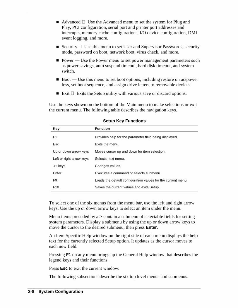
! Advanced Use the Advanced menu to set the system for Plug andPlay, PCI configuration, serial port and printer port addresses andinterrupts, memory cache configurations, I/O device configuration, DMIevent logging, and more.
! Security Use this menu to set User and Supervisor Passwords, securitymode, password on boot, network boot, virus check, and more.
! Power — Use the Power menu to set power management parameters suchas power savings, auto suspend timeout, hard disk timeout, and systemswitch.
! Boot — Use this menu to set boot options, including restore on ac/powerloss, set boot sequence, and assign drive letters to removable devices.
! Exit Exits the Setup utility with various save or discard options.
Use the keys shown on the bottom of the Main menu to make selections or exitthe current menu. The following table describes the navigation keys.
Setup Key Functions
Key Function
F1 Provides help for the parameter field being displayed.
Esc Exits the menu.
Up or down arrow keys Moves cursor up and down for item selection.
Left or right arrow keys Selects next menu.
-/+ keys Changes values.
Enter Executes a command or selects submenu.
F9 Loads the default configuration values for the current menu.
F10 Saves the current values and exits Setup.
To select one of the six menus from the menu bar, use the left and right arrowkeys. Use the up or down arrow keys to select an item under the menu.
Menu items preceded by a > contain a submenu of selectable fields for settingsystem parameters. Display a submenu by using the up or down arrow keys tomove the cursor to the desired submenu, then press Enter.
An Item Specific Help window on the right side of each menu displays the helptext for the currently selected Setup option. It updates as the cursor moves toeach new field.
Pressing F1 on any menu brings up the General Help window that describes thelegend keys and their functions.
Press Esc to exit the current window.
The following subsections describe the six top level menus and submenus.

System Configuration 2-9
Main Menu
Choose the Main menu by selecting Main in the legend bar on the Main menuscreen. Other Main menu options are available by selecting submenus.
Use the arrow keys to select one of the Main menu options and press Enter toselect a submenu. Items with grayed-out text are not available. Explanations ofeach Main menu item are given in the following table.
Setting items on this menu to incorrect values can cause thesystem to malfunction.
Main Menu Items
Menu Item Settings (default is bold)
System Time Set system time in this field. Press Tab or Enter to movebetween hour, minute, and second fields.
Example: 09:30:00
System Date Set system date in this field. Press Tab or Enter to movebetween month, date, and year fields.
Example:07/09/1999
Language English, Japanese
Selects the display language for the BIOS.
Legacy Diskette A Disabled360 KB 5 1/4"1.2 MB 5 1/4"720 KB 3 1/2"1.44/1.25 MB 3 1/2"2.88 MB 3 1/2"
Selects the diskette drive type.

2-10 System Configuration
Main Menu Items
Menu Item Settings (default is bold)
Primary IDE MasterPrimary IDE SlaveSecondary IDE MasterSecondary IDE Slave
6495 MBNoneCD-ROMNone
Note: The following setting information applies to the primaryand secondary master and slave devices.
Each device menu item displays the hard drive or CD-ROMidentifier if a device is installed.
If you install a hard drive that does not feature auto IDE typedetection or your IDE hard drive was formatted on anothersystem with parameters different from those reported by thedrive, enter a parameter for each of the fields in the devicesubmenu.
Bring up a device submenu by pressing Enter. The submenusinclude Type, CHS Format, and LBA Format. Each submenuand its fields are described next.
Type Auto, None, CD-ROM, IDE Removable, ATAPI Removable,Other ATAPI, or User
When set to Auto, the values for Cylinders, Heads, Sectors,and Maximum Capacity are displayed but are read only.
When set to Auto, the BIOS detects what the drive is capableof, not the translation mechanism that was used to format thedrive. If a drive is run in a mode other than the mode in whichit was partitioned and formatted, unpredictable results mayoccur, including data loss.
When set to None, informs the system to ignore this drive.
When set to CD-ROM, IDE Removable, ATAPI Removable, orOther ATAPI, allows the manual entry of all fields describednext.
When set to User, allows the manual entry of all fieldsdescribed next.
CHS Format (label fieldonly)
Cylinders When Type is Auto, value in the Cylinders field is auto-detected and field is read only.
Heads When Type is Auto, value in Heads field is auto-detected andfield is read only.
Sectors When Type is Auto, value in Sectors field is auto-detected andfield is read only.
Maximum Capacity xxxx MB

System Configuration 2-11
Main Menu Items
Menu Item Settings (default is bold)
LBA Format (label fieldonly)
Total Sectors xxxxxxxx total sectors
Maximum Capacity xxxx MB
Multi-Sector Transfers Disabled, 2, 4, 8, 16 sectors
Determines the number of sectors per block for multi-sectortransfers.
When Type is Auto, value in Multi-Sector Transfers field isauto-detected and field is read only.
LBA Mode Control Enabled, Disabled
When Enabled is selected, it causes logical block addressingto be used in place of cylinders, heads, and sectors.
When Type is set to Auto, the value in the LBA Mode field isauto-detected and the field is read only.
32-Bit I/O Disabled, Enabled
When Enabled, allows 32 bit data transfers.
Transfer Mode Standard, Fast PIO1, Fast PIO2, Fast PIO3, Fast PIO4, FastPIO3/DMA1, Fast PIO4/DMA2
Selects the method for moving data to and from the drive.
When Type is set to Auto, the value in the field is auto-detected and the field is read only.
Ultra DMA Mode Disabled, Mode 0, Mode 1, Mode 2, Mode 3, Mode 4
Selects the Ultra DMA Mode for moving data to and from thedrive. Autotype the drive to select the optimum transfer mode.
When Type is set to Auto, the value in the field is auto-detected and the field is read only.
Keyboard Features Press Enter to check or change keyboard parameters.
Numlock Auto, On, Off
Selects the power-on state for Num Lock.
Key Click Disabled, Enabled
Enables or disables key click.
Keyboard auto-repeat rate
30/sec, 26.7/sec, 21.8/sec, 18.5/sec, 13.3/sec, 10/sec, 6/sec,2/sec
Selects key repeat rate.
Keyboard auto-repeat delay
1/4 sec, 1/2 sec, 3/4 sec, 1 sec
Selects delay before key repeat.

2-12 System Configuration
Main Menu Items
Menu Item Settings (default is bold)
Legacy USB Support Disabled, Enabled
Disables or enables legacy USB support.
Boot-Time DiagnosticsScreen
Disabled, Enabled
Selecting Enabled displays the diagnostic screen during boot.
System Memory Displays amount of conventional memory detected duringboot.
This field is read-only and cannot be changed from BIOSSetup.
Example: 640 KB
Extended Memory Displays amount of extended memory detected during boot.
This field is read-only and cannot be changed from BIOSSetup.
Example: 63488 KB
BIOS Revision Displays the BIOS revision number.
This field is read-only and cannot be changed from the BIOSSetup.
Example: 130A0900
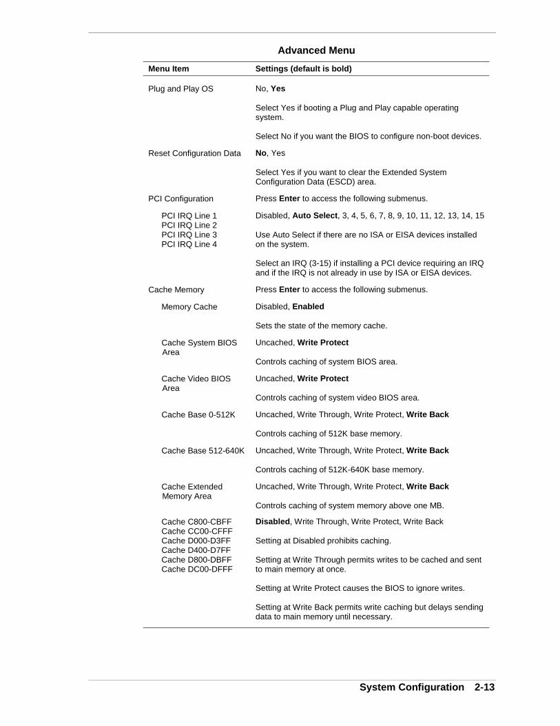
Advanced Menu
Choose the Advanced menu by selecting Advanced in the legend bar on theMain menu screen. Other Advanced menu options are available by selectingsubmenus.
Use the arrow keys to select one of the Advanced menu options and press Enterto select a submenu. Items with grayed-out text are not available. Explanationsof each Advanced menu item are in the following table.
Setting items on this menu to incorrect values can causeyour system to malfunction.
System Configuration 2-13
Advanced Menu
Menu Item Settings (default is bold)
Plug and Play OS No, Yes
Select Yes if booting a Plug and Play capable operatingsystem.
Select No if you want the BIOS to configure non-boot devices.
Reset Configuration Data No, Yes
Select Yes if you want to clear the Extended SystemConfiguration Data (ESCD) area.
PCI Configuration Press Enter to access the following submenus.
PCI IRQ Line 1PCI IRQ Line 2PCI IRQ Line 3PCI IRQ Line 4
Disabled, Auto Select, 3, 4, 5, 6, 7, 8, 9, 10, 11, 12, 13, 14, 15
Use Auto Select if there are no ISA or EISA devices installedon the system.
Select an IRQ (3-15) if installing a PCI device requiring an IRQand if the IRQ is not already in use by ISA or EISA devices.
Cache Memory Press Enter to access the following submenus.
Memory Cache Disabled, Enabled
Sets the state of the memory cache.
Cache System BIOS Area
Uncached, Write Protect
Controls caching of system BIOS area.
Cache Video BIOS Area
Uncached, Write Protect
Controls caching of system video BIOS area.
Cache Base 0-512K Uncached, Write Through, Write Protect, Write Back
Controls caching of 512K base memory.
Cache Base 512-640K Uncached, Write Through, Write Protect, Write Back
Controls caching of 512K-640K base memory.
Cache Extended Memory Area
Uncached, Write Through, Write Protect, Write Back
Controls caching of system memory above one MB.
Cache C800-CBFFCache CC00-CFFFCache D000-D3FFCache D400-D7FFCache D800-DBFFCache DC00-DFFF
Disabled, Write Through, Write Protect, Write Back
Setting at Disabled prohibits caching.
Setting at Write Through permits writes to be cached and sentto main memory at once.
Setting at Write Protect causes the BIOS to ignore writes.
Setting at Write Back permits write caching but delays sendingdata to main memory until necessary.

2-14 System Configuration
Advanced Menu
Menu Item Settings (default is bold)
I/O Device Configuration Press Enter to access the following submenus.
Serial Port A Disabled, Enabled, Auto
Setting at Enabled allows the user to configure the port.
Setting at Auto enables the BIOS or operating system toconfigure the port.
Base I/O Address
3F8, 2F8, 3E8, 2E8
Selects the base I/O address for serial port A.
Interrupt IRQ3, IRQ4
Selects the IRQ for serial port A.
Parallel Port Disabled, Enabled, Auto
Setting at Enabled allows the user to configure the port.
Setting at Auto enables the BIOS or operating system toconfigure the port.
Mode Output Only, Bi-directional, EPP, ECP
Selects parallel port mode.
Base I/O Address
378, 278, 3BC
Selects the base I/O address for the LPT port.
Interrupt IRQ5, IRQ7
Selects the IRQ for the LPT port.
Floppy Disk Controller Disabled, Enabled, Auto
Setting at Enabled allows the user to configure the controller.
Setting at Auto enables the BIOS or operating system toconfigure the controller.
Base I/O Address
Primary, Secondary
Sets the base I/O address for the controller.
Large Disk Access Mode Other, DOS
Select DOS if using DOS operating system.
Select Other if using another operating system such as UNIXor Novell NetWare.
Local Bus IDE Adapter Disabled, Primary, Secondary, Both
Enables the integrated local bus IDE adapter.

System Configuration 2-15
Advanced Menu
Menu Item Settings (default is bold)
Quick Boot Mode Disabled, Enabled
When Enabled, the BIOS does not test system memory above1 MB or wait for ready signals, allowing a quick boot.
Sound Enabled, Disabled
Select Disabled to turn off onboard sound.
PCMCIA Power 3.3 V, 5 V
Selects voltage for PC cards.
DMI Event Logging Press Enter to access the following submenus.
Event Log Capacity Status only, press Enter to view.
Event Log Validity Status only, press Enter to view.
View DMI Event Log Status only, press Enter to view.
Clear All DMI Event Logs
No, Yes
Selecting No prevents clearing out the DIMM event logs.
Event Logging Enabled, Disabled
Selecting Enabled permits logging of DMI events.
Mark DMI Events As Read
Press Enter. Select Yes or No to “Mark all Events as read?”
LANDesk ® Service Disabled, Enabled
Select Enabled to enable the onboard LANDesk.
Preboot Management Disabled, Enabled
Select Enabled to enable the Preboot Management function.
Security Menu
Choose the Security menu by selecting Security in the legend bar on the Mainmenu screen. Other Security menu options are available by selecting submenus.
Use the arrow keys to select one of the Security menu options and press Enterto select a submenu. Items with grayed-out text are not available. Explanationsof each Security menu item are in the following table.
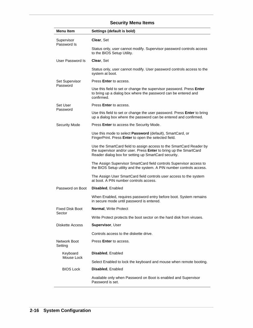
2-16 System Configuration
Security Menu Items
Menu Item Settings (default is bold)
SupervisorPassword Is
Clear, Set
Status only, user cannot modify. Supervisor password controls accessto the BIOS Setup Utility.
User Password Is Clear, Set
Status only, user cannot modify. User password controls access to thesystem at boot.
Set SupervisorPassword
Press Enter to access.
Use this field to set or change the supervisor password. Press Enterto bring up a dialog box where the password can be entered andconfirmed.
Set UserPassword
Press Enter to access.
Use this field to set or change the user password. Press Enter to bringup a dialog box where the password can be entered and confirmed.
Security Mode Press Enter to access the Security Mode.
Use this mode to select Password (default), SmartCard, orFingerPrint. Press Enter to open the selected field.
Use the SmartCard field to assign access to the SmartCard Reader bythe supervisor and/or user. Press Enter to bring up the SmartCardReader dialog box for setting up SmartCard security.
The Assign Supervisor SmartCard field controls Supervisor access tothe BIOS Setup utility and the system. A PIN number controls access.
The Assign User SmartCard field controls user access to the systemat boot. A PIN number controls access.
Password on Boot Disabled, Enabled
When Enabled, requires password entry before boot. System remainsin secure mode until password is entered.
Fixed Disk BootSector
Normal, Write Protect
Write Protect protects the boot sector on the hard disk from viruses.
Diskette Access Supervisor, User
Controls access to the diskette drive.
Network BootSetting
Press Enter to access.
Keyboard Mouse Lock
Disabled, Enabled
Select Enabled to lock the keyboard and mouse when remote booting.
BIOS Lock Disabled, Enabled
Available only when Password on Boot is enabled and SupervisorPassword is set.

System Configuration 2-17
Security Menu Items
Menu Item Settings (default is bold)
Virus CheckReminder
Disabled, Daily, Weekly, Monthly
Displays reminder message at bootup. Message is daily, everyMonday, or first of every month.
System BackupReminder
Disabled, Daily, Weekly, Monthly
Displays reminder message at bootup. Message is daily, everyMonday, or first of every month.
Power Menu
Choose the Power menu by selecting Power in the legend bar on the Main menuscreen. Other Power menu options are available by selecting submenus.
Use the arrow keys to select one of the Power menu options and press Enter toselect a submenu. Items with grayed-out text are not available. Explanations ofeach Power menu item are in the following table.
Note: Power management is only supported in systemsrunning Windows 98 and Windows 2000.
Power Menu Settings
Menu Item Settings (default is bold)
Power Savings Disabled, Customized, Maximum Power Savings, MaximumPerformance
Disabled setting turns off Power Management.
Maximum Power Savings setting conserves the greatest amount ofpower.
Maximum Performance setting conserves power but allows bestsystem performance.
Customized setting allows the user to modify the Auto SuspendTimeout and Hard Disk Timeout fields.
Auto Suspend Timeout
Off, 5, 10, 15, 20, 30, 40, 60 minutes
Specifies the amount of time the system is in standby before enteringthe sleep mode.
Hard Disk Timeout
Disabled10, 15, 30, 45 seconds1, 2, 4, 6, 8, 10, 15 minutes
Specifies the amount of time the hard drive needs to be inactive beforeit is turned off.

2-18 System Configuration
Power Menu Settings
Menu Item Settings (default is bold)
System Switch Sleep Button, Power Button
Select Power Button to turn the system on or off.
Resume OnModem Ring
Off, On
Setting to On allows the system to wake up when an incoming call isdetected on the modem (if installed).
Resume On Time Off, On
Setting to On allows the user to set the Resume Time field to a timewhen the system is to wake up.
Resume Time 00:00:00
When Resume on Time is set to On, the user can specify the time thesystem is to wake up.
Boot Menu
Choose the Boot menu by selecting Boot in the legend bar on the Main menuscreen. Other Boot menu options are available by selecting submenus.
Use the arrow keys to select one of the Boot menu options and press Enter toselect a submenu. Items with grayed-out text are not available. Explanations ofeach Boot menu item are in the following table.
Boot Menu Settings
Menu Item Settings (default is bold)
Restore OnAC/Power Loss
Power Off, Last State, Power On
Power Off setting keeps power off until power button is pressed.
Last State setting restores the previous state before power lossoccurred.
Power On setting restores power to the system.
On PME Stay Off, Power On
Controls how system responds to a PCI Power Management Enabledwake-up.
1 through 5 Sets the bootable device order.
Use the up or down arrow to select a device, then press the + or – keyto move the device up or down the list.

System Configuration 2-19
Boot Menu Settings
Menu Item Settings (default is bold)
Hard Drive Press Return
System attempts to boot from the first hard drive in this list. If nooperating system found, system tries the next drive until operatingsystem is found.
Boot order can be changed. Use the up or down arrow to select adevice, then press the + or – key to move the device up or down thelist.
RemovableDevices
Press Return
Operating system assigns drive letters to the devices in this list and inthe order displayed.
Device order can be changed. Use the up or down arrow to select adevice, then press the + or – key to move the device up or down thelist.
Summary Screen Disabled, Enabled
When Enabled, shows the system configuration on boot up.
Exit Menu
Choose the Exit menu by selecting Exit in the legend bar on the Main menuscreen. Other Exit menu options are available by selecting submenus.
Use the arrow keys to select one of the Exit menu options and press Enter toselect a submenu. Explanations of each Exit menu item are in the followingtable.
Exit Menu Items
Menu Item Settings (default is bold)
Exit SavingChanges
Implements the changes just made, and exits BIOS.
Exit DiscardingChanges
Exit leaving BIOS unchanged.
Load SetupDefaults
Loads default values for all BIOS setup fields.
Discard Changes Load previous values from BIOS for all setup fields.
Save Changes Saves all setup value changes to BIOS.

2-20 System Configuration
FLASH UtilityThe system BIOS resides on a ROM chip in the system and is updated using thefollowing procedure. Before starting the BIOS update, NEC recommends thatyou first contact NEC CSD for assistance (see Section 8 for contacts).
Update the Flash ROM with a BIOS flash diskette. You can get the diskettefrom NEC CSD or download the BIOS from the NEC CSD website or BulletinBoard System (BBS). See Section 8 for download, website, and bulletin boardsystem information.
Update the BIOS from the BIOS flash diskette as follows.
1. Write down or print the BIOS Setup parameters currently set on the system.
2. Turn off the system.
3. Put the flash diskette in drive A and turn on the system.
4. At the flash upgrade menu, choose Update Flash Memory Area from a file.
5. When asked for a path/file name, use the arrow keys to select the “.bio” fileand press Enter.
6. The utility asks for confirmation to load the new flash into memory. SelectContinue with programming.
7. After the upgrade completes, remove the diskette.
8. Reboot the system and start the Setup program. Press F5 to reset the BIOSdefaults. Use the recorded Setup selections you made at the beginning of thisprocedure to set the parameters.
NEC Application and Driver CDThe system comes with an NEC Application and Driver CD. Use this CD toinstall any or all of the software that comes with your system, including
! applications
! utilities and device drivers
! NEC INFO Center (online documentation).
Note: If you restore the operating system, the driversthat were factory-shipped are automatically installed.
Should a problem occur that causes data loss or corruption, restore these files tothe computer using one of the programs on the CD.

System Configuration 2-21
Launching the Application and Driver CD
Use the Application and Driver CD to install applications, drivers, utilities,Internet browsers, and the online NEC INFO Center.
Do not select and install drivers for any hardware that is notcurrently installed on the system. Doing so can damage theoperating system.
Launch the Application and Driver CD as follows.
! In systems running the Windows NT operating system, insert the NECApplication and Driver CD after the system reboots and you have chosenthe Windows NT Workstation Version 4.00 operating system. Be sure toinsert the CD before Windows NT actually completes its boot anddisplays the NT logon screen.
Note: Install the optional software located on the NECApplication and Driver CD after you first logon to WindowsNT.
! For systems running the Windows 98 or Windows 2000 operatingsystem, insert the NEC Application and Driver CD after the systemreboots.
The CD autorun feature loads the NEC Application and Driver Installationprogram.
The Application and Driver Installation Utility dialog box appears. See“Installing Software” for further instructions.
Installing Software
The Application and Driver Installation Utility dialog box consists of thefollowing components:
! Selection Tabs — Located just below the title bar, each tab represents asoftware category. The selection tabs include applications, drivers,utilities, Internet browsers, and the online NEC INFO Center.
! Description — Located in the bottom portion of the dialog box, the textdescribes the selected or highlighted software category or application,driver, etc.
! Install — Clicking the Install button installs the selected software.
! Exit — Clicking the Exit button closes the Application and DriverInstallation Utility dialog box.

2-22 System Configuration
Once the Application and Driver Installation Utility dialog box appears, installthe desired software as follows.
1. Click the selection tab of your choice.
Do not install both the NEC SNMP Agent and LANDeskClient Manager on the same computer. The two applicationsare incompatible.
2. Click the desired application, driver, or utility.
Do not select and install drivers for any hardware that is notcurrently installed on the system. Doing so can damage theoperating system.
3. Click Install to install the selection. Follow the on-screen instructions toinstall the selection.
4. Click Exit to close the Application and Driver Installation Utility dialog box.
5. Remove the CD from the CD-ROM drive when the installation is complete.
NEC INFO CenterNEC CSD provides an online NEC INFO Center on the NEC Application andDriver CD. It’s easy to install and it provides quick access to information aboutthe system. The NEC INFO Center includes the following modules.
! TourUse Tour to find out about NEC CSD's easy-to-use printed and onlinedocumentation, software installation tools, and many support services.
! User’s GuideUse this module to get quick access to an online version of the printeduser’s guide.
! QuestionsLook in this module to get answers to frequently asked questions aboutthe system.
! SolutionsThis module gives solutions to common system problems.
! ServicesCheck this module for a quick reference to the many NEC CSD supportservices available to you.

System Configuration 2-23
To install the NEC INFO Center, see the following section “Installing the NECINFO Center.” To uninstall the NEC INFO Center, follow the instructions in“Uninstalling the NEC INFO Center.”
Installing the NEC INFO Center
The NEC INFO Center is on the NEC Application and Driver CD. Follow theinstructions in the previous section, “Installing Applications,” to install the NECINFO Center online documentation. The NEC INFO Center is in the list ofapplications that appear when the NEC Application and Driver CD is started.Install it in the same manner as the applications and drivers in the list.
Once the NEC INFO Center is installed, an NEC INFO Center icon appears onthe Windows desktop. Click on the icon to start the NEC INFO Center. TheINFO Center opening screen displays.
NEC INFO Center Opening Screen
Click on an NEC INFO Center module of your choice, depending on theinformation you would like to see. We suggest you start with the Tour module.
Uninstalling the NEC INFO Center
Uninstall the NEC INFO Center as follows.
1. Access the C:\NEC INFO directory.
2. Double click the Unwise.exe icon to remove all files related to the NECINFO Center and the C:\NEC INFO directory.
Alternately, you can click Start, point to Settings, and click Control Panel.At Control Panel, click Add/Remove Programs. Double click NEC INFOCenter and follow the prompts.
To reinstall the NEC INFO Center, use the NEC Application and Driver CD andfollow the instructions in “Installing the NEC INFO Center.”

2-24 System Configuration
NEC OS Restore CDThe following procedures describe how to use the NEC OS Restore CD thatships with the system.
Read the following subsections in their entirety before using the NEC OSRestore CD to restore the Windows operating system or factory-installed driverson the system.
Introducing OS Restore Options
The NEC OS Restore CD contains the Windows 98, Windows 2000, orWindows NT operating system and device drivers for the hardware that wasfactory-installed in the system. Use this CD to restore the system to its workingstate if a problem occurs that causes data loss or corruption.
After restoring the operating system, use the NEC Application and Driver CD toinstall applications, optional drivers, and online documents.
Note: Use the NEC Application and Driver CD to install orrestore applications, optional drivers, and online documents (see“NEC Application and Driver CD” later in this section).
Choosing a Restore Program
The OS Restore program allows you to reinstall the Windows 98, Windows2000, or Windows NT operating system. Restore can be done in the followingways:
! Auto, which reformats and repartitions the hard drive before restoring theWindows OS and factory-shipped drivers (see “Auto Rebuild andRestore”)
! Custom, which reformats the hard drive with the option to repartitionbefore restoring the Windows OS and factory-shipped drivers (see“Custom Rebuild and Restore”)
! Fix OS, a Restore option on the NEC OS Restore CD for Windows 98 andWindows 2000 systems. The Fix OS restore option reinstalls theWindows OS while leaving data files intact. This restores the system towhere you can back up data files. This option is intended as a precursor toa full format and restore (see “Fixing the Operating System”).
The operating system and factory-shipped drivers are always restored regardlessof which program was chosen.
See “NEC Application and Driver CD” for instructions on installing any of theapplications or online documents, or to install device drivers that did not comewith the system.

System Configuration 2-25
Launching the NEC OS Restore CD
Launch the NEC OS Restore CD as follows.
The OS Restore program deletes all the data on the harddrive. If possible, back up all data before performing an OSrestore.
1. Power on or restart the system and immediately insert the NEC OS RestoreCD into the CD-ROM drive. The Operating System Restore Welcomescreen appears.
Welcome Screen
2. Click Continue to continue (or Exit to exit the program). A LicenseAgreement screen appears with three options: Back, Reject, and Accept.
3. Read the license agreement and click Accept to continue. The Restore Modescreen appears with four options: Back, Auto, Custom, and Fix OS.
See one of the following sections to continue with the restore.
! “Auto Rebuild and Restore”
! “Custom Rebuild and Restore”
! “Fixing the Operating System”

2-26 System Configuration
Auto Rebuild and Restore
Reformat and repartition the hard drive as follows.
The OS Restore program deletes all the data on the harddrive. If possible, back up all data before performing an OSrestore.
1. Launch the NEC OS Restore CD and follow the prompts to get to theRestore Mode screen (see “Launching the OS Restore CD”).
2. Click Auto to repartition and reformat the hard drive.
! If running Windows NT 4.0, go to step 4.
! If running Windows 98 or Windows 2000, the Partition Informationscreen appears.
3. The Partition Information screen that appears in Windows 98 or Windows2000 has three options (Back, FAT 16, and FAT 32) and lets you select theFile Allocation Table (FAT) type you want to use for the operating systemrestore.
! Click Back to return to the Operating Mode screen.
! Click FAT 16 to select the FAT 16 allocation table (current FAT type).
! Click FAT 32 to select the FAT 32 allocation table (available forWindows 98 or Windows 2000 systems only).
Note: Some older software may not work in a Windows98 or Windows 2000 system configured for FAT 32. Inaddition, select FAT16 if a dual-boot system is desired.
4. A FAT 16 or FAT 32 Partition warning screen appears indicating that thesystem is about to partition and format the hard drive using the FDISKprogram. This warning screen contains three options: Back, Exit, andContinue.
5. Click Continue. The following takes place:
! system performs FDISK
! system reboots
! partitions are formatted
! OS and drivers load from the CD.
The “Operating System Restore Completed” screen appears when all filesare restored.
System Configuration 2-27
6. Remove the CD from the CD tray.
7. Click OK to reboot.
This completes the Auto Rebuild and Restore procedure.
See “NEC Application and Driver CD” for instructions on installing any of theapplications or online documents, or to install device drivers that did not comewith the system.
Restore any application or driver that was not provided by NEC by using thevendor diskette(s) or CD-ROM(s) included in its original packaging.
Custom Rebuild and Restore
Format the hard drive with choices on repartitioning the drive as follows.
1. Launch the NEC OS Restore CD and follow the prompts to get to theRestore Mode screen (see “Launching the OS Restore CD”).
2. Click Custom to repartition and/or reformat the hard drive beforereinstalling the operating system. After clicking Custom, the integrity of thesystem’s existing FAT table is verified.
! If the table is functional, a Partitioning the Hard Drive screen appearswith options allowing you to retain the present partition structure orpartition the hard disk using FAT16 or FAT32.
! If the existing partition table is not functional, the system performs an“Auto” restore as described in “Auto Rebuild and Restore.”
3. If partitioning and reformatting the hard drive, go to step 6. Otherwise, clickSkip to retain the present partition structure on the hard drive. The FormatMode screen appears with four options: Back, Quick, Full, and Exit.
! Click Back to return to the Partition Information screen.
! Click Quick to do a quick hard drive format.
! Click Full to do a full hard drive format.
! Click Exit to terminate the restore process.
4. After selecting the type of hard drive format you want to do (Quick or Full),the Formatting Drive(s) screen appears with a status bar showing theprogress of the formatting.
After the drive is reformatted, the Installing Applications screen appears,indicating the status as the operating system loads from the CD.
The drivers and other software components required for the operatingsystem are also loaded from the CD.
After the OS finishes loading, the “Operating System Restore Completed”screen appears. Go to step 6.
2-28 System Configuration
5. To partition the hard drive, click Continue on the Partitioning the HardDrive screen. The Partition Information screen appears in Windows 98 andWindows 2000 systems. In Windows NT 4.0 systems, the FAT16 Partitionwarning appears as described in step 7.
6. The Partition Information screen has three options and lets you select theFile Allocation Table (FAT) type to use for the operating system restore.
! Click Back to return to the Operating Mode screen.
! Click FAT 16 to select the FAT16 allocation table (current FAT type).
! Click FAT 32 to select the FAT32 allocation table (available forWindows 98 and Windows 2000 systems only).
Note: Some older software may not work in a Windows98 or Windows 2000 system configured for FAT 32.
Note: In Windows NT 4.0 systems, the PartitionInformation screen does not appear. Instead, the FAT16Partition warning appears. This screen is described in thefollowing paragraph.
7. After selecting the FAT type, a FAT 16 or FAT 32 Partition warning screenappears indicating that the system is about to partition and format the harddrive using the FDISK program. This warning screen contains three options:Back, Exit, and Continue.
8. Click Continue. The following steps should take place:
! system performs FDISK using the FAT type selected.
! system reboots.
! partitions are formatted.
! OS and drivers load from the CD.
The “Operating System Restore Completed” screen appears when all fileshave been restored.
9. Remove the CD from the CD tray.
10. Click OK to reboot.
This completes the Custom Rebuild and Restore procedure.
See “NEC Application and Driver CD” for instructions on installing any of theapplications or online documents, or to install device drivers that did not comewith the system.
System Configuration 2-29
Restore any application or driver that was not provided by NEC by using thevendor diskette(s) or CD-ROM(s) included in its original packaging.
Fixing the Operating System
Follow these steps to restore the operating system (Windows 98 andWindows 2000 only) to a state for retrieving and backing up data withoutrepartitioning or reformatting the hard drive. Once all data is backed up, performanother NEC OS Restore using the Auto or Custom mode.
The Auto and OS Restore programs delete all the data onthe hard drive. If possible, back up all data before performingan OS restore with these options.
1. Launch the NEC OS Restore CD and follow the prompts to get to theRestore Mode screen (see “Launching the OS Restore CD”).
2. Click Fix OS to do a basic operating system restore. The Fix OS screenappears and displays two options (Back and Continue).
3. Click Continue. The Installing Applications screen appears, showing thestatus of the restore. It also displays the version of Windows OS beinginstalled. The installation can take from 5 to 10 minutes.
Note: The drivers and other software componentsrequired for the operating system are also loaded from theCD.
After the OS finishes loading, the “Operating System Restore Completed”screen appears.
4. Remove the CD from the CD tray.
5. Click OK to reboot.
This completes the OS Restore (or “Fix OS”) procedure. The system is now in astate where data can be backed up. System settings previously located in theC:\WINDOWS directory are now in a backup directory C:\WINDOWS.ORG.
Some or all applications might not exhibit full functionalityafter the Fix OS is performed. To restore the system to itsfactory-installed state, perform another OS Restore usingthe Auto or Custom option.

2-30 System Configuration
Using the Fix OS option repetitively without using the Autoor Custom option afterward might cause unpredictableresults.
To restore the system to its factory-installed state, perform another NEC OSRestore using the Auto or Custom option (see “Launching the OS RestoreCD”).
LANDesk Client ManagerLANDesk® Client Manager (LDCM) is a software program that uses theDesktop Management Interface (DMI) standard to manage components(network interface cards, memory, software applications) within a client orremote PC system. It provides features for managing the resources of a local PCand can be used by system administrators to manage groups of computersystems.
Install LANDesk Client Manager from the NEC Application and Driver CD. Forinstallation information, see “Launching the Application and Driver CD” inChapter 3.
Note: LANDesk Client Manager should be installedbefore any of the applications or utilities that function inconjunction with it. Install the Cheyenne Backup utility, theNEC Configuration Change Notification, NEC Auto Backuputility, and the NEC WebTelligent software after installingLANDesk Client Manager.
Do not install both the LANDesk Client Manager and theNEC SNMP Agent on the same computer.
Do not install both the LANDesk Client Manager and the NEC SNMP Agent onthe same computer. The two applications are incompatible, and neither can beremoved using the uninstall utility. To remove them, a full restore must beperformed after which all applications must be reinstalled.
With Client Manager, the following tasks can be performed:
! using the Wake-On LAN feature, get remote systems on the network upand running from a powered-off state (for example, to perform off-hourmaintenance)
! review system inventory of workstation hardware and softwarecomponents

System Configuration 2-31
! view DMI-compliant component information
! set security features to change password (local machine) or enable/disablethe serial ports, printer, or diskette drive (system administrator)
! back up and restore system configuration files
! back up system and application software using Cheyenne Backup
! troubleshoot
! receive notice of system events (for example, if the system is running lowon memory, you are notified of the potential problem)
! detect changes to CPU, memory, and hard drive characteristics and alertyou to these changes (Configuration Change Notification)
! transfer files to and from client workstations
! remotely reboot client workstations.
There are two main components of Client Manager: PC Health Indicator andInventory.
PC Health Indicator
PC health indicator consists of three parts:
! managing workstations
! selecting the PC Health meter
! monitoring PC Health.
Managing Workstations
Client Manager sets up a connection to all the workstations running on thenetwork to allow the administrator to monitor the functions of each workstation.
The monitoring is in real time so that if an unhealthy workstation is fixed, youcan refresh the screen to view the new correct PC health. You can also set themonitor to report only unhealthy workstations.
Selecting the PC Health Meter
The PC Health meter is a traffic signal that provides a visual indicator ofworkstation health.
! A red light indicates that a critical system event has occurred. You arerequired to fix the problem immediately.
! A yellow light or noncritical system event requires that you monitor thesituation. It may be a problem that could get worse and become a criticalevent.
! A green light indicates that the system is working fine.
2-32 System Configuration
Monitoring PC Health
PC health can be determined by monitoring various system components forthreshold levels. Some of the components that are monitored include:
! drive space
! prediction of hard drive failure (Smart Hard Drive failure prediction)
! free virtual memory
! temperatures
! power supplies
! chassis opened
! GDI used
! non-critical boot failure
! boot virus detection.
Once a threshold level has been passed on a workstation, you can requestnotification of the problem and have it written into a log file.
Inventory
Client Manager Inventory views the hardware and software components of yourworkstation. The inventory consists of the following categories:
! workstation summary
! basic hardware
! drives
! memory
! audio
! keyboard/mouse
! video
! system resources
! I/O ports
! operating system
! network
! applications
! system files
! user information.
You can also view the current system configuration, edit user information, andcreate or restore file snapshots.

System Configuration 2-33
DMI
As a part of the LANDesk Client Manager, the Desktop Management Interface(DMI) is the standard interface used to manage system components on thecomputer. Examples of system components are network interface cards andsoftware applications. System components provide a Management InformationFormat (MIF) file to be DMI-compliant. The information file describescomponent attributes that can be managed.
Client Manager can be used to “get” attribute information on systemcomponents. It can also be used to “set” attribute values in real time.
Monitoring Capabilities
The system has a chip mounted on the system board that supports many new andadvanced real-time monitoring capabilities used by DMI. This chip provides thefollowing features:
! an integrated temperature sensor with configurable interrupt generationbased on upper and lower temperature limits
! a power supply monitor with configurable interrupt generation based onupper and lower voltage limits
! chassis intrusion detection with interrupt generation capabilities.
To take advantage of these features, DMI has expanded its interface in thefollowing areas.
! Interrupts may be enabled or disabled.
! High and low limits can be set and are displayed for temperature andpower supply voltages.
! Current readings are displayed for temperature, power supply voltages,and chassis state.
! Interrupts can be detected when “out of range” conditions occur. Userprompts are displayed to alert the user to a potentially harmful condition.
Using the Chassis Intrusion Notification Feature
LANDesk Client Manager allows monitoring of the system against chassisintrusion. Whenever the chassis is opened, LANDesk Client Manager logs theintrusion and reports the incident in a screen message the next time the system isbooted. The message appears in a LANDesk Client Manager Notificationwindow. This window appears every time the system is rebooted until the reportis cleared.
Close the notification window to remove the message from the screen. Clear themessage to prevent it from appearing again the next time the system is rebooted.
2-34 System Configuration
Clear the message as follows.
1. Access LANDesk Client Manager.
! If the LANDesk Client Manager Notification window is still open, clickYes, and then click the Client Manager button.
! From the desktop, click Start on the taskbar, point to Programs, pointto LANDesk Client Manager, and click LANDesk Client Manager3.32.
LANDesk Client Manager launches.
2. Open the Tools menu and click PC Health. The PC Health window appears.The Chassis Opened field displays the Yes setting.
3. Click Clear next to the Chassis Opened field.
4. Exit from LANDesk Client Manager.
LDCM Admin Function
The following information is for System Administrator use in administratinglocal area networks. This information applies to systems that are configured forWindows 98, Windows 2000, or Windows NT.
The LANDesk Client Manager (LDCM) Admin function is installed on the Cdrive of your system when LANDesk Client Manager is installed from the NECApplication and Driver CD. For information on installing LANDesk ClientManager, see “Launching the Application and Driver CD” earlier in this section.
Once LANDesk Client Manager is installed, start LDCM Admin as follows.
1. Power up the system.
2. Click Start, point to Programs, and click Explorer.
3. In Explorer, double click (C:) Landesk.
4. Double click Admin.
5. Double click Setup.exe and follow the prompts.
Cheyenne BackupCheyenne Backup is a data management and backup program, available onsystems running the Windows 98 or Windows 2000 operating system. Thisprogram is separate from but integrates into the Intel LANDesk ClientManager’s Smart Hard Drive Auto-Backup Utility and the NEC Backup Utility.If hard drive performance degrades due to bad sectors or other internalproblems, the Smart Hard Drive utility automatically invokes the CheyenneBackup program and backs up the entire file system to a Zip drive or to anetwork drive.

System Configuration 2-35
Note: Cheyenne Backup does not work in conjunctionwith an ATAPI tape drive.
Cheyenne Backup can also do regularly scheduled backups and scan files forviruses during a backup operation.
NEC ToolTelligent SuiteNEC ToolTelligent™ is a suite of desktop management utilities that allow localand remote resources to be administered over a network. NEC ToolTelligentincludes the following utilities:
! NEC WebTelligent™ management software for server systems
! NEC WebTelligent Auto Discovery Agent for client systems in a networkmanaged with NEC WebTelligent software
! NEC Desktop SNMP Agent for monitoring the features, configurations,and locations of computers in a network
! NEC Configuration Change Notification for screen notifications ofchanges in the processor, main memory, or hard drive upon restart
! NEC Auto Backup Utility, to detect predicted hard drive failures and toautomatically back up the data from the failing drive.
Use the ToolTelligent interface to activate one or more of the utilities in theToolTelligent suite.
Installing ToolTelligent Utilities
NEC ToolTelligent Utilities are installed using the NEC Application and DriverCD.
Note: LANDesk Client Manager should be installedbefore any of the applications or utilities that function inconjunction with it. Install the Cheyenne Backup utility, theNEC Configuration Change Notification, NEC Auto Backuputility, and the NEC WebTelligent software before installingLANDesk Client Manager.
When ToolTelligent is installed, the NEC Systems Management Tool SuiteInstaller interface allows you to choose which utilities to install. Utilities can bechosen from a group of client tools, server tools, or both.
! Client tools
NEC Auto Backup Utility
NEC SNMP Agent

2-36 System Configuration
NEC WebTelligent Discovery Agent
NEC Configuration Change Notification
! Server tools
NEC SNMP Desktop Manager
NEC SNMP Agent
NEC Auto Backup Utility
WebTelligent Software
Put a check next to the utilities you want to install and follow the screenprompts to install utilities.
Restart the system after the installation is complete.
NEC WebTelligent
NEC WebTelligent™ is a web-based desktop management system that workswith Intel LANDesk Client Manager (LDCM) version 3.32 or later, DesktopManagement Interface (DMI) version 2.0, and the world wide web to performadministrative tasks across multiple platforms, either locally or remotely over anetwork.
Through NEC WebTelligent, the managed client desktop PC administrator canmanage from a desktop computer using the Netscape or Microsoft InternetExplorer web browser.
The administrator can perform WebTelligent account and asset management,monitor the “health” of networked systems, and receive alert notifications frommanaged clients.
NEC WebTelligent has an easy-to-use web-based graphical user interface (seethe following screen).
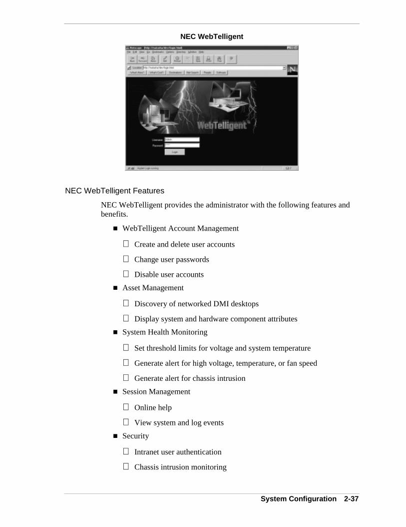
System Configuration 2-37
NEC WebTelligent
NEC WebTelligent Features
NEC WebTelligent provides the administrator with the following features andbenefits.
! WebTelligent Account Management
Create and delete user accounts
Change user passwords
Disable user accounts
! Asset Management
Discovery of networked DMI desktops
Display system and hardware component attributes
! System Health Monitoring
Set threshold limits for voltage and system temperature
Generate alert for high voltage, temperature, or fan speed
Generate alert for chassis intrusion
! Session Management
Online help
View system and log events
! Security
Intranet user authentication
Chassis intrusion monitoring
2-38 System Configuration
! Reduced Costs
WebTelligent is free with the purchase of an NEC PowerMateManaged system
WebTelligent is free to download from the NEC CSD website(www.nec-computers.com).
NEC WebTelligent Requirements
WebTelligent installs on a Windows 98, Windows 2000, or Windows NT webserver with the following minimum configuration:
! Intel Celeron microprocessor
! 32 MB of random access memory
! 20 MB of hard drive space
! Microsoft Windows 98, Windows 2000, or Windows NT 4.0 OperatingSystem and associated web server software
Microsoft Windows 98 or Windows 2000 with Microsoft PersonalWeb Server version 1.0 or later
Microsoft Windows NT with Peer Web Server version 2.0 or later
Microsoft Windows NT with Microsoft Internet Information Serverversion 3.0 or later
Microsoft Windows NT with Netscape FastTrack Server version 2.0or later or Netscape Enterprise version 3.01 or later
! One or more Internet Browsers
Microsoft Internet Explorer 4.0 or later
Netscape Navigator Gold 3.03 or later
Netscape Communicator 4.0 or later
! TCP/IP.
WebTelligent works with networked desktop computers having the followingminimum configuration:
! Intel Celeron microprocessor
! 32 MB of random access memory
! Microsoft Windows 98, Windows 2000, or Windows NT 4.0 operatingsystem
! Intel LDCM 3.32
! DMI version 2.0
System Configuration 2-39
! NEC Auto-Discovery Agent
! TCP/IP.
NEC WebTelligent Installation
Install the WebTelligent software and the NEC Auto Discovery Agent softwareon a Windows 98, Windows 2000, or Windows NT web server as follows.
1. Close all open applications before installing WebTelligent and AutoDiscovery Agent.
2. Install the web server software on a machine with a host name such asPowerMate-A. Set up the web server as follows.
! Install your web server software — Microsoft Personal Web Server orother software (see the preceding list).
! On the taskbar, click Start, point to Settings, and click Control Panel.
! At the Control Panel, double click Personal Web Server.
! In Personal Web Server, click the Administration tab.
! In Administration, click Administration to start the web browser.
Note: If the web browser does not start, click theStartup tab, click Start, click the Administration tab, andclick Administration to start the browser.
3. Install the WebTelligent software on the web server.
Note: WebTelligent software is available on the NECApplication and Driver CD. The software can also bedownloaded from the NEC CSD website(www.nec-computers.com).
! For systems with WebTelligent on the NEC Application and Driver CD,see “Installing ToolTelligent Utilities.”
! If downloading the WebTelligent software from the NEC CSD website(www.nec-computers.com), save the download file in your C:\Tempdirectory or other appropriate directory. Double click setup.exe, andfollow the prompts.
4. Configure the installation.
! Follow the WWW Administration link, click the Directories tab, andedit the home page.
! Modify the directory entry to C:\ProgramFiles\PBNEC\WebTelligent\html and click OK.

2-40 System Configuration
! Scroll to the bottom of the page and set the default document tologin.html.
! Click OK.
5. Install the NEC Auto Discovery Agent software on a managed client.
! If installing the Auto Discovery Agent from the NEC Application andDriver CD, see “Installing ToolTelligent Utilities.”
! If downloading the Auto Discovery Agent software from the NEC CSDwebsite (www.nec-computers.com), save the download file in yourC:\Temp directory or other directory. Double click setup.exe, andfollow the prompts.
Note: Before installing the NEC Auto Discovery Agentsoftware on a client, check to see if it is already installed.Look for the directory C:\Programfiles\PBNEC\WebTelligent Discovery Agent. If it’s notthere, install the software from the NEC Application andDriver CD or download from the NEC CSD website(www.nec-computers.com).
6. Open WebTelligent as follows.
Note: LDCM 3.32 or later must be installed on everyclient.
! At a managed desktop computer, start a web browser. Set the URL tothe web server’s machine name (for example: http://PowerMate-A).
! At the Login screen (see the following screen), enter the followinginformation.
At the username field, type Admin.
At the password field, type Admin.
Note that Admin must use a capital A and that the password can bechanged after the first login.

System Configuration 2-41
WebTelligent Login Screen
! Click Login. The WebTelligent control screen displays (see thefollowing screen).
! Click Discover on the WebTelligent screen to collect a list of machinesto manage.
! Click on the desktop to be managed.
! A Workstation screen opens to display a summary of the workstationattributes.
! When finished, click File and click Close to go back to the Windowsscreen.
NEC WebTelligent Control Screen

2-42 System Configuration
NEC SNMP Agent
The NEC Desktop Simple Network Management Protocol (SNMP) Agent is anextension to the Microsoft SNMP Agent. The NEC SNMP Agent permits anetwork administrator to manage NEC PowerMate clients.
The NEC SNMP Agent performs the following major functions:
! Assets Management — displays system serial number, product model,and more.
! Configuration Management — displays memory size and more.
! Help Desk Support — provides information such as BIOS versions.
! Alert Notification — provides alerts when thresholds are exceeded (forexample, when temperatures exceed specified limits in a computer).
SNMP-managed devices on a network send messages (traps) when a preset levelof device activity occurs. Notification of events with SNMP traps is sent to anetwork manager upon reaching either a user-specified over-threshold or under-threshold condition for any supported management information base (MIB)variable.
The following sections describe how to install and configure the NEC SNMPAgent on systems running the Microsoft Windows 98, Windows 2000, orWindows NT operating system.
Installing the NEC SNMP Agent
Install the NEC SNMP Agent on the Windows 98, Windows 2000, or WindowsNT operating system as follows.
Do not install both the NEC SNMP Agent and LANDeskClient Manager on the same computer.
Do not install both the NEC SNMP Agent and LANDesk Client Manager on thesame computer. The two applications are incompatible, and neither can beremoved using the uninstall utility. To remove them, a full restore must beperformed after which all applications must be reinstalled.
The NEC SNMP Agent and the NEC WebTelligent software are each installedusing a Setup.exe program launched from a subdirectory on the NECApplications and Driver CD. Install the applications without regard to the orderin which the other applications are installed.
Note: Install the NEC SNMP Agent software from theNEC Application and Driver CD or download the softwarefrom the NEC CSD website (www.nec-computers.com).

System Configuration 2-43
1. If installing the NEC SNMP Agent from the NEC Application and DriverCD, see “Installing ToolTelligent Utilities” for installation instructions.
2. If downloading the software from the NEC CSD website(www.nec-computers.com), save the download file in the C:\Tempdirectory or other appropriate directory. Double click setup.exe and followthe prompts.
Configuring the NEC SNMP Agent for Windows 98 or Windows 2000
The SNMP Agent is configured with the Windows Policy Editor. The PolicyEditor configures the traps, communities, and other policies.
Use the Policy Editor to configure the traps, communities, and other policies asfollows.
1. In the Windows taskbar, click Start, and point to Programs, Accessories,and System Tools. Click System Policy Editor.
2. At the “System Policy Editor,” click File and point to Open Registry.Double click Local Computer.
3. Expand Network and expand SNMP to display the list of policies. Thepolicies are:
! Communities — Specifies one or more groups of hosts that thiscomputer belongs to and that can be managed with SNMP.
! Permitted Managers — Limits the set of SNMP managementapplications that can access this computer to those with the IP or IPXaddresses that the user provides.
! Traps for “Public” Community — Limits the set of computers thatreceive traps from this computer to those with the IP or IPX addressesthat the user provides.
Note: For an SNMP management console, such as theNEC SNMP Desktop Manager and HP OpenView, IPaddresses (for example, 157.123.176.100) must be enteredin the Traps for “Public Community” to receive traps from theNEC SNMP agents.
For the NEC SNMP Agent to send a trap to the NEC SNMPDesktop Manager, the port number can be configured fromthe registry: "HKEY_LOCAL_MACHINE\SOFTWARE\NEC Computer Systems Division\NEC SNMP DesktopAgent\Port Number". The default port number is set to55593.
! Internet MIB (RFC 1156) — Allows the user to specify a contact nameand location for the Internet MIB.

2-44 System Configuration
4. Check each policy required and highlight the policy name.
! For Communities, Traps, and Permitted Managers, click Show andconfigure the policy as appropriate.
! Highlighting the Internet MIB policy opens the contact name andlocation fields in the Policy window for editing.
! Click File and click Save.
! Click File and click Exit.
Configuring the NEC SNMP Agent for Windows NT
Configure the NEC SNMP Agent for Windows NT as follows.
1. In the Windows taskbar, click Start, point to Settings, and click ControlPanel.
2. At the Control Panel, double click the Network icon.
3. At the Network screen, click the Services tab and click Add.
4. At the Select Network Services screen, highlight SNMP Service, and clickOK.
5. At the Microsoft SNMP Properties screen, set the following three properties:
! Security — Limits the set of computers than can perform SNMPmanagement on this computer to those in the community and/or specificcomputer names the user provides.
! Traps — Limits the set of computers that receive traps from thiscomputer to those in the community and/or specific computer names theuser provides.
Note: For an SNMP management console, such as theNEC SNMP Desktop Manager and HP OpenView, IPaddresses (for example, 157.123.176.100) must be enteredin the Traps for “Public Community” to receive traps from theNEC SNMP agents.
For the NEC SNMP Agent to send a trap to the NEC SNMPDesktop Manager, the port number can be configured fromthe registry: "HKEY_LOCAL_MACHINE\SOFTWARE\NEC Computer Systems Division\NEC SNMP DesktopAgent\Port Number". The default port number is set to55593.
! Agent — Allows the user to specify a contact name and location for thecomputer.

System Configuration 2-45
6. Edit the properties.
7. Click OK to return to the Network screen.
8. Click Close to return to the Windows screen.
NEC Configuration Change Notification
NEC Configuration Change Notification is an application that runs as Windowsstarts. It works with the LANDesk application and DMI (Desktop ManagementInterface) software to determine if there has been a change in the processor,main memory, or hard drive since the last startup. A message appears on thescreen when a change is detected.
Install NEC Configuration Change Notification from the NEC Application andDriver CD. For installation information, see “Installing ToolTelligent Utilities.”
NEC Auto Backup Utility
The NEC Auto Backup utility works with LANDesk Client Manager andCheyenne Backup to detect predicted hard drive failures and to automaticallyback up the data from the failing drive. The utility only works with SMARThard drives and it requires both LANDesk Client Manager and CheyenneBackup to function.
The Auto Backup utility runs from the Startup group on the Windows Startmenu. The utility has some configuration options that are accessible through thesystem tray icon. The NEC Tools group on the Start menu includes a Read Mefile containing recent information about the utility as well as access to a Helpdocument.
Cheyenne Backup configuration determines the exact nature of the backup thatwill be performed automatically. See the online Help for Cheyenne BackupConfiguration for information about available options.
Install the NEC Auto Backup Utility from the NEC Application and Driver CD.For installation information, see “Installing ToolTelligent Utilities.”

3Disassembly and Reassembly
! Hard Drive
! SO-DIMM Module
! Bottom Cover
! CD-ROM Drive
! Diskette Drive
! System Board and Support Plate
! Support Plate
! Network Board
! LAN Connector Board
! PC Card Bay
! CPU Fan
! CMOS Battery
! Processor and Heat Sink
! Hard Drive Bay and Drive
! LCD Panel

3-2 Disassembly and Reassembly
This section contains step-by-step disassembly procedures for the PowerMate2000 series system. A disassembly figure is provided with most procedures.Section 5 includes a field-level parts list and an illustrated parts breakdownshowing an exploded view of the system.
A small flat head screwdriver and a small Phillips-head screwdriver are the onlyrequired tools. For complete disassembly of the system unit, follow thedisassembly order listed in the following table. To reassemble, follow the tableand procedures in reverse order. Where reassembly is not readily apparent,reassembly procedures are provided.
PowerMate 2000 Series Disassembly Sequence
Sequence Part Name See Page
1 Hard Drive 3-3
2 SO-DIMM Memory Module(s) 3-5
3 Bottom Cover 3-7
4 CD-ROM Drive 3-8
5 Diskette Drive 3-9
6 System Board and Support Plate Assembly 3-10
7 Support Plate 3-12
8 Network Board Assembly 3-13
9 LAN Connector Board 3-14
10 PC Card Bay 3-14
11 CMOS Battery 3-15
12 CPU Fan 3-16
13 Processor and Heat Sink 3-17
14 Hard Drive Bay and Drive 3-20
12 LCD Panel 3-20
When disassembling the system, follow these general rules.
! Turn off the system and disconnect the AC power adapter and power cordfrom the power source and system unit.
! Disconnect all peripherals before disassembling the system.
! Before opening the system unit or handling boards or chips, touch themetal bottom cover on the system unit to discharge static.
! Do not disassemble parts other than those specified in the procedure.
! All screws are Phillips-head, unless otherwise specified.
! Observe each cable connector before attempting to disconnect. Someconnectors have a retainer holding them in place.

Disassembly and Reassembly 3-3
! Use extreme care in disconnecting and connecting cables to preventbreakage. Do not pull on the cable, pull only on the connector.
! Label any cable connector before removing it. Note where the connectorgoes and in what position it was installed.
On completion of any reassembly, perform a power-on test. If a fault occurs,verify that the reassembly was performed correctly.
Before handling boards or chips, ground yourself to releasestatic.
Hard Drive RemovalRemove the 2 1/2-inch hard drive as follows.
1. Close all applications, shut down the operating system, turn off system unitpower, and unplug the AC power adapter and power cable from the powersource and the back of the system unit.
2. Turn off and disconnect all peripherals.
3. Position the system unit so that the right side is facing you. Swivel the LCDpanel away from the side so that is not blocking your view of the side.
4. Remove the hard drive panel by carefully prying out the panel with yourfinger. Use care to prevent marring of the system unit.
Removing the Hard Drive Panel
A – Right Side C – PanelB – Pry Point
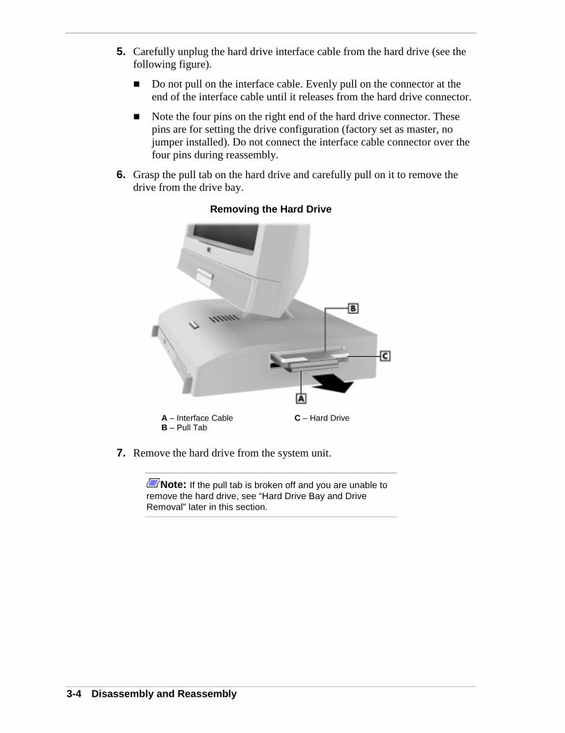
3-4 Disassembly and Reassembly
5. Carefully unplug the hard drive interface cable from the hard drive (see thefollowing figure).
! Do not pull on the interface cable. Evenly pull on the connector at theend of the interface cable until it releases from the hard drive connector.
! Note the four pins on the right end of the hard drive connector. Thesepins are for setting the drive configuration (factory set as master, nojumper installed). Do not connect the interface cable connector over thefour pins during reassembly.
6. Grasp the pull tab on the hard drive and carefully pull on it to remove thedrive from the drive bay.
Removing the Hard Drive
A – Interface Cable C – Hard DriveB – Pull Tab
7. Remove the hard drive from the system unit.
Note: If the pull tab is broken off and you are unable toremove the hard drive, see “Hard Drive Bay and DriveRemoval” later in this section.

Disassembly and Reassembly 3-5
SO-DIMM Module RemovalRemove the SO-DIMM module(s) as follows.
1. Close all applications, shut down the operating system, turn off systempower, and unplug the AC power adapter and power cord from the powersource and the back of the system unit.
2. Turn off and disconnect all peripherals.
To prevent damage to the LCD panel screen whenperforming step 3, ensure that your work surface is clean,flat, smooth, and free of any objects before positioning thesystem face down.
3. Carefully position the system with the LCD panel face down on a clean, dry,smooth surface and with the bottom of the system unit facing you.
4. Remove the single screw holding the SO-DIMM panel in place on thebottom of the system unit. Set the panel aside.
Removing the SO-DIMM Module Panel
A – Access Panel B – Screw

3-6 Disassembly and Reassembly
5. Press outward on the two SO-DIMM locking clips to release the module.The module pops up at an angle, ready for removal.
Releasing the SO-DIMM Module
A – Locking Clips
6. Carefully pull the module out of its socket and store in a static free bag.
7. To install a module, align the notch in the module with the key in the slotand carefully slide the module into the socket at an angle. Press down on themodule until the clips lock it in place.
Installing a SO-DIMM Module
A – SO-DIMM Module C – SocketB – Notch D – Clip (1 of 2)

Disassembly and Reassembly 3-7
Bottom Cover RemovalRemove the bottom cover from the system unit as follows.
1. Close all applications, shut down the operating system, turn off systempower, and unplug the AC power adapter and power cord from the powersource and the back of the system unit.
2. Turn off and disconnect all peripherals.
To prevent damage to the LCD panel screen whenperforming step 3, ensure that your work surface is clean,flat, smooth, and free of any objects.
3. Carefully position the system with the LCD panel face down on a clean, dry,smooth surface and with the bottom of the system unit facing you.
4. Remove ten Phillips head screws holding the bottom cover to the systemunit. It is not necessary to remove the SO-DIMM panel from the cover.
Removing the Bottom Cover
A – Bottom Cover B – Screw (1 of 10)
5. Set the screws and bottom cover aside.

3-8 Disassembly and Reassembly
CD-ROM Drive RemovalRemove the CD-ROM drive as follows.
1. Remove the system unit bottom cover (see “Bottom Cover Removal” earlierin this section).
2. Disconnect the CD-ROM drive interface cable from its connector on thedrive.
! Release the cable retainer on the drive connector by gently pushing theends of the retainer away from the connector.
! Carefully pull the cable out of the drive connector.
Removing the CD-ROM Drive
A – CD-ROM Drive D – Drive ConnectorB – Cable Retainer E– Support PlateC – Interface Cable F – Screws (4)
3. Remove the four screws securing the drive to the support plate.
4. Remove the CD-ROM drive from the system unit.
5. As required, remove the drive interface connector board from the drive byremoving one screw and unplugging the connector board from its connectoron the drive.

Disassembly and Reassembly 3-9
Diskette Drive RemovalRemove the diskette drive as follows.
1. Remove the system unit bottom cover (see “Bottom Cover Removal”).
2. Remove the four screws securing the diskette drive to the support plate (seethe following figure). Hold the drive in place and perform step 3.
3. While holding the diskette drive, move it out enough to carefully unplug thediskette drive interface cable from its connector on the system board.
Removing the Diskette Drive
A – Diskette Drive D – Support PlateB – Interface Cable Connector E – Screws (4)C – Interface Cable
4. Remove the diskette drive from the system unit.

3-10 Disassembly and Reassembly
System Board and Support Plate AssemblyRemoval
Remove the system board and support plate assembly as follows.
Note: The system board and support plate assemblymust be removed from the system unit to remove thenetwork board, processor, CPU fan, PC card bay, CMOSbattery, or LCD panel.
1. Remove the system unit bottom cover (see “Bottom Cover Removal” earlierin this section).
2. Remove the CD-ROM drive and diskette drive (see “CD-ROM DriveRemoval” and “Diskette Drive Removal” earlier in this section).
3. Remove any PC cards or PC card slot covers that may be installed.
! Press the PC card eject button(s) to eject the cards or slot covers.
! Remove the cards or slot covers from the system unit.
! Press in the eject buttons so that they are not in the extended position.
4. Unplug the interface cable from the hard drive (see “Hard Drive Removal”earlier in this section). It is not necessary to remove the hard drive.
5. Remove seven screws and one standoff securing the system board andsupport plate assembly to the system unit chassis.
Removing the System Board and Support Plate Assembly
A – System Board C – Screw (1 of 7)B – Support Plate D– Standoff (1)

Disassembly and Reassembly 3-11
6. Carefully pull the system board and support plate assembly out just enoughto access the LCD panel interface cable and speaker cable on the oppositeside of the assembly.
You might need to pull out on the right side of the system unit chassis torelease the volume control from its slot in the side of the chassis.
7. Carefully unplug the LCD panel interface cable from connector P11 on thesystem board. Use a steady pull on each end of the connector. Do not pull onthe cable.
8. Carefully unplug the LCD speaker cable from connector P12 on the systemboard. Use a steady pull on each end of the connector. Do not pull on thecable.
9. Remove the system board and support plate assembly from the system unitchassis and set the assembly on a clean, smooth static free surface.

3-12 Disassembly and Reassembly
Support Plate RemovalRemove the support plate from the system board as follows.
Note: The support plate must be removed from thesystem board to remove the network board, CPU fan, PCcard bay, or CMOS battery. The support plate does not needto be removed if removing the processor and heat sink.
1. Remove the system board and support plate assembly (see “System Boardand Support Plate Removal” earlier in this section).
2. Position the assembly so that the network board side of the system board isfacing up (see the following figure).
3. Remove the screw (B) securing the support plate (A) and network board (C)to the system board.
4. Slide the black plastic shield (F) out of the PC card bay (G) to access thespecial screw (E).
5. Remove the special screw (E) securing the system board to the support plate.Be sure to use this screw when reassembling the support plate to the circuitboard.
6. Lift the system board off the support plate and set the board on a static freesurface. Use care to prevent damage to the diskette drive and CD-ROMdrive cables on the system board.
Removing the Support Plate Mounting Screws
A – Support Plate E – Special ScrewB – Network Board Screw F – Plastic ShieldC – Network Board G – PC Card BayD – System Board

Disassembly and Reassembly 3-13
Network Board Assembly RemovalRemove the network board, cable, and bracket assembly from the system boardas follows.
1. Remove the support plate from the system board (see “Support PlateRemoval” earlier in this section).
2. Position the system board with the network board facing up.
3. Unplug the network board cable from its connector (D) on the LANconnector board (see the following figure).
4. Remove the network board retaining screw (A) from the system board asfollows.
! Turn the system board over.
! Remove the network board screw (A).
! Turn the system board back over, with the network board side facing up.
Removing the Network Board
A – Screw D – Network Board Cable ConnectorB – Network Board E – LAN Connector BoardC – System Board
5. Unplug the network board from the system board and remove the networkboard, bracket, and cable assembly from the system board.
6. As necessary, remove the bracket and cable from the board.

3-14 Disassembly and Reassembly
LAN Connector Board RemovalRemove the LAN connector board from the system board as follows.
1. Remove the support plate from the system board (see “Support PlateRemoval” earlier in this section).
2. Position the system board with the network board side facing up.
3. Unplug the network board cable from connector (D) on the LAN connectorboard (see the preceding figure “Removing the Network Board”).
4. Remove the screw holding the LAN connector board to the connector frameand remove the board.
PC Card Bay RemovalRemove the PC card bay as follows.
1. Remove the support plate from the system board (see “Support PlateRemoval” earlier in this section).
2. Position the system board with the network board side facing down.
3. Remove the four screws securing the PC card bay to the system board.
Removing the PC Card Bay
A – PC Card Bay Screws (4) C – CMOS BatteryB – CPU Fan Connector P22
4. Turn the board over with the network board side facing up.
5. Unplug the PC card bay from connector P13 on the system board andremove the bay from the board.

Disassembly and Reassembly 3-15
CMOS Battery RemovalRemove the 3-volt lithium battery from the system board as follows.
1. Remove the support plate from the system board (see “Support PlateRemoval” earlier in this section).
2. Turn the system board over with the network board side facing down andlocate the battery (see the preceding figure “Removing the PC Card Bay” forbattery location).
3. Insert a small flat blade screwdriver in front of pry point (B) and carefullypry up on the battery to release it from its socket.
Removing the Battery
A – Battery B – Pry Point
The battery can explode if it is incorrectly replaced orimproperly discarded. Use only the same battery or anequivalent type recommended by the manufacturer whenreplacing the battery.
Lithium acts as a catalyst when exposed to water andcauses spontaneous combustion on contact. Discard usedbatteries according to the manufacturer’s instructions.
4. Remove the battery and discard it in accordance with the manufacturer’sinstructions.
5. With the positive (+) side facing up, press the new battery into the socket.
6. After reassembling the system unit, run Setup to reconfigure systemparameters (see Section 2, “System Configuration”) according to the settingspreviously recorded.

3-16 Disassembly and Reassembly
CPU Fan RemovalRemove the CPU fan as follows.
1. Remove the support plate from the system board (see “Support PlateRemoval” earlier in this section).
2. Position the system board with the network board side facing down.
3. Unplug the CPU fan cable from connector P22 on the system board (see thepreceding figure “Removing the PC Card Bay” for the location of P22).
4. Turn the system board over, with the network board side facing up.
5. Remove the two screws securing the CPU fan to the heat sink.
Removing the CPU Fan
A – CPU Fan B – Screws (2)
6. Remove the CPU fan from the heat sink.

Disassembly and Reassembly 3-17
Processor and Heat Sink RemovalThe Celeron processor is installed in a Slot370 socket and is cooled by acombination of a heat sink attached to the top of the processor and the CPU fan.
Remove the heat sink and processor as follows.
If the system was just running, the processor and heat sinkon the system board are hot. To avoid a burn, let thecomponents cool for 10 minutes before continuing.
Before handling components, reduce static discharge bytouching a metal part on the chassis.
1. Remove the system board and support plate assembly (see “System Boardand Support Plate Assembly Removal” earlier in this section. It is notnecessary to remove the support plate.
2. Position the system board with the processor side facing up and the supportplate facing down.
3. Remove the two screws holding the CPU fan to the processor heat sink (seethe following figure). Move the fan aside.
It is not necessary to unplug the fan from its connector unless replacing thefan (if replacing, see “CPU Fan Removal” earlier in this section).
4. Remove the retention clip from the heat sink and processor as follows (seethe following figure).
! Simultaneously press down on the left end of the retention clip whilecarefully pulling out the left end to unhook it from the processor sockettab.
! Remove the retention clip from the tab on the other end of the processorsocket. Set the clip aside.
5. Remove the heat sink from the processor.

3-18 Disassembly and Reassembly
Removing the Processor and Heat Sink
A – Heat Sink D – Retention ClipB – Socket Tab (1 of 2) E – CPU FanC – Lock Lever (under heat sink) F – CPU Fan Screws (2)
6. Remove the processor as follows.
! Pull out on the processor socket lock lever just enough to release thelever from the socket, then pivot the lever up to release the processor.
! Carefully lift up on the processor and remove it from the socket. Storethe processor in a static free bag.
7. Install a replacement processor as follows.
! Align the notched corner of the processor with the corresponding notchon the socket. A white triangle on the board points to the notch on thesocket.
! Carefully align the processor pins with the socket pin holes and set theprocessor into the socket.
! Pivot the lock lever down and press it in towards the socket until it locksin place.
Disassembly and Reassembly 3-19
8. Install a replacement heat sink as follows and in accordance with theprocedures contained in the heat sink kit.
Using the wrong heat sink or no heat sink can damage theprocessor, system board, or both. Ensure that thereplacement processor has the correct heat sink (refer to thedocumentation that comes with the kit).
Additional installation information can be obtained from NECCSD (see Section 8, “NEC CSD Information Services” forinformation on contacting NEC CSD).
! Center a new thermal pad on top of the processor.
! Align the heat sink with the processor and set it down on the pad andprocessor (see the above figure for alignment).
9. Attach the heat sink retention clip by hooking the right end of the clip overthe socket tab. Press the other end of the clip over the tab on the oppositeside of the socket until the clip snaps in place.
10. Attach the CPU fan to the heat sink with the two previously removedscrews.

3-20 Disassembly and Reassembly
Hard Drive Bay and Drive RemovalRemove the hard drive bay and the hard drive as follows.
1. Remove the system board and support plate assembly (see “System Boardand Support Plate Assembly Removal” earlier in this section).
2. Remove the four screws securing the drive bay to the chassis (see the nextfigure “Removing the LCD Panel” for bay and screw locations).
3. Remove the bay and the drive from the chassis.
LCD Panel RemovalRemove the LCD panel from the system unit as follows.
Note: The LCD panel is a whole unit replaceable item.There are no field replaceable parts within the LCD panel.The LCD panel must be returned to the factory for repair.
1. Remove the system board and support plate assembly (see “System Boardand Support Plate Assembly Removal” earlier in this section).
2. Carefully cut the cable tie around the LCD panel interface cable and switchcable (see the following figure).
3. Remove the four screws securing the collar and system unit chassis to theLCD panel.
Removing the LCD Panel
A – Drive Bay Screw (1 of 4) E – Interface CableB – Drive Bay F – Cable TieC – Collar G – Switch CableD – LCD Panel Screw (1 of 4)

Disassembly and Reassembly 3-21
4. Carefully pull the LCD panel out of its mount on top of the system unitchassis.
5. Carefully pull the interface cable and switch cable through the collar in thesystem unit chassis. Set the LCD panel down on a clean, flat surface.
6. Install the LCD panel as follows.
! Align the collar inside the system unit chassis so that the collar tab ispointing toward the power switch.
! From the outside of the system unit chassis, insert the LCD panel cablesthrough the chassis collar.
! Align the three guide pins on the LCD panel collar with the guide pinholes in the LCD mount on the outside of the chassis (see the followingfigure).
! Insert the LCD panel stem into the LCD mount on the outside of thechassis. Ensure that the guide pins are in the pin holes.
! Check that the LCD panel stem is fully seated in the chassis mount.
! Secure the LCD panel to the system unit with the four previouslyremoved screws.
Installing the LCD Panel
A – LCD Panel Collar D – Chassis CollarB – Guide Pins (2 of 3) E – LCD MountC – Guide Pin Holes (3)

3-22 Disassembly and Reassembly
7. Check that the LCD panel swivels side-to-side and tilts up and down. If itdoes not, check the alignment of the collar tab.
8. Secure the cables with a cable tie inserted through the hole in the hard drivebay and around the cables. Do not snug up the cable tie. Leave enough slackin the tie to allow cable movement as the LCD panel is positioned side-to-side.
9. Install the system board and plate assembly.

4System Board
! Connectors
! Jumpers
! Sockets
! Components

4-2 System Board
This section describes the locations of connectors, jumpers, and sockets on thesystem board, including external cable connectors, internal board connectors,jumper locations, and upgrade sockets.
Included in this section are procedures for setting jumpers on the system boardand a SO-DIMM memory upgrade path for the SO-DIMM sockets. Alsoincluded are descriptions of system board components.
Connectors, Jumpers, and SocketsThe following paragraphs describe the system board external cable connectorlocations, internal board connector locations, jumper locations, and upgradesockets. Included are procedures for setting jumpers on the system board and atable showing the upgrade path for the SO-DIMM sockets.
External Cable Connectors
Locations of the external cable connectors on the system board at the back of thesystem unit are shown in the following figure. For descriptions of theconnectors, see Section 1, “System Overview.”
System Board External Cable Connector Locations
A – Mouse Port F – VGA ConnectorB – Kensington Lock Slot G – LAN ConnectorC – Keyboard Port H – USB ConnectorsD – Printer Port 1 I – DC Power ConnectorE – Serial Port
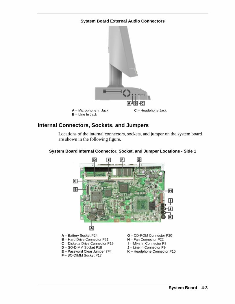
System Board 4-3
System Board External Audio Connectors
A – Microphone In Jack C – Headphone JackB – LIne In Jack
Internal Connectors, Sockets, and Jumpers
Locations of the internal connectors, sockets, and jumper on the system boardare shown in the following figure.
System Board Internal Connector, Socket, and Jumper Locations - Side 1
A – Battery Socket P24 G – CD-ROM Connector P20B – Hard Drive Connector P21 H – Fan Connector P22C – Diskette Drive Connector P19 I – Mike In Connector P8D – SO-DIMM Socket P18 J – Line In Connector P9E – Password Clear Jumper 7F4 K – Headphone Connector P10F – SO-DIMM Socket P17

4-4 System Board
System Board Internal Connector and Socket Locations - Side 2
A – CardBus Connector P13 G – Serial Port Connector P04B – DC Power Connector P07 H – Parallel Port Connector P03C – USB Connector P06 I – Keyboard Port P02D – Speaker Connector P12 J – Mouse Port P01E – VGA Connector P05 K – LAN Connector P15F – LCD Panel Connector P11 L – Socket370 (under heat sink)
System Board Jumpers
The system board contains one field usable jumper block (Clear Passwordjumper 7F4) and two jumper blocks (2F19 and HE5) for factory use. Jumperblocks 2F19 and HE5 should not be changed.
The preceding figure “System Board Internal Connector, Socket, and JumperLocations - Side 1” shows the location of jumper block 7F4 on the systemboard. To set the jumper block, see the following paragraph.
Clearing the Password
If the password needs to be cleared and reset, set jumper block 7F4 as follows.
Jumpers are set correctly at the factory for the systemconfiguration. Only change (or check) the appropriatejumper setting if you forgot your password or want to changethe password.
1. Power off and unplug the system and any peripherals.
The system power must be off before opening the systemand changing a jumper setting.
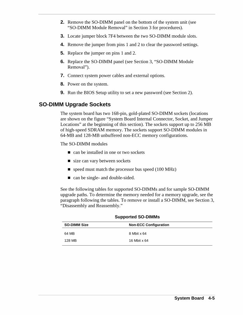
System Board 4-5
2. Remove the SO-DIMM panel on the bottom of the system unit (see“SO-DIMM Module Removal” in Section 3 for procedures).
3. Locate jumper block 7F4 between the two SO-DIMM module slots.
4. Remove the jumper from pins 1 and 2 to clear the password settings.
5. Replace the jumper on pins 1 and 2.
6. Replace the SO-DIMM panel (see Section 3, “SO-DIMM ModuleRemoval”).
7. Connect system power cables and external options.
8. Power on the system.
9. Run the BIOS Setup utility to set a new password (see Section 2).
SO-DIMM Upgrade Sockets
The system board has two 168-pin, gold-plated SO-DIMM sockets (locationsare shown on the figure “System Board Internal Connector, Socket, and JumperLocations” at the beginning of this section). The sockets support up to 256 MBof high-speed SDRAM memory. The sockets support SO-DIMM modules in64-MB and 128-MB unbuffered non-ECC memory configurations.
The SO-DIMM modules
! can be installed in one or two sockets
! size can vary between sockets
! speed must match the processor bus speed (100 MHz)
! can be single- and double-sided.
See the following tables for supported SO-DIMMs and for sample SO-DIMMupgrade paths. To determine the memory needed for a memory upgrade, see theparagraph following the tables. To remove or install a SO-DIMM, see Section 3,“Disassembly and Reassembly.”
Supported SO-DIMMs
SO-DIMM Size Non-ECC Configuration
64 MB 8 Mbit x 64
128 MB 16 Mbit x 64

4-6 System Board
Sample SO-DIMM Upgrade Paths
Total SystemMemory SO-DIMM 0 SO-DIMM 1
64 MB 64 MB --
128 MB 64 MB 64 MB
128 MB 128 MB --
192 MB 128 MB 64 MB
256 MB 128 MB 128 MB
If you do not know how much memory is installed in the system, check theamount as follows.
1. On the Windows 98, Windows 2000, or Windows NT 4.0 desktop, point toMy Computer and click the right mouse button.
2. With the left mouse button, click Properties. Select the General tab toshow the amount of random access memory (RAM) in the computer. ForWindows 98 and Windows 2000, you can also select the Performance tabto show the RAM memory.
Note: If a discrepancy is found in the amount of memorydisplayed at the Power-On Self-Test or in Windows with theamount of memory installed, check that the memorymodules were installed correctly.
ComponentsThe system board has the following features:
! Intel 810 chip set is used for AGP, PCI/ISA, memory, and peripheralcontrol. The chip set incorporates
82801 I/O Controller Hub
82802 Firmware Hub
82810 Graphics Memory Controller Hub
System Manageability Bus
Integrated Audio-Codec 97 sound controller
Dynamic Video Memory Technology (DVMT).
! 64 MB to 256 MB of SDRAM upgradeable with 64-MB or128-MB SO-DIMM modules through two sockets on the system board
System Board 4-7
! Phoenix® Technologies Ltd BIOS in a flash memory device supportingsystem setup and PCI auto-configuration
! 32-KB internal dual write-back cache and 128-KB write-back secondarycache memory integrated on the processor
! pipelined 32-bit addressing
! 64-bit data
! Setup utility built into the BIOS
! 4-Mb Flash ROM for fast economical BIOS upgrades
! power management with power saving mode, featuring inactivity timer
! external connectors for connecting the following external devices:
VGA-compatible monitor (standard, super, high-resolution VGA) toAGP port on system board. Supports resolutions up to 1024 x 768pixels with up to 16.8 million colors.
personal system/2 (PS/2®)-style mouse
PS/2-style keyboard
bi-directional Enhanced Parallel Port (EPP) and EnhancedCapabilities Port (ECP) support for a parallel printer
serial device through one buffered 16C550 UART serial port,supporting up to 115.2 KB per second
two USB devices for connecting up to 127 USB devices
LAN connector for network connection
connectors for optional headphone and microphone (headphone, lineout, microphone)
two PC card slots for supporting up to two 16-bit or 32-bit Type IIPCMCIA cards.
The following table lists the major components on the system board.

4-8 System Board
System Board Components
Component Function
Processor Celeron 433-MHz processor with 100 MHz FSB
Intel 810 Chip Set:
82801 I/O Controller Hub Uses Accelerated Hub Architecture to make direct connectionfrom graphics and memory to the integrated AC97 controller,IDE controller, and dual USB ports.
Supports PCI bus interface, integrated IDE controller, USB,AC’97 Link for audio and telephone Codecs, interrupt controller,timers, 3.3V operation, power management logic, enhancedDMA controller, real-time clock, SM bus, and Firmware Hub.
Packaged in a 241-pin Ball Grid Array.
82802 Firmware Hub Stores system BIOS and video BIOS, eliminating a redundantnonvolatile memory component. In addition, the 82802 containsa hardware Random Number Generator (RNG). The Intel®RNG provides truly random numbers to enable fundamentalsecurity building blocks supporting stronger encryption, digitalsigning, and security protocols.
Features Intel Platform Compatibility, Firmware Hub HardwareInterface Mode, configurable interfaces, flash memory for non-volatile storage, and address/address multiplexed interfacemode.
Packaged in a 32-pin PLCC.
82810 Graphics Memory Controller Hub
Uses Intel graphics technology, software drivers, and DirectAGP (integrated AGP) to create vivid 2D and 3D effects andimages. Features integrated Hardware Motion Compensation toimprove video quality and a digital video out port that enablesconnection to space-saving digital flat panel displays.
Features processor and host bus optimized for the Celeronprocessor, integrated DRAM controller, integrated graphicscontroller, 3D graphics visual enhancements, 3D graphicstexturing enhancements, digital video output, integrated 24-bit230 MHz RAMDAC, 2D graphics, arithmetic stretch blittervideo, integrated graphics memory controller, display cacheinterface, arbitration scheme and concurrency, data buffering,power management functions, and support for I/O bridge.
Packaged in a 421-pin Ball Grid Array
Super I/O Controller(SMSC LPC47B277)
The controller provides the following features:Multimode parallel port Centronics compatible (standard mode) Enhanced capabilities port (ECP) Enhanced parallel port (EPP)One RS-232C serial portIntegrated 8042A keyboard controllerIndustry-standard floppy disc controller

System Board 4-9
System Board Components
Component Function
CardBus Controller (TI PCI1420) High performance PCI-to-CardBus controller supporting twoindependent PC card sockets
32-bit transfers at 33 MHz
Supports any combination of 16-bit and 32-bit CardBus PCcards, powered by 5V or 3.3V (see “Advanced Menu” in Section2 to select the voltage).
Internally buffered to allow PC card hot insertion and removalwithout external buffering.
Sound Intel 82801AB (ICHO) with AD1881 chip
PCM 8/16 bit stereo record/playback, sampling rate 8.0 to 48.0KHz, compatible with Windows Sound System
Processor and Secondary Cache
The system uses an Intel Celeron processor with an internal clock speed of 433MHz.
The processor is an advanced pipelined 32-bit addressing, 64-bit data processordesigned to optimize multitasking operating systems. The 64-bit registers anddata paths support 64-bit addresses and data types.
To use the processor’s power, the system features an optimized 64-bit memoryinterface and 128 KB of secondary write-back cache on the processor.
The processor is compatible with 8-, 16-, and 32-bit software written for theIntel386™, Intel486™, Pentium, and Pentium Pro processors. The processor ismounted in a Socket370 connector. A heat sink is attached to the top of theprocessor for cooling.
System BIOS
The PCI-compatible BIOS is contained in a flash memory device on the systemboard. The BIOS provides the Power-On Self-Test (POST), the system Setupprogram, a PCI and IDE auto-configuration utility, and BIOS recovery code.
The system BIOS is always shadowed. Shadowing allows any BIOS routine tobe executed from fast 32-bit DRAM on the system board, instead of from theslower 8-bit flash device.
The Flash ROM allows fast, economical BIOS upgrades. The Flash ROM is areprogrammable EPROM containing both the system and video BIOS. Usingthe Flash ROM to change the ROM BIOS provides the following advantages:
! the BIOS upgrade is performed quickly and easily
! the expense of replacing ROM BIOS chips is eliminated, so systemmaintenance costs are reduced
4-10 System Board
! there is less chance of inadvertently damaging the system board thanwhen physically replacing ROMs
! new technology can be incorporated while maintaining corporatestandards
! network administrators can exercise company-wide control of BIOSrevisions.
The BIOS programs execute the Power-On Self-Test, initialize processorcontrollers, and interact with the display, diskette drive, hard drive,communication devices, and peripherals. The system BIOS also contains theSetup utility. The POST copies the ROM BIOS into RAM (shadowing) formaximum performance.
The Flash ROM allows the system and video BIOS to be upgraded with theBIOS Update utility, without having to physically remove the ROM (seeSection 2 for further information on the BIOS Update utility). The Flash ROMsupports the reprogramming of the system BIOS and the video BIOS.
System Memory
The system comes with between 64 MB and 256 MB of SDRAM installed inSO-DIMM sockets on the system board.
The memory configuration consists of two sockets. The SO-DIMM socketsaccept 168-pin, 64-bit (non-ECC) 64- and 128-MB SO-DIMMs. See“SO-DIMM Sockets” for a list of supported SO-DIMMs.
PCI Local Bus
The 32-bit PCI local bus is the primary I/O bus for the system. The PCI bus is ahighly integrated I/O interface that offers the highest performance local busavailable for the Celeron processor. The bus supports burst modes that sendlarge amounts of data across the bus, allowing fast displays of high-resolutionimages.
The PCI local bus is a high-performance bus that provides a processor-independent data path between the CPU and high-speed peripherals. The PCIbus is a robust interconnect mechanism designed specifically to accommodatemultiple high performance peripherals for graphics and full motion video.
The PCI local bus supports memory transfer rates of over 100 MB per secondfor reads and over 120 MB per second for writes, depending on processorconfiguration.
System Board 4-11
PCI/IDE Port
The system board supports high-performance primary and secondary PCI/IDEports on the system board. The primary PCI/IDE port has an enhanced IDEinterface that supports a PIO Mode 4 device with 16 MB per second 32-bit widedata transfers on the high-performance PCI local bus. The port supports UltraDMA/33.
The installed hard drive is connected to the primary PCI/IDE port connectorwith a signal and power interface cable. The installed CD-ROM drive isconnected to the secondary PCI/IDE port connector with a signal and powerinterface cable.
Parallel Interface
The system has a 25-pin bidirectional parallel port on the system board. Portspecifications conform to the IBM-PC standards. The port supports EnhancedCapabilities Port (ECP) and Enhanced Parallel Port (EPP) modes for devicesthat require ECP or EPP protocols. The protocols allow high-speed bi-directional transfer over a parallel port and increase parallel port functionalityby supporting more devices.
The BIOS has automatic ISA printer port sensing that works with most devices.If the BIOS detects an ISA printer port mapped to the same address, the built-inprinter port is disabled. (Verify in the BIOS Setup that printer ports mapped tothe same address are enabled or disabled appropriately.) The BIOS also sets thefirst parallel interface port it finds as LPT1 and the second port it finds as LPT2.The interrupt is set at IRQ7 via the BIOS Setup utility. Software-selectable baseaddresses are 228h, 378h, and 278h.
Sets of I/O addresses for the parallel port are given in the following table (seeSection 2, “System Configuration,” for interrupt levels). This is a list of allpossible configurations. The parallel port uses only one set.
Parallel Port Addresses
Starting I/O Address Port
378 LPT1
278 LPT2
228 LPT3
378 LPT1
278 LPT2
228 LPT3
Parallel interface signals are output through the system board’s 25-pin,D-subconnector. The connector is located at the back of the system unit.

4-12 System Board
Serial Interface
The system has one 16C550 UART compatible serial port (COM1) integratedon the I/O controller. The serial port supports the standard RS-232C interface.The buffered high-speed serial port supports transfer rates up to 115.2 KB. Theport allows the installation of high-speed serial devices for faster data transferrates.
The I/O addresses for the channel is given in the following table (see Section 2,“System Configuration,” for interrupt levels). Soft-selectable base addresses are3F8h, 2F8h, 3E8h, and 2E8h.
Serial Port I/O Addresses
Starting I/O Address Port
3F8 COM1
2F8 COM2
3E8 COM3
2E8 COM4
See Section 2, “System Configuration,” for information on resetting the portthrough the BIOS Setup utility. See Section 9, “Specifications,” for the serialinterface specifications.
Serial interface signals are output through the system board’s 9-pin,D-subconnector. The connector is located at the back of the system unit.
USB Interface
The Universal Serial Bus (USB) ports allow new Plug and Play serial devices tobe added without having to open the system. One USB device may be pluggedinto each USB port for direct system connection. With a hub and the propercabling, up to 127 USB devices can be addressed by the system. The USBdetermines system resources for each peripheral and assigns them without userintervention. Boot support for a USB keyboard is present so the system can bebooted with a USB keyboard instead of a standard keyboard.
Accelerated Graphics Port
The system board contains a direct integrated accelerated graphics port (DirectAGP) that supports graphics-intensive, 3D applications. The Direct AGPoperates independently of the PCI bus and supports 133-MHz data transfer rates,allowing 500 MB of data to be transmitted per second.
Attach an optional display monitor to the system board’s VGA-compatibleconnector on the rear panel.
System Board 4-13
Graphics Controller
The graphics controller is integrated on the Intel 82810 Graphics and MemoryController Hub. The hub is specifically designed for graphics-intensiveoperations, including 3D and 2D effects, texture mapping, text and color pixelamplification, and video acceleration. The controller minimizes bus traffic byoff-loading the tasks normally performed by the processor, providing 64-bit,high resolution performance for demanding True Color displays and othersophisticated graphics functions.
The Graphics and Memory Controller Hub supports motion video and motionvideo playback hardware. Support includes:
! MPEG-2 decode
! Motion Video Acceleration.
MPEG is a compression/decompression standard developed by a professionalvideo group called the Motion Picture Experts Group. MPEG produces full-screen, 30-frames-per-second (fps), broadcast-quality digital video.
Integrated Audio
Audio is integrated on the system board through the Intel I/O Controller Hub.The hub supports the AC’97 Link for Audio and Telephone Codec (AD 1881).The chip provides 16-bit stereo audio.

5Illustrated Parts Breakdown
! Ordering Parts
! Field Replaceable Unit List
! Illustrated Parts Breakdown

5-2 Illustrated Parts Breakdown
This section contains the illustrated parts breakdown (IPB) and NEC CSD partdescriptions for the PowerMate 2000 Series systems.
The following tables list
! telephone numbers for ordering system parts and options
! field-replaceable parts for the system.
The PowerMate 2000 Series system illustrated parts breakdown figure is at theend of this section.
Ordering PartsUse the telephone numbers in the following table to order spare parts.
Ordering Parts
Items Telephone Number
To order spare parts (Dealers) 1-800-632-4525
To order spare parts (Customers) In the U.S. 1-800-233-6321In Canada 1-800-727-2787
Field Replaceable Unit ListThe following table lists the field replaceable units (FRUs) for the PowerMate2000 Series system. The following illustrated parts breakdown shows the FRUitems.
PowerMate 2000 Series System FRU List
Item No.on IPB FRU Description
1 Intel Celeron 433-MHz Processor
2 CPU Fan
3 Heat Sink
4 Heat Sink Clip
5 Network Board Cable
6 Diskette Drive Interface Cable
7 Diskette Drive Assembly
8 PC Slot Dummy Card
9 PC Card Bay
10a10b
64-MB SDRAM (8 MB x 64) SO-DIMM128-MB SDRAM (16 MB x 64) SO-DIMM

Illustrated Parts Breakdown 5-3
PowerMate 2000 Series System FRU List
Item No.on IPB FRU Description
11 LCD Panel Assembly
12 Collar, Chassis
13 Hard Drive Interface Cable
14a14b
IBM 6.4-MB IDE Hard DriveHitachi 6.4 MB IDE Hard Drive
15 Hard Drive Access Panel (HDD Cap)
16 CD-ROM Interface Connector Board
17 24X CD-ROM Drive
18 CD-ROM Interface Cable
19 LAN Connector Board
20 Network Board
21 System Board
22 CMOS Battery (local purchase)
NOTE: The following FRU items are not shown on the IPB.
---- AC Power Adapter
---- AC Power Cord
---- Mouse, 3-button (NEC or Logitech)
---- Keyboard, Chicony, Ergo
---- Diskette Drive (without frame and bezel)
---- Diskette Drive Bezel
---- Slide Spacer, Chassis
---- Stand Cover, Chassis
---- Hard Drive Pull Sheet
---- Rear Cover Hinge, Chassis
---- Front Cover Hinge, Chassis
---- Rubber Foot, Chassis

5-4 Illustrated Parts Breakdown
Illustrated Parts BreakdownThe following figure shows the illustrated parts breakdown (IPB) for thePowerMate 2000 Series system. Each FRU on the IPB is identified with anumber that cross-references to the FRU list.

6Preventive Maintenance
! System Cleaning
! Keyboard Cleaning
! Mouse Cleaning

6-2 Preventive Maintenance
This section contains general information for cleaning and checking thePowerMate 2000 system.
The system unit, LCD panel, keyboard, and mouse require cleaning andchecking at least once a year, and more often if operating in a dustyenvironment. No other scheduled maintenance is required.
Unplug all power cords before performing any maintenance.Voltage is present inside the system even after the power isoff. All voltage is removed only when the power cord isunplugged.
System CleaningUse the following procedure for cleaning the system.
1. Power off the system and unplug the AC power adapter cable.
2. Wipe the outside of the system, keyboard, mouse, and LCD panel with asoft, clean cloth. Remove stains with a mild detergent. Do not use solventsor strong, abrasive cleaners on any part of the system.
3. Clean the LCD panel screen with a commercial monitor screen cleaning kit.As an alternative, use a glass cleaner, then wipe with a clean lint-free cloth.
4. Local distributors and dealers sell diskette drive head cleaning kits. Thesekits contain special diskettes and cleaning solution. Do not use the abrasivehead cleaning kits (kits without cleaning solution).
Insert the diskette immediately after powering on the system, before diskbootup. Allow the diskette drive heads to clean for about 30 seconds.
Keyboard CleaningAs necessary, inspect and clean the inside of the keyboard as follows.
1. Turn the keyboard over and remove the screws holding the keyboardenclosure together.
The keyboard and cable together are considered a whole-unit, field-replaceable assembly. Therefore, disassembly ofthe keyboard is necessary only when cleaning the inside.
2. Separate the two halves of the enclosure.

Preventive Maintenance 6-3
3. Clean the enclosure and keys with a damp cloth. A small, soft-bristle brushmay be used to clean between the keys.
Do not wet or dampen the keyboard’s printed circuit board. If the board getswet, thoroughly dry it before reattaching the keyboard to the system unit.
Mouse CleaningThe mouse has a self-cleaning mechanism that prevents a buildup of dust or lintaround the mouse ball and tracking mechanism under normal conditions.Periodically, however, the mouse ball must be cleaned. Clean the mouse asfollows.
1. Power off the system and unplug the AC adapter power cable from its powersource.
2. Unplug the mouse from the system.
3. Turn the mouse upside down and locate the ball cover.
4. Turn the ball cover counterclockwise and remove the cover.
Removing a Typical Mouse Ball Cover
A – Mouse Ball Cover
5. Turn the mouse over and remove the ball.
6. Clean the mouse as follows:
! Clean the mouse ball with tap water and a mild detergent, then dry itwith a lint-free cloth.
! Remove any dust and lint from the mouse socket.
7. Replace the mouse ball in its socket.
8. Replace the ball cover and turn it clockwise until it locks in place.
9. Connect the mouse to the mouse port.
10. Plug in the AC power adapter cable and press the power/sleep switch.

7Troubleshooting
! Checklist
! Diagnostics

7-2 Troubleshooting
This section provides information to help isolate and repair system malfunctionsat the field level. The system has a built-in program that automatically checks itscomponents when the system is powered on. If there is a problem, the systemdisplays an error message. If this happens, follow any instructions on the screen.
If screen messages do not help or an error message does not appear, refer to theinformation in this section to help determine and correct the problem. For themore common problems, refer to “Checklist” for assistance. If the informationin the checklist does not help, refer to “Diagnostics ” for more detailed problemsolving.
If disassembly is required, see Section 3, “Disassembly and Reassembly.”Jumper settings are given in Section 2, “System Configuration” and inSection 4, “System Board.”
ChecklistCheck the following list for a match to the system problem and the possiblecause and solution.
System Problems
! No power and power lamp not lit.
Check that the power switch is on.
Check that the AC power cord is plugged into the AC power adapter.
Check that the AC power adapter cable is plugged into the system unitDC power socket.
Check that the AC power cord is plugged into a live, properly groundedAC power outlet or surge protector.
Check the outlet or surge protector by plugging in a lamp.
! Non-System Disk error message displays when the system isstarted.
A diskette is in the diskette drive, and the diskette drive is set before thehard drive in boot order. Remove the diskette from drive A and restart thesystem.
! Operating system not found error message displays when thesystem is started.
If a CD is in the CD-ROM drive, the system may not be able to boot. Tryremoving the CD and rebooting.
! System does not boot and error message displayed on screen.
Run the Setup utility (see Section 2, “System Configuration”). Check thatthe parameters are set correctly.

Troubleshooting 7-3
! System emits continuous beeps.
Turn the system off, wait at least five seconds, and turn the system on. Ifthe beeps continue, call the NEC CSD Technical Support Center.
! System does not maintain date, time, system configurationinformation.
Change the battery (see “CMOS Battery Removal” in Section 3,“Disassembly and Reassembly”).
! System does not boot from hard drive.
The system usually tries to start from the diskette drive before it startsfrom the hard drive. Remove the diskette from the diskette drive.
Run the Setup utility (see Section 2, “System Configuration”) and set theBoot parameter to hard disk device instead of floppy disk device.
! System performance appears sluggish.
Check that the system is set for optimal operation. See the operatingsystem documentation.
Check the memory requirements of the software applications. If required,install additional SO-DIMM memory (see Section 4, “System Board”).
If optional SO-DIMM memory was added, check that it is correctlyinstalled.
! System password forgotten.
Clear the password and reset it. See “Clearing the Password” in Section4.” See “Security Menu” in Section 2 to reset the password.
! System shuts off instead of going into sleep mode.
The power/sleep button might have been held in for four seconds ormore. For sleep mode, press in the button and immediately release.
! System does not shut off after pressing the power/sleep button.
The power/sleep button might not have been pressed in and held longenough. Press in the button and hold for four or more seconds beforereleasing.
Diskette Drive Problems
Check the following to see the possible cause and solution.
! Diskette won’t load.
Check that the diskette is loaded correctly.
Check that the system unit power lamp is on and the power-on screenappears on the LCD panel.
Check that the diskette is formatted. If not, format it. See the operatingsystem documentation.

7-4 Troubleshooting
Check that the diskette size is 1.44 MB.
If the diskette drive busy lamp does not light when loading the diskette,try a different diskette. If this loads, the problem is in the software.
! Non-System Disk or Disk Error message displayed.
If trying to boot from the diskette drive, insert a diskette with system filesinto drive A.
If a bootable diskette does not boot, use the Setup utility to verify that theinitial boot parameter is set to diskette drive A and not a hard drive.
LCD Panel Problems
Check the following problems to see the possible cause and solution.
! LCD panel screen is dark or the display is hard to read.
Press the space bar or move the mouse to take the system out of thepower management mode.
Check that system power is on.
Check that the LCD panel brightness controls are correctly adjusted.
Check that the AC adapter and power cable are connected together, theadapter is plugged into the back of the system unit, and the power cable isplugged into a live power source.
! The screen display is fuzzy or flickering; graphics characters orgarbage appears on the screen.
Check that all connections have been made.
Check that the video refresh rate and video driver are correct.
Check display properties. Click the right mouse button anywhere on theWindows desktop and a menu appears. Click Properties and the DisplayProperties window appears.
Keyboard/Mouse Problems
Check the following problem to see the possible cause and solution.
! Mouse or keyboard does not respond.
The mouse and keyboard might have been connected after turning on thesystem. Turn the system off, make sure the mouse and keyboard areconnected, and turn the system back on.
! Image appears on screen but nothing happens when using themouse or keyboard.
Make sure the keyboard or mouse cable is firmly connected to the rear ofthe system.
Troubleshooting 7-5
If this does not help, turn off the system, wait five or more seconds, andturn on the system.
CD-ROM Drive Problems
Check the following problems to see the possible cause and solution.
! The system does not see the CD-ROM drive.
The drive designation is wrong and should be changed. The drivedesignation for the drive depends upon the storage device configurationin the system. To find out what drive designation letter is assigned to thedrive, double click My Computer on the Windows 98, Windows 2000, orWindows NT 4.0 desktop. The drive designation is below the drive icon.
As an alternative, open Windows Explorer and scroll down the list offolders until you locate the drive icon. The drive designation is beside theicon.
! The drive is not reading a disc.
Check that the disc is inserted in the disc tray with the printed label sideup.
Check that the disc is a data disc, not a music disc.
Try a different disc to see if the problem is limited to one disc.
! The disc does not eject due to a power failure or software error.
Turn off the system and use the emergency eject feature. Insert the end ofa paper clip into the emergency eject hole. Press inward on the clip toopen the door.
! The drive plays music CDs but the sound is not heard. However,.WAV sounds can be heard when played.
Check that the cable connecting the drive to the system board is in placeand secure.
Check the Audio volume setting.
Speaker Problems
Check the following problems to see the possible cause and solution.
! No sound from the speakers.
Check that the system power is on.
Check that the system AC power adapter and AC power cord areconnected to the power source and the back of the system unit.
! Sound is only coming from one speaker.
Balance the speaker output by adjusting the balance in the sound software(see the Windows Multimedia online help).

7-6 Troubleshooting
! Speaker volume is too low.
Adjust the volume control on the left side of the system unit. If thevolume is still too low, adjust the volume through system software (seeWindows Multimedia online help.)
DiagnosticsOne beep indicates that the system has completed its POST test. If intermittentbeeping occurs, power off the system and try again. If the beeping persists, seethe following table. The table summarizes problems that may develop duringsystem operation and lists (in sequential order) suggested corrective actions.
Problems and Solutions
Problem Symptom Solution
No power Power lamp on system unit doesnot light.
1. Check that the AC power adapter isplugged into the DC power socket on thesystem unit.
Check that the other end of the AC poweradapter is plugged into a live, properlygrounded AC power outlet.
2. Systematically eliminate possible shortedPCBs by removing cables and daughterboards.
3. Check +5 and +12 power supply voltages.Measure voltages with system boardinstalled.
4. Replace the AC power adapter.
5. Replace the system board.
Operating systemdoes not boot
Intermittent beeping at power-on.System beeps more than onceand is unable to complete boot-up.
1. Check system configuration (see Section2).
2. Check jumper settings and verify thatdrives are enabled (see Section 2).
3. Reseat SO-DIMMs. Inspect system boardfor foreign objects such as paper clips.
4. Replace system board.
“Invalid Configuration” messagedisplayed.
1. Press F2 to run Setup and correct theparameters.
2. Replace the CMOS battery (seeSection 3) if the date and time must be seteach time the system is powered on.

Troubleshooting 7-7
Problems and Solutions
Problem Symptom Solution
Operating systemdoes not boot(cont’d)
System halts during loadingsequence.
1. Power the system off. Check for properjumper settings (see Section 2), then power-on the system.
2. Check condition of selected bootloaddevice (diskette, CD-ROM disc, or hard disk)for bad boot track or incorrect OS files.
3. Try booting OS from diskette or disc, orrecopy OS files onto hard disk.
4. Verify correct hard disk is selected.
Diskette drive doesnot work
Lamp on system unit does notlight when diskette is loaded.
1. Check interface cable connections at thediskette drive and system board.
2. Check diskette drive interface cable.Replace as necessary.
3. Check AC power adapter, replace ifnecessary.
4. Replace diskette drive.
5. Replace system board.
Hard drivemalfunction
Hard drive lamp does not lightbut hard drive can be accessed.
1. Check interface cable connections atdrive and system board.
Hard drive controller failuremessage displayed.
1. Check that the IDE channel and harddrive is enabled in Setup (see Section 2).
Cannot access hard drive. 1. Check interface cable connectionsbetween hard disk and system board.
2. Check hard drive jumper settings.
3. Check AC power adapter. Replace asnecessary.
4. Check hard drive cable and hard drive.Replace as necessary.
5. Replace system board.
Memory malfunction Memory not recognized. 1. Reseat SO-DIMMs.
2. Systematically swap SO-DIMMs.
3. Check to see if the SO-DIMMconfiguration is valid (see Section 4).
4. Replace SO-DIMMs.
5. Replace system board.

7-8 Troubleshooting
Problems and Solutions
Problem Symptom Solution
Network boardmalfunction
No output. 1. Check interrupts (see Section 2).
2. Check cable connections at networkboard and LAN connector board.
3. Replace network board cable.
4. Replace LAN connector board (seeSection 3).
5. Replace network board (see Section 3).
Keyboard or mousemalfunction
LCD panel display has prompt,but cannot input data usingkeyboard or mouse.
1. Check keyboard/mouse plugged in.
2. Check password (see Section 2).
3. Disable password (see Section 2).
4. Replace keyboard (or mouse).
5. Replace system board.
LCD panelmalfunction
Blank display. 1. Press any key or move the mouse toensure power management has not blankedthe display.
2. Check that system unit power is on.
3. Adjust brightness controls on LCD panel.
4. Check that LCD panel interface cable andswitch cable are connected to system board(see Section 3).
5. Replace LCD panel.
PC card does notwork
No output. 1. Check PC card for correct insertion in slot(label side up).
2. Remove PC card and insert in other slot.
3. Check PC card driver installation for IRQor I/O conflict.
4. Replace PC card.
5. Replace PC card bay (see Section 3).
CD-ROM drivemalfunction
System power not on. 1. Turn system unit power on.
Disc tray does not open. 1. System unit power not on. Turn systempower on.
2. System power failed. Insert the end of astraightened paper clip into the emergencyeject hole, then gently press inward until thetray opens.

Troubleshooting 7-9
Problems and Solutions
Problem Symptom Solution
CD-ROM drivemalfunction (cont’d)
No sound from CDs. 1. Check that system power is on and thevolume control on the side of the system unitis adjusted.
2. Check audio software settings.
3. Check the CD for dirt, scratches, labelside up.
4. Check that the CD-ROM driver software isloaded and not corrupted.
5. Replace the CD-ROM drive.
6. Replace the system board.
Cannot access CD-ROM drive. 1. Check that the CD-ROM driver software isloaded and not corrupted.
2. Check interface cable connections at theCD-ROM drive and system board.
3. Check the master/slave jumper settings(see Section 2).
4. Check the interface cable. Replace asnecessary.
5. Check the AC power adapter. Replace asnecessary.
6. Check the system board. Replace asnecessary.

8NEC CSD Information Services
! Service Telephone Numbers
! Technical Support
! Product Information

8-2 NEC CSD Information Services
This section contains the following NEC CSD service and support information:
! service and support telephone numbers
! technical support
! product information.
Service Telephone NumbersThe following table lists the telephone numbers for the NEC CSD service andsupport functions.
NEC CSD Service and Support Telephone Numbers
Service Telephone Numbers
To contact NEC CSD Technical Support Center (TSC): In the U.S., call 1 (888) 235-0649
To order spare parts (Dealers): Call 1 (800) 632-4525
To order spare parts (Customers): In the U.S., call 1 (800) 233-6321In Canada, call 1 (800) 727-2787
To contact Customer Service about service andcontract warranty issues:
Call 1 (888) 235-0649
To log onto the NEC CSD Electronic Bulletin BoardSystem (BBS) to download software drivers and thelatest BIOS for ROM flashing:
Call 1 (916) 379-4499
To send technical questions by email: [email protected]
To fax technical questions to customer support: In the U.S., fax 1 (801) 981-3133
To access the PowerMate 2000 website: www.powermate2000.com/
To access the NEC CSD website: www.nec-computers.com/
To access the NEC CSD FTP site: ftp.neccsdeast.com
Technical SupportThe following sections provide information for obtaining technical support fromNEC CSD. With access to a telephone, modem, and/or fax machine, you can usethese services to obtain information on a 24-hour basis.
NEC CSD Website
If you have a network board and an Internet Service Provider account, you canaccess the NEC CSD website. The NEC CSD website contains service andsupport information, information about NEC CSD and its products, an onlinestore, press releases, and reviews.
NEC CSD Information Services 8-3
Look in the Service and Support area for the following:
! technical documentation, including Frequently Asked Questions, serviceand reference manuals, and warranty information
! BIOS updates, drivers, and setup disk files to download
! contact information, including telephone numbers for Technical Supportand links to vendor websites
! an automated email form for your technical support questions
! a Reseller’s area (password accessible).
To access the NEC CSD Home Page, enter the following Internet UniformResource Locator (URL) in your browser:
www.nec-computers.com
Email/Fax Technical Support Service
The NEC CSD Technical Support Center offers technical support by email overthe Internet network if you have a modem. The email address is:
You can also fax technical questions to the NEC CSD Technical Support Centerif you have access to a fax machine or fax/modem. The fax number is:
1 (801) 981-3133
When using the email or fax support service, please include one of the followingwords in the subject field for prompt response from the appropriate technicalperson:
! Desktop
! Monitor
! CD-ROM
! Printer
! Notebook.
Provide as much specific information in your questions as possible. Also, ifsending a fax, please include your voice telephone number and your fax numberwith the question. You will receive a response to your questions within onebusiness day.
Technical Support Services
NEC CSD also offers direct technical support through its Technical SupportCenter. (NEC CSD technical support is for U.S. and Canadian customers only;international customers should check with their sales provider.)

8-4 NEC CSD Information Services
Direct assistance is available 24 hours a day, 7 days a week. Call the NEC CSDTechnical Support Center, toll free, at 1 (888) 235-0649 (U.S. only) for thefollowing support.
! System hardware — toll-free phone support is limited to the length of thestandard warranty.
For hardware support after the standard warranty, get system hardwaresupport for a fee.
! Preinstalled software — toll-free phone support for 90 days from the timeof your first call to the NEC CSD Technical Support Center.
After the initial 90 days, get preinstalled software support for a fee.
Please have available your system’s name, model number, serial number, and asmuch information as possible about your system’s problem before calling.
For callers outside the U.S. and Canada, please contact your local NEC CSDsales provider.
Product InformationIn addition to the NEC CSD website, you can find product information at theNEC CSD FTP site and through the NEC CSD Bulletin Board Service. Withaccess to a telephone, modem, and/or fax machine, you can use these services toobtain information on a 24-hour basis.
NEC CSD FTP Site
You can use the Internet to access the NEC CSD FTP (file transfer protocol) siteto download various files (video drivers, printer drivers, BIOS updates, andsetup disk files). The files are essentially the same as on the NEC CSD websiteand the NEC CSD Bulletin Board Service.
To access the NEC CSD FTP site, enter the following Internet ftp addressthrough your Internet Provider service:
ftp.neccsdeast.com
Once in the file menu, follow the prompts to choose and download the file(s)you want.
NEC CSD Bulletin Board System
If you have access to a modem, you can use the NEC CSD Bulletin BoardSystem (BBS) to get the latest information on hardware and software. The BBSallows you to download files (video drivers, printer drivers, BIOS updates, etc.)to a diskette for system enhancements and upgrades.

NEC CSD Information Services 8-5
NEC CSD recommends that you download files from theBulletin Board System to a diskette and not to the hard drive.
Log onto the BBS as follows.
1. From the Windows desktop, click Start.
2. Point to Programs. Point to Accessories and then click HyperTerminal.
3. Double click the Hypertrm.exe icon. The HyperTerminal program appears.
4. Follow the instructions on the screen to set up your modem. Click theHyperTerminal help button for information about dialing the phone number.
If you need to check communications settings, check that the settings matchthe following BBS parameters.
! Baud rate: select any baud rate that matches your modem
! Parity: none
! Data bits: 8
! Stop bits: 1
! Flow control: Xon/Xoff (select Hardware if using 14.4 Kbps or higher).
5. Following the HyperTerminal instructions, enter the BBS phone number(916-379-4499). Your business phone system and/or location might requirea 9 1 or 1 prefix.
Note: The first time that you use the BBS, you arerequested to provide information for a new userquestionnaire.
6. Press Enter twice.
7. Enter your first name, last name, and password. Press Enter after each.
8. Follow the screen prompts until the Main Menu is displayed.
9. At the Main Menu, select J to join a conference. Select Conference 1 forthe desktop conference.
10. From the Main Menu, press F and Enter for the File menu.
11. At the File menu, select F for a list of downloadable files. Follow theprompts to select a file for downloading.

8-6 NEC CSD Information Services
Executable files automatically format your diskette when youdownload files from the BBS. Formatting destroys any dataon the diskette. Before you download files from the BBS,check that you do not have information on the diskette thatyou need.
After you complete downloading your file, log off the BBS as follows.
1. Press Enter (to continue).
2. Press G (command for Goodbye/Hangup).
3. Press Enter.

9Specifications
! System Unit
! LCD Panel
! Keyboard
! Mouse
! AC Power Adapter
! System Board
! Network Board
! Diskette Drive
! Hard Drive
! CD-ROM Drive
! PC Card Slots
! Speakers
! Environmental and Safety
! Compliance

9-2 Specifications
This section contains the specifications for the various components comprisingthe PowerMate 2000 Series system. The following table lists the specificationsand the pages where the specifications can be found.
System Specifications
Specification Go to Page
System unit 9-3
LCD panel 9-4
Keyboard 9-4
Mouse 9-5
AC power adapter 9-5
System board 9-6
Network board 9-6
Diskette drive 9-7
IBM Hard drive 9-8
Hitachi Hard drive 9-9
CD-ROM drive 9-10
PC card slots 9-11
Speakers 9-11
Environmental and safety 9-12
Compliance 9-12

Specifications 9-3
System UnitThe specifications for the system unit are included in the following table.
System Unit Specifications
Feature Specification
Microdesktop Chassis Conforms to NEC Very-Small Form Factor and Flat PanelDisplay Specifications
85 percent smaller and correspondingly lighter than traditionaldesktops
Dimensions Base chassis: 10.6 inches wide x 7.5 inches deep x 2 incheshigh
Total height (with LCD panel): 15 inches
Weight Approximately 12 lbs.
Device Slots Two front accessible slots (CD-ROM drive and diskette drive)One side accessible slot (hard drive)
Expansion Two USB ports for up to 127 USB devicesTwo PC card slots for up to two Type II PCMCIA cards
System Unit Front Panel Power/sleep buttonPower indicator lampSleep indicator lampHard drive busy indicator lamp
System Unit Rear Panel PS/2-style keyboard connectorPS/2-style mouse connectorOne RS-232C serial portParallel printer portVGA monitor portTwo USB portsDC power connectorLAN connectorKensington Lock Slot
System Unit Left Side Panel Two PC card slotsMicrophone in jackLine in jackHeadphone jackVolume control
System Unit Right Side Panel 6.4-GB Hard drive

9-4 Specifications
LCD PanelThe specifications for the LCD panel are included in the following table.
LCD Panel Specifications
Feature Specification
Display 15-inch high resolution active matrix twisted nematic TFT SuperVideo Graphics Array (SVGA)
Up to 16.7 million colors (True color)
Supported Resolutions 320 x 200 (256/High color), 60-Hz vertical frequency320 x 240 (256/High color), 60-Hz vertical frequency640 x 400 (256/High color), 60-Hz vertical frequency640 x 480 (256/High color/True color), 60-Hz vertical frequency800 x 600 (256/High color/True color), 60-Hz vertical frequency1024 x 768 (256/High color/True color), 60-Hz vertical frequency
Tilt and Rotational Adjustments 40 degrees tilt160 degrees side-to-side rotation
Brightness Adjustments Increase brightness button (8 levels of adjustment)Decrease brightness button (8 levels of adjustment)
Contrast Ratio 200:1 at a 0 degree from normal angle at center
Luminance Control 20% - 100 %
Luminance/Brightness 200 candlepower per square meter
Pixel Pitch 0.297 mm (horizontal) x 0.297 mm (vertical)
KeyboardThe specifications for the keyboard are included in the following table.
Keyboard Specifications
Feature Specification
Keyboard NEC PS/2- compatible
Dimensions Width: 19.0 inches (48.3 cm)Depth: 8.4 inches (21.3 cm)Height: 1.6 inches (4.1 cm)
Weight 3.5 to 4.0 lb. (1.6 to 1.8 kg)

Specifications 9-5
MouseThe specifications for the mouse are included in the following table.
Mouse Specifications
Feature Specification
Mouse Logitech PS/2-compatible
Features 2-button with cursor movement wheel
X & Y encoder resolution: 400 PPI opto-mechanical
Wheel Resolution: zoom resolution 18 counts per revolution
Operating Characteristics Vin = 115 V or 230 V as appropriate Ta = 25°
Thermal stabilization - 1 hour minimum
Physical Features Length: 4.53 inchesWidth: 2.6 inchesHeight: 1.52 inchesWeight: 170 grams +/1 20 grams
Temperature Range Operating: 5° to 35° CStorage: -20° to 60° C
AC Power AdapterThe specifications for the AC power adapter are included in the following table.
AC Power Adapter Specifications
Feature Specification
Adapter NEC ADP90ABC
Input Power 100 Vac to 240 Vac, ~1.4 amps, 50 - 60 Hz
Output Power 19 volt, 4.74 amps, 90 watts
AC Power Cable Separate power cable for connecting adapter to AC power outlet

9-6 Specifications
System BoardThe specifications for the system board are included in the following table.
System Board Specifications
Feature Specification
System Board NEC proprietary (G7CPYA)
Processor Intel Celeron 433-MHz/100-MHz FSB processor mounted in a370-pin Socket370 on system board
Cache Memory 32 KB of primary L1 cache (16-KB data, 16-KB instruction)integrated on processor
128 KB of secondary L2 cache integrated on processor
Flash ROM 4-Mb Flash ROM
Chip Set Intel 810 chipset with 82810 Graphics Memory Controller Hub Dynamic Video Memory Technology System Manageability Bus 82801 I/O Controller Hub Integrated Audio-Codec 97 Controller 82802 Firmware Hub
Total System Memory (system andvideo)
64 MB to 256 MB in two SO-DIMM sockets on system board
Optional SO-DIMMs 64-MB and 128-MB ,168-pin, 64-bit (non-ECC) SO-DIMMs
CMOS Battery Replaceable coin-type battery
Network BoardThe network board specifications are included in the following table.
Network Board Specifications
Feature Specification
Network Board NEC
Intel 82559 controller chip 10Base-T/100Base-TX, with support for Wake-On LAN and AOL2 32-bit PCI master interface Interface for LAN connector board
Supports Advanced Configuration and Power Interface (ACPI) PowerManagement
PCI 2.2/PC98/PC99 compliance
Advanced System Management Bus (SMB)
Full duplex support at both 10 Mbps and 100 Mbps
Voltage Low power 3.3 Volts

Specifications 9-7
Diskette DriveThe specifications for the diskette drive are included in the following table.
Diskette Drive Specifications
Feature Specification
Diskette Drive Samsung Diskette Drive SFD-321B
Recording Capacity High density mode: Unformatted: 2.00/1.00 MB Formatted: 1440 KB (512B 18 Sec) 720 KB (256B 18 Sec)
Normal density mode: Unformatted: 1.00/0.50 MB Formatted: 640 KB (256B 16 Sec) 320 KB (128B 16 Sec)
Data Transfer Rate High density mode: 500/250 Kbit/secNormal density mode: 250/125 Kbit/sec
Disk Speed 300 rpm
Number of Tracks 160 (80 tracks x 2 sides)
Temperature Operating: 4° to 46°
Relative Humidity 20° to 80°
Dimensions (W x H x D) 25.4 mm x 101.6 mm x 146 mm
Weight 430 grams (typical)

9-8 Specifications
6.4-GB IBM Mobile Hard DriveThe specifications for the 6.4-GB IBM mobile hard drive are included in thefollowing table.
6.4-GB IBM Mobile Hard Drive Specifications
Feature Specification
Hard Drive IBM 6.4-GB, EIDE UDMA/33/66
Formatted CapacityNominal Rotational SpeedNumber of DisksNumber of R/W Heads
6400 MB4200 rpm24
Sector Size 512 bytes
Recording Zones 12
User Cylinders 11,648
Media Transfer Rate 69.0 to 118.0
Interface Transfer Rate 33.3 MB/sec Ultra DMA Mode 216.6 MB/sec PIO Mode 4
Buffer Size 512 KB EDO DRAM
Power +5V +/-5%
Temperature (non-condensing) Operating: 5° to 55° C (41° to 131°F)Non-operating: -40° to 60°C (-40° to 140°F)
Humidity (non-condensing) Operating: 8% to 80% rhNon-operating: 5% to 85% rh
Dimensions Height: 0.37 inches (9.5 mm)Width: 2.76 inches (70 mm)Depth: 3.94 inches (100 mm)
Weight 3.18 ounces (99 g)

Specifications 9-9
6.4-GB Hitachi Hard DriveThe specifications for the 6.4-GB Hitachi mobile hard drive are included in thefollowing table.
6.4-GB Hitachi Mobile Hard Drive Specifications
Feature Specification
Hard Drive 6.4-GB Hitachi, EIDE UDMA/33/66, AT4
Formatted CapacityRotational SpeedNumber of CylindersNumber of DisksNumber of R/W Heads
6490 MB4200 rpm11,12024
Buffer Size 512 KB
Internal Transfer Rate 10.0 to 16.3 MB/sec
Interface Transfer Rate 16.6 MB/sec max (PIO Mode 4, DMA Mode 2)33.3 MB/sec (Ultra DMA 2)
Power +5V +/-5%
Temperature (non-condensing) Operating: 5° to 55° C (41° to 131°F)Non-operating: -40° to 70°C (-40° to 1158°F)
Humidity (non-condensing) Operating: 5% to 90% rhNon-operating: 5% to 90% rh
Dimensions Height: 0.37 inches (9.5 mm)Width: 2.76 inches (70.0 mm)Depth: 3.94 inches (100.0 mm)
Weight 3.18 ounces (99 g)

9-10 Specifications
TEAC 24X CD-ROM DriveThe specifications for the TEAC 24X CD-ROM drive are included in thefollowing table.
TEAC 24X CD-ROM Drive Specifications
Feature Specification
24X CD-ROM Drive TEAC
Interface ATAPI/EIDESupports PIO Mode4, DMA Mode 2, and Ultra DMA
Random Access Time 130 ms (typical)
Applicable Disc Format Mixed Mode (Audio and Data Combined)CD-DA, CD-ROM (Mode 1 , Mode 2), CD-ROM XA Mode 2(Form 1, Form 2), Photo-CD (Multisession), CD-I,Video CD, Enhanced CD and CD Plus Compatible
Data Transfer Rate (Sustained)Data Transfer Rate (Burst)
1548 - 3600 Kbytes/sec16.7 MB/sec (PIO Mode 4/Multi Word DMA Mode 2)
Disc Rotation Speed 5136 rpm (typical)
Voltage tolerance +5V DC +/-5%; +12V DC +/-10%
Temperature Operating: 5° to 51.7° CNon-operating: -20° to 60° C
Humidity Operating: 8% to 80% (non-condensing)Non-operating: 5% to 90% (non-condensing)
Power +5V +/-5%
Physical Dimensions 128 mm wide12.7 mm high130 mm deep
Weight 280 g

Specifications 9-11
PC Card SlotsThe specifications for the PC card slots are included in the following table.
PC Card Slot Specifications
Feature Specification
CardBus Support High performance 32-bit/bus master interfaceSupports up to 33 MHz
Card Sockets Two sockets that support up to two Type II 16-bit 5V cards (non-CardBus) or 32-bit 3.3V cards (CardBus)
Controller ExCA-compatible PCMCIA VG469 controller; Intel register,step B compatible
Software SwapFit Flash Filing system driver enabling full floppy disk orhard drive emulation on flash cards; compatible with allcompression and PC-utilities software.
Single drive letter designator for all memory cards
Graphical installation and formatting utilities
Functionality PC card “hot swap”
Supports mixed voltage (3.3V and 5V) cards
Vcc and Vpp Matrix: Micrel MTC2563
SpeakersThe specifications for the speaker set are included in the following table.
Speaker Specification
Feature Specification
Speakers Pioneer
Locations Two speakers mounted in base of LCD panel
Performance 16-bit stereo, 48 KHzSound Blaster compatible
Power 1 watt

9-12 Specifications
Environmental and SafetyThe system environmental and safety specifications are given in the followingtable.
Environmental and Safety Specifications
Feature Specification
Recommended OperatingEnvironment
Temperature: 32°F to 95°F (0°C to 35°C)Relative Humidity: 8% to 80%
Administrative Compliance UL 1950 - safetyCSA C22.2 No. 950-m89TUV EN60950: 1988FCC part 15, Subpart J, Class B - emissionsFCC part 68IEC 950 - safetyVDE 0871/6.78, Class B - emissions
ComplianceThe system meets the compliance standards listed in the following table.
System Compliance
Usage Standard
Domestic FCC CFR 47 Part 15, Subpart BUL 1950 3rd edition
Canadian C-UL C22.2 No. 950-95ICES-003 Issue 2, Revision 1
Year 2000 YMARK 2000NEC Y2KTEST.EXEWHQL
DMI DMI 2.0 Self Certification Test Suite
Energy Star All systems are Energy Star Compliant
Use of CD-ROM drive controls, adjustments, or theperformance of procedures other than those specified in thisdocument may result in hazardous radiation exposure.
ARelease Notes
! Applications
! System Configuration
! Dynamic Video Memory Technology

A-2 PowerMate 2000 Series Release Notes
The PowerMate 2000 Series Release Notes provide up-to-date information oninstalling the applications that come with your computer. These notes alsoprovide additional valuable information about your computer that was notincluded in the printed user’s guide or online NEC INFO Center.
Please read these notes in their entirety.
ApplicationsThe system comes with the operating system preloaded. Microsoft® InternetExplorer® 5.0 also comes preinstalled on systems with the Windows® 98 andWindows 2000 operating systems. Install all other applications and the onlineNEC INFO Center documentation from the NEC Application and Driver CD.
Microsoft Internet Explorer 5.0 also comes on the NEC Application and DriverCD for systems with the Windows NT® operating system.
Installing Applications in the Correct Order
Follow these guidelines when you install applications:
! For systems with the Windows NT operating system, install MicrosoftInternet Explorer 5.0 first and alone, before installing any otherapplication from the NEC Application and Driver CD.
Internet Explorer already comes preinstalled on systems with theWindows 98 or Windows 2000 operating system.
! Install LANDesk® Client Manager alone and before installing theCheyenne Backup utility, NEC Configuration Change Notification, NECAuto Backup utility, or NEC WebTelligent™ software.
The NEC Configuration Change Notification, NEC Auto Backup utility,and NEC WebTelligent are NEC ToolTelligent™ software components.
Note: LANDesk Client Manager should be installedbefore any of the applications or utilities that function inconjunction with it. Install the Cheyenne Backup utility, theNEC Configuration Change Notification, NEC Auto Backuputility, and the NEC WebTelligent software after installingLANDesk Client Manager.
! Do not install both the NEC SNMP Agent and LANDesk Client Manageron the same computer. The two applications are incompatible. If bothNEC SNMP Agent and LANDesk Client Manager are installed, it is notpossible to remove either application. To remove them, a full restore mustbe performed after which all applications must be reinstalled.

PowerMate 2000 Series Release Notes A-3
Do not install both the NEC SNMP Agent and LANDeskClient Manager on the same computer.
See “NEC Application and Driver CD” in Chapter 3 of the PowerMate 2000Series User’s Guide for detailed information about installing applications fromthe NEC Application and Driver CD.
Installing NEC SNMP Agent
See the previous section “Installing Applications in the Correct Order” and see“NEC SNMP Agent” in Chapter 4 of the PowerMate 2000 Series User’s Guidefor detailed installation information.
Do not install both the NEC SNMP Agent and LANDeskClient Manager on the same computer.
Uninstalling the NEC SNMP Agent or LANDesk Client Manager
LANDesk Client Manager and the NEC SNMP Agent are not fully compatiblewhen both are installed on the same computer. See the following sections forinformation about uninstalling these applications.
When Both NEC SNMP Agent and LANDesk Client Manager Are Installed
If both applications have been installed, LANDesk Client Manager does notfunction correctly, and cannot display ASIC-related tabs for temperature, fan,voltage, and chassis intrusion status.
In addition, each time the computer is restarted, a Service Control Managerwindow displays an error message and prompts the user to press Enter.
If LANDesk Client Manager and the NEC SNMP Agent have both beeninstalled, it is not possible to remove either application using the uninstallutility. If you attempt to remove one of the applications, you must perform a fulloperating system restore using the NEC OS Restore CD.
After the full restore, reinstall all appropriate applications from the NECApplication and Driver CD. Do not reinstall both LANDesk Client Manager andthe NEC SNMP Agent.

A-4 PowerMate 2000 Series Release Notes
Installing Windows 98 and LANDesk Client Manager
If you install LANDesk® Client Manager from the PowerMate 2000 SeriesApplication and Driver CD, you might intermittently see the error“DMI Start – Failed to Launch : Intel LANDesk Client Manager.” This error canoccur if LANDesk Client Manager is unable to read the DMI area of BIOS asyour computer loads the Windows® 98 operating system. LANDesk ClientManager displays blank data for all BIOS derived information.
You can reduce the frequency of the error by uninstalling the NEC ManagementTools. If the DMI Start message occurs prior to the installation of the NECManagement Tools, do not install them until the system has been restarted andLANDesk Client Manager successfully starts all services.
When LANDesk Client Manager Is Installed Without the NEC SNMP Agent
You can use the uninstall utility to remove LANDesk Client Manager if theNEC SNMP Agent has not been installed on the system. When you uninstallLANDesk Client Manager, do not interrupt the uninstall process or power offthe system. The uninstall utility displays a message box indicating that theuninstall process takes 10 minutes or longer to completely remove LANDeskClient Manager.
Note: NEC Management Tools, such as the NECConfiguration Change Notification and NEC Auto Backup,require the installation of LANDesk Client Manager. If youremove LANDesk Client Manager, also remove the NECManagement Tools to prevent error message reports.
If you interrupt the uninstall process or power off the system, you cannot use theuninstall utility to remove the LANDesk application. You must then use theNEC OS Restore CD to perform a full operating system restore. After the fullrestore, you must reinstall all appropriate applications from the NECApplication and Driver CD.
Installing Cheyenne Backup
After installing the Cheyenne® Backup utility on the system and rebooting thesystem, an “Unable to connect to Group” error message might be displayed.This message indicates that a backup tape unit is not installed. Installing a tapeunit or reconfiguring the Cheyenne Backup utility removes this message.
PowerMate 2000 Series Release Notes A-5
Installing PartitionMagic
Install PartitionMagic™ files from the NEC Application and Driver CD. Selectthe PartitionMagic software from the Applications tab in the Installation utilitymenu. The utility loads files from the NEC Application and Driver CD toC:\Program Files\PowerQuest\PartitionMagic4. You can find setup anddocumentation files in the following folders:
! Btmagic
! Diskette
! Setup
! Userinfo.
If the PartitionMagic setup program asks you for a serial number, enter thefollowing number:
PM400ENOEMCD-673785
See the documentation in the Userinfo folder for information about usingPartitionMagic, BootMagic™, and the recovery diskette program. Reading theUserinfo files requires Adobe® Acrobat® Reader. Adobe Acrobat Reader comeson the NEC Application and Driver CD.
Note: If you are installing BootMagic in a system withthe Windows NT operating system, see the next section,“Installing BootMagic in a System with Windows NT.”
Installing BootMagic in a System with Windows NT
BootMagic™ is a utility included in the PowerQuest PartitionMagic™ software.See the previous section, “Installing PartitionMagic,” for general installationinformation.
If you have a Windows NT operating system, use the information in thefollowing section to correctly configure BootMagic.
If you already installed BootMagic and the configuration resulted in an errormessage, see “Correcting the BootMagic Configuration.”
Configuring BootMagic
If you have a system with the Windows NT operating system, use the followingprocedure to correctly configure BootMagic.
1. Follow the instructions in the PartitionMagic Userinfo folder to installBootMagic. When the “BootMagic Configuration” box appears at the end ofthe installation, continue to the next step.

A-6 PowerMate 2000 Series Release Notes
2. Configure BootMagic.
! If you want to use BootMagic:Click the ENABLE BOOTMAGIC button. The BootMagic menu appearsduring the next bootup sequence and lets you select Windows NT as theoperating system.
! If you do not want to use BootMagic:Do not select the ENABLE BOOTMAGIC button. The BootMagic menudoes not appear at bootup.
3. Select SAVE/EXIT in the BootMagic Configuration box to complete theconfiguration process. Either choice, to enable BootMagic or to not enableBootMagic, requires the SAVE/EXIT selection.
To correctly complete the BootMagic configuration, you mustselect SAVE/EXIT from the BootMagic Configuration box,even if you do not want to use BootMagic. Omitting this stepresults in an error message.
Correcting the BootMagic Configuration
If you installed BootMagic in a system with the Windows NT operating systemand the installation resulted in an error message, use the following procedure tocorrect the configuration information.
1. In the Windows Start menu, select Programs, PowerQuest BootMagic,and BootMagic Configuration. The BootMagic Configuration box appears.
Nothing should be listed under the MENU NAME heading in the center ofthe box.
2. Click ADD. The “Bootmagic Add OS” box appears. This is the only optionlisted and it is already highlighted.
3. Click OK. Click OK again. The main BootMagic Configuration screenappears with “Windows NT” listed under MENU NAME.
4. Check the BootMagic configuration.
! If you want to use BootMagic:Click the ENABLE BOOTMAGIC button. The BootMagic menu appearsduring the next bootup sequence and lets you select Windows NT as theoperating system.
! If you do not want to use BootMagic:Do not select the ENABLE BOOTMAGIC button. The BootMagic menudoes not appear at bootup.

PowerMate 2000 Series Release Notes A-7
5. Select SAVE/EXIT in the BootMagic Configuration box. Either choice, toenable BootMagic or to not enable BootMagic, requires the SAVE/EXITselection.
To correctly complete the BootMagic configuration, you mustselect SAVE/EXIT from the BootMagic Configuration box,even if you do not want to use BootMagic. Omitting this stepresults in an error message.
System ConfigurationSee the following sections for system configuration information.
Configuring the System for the NEC SNMP Agent
TCP/IP must be enabled before you can use the NEC SNMP Agent. See“Changing Network Settings” in this document to enable TCP/IP. See“Installing Applications in the Correct Order” in this document and “NECSNMP Agent” in Chapter 4 of the PowerMate 2000 Series User’s Guide forinstallation information.
Configuring the System for NEC WebTelligent
TCP/IP must be enabled before you can use NEC WebTelligent. See “ChangingNetwork Settings” in this document to enable TCP/IP. See “NEC WebTelligent”in Chapter 4 of the PowerMate 2000 Series User’s Guide for detailedinstallation information.
Configuring the System for Microsoft Internet Explorer
TCP/IP must be enabled before you can use Microsoft Internet Explorer. See thenext section, “Changing Network Settings,” to enable TCP/IP. Install InternetExplorer from the NEC Application and Driver CD.
Note: Internet Explorer 5.0 comes preinstalled onsystems with the Windows 98 or Windows 2000 operatingsystem.
Changing Network Settings
All systems are configured with the NetBEUI and NWLink protocols enabled.However, before you connect a system to your network you might need to:
! enable a different network protocol
! disable unneeded protocols for enhanced system performance
! add or change network, domain, and gateway information.
A-8 PowerMate 2000 Series Release Notes
The following procedure describes how to disable the NetBEUI and NWLinkprotocols, enable TCP/IP, and provide network, domain, and gatewayinformation. (If a different protocol is enabled, the menu choices might differfrom those described in the procedure.)
1. From the Windows desktop, click Start on the taskbar, point to Settings,and click Control Panel.
2. Double click the Network icon in the Control Panel window.
3. Click the Configuration tab. In the Configuration display, the followingprotocols are loaded:
NetBEUI ProtocolNWLink IPXSPX-Compatible TransportNWLink NetBIOS
4. Highlight NWLink IPXSPX-Compatible Transport and click Remove. Awarning window appears asking for confirmation to continue.
5. Click Yes. The NWLink IPXSPX-Compatible Transport and NWLinkNetBIOS lines disappear from the Configuration display.
6. Repeat steps 4 and 5 to remove the NetBEUI Protocol.
7. In the Configuration tab display, click Add. Highlight Protocol and clickAdd.
8. Highlight Microsoft and then TCP/IP and click OK. The TCP/IP Setupwindow appears. If there is a DHCP server on the network, click Yes;otherwise click No.
9. Change the path in the window to C:\I386. Click Continue. The Networkwindow appears. If Yes was clicked in step 8, skip to step 16. If No wasclicked in step 8, the Windows Setup window appears.
10. Click Close. The Microsoft TCP/IP Properties Box appears.
11. Fill in the IP Address, the Subnet Mask, and the Default Gateway in the“Specify an IP address” area.
12. Click the DNS tab and enter the host and domain name in the DNS display.
13. Click the Identification tab and change the Computer Name if appropriate.
14. Click the WINS tab and enter the WINS address if appropriate.
15. Click the Routing tab and enable IP forwarding if appropriate.
16. Click OK. When prompted to restart the system, click Yes.
Setting Boot Order in BIOS
To use the CD-ROM drive as a boot device, the BIOS must list it before thehard drive and/or before the network.
The system does not boot from a Zip® drive if it is listed as the first boot device.

PowerMate 2000 Series Release Notes A-9
Getting CD-ROM Support in Command Prompt Only Mode
CD-ROM support is not available when you select F8 at the “Starting Windows9x” prompt and select the Command Prompt Only option. To initiateCD-ROM support in the Command Prompt Only mode, run DOSSTART.BATwhich is located in the C:\WINDOWS directory.
Changing Windows NT Network Interface Card Properties
To access the properties of your Network Interface Card (NIC) or to change theNIC configuration, use the Intel® Proset control panel application. If it isessential to access NIC properties from areas within Windows NT® other thanthe control panel, remove the Network Interface Card from the list of installedadapters. Then use your PowerMate 2000 Series Application and Driver CD toreinstall the Network Interface Card.
Dynamic Video Memory TechnologyThe PowerMate 2000 system features Dynamic Video Memory Technology(DVMT). With DVMT, the system allocates a portion of system memory forgraphics operation and video display. Memory is allocated for maximum 3Dgraphics performance as needed and it is returned when not required.

Glossary 1
GlossaryA
access timeThe time period between the supply of an access signal and the output oracceptance of the data by the addressed system. Examples are the access times forDRAMs, SRAMs, hard drives, and CD-ROM drives. Hard drive access time is thetime it takes for a computer to get data from the drive. A hard drive with an 11 msaccess time is fast. A CD-ROM drive with a 280-ms access time is fast.
ACPIAdvanced Configuration and Power Interface. A power management specificationdeveloped by Intel, Microsoft, and Toshiba. When installed on the system, ACPIenables the operating system to control the amount of power given to each deviceattached to the computer. With ACPI, the operating system can turn off peripheraldevices (such as CD-ROM drives) when they are not in use. As another example,ACPI enables manufacturers to produce computers that automatically power up assoon as you touch the keyboard.
adapterAn expansion board or component on the system board that communicates withperipherals (such as the display monitor or network devices).
addressA hexadecimal number that represents a location in storage or memory. Also usedto identify communication ports. To communicate with a storage device.
AGPAccelerated Graphics Port. A high-speed, high-performance video standardsupported by a dedicated connector on the system board. The connector allows theconnection of an AGP board to the system board’s AGP bus. AGP boards feature64- or 128-bit graphics acceleration with an integrated digital video engine andaccelerated 3-D graphics, texture mapping, and shading functions. Fast refreshrates, high resolution, and color depth allow for incredible graphics suitable formultimedia and graphic intensive applications.
algorithm Any set of instructions to be followed in order.
anti-aliasingMaking jagged edges look smoother by filling in the jags with an intermediatecolor. Usually used in reference to the edges of shapes, especially letters, on acomputer screen.

2 Glossary
APIApplication Programming Interface. An API is a series of functions that programscan use to make the operating system do routine or repetitive tasks. Using WindowsAPIs, for example, a program can open windows, files, and message boxes (as wellas perform more complicated tasks) by passing a single instruction. Windows hasseveral classes of APIs that deal with telephony, messaging, and other issues.
APMAdvanced Power Management. An API developed by Intel and Microsoft thatallows developers to include power management in the BIOS. APM defines a layerbetween the hardware and the operating system that effectively shields theprogrammer from hardware details.
application programsSoftware designed to perform specific functions or a group of functions, likesolving business or mathematical problems. Examples of applications include wordprocessing, communications, or database management.
architectureA general term for the design and construction of computer systems, particularlyhardware, but also operating systems and networks. The circuitry within a chip iscalled its architecture; for example, Intel architecture can refer to a computer basedon the Intel Celeron, Pentium II, or Pentium III chips.
archiveCopying one or more files to a different location for long-term data storage,especially for backup and security purposes. Files can then be added to or deletedfrom the archive. Also refers to the location where data is stored.
ASICApplication Specific Integrated Circuit. A chip designed for use on a particularcircuit board, or for a very narrow range of use. The digital signal processor chip ona modem is an ASIC.
asynchronousRefers to operations that do not require the clocks of communicating devices to becoordinated. Instead, the devices send signals to each other indicating readiness toreceive or send. Compare synchronous.
asynchronous cacheThe slowest, most inexpensive type of secondary SRAM cache, running at speedsof 15 to 20 ns.
ATAAT Attachment. A standard for connecting hard drives or other devices to an ATbus; synonymous with IDE.
AT busThe AT bus system with support chips (DMA, PIC, etc) and a 16-bit bus slot. TheAT bus is strictly defined by ISA.

Glossary 3
audioRelating to or capable of producing sound. Multimedia computers make extensiveuse of audio.
AVIA digital movie format created by Microsoft. AVI is short for “audio/videointerleave,” a method of including a digital movie and its accompanying sound inthe same file. Files in the AVI format have the .AVI extension.
B
bad sectorPart of a hard drive or diskette drive storage medium that doesn’t hold data.Formatting generally detects and marks these areas so they won’t be used. Certainutility programs do, too, and it is a good idea to run this type of utility occasionallyto prevent data loss if the condition of the drive changes.
bandwidthA measure of how much information something can carry. Specifically, data pathtimes frequency. For example, the ISA bus has a data path of 16 bits (it can send 16bits at a time) and typically operates at 8.33 MHz, so it has a bandwidth of133.28 megabits per second (Mbps).
base RAM Area of system memory between 0 and 640 kilobytes available to the user foroperating system and application programs.
batch fileA file that contains a series of DOS commands. Batch files have the extension .bat.If you execute a batch file, DOS attempts to carry out all the commands in the file,in order.
baudA unit of measure for modem speed. Literally, the number of voltage transitions persecond. Phone line limitations limit the actual baud rate of modems to 2400 baud,although the data transmission rate (bps) may be higher because of datacompression.
BBSShort for Bulletin Board Service. Software that serves as a communication andinformation source for computers that communicate by modem.
BIOS Basic Input/Output System. A program or set of programs permanently stored inROM chips installed on the system board. The BIOS contains functions that controlthe real-time clock, keyboard, disk drives, video display, and other peripheraldevices. For example, the BIOS Setup utility program is contained in the BIOS, andwhen you change the drive type, you change the BIOS.

4 Glossary
bit Binary digit. The smallest unit of computer data. A single digital piece ofinformation, generally represented by the numeral 0 or 1. Usually the transitionbetween the states of +5V and -5V within a computer, the charge of a transistor inan integrated circuit, or the change in polarity of a magnetic region on a disk. Seebyte. Data compression schemes can enable the transmission of more than one bitper voltage transition.
bit block transferMoving part of a screen image as a single block rather than moving a pixel at atime. Bit block transfers are much faster than moving the same pixels individually,and it is common in accelerated video cards.
bitBLTBit Block Transfer.
bitmapAny occurrence where a single location in memory and a single pixel correspond.Usually applies to screen or printer output. .BMP files are bitmapped graphics files.
bits per second (bps) A unit of transmission. Also called baud rate.
block A contiguous section of bits considered as a whole, especially in memory. On adisk, the data in one sector; in modem data transfer, the bits between checksums.
board Printed circuit board. Board onto which computer components are soldered and thinwires are printed to connect the components.
boot To start up a computer. The computer is generally booted in one of three ways: byturning on the power switch (cold boot), by pressing the reset switch, or bysimultaneously pressing the Ctrl, Alt, and Del keys (warm boot). Booting thesystem after it has already been powered up and booted is referred to as rebooting.Also the process of booting itself. Boot is from “bootstrap,” a reference to acomputer’s ability to set itself up, or pull itself up by its own ‘bootstraps.’ See coldboot and warm boot.
bootable deviceAny type of hardware that carries the information (software) required by thecomputer to start properly. This device must also have the capacity to berecognized by the computer in the first stages of the boot process.
boot blockThe part of a disk that contains the software (such as the operating system loader)that enables the computer to start.

Glossary 5
boot sectorThe part of the boot block that contains the operating system loader, a program thatstarts by itself and loads the operating system.
bpsBits per second. The number of bits of data that can be transmitted in one second.Because data compression schemes enable more than one bit per voltage transition,bps is equivalent to baud only if no compression is used.
bufferA place, especially in RAM, for the temporary storage of data for the purpose ofspeeding up an operation such as printing or drive access. Data from a buffer isavailable more quickly than data from where the buffer got it. Typically buffers getdata before it is needed so it is ready quickly when needed. Similar to cache.
burst modeWhen a device seizes control of the bus, sends data, then relinquishes control of thebus. Any time a device sends data without interruption instead of taking turns withother devices.
bus A parallel electrical pathway on the system board, connecting and shared by theparts of a computer system (especially the CPU, its support circuitry, memory, andexpansion cards), used for transmitting data or electrical power from one device toanother. Typically the lines in a bus are dedicated to specific functions, such ascontrol lines, address lines, and data lines. Different bus architectures have differentnumbers and arrangements of these lines, and different names (for example, ISA,PCI). The most useful way of distinguishing bus architectures is by the number ofsimultaneous data bits they can carry. The ISA is a 16-bit bus, while PCI is a 32-bitbus.
bus master The ability of an expansion card to control the bus without needing interventionfrom the CPU.
byte Group of eight contiguous bits. Frequently written as an eight-digit binary numberor a two-digit hexadecimal number. One letter of the alphabet in ASCII code takesone byte.
C
cacheA special block of fast memory used for temporary storage of frequently used datafor quick retrieval. A memory cache, sometimes called a cache store or RAMcache, is a portion of memory made of high-speed static RAM (SRAM) instead ofthe slower and cheaper dynamic RAM (DRAM) used for system memory. Memorycaching is effective because most programs access the same data or instructionsover and over. By keeping as much of this information as possible in SRAM, thecomputer avoids accessing the slower DRAM. See “write-back” and “write-through.”

6 Glossary
chassisThe metal frame to which the electronic components of the computer (such as thesystem board, power supply, and drive bays) are attached. The chassis goes insidethe system unit cover.
checksumA number, calculated from a block of data, used to verify the integrity of that data.For example, a modem could send a block of data and include the number of 1’sthat occur in the block. The receiving modem could count the number of 1’s itreceives and compare its own number with the transmitted number. If the numbersare the same, the transmission was probably OK.
clock Electronic timer (oscillator) used to synchronize computer operations. Theoscillator generates the timing pulses that coordinate and enable the flow of datawithin a digital device. Also a circuit powered by battery that keeps track of thedate and time for human and various system requirements.
clock speed The frequency at which a clock oscillates. In microcomputers, measured in MHz.The faster the clock, the faster the computer can compute.
CMOS Complementary Metal Oxide Semiconductor. A chip on the system board thatcontains nonvolatile memory. CMOS is backed up by an internal lithium batterythat preserves clock/calendar data and system configuration parameters stored inCMOS.
codecCoder-decoder. Used primarily with Internet phone and video conferencingproducts, this software compresses digitized data and decompresses it at the otherend, allowing for faster data transfer and less delays
cold boot Process of starting up the computer by turning on the power. If power is already on,the process means to turn off the computer and turn it on again. A cold bootreinitializes all devices.
compression Any scheme for recording data with fewer bits. For example, stating how manytimes something occurs can be shorter than stating each occurrence. It is shorter tosay “print a million white pixels” than to say “print white pixel number one, printwhite pixel number two . . .”
D
defaultThe system’s factory setting for a specific device feature or system function. Asetting that a computer uses if it has not been modified by a user.

Glossary 7
DIMMDual Inline Memory Module. Circuit board with pins connecting to differentmemory chips on both sides of the board, which allows for wider and faster datatransfer (128-bit). See SIMMs.
DMA Direct Memory Access. A method for transferring data, usually between memoryand a disk drive, without going through the CPU.
DMI Desktop Management Interface. A standard for PCs that allows manipulation of PCcomponents over a network from a centralized location.
DRAM Dynamic Random Access Memory. Memory used to store data in most computers.DRAM is temporary and must be continually refreshed. It is only active when thecomputer is turned on.
driver A software program that enables peripheral devices (for example, printer, monitor,mouse, CD-ROM drive) to work with computers.
DVDDigital versatile disc or digital video disc. A type of CD-ROM that holds aminimum of 4.7 GB, enough for a full-length movie. The DVD specificationsupports disks with capacities of from 4.7 GB to 17 GB and access rates of 600Kbps to 1.3 Mbps. One of the features of DVD drives is that they are backward-compatible with CD-ROM disks. This means that DVD players can play old CD-ROMs, CD-I disks, and video CDs, as well as new DVD-ROMs. Newer DVDplayers can also read CD-R disks. DVD uses MPEG-2 to compress video data. SeeMPEG.
E
ECC memoryError Checking and Correcting memory. Advanced type of memory that can findand correct certain types of single-bit memory errors, providing greater dataintegrity. Advanced ECC can correct some double-bit errors.
ECPExtended Capabilities Port. A parallel-port standard for PCs that supportsbidirectional communication between the PC and attached devices (such as aprinter). ECP is about 10 times faster than the older Centronics standard. Anothermodern parallel port for PCs that offers similar performance is the EPP (EnhancedParallel Port).
EDO memoryExtended Data Out memory. A faster type of asynchronous computer memory thatholds its last-requested data in a cache after releasing it. EDO memory is designedfor use with the Intel Pentium processors.

8 Glossary
EIDEExtended Integrated Drive Electronics. The EIDE specification is an enhancedversion of IDE that allows for faster transfer rates and supports larger hard drivesizes
enhanced VGA A video interface that offers more colors or higher resolution than VGA.
EPPEnhanced Parallel Port, a parallel port standard for PCs that supports bidirectionalcommunication between the PC and attached device (such as a printer). EPP isabout 10 times faster than the older Centronics standard. Another modern parallelport for PCs that offers similar performance is the ECP (Extended CapabilitiesPort).
extended RAM The area of RAM above the first megabyte of memory in the system available forenhancing system performance.
F
FATFile Allocation Table. A table near the beginning of a drive that identifies thelocation of everything on the drive.
flash ROMMethod in which a computer’s BIOS ROM can be upgraded without replacing theROM BIOS chip.
FTPFile Transfer Protocol. A method of transferring files between two computers on aTCP/IP network (such as the Internet). “Anonymous FTP” (the most commonusage on the Internet) allows a user to download files without having an account atthe remote computer.
function key The set of keys on the keyboard (usually F1 through F12) that let you get help anderror message information or quickly select frequently used commands.
G
graphics acceleratorA term referring to a higher end video controller that handles high-speed graphicsand usually contains several megabytes of onboard video memory.
GUIGraphical User Interface. Method of presenting information on a computer screenutilizing icons, pull-down menus, and a mouse.

Glossary 9
H
hertz (Hz) A unit of frequency equal to one cycle per second.
hexadecimalA number system that uses 16 as the base. (Place value indicates powers of 16.) Ituses the digits 0-9 and A-F. Used around computers because a byte (eight binarydigits) easily converts to a two digit hexadecimal number. Hexadecimal numbersare often indicated with the letter H, a dollar sign, or a subscripted 16 after thenumber. Compare binary, decimal.
host adapterAn expansion board that serves as a controller for SCSI devices.
hot key Combination of two or three keys (such as Ctrl-Alt-D) that you presssimultaneously for a particular function.
hot plugging The ability to add and remove devices to a computer while the computer is runningand have the operating system automatically recognize the change. The UniversalSerial Bus (see USB ) external bus standard supports hot plugging. This is also afeature of PCMCIA. Hot plugging is also called hot swapping.
I
IDE Intelligent Drive Electronics. A hard drive type that has controller electronics builtinto the drive and delivers high throughput.
interface A connection that enables two devices to communicate.
interrupt A signal from part of a system, such as an I/O device, asking to use the CPU.Interrupts are hierarchical, which prevents interrupts from interrupting each other.(Whichever interrupt has higher priority makes the other interrupt wait.) When theCPU receives an interrupt signal, it saves what it is doing, processes the routineassociated with the interrupt, then returns to what it was doing.
I/O address Input-Output address. How the CPU sees an I/O port. It puts data into this addressor reads the data in it. The device at the other end of the I/O port gets the data fromthat address or puts the data there, respectively.

10 Glossary
IRQ Interrupt Request. A signal that, when received by the CPU, makes it stop what it isgoing to do something else. An interrupt is a way in which a particular device in acomputer communicates with the CPU. PCs have 16 IRQ lines that can be assignedto different devices (for example, printers, scanners, modems). No two devices canhave the same IRQ address. See interrupt.
ISA Industry Standard Architecture. The bus architecture used in the IBM PC/XT andPC/AT. The AT version of the bus is called the AT bus and has become an industrystandard. The apparent successor is the PCI local bus architecture found in most oftoday’s computers. Most modern computers include both an AT bus for slowerdevices and a PCI local bus for devices that need better bus performance. In 1993,Intel and Microsoft introduced a new version of the ISA specification called Plugand Play ISA. Plug and Play ISA enables the operating system to configureexpansion boards automatically so that users do not need to fiddle with DIPswitches and jumpers. See plug and play.
isochronous A form of data transmission in which individual characters are only separated by awhole number of bit-length intervals.
K
kilobyte (KB) 1024 bytes.
L
L2 cacheRefers to “level 2” or “secondary” cache. A type of cache that resides on themotherboard except when referring to a Pentium machine, where it resides on theCPU module.
LAN Local Area Network.
LPT1 Name assigned to the parallel port by the Windows operating system. A secondparallel device is assigned LPT2 (if there is another parallel port). Also called theprinter port.
M
masterPart of a two-sided communication that initiates commands (to a “slave” thatcarries out the commands).
megabyte (MB) 1,048,576 bytes.

Glossary 11
memory Electronic storage area in a computer that retains information and programs. Acomputer has two types of memory: read-only memory (ROM) and random accessmemory (RAM).
microprocessor A semiconductor central processing unit that is the principal component of amicrocomputer. Usually contained on a single chip that includes an arithmetic logicunit, control logic, and control-memory unit.
MIDI Musical Instrument Digital Interface. An interface for connecting suitably equippedmusical instruments to suitably equipped computers.
MIF Management Information File. A file stored on a PC that holds system data such asa model ID and serial number that can be manipulated over a network from acentralized location.
MMX A processor architecture that enhances multimedia and communications. Thistechnology processes multiple data elements in parallel, speeding up such things asimage processing, motion video, speech synthesis, telephony, and 3-D graphics.
modem MOdulator-DEModulator. A device that links computers over a telephone line.
MPC Multimedia Personal Computer, a software and hardware standard developed by aconsortium of computer firms led by Microsoft. There are three MPC standards,called MPC, MPC2, and MPC3, respectively. Each specifies a minimum hardwareconfiguration for running multimedia software.
MPEG Motion Pictures Expert Group. Audio/Video technology that allows for better thanVHS quality video and almost CD quality audio by using advanced compressiontechniques. MPEG files allow for more realistic motion with a smaller file size thanearlier formats, making it a popular format for digital full-length movies. Files inthe MPEG format have an .MPG extension.
N
nonvolatile memory Storage media that retains its data when system power is turned off. Nonvolatilememory is a complementary metal oxide semiconductor (CMOS) chip that isbacked up by an internal battery. The backup battery preserves the clock/calendardata and system configuration parameters stored in CMOS. See volatile memory.
O
operating system Set of programs that manage the overall operation of the computer.

12 Glossary
overwrite Storing information at a location where information is already stored, thusdestroying the original information.
P
page A type of message transmission in which a message is sent or received via modemto a paging device from a computer (with paging communications software) ortelephone.
parallel interface Interface that communicates eight bits at a time.
parallel printer A printer with a parallel interface.
parameter A characteristic of a device or system determined by a command or setting whosepurpose is to define or limit the characteristic.
password A string of characters that the user must enter before the system allows access orsystem privileges.
PCI Peripheral Component Interface/Interconnect. A self-configuring personalcomputer local bus designed by Intel. Most modern PCs include a PCI bus inaddition to a more general ISA expansion bus. PCI is a 32-bit bus, but supports a64-bit extension for new processors, such as the Pentium II. It can run at clockspeeds of 33 or 66 MHz. At 32 bits and 33 MHz, it yields a throughput rate of133 megabits per second. 64-bit implementations running at 66 MHz provide524 Mbps. See ISA.
peripheralInput or output device not under direct computer control. A printer is a peripheraldevice.
pixels Picture elements. Tiny dots that make up a screen image. A pixel is the smallestspot on the screen that a computer can address.
plug and play Refers to the ability of a computer system to automatically configure expansionboards and other devices. This enables a user to plug in a device and use it, withoutworrying about setting DIP switches, jumpers, and other configuration elements.

Glossary 13
port Any connection by which data can enter or leave a computer or peripheral.Provides the means for an interface between the microprocessor and externaldevices. A cable connector is usually plugged into the port to attach the device tothe computer.
processor In a computer, a functional unit that interprets and executes instructions.
prompt A special symbol indicating the beginning of an input line. Also a message thatappears on the screen indicating that the user must take a certain action.
R
RAM Random Access Memory. A storage device into which data is entered and fromwhich data is retrieved in a nonsequential manner. On the system board, RAM issemiconductor-based memory that can be read and written to by the microprocessoror other hardware devices. In RAM, data can be directly and randomly read orwritten (with any choice for the address). It’s the storage location for data thatneeds to be immediately available for every application in use on your computer.
read To extract data from a storage device such as a diskette.
ROM Read-Only Memory. Memory in which stored data cannot be modified by the userexcept under special conditions.
reset The process of returning a device to zero or to an initial or arbitrarily selectedcondition.
resolution The degree of screen image clarity. Video display resolution is determined by thenumber of pixels on the screen. Resolution is usually specified in pixels by scanlines, for example, 640 by 480. See pixels.
RS-232C Standard interface for serial devices.
S
SECSingle-Edge Contact. The SEC cartridge containing the Pentium processor. SeeSlot 1.
serial interface An interface that communicates information one bit at a time.

14 Glossary
serial printer A printer with a serial interface.
SGRAMSynchronous Graphic Random Access Memory. A type of DRAM usedincreasingly on video adapters and graphics accelerators. Like SDRAM, SGRAMcan synchronize itself with the CPU bus clock at speeds of up to 100 MHz. Inaddition, SGRAM uses several other techniques, such as masked writes and blockwrites, to increase bandwidth for graphics-intensive functions. Unlike VRAM andWRAM, SGRAM is single-ported (it can only be accessed by one device at a time).However, it can open two memory pages at once, which simulates the dual-portnature of other video RAM technologies (access by two different devicessimultaneously). See VRAM and WRAM.
SIMMSingle Inline Memory Module. A small circuit board holding a group of memorychips. Typically, SIMMs hold up to nine RAM chips. On PCs, the ninth chip is forparity error checking. Unlike memory chips, SIMMs are measured in bytes ratherthan bits. In today’s SIMMs, each chip holds 2 MB, so a single SIMM holds 16MB. SIMMs are easier to install than individual memory chips. The bus from aSIMM to the actual memory chips is 32 bits wide. A newer technology, called dualin-line memory module (DIMM), provides a 64-bit bus. To take advantage of the64-bit bus on Pentium processors, use either DIMMs or pairs of SIMMs. SeeDIMMs.
Slot 1The form factor for Intel Pentium processors. The Slot 1 package replaces theSocket 7 and Socket 8 form factors used by previous Pentium processors. Slot 1 is a242-pin daughter card slot that accepts a processor packaged as a Single EdgeContact (SEC) cartridge. A system board can have one or two Slot 1s. See SEC.
SMART Self-Monitoring Analysis and Reporting Technology. A hard drive feature thatworks in conjunction with system software (for example, LANDesk ClientManager, NEC Auto Backup) for identifying a potential problem on the hard driveand automatically backing up system files to a user-specified device, such as a tapeor Zip drive.
sound card An expansion card designed for sound input and output. Sound cards can recordand play back digital audio. Most also have a MIDI synthesizer, which means theycan play MIDI files; some also have MIDI inputs and outputs.
super video graphics array (SVGA) A color bit-mapped graphics display standard that provides a resolution of 1024x768 with up to 256 colors displayed simultaneously.
synchronousRefers to protocols that require the clocks of the communicating machines to becoordinated.

Glossary 15
system board The main printed circuit board inside the system unit into which other boards andmajor chip components, such as the system microprocessor, are connected.
T
tpiTracks per inch.
track Any of many concentric circular regions on a disk for storing data. Tracks aredivided into sectors. One measure of storage density of a disk is tpi.
U
Ultra DMA A protocol developed by Quantum Corporation and Intel that supports burst modedata transfer rates of 33.3 MBps. This is twice as fast as the previous disk drivestandard for PCs, and is necessary to take advantage of new, faster Ultra ATA diskdrives. The official name for the protocol is Ultra DMA/33.
USB Universal Serial Bus. An external bus standard that supports data transfer rates of12 Mbps (12 million bits per second). A single USB port can be used to connect upto 127 peripheral devices, such as mice, modems, and keyboards. USB alsosupports Plug-and-Play installation and hot plugging. It is expected to eventuallyreplace serial and parallel ports.
V
VESAVideo Electronics Standards Association. The source of a SuperVGA standard usedon many video boards.
virusSoftware that copies itself onto hard drives and diskettes without user intervention,usually when a diskette is placed into the drive of a computer. Viruses usuallytrigger a harmless or destructive occurrence on the system, activated by some presetcondition. Viruses are frequently written with antisocial intent.
VGA Video Graphics Array. Graphics technology that supports up to 256 K colors and agraphics resolution of 640 by 480 pixels.
volatile memory Storage media that loses its data when system power is turned off. Standardmemory and memory added to the system are volatile memory. See nonvolatilememory.

16 Glossary
VRAMVideo RAM. VRAM is special-purpose memory used by video adapters. Unlikeconventional RAM, VRAM can be accessed by two different devicessimultaneously. This enables a video adapter to access the VRAM for screenupdates at the same time that the CPU provides new data. VRAM yields bettergraphics performance but is more expensive than normal RAM. A special type ofVRAM, called Windows RAM (WRAM), yields even better performance thanconventional VRAM. See SGRAM and WRAM.
W
warm boot Process of resetting the computer without turning off the power through keyboardinput (pressing Ctrl, Alt, and Del keys simultaneously) or the reset button. Thesystem returns to an initial or arbitrarily selected condition.
WRAM Windows RAM. A type of RAM that supports two ports. This enables a videoadapter to fetch the contents of memory for display at the same time that new bytesare being pumped into memory. This results in much faster display than is possiblewith conventional single-port RAM. WRAM is similar to VRAM, but achieveseven faster performance at less cost because it supports addressing of large blocks(windows) of video memory. See VRAM and SGRAM.
write To record or store information to a storage device.
write-back Also called copy back. A cache strategy where write operations to data stored in theinternal microprocessor L1 cache aren’t copied to system memory until absolutelynecessary. In contrast, a write-through cache performs all write operations inparallel; data is written to system memory and the L1 cache simultaneously. Write-back caching yields somewhat better performance than write-through cachingbecause it reduces the number of write operations to main memory. See cache andwrite-through.
write-through Also write-thru. Write-through characterizes a cache strategy where data is alwayswritten into system memory when data is written by the CPU. See cache and writeback.

Index-1
AAC power adapter, 1-12
specifications, 9-5Addresses
IP, 2-43IPX, 2-43
AGP, 1-13features, 4-12
Application and Driver CDusing, 2-21
Audiofeatures, 4-13
BBacking up
NEC Auto Backup, 2-45Battery
removal, 3-15BBS, 8-4BIOS
Advanced menu, 2-12Boot menu, 2-18Exit menu, 2-19features, 4-9Main menu, 2-9Power menu, 2-17Security menu, 2-15
BIOS Setup utilitynavigation keys, 2-8starting, 2-7uses, 2-8
Bottom coverremoval, 3-7
Bulletin board system, 8-4
CCables
external connector locations, 4-2internal connector and socket locations, 4-3
Cachesecondary, 4-9
CD-ROM drive, 1-12interface connector board removal, 3-8removal, 3-8TEAC 24X specifications, 9-10
CD-ROM drive jumpersTEAC CD-ROM, 2-6
Chassisintrusion notification, 2-33
Cheyenne Backup, 2-34CMOS battery
removal, 3-15Compliance
specifications, 9-12Components
AC power adapter, 1-12AGP, 1-13CD-ROM drive, 1-12diskette drive, 1-11hard drive, 1-11keyboard, 1-12LCD panel, 1-11mouse, 1-12network board, 1-13PC card slots, 1-13speaker set, 1-13system, 1-10system board, 1-11, 4-6
ConfigurationBIOS Setup utility, 2-6FLASH utility, 2-20LANDesk Client Manager, 2-30
Configuration jumpersettings, 2-4
Configurationssystem, 1-2
CPU fanremoval, 3-14, 3-16
DDisassembly
bottom cover, 3-7CD-ROM drive, 3-8CD-ROM drive interface connector
board, 3-8CMOS battery, 3-15CPU fan, 3-14, 3-16diskette drive, 3-9general rules, 3-2hard drive, 3-3LCD panel, 3-20network board, 3-13, 3-14SO-DIMM module, 3-5support plate, 3-12system board and support plate, 3-10
Index

Index-2
Diskette drive, 1-11removal, 3-9specifications, 9-7
DMI, 2-33DVMT, 1-2, A-9Dynamic Video Memory Technology, 1-2,
A-9
EEmail/fax technical support, 8-3Environmental and safety
specifications, 9-12
FFeatures
system, 1-4Field replaceable units list, 5-2FLASH utility, 2-20FRU list, 5-2FTP site, 8-4
GGraphics controller
features, 4-13
HHard drive
removal, 3-3Hard drive jumpers
Hitachi hard drive, 2-6IBM hard drive, 2-5
Hitachi hard drivespecifications, 9-9
IIBM hard drive
specifications, 9-8Illustrated parts breakdown
IPB, 5-4parts lists, 5-2
InstallingNEC WebTelligent software, 2-39
Integrated audiofeatures, 4-13
Interruptsparallel port, 2-3serial port, 2-4system IRQs, 2-2
Inventory, 2-32IP addresses, 2-43IPB, 5-4IPX addresses, 2-43IRQs, 2-2
JJumpers
clear password, 2-5configuration select, 2-4Hitachi IDE hard drive, 2-6IBM IDE hard drive, 2-5settings, 2-4TEAC CD-ROM, 2-6
KKensington Security Standard
lock slot, 1-10Keyboard, 1-12
cleaning, 6-2specifications, 9-4
LLANDesk Client Manager, 2-30
chassis intrusion notification, 2-33DMI, 2-33Wake-On LAN, 2-30
LCD panel, 1-11brightness buttons, 1-11front features, 1-5removal, 3-20specifications, 9-4
LDCM, 2-34
MMaintenance
keyboard cleaning, 6-2mouse cleaning, 6-3system cleaning, 6-2
Managing Workstations, 2-31Memory
checking system, 4-6features, 4-10
MenusAdvanced, 2-12Boot, 2-18Exit, 2-19Main, 2-9Power, 2-17Security, 2-15
Motion video controllerfeatures, 4-13
Mouse, 1-12cleaning, 6-3specifications, 9-5

Index-3
NNEC, 2-35NEC Auto Backup utility, 2-45NEC Configuration Change Notification, 2-45NEC CSD service and support
bulletin board system (BBS), 8-4email/fax technical support, 8-3FTP site, 8-4product information, 8-4technical support services, 8-3telephone numbers, 8-2website, 8-2
NEC CSD service and supportinformation, 8-2
NEC INFO Center, 2-22installing, 2-23uninstalling, 2-23
NEC SNMP Agent, 2-42configuring, Windows 98 or
Windows 2000, 2-43configuring, Windows NT, 2-44
NEC ToolTelligent suite, 2-35NEC WebTelligent software, 2-36
features, 2-37installing, 2-39requirements, 2-38
Network board, 1-13removal, 3-13, 3-14
Network interface boardspecifications, 9-6
OOnline documentation
NEC INFO Center, 2-23OS Restore CD, 2-24
PParallel port
addresses, 2-3, 4-11interrupts, 2-3
PartsFRU list, 5-2ordering, 5-2
Passwordclear and reset, 4-4security, 1-10
password clearsetting jumper, 4-4
PC card slots, 1-13specifications, 9-11
PC Health, 2-32Indicator, 2-31Meter, 2-31
PCI local busfeatures, 4-10
PCI/IDE portsfeatures, 4-11
Preventive maintenancekeyboard cleaning, 6-2mouse cleaning, 6-3system cleaning, 6-2
Problemsdiagnosing and solving, 7-6
Processorcache, 4-9removal/replacing, 3-17
Product information, 8-4
RRelease notes, A-2
SSecurity
chassis intrusion notification, 2-33features, 1-10lock slot, 1-10
Serial portaddresses, 2-4, 4-12interrupts, 2-4
Setup utilityusing, 2-7
SO-DIMMsupported modules, 4-5upgrade sockets, 4-5
SO-DIMM moduleremoval, 3-5
Speakerset, 1-13
Speakersspecifications, 9-11
Specifications6.4-GB Hitachi hard drive, 9-96.4-GB IBM hard drive, 9-8AC power adapter, 9-5compliance, 9-12diskette drive, 9-7environmental and safety, 9-12keyboard, 9-4LCD panel, 9-4mouse, 9-5network interface board, 9-6PC card slots, 9-11speaker, 9-11system, 9-2system board, 9-6system unit, 9-3

Index-4
TEAC 24X CD-ROM, 9-10Starting BIOS Setup utility, 2-7Support plate
removal, 3-12System
cleaning, 6-2configurations, 1-2front features, 1-4overview, 1-2security, 1-10
System board, 1-11components, 4-6major components, 4-7removal, 3-10specifications, 9-6
System components, 1-10AC power adapter, 1-12AGP, 1-13CD-ROM drive, 1-12diskette drive, 1-11hard drive, 1-11keyboard, 1-12LCD panel, 1-11mouse, 1-12network board, 1-13pc adapter device, 1-13speaker set, 1-13system board, 1-11
System configurationinterrupt requests, 2-2jumper settings, 2-4NEC Auto Backup utility, 2-45NEC Configuration Change
Notification, 2-45NEC SNMP Agent, 2-42NEC ToolTelligent suite, 2-35NEC WebTelligent software, 2-36
System interrupts, 2-2System management
LANDesk Client Manager, 2-30NEC Auto Backup utility, 2-45NEC Configuration Change
Notification, 2-45NEC SNMP Agent, 2-42NEC ToolTelligent suite, 2-35NEC WebTelligent software, 2-36
System specifications, 9-2System unit
front features, 1-5inside features, 1-9left side features, 1-6rear features, 1-8right side features, 1-7
specifications, 9-3
TTEAC CD-ROM drive jumpers, 2-6Technical support services, 8-3Telephone numbers
service and support, 8-2Troubleshooting, 7-2
CD-ROM drive, 7-5diskette drive, 7-3keyboard/mouse, 7-4LCD panel, 7-4problem checklist, 7-2problem diagnostics, 7-6speakers, 7-5
UUpgrade sockets
SO-DIMM, 4-5USB interface
features, 4-12Utilities
Cheyenne Backup, 2-34LANDesk Client Manager, 2-30
WWebsite, 8-2Windows network security, 1-10Workstations
managing, 2-31

Regulatory Statements
! FCC Statement
! Note for Canada
! Battery Replacement
! Battery Disposal

Regulatory Statements-2
The following regulatory statements provide information about use of thePowerMate 2000 Series system:
! FCC Statement (For United States Only)
! Note for Canada
! Battery Replacement
! Battery Disposal.

Regulatory Statements-3
FCC Statement (For United States Use Only)WARNING: Changes or modifications to this unit not expressly approved bythe party responsible for compliance could void the user’s authority to operatethe equipment.
NOTE: This equipment has been tested and found to comply with the limits fora Class B digital device, pursuant to Part 15 of the FCC Rules. These limits aredesigned to provide reasonable protection against harmful interference in aresidential installation. This equipment generates, uses and can radiate radiofrequency energy and, if not installed and used in accordance with theinstructions, may cause harmful interference to radio communications.
However, there is no guarantee that interference will not occur in a particularinstallation. If this equipment does cause harmful interference to radio ortelevision reception, which can be determined by turning the equipment off andon, the user is encouraged to try to correct the interference by one or more of thefollowing measures.
! Reorient or relocate the receiving antenna.
! Increase the separation between the equipment and receiver.
! Connect the equipment to an outlet on a circuit different from the one towhich the receiver is connected.
Use shielded and properly grounded I/O cables and power cable to ensurecompliance of this unit to the specified limits of the rules.

Regulatory Statements-4
Note for CanadaThis Class B digital apparatus meets all requirements of the CanadianInterference-Causing Equipment Regulations.
Cet appareil numérique de la classe B repecte toutes les exigences du Règlementsur le matériel brouilleur du Canada.

Regulatory Statements-5
Battery ReplacementA lithium battery in the computer maintains system configuration information.If the battery fails to maintain system configuration information, NECrecommends that the battery be replaced. For battery replacement information,see “CMOS Battery Removal” in Section 3 of this manual or call your NECNEC CSD Technical Support Center.
WARNING: There is a danger of explosion if the battery is incorrectlyreplaced. Replace only with the same or equivalent type recommended by themanufacturer. Discard used batteries according to the manufacturer’sinstructions.
ATTENTION: Il y a danger d’explosion s’il y a replacement incorrect de labatterie. Remplacer uniquement avec une batterie du même type ou d’un typerecommandé par le constructeur. Mettre au rébut les batteries usagéesconformément aux instructions du fabricant.

Regulatory Statements-6
Battery DisposalDo not place used batteries in your regular trash.
The nickel-cadmium or nickel metal-hydride batteries must be collected,recycled, or disposed of in an environmentally-approved manner.
The incineration, landfilling, or mixing of batteries with the municipal solidwaste stream is prohibited by law in most areas.
Return batteries to a federal or state approved battery recycler. This may bewhere your purchased the battery or a local seller of automotive batteries.
Contact your local waste management officials for other information regardingthe environmentally sound collection, recycling, and disposal of the batteries.

NEC Computer Systems Division6000 Florin-Perkins RoadSacramento, CA 95828-1037www.nec-computers.com
456-00081-000SRV9/99