powerpack se serİsİ 6-20 kva en makelsan · bat_ntc fan manual bypass switch terminal block rs232...
TRANSCRIPT

USER MANUAL POWERPACK SE SERIES 6 - 20 KVA

POWERPACK SE SERIES 6-20 kVA CONTENTS
2
USER MANUAL POWERPACK SE SERIES 6 - 20 KVA
UDD-SD-112

POWERPACK SE SERIES 6-20 kVA CONTENTS
3
About The Manual This manual is prepared for the users of Powerpack SE Series 6-20 kVA. Companion Manuals For further information about this device and its options, please visit www.makelsan.com.tr Updates Please visit www.makelsan.com.tr for updates. Always use the latest manuals.
Shipment Carrying vehicles or handling accessories must have enough features and characteristics to carry UPS’s weight.
DO NOT LIFT HEAVY DUTY WEIGHT WITHOUT HELP
Be more careful of sudden movements, especially when batteries are inside of cabinet.

POWERPACK SE SERIES 6-20 kVA CONTENTS
4
CONTENTS 1 SAFETY INSTRUCTIONS .............................................................................................................................................. 6 1.1 UPS Safety Instructions ........................................................................................................................................ 6 1.2 Battery Safety Instructions ................................................................................................................................ 6 2 FEATURES ......................................................................................................................................................................... 7 2.1 Unpacking Inspection ........................................................................................................................................... 7 2.1 UPS Rear Panel View ............................................................................................................................................. 8 3 INSTALLATION INSTRUCTIONS .............................................................................................................................. 9 3.1 Attention items of Installation .......................................................................................................................... 9 3.2 Output Connection .............................................................................................................................................. 10 3.3 Parallel System of 6-20K UPS Installation ................................................................................................ 11 3.3.1 Parallel System Installation ........................................................................................................................ 11 3.3.2 Parallel System Operation and Maintenance ....................................................................................... 14 3.4 External Battery Connection Procedure for Long Back up Type ..................................................... 15 3.5 Network Functions ............................................................................................................................................. 16 3.5.1 Communication Port ...................................................................................................................................... 16 3.5.2 EPO Port .............................................................................................................................................................. 17 3.5.2 Intelligent Card (Option) .............................................................................................................................. 17 3.6 Maintenance Switch (Option) ........................................................................................................................ 18 3.7 Battery Pack Selecting ....................................................................................................................................... 19 4 PANEL FUNCTION and OPERATION ................................................................................................................... 20 4.1 Keys Function ....................................................................................................................................................... 20 4.2 LED Function .................................................................................................................................................... 21 4.3 LCD Display Function .................................................................................................................................... 21 4.4 Single UPS Turn On/Off Operation .......................................................................................................... 23 4.4.1 Turn On Operation ...................................................................................................................................... 23 4.4.2 Turn Off Operation ..................................................................................................................................... 23 4.5 Single UPS Self-Test/Mute Test Operation ........................................................................................... 24 4.6 Single UPS Panel Function Setting ........................................................................................................... 24 4.6.1 ECO Mode Setting ........................................................................................................................................ 24 4.6.2 Input Methods Setting ............................................................................................................................... 25 4.6.3 Output Voltage Setting .............................................................................................................................. 25

POWERPACK SE SERIES 6-20 kVA CONTENTS
5
4.6.4 Low Battery Voltage Shutdown Point Setting ................................................................................. 26 4.6.5 Frequency Converter Mode Setting ..................................................................................................... 27 4.6.6 Output Frequency Setting in CUCF Mode .......................................................................................... 28 4.6.6 ID Setting ........................................................................................................................................................ 28 4.7 Parameters Inquiring Operation .............................................................................................................. 29 5 WORKING MODE INTRODUCTION ...................................................................................................................... 31 5.1 Bypass Mode ......................................................................................................................................................... 31 5.2 Line Mode ............................................................................................................................................................... 31 5.3 Battery Mode ......................................................................................................................................................... 31 5.4 ECO Mode ............................................................................................................................................................... 32 5.4 Fault Mode.............................................................................................................................................................. 32 6 THE WARNING CODE LIST OF THE LED LIGHT and DISPLAY PANEL.................................................. 33 7 TROUBLE SHOOTING ................................................................................................................................................. 36 8 GUARANTEE .................................................................................................................................................................. 41 8.1 Terms of Guarantee ............................................................................................................................................ 41 8.2 Cases Not Covered by the Guarantee .......................................................................................................... 42 9 CONTACT INFORMATION ........................................................................................................................................ 45

6 UDD-SD-112/ Release Date: 25.12.2014/Rev No: 1 /Rev. Date: 18.05.2015
1 SAFETY INSTRUCTIONS 1.1 UPS Safety Instructions
Before applying the UPS system, Please read through all safety information and operating instructions carefully. It’s recommended to save this manual properly for future reading. Do not install the UPS system near the water or in moist environments. Do not install the UPS system where it would be exposed to direct sunlight or near the heater. Place the UPS staying away from the wall for some distances, ensure enough space on each side of UPS, do not block ventilation holes in the UPS housing. Install it by following the instructions in the manual. Please do not open the UPS case as you will, there is a high risk of electric shocks inside. Do not connect to the equipment like hair dryer or electric heater, to ensure the safety for the UPS. Do not use liquid extinguisher if there is a fire, a dry powder extinguisher is recommended. Attention: UPS has high voltage inside, for personal safety, please do not repair by yourself. If any questions, please contact local service center or dealer. 1.2 Battery Safety Instructions
Battery life cycle will be shortened as environment temperature rise. Replacing battery periodically can help to keep UPS in normal state and assure backup time required. Battery replacement should be done by authorized technician. If you want to replace the battery cable, please purchase it from our local service center or distributors to avoid fever and lighter which can cause fire from inadequate power capacity. Batteries may cause electric shocks and have a high short-circuit current, for human being safety, please follow the specifications as below when replace the batteries:
o Remove wristwatches, rings and other metal objects o Use only tools with insulated grips and handles o Wear insulated shoes and gloves o Do not put the metal tools or parts on the battery o Before disconnecting the terminals on battery, please cut off all the loads to battery first.
Do not dispose of the batteries with fire so as to avoid explosion. Don’t open the battery, electrolyte inside will do harm to eyes and skin. Please use plenty of clean water to wash if touching and go to see a doctor. Do not connect the positive pole and negative pole directly, otherwise it cause electric shocks or will be on fire. The battery circuit is not isolated from the input voltage, high voltage may occur between the battery terminals and ground, before touching, please verify no voltage is present.

7 UDD-SD-112/ Release Date: 25.12.2014/Rev No: 1 /Rev. Date: 18.05.2015
2 FEATURES 2.1 Unpacking Inspection
Open the UPS package, please check the enclosed accessories including user manual, RS232 communication cable, USB cable and CD-ROM. Check the UPS if anything damaged in transport. If find something damaged or parts missing, do not power on, please turn to the carrier and dealer. To determine whether this UPS is the model you want to buy. Check the model name showed both on the front panel and rear panel of UPS to confirm. Model Type SE906S 6KVA Standard model SE906H 6KVA Long backup model SE9010S 10KVA Standard model SE9010H 10KVA Long backup model SE9015H 15KVA Long backup model SE9020H 20KVA Long backup model NOTE Please save the packaging box and packaging materials for future transport use. As a heavy product, please transit the UPS with care.

8 UDD-SD-112/ Release Date: 25.12.2014/Rev No: 1 /Rev. Date: 18.05.2015
2.1 UPS Rear Panel View
a. 6KVA &10KVA Long back up b. 15KVA &20KVA Long back up c .6KVA & 10KVA Standard type NOTE Due to the technology upgrading and development, goods and diagrams might have some differences.
USBEP
O
RS2
32
PARALLEL PORT
INTELLIGENT SLOT
BAT_NTC
EPORS232
USB
ParallelPort
InputBreaker
IntelligentSlotBAT_NTC
Fan
ManualBypassSwitch
TerminalBlock
USB
INTELLIGENT SLOT
PARALLEL PORT
EPO
RS2
32
BAT_NTC
INPUT BREAKER
ON OFF
WARNINGHIGH LEAKAGE CURRENTEARTH CONNECTION ESSENTIALBEFORE CONNECTING SUPPLY
DO NOT OPEN EXCEPTQUALIFIED TECHNICIAN
InputBreaker
USBParallelPort
IntelligentSlot
BAT_NTCRS232EPO
ManualBypassSwitch
Fan
TerminalBlock
INPUT BREAKER
ON
OFF
WARNINGHIGH LEAKAGE CURRENTEARTH CONNECTION ESSENTIALBEFORE CONNECTING SUPPLY
DO NOT OPEN EXCEPTQUALIFIED TECHNICIAN
PARALLEL PORTBAT_NTC
RS2
32
USB
EPO
INTELLIGENT SLOT
RS232EPO
USB
ParallelPort
IntellengentSlot
BAT_NTC
InputBreakerBatteryBreaker
Ext.Battery
ManualBypassSwitch
Fan
TerminalBlock
PARALLEL PORT
USBEP
O
RS2
32 INTELLIGENT SLOT
DO NOT OPEN EXCEPTQUALIFIED TECHNICIAN
-+ -+EXT.BATTERY
WARNINGHIGH LEAKAGE CURRENTEARTH CONNECTION ESSENTIALBEFORE CONNECTING SUPPLY
ON
INPUTBREAKER
BATTERYBREAKER
ON
BAT_NTC

9 UDD-SD-112/ Release Date: 25.12.2014/Rev No: 1 /Rev. Date: 18.05.2015
3 INSTALLATION INSTRUCTIONS 3.1 Attention items of Installation
1. The UPS installation environment must be with good ventilation, away from water, flammable gases and corrosive entities. 2. Do not lie down the UPS against the wall so that front and side panel air intake hole, rear panel air outtake hole will be unobstructed. 3. The peripheral environment temperature around the UPS should be within 0 ℃ ~ 40 ℃. 4. If dismantling the machine at low temperatures, there may be condensation droplets, users can not install or operate it before UPS completely got dry both inside and outside, otherwise there will be danger of electric shocks. 5. Place the UPS near the mains socket so that can cut off AC mains without any delay at any emergent case. 6. Make sure the load connect to the UPS is off when users connect the load to UPS, and then turn on the load one by one later. 7. Please connect the UPS with the socket which is over-current protected. Do not connect the UPS with the socket which rated current is less than the Maximum input current of the UPS. 8. All the power socket should be configured with earthing device for safety. 9. UPS could be electrified or powered no matter the input power cable is tied or not, even when the UPS is off. The only way to cut off the output is switching off the UPS and disconnecting the mains power supply. 10. For all standard type UPS, it is advised to charge the battery over 8 hours before used. Once the AC mains power energizes the UPS, it will automatically charge the battery. Without prior charging, UPS output remains as usual but with shorter back-up time than normal. 11. When connected to motor, display equipment, laser printer etc, UPS power selection should be based on the startup power of the load which is usually twice as rated power. 12. When wiring, please ensure input cables and output cables are connected firmly. 13. If install a leakage current protective switch, please install it on output cable. 14. For EA900II 6-20K Series UPS, before installing, prepare wires for terminal block of the UPS based on the following tables.
Model
Wiring spec Three-phase Input
Single-phase Input
Output Battery Non-
isolated Neutral
Ground 6KVA S 6mm2 6 mm2 6 mm2 6 mm2 6 mm2 6 mm2 6KVA H 6 mm2 6 mm2 6 mm2 6 mm2 6 mm2 6 mm2 10KVA S 10 mm2 10 mm2 10 mm2 10 mm2 10 mm2 10 mm2 10KVA H 10 mm2 10 mm2 10 mm2 10 mm2 10 mm2 10 mm2 15KVA H 16 mm2 16 mm2 16 mm2 16 mm2 16 mm2 16 mm2 20KVA H 20 mm2 20 mm2 20 mm2 20 mm2 20 mm2 20 mm2

10 UDD-SD-112/ Release Date: 25.12.2014/Rev No: 1 /Rev. Date: 18.05.2015
NOTE When connecting, please make sure to connect input cables and output cables with terminals firmly. When the input is three-phase, if the UPS is working on Bypass mode, the total current goes through phase R, so the line widths of phase R must be the same as output. When the input is single-phase, before doing input connection, users have to use two short wires to connect R&S and S&T. 3.2 Output Connection Output connection is configured with terminal blocks. Make sure the mains wire and breakers in the building are enough for the rated capacity of UPS to avoid the hazards of electric shock or fire. NOTE Do not use the wall receptacle as the input power source for the UPS, which rated current is less than the UPS’s maximum input current. Otherwise the receptacle may be burned and destroyed.
a. 6KVA &10KVA Long back up terminal blocks b. 6KVA &10KVA Standard type terminal blocks
c. 15KVA &20KVA terminal blocks
L N
OUTPUTINPUT
A B C N ++ --
BATTERYL N
OUTPUTINPUT
A B C N
++ --
OUTPUTBATTERYINPUT
A B C N NL

11 UDD-SD-112/ Release Date: 25.12.2014/Rev No: 1 /Rev. Date: 18.05.2015
3.3 Parallel System of 6-20K UPS Installation Only 6-20K UPS and containing parallel ports can do parallel operation, other types is not supported. N+X parallel structure is the most reliable power supply structure at present, N stands for the minimum number of UPS for the load, X stands for the number of redundant UPS,X absolutely means how many UPS could be malfunctioning at the same time and the parallel UPS system is still steady. The larger X is, the system is more reliable. N+X is the best method for high reliability. Just install a little more simple accessories, at most 8 UPS could work together to form a flexible parallel system. This structure of power supply system increases the power safety and reliability. For example, two single UPS make up a parallel system to load averagely, when one is malfunctioning, another one can take all the load independently. It allows isolation repairs for malfunctioning UPS, and according to users own different requirements, every single UPS could install manual maintenance bypass switch. 3.3.1 Parallel System Installation The function of parallel operation is an optional function of UPS, users can purchase parallel function parts (including parallel card and parallel wire) and contact service personnel to install. At most 8 UPS work together by using parallel wires to form a flexible parallel system. Each UPS should be equipped individual battery pack. >Parallel system installation requirement:
1. Install parallel wire, users need to purchase a specific parallel wire from our company, it’s not recommended to use other type parallel wires. There are 2m length and 5m length to be chosen. 2. Prepare wires for terminal block of the UPS based on the wiring spec table above in attention items. 3. Each UPS input wiring please comply with the requirements of single UPS wiring. 4. Every UPS is recommended to connect together to one common utility power terminal block. 5. The output cables of each UPS are recommended to connect together on a common terminal block, then output to the load. 6. Each UPS should be equipped individual battery pack. 7. Wiring installation for parallel UPS system please refer to the wiring diagrams are given below, switches of 6KVA should withstand more than 50A/250VAC, and switches of 10KVA should withstand more than 80A/250VAC, and switches of 15KVA should withstand more than 100A/250VAC, and switches of 20KVA should withstand more than125A/250VAC. 8. Output wiring length requirements: when the distance between the load and each UPS is less than 20 meters, the length difference of cables to the load should be less than 20%; when the distance between the load and each UPS is more than 20 meters, the length difference of cables to the load should be less than 10%.
12 UDD-SD-112/ Release Date: 25.12.2014/Rev No: 1 /Rev. Date: 18.05.2015
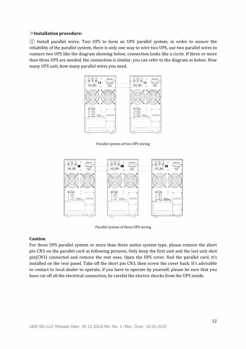
>Installation procedure: ① Install parallel wires. Two UPS to form an UPS parallel system, in order to ensure the reliability of the parallel system, there is only one way to wire two UPS, use two parallel wires to connect two UPS like the diagram showing below, connection looks like a circle. If three or more than three UPS are needed, the connection is similar, you can refer to the diagram as below. How many UPS unit, how many parallel wires you need.
Parallel system of two UPS wiring
Parallel system of three UPS wiring Caution For three UPS parallel system or more than three unites system type, please remove the short pin CN3 on the parallel card as following pictures, Only keep the first unit and the last unit shot pin(CN3) connected and remove the rest ones. Open the UPS cover, find the parallel card, it’s installed on the rear panel. Take off the short pin CN3, then screw the cover back. It’s advisable to contact to local dealer to operate, if you have to operate by yourself, please be sure that you have cut off all the electrical connection, be careful the electric shocks from the UPS inside.
DO NOT OPEN EXCEPTQUALIFIED TECHNICIAN
DO NOT OPEN EXCEPTQUALIFIED TECHNICIAN
USBEP
O
RS2
32
PARALLEL PORT
INTELLIGENT SLOT
BAT_NTC
ON
USBEP
O
RS2
32
PARALLEL PORT
INTELLIGENT SLOT
BAT_NTC
ON
USB
INTELLIGENT SLOT
PARALLEL PORT
EPO
RS2
32
BAT_NTC
INPUT BREAKER
ON OFF
WARNINGHIGH LEAKAGE CURRENTEARTH CONNECTION ESSENTIALBEFORE CONNECTING SUPPLY
USB
INTELLIGENT SLOT
PARALLEL PORT
EPO
RS2
32
BAT_NTC
INPUT BREAKER
ON OFF
WARNINGHIGH LEAKAGE CURRENTEARTH CONNECTION ESSENTIALBEFORE CONNECTING SUPPLY
HIGH LEAKAGE CURRENTEARTH CONNECTION ESSENTIALBEFORE CONNECTING SUPPLY
USBEP
O
RS23
2
PARALLEL PORT
INTELLIGENT SLOT
BAT_NTC
USBEP
O
RS23
2
PARALLEL PORT
INTELLIGENT SLOT
BAT_NTC
USBEP
O
RS2
32
PARALLEL PORT
INTELLIGENT SLOT
BAT_NTC
USB
INTELLIGENT SLOT
PARALLEL PORT
EPO
RS2
32
BAT_NTC
INPUT BREAKER
ON OFF
WARNINGHIGH LEAKAGE CURRENTEARTH CONNECTION ESSENTIALBEFORE CONNECTING SUPPLY
USB
INTELLIGENT SLOT
PARALLEL PORT
EPO
RS2
32
BAT_NTC
INPUT BREAKER
ON OFF
WARNINGHIGH LEAKAGE CURRENTEARTH CONNECTION ESSENTIALBEFORE CONNECTING SUPPLY
USB
INTELLIGENT SLOT
PARALLEL PORT
EPO
RS2
32
BAT_NTC
INPUT BREAKER
ON OFF
WARNINGHIGH LEAKAGE CURRENTEARTH CONNECTION ESSENTIALBEFORE CONNECTING SUPPLY
DO NOT OPEN EXCEPTQUALIFIED TECHNICIAN
DO NOT OPEN EXCEPTQUALIFIED TECHNICIAN
DO NOT OPEN EXCEPTQUALIFIED TECHNICIAN

13 UDD-SD-112/ Release Date: 25.12.2014/Rev No: 1 /Rev. Date: 18.05.2015
6KVA &10KVA Parallel Card 15KVA &20KVA Parallel Card
②Connect output cables of all UPS together to a common terminal block. ③Connect input cables of all UPS together to one common utility power terminal block. Input common termi nal bl ock
Uti l i ty power suppl y
Output common termi nal bl ock
Load Load Load Load . . . Parallel UPS system view
Short Pin
Parallel
Parallel Card

14 UDD-SD-112/ Release Date: 25.12.2014/Rev No: 1 /Rev. Date: 18.05.2015
Wiring diagram for two UPS parallel system
Wiring diagram for thee UPS parallel system ④ If the UPS is the standard type, each UPS has batteries inside already. If the UPS is the long-run type, each UPS should be equipped a individual battery pack. ⑤ After installation, check all the wiring carefully, be sure to con irm correct, then can operate the system. 3.3.2 Parallel System Operation and Maintenance General operation of parallel system, please refer to the operation instruction of single UPS. Before starting the system, need to set up different ID for each UPS, specific settings please refer to the instruction of ID setting which is given in single UPS panel function setting. >Turn on the parallel system
Start the system with mains power: After inputting the mains power,turn on any one UPS of system, others will start by themself at same time. All UPS will enter into Line mode. Start the system without mains power: Make sure the battery pack is connected well and the breaker is in “ON” position. There are two ways to start the UPS parallel system without utility power supply: A: Press the key on each UPS, make each LCD of each UPS light up, then turn on any one UPS of system, others will start by themself at same time. All UPS will enter into BAT mode. B: Turn on UPS one by one.
INPUT BAT1 BAT2OUTPUT
R S T N L N BAT+ BAT- R S T N L N BAT+ BAT-
INPUT BAT1 BAT2
R S T N L N BAT+ BAT- R S T N L N BAT+ BAT-
BAT3OUTPUT
R S T N L N BAT+ BAT-

15 UDD-SD-112/ Release Date: 25.12.2014/Rev No: 1 /Rev. Date: 18.05.2015
>Turn off the parallel system Hold on the OFF KEY of any one UPS of system for more than 4 seconds, it would turn off the whole parallel system. Hold on the OFF KEY of any one UPS of system for more than 1 second(less than 4 seconds), it would turn off single UPS you choose, of course if you need to turn on it again or turn on any other single UPS of the system, just press ON KEY of that UPS to start it.
>Parallel system maintenance
Parallel system maintenance please follow the maintenance of single UPS. If one UPS of parallel system is malfunctioning, first of all, turn off the malfunctioning UPS, then cut off the input power to the faulty UPS and disconnect the output of faulty UPS to the parallel system, make sure that there is no electrical connection with malfunctioning UPS, after all of those, it’s safe to do operation. 3.4 External Battery Connection Procedure for Long Back up Type
For different UPS type, users are instructed to configure different battery voltage as below sheet. More or less units are forbidden, or else something abnormal or faulty will appear. Type
Battery Quantity (unit)
Battery Voltage (volt) 6KVA 16/20 192V/240V 10KVA 16/20 192V/240V 15KVA 16/20 192V/240V 20KVA 16/20 192V/240V
NOTE There are two battery pack options for UPS, 16 units and 20 units. Users can choose the different battery pack voltage in accordance with different requirements. The default units of batteries to UPS is 16, and users can not connect 16 batteries to UPS if the UPS should be connected 20 units. Please strictly follow the procedure of batteries connection, or will get electric shocks. 1. Set the battery switch at ‘OFF’ position, then install batteries in series. 2. Connecting the cables to batteries firstly, or you may get electric shocks if you connect the cables to UPS firstly. You’d better connect the red cable to battery positive pole ‘+’, black to negative pole ‘-’, so that it would be much easier to distinguish. 3. Select proper cables to connect the batteries and UPS is very important, and there should be a switch connected between the battery pack and UPS. 4. Finally, without any load, set on the battery switch which is connected between the UPS and the battery pack, so that UPS can get connected to batteries, then switch in the mains power, after doing all of those, the batteries will be charged by the UPS automatically.

16 UDD-SD-112/ Release Date: 25.12.2014/Rev No: 1 /Rev. Date: 18.05.2015
3.5 Network Functions
3.5.1 Communication Port Users could monitor the UPS system through the communication port such as standard RS232 port and standard USB port with computer. With a communication wire to connect UPS and computer, could simply achieve UPS management. ☆RS232 port: Foot 1 2 3 4 5 6 7 8 9 Explanation empty send receive empty ground empty empty empty empty
☆USB port: Foot 1 2 3 4 Explanation +5V date+ date- GND

17 UDD-SD-112/ Release Date: 25.12.2014/Rev No: 1 /Rev. Date: 18.05.2015
3.5.2 EPO Port EPO is short for Emergency Power Off, EPO port is on rear panel of UPS, it’s green, in some emergent cases, users could cut off the output of UPS immediately by operating EPO port. Wiring diagram as below:
Normally, pin1 and pin2 are connected so that the machine can be working normally. When some emergencies happen, and when users do have to cut off the output, just need to disconnect the connection between pin1 and pin2, or there is a anther useful simple way is pulling it out. 3.5.2 Intelligent Card (Option) This series High frequency online UPS supply a intelligent slot on rear panel, it’s for SNMP card, dry contact and USB card, users could insert any type intelligent card from those three into it to monitor and manager the UPS. You don’t have to turn off the UPS when you install the intelligent card. Procedure as following: Fist of all, remove the intelligent slot cover; Then insert the intelligent card(SNMP card, dry contact or USB card); Last, screw the intelligent card back. > SNMP card (option) SNMP card on UPS is compatible with the most software, hardware and network operating system, it is a network management of UPS, with this function, UPS can login on internet , which can supply information of UPS status and input power, and even possible to control UPS via net management system. > Dry contact card (option) Insert the dry contact card into the intelligent slot, it’s another type function of intelligent monitoring.

UDD-SD-
> RS485RS485 cRS485.
All abov
3.6 MaUPS witswitch cWhen yo Open t Set the Now y After f cover b Complet
-112/ Releas
5 card (optcard is also
ve, for more intenanceth maintenacover you caou need to mthe maintene switch at “you can mainfinishing theback. te all the ste
se Date: 25.1
ion) designed f
informatione Switch (Oance switch(an see a maimaintain or nance bypass“BYPASS” pontain or repae maintenaneps above, y
12.2014/Rev
for this seri
n, please conOption) (option) canntenance swrepair the Us switch covosition; air the UPS;nce operatio
ou are done
No: 1 /Rev.
FootPIN1PIN2PIN3PIN4PIN5PIN6PIN7PIN8PIN9
es UPS, A(+
ntact to the ln be maintawitch if the UUPS online, fver, UPS will on, set the s
e the mainte
Date: 18.05
Defin1 ON:2 ON:3 Groun4 Remo5 Comm6 ON:7 ON:8 ON:OFF:9 ON:
+) and B(-)
local dealerined online.UPS has thisfollow the prl transfer to switch backnance.
5.2015
ition UPS is malfuAlarm(sysnd ote shutdowmon Bypass modBattery lowInverter mo:Bypass moNo AC powe
on the righ
. . Open the ms function. rocedure asBYPASS mo
k to “UPS” p
unctioning stem failurewn
de w ode; ode er in ht are the o
maintenancs below: ode automatosition, and
18
)
output of
e bypass tically; d put the

UDD-SD-
3.7 BatThere adefault batteriethe UPSboard an
B1620
NOTE For long -112/ Releas
ttery Pack re two optioquantity is es. When use case and find charger b
Battery grou units batter units batterg-run type U
se Date: 25.1
Selecting ons of batte16 units, bers want tond the contboard.
Controup ries A. RemB. Insries A. RemB. Ins
UPS, there ar
12.2014/Rev
ery group qubut this ser apply 20 utrol board an
ol board move the shert the shormove the shert the shorre two charg
Short p
No: 1 /Rev.
uantity for uries UPS arunits batterind the charg
Ohort pin(J16)rt pin(middlhort pin(midrt pin(J16) o
gers, users h
pin
Date: 18.05
users to chore also allowes group foger, then op
ChargerOperation) off the cone of CN7) ofddle of CN7) of the controhave to oper
5.2015
oose, 16 uniwed to conr this seriesperate the sh
r board ntrol board; f the chargerof the chargol board. rate two cha
ts and 20 unnect with s UPS, needhort pins on
r board. ger board; arger board.
Short
19
nits. The 20 units d to open n control

20 UDD-SD-112/ Release Date: 25.12.2014/Rev No: 1 /Rev. Date: 18.05.2015
4 PANEL FUNCTION and OPERATION The operation is simple, operators only need to read the manual and follow the operation instructions listed in this manual without any special training. 4.1 Keys Function
※ ON KEY ( + ) Press and hold the two keys for more than half a second to turn on the UPS. ※ OFF KEY ( + ) Press and hold the two keys for more than half a second to turn off the UPS. ※ TEST/MUTE KEY ( + ) Press and hold the two keys for more than 1 second in Line mode or ECO mode or CUCF mode: UPS runs the self-test function. Press and hold the two keys for more than 1 second in battery mode: UPS runs the mute function. ※ INQUIRING KEY ( , ) Non-function setting mode: Press and hold or for more than half a second (less than 2 seconds): display the items orderly. Press and hold for more than 2 seconds: Circularly and orderly display the items every 2 seconds, when press and hold the key for some time again, it will turn to output status. Function setting mode: Press and hold the key or for more than half a second (less than 2 seconds): Select the set option.

UDD-SD-
※ FUNCNon-funPress anFunctionPress ansetting oPress an4.2 LED
Numbe① ② ③ ④ PS: LED 4.3 LCDLCD disp
-112/ Releas
CTION SETTnction settinnd hold the kn setting mond hold the koption. nd hold the kD Function
er LEInverteBatteryBypassWarnindisplay det
D Display Fplays as foll
se Date: 25.1
TING KEY ng mode: key for morode: key for morkey for mor
n
D er LED Invmoy LED Bats LED Bypng LED Waallotail in differeFunction owing figur
12.2014/Rev
e than 2 sece than half ae than 2 sec
verter greenode or BAT mttery yellowpass yellow arning red Lowed time, ient mode is e.
No: 1 /Rev.
conds: Functa second (leconds: exit fr
LED is on: Umode. w LED is on: BLED is on: BED is on: UPinverter faullisted at the
Date: 18.05
tion setting ss than 2 serom this fun
ExplaUPS is normBattery modBypass modPS fault. For lt, BUS fault
e back.
5.2015
interface. conds): Ent
nction settin
anation mally powerede. e or ECO moexample: Ot, over tempe
er the functng interface.
ed by Line mode, etc. verload beyerature faul
Digital dis
Working mode displ
Icon displa
21
tion
mode or ECOyond the lt, etc
play area
ay
ay
O

22 UDD-SD-112/ Release Date: 25.12.2014/Rev No: 1 /Rev. Date: 18.05.2015
※ Icon display area:
A. The top diagram is for load and battery capacity indication, each grid of which represents 25%. When UPS is over load, the load light will blink the same as the battery light blink when the capacity of battery get low or battery disconnected. B. The fan icon is for fan working indication; when fan normally runs, the icon will display rotation; if the fan is not connected or faulty, the icon blinks; C. Press the mute button under the battery mode, buzzer icon will blink; it will disappear in other cases. D. Fault icon will be on when UPS is in fault mode, otherwise it will not. ※ Digital display area: A. Under none setting mode, it will display UPS output information when UPS normally runs in AC mode; other information like input, battery, load and temperature will be showed after pressing the inquiring key; Fault code will be told in fault mode. B. Under setting mode, users could adjust different output voltage, activate ECO mode, activate CUCF mode, select an ID number and so on by operating function setting key and inquiring keys. ※ Mode display area: A. This area will display the power capacity of the machine after starting the UPS within 20 seconds. B. After over 20 seconds, this area will display the working mode of the machine. Such as STDBY(standby Mode), BYPASS(Bypass Mode), LINE(AC Mode), BAT(Battery Mode), BATT(Battery Self Test Mode ), ECO(Economic mode), SHUTDN(Shutdown mode), CUCF(Constant Voltage and Constant Frequency Mode).

23 UDD-SD-112/ Release Date: 25.12.2014/Rev No: 1 /Rev. Date: 18.05.2015
4.4 Single UPS Turn On/Off Operation
4.4.1 Turn On Operation
> Turn on the UPS on line mode 1. Once mains power is plugged in, the UPS will charge the battery, at the moment, LCD shows that the output voltage is 0, which means UPS has no output as default condition. If it is expected to have output of bypass, you can set the BPS “ON” by LCD setting menu. 2. Press and hold the ON key for more than half a second to start the UPS, then it will start the inverter. 3. Once started, the UPS will perform a self-test function, and LED will light and go off circularly and orderly. When self-test finishes, it will come to online mode, the corresponding LED lights, UPS is working in line mode. Turn on the UPS by DC without mains power 1. When main power is disconnected, press and hold the ON key for more than half a second to start UPS. 2. The operation of UPS in the process of start is almost the same as that when mains power is on. After the self-test finishes, the corresponding LED lights and UPS are working in battery mode. 4.4.2 Turn Off Operation
> Turn off the UPS in line mode 1. Press and hold the OFF key for more than half a second to turn off the UPS and inverter. 2. After UPS shutting down, LED goes out and there is no output. If output is needed, you can set BPS “ON” on LCD setting menu. > Turn off the UPS in DC mode without mains power 1. Press and hold the OFF key for more than half a second to turn off the UPS. 2. When turning off the UPS, it will do self-test first. LED lights go out circularly and orderly until there is no display on the panel.

24 UDD-SD-112/ Release Date: 25.12.2014/Rev No: 1 /Rev. Date: 18.05.2015
4.5 Single UPS Self-Test/Mute Test Operation
1. When UPS is in LINE Mode, press and hold the self-test/mute key for more than 1 second, LED light will go off circularly and orderly. UPS comes to self-test mode and tests its status. It will exit automatically after finishing test. 2. When UPS is in BAT Mode, press and hold the self-test/mute key for more than 1 second, the buzzer stops beeping. If you press and hold the self-test/mute key for one more second, it will restart to beep again. 4.6 Single UPS Panel Function Setting
UPS has setting function. It can run the setting in any mode. After setting, it will become effective at once when meets some standards. The set information can be saved only when the battery connected and normally turning off the UPS. 4.6.1 ECO Mode Setting
1. Enter the setting interface. Press and hold the function setting key for more than 2 seconds, then come to setting interface, press and hold the inquiring key ( , ) for more than half a second(less than 2 seconds), select the function setting, choose output voltage setting interface, at the moment, the letters “ECO” will flash. 2. Enter the ECO setting interface. Press and hold the function setting key for more than half a second(less than 2 seconds), then come to setting interface of ECO, at this time, the letters “ECO” will not flash any more. The “ON” (or OFF) will flash. Press and hold the inquiring key ( , ) for more than half a second (less than 2 seconds) to determine whether the ECO function is used or not. If used, the corresponding word is “ON”, if not, the word is “OFF”. It can be determined by yourself. 3. Confirm the ECO selecting interface. After selecting ON or OFF, press and hold the function setting key for more than half a second (less than 2 seconds). Now, the ECO setting function is completed and the “ON” or “OFF” will light without flash. 4. Exit from the setting interface. Press and hold function setting key for more than 2 seconds, exit from the setting interface and return to main interface.

25 UDD-SD-112/ Release Date: 25.12.2014/Rev No: 1 /Rev. Date: 18.05.2015
4.6.2 Input Methods Setting
1. Enter the setting interface. Press and hold the function setting key for more than 2 seconds, then come to setting interface, press and hold the inquiring key ( , ) for more than half a second(less than 2 seconds), select the function setting, choose output voltage setting interface, at the moment, the letters “IPP” will flash. 2. Enter the IPP setting interface. Press and hold the function setting key for more than half a second(less than 2 seconds), then come to setting interface of IPP, at this time, the letters “IPP” will not flash any more, the numerical value next to the IPP will flash. Press and hold the inquiring key ( , ) for more than half a second (less than 2 seconds) to select the numerical value. There are two Input methods, the value ‘1’ means single phase input, the value ‘3’ means three phase input. The default input method is single phase. 3. Confirm the IPP selecting interface. After selecting input method, press and hold the function setting key for more than half a second (less than 2 seconds). Now, the IPP setting function is completed and the value next to IPP will light without flash. 4. Exit from the setting interface. Press and hold function setting key for more than 2 seconds, exit from the setting interface and return to main interface. 4.6.3 Output Voltage Setting
1. Enter the setting interface. Press and hold the function setting key for more than 2 seconds, then come to setting interface, press and hold the inquiring key ( , ) for more than half a second(less than 2 seconds), select the function setting, choose output voltage setting interface, at the moment, the letters “OPU” will flash. 2. Enter the output voltage setting interface. Press and hold the function setting key for more than half a second(less than 2 seconds), then come to setting interface of output voltage OPU, at this time, the letters “OPU” will not flash any more. The numerical value next to the OPU will flash. Press and hold the inquiring key ( , ) for more than half a second (less than 2 seconds), select the numerical value in accordance with “OPU” function. The provided

26 UDD-SD-112/ Release Date: 25.12.2014/Rev No: 1 /Rev. Date: 18.05.2015
voltages are 208V, 220V, 230V, 240V, you can choose anyone by yourself (The default value is 220V). 3. Confirm the output voltage setting interface. After selecting numerical value, press and hold the function setting for more than half a second (less than 2 seconds). Now, the OPU setting function is completed and the numerical value will light without flash. 4. Exit from the setting interface. Press and hold function setting key for more than half a second (less than 2 seconds), exit from the setting interface and return to main interface.
4.6.4 Low Battery Voltage Shutdown Point Setting
1. Enter the setting interface. Press and hold the function setting key for more than 2 seconds, then come to setting interface, Press and hold the inquiring key ( , ) for more than half a second(less than 2 seconds), select the function setting, choose battery voltage setting interface, at the moment, the letters “bat” will flash. 2. Enter the battery voltage selecting interface. Press and hold the function setting key for more than half a second(less than 2 seconds), then come to setting interface of battery voltage, this time, the numerical value will flash. Press and hold the inquiring key ( , ) for more than half a second (less than 2 seconds), select the numerical value in accordance with “battery” function. The provided voltages are 10V, 10.2V, 10.5V, numbers stand for the voltage of each battery, you can choose anyone by yourself (The default is 10V), anyone has been chosen, under BAT mode, UPS will shutdown when its battery voltage achieve the voltage you chose. 3. Confirm the battery voltage selecting interface. After selecting numerical value, press and hold the function setting , for more than half a second (less than 2 seconds). Now, the battery setting function is completed and the numerical value will light without flash. 4. Exit from the setting interface. Press and hold function setting key for more than half a second (less than 2 seconds), exit from the setting interface and return to main interface.

27 UDD-SD-112/ Release Date: 25.12.2014/Rev No: 1 /Rev. Date: 18.05.2015
4.6.5 Frequency Converter Mode Setting
1. CUCF mode only can be set in STDBY mode. In STDBY mode, enter the setting interface. Press and hold the function setting key for more than 2 seconds, then come to setting interface, Press and hold the inquiring key ( , ) for more than half a second(less than 2 seconds), select the function setting, choose battery voltage setting interface, at the moment, the letters “CF” will flash. 2. Enter the CF setting interface. Press and hold the function setting key for more than half a second(less than 2 seconds), then come to setting interface of CF, at this time, the letters “CF” will not flash any more. The “ON” (or OFF) will flash. Press and hold the inquiring key ( ,
) for more than half a second (less than 2 seconds) to determine whether the CF function is used or not. If used, the corresponding word is “ON”, if not, the word is “OFF”. It can be determined by yourself. 3. Confirm the CF selecting interface. After selecting ON or OFF, press and hold the function setting key for more than half a second (less than 2 seconds). Now, the CF setting function is completed and the “ON” or “OFF” will light without flash. 4. Exit from the setting interface. Press and hold function setting key for more than 2 seconds, exit from the setting interface and return to main interface. 5. After setting CF at “ON”, UPS would be back in STDBY Mode. The default value of CF is OFF.

28 UDD-SD-112/ Release Date: 25.12.2014/Rev No: 1 /Rev. Date: 18.05.2015
4.6.6 Output Frequency Setting in CUCF Mode
1. Output frequency only can be set when CUCF mode is ON. 2. In STDBY mode, enter the setting interface. Press and hold the function setting key for more than 2 seconds, then come to setting interface, Press and hold the inquiring key ( , ) for more than half a second(less than 2 seconds), select the function setting, choose battery voltage setting interface, at the moment, the letters “OPF” will flash. 3. Enter the OPF setting interface. Press and hold the function setting key for more than half a second(less than 2 seconds), then come to setting interface of OPF, at this time, the letters “OPF” will not flash any more. The “OFF” (or 50HZ, 60HZ) will flash. Press and hold the inquiring key ( , ) for more than half a second (less than 2 seconds) to determine whether the CF function is used or not. If used, select 50HZ or 60HZ according to you. It is determined by yourself, the default value is 50HZ. 4. Confirm the OPF selecting interface. After selecting 50HZ or 60HZ, press and hold the function setting key for more than half a second (less than 2 seconds). Now, the OPF setting function is completed and the “50HZ” or “60HZ” will light without flash. 5. Exit from the setting interface. Press and hold function setting key for more than 2 seconds, exit from the setting interface and return to main interface.
4.6.6 ID Setting
1. Enter the setting interface. Press and hold the function setting key for more than 2 seconds, then come to setting interface, press and hold the inquiring key ( , ) for more than half a second(less than 2 seconds), select the function setting, choose output voltage setting interface, at the moment, the letters “Id” will flash. 2. Enter the output voltage setting interface. Press and hold the function setting key for more than half a second(less than 2 seconds), then come to setting interface of ID, at this time, the letters “Id” will not flash any more. The numerical value next to the “Id” will flash. Press and hold the inquiring key ( , ) for more than half a second (less than 2

UDD-SD-
secon choo3. Conf the fu funct4. Exit secon NOTE ID only
4.7 Par
Press aninquire The disp Outputshows, t
Load: Dload. Fo-112/ Releas
nds), select se anyone bfirm the outunction setttion is compfrom the send (less thancan be set b
rameters I
nd hold the iabout itemsplayed items:Display ththe output v
Display the nr example, ase Date: 25.1
the numericby yourself (tput voltage ting for pleted and thtting interfan 2 secondsbefore doing
Inquiring O
inquiring kes. The inquirs on LCD scrhe output vovoltage is 22
numerical vaas the follow12.2014/Rev
cal value. Th(The defaultsetting intemore than hhe numericaace. Press an), exit from g parallel ope
Operation
ey orred items inreen are shooltage and o20V, the outp
alue of the awing graphic
No: 1 /Rev.
he provided t value is 1).erface. After half a seconal value will nd hold functhe setting ieration.
for more clude input,owed as follo
utput frequput frequenc
ctive powercs shows: thDate: 18.05
ID numbersselecting nud (less thanlight withouction settinginterface an
than half a s, battery, ouowing: ency of the Ucy is 50Hz.
r (WATT) anhe WATT of t5.2015
s are 1, 2, 3, umerical val 2 seconds)ut flash. g key fornd return to
second(less utput, load anUPS. As the
nd apparent the load is 9
4, 5, 6, 7, 8, lue, press an. Now, the IDr more thanmain interfa
than 2 second temperafollowing gr
power (VA)9KW, VA is 129
you can nd hold D setting n half a ace.
onds) to ture. raphic
) of the 10KVA

UDD-SD-
(when dVA).
Temperfollowin
Input: Dvoltage
Batterygraphicsbattery
-112/ Releas
disconnect lo
rature: Disng graphics s
Display the vis 220V, inp
y: Display ths shows: theis approxim
se Date: 25.1
oad, it is a n
splay the mshows: the m
voltage and put frequenc
e voltage ane battery volmately recko
12.2014/Rev
ormal phen
maximum temaximum te
frequency ocy is 50Hz.
nd capacity oltage is 192Vned accordi
No: 1 /Rev.
omenon to s
emperature emperature
of the input.
of the batterV, the capacing to the ba
Date: 18.05
show a sma
of the comis 40℃.
As the follo
ry (determincity of batterattery voltag
5.2015
all numerical
mponents i
owing graph
ned by type)ry is 100% (ge).
l value of W
in the UPS
ics shows: t
). As the foll(the capacity
30
WATT and
. As the
the input
lowing y of

31 UDD-SD-112/ Release Date: 25.12.2014/Rev No: 1 /Rev. Date: 18.05.2015
Press and hold the inquiring key for more than 2 seconds, LCD begins to display the items circularly and orderly which transfer to another every 2 seconds. Press and hold the key for some time again within 30s, it will return to output status. 5 WORKING MODE INTRODUCTION 5.1 Bypass Mode
LED indications on front panel in bypass mode are as following: Bypass yellow LED is on, the buzzer beeps once every 2 minutes. The warning red LED is on when beeping, what LCD displays depending on the exact load and battery capacity. Turn to bypass mode under the following two conditions: 1. Turn off the UPS line mode while start the bypass output. 2. Overload in line mode. NOTE When UPS is working in bypass mode, it has no back up function. 5.2 Line Mode
LED indications on front panel in line mode or CUCF mode are as following: The inverter green LED is on.
When input AC mains correspond to the working conditions, UPS will work in line mode. 5.3 Battery Mode
LED indications on front panel in battery mode are as following: both the inverter green LED and battery yellow LED is on, the buzzer beeps once every 4 seconds. The warning red LED will be on while beeping.

UDD-SD-
When th 5.4 ECO
LED indbypass y When thUPS willminute bNote: Onmode) f 5.4 Fau
LED inddisplay
Fault moWhen UUPS cuts-112/ Releas
he mains poO Mode
dications on yellow LED
he input mail works in Ebut stays in n ECO modefrom ECO moult Mode
dications on fault code a
ode (LCD inUPS has faults off the outse Date: 25.1
wer is low o
front panel are on.
ins meets thCO mode. Ifinverter inpe, when the Uode, 15ms in
front panel nd related i
terface on wted. The wartput and LCD12.2014/Rev
or unstable,
in ECO mod
he input ranf input AC mput range, UUPS switchenterrupt pro
in Fault mocon.
which the faurning LED isD display fau
No: 1 /Rev.
UPS will tur
de are as foll
ge of the ECmains exceedUPS will wores to Inverteobably be ha
de are as fo
ult code disps on and the ult codes. AtDate: 18.05
rn to battery
lowing: both
CO mode andd the range ork in AC inveer mode (incappened.
llowing: wa
play) buzzer beept the momen5.2015
y mode at on
h the inverte
d the ECO fuof ECO severerting modecluding Line
rning red LE
ps. UPS willnt, you can p
nce.
er green LED
unction is onral times wi automaticae mode and B
ED is on and
turn to faulpress the mu 32
D and
n, the thin one ally. BAT
d LCD
lt mode. ute key

33 UDD-SD-112/ Release Date: 25.12.2014/Rev No: 1 /Rev. Date: 18.05.2015
to make the buzzer stop beeping temporarily to wait for maintenance. You can also press the OFF key to shut down the UPS when confirmed that there is no serious fault.
6 THE WARNING CODE LIST OF THE LED LIGHT and DISPLAY PANEL Appendix 1: The table of the fault code Fault code Fault type Bypass output Note 0、1、2、3、4 Bus high Yes 5、6、7、8、9 Bus low Yes 10、11、12、13、14 Bus unbalance Yes 15、16、17、18、19 Bus soft start fail Yes 20、21、22、23、24 Inverter soft start fail Yes 25、26、27、28、29 Inverter high Yes 30、31、32、33、34 Inverter low Yes 35、36、37、38、39 Bus discharge fail Yes 40、41、42、43、44 Over heat Yes 45、46、47、48、49 OP(inverter) shorted No 50、51、52、53、54 Overload Yes 55、56、57、58、59 Negative output power Yes 60、61、62、63、64 Shutdown fault Yes 65、66、67、68、69 BUS shorted Yes 75、76、77、78、79 Communication fault Yes 80、81、82、83、84 Relay fault Yes 85、86、87、88、89 AC input SCR fault Yes unused 90、91、92、93、94 CAN fault Yes 95、96、97、98、99 ID conflict Yes 100、101、102、103、104 Incompatible type No c

34 UDD-SD-112/ Release Date: 25.12.2014/Rev No: 1 /Rev. Date: 18.05.2015
Appendix 2: Table for working status
S/N Working status LED on Front panel Alarm beep Note Normal Battery Bypass Fault 1 Inverter mode (mains power) Mains power voltage ● N Mains power high/low voltage protection, switch to battery mode ● ● ★ One beep / 4 sec
2 Battery mode Battery voltage - normal ● ● ★ One beep / 4 sec Warning for abnormal voltage of battery ● ★
★ One beep / sec 3 Bypass mode
Mains power – normal(under Bypass) ● ★ One beep / 2 mins Mains power – high voltage warning (under Bypass) ● ★ One beep / 4 sec Mains power – low voltage warning (under Bypass) ● ★ One beep / 4 sec
4 Warning for battery disconnected Bypass mode ● ★ One beep / 4 sec Inverter mode ● ★ One beep / 4 sec Power on / Switch on 6 beeps 5 Output overload protection
Warning for mains power overload ● ★ 2 beeps / sec Protect operation for mains power mode overload ● ● Long beep Warning for battery ● ● ★ 2 beeps / sec

35 UDD-SD-112/ Release Date: 25.12.2014/Rev No: 1 /Rev. Date: 18.05.2015
overload Protect operation for battery mode overload ● ● ● Long beep 6 Warning for bypass mode overload ● ★ One beep / 2 sec 7 Fans fault(fan icon) ▲ ▲ ▲ ★ One beep / 2 sec 8 Faults mode ● Long beep
● LED indicator lights long time ★ LED indicator flicker ▲ LED indicator status depends on other conditions Note: End user need to provide below information when require to maintain the UPS. UPS Model No. & Serial No. Date of fault occurrence. Fault detail (LED status, noise, AC power situation, load capacity, for long back up type, battery capacity configuration is also necessary.)

FPiFpiFpiFpi
UDD-SD-
7 TRWhen th
Explicit
TrouFault LED onPersistentlyis 00-14 Fault LED onpersistently is15-24 Fault LED onpersistently is 25-39 Fault LED onpersistently is 40-44
-112/ Releas
ROUBLhe system ru
t Troublesh
uble indicatn, audible buy alarm, the fn, audible bualarm, the fn, audible bualarm, the fn, audible bualarm, the f
se Date: 25.1
LE SHOuns in failur
hoot Introd
tion uzzer fault code uzzer fault code uzzer fault code uzzer fault code
12.2014/Rev
OOTINGe mode, the
uction Shee
Failu
Bus bar voSoft start Inverter vOver tempinside
Fault c
No: 1 /Rev.
G LCD will sh
et
ure point
oltage faultfault
voltage faultperature
code
Date: 18.05
how as below
Please the supPlease especiacontactPlease Please overloaobstrutemperLeave acoolingplease
5.2015
w:
So
test the buspplier. check the soally the soft t the suppliecontact the make sure tad, and the fcted, as welrature is notalone the UPg, and restarcontact the
Fault icon
olution
s bar voltageoft start up start resistaer directly. supplier.
the UPS didnfan vent wasl as the indot high. PS 10 minutrt it. If failursupplier. 36
e or contact circuit, ance or
n’t get s not oor tes for re remains,

37 UDD-SD-112/ Release Date: 25.12.2014/Rev No: 1 /Rev. Date: 18.05.2015
Fault LED on, audible buzzer Persistently alarm, the fault code is 45-49 Output short-circuited Turn of the UPS and disconnect all the load, make sure there no any fault or internal short circuit of the load. And then restart the UPS, if failure still, please contact the supplier. Fault LED on, audible buzzer persistently alarm, the fault code is 50-54 Over load
Please check the load level and disconnect the noncritical devices, recount the total capacity of your load and reduce the load to the UPS. Please check whether the load device has fault or not. Fault LED on, audible buzzer persistently alarm, the fault code is 55-59 Negative output power Please contact the supplier. Fault LED on, audible buzzer persistently alarm, the fault code is 60-64 Power fault Please Check whether the input & output power normal or not, contact the supplier if it is abnormal. Fault LED on, audible buzzer persistently alarm, the fault code is 65-69 BUS short-circuited Please contact the supplier. Fault LED on, audible buzzer Persistently alarm, fan icon in the LCD flickers Fan fault Please check whether the fans connect well, is the fan plugged and is the fan broken? If all above condition is OK, please contact the supplier. UPS fail to start when operate “On” key
Pressing time too short Please press the power key more than 2 seconds to start the UPS. The input connection is not ready or UPS internal battery disconnect Please connect the input well, if the battery voltage is too low, please disconnect the input and start the UPS with no-load. UPS internal system fault Please contact the supplier.
Back up time become short Battery undercharge Please keep the UPS battery recharging more than 3 hours UPS overload Please check the load level and disconnect the noncritical devices, Battery maturing, capacity descend Please change new battery, contact your supplier to get the new battery and spare parts.
UPS doesn’t have any power go through even main power on UPS input breaker disconnects Please reset the circuit breaker by manual. Input fuse broken or input method is inconsistent with the Please check the fuse and IPP setting, and contact the supplier.

38 UDD-SD-112/ Release Date: 25.12.2014/Rev No: 1 /Rev. Date: 18.05.2015
IPP setting Attention: When the output is short-circuited, the action of the protection of the UPS will show up. Before turning off the UPS, please make sure to disconnect the entire load and cut off the AC mains power supply, otherwise will make the AC input short-circuit. Appendix 1: EMC Level The series product is designed to meet the below standard. EMS
IEC61000-4-2(ESD) Level 4 IEC61000-4-3(RS) Level 3 IEC61000-4-4(EFT) Level 4 IEC61000-4-5(Surge) Level 4 EMI GB9254-1998/IEC 62040-2 Class B
Appendix 2: Symbol instructions: Symbols and significations Symbol Significations Symbol Significations Caution Protect grounding Danger! High Voltage! Alarm cancel Turn on Overload Turn off Battery inspection Standby or Shutdown Repeat AC Display screen repeat key DC Battery

39 UDD-SD-112/ Release Date: 25.12.2014/Rev No: 1 /Rev. Date: 18.05.2015
Appendix 3: Specification Sheet
MODEL SE906II SE9010II SE9015II SE9020IICapacity 6KVA/5.4KW 10KVA/9KW 15KVA/13.5KW 20KVA/18KWINPUT Rated Voltage 3/1: 360V/365V/380V/400V/415VAC; 1/1: 208V/210V/220V/230V/240VAC. (Set up by LCD display) Voltage Range 3/1: Half load (190-520)±5VAC, Full load (277-520)±5VAC;1/1: Half load (110-300)±5VAC, Full load (160-300)±5VAC. Frequency 40-70Hz±0.5% (Auto sensing) Power Factor 3/1: ≥0.95;1/1: ≥0.99.
BYPASS Voltage Range 160V-Rated output voltage+32V Frequency 50/60Hz±5HzOUTPUT Voltage 208V/210V/220V/230V/240Vac Setting available via LCD Voltage Regulation ±1% Frequency Synchronized with utility on AC mode; 50/60±0.1Hz on battery mode Waveform Pure sine waveCrest Factor 3:1Harmonic Distortion ≤2%(Linear load); ≤5%(Non-linear load) Transfer Time AC mode to battery mode: 0ms Inverter mode to bypass mode: 0ms Overload Capability 105%-125%: Transfer to bypass after 3mins; 125%-150%: Transfer to bypass after 30s; >150%: Transfer to bypass after 100ms
EFFICIENCY AC Mode ≥93%Battery Mode ≥92%ECO Mode ≥98%BATTERY DC Voltage 192V/240VDCInbuilt Battery of Standard Model 16*7AH 16*9AH NO Charge Current Standard Model 1A Long Time Model 7A

40 UDD-SD-112/ Release Date: 25.12.2014/Rev No: 1 /Rev. Date: 18.05.2015
Typical Recharge Time 8 hours recover to 90% capacity ALARM Utility Failure Beep/4sBattery Low Beep/1sOverload Beep Twice/1sUPS Fault Long Beep
ENVIRONMENT Humidity 20~90% RH @ 0~40℃(non-condensing) Noise Level ≤58dB (1m) ≤60dB (1m)MANAGEMENT Standard RS-232 and USB Supports Windows 98/2000/2003/XP/Vista/2008/7/8 Optional SNMP Power management from SNMP manager and web browser
PHYSICAL Dimension(mm) W*D*H 262×580×455(H), 262×580×732(S) 262×580×628(H) Packing Dimension(mm) W*D*H 355×682×615(H), 359×687×822(S) 359×687×717(H) Net Weight(kg) 25.0(H), 73.0(S) 25.5(H), 74.0(S) 38.5(H) 39.0(H) Gross Weight(kg) 28.5(H), 82.5(S) 29.0(H), 83.5(S) 47.0(H) 47.5(H)
Derate capacity to 70% in CUCF mode and to 90% when the output voltage is adjusted to 208Vac. 3/1 means three phase input and single phase output mode, 1/1 means single phase input and single phase output mode. S means standard model, H means long backup time model.

41 UDD-SD-112/ Release Date: 25.12.2014/Rev No: 1 /Rev. Date: 18.05.2015
8 GUARANTEE 8.1 Terms of Guarantee
Our products are under a two-year guarantee starting from the date of delivery against malfunctions resulting from production, material and workmanship faults. Malfunctions due to such type of faults will be removed without claiming any price of workmanship or spare parts to be replaced. Whether aforementioned malfunctions originate from usage faults or not are determined with a report to be issued by service stations, if there exists no service stations, by one of seller, dealer, agency, representative, importer or manufacturer or producer of those products respectively. Repair time of defective products is twenty business days at most. This period starts from the date when products are delivered to one of seller, dealer, agency, representative, importer or one of manufacturer or producer. Provided that products break down within the period of guarantee, the time passing during the repair process is added to the guarantee time. Provided that faults of products cannot be removed within ten business days, manufacturer-producer or importer is obliged to assign another product having similar features for the use of consumers until the faulty product has been repaired. Even though consumers exercise their repair rights, they can claim free replacement of products, refund or price discount at the rate of faultin the events;
That, besides, the product,as of the date when the product is delivered to the consumer, breaks down four times a year or six times within the guarantee period to be determined by the manufacturer-producer and/or importer at least, on the condition of being in guarantee period, such malfunctions perpetuate passing over; That maximum time required for the repair of products is exceeded; That repair of the malfunction is determined as impossible through a report to be issued by service station, if there exists no service station, one of seller, dealer, agency, representative, importer or manufacturer or producer of the company respectively.
The consumer is, on demand, obliged to submit guarantee certificate in terms of repairs or replacements within the scope of guarantee.

42 UDD-SD-112/ Release Date: 25.12.2014/Rev No: 1 /Rev. Date: 18.05.2015
It is essential that you definitely perform damage control over external packaging before receiving the products to be sent through freight. In the event of any damage, delivery person must be made to prepare a “damage determination record”. (For example; duringthe delivery process, the product has been checked and seen that is damaged.) After the damage determination record has been issued, we request you to inform the MAKELSAN head office of the case. Products to be received from freight by signature means that products have been received completely and without no damage. Repairs of plug-and-play products in the places where no service point is around are performed in the factory of MAKELSAN or the nearest service point according to the direction to be made by the MAKELSAN head office. Defective product is delivered by hand to the nearest service point or to the contracted freight company in its original packaging to be sent to the factory of MAKELSAN according to the direction to be made by the MAKELSAN head office. For malfunctions in the scope of guarantee, shipment fees are under the responsibility of MAKELSAN on the condition that products are delivered to the contracted freight company. The device must be sent as packed in its original packaging as long as it is not desired by the service. Original packaging of devices should be preserved in order to use them for shipment of devices in terms of repairs to occur. Otherwise, no responsibility is assumed with regards to any troubles to be experienced. All defective products to be delivered by hand or through freight are to meet the necessary shipment requirements. (Anti-static protective, bubble wrap or box etc.)It is essential that legible barcode serial number belonging to the product be on the product. Otherwise, it is not covered in the scope of the guarantee. It is essential that products to be sent through freight definitely be together with delivery note, and that serial/model/malfunction details be written on delivery note to be sent (for example, breakdown report form), and that packaging content match with the products specified in the delivery note. Otherwise, freight is not accepted. The use of theGuarantee Certificate, submitted together with products with MAKELSAN trademark,is permitted by the T.R. Ministry of Industry and Commerce and General Directorate of Protection of Competition with no……. in accordance with the law, with no. 4077, and the notification, with no. TRKGM-95/116-117, issued basing the aforementioned law. MAKELSAN acknowledges and undertakes to obey the liabilities determined by the laws and legislations.
8.2 Cases Not Covered by the Guarantee
Breakdowns resulting from the use of products contrary to the issues or the environment conditions (temperature, humidity etc.) specified in the user manual are not covered in the scope of guarantee.

43 UDD-SD-112/ Release Date: 25.12.2014/Rev No: 1 /Rev. Date: 18.05.2015
Damages and breakdowns resulting from the use of software, hardware, interface, accessories or consumables apart from those used together with products or recommended ones; changing place, wrong and insufficient maintenance, calibration or use; its operation contrary to environment specifications published for products; insufficiency of air installation; use of products in ambient having excessive humid or temperature; its operation in environment harmful for electrical circuits and abrasive; and accidents, impacts, electric, shipment, natural disasters, not limited to the ones listed above, are not covered in the scope of product guarantee. In the general examination performed during the breakdown acceptance process, certain troubles causing products not to be covered in the scope of guarantee might not be understood. Provided that such faults come up in the detailed examination to be performed via technical service equipment, products are returned to customers. Products not covered in the scope of guarantee can, on demand of customer, be treated in a fee-paying way within the bounds of possibilities of the authorized service. Products out of the scope of guarantee, repairs of which are not possible are returned to customers. Damages and breakdowns resulting from treatments, internally or externally tampering, efforts to repair and spare part replacement of products, without approval of MAKELSAN, and those resulting from treatment of unauthorized service/dealer/person/establishment, are not covered in the scope of guarantee. Breakdown, cracks, scratches and wear, corrosion and dust to occur in time and by use in the outer surfaces of products (cabinet, cover, and front panel) are not covered in the scope of guarantee. In the event that original serial numbers, guarantee labels and stamps on products are removed or distorted, products are not covered in the scope of guarantee. No guarantee is issued against the use of products for any other purpose, apart from those specified in introduction or manual of products. Shelf lives of VRLA batteries are 6 months under the ambient temperature of 15 °C and 3 months under the ambient temperature of 25 °C. It is compulsory that systems to be purchased be commissioned within 3 months.

44 UDD-SD-112/ Release Date: 25.12.2014/Rev No: 1 /Rev. Date: 18.05.2015

45 UDD-SD-112/ Release Date: 25.12.2014/Rev No: 1 /Rev. Date: 18.05.2015
9 CONTACT INFORMATION
www.makelsan.com.tr
Headquarter: İstanbul Deri Organize Sanayi Bölgesi 2. Yol I -5 Parsel 34956 Tuzla/ İstanbul Tel : 0216 428 65 80 Fax : 0216 327 51 64 E-mail : [email protected] İzmir Office : Halkapınar Mah. 1348 Sok. 2AE Keremoğlu İş Merkezi Yenişehir – İzmir Tel : 0232 469 47 00 Fax : 0232 449 47 00 E-mail : [email protected] Ankara Office : Mustafa Kemal Mah. 2157 Sok. No:4/6 Çankaya-Ankara Tel : 0312 219 82 35/37 Fax : 0312 219 82 36 E-mail : [email protected]