powerpoint presentationeye-pix.com/wp-content/uploads/ascrs-2018-bennett... · fixation issues...
TRANSCRIPT

4/19/2018
1
The Spectrum of Retinal Imaging
Timothy J. Bennett, CRA, FOPS, OCT-C
Penn State Eye Center
Hershey, PA
Disclosures
No financial or proprietary interest related to the subject matter of this presentation.
The Spectrum of Retinal Imaging
• Fundus Photography
• Monochromatic Photography
• Fluorescein Angiography
• ICG Angiography
• Scanning Laser Ophthalmoscopy
• Fundus Autofluorescence
• Optical Coherence Tomography
The Spectrum of Retinal Imaging
• Retinal imaging devices utilize different portions of the electromagnetic spectrum.
• Wavelength is the physical distance between the crests of energy waves in the spectrum. (expressed in nanometers)
Fundus Photography
• Documentation
• Telemedicine/Retina Screening
Fundus Photography
4/19/2018
2
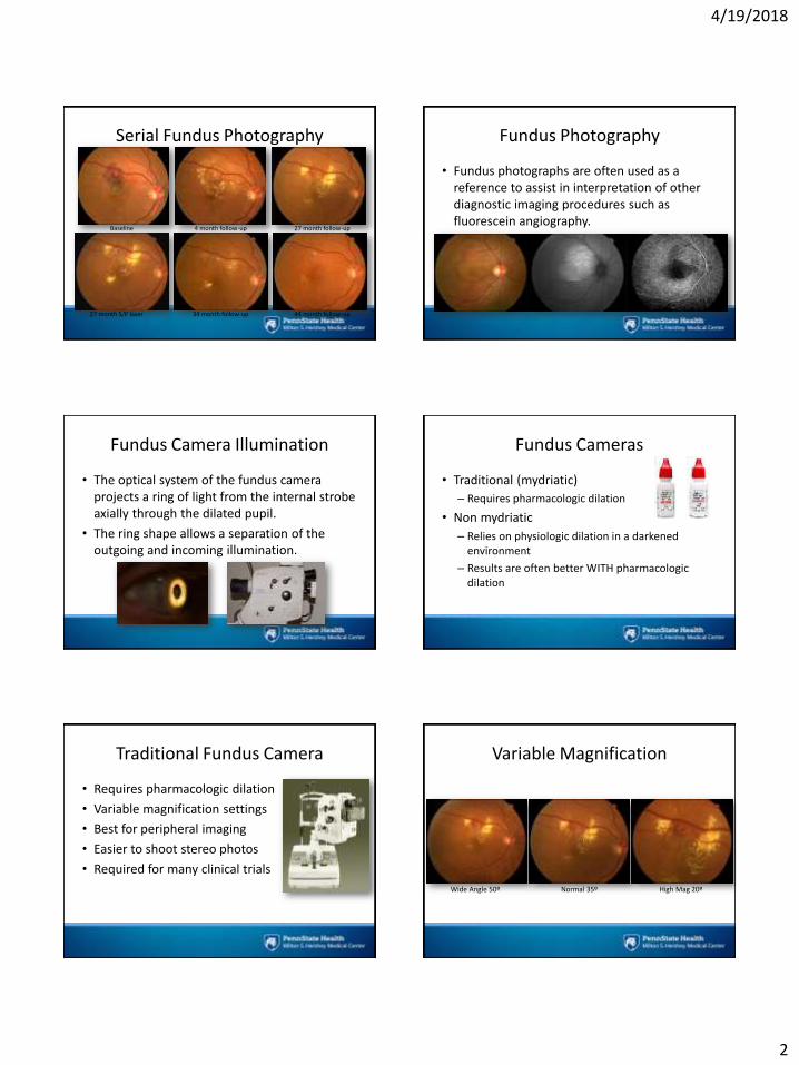
Serial Fundus Photography
Baseline 4 month follow-up 27 month follow-up
44 month follow-up34 month follow-up27 month S/P laser
Fundus Photography
• Fundus photographs are often used as a reference to assist in interpretation of other diagnostic imaging procedures such as fluorescein angiography.
Fundus Camera Illumination
• The optical system of the fundus camera projects a ring of light from the internal strobe axially through the dilated pupil.
• The ring shape allows a separation of the outgoing and incoming illumination.
Fundus Cameras
• Traditional (mydriatic)
– Requires pharmacologic dilation
• Non mydriatic
– Relies on physiologic dilation in a darkened environment
– Results are often better WITH pharmacologic dilation
Traditional Fundus Camera
• Requires pharmacologic dilation
• Variable magnification settings
• Best for peripheral imaging
• Easier to shoot stereo photos
• Required for many clinical trials
Variable Magnification
Wide Angle 50º Normal 35º High Mag 20º

4/19/2018
3
Focus
• Optics of patient’s eye.
• Properly set eyepiece.
• Focus control.
• Auxiliary lens for high-plus or high-minus eyes.
• Both the reticle and the retina need to be sharp at the same time.
Focus: Setting the Eyepiece
• Ignore the eyepiece numbers, but pay attention to the crosshairs and retina.
Focus
• Rock focus knob until image is sharp.
• Use myopic or astigmatic control if needed.
• Use green filter to increase contrast while focusing.
Non-Mydriatic Fundus Camera
• User-friendly system designed with an infrared video focusing system that promotes physiologic dilation in a darkened room.
Dilation Monochromatic Fundus Photography
• The practice of imaging the ocular fundus with monochromatic illumination to enhance visibility of various fundus structures or pathologies.
4/19/2018
4
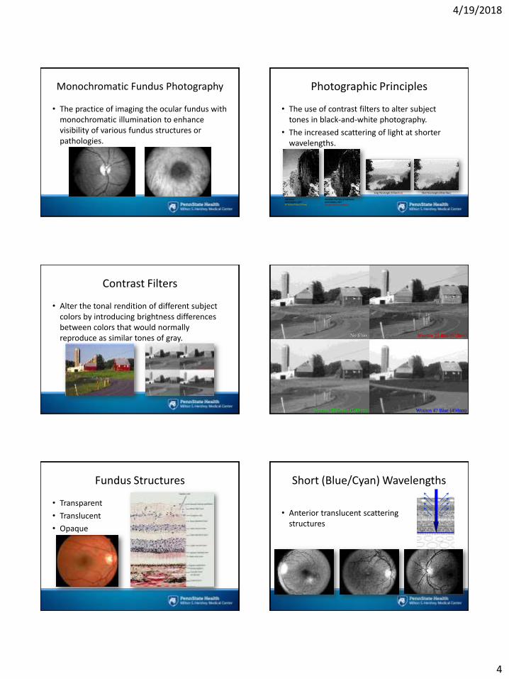
Monochromatic Fundus Photography
• The practice of imaging the ocular fundus with monochromatic illumination to enhance visibility of various fundus structures or pathologies.
Photographic Principles
• The use of contrast filters to alter subject tones in black-and-white photography.
• The increased scattering of light at shorter wavelengths.
Monolith, The Face of Half DomeAnsel Adams, 1927Wratten 29 Filter (630nm)
Half DomeAnsel Adams, 1927K2 Yellow Filter (570nm)
Long Wavelength (615nm Red) Short Wavelength (450nm Blue)
Contrast Filters
• Alter the tonal rendition of different subject colors by introducing brightness differences between colors that would normally reproduce as similar tones of gray.
Contrast Filters
No filter Wratten 25 Red (615nm)
Wratten 47 Blue (450nm)Wratten 58 Green (540nm)
Fundus Structures
• Transparent
• Translucent
• Opaque
Short (Blue/Cyan) Wavelengths
• Anterior translucent scattering structures

4/19/2018
5
Medium (Green) Wavelengths
• Retinal vasculature
• Hemorrhages
• Drusen
• Exudates
Long (Red) Wavelengths
• RPE disturbances
• Choroidal ruptures
• Choroidal nevi
• Melanomas
490nm
540nm 615nm
4/19/2018
6
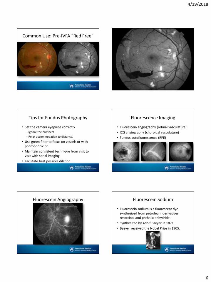
Common Use: Pre-IVFA “Red Free”
Tips for Fundus Photography
• Set the camera eyepiece correctly
– Ignore the numbers
– Relax accommodation to distance.
• Use green filter to focus on vessels or with photophobic pt.
• Maintain consistent technique from visit to visit with serial imaging.
• Facilitate best possible dilation.
Fluorescence Imaging
• Fluorescein angiography (retinal vasculature)
• ICG angiography (choroidal vasculature)
• Fundus autofluorescence (RPE)
Fluorescein Angiography Fluorescein Sodium
• Fluorescein sodium is a fluorescent dye synthesized from petroleum derivatives resorcinol and phthalic anhydride.
• Synthesized by Adolf Baeyer in 1871.
• Baeyer received the Nobel Prize in 1905.

4/19/2018
7
Fluorescein Sodium
• Absorbs blue light, with peak absorption and excitation occurring at wavelengths between 465-490nm.
• Fluorescence occurs at the yellow-green wavelengths of 520 to 530nm.
“More Uses Than Duct Tape”
• Industrial uses:
– Track/measure water flow dynamics
– Track hazardous spill dispersion patterns
– Identify point source of pollutants
– Search and rescue marker
– Detect obstructions or leaks in plumbing/sewage
“More Uses Than Duct Tape”
• Medical uses:
– Intra-operative blood flow in surgical resections
– Monitor chemotherapy in isolated limb perfusion
– Intra-operative predictor of intestinal viability
– Indicator of perfusion in gangrene or severe burns
“More Uses Than Duct Tape”
• Ophthalmic uses:
– Applanation tonometry
– Vital stain for ocular surface disorders
– Nasolacrimal duct obstructions
– Seidel test for corneal wound leaks
Fluorescein Sodium
• In angiography we use the water-soluble sodium salt of fluorescein.
• Maximum fluorescence occurs with a ph of 8 to 9.8.
• 500mg administered as a bolus injection, into the antecubital vein.
Fluorescein Angiography
• First performed by Novotny & Alvis in 1959.
• Can be captured with a fundus camera equipped with exciter/barrier filters or a confocal scanning laser ophthalmoscope.

4/19/2018
8
Exciter and Barrier Filters Color - Grayscale
Phases of an IVFA
• Early: First 45-60 seconds
• Mid: 2-4 minutes
• Late: 7-10 minutes
Sequencing
• The arm-to-retina circulation time varies, but in a normal patient takes 10-12 seconds.
• Rapid sequence photography begins before the dye is visible.
• Images are routinely captured at a rate of 1 fps until maximum fluorescence occurs.
• During this dynamic early phase only one eye can be captured.
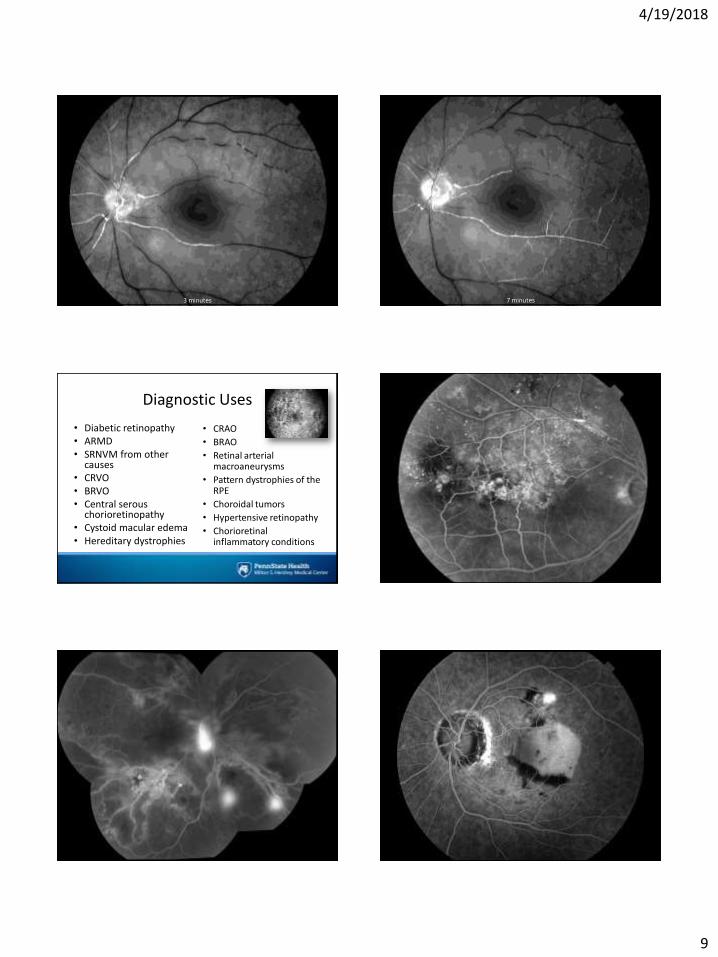
Timed Sequence: Tells a Story
1 minute 3 minutes 7 minutes
1 minute
4/19/2018
9
3 minutes 7 minutes
Diagnostic Uses
• Diabetic retinopathy • ARMD• SRNVM from other
causes • CRVO• BRVO• Central serous
chorioretinopathy• Cystoid macular edema• Hereditary dystrophies
• CRAO
• BRAO
• Retinal arterial macroaneurysms
• Pattern dystrophies of the RPE
• Choroidal tumors
• Hypertensive retinopathy
• Chorioretinal inflammatory conditions
4/19/2018
10
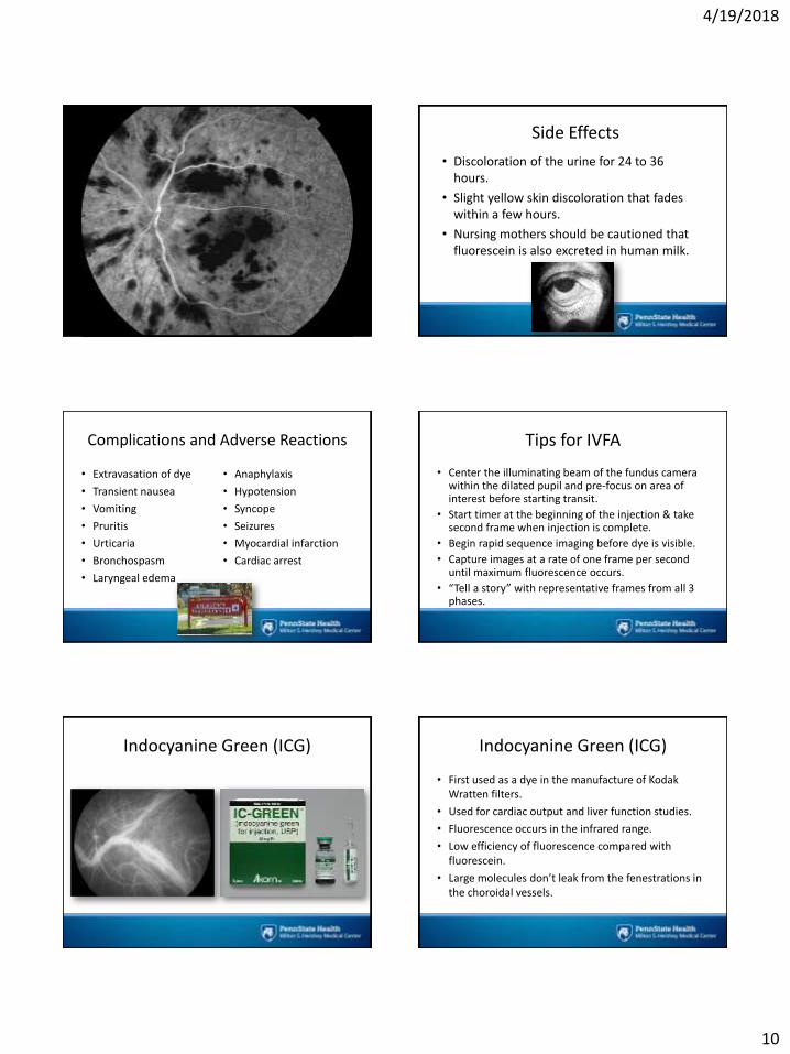
Side Effects
• Discoloration of the urine for 24 to 36 hours.
• Slight yellow skin discoloration that fades within a few hours.
• Nursing mothers should be cautioned that fluorescein is also excreted in human milk.
Complications and Adverse Reactions
• Extravasation of dye
• Transient nausea
• Vomiting
• Pruritis
• Urticaria
• Bronchospasm
• Laryngeal edema
• Anaphylaxis
• Hypotension
• Syncope
• Seizures
• Myocardial infarction
• Cardiac arrest
Tips for IVFA
• Center the illuminating beam of the fundus camera within the dilated pupil and pre-focus on area of interest before starting transit.
• Start timer at the beginning of the injection & take second frame when injection is complete.
• Begin rapid sequence imaging before dye is visible.
• Capture images at a rate of one frame per second until maximum fluorescence occurs.
• “Tell a story” with representative frames from all 3 phases.
Indocyanine Green (ICG) Indocyanine Green (ICG)
• First used as a dye in the manufacture of Kodak Wratten filters.
• Used for cardiac output and liver function studies.
• Fluorescence occurs in the infrared range.
• Low efficiency of fluorescence compared with fluorescein.
• Large molecules don’t leak from the fenestrations in the choroidal vessels.
4/19/2018
11
Indocyanine Green (ICG)
• Peak excitation: 805nm
• Peak emission: 835nm
Ophthalmic Photography. Saine & Tyler, 2002
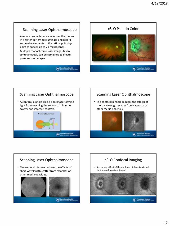
ICG/Near Infrared Wavelengths
• Longer wavelengths allow better penetration through blood and RPE, allowing visualization of the choroidal vasculature.
Image courtesy of Ethan Priel, FOPS
Scanning Laser Ophthalmoscope Scanning Laser Ophthalmoscope
• The confocal scanning laser ophthalmoscope (cSLO) is an instrument that can be used for several imaging modalities including IR, red-free, IVFA, ICG, and fundus autofluorescence.
Clinical Confocal Imaging Devices
• Spectralis HRA
• Optos
• Nidek F-10
• Eidon
cSLO: Spectralis HRA
• 488 nm FA excitation and blue reflectance
• 790 nm ICG excitation
• 820 nm IR reflectance
• 565 nm green reflectance for MultiColor
Red Free 488 nmIR Reflectance 820 nm AF 488 nm
4/19/2018
12
Scanning Laser Ophthalmoscope
• A monochrome laser scans across the fundus in a raster pattern to illuminate and record successive elements of the retina, point-by-point at speeds up to 24 milliseconds.
• Multiple monochrome laser images taken simultaneously can be combined to create pseudo-color images.
cSLO Pseudo Color
Scanning Laser Ophthalmoscope
• A confocal pinhole blocks non image-forming light from reaching the sensor to minimize scatter and improve contrast.
Scanning Laser Ophthalmoscope
• The confocal pinhole reduces the effects of short wavelength scatter from cataracts or other media opacities.
Scanning Laser Ophthalmoscope
• The confocal pinhole reduces the effects of short wavelength scatter from cataracts or other media opacities.
cSLO Confocal Imaging
• Secondary effect of the confocal pinhole is a tonal shift when focus is adjusted.
IR Reflectance 820 nm

4/19/2018
13
Eye Tracking/Sampling
• Smoothes noise and increases exposure
Single frame
Sampled 100x
Fundus Autofluorescence (FAF)
Fundus Autofluorescence (FAF)
• The term “autofluorescence” is used to distinguish fluorescence that can occur naturally from fluorescence that is derived from administration of fluorescent dyes.
• Optic nerve drusen, astrocytic hamartomas, lipofuscin pigments in the retina, and cataracts can exhibit natural fluorescence.
Fundus Autofluorescence (FAF)
• Lipofuscin is a fluorescent pigment that accumulates in the RPE as a metabolic byproduct of cell function.
• Lipofuscin deposition normally increases with age, but may also occur from RPE cell dysfunction or an abnormal metabolic load on the RPE.
4/19/2018
14
Fundus Autofluorescence
• Fundus autofluorescence can be captured with either a modified fundus camera or cSLO.
FAF Findings
• The optic nerve, retinal blood vessels, and the fovea normally appear dark against a variable background of fluorescence from the RPE.
• The absence of the RPE at the optic nerve head causes it to appear dark.
Findings/Interpretation
• Hyperfluorescence is a sign of increased lipofuscin accumulation, which may indicate degenerative changes or oxidative injury.
• Hypofluorescence usually indicates missing or dead RPE cells.
Documentary vs. Diagnosis
• Documentary:
– Geographic atrophy
– Pigmentary changes (RP, ICSC…)
• Diagnostic:
– Early detection of bullseye/retinal toxicity
– Buried disc drusen
– ICSC activity/leakage?
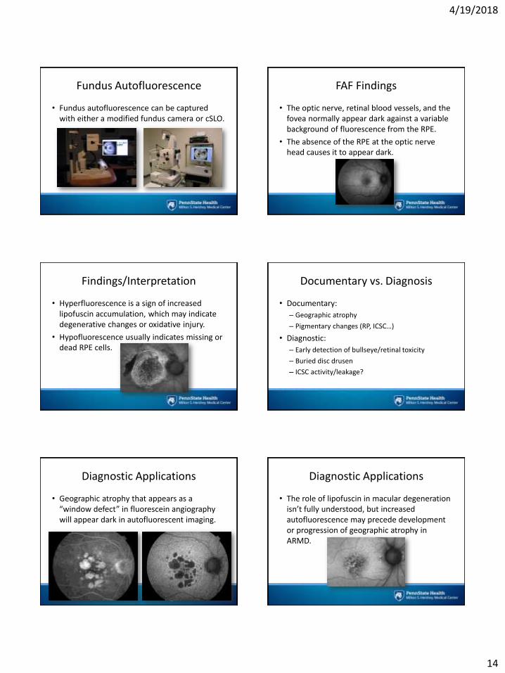
Diagnostic Applications
• Geographic atrophy that appears as a “window defect” in fluorescein angiography will appear dark in autofluorescent imaging.
Diagnostic Applications
• The role of lipofuscin in macular degeneration isn’t fully understood, but increased autofluorescence may precede development or progression of geographic atrophy in ARMD.
4/19/2018
15
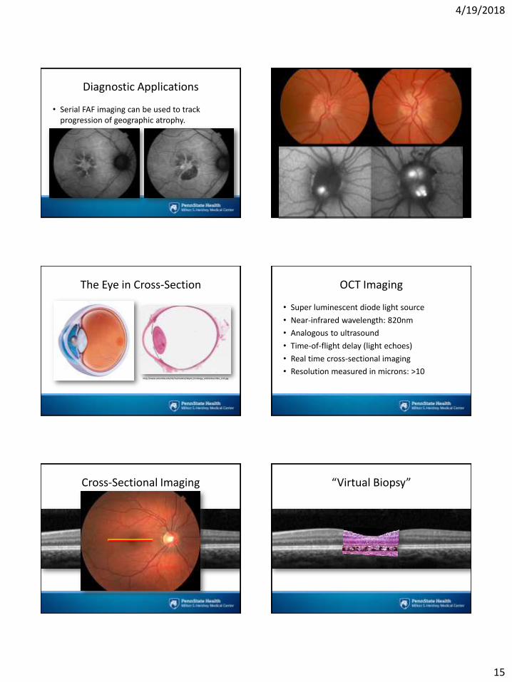
Diagnostic Applications
• Serial FAF imaging can be used to track progression of geographic atrophy.
Disc Drusen
The Eye in Cross-Section
http://www.columbia.edu/itc/hs/medical/sbpm_histology_old/slides/slide_119.jpg
OCT Imaging
• Super luminescent diode light source
• Near-infrared wavelength: 820nm
• Analogous to ultrasound
• Time-of-flight delay (light echoes)
• Real time cross-sectional imaging
• Resolution measured in microns: >10
Cross-Sectional Imaging “Virtual Biopsy”
4/19/2018
16
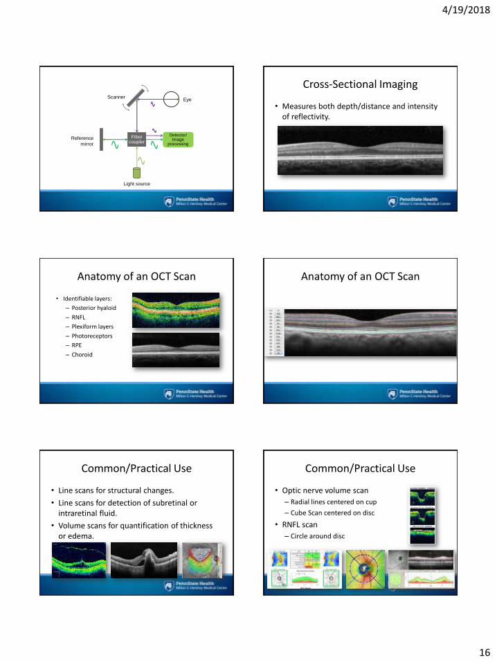
Fiber coupler
Eye
Light source
Scanner
Reference
mirror
Detector/Image
processing
Cross-Sectional Imaging
• Measures both depth/distance and intensity of reflectivity.
Anatomy of an OCT Scan
• Identifiable layers:
– Posterior hyaloid
– RNFL
– Plexiform layers
– Photoreceptors
– RPE
– Choroid
Anatomy of an OCT Scan
Common/Practical Use
• Line scans for structural changes.
• Line scans for detection of subretinal or intraretinal fluid.
• Volume scans for quantification of thickness or edema.
Common/Practical Use
• Optic nerve volume scan
– Radial lines centered on cup
– Cube Scan centered on disc
• RNFL scan
– Circle around disc

4/19/2018
17
Anatomical Landmarks Anatomical Landmarks
Anatomical Landmarks
• Anatomically, the fovea sits 5-7 degrees below the midpoint of the disc.
Anatomical Landmarks
Scanning Technique
• Pupils dilated?
• Head/chin straight and square.
• Encourage normal blinking pattern.
• Start with fast scan protocol.
• Optimize polarization (“Enhance”).
• Don’t forget focus.
• Move joystick (or mouse controls) to maximize signal “sweetspot”.
Scanning Strategies
• Start with “Fast” or “HS” volume scans as a quick overview and watch for pathology during acquisition
– Fast Macular Thickness or Macular Cube Scan

4/19/2018
18
Scanning Strategies
• High-resolution horizontal & vertical single line scans centered on fovea.
Scanning Strategies
• Free-scan or pan to detect subtle pathology.
• “Anchor” scan on known landmark.
• “Repeat” function restores settings from previous scans for consistency when doing custom scans.
Fixation Issues
• Macular pathology often makes it difficult for patients to establish or maintain central fixation.
Eccentric Fixation
• Let patient establish fixation.
• Capture scans on fixation first.
• Then try to center scan pattern over fovea or area of pathology & repeat:
– click and drag the scan pattern over foveal depression (if visible).
– “Anchor” scan on disc margin if depression isn’t identifiable.
“Anchor” Scan “Anchor” Scan
4/19/2018
19
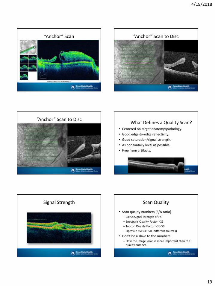
“Anchor” Scan
Image courtesy of Gary Miller, CRA, OCT-C
“Anchor” Scan to Disc
“Anchor” Scan to DiscWhat Defines a Quality Scan?
• Centered on target anatomy/pathology.
• Good edge-to-edge reflectivity.
• Good saturation/signal strength.
• As horizontally level as possible.
• Free from artifacts.
Signal Strength Scan Quality
• Scan quality numbers (S/N ratio)
– Cirrus Signal Strength of >5
– Spectralis Quality Factor >25
– Topcon Quality Factor >30-50
– Optovue SSI >35-50 (different sources)
• Don’t be a slave to the numbers!
– How the image looks is more important than the quality number.

4/19/2018
20
Signal Strength
• Focus
• Polarization
• Z-offset
• Alignment within pupil
• Media opacities
• Tear film disruption
• Dirt/debris on objective
Signal Strength/Focus
Images courtesy of Gary Miller, CRA, OCT-C
Signal Strength/Focus
Images courtesy of Gary Miller, CRA, OCT-C
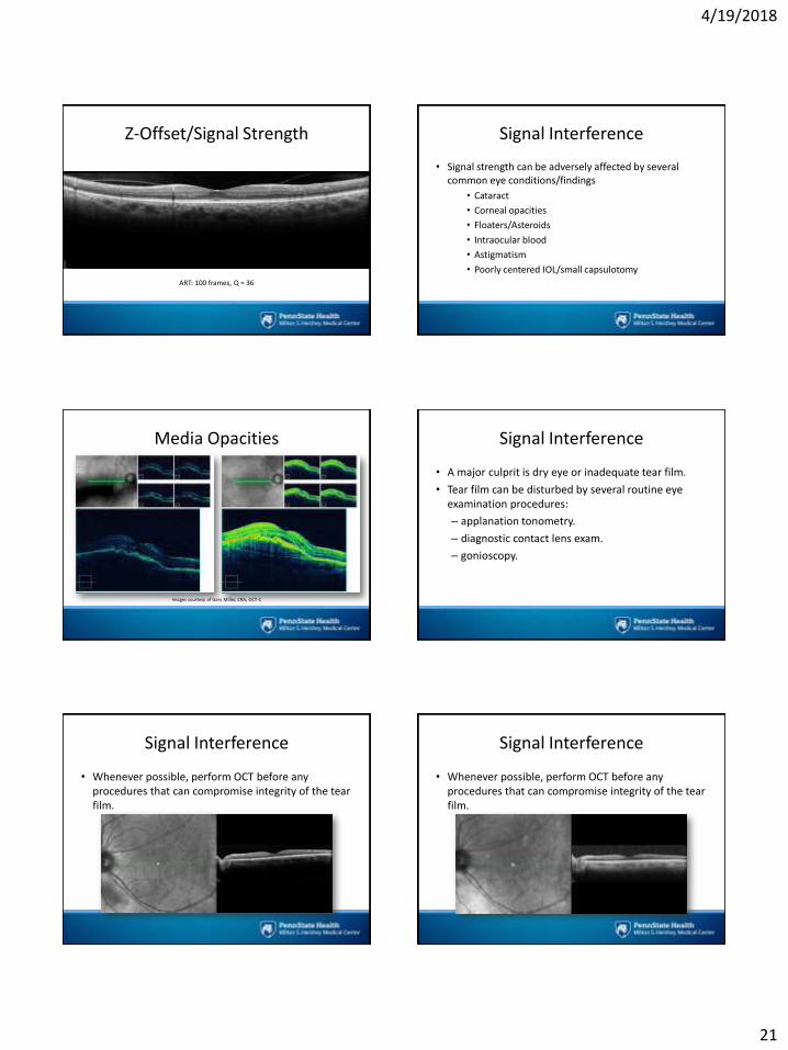
Z-Offset/Signal Strength
Z-Offset/Signal Strength
ART: 100 frames, Q = 20
Z-Offset/Signal Strength
ART: 100 frames, Q = 28
4/19/2018
21
Z-Offset/Signal Strength
ART: 100 frames, Q = 36
Signal Interference
• Signal strength can be adversely affected by several common eye conditions/findings
• Cataract
• Corneal opacities
• Floaters/Asteroids
• Intraocular blood
• Astigmatism
• Poorly centered IOL/small capsulotomy
Media Opacities
Images courtesy of Gary Miller, CRA, OCT-C
Signal Interference
• A major culprit is dry eye or inadequate tear film.
• Tear film can be disturbed by several routine eye examination procedures:
– applanation tonometry.
– diagnostic contact lens exam.
– gonioscopy.
Signal Interference
• Whenever possible, perform OCT before any procedures that can compromise integrity of the tear film.
Signal Interference
• Whenever possible, perform OCT before any procedures that can compromise integrity of the tear film.
4/19/2018
22
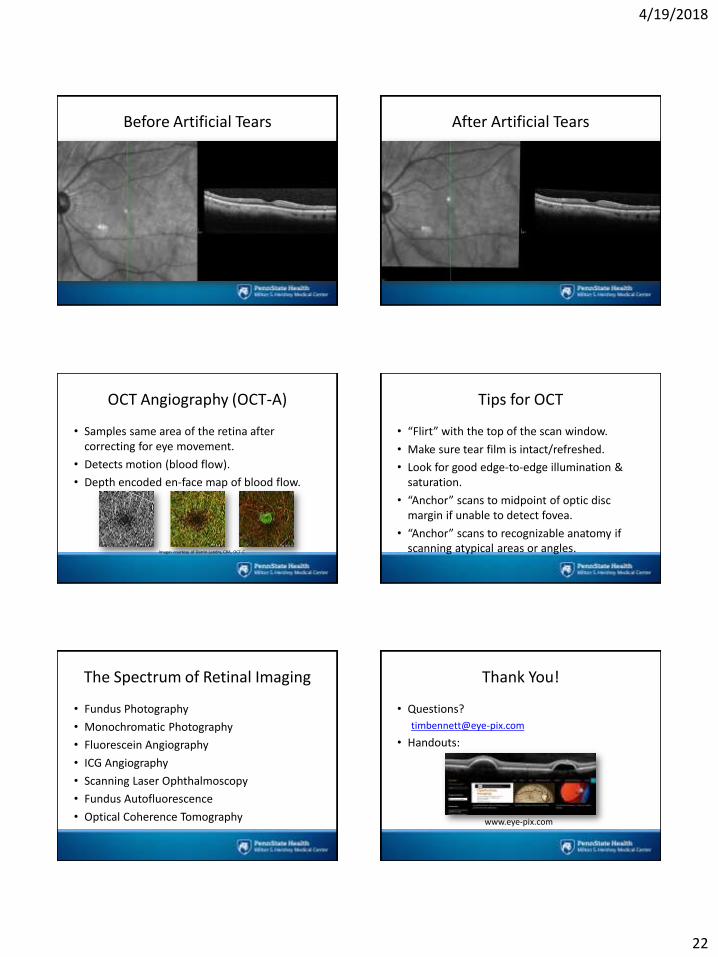
Before Artificial Tears After Artificial Tears
OCT Angiography (OCT-A)
• Samples same area of the retina after correcting for eye movement.
• Detects motion (blood flow).
• Depth encoded en-face map of blood flow.
Images courtesy of Darrin Landry, CRA, OCT-C
Tips for OCT
• “Flirt” with the top of the scan window.
• Make sure tear film is intact/refreshed.
• Look for good edge-to-edge illumination & saturation.
• “Anchor” scans to midpoint of optic disc margin if unable to detect fovea.
• “Anchor” scans to recognizable anatomy if scanning atypical areas or angles.
The Spectrum of Retinal Imaging
• Fundus Photography
• Monochromatic Photography
• Fluorescein Angiography
• ICG Angiography
• Scanning Laser Ophthalmoscopy
• Fundus Autofluorescence
• Optical Coherence Tomography
Thank You!
• Questions?
• Handouts:
www.eye-pix.com
4/19/2018
23
The Spectrum of Retinal Imaging
Timothy J. Bennett, CRA, FOPS, OCT-C
Penn State Eye Center
Hershey, PA
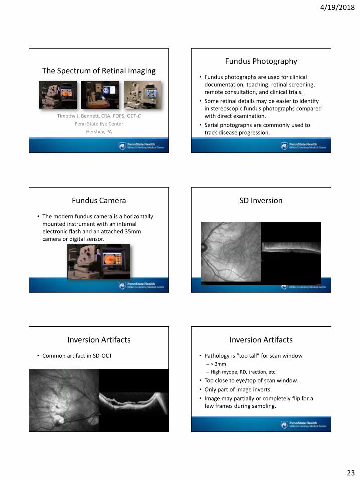
Fundus Photography
• Fundus photographs are used for clinical documentation, teaching, retinal screening, remote consultation, and clinical trials.
• Some retinal details may be easier to identify in stereoscopic fundus photographs compared with direct examination.
• Serial photographs are commonly used to track disease progression.
Fundus Camera
• The modern fundus camera is a horizontally mounted instrument with an internal electronic flash and an attached 35mm camera or digital sensor.
SD Inversion
Inversion Artifacts
• Common artifact in SD-OCT
Inversion Artifacts
• Pathology is “too tall” for scan window
– > 2mm
– High myope, RD, traction, etc.
• Too close to eye/top of scan window.
• Only part of image inverts.
• Image may partially or completely flip for a few frames during sampling.
4/19/2018
24
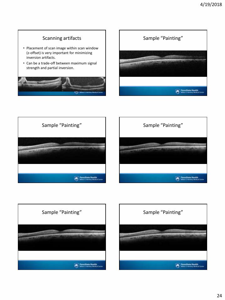
Scanning artifacts
• Placement of scan image within scan window (z-offset) is very important for minimizing inversion artifacts.
• Can be a trade-off between maximum signal strength and partial inversion.
Sample “Painting”
Sample “Painting” Sample “Painting”
Sample “Painting” Sample “Painting”
4/19/2018
25
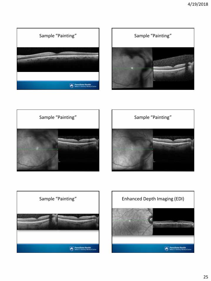
Sample “Painting” Sample “Painting”
Sample “Painting” Sample “Painting”
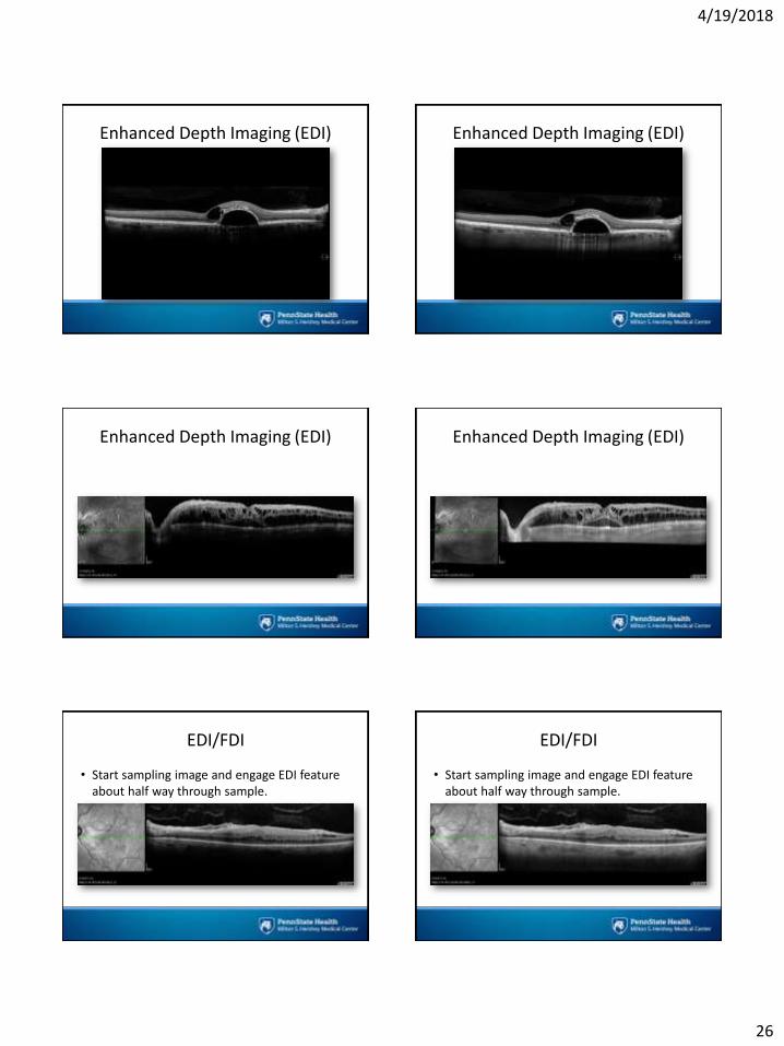
Sample “Painting” Enhanced Depth Imaging (EDI)
4/19/2018
26
Enhanced Depth Imaging (EDI) Enhanced Depth Imaging (EDI)
Enhanced Depth Imaging (EDI) Enhanced Depth Imaging (EDI)
EDI/FDI
• Start sampling image and engage EDI feature about half way through sample.
EDI/FDI
• Start sampling image and engage EDI feature about half way through sample.

4/19/2018
27
Inversion Artifacts
• Pathology is “too tall” for scan window
– > 2mm
– High myope, RD, traction, etc.
• Too close to eye/top of scan window.
• Only part of image inverts.
• Image may partially or completely flip for a few frames during sampling.
Inversion Artifacts
Inversion Artifacts Inversion Artifacts
Images courtesy of Bridgette Staffaroni, COT
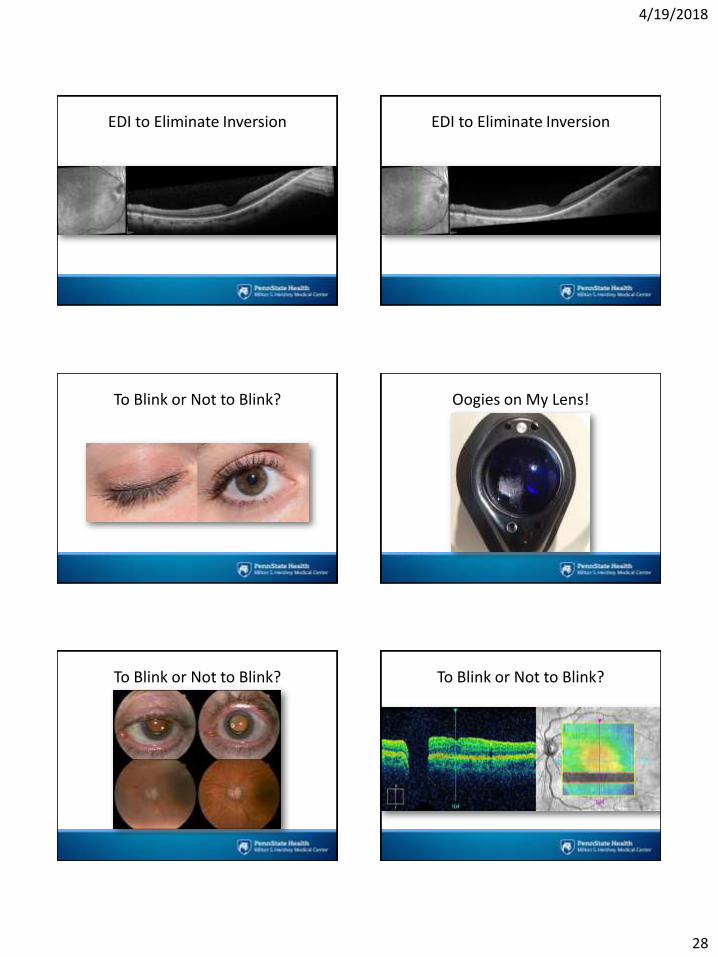
EDI to Eliminate Inversion EDI to Eliminate Inversion
4/19/2018
28
EDI to Eliminate Inversion EDI to Eliminate Inversion
To Blink or Not to Blink? Oogies on My Lens!
To Blink or Not to Blink? To Blink or Not to Blink?
4/19/2018
29
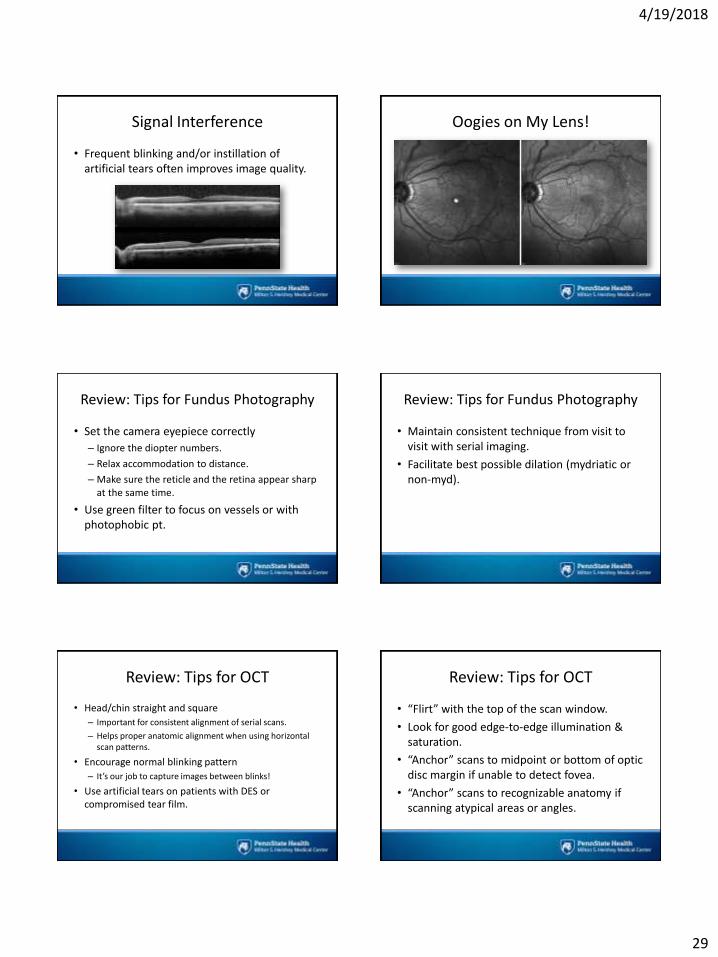
Signal Interference
• Frequent blinking and/or instillation of artificial tears often improves image quality.
Oogies on My Lens!
Review: Tips for Fundus Photography
• Set the camera eyepiece correctly
– Ignore the diopter numbers.
– Relax accommodation to distance.
– Make sure the reticle and the retina appear sharp at the same time.
• Use green filter to focus on vessels or with photophobic pt.
Review: Tips for Fundus Photography
• Maintain consistent technique from visit to visit with serial imaging.
• Facilitate best possible dilation (mydriatic or non-myd).
Review: Tips for OCT
• Head/chin straight and square
– Important for consistent alignment of serial scans.
– Helps proper anatomic alignment when using horizontal scan patterns.
• Encourage normal blinking pattern
– It’s our job to capture images between blinks!
• Use artificial tears on patients with DES or compromised tear film.
Review: Tips for OCT
• “Flirt” with the top of the scan window.
• Look for good edge-to-edge illumination & saturation.
• “Anchor” scans to midpoint or bottom of optic disc margin if unable to detect fovea.
• “Anchor” scans to recognizable anatomy if scanning atypical areas or angles.

4/19/2018
30
Thank You!
• Questions?
• Handouts:
http://eye-pix.com/event/lecture-tips-and-tactics-for-retinal-imaging/
Common Uses of OCT
• Line scans for structural changes
• Line scans for detection of subretinal or intraretinal fluid
• Volume scans/maps for measurement of thickness or swelling
Fundus Camera Fundus Photography