powerstock—calorifier range - hevac · 6.4 contactor current rating for immersion heaters on...
TRANSCRIPT

Powerstock—Calorifier Range
Equipment For Commercial Potable Hot Water Installations.
INSTALLATION, COMMISSIONING AND SERVICING INSTRUCTIONS
IMPORTANT NOTE
THESE INSTRUCTIONS MUST BE READ
AND UNDERSTOOD BEFORE INSTALLING,
COMMISSIONING, OPERATING OR
SERVICING EQUIPMENT


HAMWORTHY HEATING LTD
POWERSTOCK
500001084/R
Powerstock Calorifier
Models PS160, PS200, PS300 PS400, PS500, PS750 & PS1000
INSTALLATION, COMMISSIONING AND SERVICING INSTRUCTIONS
THE POWERSTOCK CALORIFIER IS INTENDED FOR USE AS A COMMERCIAL APPLIANCE.
PUBLICATION NO. 500001084 ISSUE 'R‘ OCTOBER 2013
i

HAMWORTHY HEATING LTD
POWERSTOCK
500001084/R
ii
CONTENTS
PAGE 1.0 INTRODUCTION ................................................................................................................................ 1 2.0 TECHNICAL DATA ............................................................................................................................ 1 3.0 GENERAL REQUIREMENTS ............................................................................................................ 1 3.1 Related Documents 4.0 LOCATION ........................................................................................................................................ 2 5.0 WATER CIRCULATION GENERAL ................................................................................................. 2 6.0 ELECTRICAL SUPPLY ..................................................................................................................... 2 7.0 INSTALLATION ................................................................................................................................. 2 7.1 General 7.2 Water Connections 7.2.1 Coil Connection (series flow) kit 7.2.2 Vented applications 7.2.3 Unvented applications 7.2.3.1 Unvented controls 7.3 Control box installation 7.4 Installation of optional kits 8.0 COMMISSIONING AND TESTING .................................................................................................... 5 9.0 SERVICING AND SPARES ............................................................................................................... 6 FIGURES 1.2 Technical Data .................................................................................................................................. 7 1.3 Single Coil Input Graphs.................................................................................................................. 8 1.4 Single Coil Input Graphs - Cont’d ................................................................................................... 9 1.5 Dual Coil Input Graphs ................................................................................................................... 10 2.1 General Layout and Dimensional Data ......................................................................................... 11 5.1 Hot Water Applications: Vented Systems .................................................................................... 19 5.2 Hot Water Applications: Unvented Systems ............................................................................... 20 5.3 Hot Water Applications: Boosted System ................................................................................... 21 6.1 Schematic Wiring Diagram of the Control Box ........................................................................... 26 6.2 Typical Wiring of a Powerstock Calorifier to a Boiler................................................................. 26 6.3 Typical Immersion Heater Control System For A Powerstock Calorifier ................................. 28 6.4 Contactor Current Rating For Immersion Heaters On Single Phase & 3 Phase Supplies ...... 29 6.5 Wiring Schematic for Switching A Primary Heating Coil Pump ............................................... 29 7.1 Levelling Feet Assembly ............................................................................................................... 30 7.2.1 Coil Connection (series flow) Kit .................................................................................................. 30 7.2.3 Unvented Applications .................................................................................................................. 31 7.3 Control Box Layout ........................................................................................................................ 25 7.4 Earth Tag Assembly ...................................................................................................................... 25 9.2 Clean Out Door Flange Type ......................................................................................................... 32 10.1 Top to Bottom Circulation ............................................................................................................. 33 11.0 PS160 assembly ............................................................................................................................. 12 12.0 PS200 assembly ............................................................................................................................. 13 13.0 PS300 assembly ............................................................................................................................. 14 14.0 PS400 assembly ............................................................................................................................. 15 15.0 PS500 assembly ............................................................................................................................. 16 16.0 PS750 assembly ............................................................................................................................. 17 17.0 PS1000 assembly .......................................................................................................................... 18
HAMWORTHY HEATING LTD
POWERSTOCK
500001084/R
1
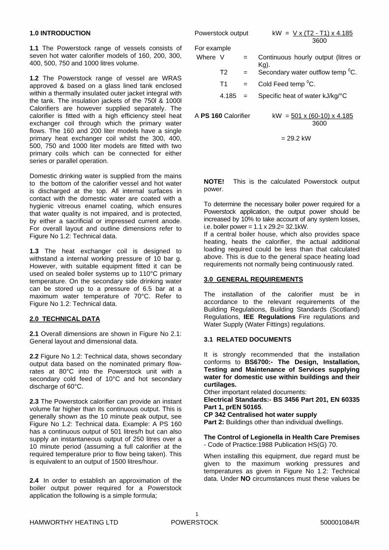
1.0 INTRODUCTION 1.1 The Powerstock range of vessels consists of seven hot water calorifier models of 160, 200, 300, 400, 500, 750 and 1000 litres volume. 1.2 The Powerstock range of vessel are WRAS approved & based on a glass lined tank enclosed within a thermally insulated outer jacket integral with the tank. The insulation jackets of the 750l & 1000l Calorifiers are however supplied separately. The calorifier is fitted with a high efficiency steel heat exchanger coil through which the primary water flows. The 160 and 200 liter models have a single primary heat exchanger coil whilst the 300, 400, 500, 750 and 1000 liter models are fitted with two primary coils which can be connected for either series or parallel operation.
Domestic drinking water is supplied from the mains to the bottom of the calorifier vessel and hot water is discharged at the top. All internal surfaces in contact with the domestic water are coated with a hygienic vitreous enamel coating, which ensures that water quality is not impaired, and is protected, by either a sacrificial or impressed current anode. For overall layout and outline dimensions refer to Figure No 1.2: Technical data. 1.3 The heat exchanger coil is designed to withstand a internal working pressure of 10 bar g. However, with suitable equipment fitted it can be used on sealed boiler systems up to 110°C primary temperature. On the secondary side drinking water can be stored up to a pressure of 6.5 bar at a maximum water temperature of 70°C. Refer to Figure No 1.2: Technical data. 2.0 TECHNICAL DATA 2.1 Overall dimensions are shown in Figure No 2.1: General layout and dimensional data.
2.2 Figure No 1.2: Technical data, shows secondary output data based on the nominated primary flow-rates at 80°C into the Powerstock unit with a secondary cold feed of 10°C and hot secondary discharge of 60°C.
2.3 The Powerstock calorifier can provide an instant volume far higher than its continuous output. This is generally shown as the 10 minute peak output, see Figure No 1.2: Technical data. Example: A PS 160 has a continuous output of 501 litres/h but can also supply an instantaneous output of 250 litres over a 10 minute period (assuming a full calorifier at the required temperature prior to flow being taken). This is equivalent to an output of 1500 litres/hour.
2.4 In order to establish an approximation of the boiler output power required for a Powerstock application the following is a simple formula;
NOTE! This is the calculated Powerstock output power. To determine the necessary boiler power required for a Powerstock application, the output power should be increased by 10% to take account of any system losses, i.e. boiler power = 1.1 x 29.2= 32.1kW. If a central boiler house, which also provides space heating, heats the calorifier, the actual additional loading required could be less than that calculated above. This is due to the general space heating load requirements not normally being continuously rated. 3.0 GENERAL REQUIREMENTS
The installation of the calorifier must be in accordance to the relevant requirements of the Building Regulations, Building Standards (Scotland) Regulations, IEE Regulations Fire regulations and Water Supply (Water Fittings) regulations. 3.1 RELATED DOCUMENTS It is strongly recommended that the installation conforms to BS6700:- The Design, Installation, Testing and Maintenance of Services supplying water for domestic use within buildings and their curtilages. Other important related documents: Electrical Standards:- BS 3456 Part 201, EN 60335 Part 1, prEN 50165. CP 342 Centralised hot water supply Part 2: Buildings other than individual dwellings. The Control of Legionella in Health Care Premises - Code of Practice:1988 Publication HS(G) 70.
When installing this equipment, due regard must be given to the maximum working pressures and temperatures as given in Figure No 1.2: Technical data. Under NO circumstances must these values be
Powerstock output kW = V x (T2 - T1) x 4.185 3600 For example
A PS 160 Calorifier kW = 501 x (60-10) x 4.185 3600 = 29.2 kW
Where V = Continuous hourly output (litres or Kg).
T2 = Secondary water outflow temp 0C.
T1 = Cold Feed temp 0C.
4.185 = Specific heat of water kJ/kg/°C
HAMWORTHY HEATING LTD
POWERSTOCK
500001084/R
2
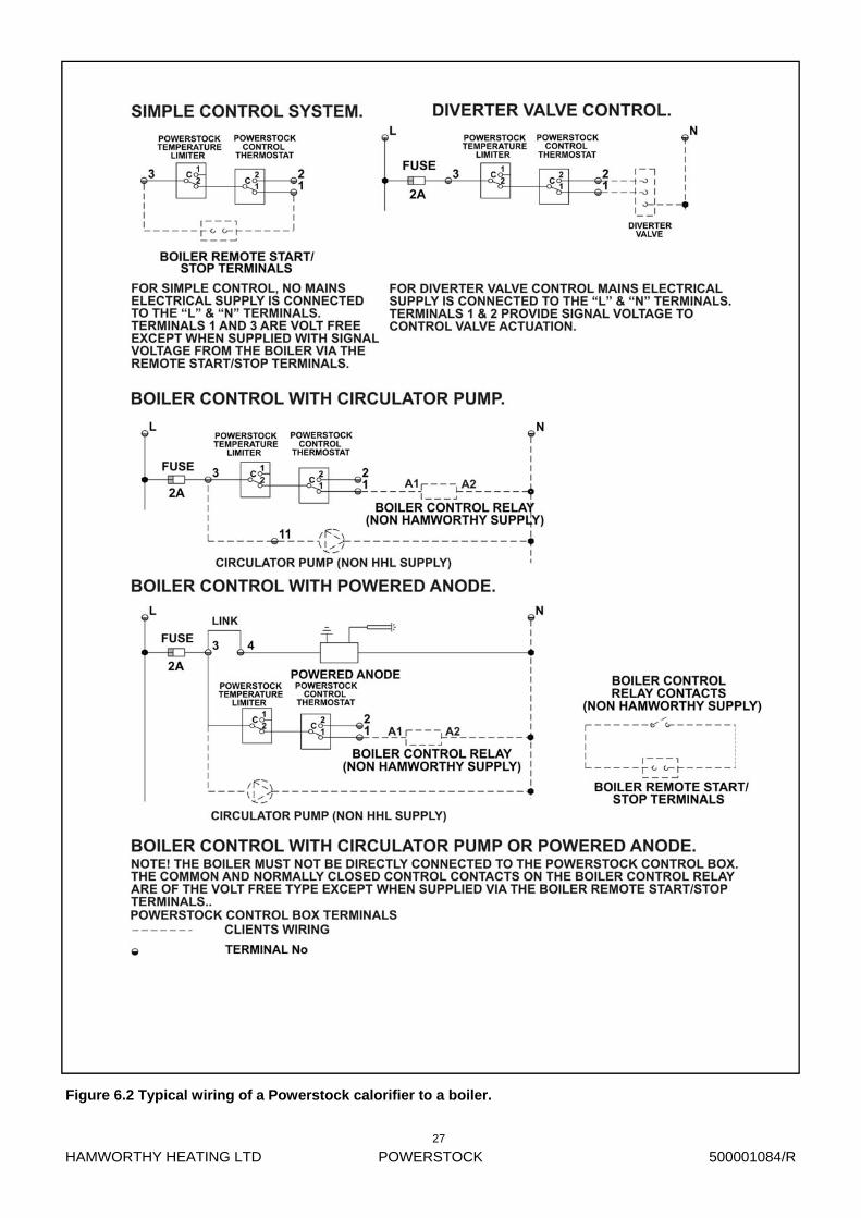
wiring of a Powerstock calorifier to a boiler. The sacrificial/powered anode must be connected
to a suitable earthing point via a suitable earthing strap. It should not be assumed that a reliable earth path is available through the water connections. The Hamworthy powered anode kit is provided with an earth crimp, refer to Figure No 7.4: Earth tag assembly.
All wiring to the calorifier should be completed in heat resistant 1 mm2. 3 core cable. For powered anode applications it is necessary to provide a permanent power supply that is uninterrupted by time clocks etc in order to provide continuous protection. 7.0 INSTALLATION 7.1 GENERAL. For typical Domestic hot water installation schematic diagrams see Figure No’s. 5.1, 5.2, and 5.3.
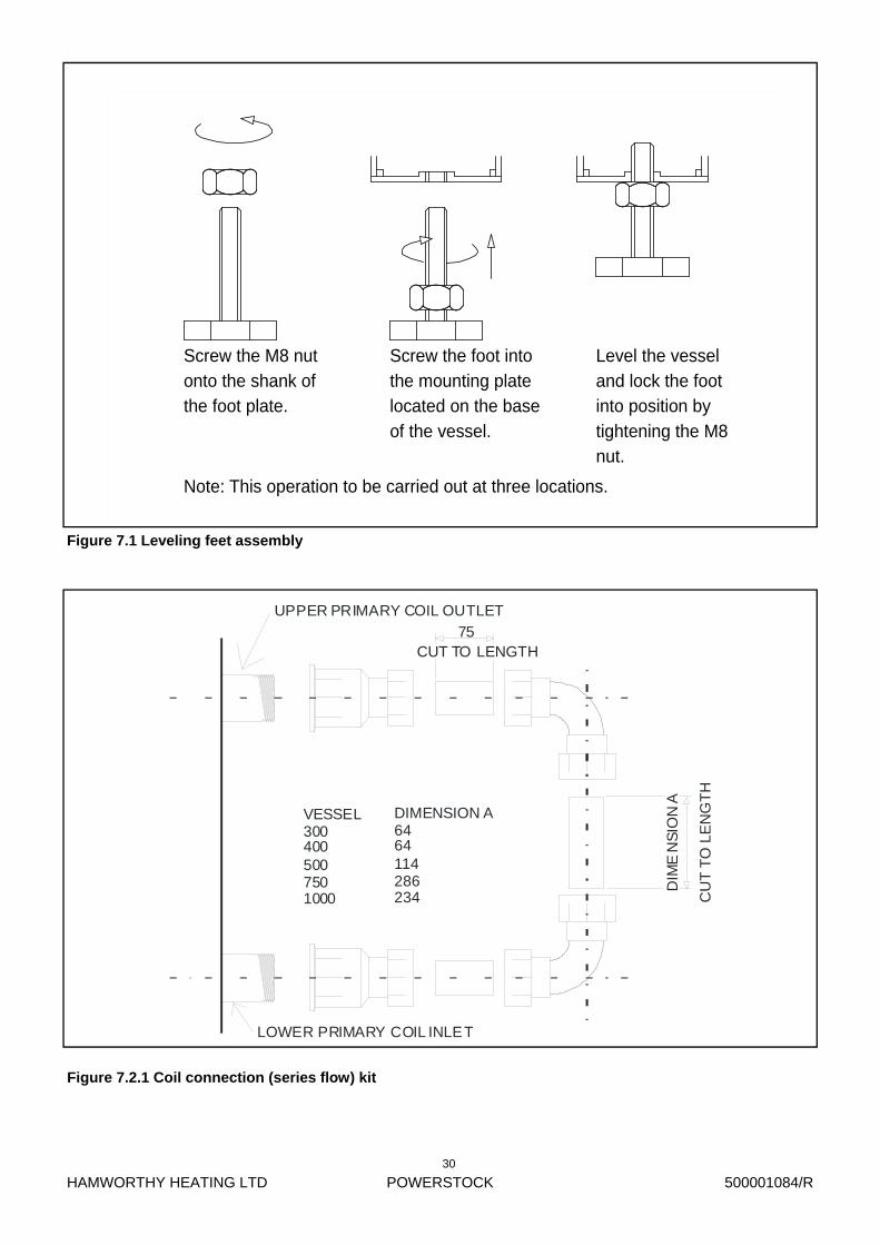
Overall dimension and connection details are shown in Figure No 2.1: General layout and dimensional data. The installation should conform to the recommendations given in BS6700 and any other relevant codes of practice. The calorifier must be installed on a level concrete floor or plinth which is sufficient to support its weight when filled with water. See Figure No 1.2: Technical data. For minor floor irregularities three leveling feet are supplied (contained in a bag attached to the cold feed inlet) which can be screwed directly into the support plates at the base of the vessel. See Figure No 7.1: Leveling feet assembly. Note the vessel should be mounted on the adjustable feet or a suitable plinth to ensure that there will be sufficient elevation of the cold water feed pipe to allow for wrench clearance when connecting fittings. 7.2 WATER CONNECTIONS Refer to Figure No 2.1: General layout and dimensional data. 7.2.1 COIL CONNECTION (SERIES FLOW) KIT The 300, 400, 500, 750 & 1000 litre vessels are fitted with two independent coils that can be connected either in series or parallel to increase output performance of the vessel over that of the single coil. A series flow kit is provided with each vessel to enable the connection of the two coils, refer to Figure No 7.2.1:Coil connection (series flow) kit.
7.2.2 VENTED APPLICATIONS Refer to Figure No 5.1: Hot water applications. The tank and water supply from it must be sized to ensure that the make-up water flow is equivalent to, or exceeds, the maximum draw off rate of the calorifier and any
4.0 LOCATION 4.1 Refer to Figure No 2.1: General layout and dimensional data, for overall dimensions, weights and clearances required. The location chosen must provide adequate space for servicing and inspection as required. The calorifier must be installed on a level surface capable of adequately supporting its weight (when filled with water) and any ancillary equipment fitted. The insulation jacket’s surface must not be subjected to direct heat or radiation and must be protected from contact with boiler flues, etc. 5.0 WATER CIRCULATION GENERAL 5.1 Refer to Section 3.1 RELATED DOCUMENTS for detailed advice on water circuit installation. Points of use mixing valves are recommended at each outlet to ensure high water temperatures are not discharged. All circulation pipework must be lagged to prevent heat loss and possible freezing, especially where pipes run through roof spaces and ventilated cavities. Tanks situated in areas that may be exposed to freezing conditions should also be insulated. Drain valves must be located in accessible positions to permit the draining of the complete secondary water storage system and pipework. Directly after installation, the complete system must be flushed through with a suitable disinfectant to thoroughly clean all materials in contact with the water. The calorifier should be flushed through several times to ensure removal of the disinfectant. For schematic details of typical Domestic hot water systems see Figure No’s 5.1, 5.2 and 5.3. 6.0 ELECTRICAL SUPPLY 6.1 WARNING: THIS APPLIANCE MUST BE EARTHED. All wiring must be installed to comply with the relevant IEE Regulations. It must also be installed and checked by a suitably competent person.
Normal supply required is 230 volts 50Hz single phase - fused at 2 amps. A temperature limiter and thermostat are fitted inside the control box for temperature control purposes. Any voltage up to 230 volts AC can be used with external control systems. See Figure No’s 6.1 and 6.2. NOTE! If the unit is controlled from a Purewell or other boiler with remote start/stop control, it is imperative that the wiring of the Powerstock control box is of the volt free configuration. It is advisable to utilize an external relay to control this type of boiler. See Figure No 6.2: Typical wiring of a Powerstock calorifier to a boiler. If a top to bottom circulator or powered anode is specified, these can be wired back to the Powerstock control box. See Figure No 6.2: Typical
HAMWORTHY HEATING LTD
POWERSTOCK
500001084/R
3
other system requirements. The hot water flow pipe from the calorifier must
be fitted with an open vent connection. The vent should be sized as follows and rise to discharge over the feed tank. PS160 & 200 > 19mm clear bore. PS 300 to 500 > 26mm clear bore. PS 750 to 1000 > 32mm clear bore. The vent pipe shall be protected against freezing where this might occur. No isolating valves should be fitted between the calorifier hot water outlet and the connection point of the vent. The maximum hot working head of the Powerstock calorifier is 10 bar g. (102 metres). Dead legs to water draw off points should be as short as possible and in no case should they exceed the lengths laid down in the water regulations guide. For example:
7.2.3.1. UNVENTED CONTROLS. 7.2.3.1.1 SECONDARY HOT WATER SIDE. The pressure temperature relief valve must be fitted directly into the vessel at the location indicated in Figure No 2.1. Remove the ABS top cover from the vessel exposing the top connection point. Remove the 1” BSP brass plug and screw the P & T, relief valve into this position using a suitable WRAS approved jointing compound. Cut a 130mm-diameter hole in the centre of the ABS top cover to clear the P & T, relief valve then refit the cover to the vessel. The installation of pipework from the P & T, relief valve outlet should conform to the recommendations given in BS6700 and any other relevant codes of practice. 7.2.3.1.2 COLD WATER FEED SIDE. For typical installation applications refer to Figures No’s 5.2 and 5.3. The Hamworthy Heating valve train is sized to provide flow rates of approximately 4800 l/h under the assumed conditions of 2 bar incoming mains water pressure and 1 bar static back pressure resulting from the highest distribution lines above the vessel and flow resistances of the system. Potential flows will increase with higher mains pressures up to the 3.5 bar preset regulator pressure. However due to the many variables involved it is recommended that the flow rate of 4800 l/h is considered the maximum. An expansion vessel that is pre-charged at 3.5 bar and sized to accept the water expansion volume from a Powerstock and its local associated pipework is supplied with each un-vented Powerstock. If the water train is serving a large distribution system additional expansion vessels maybe required and the acceptance volume V2 can be calculated as follows:
7.2.3 UN-VENTED APPLICATIONS Refer to Figure No 5.2. & 5.3. Any un-vented installation must follow the essential safety requirements of the Buildings Regulations part G3 Section 2. This document further states that the system should be designed by appropriately qualified engineers and fitted by approved installers.
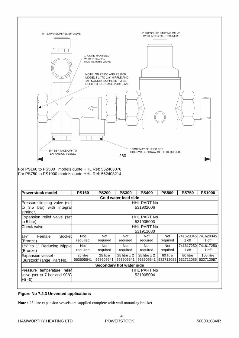
The cold feed un-vented kit(s) offered by Hamworthy Heating comprise a valve train assembly incorporating expansion relief valve, non-return valve, strainer and pressure reducing valve plus a suitably sized expansion vessel compatible with potable water and sized for the unit and local pipework. A temperature/pressure relief valve is also supplied which follows the sizing recommendations from the valve supplier. This ensures adequate protection even with low incoming water mains pressures.
Refer to Figure No 7.2.3: Unvented applications for details and descriptions of kit contents. For comprehensive recommendations on the design, installation and testing of water supply services, attention is drawn to the appropriate sections of BS 6700. The maximum hot working head of the Powerstock calorifier is 10 bar g. (102 metres). Dead legs to water draw off points should be as short as possible and in no case should they exceed the lengths laid down in the water regulations guide.
(i) Pipes < 19mm I/D Maximum dead leg = 12m
(ii) Pipes 19-24mm I/D Maximum dead leg = 7.6m
(iii) Pipes > 25mm I/D Maximum dead leg = 3m
(i) Pipes < 19mm I/D Maximum dead leg = 12m
(ii) Pipes 19-24mm I/D Maximum dead leg = 7.6m
(iii) Pipes > 25mm I/D Maximum dead leg = 3m
V2 =
et x V1
1 –( Pc
Pw )
Where et is the expansion factor which for a 65°C rise = 0.02. V1 is the volume of the entire system including the heater. Pc is the absolute expansion vessel cushion pressure normally preset to 4.5 bar. Absolute = (3.5 bar gauge + 1 bar.) Pw is the absolute working pressure and is the same value as that of the expansion relief valve setting 6 bar. Absolute = (5 bar gauge + 1 bar.) V2 is the volume of the required expansion vessel.
HAMWORTHY HEATING LTD
POWERSTOCK
500001084/R
4
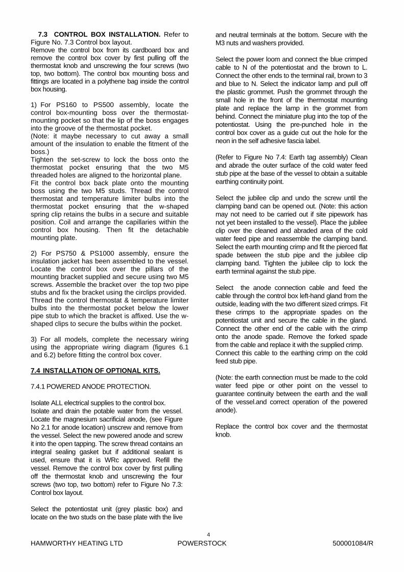
7.3 CONTROL BOX INSTALLATION. Refer to Figure No. 7.3 Control box layout. Remove the control box from its cardboard box and remove the control box cover by first pulling off the thermostat knob and unscrewing the four screws (two top, two bottom). The control box mounting boss and fittings are located in a polythene bag inside the control box housing. 1) For PS160 to PS500 assembly, locate the control box-mounting boss over the thermostat-mounting pocket so that the lip of the boss engages into the groove of the thermostat pocket. (Note: it maybe necessary to cut away a small amount of the insulation to enable the fitment of the boss.) Tighten the set-screw to lock the boss onto the thermostat pocket ensuring that the two M5 threaded holes are aligned to the horizontal plane. Fit the control box back plate onto the mounting boss using the two M5 studs. Thread the control thermostat and temperature limiter bulbs into the thermostat pocket ensuring that the w-shaped spring clip retains the bulbs in a secure and suitable position. Coil and arrange the capillaries within the control box housing. Then fit the detachable mounting plate. 2) For PS750 & PS1000 assembly, ensure the insulation jacket has been assembled to the vessel. Locate the control box over the pillars of the mounting bracket supplied and secure using two M5 screws. Assemble the bracket over the top two pipe stubs and fix the bracket using the circlips provided. Thread the control thermostat & temperature limiter bulbs into the thermostat pocket below the lower pipe stub to which the bracket is affixed. Use the w-shaped clips to secure the bulbs within the pocket. 3) For all models, complete the necessary wiring using the appropriate wiring diagram (figures 6.1 and 6.2) before fitting the control box cover. 7.4 INSTALLATION OF OPTIONAL KITS. 7.4.1 POWERED ANODE PROTECTION. Isolate ALL electrical supplies to the control box. Isolate and drain the potable water from the vessel. Locate the magnesium sacrificial anode, (see Figure No 2.1 for anode location) unscrew and remove from the vessel. Select the new powered anode and screw it into the open tapping. The screw thread contains an integral sealing gasket but if additional sealant is used, ensure that it is WRc approved. Refill the vessel. Remove the control box cover by first pulling off the thermostat knob and unscrewing the four screws (two top, two bottom) refer to Figure No 7.3: Control box layout. Select the potentiostat unit (grey plastic box) and locate on the two studs on the base plate with the live
and neutral terminals at the bottom. Secure with the M3 nuts and washers provided. Select the power loom and connect the blue crimped cable to N of the potentiostat and the brown to L. Connect the other ends to the terminal rail, brown to 3 and blue to N. Select the indicator lamp and pull off the plastic grommet. Push the grommet through the small hole in the front of the thermostat mounting plate and replace the lamp in the grommet from behind. Connect the miniature plug into the top of the potentiostat. Using the pre-punched hole in the control box cover as a guide cut out the hole for the neon in the self adhesive fascia label. (Refer to Figure No 7.4: Earth tag assembly) Clean and abrade the outer surface of the cold water feed stub pipe at the base of the vessel to obtain a suitable earthing continuity point. Select the jubilee clip and undo the screw until the clamping band can be opened out. (Note: this action may not need to be carried out if site pipework has not yet been installed to the vessel). Place the jubilee clip over the cleaned and abraded area of the cold water feed pipe and reassemble the clamping band. Select the earth mounting crimp and fit the pierced flat spade between the stub pipe and the jubilee clip clamping band. Tighten the jubilee clip to lock the earth terminal against the stub pipe. Select the anode connection cable and feed the cable through the control box left-hand gland from the outside, leading with the two different sized crimps. Fit these crimps to the appropriate spades on the potentiostat unit and secure the cable in the gland. Connect the other end of the cable with the crimp onto the anode spade. Remove the forked spade from the cable and replace it with the supplied crimp. Connect this cable to the earthing crimp on the cold feed stub pipe. (Note: the earth connection must be made to the cold water feed pipe or other point on the vessel to guarantee continuity between the earth and the wall of the vessel.and correct operation of the powered anode). Replace the control box cover and the thermostat knob.

HAMWORTHY HEATING LTD
POWERSTOCK
500001084/R
5
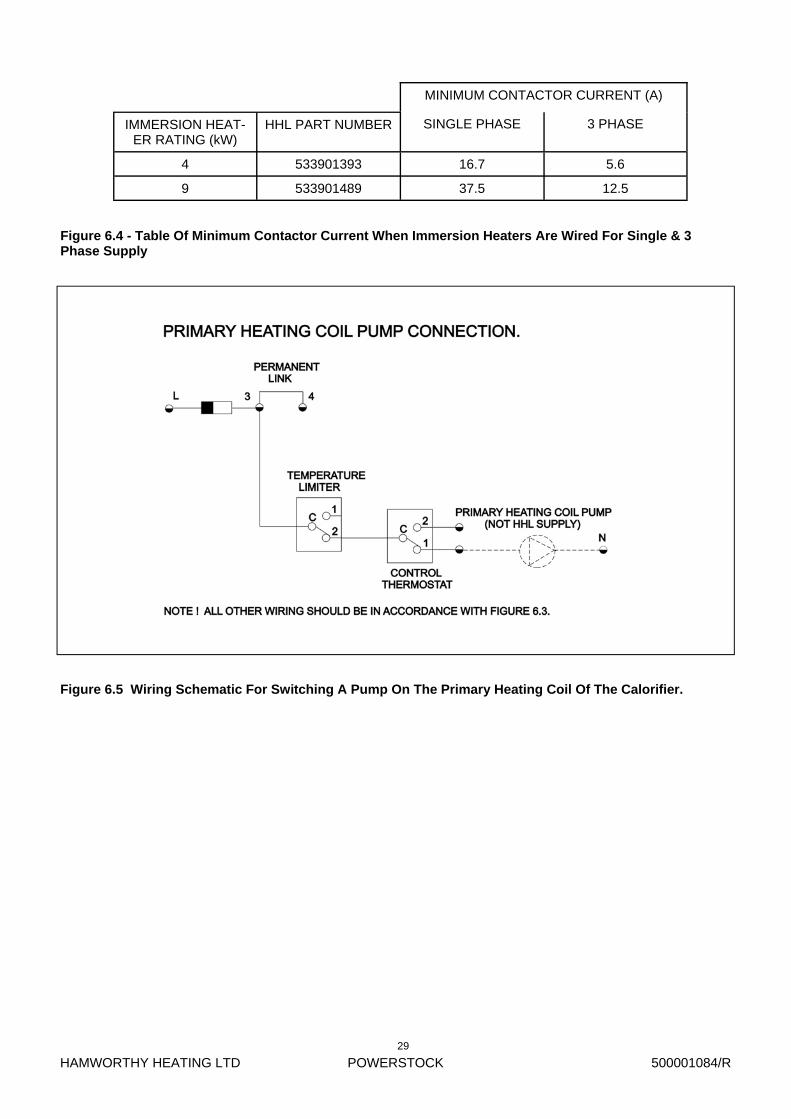
To ensure safe & efficient operation of the Powered Anode the following points need to be observed: 1) That the vessel is full of water before switching on the electrical supply. If everything is satisfactory, the lamp will glow green. The lamp will flash red as a warning if there is a problem. This indicates that the protection is not effective and one of the following has occurred. a) There is no water in the vessel. b) There is a short circuit between the anode and the vessel. c) The two-core cable to the anode has been connected the wrong way round. On rectification of faults above interrupting the mains electrical supply to the unit for a brief period (30 seconds) will reset the indicator lamp. 2) Time clocks, etc must NOT interrupt power to this circuit. To enable the powered anode system to provide continuous protection it must have a permanent power supply. 3) The powered anode must be switched off if the Powerstock water heater in which it is installed is to stand longer than 2 months undrained & without any draw off of water from the vessel. 4) Do not disconnect the anode from the potentio-stat by detaching the connecting cable to the anode if the storage water heater is full otherwise no protection will be provided against corrosion. 5) Before touching the impressed-current anode ,the electrical supply to any immersion heater in the tank must be disconnected, as mains voltage may be present on the impressed anode should the immersion heater be defective. Ensure periodic electrical checks of the immersion heater & impressed current anode by a specialist. 7.4.2 FLANGE KIT FOR IMMERSION ELEMENT. (see Figure No 9.2) A flange kit for an immersion element is available with fitting instructions. HHL Part No. 563605221 PS160-500 Models HHL Part No. 563605466 PS750-1000 Models Immersion elements below are supplied optionally 4kW x 280mm long, 240V a.c. Part No. 533901393 & 9kW x 280mm long , 240Vac. Part No. 533901489. NOTE: 1. Models PS160 and PS200 cannot have an immersion element fitted if the unit also has an unvented kit supplied. To meet the requirement of BS6700 and BS EN 806-2, it is recommended that where an immersion element is fitted on an unvented
system, the electrical supply to the immersion element should be connected to the manual reset limit thermostat of the vessel control panel in addition to the boiler, via suitable relays/contactors (not Hamworthy Heating Ltd supply ). This ensures that in the event of a high temperature condition occurring, both sources of energy will be safely shut down. See figure 6.3 for a schematic of an immersion heater wired to the control panel. See figure 6.4 for contactor current rating of the heater for single / 3 phase wiring. 7.4.3 TOP TO BOTTOM CIRCULATION. A top to bottom circulation kit can be supplied for each calorifier. (Refer to Figure No. 10.1). Where the internal coil of the heater is connected to a solar thermal heating system the circulation pump is only used during the daily legionella bacteria pasteurization cycle, as stratification in the tank is required. For applications where the primary coil of the vessel is connected to a boiler only the pump can be run continuously to ensure de-stratification of the calorifer contents. The kit is supplied for assembly to the calorifier when the calorifier is located in its final position. NOTE 1: The connection Tee’s must be fitted to the hot water flow and cold water return connections prior to any connection to the system pipework. NOTE 2: All jointing compound used should be approved suitable for potable water by WRAS. NOTE 3: Ensure flow arrows on the pump and check valve allow flow from the top to the bottom of the Calorifier. The pump will require connection to a 230Vac 50Hz electrical supply via a fused isolator using heat resisting 3 core cable of adequate rating (not HHL supply). Refer to pump manufacturer’s instructions for details of fuse sizing etc. WARNING: This pump must be earthed. 8.0 COMMISSIONING AND TESTING 8.1 Once all installation work has been completed the unit should be filled with water to check for leaks. For the calorifiers do this on both primary & secondary sides. Calorifiers should be thoroughly flushed through to remove debris from vessels / pipework, etc. Refer to section 5.0 WATER CIRCULATION GENERAL and the relevant standard or code of practice for correct procedure. The system should be chemically cleaned with an approved disinfectant before use. Switch on the boiler or heat source and ensure flow-rates are correct as per Figure No 1.2 Technical data.
HAMWORTHY HEATING LTD
POWERSTOCK
500001084/R
6
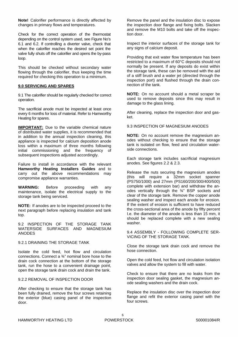
Note! Calorifier performance is directly affected by changes in primary flows and temperatures. Check for the correct operation of the thermostat depending on the control system used, see Figure No’s 6.1 and 6.2. If controlling a diverter valve, check that when the calorifier reaches the desired set point the valve fully shuts off the calorifier and opens the by-pass loop. This should be checked without secondary water flowing through the calorifier, thus keeping the time required for checking this operation to a minimum. 9.0 SERVICING AND SPARES 9.1 The calorifier should be regularly checked for correct operation. The sacrificial anode must be inspected at least once every 6 months for loss of material. Refer to Hamworthy Heating for spares. IMPORTANT: Due to the variable chemical nature of distributed water supplies, it is recommended that in addition to the annual inspection cleaning, this appliance is inspected for calcium deposition anode loss within a maximum of three months following initial commissioning and the frequency of subsequent inspections adjusted accordingly. Failure to install in accordance with the relevant Hamworthy Heating Installers Guides and to carry out the above recommendations may compromise appliance warranties. WARNING: Before proceeding with any maintenance, isolate the electrical supply to the storage tank being serviced. NOTE: If anodes are to be inspected proceed to the next paragraph before replacing insulation and tank top. 9.2 INSPECTION OF THE STORAGE TANK WATERSIDE SURFACES AND MAGNESIUM ANODES 9.2.1 DRAINING THE STORAGE TANK Isolate the cold feed, hot flow and circulation connections. Connect a ¾” nominal bore hose to the drain cock connection at the bottom of the storage tank, run the hose to a convenient drainage point, open the storage tank drain cock and drain the tank. 9.2.2 REMOVAL OF INSPECTION DOOR After checking to ensure that the storage tank has been fully drained, remove the four screws retaining the exterior (blue) casing panel of the inspection door.
Remove the panel and the insulation disc to expose the inspection door flange and fixing bolts. Slacken and remove the M10 bolts and take off the inspec-tion door. Inspect the interior surfaces of the storage tank for any signs of calcium deposit. Providing that exit water flow temperature has been restricted to a maximum of 60°C deposits should not normally be present. If any deposits do exist within the storage tank, these can be removed with the aid of a stiff brush and a water jet (directed through the inspection port) and flushed through the drain con-nection of the tank. NOTE: On no account should a metal scraper be used to remove deposits since this may result in damage to the glass lining. After cleaning, replace the inspection door and gas-ket. 9.3 INSPECTION OF MAGNESIUM ANODES NOTE: On no account remove the magnesium an-odes without checking to ensure that the storage tank is isolated on flow, feed and circulation water-side connections. Each storage tank includes sacrificial magnesium anodes. See figures 2.2 & 2.3. Release the nuts securing the magnesium anodes (this will require a 32mm socket spanner (PS750/1000) and 27mm (PS160/200/300/400/500) complete with extension bar) and withdraw the an-odes vertically through the ¾” BSP sockets and clear of the storage tank. Remove the copper anode sealing washer and inspect each anode for erosion. If the extent of erosion is sufficient to have reduced the cross-sectional area of the anode by fifty percent I.e. the diameter of the anode is less than 15 mm, it should be replaced complete with a new sealing washer. 9.4 ASSEMBLY - FOLLOWING COMPLETE SER-VICING OF THE STORAGE TANK. Close the storage tank drain cock and remove the hose connection. Open the cold feed, hot flow and circulation isolation valves and allow the system to fill with water. Check to ensure that there are no leaks from the inspection door sealing gasket, the magnesium an-ode sealing washers and the drain cock. Replace the insulation disc over the inspection door flange and refit the exterior casing panel with the four screws.
HAMWORTHY HEATING LTD
POWERSTOCK
500001084/R
7
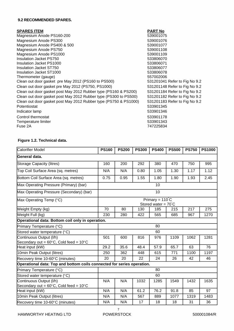
9.2 RECOMMENDED SPARES.
SPARES ITEM PART No Magnesium Anode PS160-200 539001075 Magnesium Anode PS300 Magnesium Anode PS400 & 500
539001076 539001077
Thermometer (gauge) 557002006 Clean out door gasket pre May 2012 (PS160 to PS500) 531201041 Refer to Fig No 9.2
Potentiostat 533901345 Indicator lamp 533901346
Control thermostat 533901178 Temperature limiter 533901343 Fuse 2A 747225834
Clean out door gasket pre May 2012 (PS750, PS1000) 531201148 Refer to Fig No 9.2
Magnesium Anode PS750 539001108 Magnesium Anode PS1000 539001109 Insulation Jacket PS750 533806070 Insulation Jacket PS1000 533806071 Insulation Jacket ST750 533806077 Insulation Jacket ST1000 533806078
Clean out door gasket post May 2012 Rubber type (PS160 & PS200) 531201184 Refer to Fig No 9.2 Clean out door gasket post May 2012 Rubber type (PS300 to PS500) 531201182 Refer to Fig No 9.2 Clean out door gasket post May 2012 Rubber type (PS750 & PS1000) 531201183 Refer to Fig No 9.2
Calorifier Model PS160 PS200 PS300 PS400 PS500 PS750 PS1000
General data.
Storage Capacity (litres) 160 200 292 380 470 750 995
Top Coil Surface Area (sq. metres) N/A N/A 0.80 1.05 1.30 1.17 1.12
Bottom Coil Surface Area (sq. metres) 0.75 0.95 1.55 1.80 1.90 1.93 2.45
Max Operating Pressure (Primary) (bar) 10
Max Operating Pressure (Secondary) (bar) 10
Max Operating Temp (C) Primary = 110°C Stored water = 70°C
Weight Empty (kg) 70 80 130 185 215 217 275
Weight Full (kg) 230 280 422 565 685 967 1270
Operational data: Bottom coil only in operation.
Primary Temperature (C) 80
Stored water temperature (C) 60
Continuous Output (l/h) Secondary out = 60C, Cold feed = 10C
501 600 816 976 1109 1062 1281
Heat input (kW) 29.2 35.6 48.4 57.9 65.7 63 76
10min Peak Output (litres) 250 362 448 615 771 1100 1197
Recovery time 10-60C (minutes) 20 20 22 24 26 42 46
Operational data: Top and bottom coils connected for series operation.
Primary Temperature (C) 80
Stored water temperature (C) 60
Continuous Output (l/h) Secondary out = 60C, Cold feed = 10C
N/A N/A 1032 1285 1549 1432 1635
Heat input (kW) N/A N/A 61.2 76.2 91.8 85 97
10min Peak Output (litres) N/A N/A 567 889 1077 1319 1483
Recovery time 10-60C (minutes) N/A N/A 17 18 18 31 36
Figure 1.2. Technical data.
HAMWORTHY HEATING LTD
POWERSTOCK
500001084/R
8
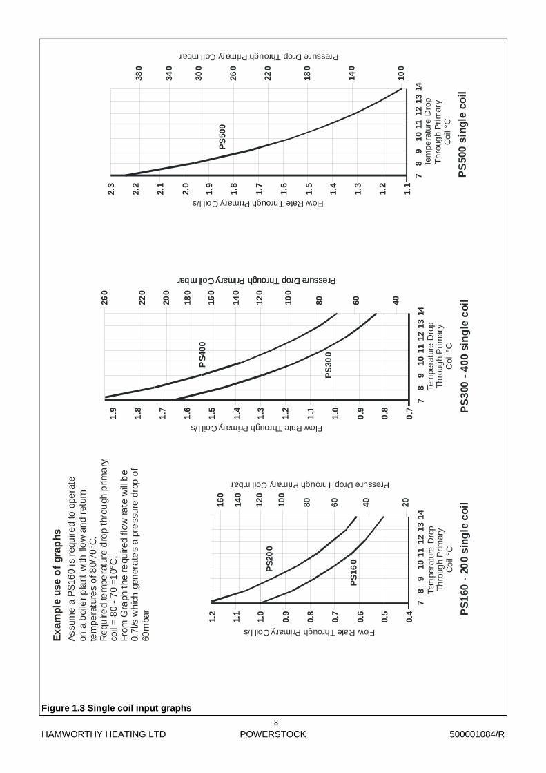
Figure 1.3 Single coil input graphs
40
14
PS
160
- 2
00
sin
gle
co
il
0.4
78
9
0.5
1210
1113
20
0.6
0.7
0.8
0.9
1.1
1.0
100
6080140
120
1.2
160
180
200
80 60120
140
100
160
40
10
PS
300
- 4
00
sin
gle
coi
l
0.7
79
8
0.8
1112
1314
1.2
0.9
1.0
1.1
1.3
1.4
1.5
1.7
1.6
PS
500
sin
gle
co
il
1.1
1.2
1.3
98
710
1113
1214
100
220
1.8
1.9
260
2.0
1.4
1.5
1.6
1.7
1.8
1.9
140
180
260
220
300
2.1
2.2
2.3
340
380
Tem
pera
ture
Dro
pT
hro
ugh
Prim
ary
Co
il °C
Tem
pera
ture
Dro
pT
hro
ugh
Pri
mar
yC
oil °
C
Tem
pera
ture
Dro
pT
hro
ugh
Pri
mar
yC
oil °
C
Flow Rate Through Primary Coil l/s
Flow Rate Through Primary Coil l/s
Flow Rate Through Primary Coil l/s
Pressure Drop Through Primary Coil mbar
Pressure Drop Through Primary Coil mbar Pressure Drop Through Primary Coil mbar
Pressure Drop Through Primary Coil mbar
PS
160
PS
200
PS
300
PS
400
PS
500
Ex
ampl
e us
e o
f gr
aphs
As
sum
e a
PS
160
is r
equ
ired
to o
pera
teon
a b
oile
r pla
nt w
ith fl
ow
an
d re
turn
tem
pera
ture
s o
f 80/
70°C
.R
equ
ired
tem
pera
ture
dro
p th
rou
gh p
rima
ryco
il =
80
- 7
0 =1
0°C
.Fr
om G
raph
the
requ
ired
flow
ra
te w
ill b
e0.
7l/s
wh
ich
gen
era
tes
a pr
ess
ure
dro
p o
f60
mba
r.
HAMWORTHY HEATING LTD
POWERSTOCK
500001084/R
9
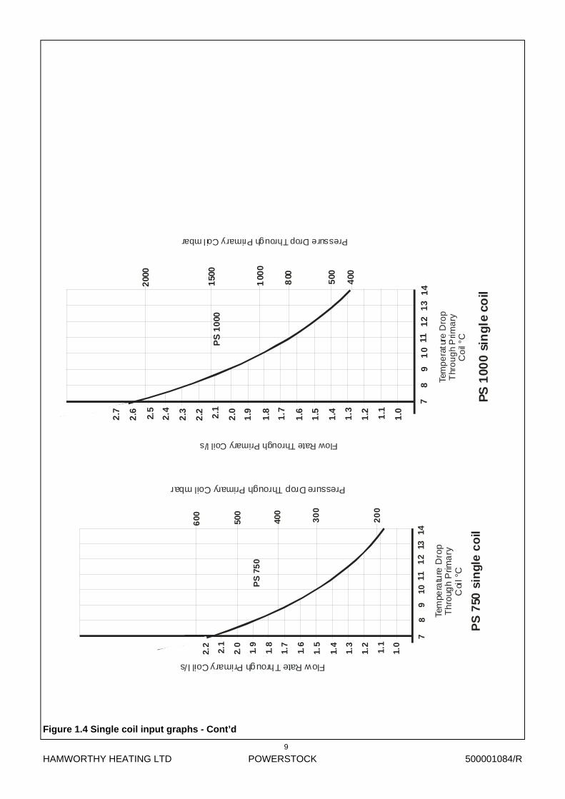
Figure 1.4 Single coil input graphs - Cont’d
Tem
pera
ture
Dro
pT
hro
ugh
Prim
ary
Coi
l °C
7
1.0
1.1
1.2
1.3
1.4
30
0
400
20
0
500
600
1.5
1.6
1.7
1.8
1.9
2.0
2.1
2.2
PS
75
0
PS
750
sin
gle
co
il
98
1014
131
211
Pressure Drop Through Primary Coil mbar
Flow Rate Through Primary Coil l/s
Flow Rate Through Primary Coil l/s
Pressure Drop Through Primary Coil mbar
Tem
pe
ratu
re D
rop
Thr
ou
gh
Prim
ary
Co
il °C
7
1.01.1
1.2
1.3
1.4
800
400
500
100
0
150
0
200
0
1.5
1.61.7
1.8
1.9
2.02.1
2.2
PS
10
00
PS
100
0 si
ng
le c
oil
2.32.5
2.4
2.62.7
98
10
111
21
31
4
HAMWORTHY HEATING LTD
POWERSTOCK
500001084/R
10
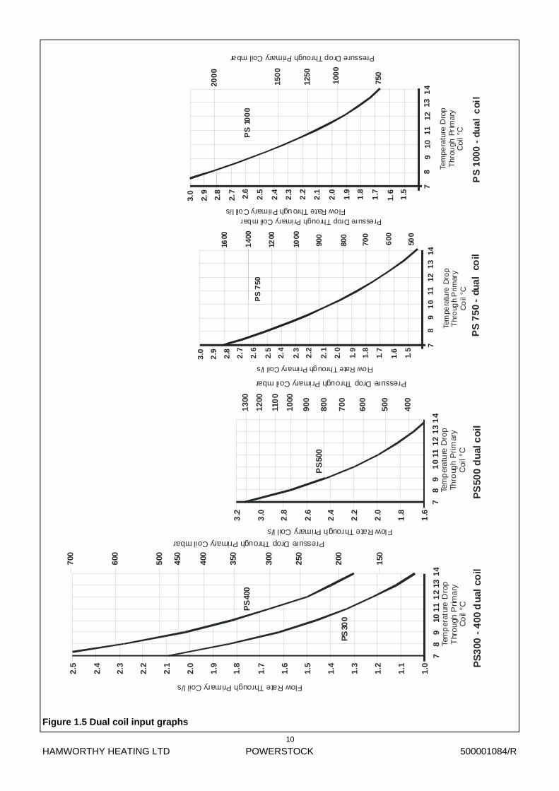
Figure 1.5 Dual coil input graphs
PS
500
du
al c
oil
98
71
011
13
12
14
2.4
1.6
1.8
2.0
2.2
2.6
2.8
3.0
60
0
3.2
40
0
50
0
70
0
80
0
90
0
10
00
110
0
12
00
13
00
2.1 P
S3
00 -
400
du
al c
oil
1.0
1.1
1.2
11
109
87
14
131
2
150
1.3
1.4
1.5
1.6
200
250
1.9
1.7
1.8
2.0
350
450
300
400
2.2
2.3
2.4
500
600
2.5
700
Tem
per
atur
e D
rop
Thr
ou
gh P
rima
ryC
oil
°C
Tem
per
atu
re D
rop
Thro
ugh
Pri
mar
yC
oil °
C
Flow Rate Through Primary Coil l/s
Flow Rate Through Primary Coil l/s
Pressure Drop Through Primary Coil mbar
Pressure Drop Through Primary Coil mbar
PS
300
PS
400
PS
500
Flow Rate Through Primary Coil l/s
Pressure Drop Through Primary Coil mbar
Tem
pera
ture
Dro
pT
hro
ugh
Prim
ary
Co
il °C
7
1.5
1.6
1.7
1.8
1.9
800
1000
1200
500
600
700
900
140
0
1600
2.0
2.1
2.2
2.3
2.4
2.5
2.6
2.9 2.7
3.0 2.8
PS
750
PS
75
0 -
dua
l c
oil
98
10
1112
13
14
Flow Rate Through Primary Coil l/s
Tem
pera
ture
Dro
pT
hrou
gh P
rim
ary
Coi
l °C
7
1.5
1.6
1.7
1.8
1.9
100
0
150
0
200
0
750
1250
2.0
2.1
2.2
2.3
2.4
2.52.6
2.9
2.7
3.0
2.8
PS
10
00
PS
100
0 -
du
al
co
il
98
1011
1213
14
Pressure Drop Through Primary Coil mbar
HAMWORTHY HEATING LTD
POWERSTOCK
500001084/R
11
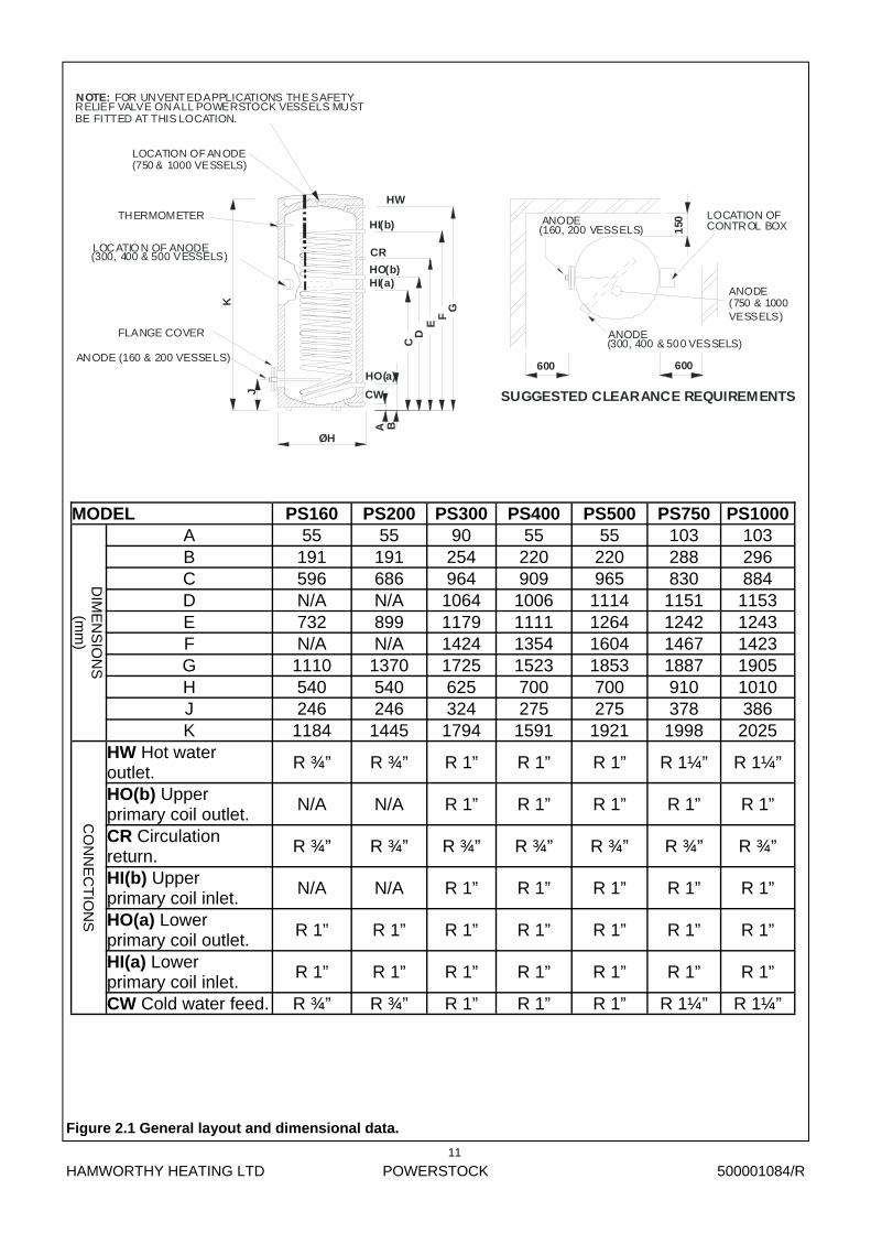
PS160 PS200 PS300 PS400 PS500
DIM
EN
SIO
NS
(m
m)
A 55 55 90 55 55 B 191 191 254 220 220 C 596 686 964 909 965 D N/A N/A 1064 1006 1114 E 732 899 1179 1111 1264 F N/A N/A 1424 1354 1604 G 1110 1370 1725 1523 1853 H 540 540 625 700 700 J 246 246 324 275 275 K 1184 1445 1794 1591 1921
CO
NN
EC
TIO
NS
HW Hot water outlet.
R ¾” R ¾” R 1” R 1” R 1”
HO(b) Upper primary coil outlet.
N/A N/A R 1” R 1” R 1”
CR Circulation return.
R ¾” R ¾” R ¾” R ¾” R ¾”
HI(b) Upper primary coil inlet.
N/A N/A R 1” R 1” R 1”
HO(a) Lower primary coil outlet.
R 1” R 1” R 1” R 1” R 1”
HI(a) Lower primary coil inlet.
R 1” R 1” R 1” R 1” R 1”
CW Cold water feed. R ¾” R ¾” R 1” R 1” R 1”
MODEL PS750 103 288 830
1151 1242 1467 1887 910 378
1998
R 1¼”
R 1”
R ¾”
R 1”
R 1”
R 1”
R 1¼”
PS1000 103 296 884
1153 1243 1423 1905 1010 386
2025
R 1¼”
R 1”
R ¾”
R 1”
R 1”
R 1”
R 1¼”
Figure 2.1 General layout and dimensional data.
EF
CR
C
K
J
FLANGE COVER
A
ØH
BCW
HO(a)
THERMOMETER
HI(a)HO(b)
HI(b)
D
G
ANODE (160 & 200 VESSELS)
HW
150
600
LOCATION OF ANODE(300, 400 & 500 VESSELS)
ANODE(300, 400 & 500 VESSELS)
SUGGESTED CLEARANCE REQUIREMENTS
(160, 200 VESSELS)ANODE LOCATION OF
CONTROL BOX
600
NOTE: FOR UNVENT ED APPLICATIONS THE SAFETYRELIEF VALVE ON ALL POWERSTOCK VESSELS MUSTBE FITTED AT THIS LOCATION.
LOCATION OF ANODE(750 & 1000 VESSELS)
ANODE(750 & 1000VESSELS)
HAMWORTHY HEATING LTD
POWERSTOCK
500001084/R
12
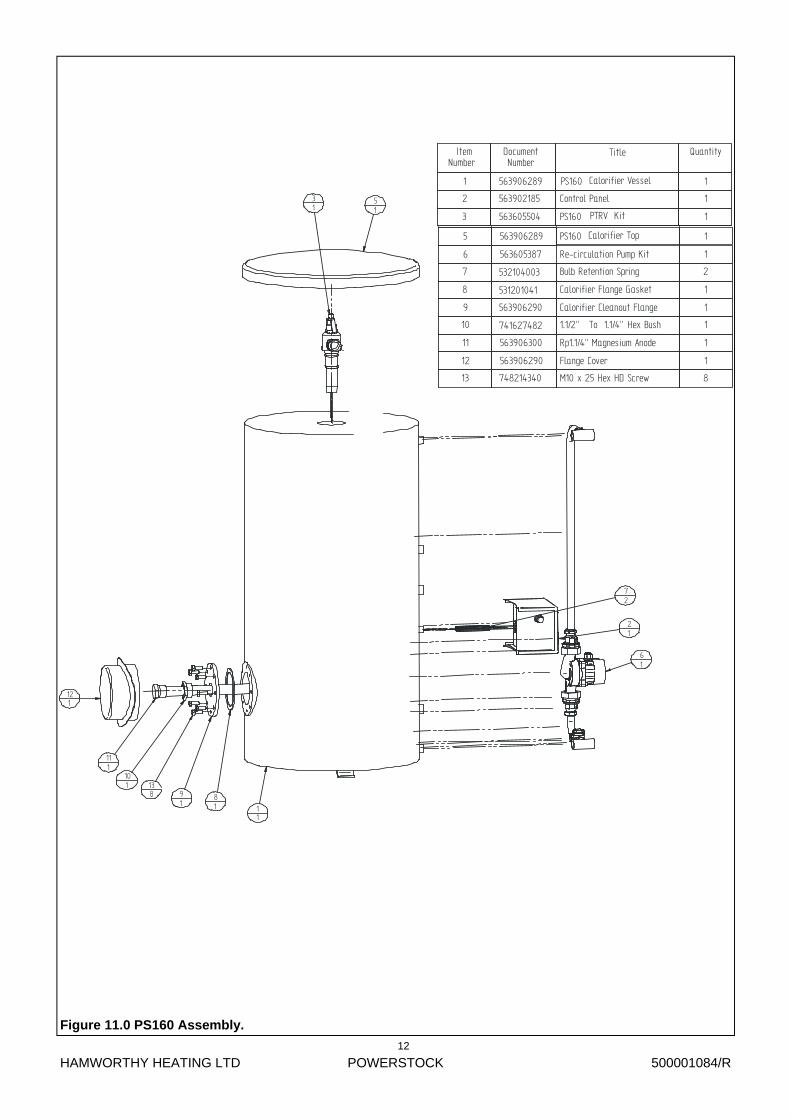
Figure 11.0 PS160 Assembly.
61
31
21
51
11
101
121
81
91
111
72
138
ItemNumber
DocumentNumber
Title Quantity
1 563906289 Calorifier Vessel 1
2 563902185 Control Panel 1
3 563605504
PS160
PTRV Kit 1
5 563906289 PS160 Calorifier Top 1
6 563605387 Re-circulation Pump Kit 1
7 532104003 Bulb Retention Spring 2
8 531201041 Calorifier Flange Gasket 1
9 563906290 Calorifier Cleanout Flange 1
10 741627482 1.1/2" To 1.1/4” Hex Bush 1
11 563906300 Rp1.1/4” Magnesium Anode 1
12 563906290 Flange Cover 1
13 748214340 M10 x 25 Hex HD Screw 8
PS160
HAMWORTHY HEATING LTD
POWERSTOCK
500001084/R
13
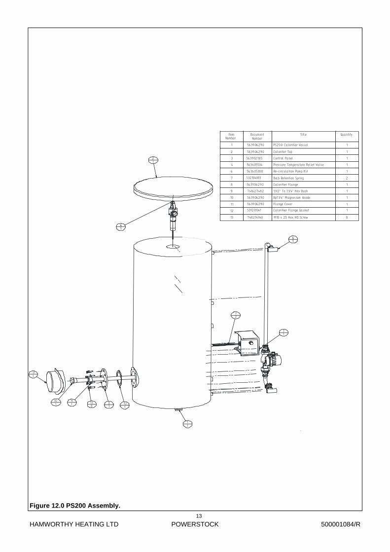
Figure 12.0 PS200 Assembly.
61
41
31
91
111
121
81
21
11
101
72
138
ItemNumber
DocumentNumber
Title Quantity
1 563906290 PS200 1
2 563906290 Calorifer Top 1
3 563902185 Control Panel 1
4 563605504 Pressure Temperature Relief Valve 1
6
532104003
Re-circulation Pump Kit 1
7 Bulb Retention Spring 2
8 563906290
Calorifier Vessel
1
9 741627482 1.1/2" To 1.1/4” Hex Bush 1
10
563906290
Calorifier Flange Gasket 1
11 1
12
13 748214340 M10 x 25 Hex HD Screw 8
563605388
531201041
Rp1.1/4” Magnesium Anode 1563906290
Flange Cover
Calorifier Flange

HAMWORTHY HEATING LTD
POWERSTOCK
500001084/R
14
Figure 13.0 PS300 Assembly With Impressed Current Anode & Immersion Heater.
91
131
141
31
51
41
81
111
21
11
121
71
108
Item DocumentNumber
Title Quantity
1 563906291
Recirculation Pump Kit
1
2 563906291 1
3 563605389 1
4 563902185 Control Panel 1
5 563605507 PTRV Kit 1
7 741627482 1.1/2” To 1.1/4”Hex Bush 1
8 531201041 Calorifier Flange Gasket 1
9 530501014 Flange Adaptor For Immersion Element 1
10 748214365 Hexagon Head Screw ISO4017 - M10x35 8
11 563906291 Flange Cover 1
12 741627340 Hex. Bush Male R1.1/4”x Female Rc1” 1
13 533901347 Impressed Current Electrode 1
14 533901489 9kW Immersion Element 1
Number
Calorifier VesselCalorifier Top

HAMWORTHY HEATING LTD
POWERSTOCK
500001084/R
15
Figure 14.0 PS400 Assembly.
161
91
81
31
41
21
11
61
51
141
111
121
151
102
138
Item DocumentNumber
Title Quantity
1 563906292 PS400 Calorifier Vessel 12 563906292 PS400 Calorifier Top 13 563905508 Pressure Temperature Relief Valve Kit 14 563902185 Control Panel 15 741627482 1.1/2” TO 1.1/4” BSPT Hex Bush 16 563906292 1” BSPT Bronze Plug 18 563605390 Re-circulation pump kit 19 563605174 Series Flow Coupling Kit 110 532104003 Bulb Retention Spring 211 531201041 Cleanout Flange Gasket 112 563906292 Cleanout Flange 113 748214340 M10x25 Hex HD Screw 814 563906292 Flange Cover 115 563906292 1.1/4” BSPP Magnesium Anode 116 557002006 Thermometer 1
HAMWORTHY HEATING LTD
POWERSTOCK
500001084/R
16
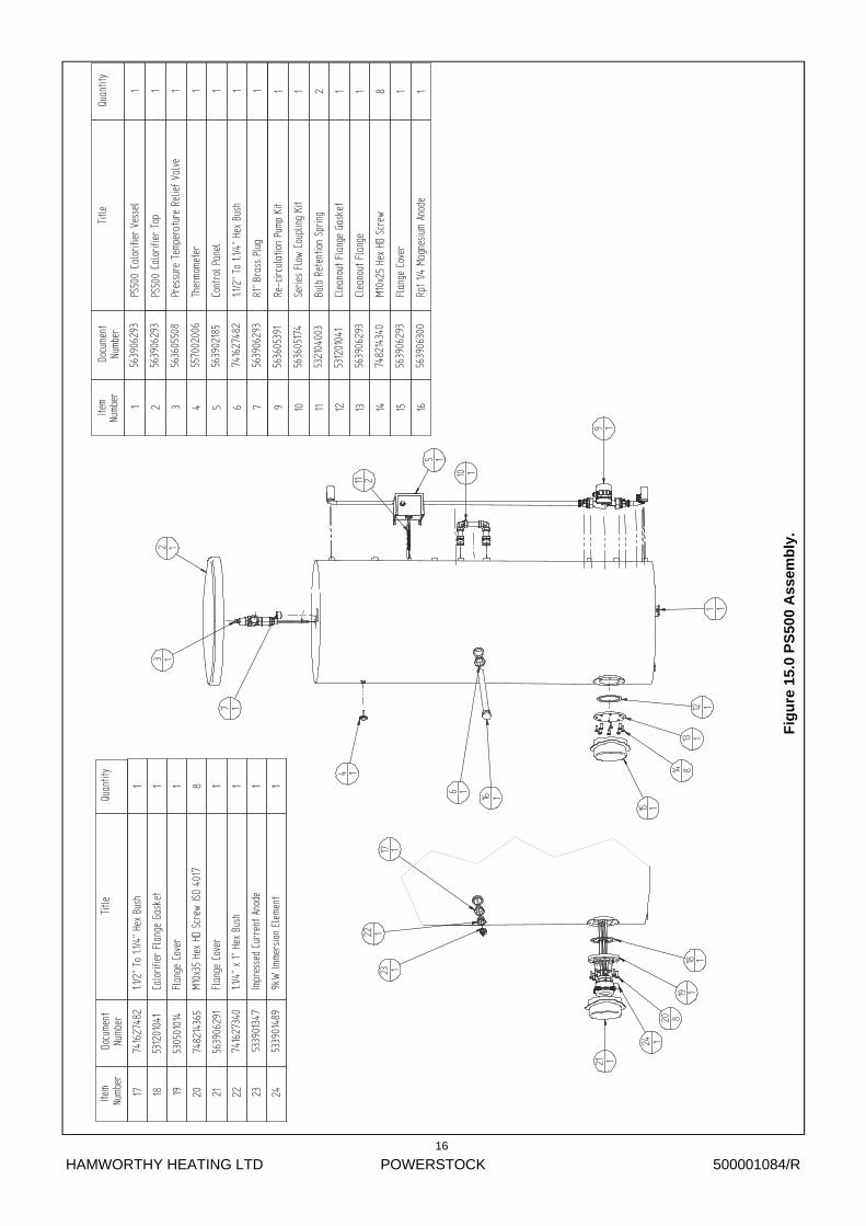
Fig
ure
15.
0 P
S50
0 A
ssem
bly
.
10 1
9 1
3 1
5 1
7 1
6 1
15 1
12 1
13 1
16 1
11 2
4 1
2 1
1 1
14 819 1
17 1
24 1
18 1
21 1
23 1
22 1
20 8
Numb
erDo
cume
ntNu
mber
Title
Quan
tity
1774
1627
482
1.1/2
” To
1.1/
4” H
ex B
ush
1
1853
1201
041
Calo
rifie
r Fl
ange
Gas
ket
1
1953
0501
014
Flan
ge C
over
1
2074
8214
365
M10x
35 H
ex H
D Sc
rew
ISO
4017
8
2156
3906
291
Flan
ge C
over
1
22 7
4162
7340
1.1/4
” x
1” H
ex B
ush
1
2353
3901
347
Impr
esse
d Cu
rren
t An
ode
1
2453
3901
489
9kW
Imme
rsio
n El
emen
t1
Item
Item
Docu
ment
Nu
mber
Title
Quan
tity
156
3906
293
PS50
0Ca
lorif
ier
Vess
el1
256
3906
293
Calo
rifie
r To
p1
356
3605
508
Pres
sure
Tem
pera
ture
Rel
ief
Valv
e1
455
7002
006
Ther
mome
ter
1
556
3902
185
Cont
rol P
anel
1
674
1627
482
1.1/2
” To
1.1/
4” H
ex B
ush
1
756
3906
293
R1”
Bras
s Pl
ug1
956
3605
391
Re-c
ircul
atio
n Pu
mp K
it1
1056
3605
174
Serie
s Fl
ow C
oupl
ing
Kit
1
1153
2104
003
Bulb
Ret
entio
n Sp
ring
2
1253
1201
041
Clea
nout
Fla
nge
Gask
et1
1356
3906
293
Clea
nout
Fla
nge
1
1474
8214
340
M10x
25 H
ex H
D Sc
rew
8
1556
3906
293
Flan
ge C
over
1
1656
3906
300
Rp1
1/4 M
agne
sium
Anod
e1
PS50
0
Numb
er

HAMWORTHY HEATING LTD
POWERSTOCK
500001084/R
17
Fig
ure 16.0 P
S750 A
ssemb
ly.
141
21
31
101 181
191
121131
6141
72
15111
51
91
171 81
1610
REMOVE & PLUG WITH 742227223
IF IMPRESSED ANODE IS USED
DETAIL A
201
ItemNumber
DocumentNumber
TitleQuantity
1563906294
PS750CALORIFIER
VESSEL1
2533806070
PS750CALORIFIER
JACKET1
3533806070
PS750CALORIFIER
TOP1
4563905464
PS750UNVENTED
SYSTEM1
5563906300
Rp11/4MAGNESIUM
ANODE1
6563605492
PS750CONTROL
PANELKIT
1
7532104003
BULBRETENTION
SPRING2
8741627482
1.1/2"TO1.1/4"HEX
BUSH1
9557002006
THERMOMETER1
10533806078
PS-ST1000FLANGE
COVER1
12563605460
RE-CIRCULATIONPUMP
KITPS750
1
13563605489
SERIESFLOW
COUPLINGKIT
PS750/PS10001
14530501014
FLANGEADAPTOR
FORIMMERSION
ELEMENT1
15531201148
PS750/1000FLANGE
GASKET1
16748214340
M10x
25HEX
HDSCREW
10
17741627340
HEX.BUSHM
ALER11/4"
xFEMALE
Rc1"REDUCING
1
18533901347
IMPRESSEDCURRENT
ELECTRODE1
19533901489
9kWIMMERSION
ELEMENT1
20*742227082
11/2"
TAPERPLUG
1
HAMWORTHY HEATING LTD
POWERSTOCK
500001084/R
18
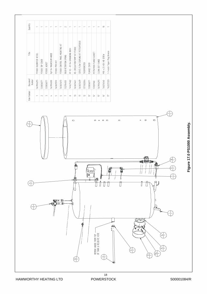
Fig
ure
17.
0 P
S10
00 A
ssem
bly
.
3 1
2 1
10 111 1
6 15 1
8 1
1 17 2
12 1
4 1
REMO
VE A
NODE
FRO
M TO
P OF
TAN
K &
RELO
CATE
HER
E
13 1
14 115 1
6 1
Item
Numb
erDo
cume
ntNu
mber
Title
Quan
tity
156
3906
295
PS10
00CA
LORI
FIER
VESS
EL1
253
3806
071
PS10
00TO
PCO
VER
1
353
3806
071
PS10
00JA
CKET
1
456
3906
300
Rp11
/4MA
GNES
IUM
ANOD
E1
556
3605
510
PS10
00PT
RVKI
T1
656
3605
493
PS10
00CO
NTRO
LPA
NEL
MOUN
TING
KIT
1
753
2104
003
BULB
RETE
NTIO
NSP
RING
2
874
1627
482
R11/2
-R1
1/4GR
OUND
ING
BUSH
1
1056
3605
461
RE-C
IRCU
LATI
ONPU
MPKI
TPS
1000
1
1156
3605
489
SERI
ESFL
OWCO
UPLIN
GKI
TPS
750/
PS10
001
1255
7002
006
THER
MOME
TER
1
13*
5338
0607
1FL
ANGE
COVE
R1
14*
5312
0114
8PS
750/
1000
FLAN
GEGA
SKET
1
15*
5639
0629
5CL
EAN-
OUT
FLAN
GE1
16*
7482
1434
0M1
0x
25HE
XHD
SCRE
W10
17*
7422
2722
31-
1-4i
nch
Tape
rPl
ugBr
onze
1
HAMWORTHY HEATING LTD
POWERSTOCK
500001084/R
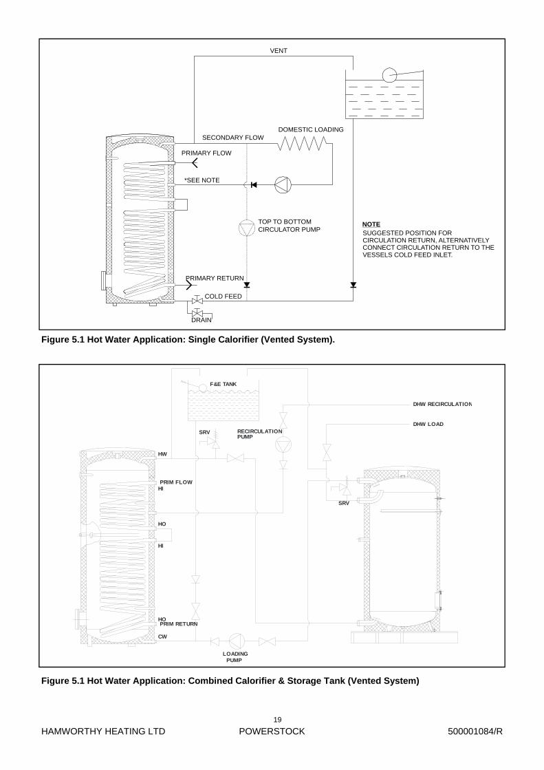
19
SECONDARY FLOW
PRIMARY FLOW
PRIMARY RETURN
COLD FEED
DRAIN
DOMESTIC LOADING
VENT
TOP TO BOTTOMCIRCULATOR PUMP
*SEE NOTE
SUGGESTED POSITION FORCIRCULATION RETURN, ALTERNATIVELYCONNECT CIRCULATION RETURN TO THEVESSELS COLD FEED INLET.
NOTE
Figure 5.1 Hot Water Application: Single Calorifier (Vented System).
Figure 5.1 Hot Water Application: Combined Calorifier & Storage Tank (Vented System)
CW
HO
HI
HO
HI
HW
F&E TANK
RECIRCULATIONPUMP
DHW RECIRCULATION
DHW LOAD
SRV
SRV
LOADINGPUMP
PRIM FLOW
PRIM RETURN
HAMWORTHY HEATING LTD
POWERSTOCK
500001084/R
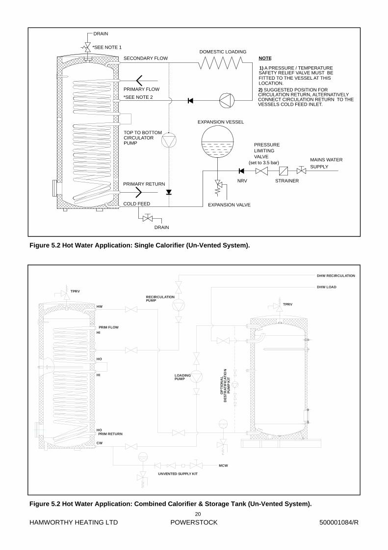
20
MAINS WATER
SUPPLY
EXPANSION VESSEL
NRV
EXPANSION VALVE
STRAINER
PRESSURELIMITINGVALVE
(set to 3.5 bar)
COLD FEED
DRAIN
PRIMARY RETURN
SECONDARY FLOW
PRIMARY FLOW
DOMESTIC LOADING*SEE NOTE 1
DRAIN
NOTE
1) A PRESSURE / TEMPERATURESAFETY RELIEF VALVE MUST BEFITTED TO THE VESSEL AT THISLOCATION.
SUGGESTED POSITION FOR2)CIRCULATION RETURN, ALTERNATIVELYCONNECT CIRCULATION RETURN TO THEVESSELS COLD FEED INLET.
*SEE NOTE 2
TOP TO BOTTOMCIRCULATORPUMP
Figure 5.2 Hot Water Application: Single Calorifier (Un-Vented System).
Figure 5.2 Hot Water Application: Combined Calorifier & Storage Tank (Un-Vented System).
CW
HO
HI
HO
HI
HW
MCW
PRIM FLOW
PRIM RETURN
DHW RECIRCULATION
DHW LOADTPRV
TPRV
RECIRCULATIONPUMP
LOADINGPUMP
UNVENTED SUPPLY KIT
OP
TIO
NA
L
PU
MP
KIT
DE
ST
RA
TIF
ICA
TIO
N
HAMWORTHY HEATING LTD
POWERSTOCK
500001084/R
21
EXPANSION VESSEL
EXPANSION VALVE
NRV
(set to 3.5 bar)
STRAINER
LIMITINGPRESSURE
VALVE
SUPPLYMAINS WATER
COLD WATERBOOSTERPUMP SET
COLD FEED
DRAIN
PRIMARY RETURN
SECONDARY FLOW
PRIMARY FLOW
DOMESTIC LOADING
*SEE NOTE 2
DRAIN
NOTE
*SEE NOTE 1
1) A PRESSURE / TEMPERATURESAFETY RELIEF VALVE MUST BEFITTED TO THE VESSEL AT THISLOCATION.
SUGGESTED POSITION FOR 2)CIRCULATION RETURN, ALTERNATIVELYCONNECT CIRCULATION RETURN TO THE VESSELS COLD FEED INLET.
TOP TO BOTTOMCIRCULATORPUMP
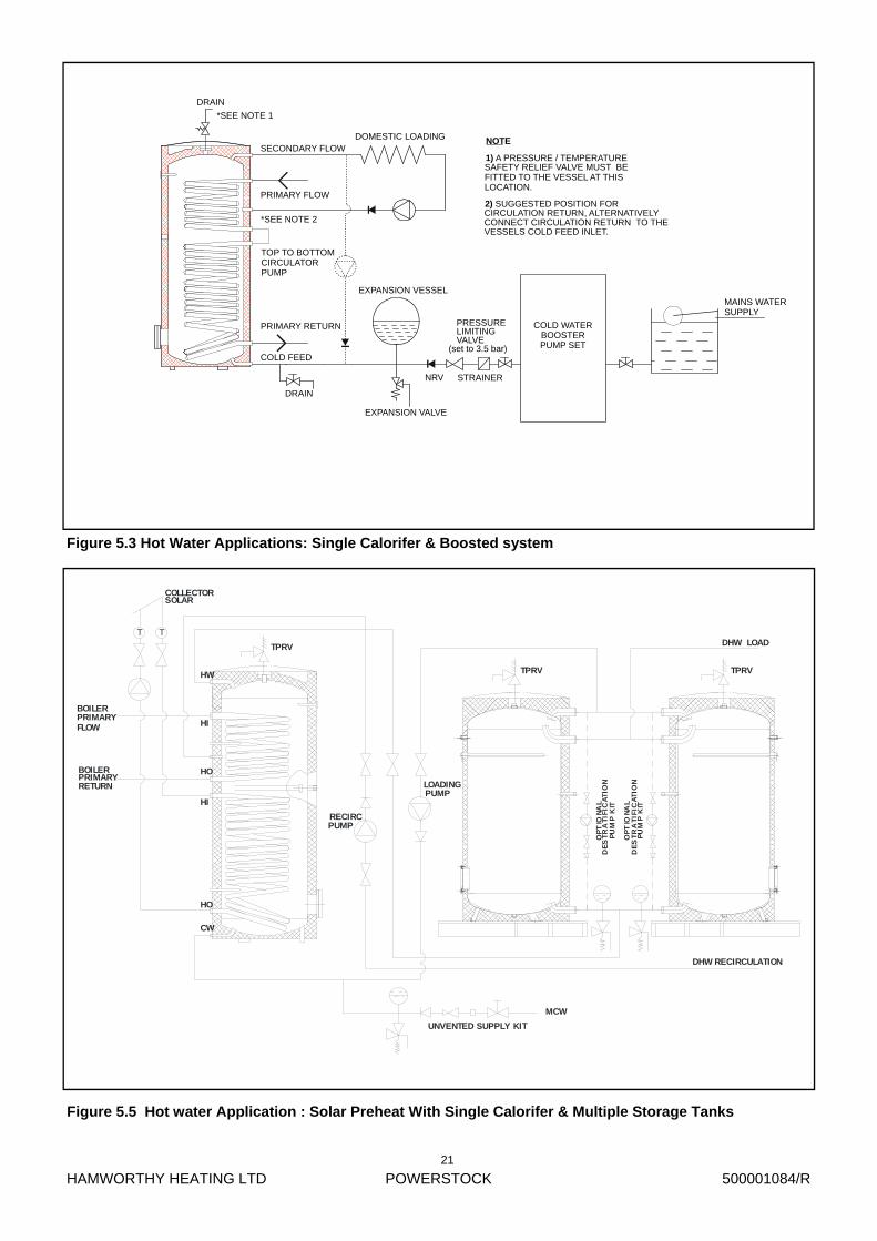
Figure 5.3 Hot Water Applications: Single Calorifer & Boosted system
Figure 5.5 Hot water Application : Solar Preheat With Single Calorifer & Multiple Storage Tanks
CW
HO
HI
HO
HI
HW
T T
SOLARCOLLECTOR
BOILERPRIMARYFLOW
BOILERPRIMARYRETURN
TPRV
TPRV TPRV
RECIRCPUMP
LOADINGPUMP
UNVENTED SUPPLY KIT
OP
TIO
NA
L
PU
MP
KIT
DE
ST
RA
TIF
ICA
TIO
N
OP
TIO
NA
L
PU
MP
KIT
DE
ST
RA
TIF
ICA
TIO
N
DHW RECIRCULATION
DHW LOAD
MCW
HAMWORTHY HEATING LTD
POWERSTOCK
500001084/R
22
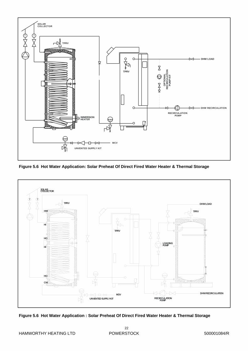
Figure 5.6 Hot Water Application: Solar Preheat Of Direct Fired Water Heater & Thermal Storage
Figure 5.6 Hot Water Application : Solar Preheat Of Direct Fired Water Heater & Thermal Storage
CW
HO
HI
HO
HI
HW
TPRV
SOLARCOLLECTOR
T T
TPRV
MGV
LOADINGPUMP
RECIRCULATIONPUMP
DHW LOAD
DHW RECIRCULATION
TPRV
UNVENTED SUPPLY KIT
MCV
O
PT
ION
AL
RE
CIR
CU
LATI
ON
P
UM
P K
IT
T T
TPRV
COLLECTOR
UNVENTED SUPPLY KIT
SOLAR
TPRV
HEATERIMMERSION
DHW LOAD
DHW RECIRCULATION
RECIRCULATION PUMP
HAMWORTHY HEATING LTD
POWERSTOCK
500001084/R
23
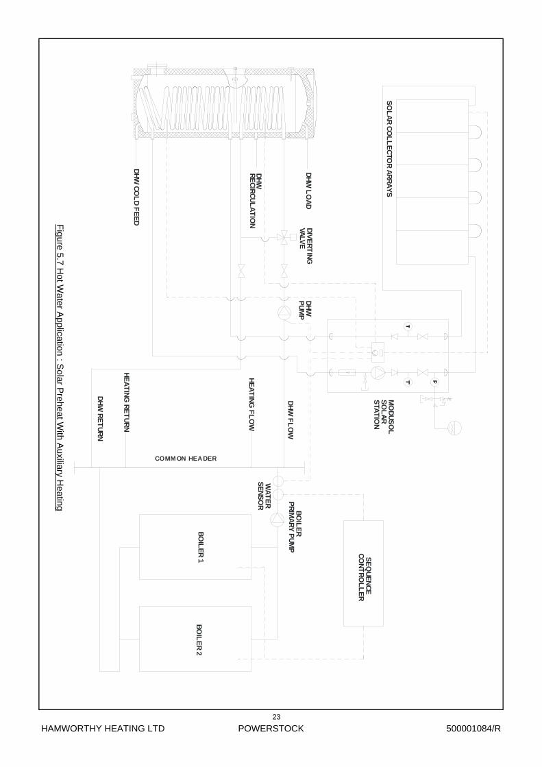
Figure 5.7 H
ot Water A
pplication : Sola
r Preheat W
ith Auxiliary H
eating
SO
LA
R C
OL
LE
CTO
R A
RR
AY
SM
OD
US
OL
STA
TIO
NS
OL
AR
DH
W L
OA
DD
IVE
RT
ING
VA
LVE
DH
WP
UM
P
DH
W C
OL
D F
EE
D
DH
WR
EC
IRC
UL
AT
ION
DH
W F
LO
W
DH
W R
ET
UR
N
HE
AT
ING
FL
OW
HE
AT
ING
RE
TU
RN
SE
QU
EN
CE
C
ON
TR
OL
LE
R
BO
ILE
RP
RIM
AR
Y P
UM
P
WA
TE
RS
EN
SO
R
COMM ON HEADER
BO
ILE
R 1
BO
ILE
R 2
HAMWORTHY HEATING LTD
POWERSTOCK
500001084/R
24
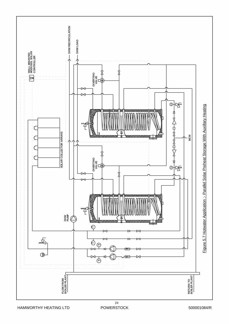
Fig
ure
5.7
Hot
wat
er A
pplic
atio
n :-
Par
alle
l Sol
ar P
rehe
at S
tora
ge W
ith A
uxill
ary
Hea
ting
RE
TU
RN
TO
BO
ILE
R P
LA
NT
T
SO
LA
R C
OL
LE
CT
OR
AR
RA
YS
TT
T
FL
OW
FR
OM
BO
ILE
R P
LA
NT
DIV
ER
TIN
G
VA
LV
E
DH
WP
UM
P
MC
W
WA
LL
MO
UN
TE
DM
OD
US
OL
SO
LA
RC
ON
TR
OL
LE
R
DIV
ER
TIN
G
VA
LV
E
DH
W L
OA
D
DH
W R
EC
IRC
UL
AT
ION

HAMWORTHY HEATING LTD
POWERSTOCK
500001084/R
Figure 7.4 Earth tag assembly.
Figure 7.3 Control box layout.
MOUNTING PLATE(DETACHABLE)
TEMPE RATURELIMITE R
CONTROLTHERMOSTAT
LOCATION OF POWEREDANODE P OTENTIOS TATBE LOW DETACHA BLEPLATE IF FITTED.
LOCATION OF POWEREDANODE LAMP
(IF FITTED)
AFFIX CONTROL BOXTO THE UPP ERMOSTTHERMOSTAT POCKET.
AFFIX CONTROL BOXOVER THETHERMOSTAT POCKET.
POWE RSTOCK MODELS Ps300, 400 AND 500.
CONTROL BOXMOUNTINGBOSS
POWERSTO CK MODELS Ps160 , AND 200.
AFFIX CONTROL BOXTO PI LLARS ON MOUNTING BRACKETUSING SCREWS PROVIDE D.
POWERSTOCK MODEL S Ps750 AND 1000 .
CONTROL BOXMOUNTINGBRA CKET
BRACKET FIXED TOPIPE STUBS USINGCIRCLIPS PROVIDED
CONTROL BOX TOBE POSITIONEDAS SHOWN
THERMOSTAT BULBSASSEMBLED WITH‘W-CLIP ’ IN POCKET
SITE INSTALLEDPIPEWORK.
JUBILEE CLIP
EARTHCRIMP
POTENTIOSTATLEAD
COLD WATERFEED PIPE
25

HAMWORTHY HEATING LTD
POWERSTOCK
500001084/R
Figure 6.1 : Storage Tank Control Box Fascia.
Control Thermostat Temperature Adjustment Dial
Fuse Holder
Safety Limit Thermostat Reset Button (To Operate Remove Dust Cap)
Powered Anode Indication Light (Anode Fitted As Optional Extra)
26
Figure 6.2 : Schematic wiring diagram of the control box.
HAMWORTHY HEATING LTD
POWERSTOCK
500001084/R
27
Figure 6.2 Typical wiring of a Powerstock calorifier to a boiler.

HAMWORTHY HEATING LTD
POWERSTOCK
500001084/R
28
Figure 6.3 Typical Immersion Heater Control System For A Powerstock Calorifier.
HAMWORTHY HEATING LTD
POWERSTOCK
500001084/R
Figure 6.4 - Table Of Minimum Contactor Current When Immersion Heaters Are Wired For Single & 3 Phase Supply
IMMERSION HEAT-ER RATING (kW)
HHL PART NUMBER SINGLE PHASE 3 PHASE
4 533901393 16.7 5.6
9 533901489 37.5 12.5
MINIMUM CONTACTOR CURRENT (A)
Figure 6.5 Wiring Schematic For Switching A Pump On The Primary Heating Coil Of The Calorifier.
29
HAMWORTHY HEATING LTD
POWERSTOCK
500001084/R
30
Screw the M8 nutonto the shank ofthe foot plate.
Screw the foot intothe mounting platelocated on the baseof the vessel.
Level the vesseland lock the footinto position bytightening the M8nut.
Note: This operation to be carried out at three locations.
Figure 7.1 Leveling feet assembly
Figure 7.2.1 Coil connection (series flow) kit
75
DIM
EN
SIO
N
A
VESSEL3004005007501000
DIMENSION A6464114286234
UPPER PRIMARY COIL OUTLET
LOWER PRIMARY COIL INLET
CU
T
TO
LE
NG
TH
CUT TO LENGTH
HAMWORTHY HEATING LTD
POWERSTOCK
500001084/R
31
1” CORE MANIFOLDWITH INTEGRALNON RETURN VALVE.
1” BSP MAY BE USED FORCOLD WATER DRAW OFF IF REQUIRED.
1” PRESSURE LIMITING VALVEWITH INTEGRAL STRAINER.
3/4" BSP TAKE OFF TOEXPANSION VESSEL
¾" EXPANSION RELIEF VALVE
260
Powerstock model PS160 PS200 PS300 PS400 PS500 PS750 PS1000 Cold water feed side
Pressure limiting valve (set to 3.5 bar) with integral strainer.
HHL PART No 531902006
Expansion relief valve (set to 5 bar)
HHL PART No 531905003
Check valve HHL PART No 531911030
Expansion vessel - ‘Burstock’ range Part No.
25 litre 563605641
25 litre 563605641
25 litre x 2 563605641
25 litre x 2 563605641
60 litre 532712085
80 litre 532712086
100 litre 532712087
Secondary hot water side Pressure temperature relief valve (set to 7 bar and 90°C +5 –0)
HHL PART No 531905004
1¼” Female Socket (Bronze)
Not required
Not required
Not required
Not required
Not required
741620345 1 off
741620345 1 off
1¼” to 1” Reducing Nipple (Bronze)
Not required
Not required
Not required
Not required
Not required
741617250 1 off
741617250 1 off
Figure No 7.2.3 Unvented applications
NOTE: ON PS750 AND PS1000 MODELS 1” TO 1¼” NIPPLE AND 1¼” SOCKET SUPPLIED TO BE USED TO INCREASE PORT SIZE.
For PS160 to PS500 models quote HHL Ref: 562403076 For PS750 to PS1000 models quote HHL Ref: 562403214
Note : 25 litre expansion vessels are supplied complete with wall mounting bracket
HAMWORTHY HEATING LTD
POWERSTOCK
500001084/R
32
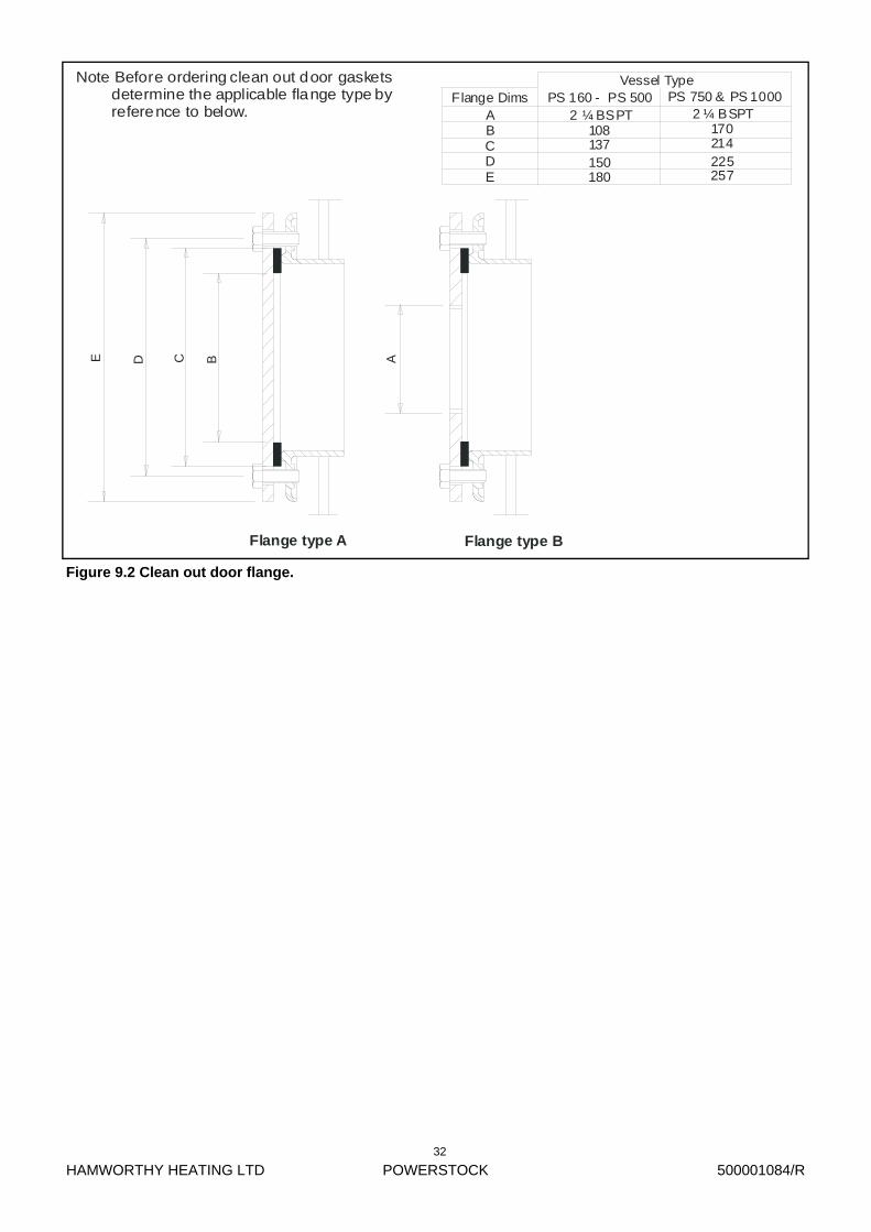
Figure 9.2 Clean out door flange.
Flange type A Flange type B
E D C B A
Note Before ordering clean out door gaskets determine the applicable flange type by reference to below.
Flange DimsVessel Type
PS 160 - PS 500 PS 750 & PS 1000ABCDE
2 ¼ BSPT108137150180
170214225257
2 ¼ BSPT
HAMWORTHY HEATING LTD
POWERSTOCK
500001084/R
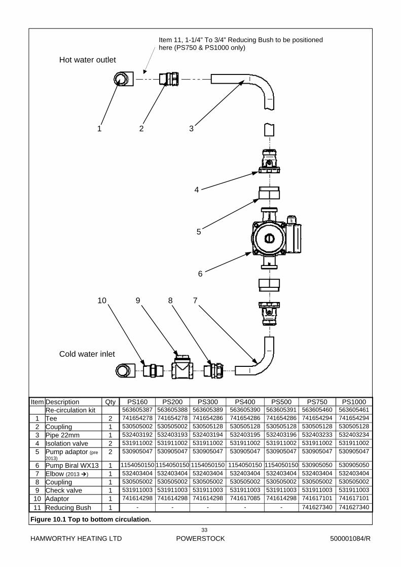
Item Description Qty PS160 PS200 PS300 PS400 PS500 Re-circulation kit 563605387 563605388 563605389 563605390 563605391
1 Tee 2 741654278 741654278 741654286 741654286 741654286
2 Coupling 1 530505002 530505002 530505128 530505128 530505128
3 Pipe 22mm 1 532403192 532403193 532403194 532403195 532403196
4 Isolation valve 2 531911002 531911002 531911002 531911002 531911002
5 Pump adaptor (pre 2013)
2 530905047 530905047 530905047 530905047 530905047
6 Pump Biral WX13 1 1154050150 1154050150 1154050150 1154050150 1154050150
7 Elbow (2013 ) 1 532403404 532403404 532403404 532403404 532403404
8 Coupling 1 530505002 530505002 530505002 530505002 530505002
9 Check valve 1 531911003 531911003 531911003 531911003 531911003
10 Adaptor 1 741614298 741614298 741614298 741617085 741614298
PS750 PS1000 563605460 563605461 741654294 741654294 530505128 530505128 532403233 532403234 531911002 531911002 530905047 530905047
530905050 530905050 532403404 532403404 530505002 530505002 531911003 531911003 741617101 741617101
11 Reducing Bush 1 - - - - - 741627340 741627340
10 9 8 7
6
5
4
3 2 1
Hot water outlet
Cold water inlet
Figure 10.1 Top to bottom circulation.
Item 11, 1-1/4” To 3/4” Reducing Bush to be positioned here (PS750 & PS1000 only)
33


Hamworthy Heating Accredited Agents
Customer Service Centre Hamworthy Heating Limited, Fleets Corner, Poole, Dorset BH17 0HH Telephone: 0845 450 2866 Fax: 01202 662522 Email: [email protected] Website: www.hamworthy-heating.com Hamworthy reserves the right to make changes and improvements which may necessitate alteration to the specification without prior notice.
North West England (Sales & Service)
Gillies Modular Services
210-218 New Chester Road, Birkenhead, Merseyside L41 9BG
tel: 0151 666 1030 fax: 0151 647 8101
Southern Ireland (Sales & Service)
HEVAC Limited
Naas Road, Dublin 12, Ireland
tel: 00 353 141 91919 fax: 00 353 145 84806
Northern Ireland (Sales & Service)
HVAC Supplies Limited
Unit A6, Dargan Court, Dargan Crescent, Belfast BT3 9JP
tel: 02890 747737 fax: 02890 741233
Scotland (Sales & Service)
McDowall Modular Services
2 Penston Road, Glasgow, Scotland G33 4AG
tel: 0141 336 8795 fax: 0141 771 9635
North East England (Service)
Allison Heating Products
12 Sunnyside Lane, Cleadon Village, Sunderland SR6 7XB
tel: 0191 536 8833 fax: 0191 536 9933
Hamworthy Heating Customer Service Centre
Sales
tel: 0845 450 2865
Technical Enquiries
tel: 0845 450 2865
Servicing
tel: 01202 662555
Spares
tel: 0845 450 2866