practical cases of fault prevented using partial discharge
TRANSCRIPT

Practical cases of fault prevented using Partial Discharge
measures
Andrej Sepcic RAM, Altanova, Italy

• Localized electrical discharge that only partially bridges the insulation between conductors
• Symptom of insulation deterioration
• A micro spark
• PD normally develop in air gaps or on insulation surfaces, due to defects in the insulation system
WHAT IS PD ?

THREE BASIC TYPES OF PD
Internal PD can occur inside the insulating system defect, such as voids or contaminants, and can eventually trigger electrical treeing.
Surface PD can occur in surfaces of insulating materials if the electric field is high, and can provoke insulation tracking.
Corona PD originated in correspondence of sharp tips or protrusions or in the HV connections, normally is not harmful.
HV
HV
HV

MAIN DEFECTS IN CABLE SYSTEMS
Main defects type:
Internal PD in the cable and its accessories
Surface PD on cable terminations
Corroded shield
Broken Jacket

MAIN DEFECTS IN CABLE SYSTEMS
HA
RM
FU
LN
ESS
MAIN INSULATION
JOINT
AND TERMINATION
SURFACE PD
CORRODED SHIELD
BROKEN JACKET
Internal PD in the cable and its accessories
Surface PD on cable terminations

WHY WE DETECT PD ?
Effective assessment with enhanced Technology able to
- find very small PD source, even below noise level – avoiding false
negatives
- separate noise and corona and identify true PD – avoiding false
positive
For a 230kV termination or joint, cost of false positive can exceed 200.000$,
considering:
- 3-5 stand-by days to repair/replace
- New joint or termination plus installation
- Extra testing day

HOW WE DETECT PD ON CABLES ?
passive inductive sensors for PD
installed around the ground connection of the accessories;
on/off line tests and permanent monitoring
Preferred sensor due to its high sensitivity
Close HFCT
Clamp HFCT
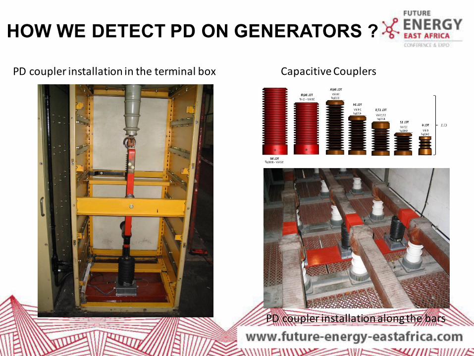
PD coupler installation along the bars
HOW WE DETECT PD ON GENERATORS ?
Capacitive Couplers PD coupler installation in the terminal box

Example of permanent sensor installation
for on-line test
HOW WE DETECT PD ON GENERATORS ?

WHAT DOES A TYPICAL RESULT LOOK LIKE
Black Phenomenon:
Background Noise
By applying real time filters, it is possible to see
the PD activities below the noise level
Pattern Recognition
Blue Phenomenon:
Surface PD
Red Phenomenon:
Internal PD

PRESENTATION GUIDELINES
Black Phenomenon
Disturbances/Noise
MULTIPLE PD
PHENOMENA
FOUND BELOW
NOISE LEVEL!
Red Phenomena:
Slot discharges
Sensitivity increase (test on 15kV Generator)
Blue Phenomena:
Embedded delamination Green Phenomena:
Stress grading

CASE STUDY 1
LOCATION EUROPE
EUT GAS TURBINE 120 MW
GENERATOR
RATED VOLTAGE
15 kV
INSULATION
VINTAGE
TYPE OF TEST
ON-LINE
PD SENSOR VARIOUS
. Boroscopic inspection confirms diagnosis.
CASE STUDY

CASE STUDY 1 – PD MEAS. SETUP
PD
Coupler

CASE STUDY 1 – PD MEAS. SETUP
PD
Couplers
Bus Bar

RESULTS U - PHASE
Classification map
Entire Pattern acquisition
Exciter noise
External discharge to
Phase U. Cross talk of distributed micro voids from Phase W
Distributed
microvoids in phase U
Discharges due to bar
to bar or bar to ground activity in overhang

Sub patterns III Level identification
RESULTS U - PHASE

Classification map Entire Pattern acquisition
Visual Inspection
RESULTS U - PHASE

RESULTS U - PHASE
PD traces found in 12 of the 60 slots
(7 white traces and 8 suspecious traces)
SLOT DISCHARGES
Results of endoscopic inspection on generator

On-line PD
measurements
Gather data to assess
the whole machine
conditions
In particular
Machine affected by:
ם Distributed micro-voids (all three phases)
ם Bar to bar (ground) discharges (phase U)
ם Slot Discharges
Unavoidable process in modern thermosetting insulation systems
The high frequency currents may degrade, in the course of time, both the stress grading system and the slot coating protection in the region where the bars leave the iron core.
Final considerations
Dangerous phenomenon: inspection and maintenance required
RESULTS U - PHASE
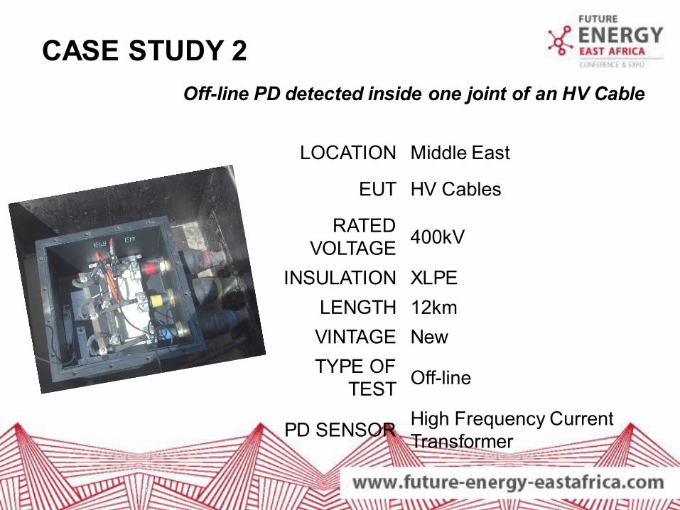
CASE STUDY 2
LOCATION Middle East
EUT HV Cables
RATED VOLTAGE
400kV
INSULATION XLPE
LENGTH 12km
VINTAGE New
TYPE OF TEST
Off-line
PD SENSOR High Frequency Current Transformer
Off-line PD detected inside one joint of an HV Cable
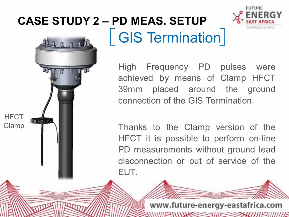
CASE STUDY 2 – PD MEAS. SETUP
GIS Termination
High Frequency PD pulses were
achieved by means of Clamp HFCT
39mm placed around the ground
connection of the GIS Termination.
Thanks to the Clamp version of the
HFCT it is possible to perform on-line
PD measurements without ground lead
disconnection or out of service of the
EUT.
HFCT Clamp

CASE STUDY 2 – PD MEAS. SETUP
HFCT Clamp
LFCT Accessible Joint
High Frequency PD pulses were achieved by means of Clamp
HFCT 39mm placed around the ground connection of the Joint.
Thanks to the Clamp version of the HFCT it is possible to perform
on-line PD measurements without ground lead disconnection or out
of service of the EUT.

RESULTS RED - PHASE
Equivalent Frequency analysis for the Internal PD activity detected
on the TF Classification Map (Red Cluster) allows to conclude:
PD activity inside one Joint of the phase under test
IDENTIFICATION
RED PHASE
R

RESULTS - LOCALISATION
Instruments made it possible to localize the Joint where PD derived from through Amplitude-Frequency analysis (First Level of PD Location).
4,5 MHz
7 MHz
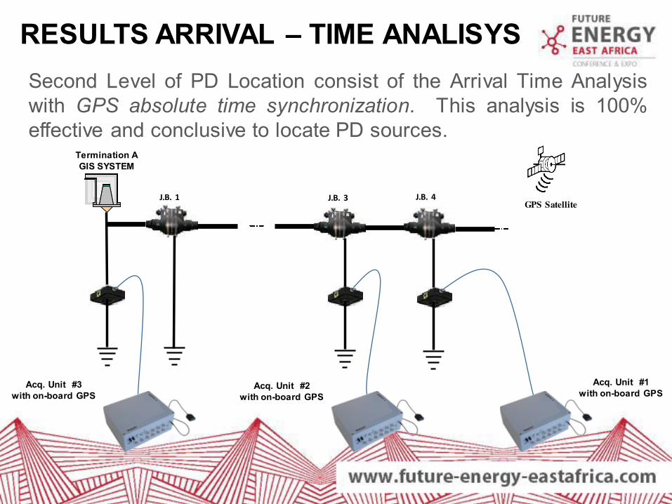
RESULTS ARRIVAL – TIME ANALISYS
Second Level of PD Location consist of the Arrival Time Analysis with GPS absolute time synchronization. This analysis is 100% effective and conclusive to locate PD sources.
Termination A
GIS SYSTEM
J.B. 4
Acq. Unit #1
with on-board GPS
GPS Satellite J.B. 3 J.B. 1
Acq. Unit #2
with on-board GPS
Acq. Unit #3
with on-board GPS

RESULTS ARRIVAL – TIME ANALISYS
J.B. 4
J.B. 3
Termination A
This method allows to localize the PD source thanks to the arrival time differences of the pulses between the three different locations.
The PD was localized in J.B.
4
During the inspection, Techimp diagnosis was confirmed: Burning traces were founded in the
Joint Bay 4

SUGGESTED ACTIONS
Considering amplitude and repetition rate of detected PD it was suggested to:
1 - Replace the Joint affected from Internal PD activity in order to avoid unexpected failures
and consequent explosion during service.
2 – Regular basis PD Measurements in order to do a periodically check of the cable.
SOLUTION PD measurement on/off-line

SUGGESTED ACTIONS
Thank you for your attention !