prague metro instrumentation - civil engineering · prague metro instrumentation geotechnics ......
TRANSCRIPT

PraguePrague Metro Metro InstrumentationInstrumentation
GeotechnicsGeotechnics –– Jan Jan ZaleskyZaleskyGeophysicGeophysics s –– JaromirJaromir MachacekMachacek
MicroMicro--monitoring systemmonitoring system –– MatinMatin VanicekVanicek
CzechCzech TechnicalTechnical University in University in PraguePrague
UNDERGROUND MUNDERGROUND M33 MEETING AT BARCELONAMEETING AT BARCELONA17th and 18th April 200617th and 18th April 2006
Florenc Metro station 25/10/06 at 00:36

Prague Metro – Site plan
Faculty of CE Florenc
Vltavska
Holesovice

Instrumentations in section: km 18,725 Line C, Track No. 2
Micro-communication test area, Line A
Tunnel lining host rock:
Ordovician period, degree beroun
Dark grey wacke, wacke-shale with sandstone and/or quartzite, facies of claystone
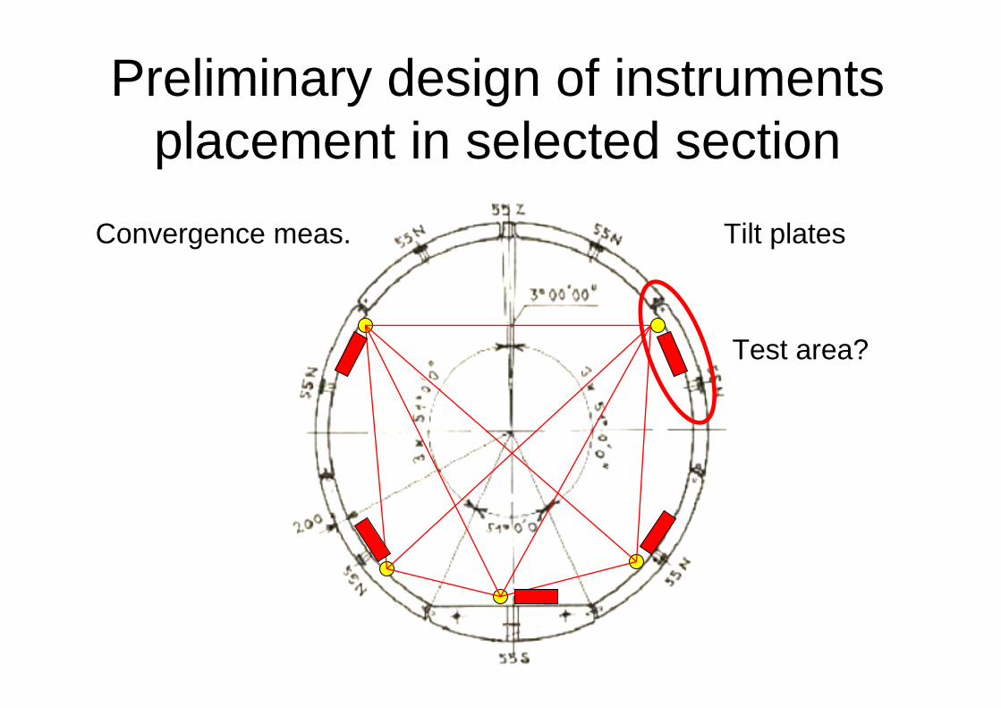
Convergence meas. Tilt plates
Preliminary design of instruments placement in selected section
Test area?

View – direction Vltavska station

Placement of instrumentation
Section in km 18,725

Selected tubing for
the test area
Line C, Track No. 2 Section in km18,725

Placement of tilt plates and convergence bolts
• Symmetric• TP + CB to be
close as much as possible
• In relation to to the test area25,4°
C 04,4°L 00,6°
09,8°
47,6°51,7°
Angles of inclination of tilt plates after installation
Test area

Tilt plate 2.01and convergence bolt

Convergence bolt and tilt plate
2.02

Convergence bolt 2.04
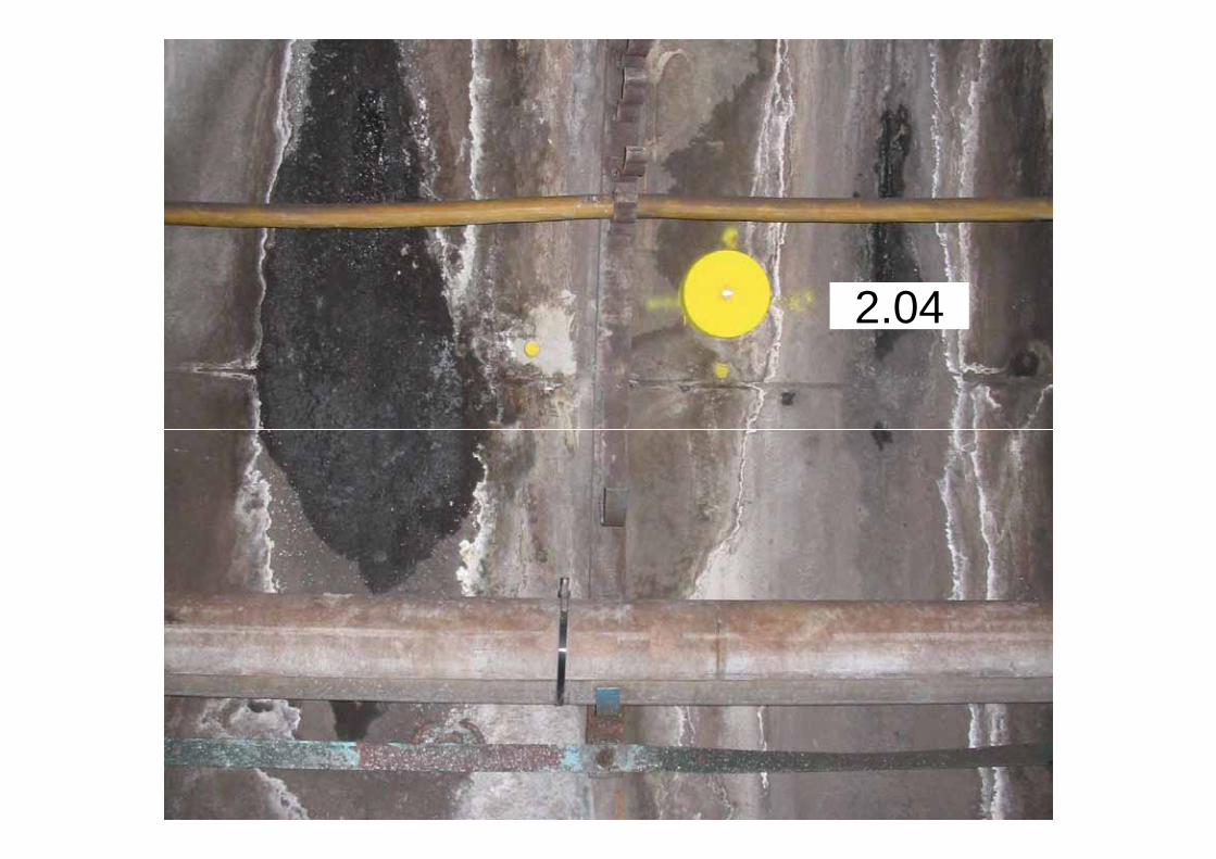
2.04

Tilt plate 2.05
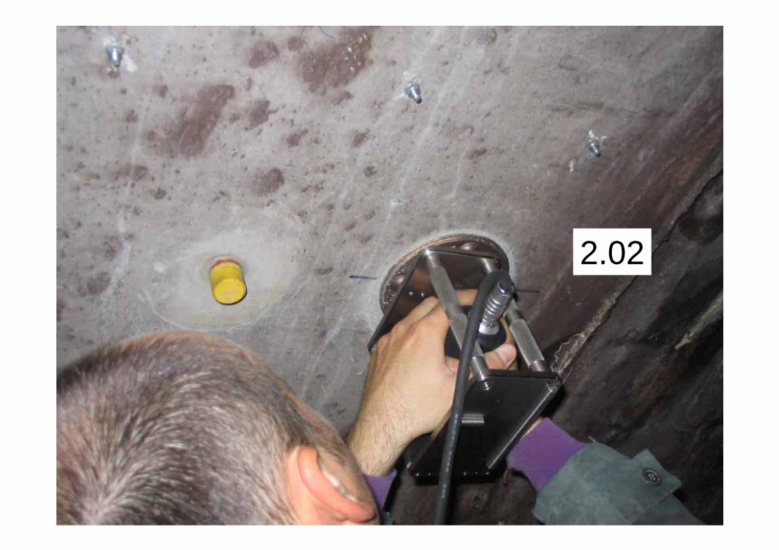
2.02

2.05

Results of tilt measurement in mm/m
22/12/06
22/12/06
22/12/06
10/01/06
10/01/07
10/01/07 0,12
12/04/07 -0,18
12/04/07 -0,28
10/01/07 -0,28
12/04/07 -0,52
12/04/07 0,32
10/01/07 0,24
12/04/07 0,68
10/01/07 -0,72
12/04/07 -0,74
C: L:
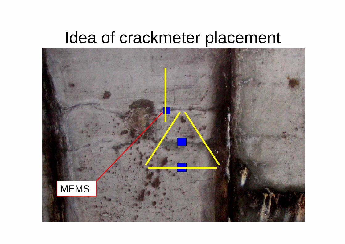
Idea of crackmeter placement
MEMS

Geokon crackmeter: range 12,5 mm
320 ± 10 mm
Spacing mark
30 mm

Location of crackmeter pattern

And what about the helmet?

2.02

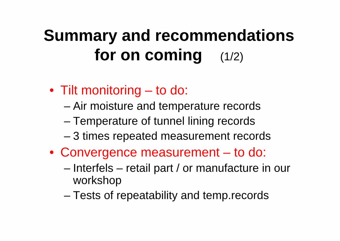
Summary and recommendations for on coming (1/2)
• Tilt monitoring – to do:– Air moisture and temperature records– Temperature of tunnel lining records– 3 times repeated measurement records
• Convergence measurement – to do:– Interfels – retail part / or manufacture in our
workshop– Tests of repeatability and temp.records

Summary and recommendations for on coming (2/2)
• Crackmeter:– Steel pattern application for core boring – Manual readings of four crackmeters– Connection to system / at the min. 2 data-
loggers application• Input for digital imaging:
– Repeated digital snaps sequences in thesection km 18,725
• Resolution shall be increased (now 3,2 MP)

Anticipation / optimistic / contemplating / …
Meeting at Prague 24/10/2006

Acknowledgements
to colleagues from UPC Barcelona for arrangement of the meeting,
to you all for your notes, comments and discussion,
to the Czech Science Fund for financial support of the project GA 103/06/1257

RESEARCH ONUNDERGROUND STRUCTURES AGEING
WITH EXPLOITATION OF MONITORINGAND MICROMEASUREMENT SYSTEMS -
AUXILIARY METHODS II
Proposer: Prof. Ing. Ivan Vaníček, DrSc.Author of the report: RNDr. Jaromír Macháček, Ph.D.
Czech Technical University in Prague
Grant Agency of Czech Republic, Reg. Nr. 103/06/1257:

Research of underground structures ageing with exploitation of monitoring and micro-measurement systems
AUXILIARY METHODS II - GA CR Reg. Nr. 103/06/1257:
Round about the turn of the past year we have prepared application of 2 other auxiliary methods, which have to observe two selected parts of tunnel lining and complement the base monitoring system. Instalation was completed at monitoring profile on line C, rail Nr.2, kilometer spacing 18,725 of Prague METRO, and aimed to:
a) monitoring of dynamic behaviour changes time-development of selected parts under the traffic loads,
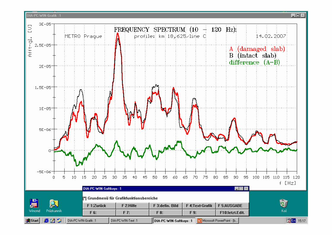
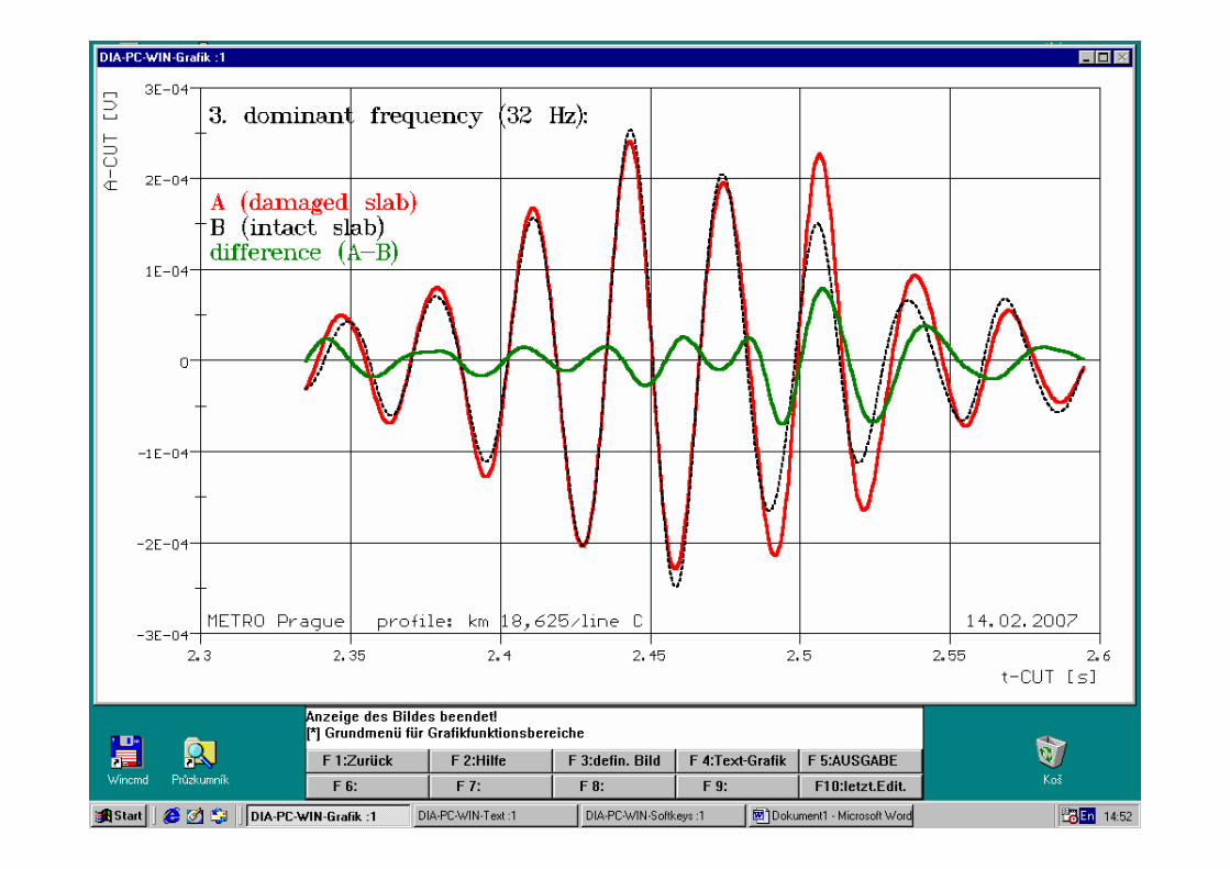
b) monitoring of fatigue failure time-development by means of examination of elastic waves spreading parameters.
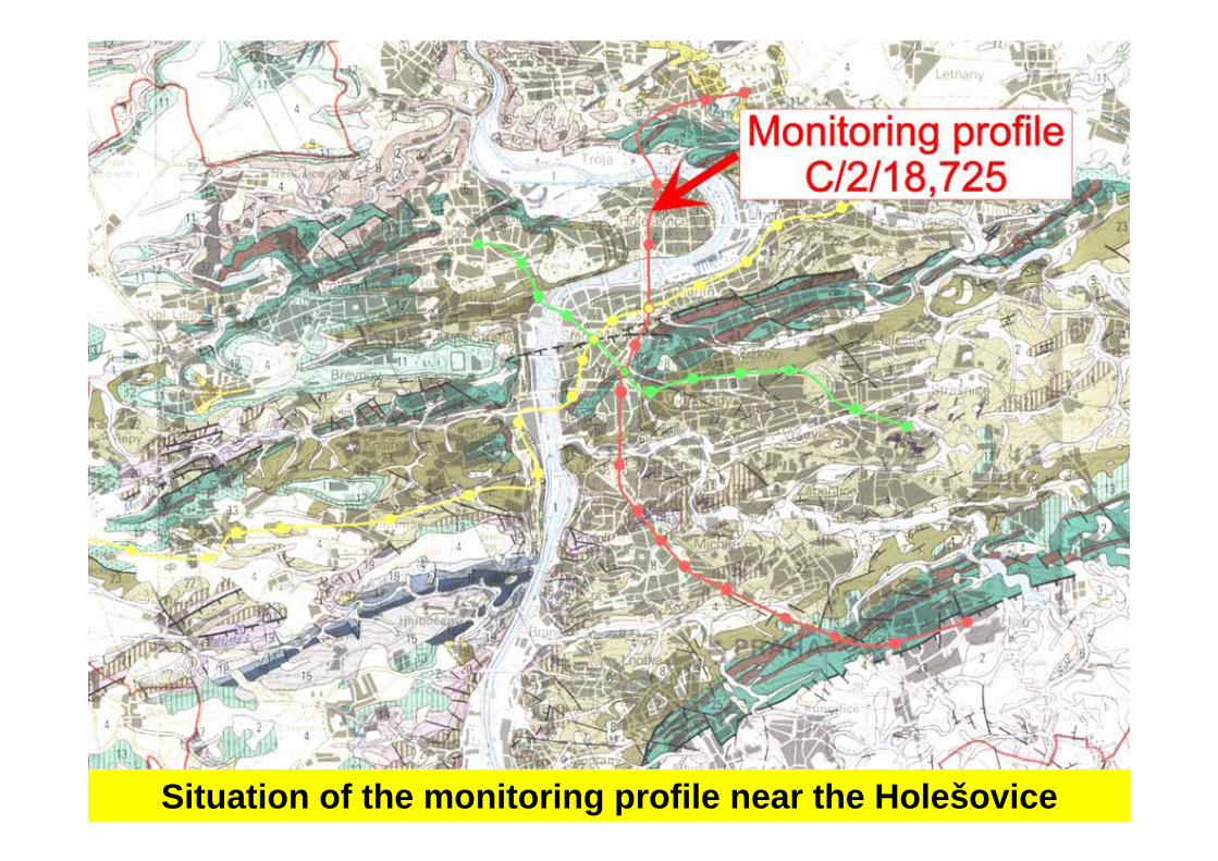
Situation of the monitoring profile near the Holešovice

Scheme of complex monitoring profile instrumentation under the Holešovice Station -auxiliary methods (METRO Prague, line C, rail Nr. 2, kilometer spacing 18,725) .

Geophones coated by copper cases with cabling prior to the instalation into a tunnel lining.
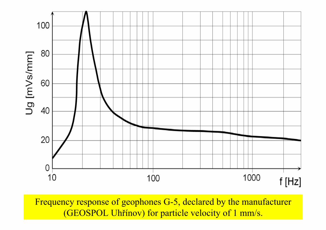
Frequency response of geophones G-5, declared by the manufacturer (GEOSPOL Uhřínov) for particle velocity of 1 mm/s.
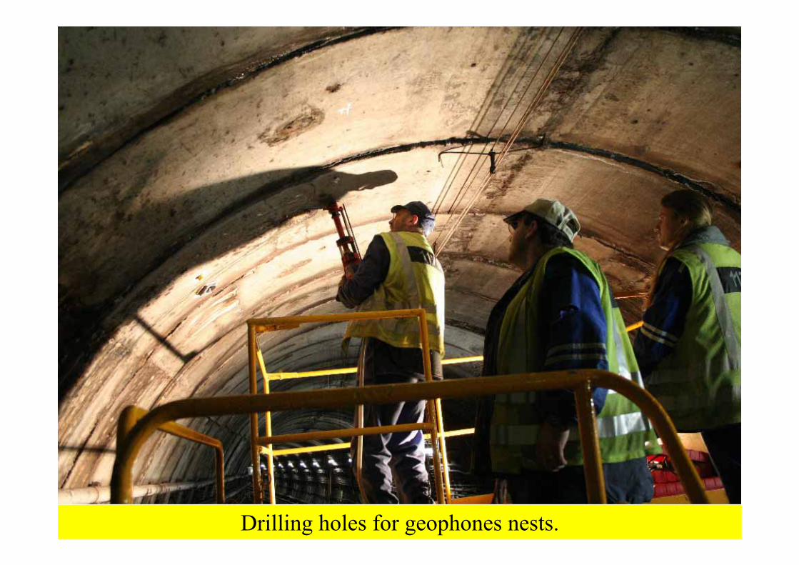
Drilling holes for geophones nests.

Sticking of monitoring geophone into its nest by a silicon sealant.

Detailed view of acoustic sampling field and monitoring geophone G1 installed.

Monitoring geophone after the instalation (G1 in the defected slab).

The key moment of the cabling instalation - passing through the hydraulic safety barrier of the Holešovice Station.
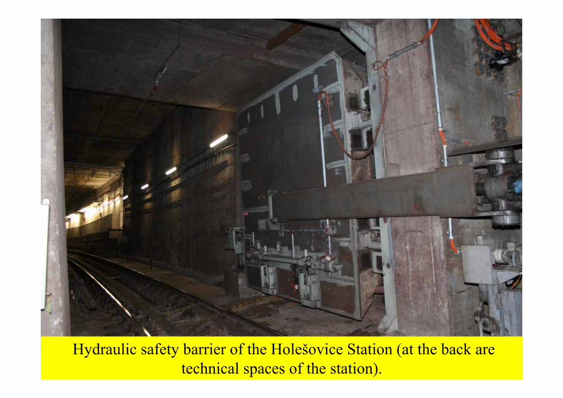
Hydraulic safety barrier of the Holešovice Station (at the back are technical spaces of the station).

Passing through the pressure safety barrier of Holešovice Station (the outer side of the closure).

Passing through the pressure safety barrier of Holešovice Station with the detailed view to cable grommets (the outer side of the closure).

Fixation of acoustic sampling points by dowel pins.

Acoustic sampling field with hole prepared for monitoring geophone instalation.

Set of fixed points for acoustic sampling application and the geophone G1 at monitored profile near the Holešovice Station.

Scheme of complex monitoring profile instrumentation under the Holešovice Station -auxiliary methods (METRO Prague, line C, rail Nr. 2, kilometer spacing 18,725) .

WSN in Prague metroWSN in Prague metro
Martin VanMartin Vanííčček ek -- CTUCTU

ContentsContents
Site locationSite locationCoordination with Prague metroCoordination with Prague metro–– Paperwork / permitsPaperwork / permits–– Site & work logisticsSite & work logisticsInstallation of the WSNInstallation of the WSN–– RequirementsRequirements–– Actual workActual workHandover to Oleg Handover to Oleg PodsechinPodsechin
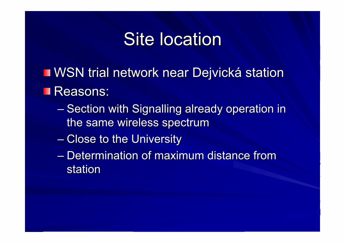
Site locationSite location
WSN trial network near DejvickWSN trial network near Dejvickáá stationstationReasons:Reasons:–– Section with Signalling already operation in Section with Signalling already operation in
the same wireless spectrumthe same wireless spectrum–– Close to the UniversityClose to the University–– Determination of maximum distance from Determination of maximum distance from
stationstation

Site location Site location -- mapmap

Coordination Coordination -- permitspermits
1.1. Specification what we want to doSpecification what we want to do2.2. Metro to specify restrictions / Metro to specify restrictions /
requirements / possible requirements / possible collissionscollissions with with existing systemsexisting systems
3.3. Meeting with all interested partiesMeeting with all interested parties4.4. SubmitionSubmition of our proposal with of our proposal with
implemented requirements from Metroimplemented requirements from Metro

Coordination Coordination –– site logisticssite logistics
In advance specification of our workIn advance specification of our workDetermination of required personal Determination of required personal resources from Metroresources from MetroDetermination of required machinery, Determination of required machinery, equipment for the work from Metroequipment for the work from MetroDetermination of our own resources Determination of our own resources (personal & material)(personal & material)Works schedule agreementWorks schedule agreement
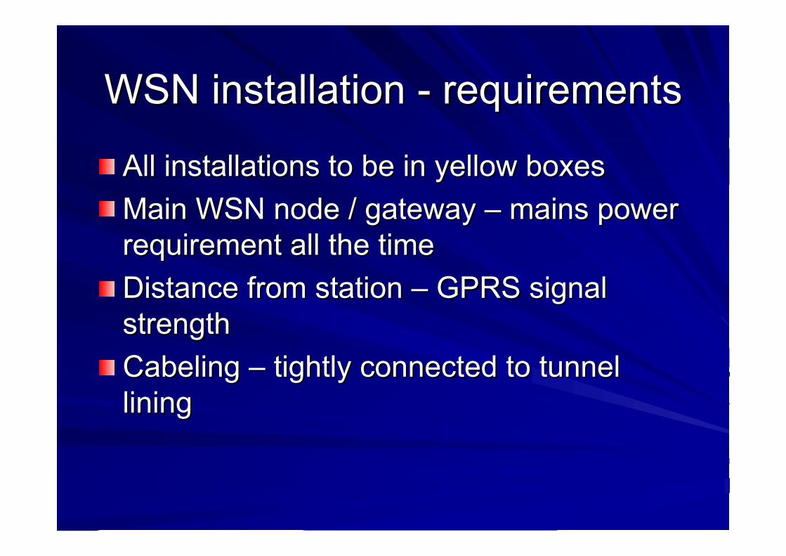
WSN installation WSN installation -- requirementsrequirements
All installations to be in yellow boxesAll installations to be in yellow boxesMain WSN node / gateway Main WSN node / gateway –– mains power mains power requirement all the timerequirement all the timeDistance from station Distance from station –– GPRS signal GPRS signal strengthstrengthCabelingCabeling –– tightly connected to tunnel tightly connected to tunnel lininglining

WSN installation WSN installation –– actual workactual work
Off site preparationOff site preparation–– Painting of boxesPainting of boxes–– WSN motes programmingWSN motes programming–– Gateway / Gateway / StargateStargate interconnection & box fittinginterconnection & box fitting

WSN installation WSN installation –– actual workactual workSite work:Site work:–– Drilling for plugs / fastening of boxes via screws with Drilling for plugs / fastening of boxes via screws with
washerswashers–– Placement of motes with sensors / gateway into boxesPlacement of motes with sensors / gateway into boxes–– Fixing of the cables to the tunnel facilities / installationsFixing of the cables to the tunnel facilities / installations

WSN installation WSN installation –– actual workactual work
Diagnostics if the WSN as installed worksDiagnostics if the WSN as installed works

Handover to Oleg Handover to Oleg PodsechinPodsechin
Thank you for your attentionThank you for your attention

Prague Installation
implementation and issues encountered

WiFi and ZigBee
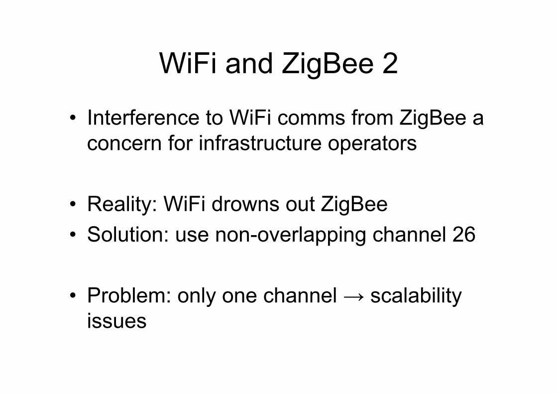
WiFi and ZigBee 2
• Interference to WiFi comms from ZigBee a concern for infrastructure operators
• Reality: WiFi drowns out ZigBee• Solution: use non-overlapping channel 26
• Problem: only one channel → scalability issues


0 14 31 50
5
4
3
2
1
76 8

System Breakdown
Data Flow:
Sensors→Local Connection
→ Remote ConnectionDatabase

Local Connectivity
• effective mote-to-mote range: 15 m• predictable network topology for small net
• both star and mesh topologies tested
• relay nodes the weakest point• integration of sensing and comms an issue

Local Improvements
• mote-to-mote range increase• ease of replacing batteries• ease of disabling motes to reconfigure net• adaptive sampling frequency


Remote Connectivity
• crucial as it allows for reconfiguration, real time updates
• problematic due to:– limited connectivity options (GPRS)– unreliable components (router, modem)– external provider policies (operator)– complexity of software/scripts/setup

Remote Connectivity 2• router behind firewall/NAT, but needs to act as
server
• client/server roles reversed → worst possible scenario
• router is a black box, if something goes wrong only way to debug is to go on-site
• should try to maintain connection at all costs by– constantly sending keep-alive data (ping) – resetting the hardware and connection
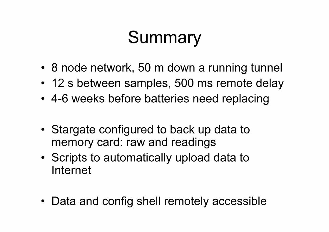
Summary• 8 node network, 50 m down a running tunnel• 12 s between samples, 500 ms remote delay• 4-6 weeks before batteries need replacing
• Stargate configured to back up data to memory card: raw and readings
• Scripts to automatically upload data to Internet
• Data and config shell remotely accessible