pranavi ppt presention of 3d power
DESCRIPTION
Power Point Presentation on 3d powerTRANSCRIPT

What is What is Transformer ??Transformer ??
A transformer is a A transformer is a static device static device which is use to which is use to convert high convert high alternatic voltage alternatic voltage to a low alternatic to a low alternatic voltage and vice voltage and vice versa, keeping the versa, keeping the frequency same.frequency same.

Principle Of Principle Of OperationOperation
Transformer works on Transformer works on the principle of the principle of mutual induction of mutual induction of two coils. When two coils. When current in the primary current in the primary coil is changed the coil is changed the flux linked to the flux linked to the secondary coil also secondary coil also changes. changes. Consequently an EMF Consequently an EMF is induced in the is induced in the secondary coil. secondary coil.

What is Induction What is Induction law ??law ??
Faraday’s law states that:Faraday’s law states that:
Vs=Ns.dVs=Ns.dΦΦ/dt /dt where where VSVS is the instantaneous is the instantaneous
secondry winding voltage. secondry winding voltage. NSNS is the number of turns in is the number of turns in
the secondary coil.the secondary coil.
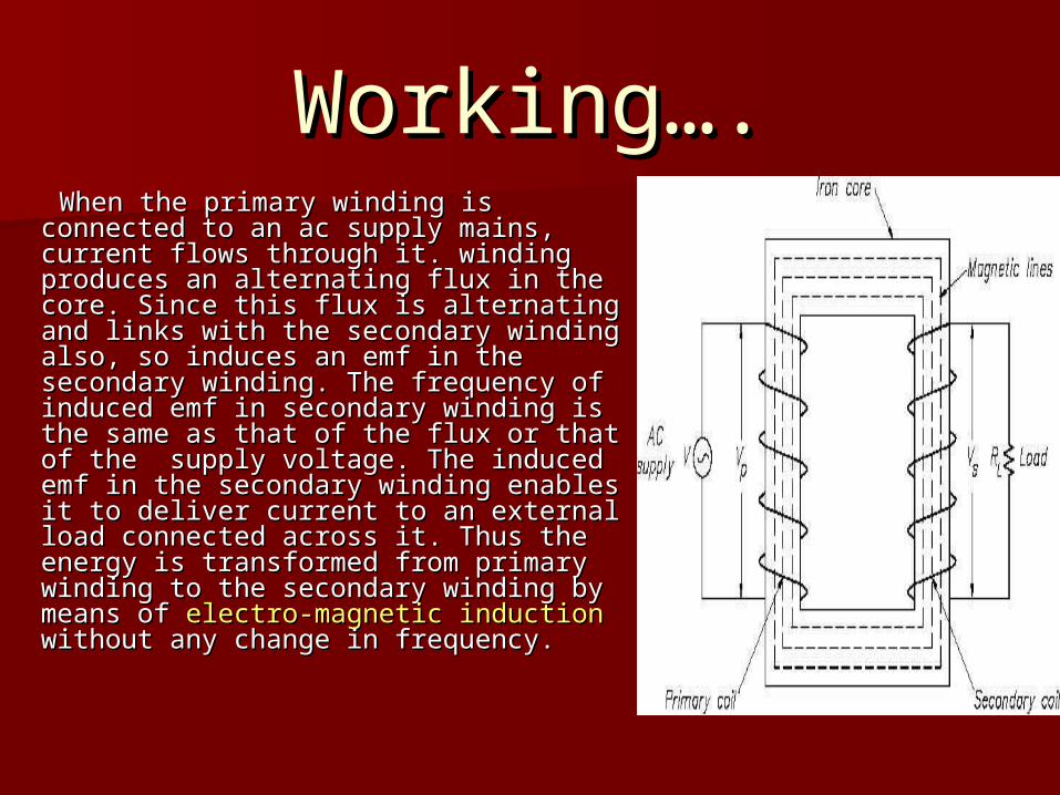
Working….Working…. When the primary winding is When the primary winding is
connected to an ac supply mains, connected to an ac supply mains, current flows through it. winding current flows through it. winding produces an alternating flux in the produces an alternating flux in the core. Since this flux is alternating and core. Since this flux is alternating and links with the secondary winding also, links with the secondary winding also, so induces an emf in the secondary so induces an emf in the secondary winding. The frequency of induced winding. The frequency of induced emf in secondary winding is the same emf in secondary winding is the same as that of the flux or that of the as that of the flux or that of the supply voltage. The induced emf in supply voltage. The induced emf in the secondary winding enables it to the secondary winding enables it to deliver current to an external load deliver current to an external load connected across it. Thus the energy connected across it. Thus the energy is transformed from primary winding is transformed from primary winding to the secondary winding by means of to the secondary winding by means of electro-magnetic inductionelectro-magnetic induction without without any change in frequency. any change in frequency.

Construction of Construction of TransformerTransformer
Mainly Transformers Mainly Transformers have two types of have two types of construction….construction….
CORE type CORE type constructionconstruction
SHELL type SHELL type constructionconstruction
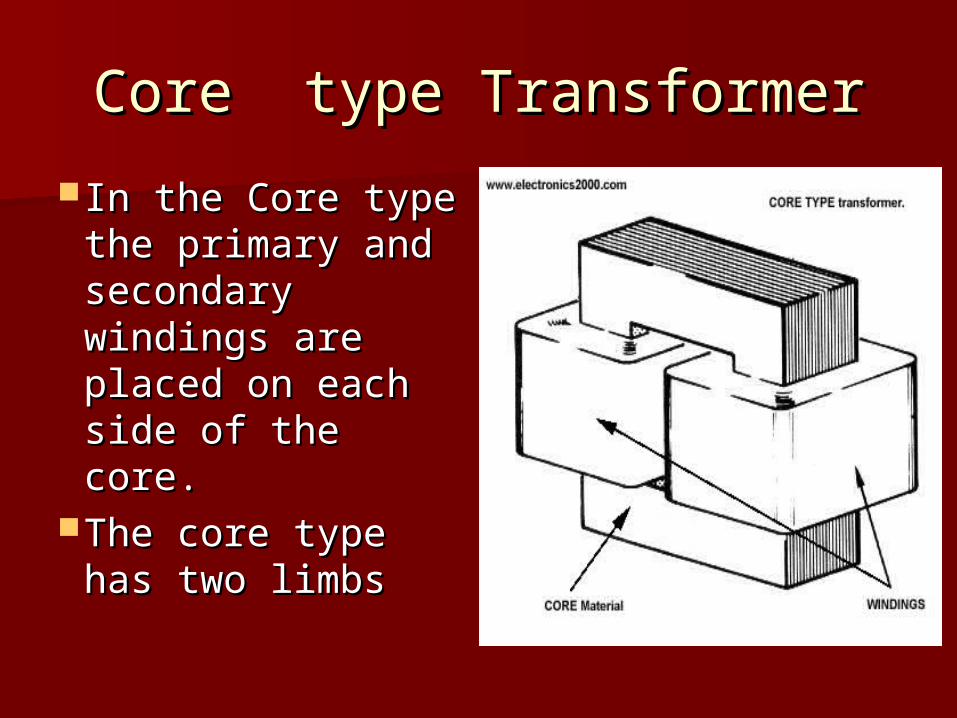
Core type TransformerCore type Transformer
In the Core type In the Core type the primary and the primary and secondary secondary windings are windings are placed on each placed on each side of the core. side of the core.
The core type The core type has two limbs has two limbs

Shell type Shell type TransformerTransformer
In Shell type In Shell type transformers the transformers the LV & HV LV & HV windings are windings are sandwiched sandwiched between each between each other.other.shell type has shell type has three limbs. three limbs.
Types of Types of TransformerTransformer Step UP TransformerStep UP Transformer : :
A transformer in which Ns>Np is called a A transformer in which Ns>Np is called a step up transformer. A step up transformer step up transformer. A step up transformer is a transformer which converts low is a transformer which converts low alternatic voltage to high alternatic alternatic voltage to high alternatic voltage. voltage.
Step DOWN TransformerStep DOWN Transformer : : A transformer in which Np>Ns is called a A transformer in which Np>Ns is called a
step down transformer. A step down step down transformer. A step down transformer is a transformer which transformer is a transformer which converts high alternatic voltage to low converts high alternatic voltage to low alternatic voltage. alternatic voltage.

A wide variety of transformer designs A wide variety of transformer designs are used for different applications.are used for different applications.
Auto-transformerAuto-transformer Poly-phase transormerPoly-phase transormer Leakage transformerLeakage transformer Resonant transformerResonant transformer Instrument transformers Instrument transformers

AUTO-TRANSFORMERSAUTO-TRANSFORMERS
Autotransformer Autotransformer is a one winding is a one winding transformer in transformer in which a part of which a part of the winding is the winding is common to both common to both HV & LV sides.HV & LV sides.

POLY-PHASE TRANSFORMERPOLY-PHASE TRANSFORMER
Three separate single Three separate single phase transformers phase transformers are suitably connected are suitably connected for 3 phase operation.for 3 phase operation.
A single three phase A single three phase transformer in which transformer in which the cores and the cores and windings for all the windings for all the three phases are three phases are combined in a single combined in a single structure. structure.

INSTRUMENT INSTRUMENT TRANSFORMERSTRANSFORMERS
A current A current transformer is a transformer is a measurement measurement device designed device designed to provide a to provide a current in its current in its secondary coil secondary coil proportional to proportional to the current the current flowing in its flowing in its primary.primary.
A voltage A voltage transformer are transformer are designed to have designed to have an accurately an accurately known known transformation transformation ratio in both ratio in both magnitude and magnitude and phase, over a phase, over a range of range of measuring circuit measuring circuit impedances.. impedances..
A A current current transformertransformer is a is a measurement measurement device designed device designed to provide a to provide a current in its current in its secondary coil secondary coil proportional to proportional to the current the current flowing in its flowing in its primary.primary.
A A voltage voltage transformertransformer are designed are designed to have an to have an accurately accurately known known transformation transformation ratio in both ratio in both magnitude and magnitude and phase, over a phase, over a range of range of measuring measuring circuit circuit impedances.. impedances..
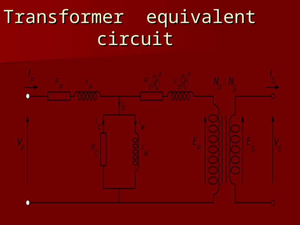
Transformer equivalent Transformer equivalent circuitcircuit

Losses In Losses In Transformers….Transformers….
Iron Losses – Iron Losses – These are These are the hysteresis loss and eddy the hysteresis loss and eddy current loss, constant loss. current loss, constant loss.
Each time the magnetic field Each time the magnetic field is reversed, a small amount is reversed, a small amount of energy is lost due to of energy is lost due to hysteresis within the core. within the core.
The The eddy current losseddy current loss is a is a complex function of the complex function of the square of supply frequency square of supply frequency and inverse square of the and inverse square of the material thicknessmaterial thickness
Copper Copper Loss :Current Loss :Current flowing through the flowing through the windings causes windings causes resistive heating of of the conductors. At the conductors. At higher frequencies, higher frequencies, skin effect and and proximity effect create additional create additional winding resistance winding resistance and losses. and losses.

TestingTesting
Open circuit Open circuit testtest
Short circuit Short circuit testtest


Applications…Applications…
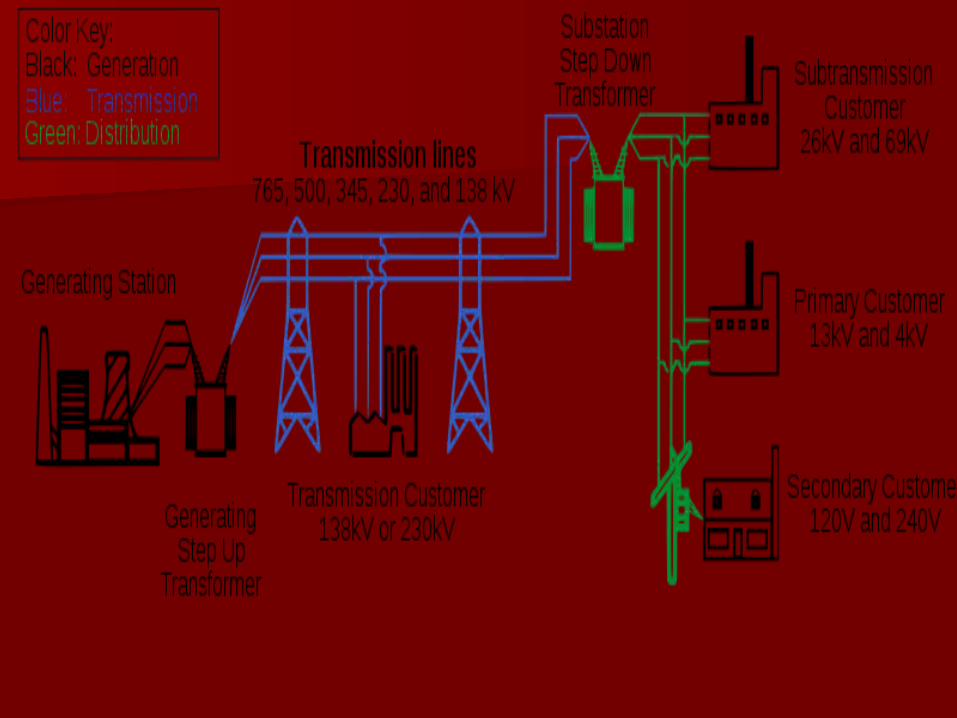
POWER TRANSMISSIONPOWER TRANSMISSION : :
A major application of transformers is to increase A major application of transformers is to increase voltage before voltage before transmitting electrical energy over over long distances through wires. Wires long distances through wires. Wires have resistance and so dissipate electrical energy have resistance and so dissipate electrical energy at a rate proportional to the square of the current at a rate proportional to the square of the current through the wire. By transforming electrical through the wire. By transforming electrical power to a high-voltage (and therefore low-power to a high-voltage (and therefore low-current) form for transmission and back again current) form for transmission and back again afterward, transformers enable afterward, transformers enable economical transmission of power over long economical transmission of power over long distances .distances .

IN ELECTRONICS :IN ELECTRONICS :
Transformers are also used Transformers are also used extensively in electronic products to extensively in electronic products to step down the supply voltage to a step down the supply voltage to a level suitable for the low voltage level suitable for the low voltage circuits they contain. The circuits they contain. The transformer also electrically isolates transformer also electrically isolates the end user from contact with the the end user from contact with the supply voltage .supply voltage .

THERMIC POWER THERMIC POWER STATIONSSTATIONS
The transformer steps The transformer steps up the generator up the generator voltage (400V or 690V voltage (400V or 690V for low power stations, for low power stations, 6.3kV or 11kV for 6.3kV or 11kV for higher power stations) higher power stations) in order to adapt it to in order to adapt it to the network voltage the network voltage (generally 20kV)(generally 20kV)

CautionCaution Transformer must not be connected to a direct Transformer must not be connected to a direct
source. If the primary winding of a transformer is source. If the primary winding of a transformer is connected to a dc supply mains, the flux connected to a dc supply mains, the flux produced will not vary but remain constant in produced will not vary but remain constant in magnitude and therefore no emf will be induced magnitude and therefore no emf will be induced in the secondary winding except at the moment in the secondary winding except at the moment of switching on. Thus the transformer can not be of switching on. Thus the transformer can not be employed for raising or lowering the dc voltage. employed for raising or lowering the dc voltage. Also there will be no back induced emf in the Also there will be no back induced emf in the primary winding and therefore a heavy current primary winding and therefore a heavy current will be drawn from the supply mains which may will be drawn from the supply mains which may result in the burning out of the winding. result in the burning out of the winding.