prc 2000 systems - igor chudovigor.chudov.com/manuals/prc2000/prc2000.pdf · manual improvement...
TRANSCRIPT

1
SYSTEM OPERATION
& MAINTENANCE
MANUAL
PRC 2000 SYSTEMS

2

3
MANUAL NO. 5050-0313
REV. G

4
TITLE PAGE
General Information .......................................................................................................................... 7Use Of This Manual ................................................................................................................... 7Introduction ................................................................................................................................ 7Specifications ............................................................................................................................ 8Capabilities ................................................................................................................................ 10
Primary Controls ................................................................................................................. 11Pulse Heat .......................................................................................................................... 12Pulse Plate ......................................................................................................................... 13MicroChine .......................................................................................................................... 14Pik And Paste ..................................................................................................................... 15Thermal Management Center ............................................................................................... 16
Parts Identification ..................................................................................................................... 18System ............................................................................................................................... 18Front Panel Features ........................................................................................................... 19Rear Panel .......................................................................................................................... 27
Safety ........................................................................................................................................... 29Set-Up ........................................................................................................................................... 31
System ...................................................................................................................................... 31Handpiece Vacuum/Pressure ..................................................................................................... 33
Procedures .......................................................................................................................... 33Operation ......................................................................................................................................... 37
Introduction ................................................................................................................................ 37Definitions .................................................................................................................................. 37Thermal Management Center ..................................................................................................... 38
Power Up ............................................................................................................................ 39Operation ............................................................................................................................ 39Factory Settings ..................................................................................................................Tip & Temperature Selection ................................................................................................ 50Password ............................................................................................................................ 51Calibration ........................................................................................................................... 62Temperature Limits .............................................................................................................. 66Temperature Setback .......................................................................................................... 68Automatic Power Down ....................................................................................................... 72Digital Readout Message Codes ......................................................................................... 73Quick Reference - System Operation .................................................................................. 75
Foot Pedal ................................................................................................................................. 78
TABLE OF CONTENTS

5
TITLE PAGE
Pik And Paste ..................................................................................................................... 79Paste Dispenser ............................................................................................................ 79
Vacuum Pick ....................................................................................................................... 86MicroChine .......................................................................................................................... 89
Set-Up........................................................................................................................... 89Probe Brake Operation .................................................................................................. 90
Pulse Plate .......................................................................................................................... 93Set-Up........................................................................................................................... 93
Pulse Heat ........................................................................................................................... 97Set-Up........................................................................................................................... 97Operation ...................................................................................................................... 99Reference Guidelines .................................................................................................... 100
Corrective Maintenance .............................................................................................................. 103VisiFilter Element Replacement ........................................................................................... 103Handpieces ......................................................................................................................... 104Power Source ...................................................................................................................... 106
Replacement Parts .................................................................................................................... 112Power Source ...................................................................................................................... 112System Packaging .............................................................................................................. 113System Handpieces ............................................................................................................ 114System Accessories ........................................................................................................... 115SensaTemp Handpieces ...................................................................................................... 116Manual Improvement & Comment Form ............................................................................... 115
Warranty .................................................................................................................................... 117
TABLE OF CONTENTS

6
PACE, INCORPORATED RETAINS THE RIGHT TO MAKE CHANGES TO SPECIFICATIONSCONTAINED HEREIN AT ANY TIME, WITHOUT NOTICE.
THE FOLLOWING ARE REGISTERED TRADEMARKS AND/OR SERVICE MARKS OF PACE,INCORPORATED, LAUREL, MARYLAND, USA AND MAY ONLY BE USED TO IDENTIFYGENUINE PACE PRODUCTS OR SERVICES.
ARM-EVAC®, Flo-D-Sodr®, Mini-Wave®, PACE®, SensaTemp®, Snap-Vac®, SODRTEKSM, Sodr-X-Tractor® , THERMO-DRIVE®, ThermoFlo®, ThermoJet®, ThermoTweeze®, TOOLNET®, VisiFilter®,PERMAGROUNDTM, Tip-BriteTM, Auto-OffTM
Additional copies of this manual or other PACE literature may be obtained from:
www.paceworldwide.com
PACE USA PACE Europe9893 Brewers Court Sherbourne HouseLaurel, MD 20723 Sherbourne DriveUSA Tilbrook, Milton Keynes
MK7 8HXUnited Kingdom
Tel: (301) 490-9860 (44) 01908-277666(888)-535-PACE
Fax: (301) 498-3252 (44) 01908-277777

7
USE OF THIS MANUAL
The information contained in this manual will provide the user with the basic knowledge necessary toproperly operate and maintain the PACE model PRC 2000 system. The additional manuals included withyour system will provide the user with specific operational features of the associated accessory. PACESTRONGLY RECOMMENDS THAT THE USER READ AND FULLY UNDERSTAND THE “OPERATION”PORTIONS OF THIS MANUAL PRIOR TO USE OF SYSTEM IN COMPONENT REMOVAL/REPLACEMENT OPERATIONS. The “Quick Reference-System Operation” Guide is provided as aconvenient reference for day-to-day operation of the Thermal Management Center portion of this system. Ifyou encounter any difficulty operating your system, call your local authorized PACE distributor or contactPACE Applications Engineering directly at Tel. (301) 490-9860 or FAX (301) 604-8782.
INTRODUCTION
The PRC 2000 is a Process Control System for Universal Assembly and Repair of ElectronicAssemblies. The systems include the power source with a selection of accessories and functional aids.The systems are available in a variety of package configurations to suit your needs.
The PRC 2000 systems are available in either the 100 VAC version, the 115 VAC version or the 230 VACversion. The Power Source houses five functional sections. The following is a brief description of eachsection.
The PRC 2000 THERMAL MANAGEMENT CENTER incorporates outputs for specialized SensaTemphandpieces for safe installation and removal of virtually all surface mount and thru-hole components.Three auxiliary channels provide SensaTemp control of separately sold AC line-powered accessories.Continuous automatic calibration, auto power down and a built-in software password function assureconsistent operator performance, reliability and security.
The PIK AND PASTE section features a self-contained high pressure air supply with timing control forprecise dispensing of solder paste and other materials. The vacuum pick has a finger actuated releasefor convenient component handling.
The PRC 2000 MICROCHINE is a lightweight, variable speed machining handpiece for precise circuitryand substrate repair. With its tachometer feedback, the MicroChine can maintain controlled drilling andmilling rates under varying loads. The MicroChine’s patent pending PROBE BRAKE feature instantlystops machining at a selected layer depth for safe multilayer repair.
The PULSE HEAT section provides variable controlled, low voltage AC pulse power to an array ofspecialized handpieces for safe surface mount rework, circuitry repair, auxiliary heating, coating removaland thermal wire stripping.

8
INTRODUCTION CONT'D
The PULSE PLATE section provides variable controlled DC pulse power for high-quality cleaning andelectroplating of edge connectors and other circuit contacts with nickel, gold and other metals.The SR-4 “Safety Rating” designation on the back panel is your assurance that the PRC 2000 meets orexceeds all applicable civilian and military standards (including MIL-STD-2000A, and WS-6536),EOS\ESD and worldwide electrical codes. The 230 VAC version system bears the CE ConformityMarking which assures the user that it conforms to all the requirements of council directive EMC 89/336/EEC. The 115 VAC version system bears the FCC Conformity Marking which assures the user that itconforms to all the requirements of FCC Emission Control Standard, Title 47, Part 15, Subpart B, ClassA.
SPECIFICATIONS
POWER REQUIREMENTS
PRC 2000 (PPS 400 power source): Version operates on 97-127 VAC, 60 Hz. 250 Watts.
PRC 2000J (PPS 400J power source): Version operates on 90-115 VAC, 50/60 Hz. 250 Watts.
PRC 2000E (PPS 400E power source): Version operates on 195-264 VAC, 50/60 Hz. 365 Watts.
PHYSICAL PARAMETERS
Size: 35 cm W x 17.5 cm H x 23 cm D (13.75 in W x 6.9 in H x 9.25 in D)Weight: 13.6 Kg (30 Lbs)
ENVIRONMENTAL REQUIREMENTS
Ambient Operating Temperature: 0°C to 50°C (32°F to 120°F).

9
Storage Temperature: -40°C to 100°C (-40°F to 212°F).
THERMAL MANAGEMENT CENTER
VACUUM AND AIR
Measurements at front panel SNAP-VAC and Controllable PRESSURE Ports of power source.
Vacuum Rise Time: Evacuates 33 cc (2 cubic inches) volumeto 25 cm Hg. (10 in. Hg.) in 150 ms.
Vacuum: 51 cm Hg. (20 in. Hg.) (nominal)
Pressure:. 48 Bar (7 P.S.I.) (nominal MAX setting)
Air Flow: 13 SLPM (0.46 SCFM) maximum.
TEMPERATURE SPECIFICATIONS
Tip Temperature Range: 38°C to 482°C (100°F - 900°F) (see note).
Digital Readout Resolution: ± 1° (°C or °F)
Tip Temperature Stability: ± 1.1 °C (2°F) at idle from Set Tip Temperature.
NOTE
True minimum and maximum Operating Tip Temperatures may varydepending on handpiece & tip selection.
EOS/ESD
Tip-To-GroundResistance: Less than 5 ohms.AC Leakage: Less than 2 millivolts RMS from 50Hz to 500Hz, min.

10
CAPABILITIES
Your new PRC 2000 is the most advanced, self-contained rework and repair system ever created for theservice bench or manual production workstation. The case's T-slot channels allow you to configure PRC2000 accessories to suit individual operator preferences. The new style Tip & Tool Stands and HotCubbies can be mounted to the T-slot channels or set up freestanding (with the purchase of optional"Stand Alone" cubby upgrades for Hot Cubbies). This offers great versatility when the unit is shared byseveral operators who may have different layout preferences.

11
PRIMARY CONTROLS
In the upper left hand corner, you will find the master POWER Switch which controls all power to the unit.Just to the right of the POWER Switch is a 4-position FOOT PEDAL Selector Switch which directs theaction of the foot pedal connected to the FOOT PEDAL Receptacle (rear panel). This ensures that onlyone of the listed functions is activated by the foot pedal at any one time. The switch positions are asfollows:
PH - Pulse Heat,PP - Pulse Plate,MC - MicroChine,
Figure 1. Primary ControlsPD - Paste Dispenser.
NOTE
Although vacuum and air pressure to air-operated SensaTemp handpiecesis controlled by finger actuated handpiece switches, a second foot pedal canbe connected to any Auxiliary (AUX) channel receptacles (rear panel) of theTHERMAL MANAGEMENT CENTER to control vacuum or air pressure tothese handpieces.

12
PULSE HEAT
At the lower left of the control panel you will find the PULSE HEAT section of the PRC 2000. The two ACjacks are for connecting the Universal Power Cord to the PRC 2000 system. The cord will accept severalquick connect/disconnect handpieces including the LapFlo, ResisTweez, ConducTweez (optional) andStripTweez (optional) which can be changed within 2 seconds. Pulse Heat handpieces with non-solderable, rapid heat up/cool down tips offer unique advantages in many SMT rework, conformal coatingremoval, soldering and auxiliary heating applications. With many Surface Mount Devices (SMDs) it is notonly important to achieve the solder reflow temperature, but to control the way in which you arrive at thattemperature. Many of the newer SMDs are very sensitive to thermal shock and overheating. The intrinsicslow temperature ramp-up (rise time) of the Pulse Heat handpieces provide an extra measure of safety forsuch components. Always consult your organization's specifications or the component manufacturer'sguidelines. Some very sensitive components may require controlled preheating (e.g., with the PACEHotSpot temperature controlled heating surface).
Figure 2. Pulse Heat Section

13
NOTE
The ResisTweez resistance soldering handpiece by its very nature may havea potential leakage voltage above 2mV. Its use should be restricted tosoldering and auxiliary heating applications in which there is no risk ofelectrical over stress (EOS) discharge damage to sensitive components.PACE ThermoBand tips, which fit the ResisTweez, are specially insulatedto keep leakage below 2mV.
The control knob located above the AC terminals (PULSE HEAT Output Control) controls the amount ofenergy delivered to the handpieces. The Green LED will light to indicate that current is flowing to thehandpiece when the foot pedal has been depressed.
PULSE PLATE
The PULSE PLATE section located just to the right of thePULSE HEAT section allows the operator to safely replatedamaged, worn or repaired connectors, circuit contacts andedge connectors using simple plating solutions. The swabplating probe and ground clip connect to the terminals labeled“DC” while the control knob can be adjusted to regulate theamount of voltage applied to the area being plated. TheGreen LED will light to indicate that voltage is being appliedwhen the foot pedal is depressed. The LED will shift fromGreen to Red if an overcurrent condition is reached. Contactyour local PACE representative for information regarding theoptional PE-210 SwaPlating accessory (P/N 7003-0002) tothe PRC 2000 system.
Figure 3. Pulse Plate Section

14
MICROCHINE
The MICROCHINE represents the latest PACE development in hand machining for the circuit board reworkand repair. The self-contained motor handpiece connects to the PRC 2000 via a special connector. Themotor unit can be actuated by a fingertip control switch or the foot pedal. A tachometer feedback loopbetween the motor and controller keeps the speed that you select constant as the load on the motorchanges. Below and to the right of the MICROCHINE you will find a connection jack labeled “PROBEBRAKE” which offers additional control of milling and drilling operations. Connecting the probe to aconductive element where you wish machining to stop will cause the motor to stop immediately as soonas contact is made. This feature can also be used to protect other circuit elements (e.g., adjacent landsor circuit traces) when machining in the tight spaces often found on todays’ circuit assemblies. The LEDwill light Green when the unit is running and Red when the probe brake has been activated. The LED willshift its color from Green to Yellow when the motor has reached its maximum load. This is normally anindication that too much pressure is being applied to the workpiece. The control knob regulates the speedof the motor unit so that it can be easily set for the work to be performed. The MicroChine uses the samecollet previously found in the PACE MiniChine systems, so that all existing bits will be interchangeableand features the same special static dissipative housing material found in all PACE soldering/desolderinghandpieces. An optional chuck is available to accomodate variable shank diameter bits.
Figure 4. MicroChine Section

15
Figure 5. Pik And Paste Section
PIK AND PASTE
Located in the middle of the front panel, you will find the PIKAND PASTE section of the PRC 2000. The Pik-Vac featureprovides a quiet and gentle vacuum source to the Pik-Vac wandfor use in handling and placing your surface mount parts.Turning on the PIK-VAC Power Switch will cause a continuousvacuum to be made available to the pick. A variety of tip andvacuum cups are supplied to handle most surface mount parts.The Green LED will light to indicate when the PIK-VAC isrunning. There is also a low pressure auxiliary PIKPRESSURE Port located on the rear panel which can be usedto operate low pressure accessories such as a sprayer.The paste dispensing system occupies the right half of the PIKAND PASTE section of the PRC 2000 and can dispense avariety of solder cremes, fluxes, potting compounds andadhesives. The Paste Dispense air hose comes equipped toaccept standard 10cc material barrels. The self-containedpump supplies nominal 40psi (.28 MPa) of air pressure to thesyringe. Above the PASTE DISP Port, you will find a 2-position switch labeled TIMED and CONT (Continuous). In thecontinuous (CONT) position the dispenser pump will supplycontinuous air pressure to the syringe while the foot pedalremains depressed (FOOT PEDAL Selector Switch in "PD"position). In the "TIMED" position, the control knob above theswitch becomes active. Each depression of the foot pedal willactivate the pump from 0.1 to 10 seconds. The LED will lightYellow to indicate when the pump is running and will shift to Green when air pressure is being applied tothe syringe.
NOTE
Whenever the FOOT PEDAL Selector Switch is in the “PD” position, thepump will periodically run for short periods to maintain internal pressure. Thepump will continue to run (Yellow LED lit) while the system recharges.
NOTE
As with any dispensing system, when thick viscous material or solder pasteis to be dispensed, ensure that the material is fresh, has been storedproperly and is at room temperature as per supplier's recommendations.

16
THERMAL MANAGEMENT CENTER
The THERMAL MANAGEMENT CENTER occupying the right 1/3 of the front panel is the heart of yourPRC 2000 system. This microprocessor based multi-channel center can control up to six devices at onetime. To the left of the Digital Readout are the three LEDs which indicate the "Current Channel" (i.e., thechannel whose temperature information can be adjusted and is displayed on the Digital Readout (CH 1,CH 2 and CH 3)). Below these is the Green AUX (Auxiliary) LED. When this LED is lit in conjunctionwith one of the channel LEDs, the Digital Readout displays temperature information of the three auxiliarychannels located on the rear panel. To the right of the Digital Readout is the °F/°C Key which allows theoperator to switch instantly between a ° F and ° C display. Located just below the Digital Readout is anarray of five keys. In normal operation, these keys control channel selection, tip temperature and tiptemperature offset settings. The two keys with up and down arrows are used for scrolling thetemperature and offset settings up and down. The LEDs located above the SET and OFFSET Keysnormally indicate which function is being adjusted. In Calibration (CAL) Mode, these same keys are alsoused for entering, setting and clearing the password features as well as adjusting temperatureparameters and system set-up. By entering the tip temperature offset and the tip temperature, the truetip temperature will be displayed on the Digital Readout. All these features will be discussed in theoperation section of the manual. Below the keys are three receptacles for attaching any three lowvoltage SensaTemp handpieces in any configuration up to 100 watts/channel (300 watts total) power.There are three additional receptacles on the lower left section of the rear panel. These will accept up tothree additional, externally powered, devices which are temperature controlled by the THERMALMANAGEMENT CENTER. As an alternative, any of the rear panel receptacles can accept a foot pedalwhich will control the internal vacuum/pressure pump in addition to using the finger-actuated switchesfound on the SensaTemp handpieces. SensaTemp handpieces available for use with your PRC 2000include:
SP-2A Sodr-Pen Soldering Iron,SP-1A Sodr-Pen Soldering Iron,SX-70 Sodr-X-Tractor Handpiece,TT-65 ThermoTweez Handpiece,TP-65 ThermoPik Handpiece,DTP-80 Dual ThermoPik Handpiece,TJ-70 Mini ThermoJet Handpiece.
Just to the left of the three SENSATEMP receptacles is a grounding jack which will accept a standardbanana plug. This can be used for grounding the operation, the work or additional equipment. To the rightof the SENSATEMP receptacles you will find the SNAP-VAC Vacuum and Controllable PRESSURE Ports.The SNAP-VAC Port (bottom) should always have a VisiFilter attached in order to protect the vacuumpump from any ingested material and to help muffle noise when the motor is running. The ControllablePRESSURE Port (top) is used to supply air to the Mini ThermoJet handpiece. The rate of delivered air flow

17
Figure 6. Thermal Management Center

18
POWERSWITCH
Figure 8. Power Switch/Foot Pedal Selector Switch
PARTS IDENTIFICATION
SYSTEM
1. POWER SWITCH - Turns system ON (“1”) and OFF (“0”); controls input power to the system.
2. FOOT PEDAL SELECTOR SWITCH - Control knob provides foot pedal connection to Pik andPaste (PD), MicroChine (MC), Pulse Plate (PP) or Pulse Heat (PH) features.

19
FRONT PANEL FEATURES
PULSE HEAT
3. PULSE HEAT OUTPUTS - Low voltage AC power outputs for Low Voltage, Pulse Heathandpieces.
4. PULSE HEAT OUTPUT CONTROL - Controls low voltage AC power at PULSE HEAT Outputs.
5. PULSE HEAT LED - Illuminates Green in color when power is applied (by foot pedal throughFOOT PEDAL Selector Switch) to the PULSE HEAT Outputs.
Figure 9. Pulse Heat Section

20
PULSE PLATE
6. PULSE PLATE OUTPUTS - DC power connections for PACE SwaPlater plating system.
7. PULSE PLATE OUTPUT CONTROL - Controls DC power at PULSE PLATE Outputs.
8. PULSE PLATE LED - Illuminates Green to indicate when power is applied (upon foot pedalactuation) at the PULSE PLATE Outputs. Illuminates Red if an overcurrent condition occursduring plating.
Figure 10. Pulse Plate Section

21
MICROCHINE
9. MICROCHINE POWER RECEPTACLE - Provides power, speed control, tip ground and fingerswitch connection for the MicroChine handpiece.
10. VARIABLE SPEED CONTROL - Controls motor speed (2,500 - 10,000 RPMs) of MicroChinehandpiece.
11. PROBE BRAKE RECEPTACLE - Provides Probe Brake connection for the MicroChine ProbeBrake feature. See MicroChine portion of this manual for details.
12. STATUS LED - Illuminates Green to indicate MicroChine operation. Illuminates Amber ifmaximum torque load is reached. Illuminates Red to indicate braking status when Probe Brakecircuit is activated.
Figure 11. MicroChine Section

22
PIK AND PASTE
13. PIK-VAC POWER SWITCH - Turns power “ON” (1) or “OFF” (0). Controls power to the Pik-Vacvacuum pump.
14. PIK-VAC LED - Illuminates Green to indicate Pik-Vac vacuum pump operation.
15. PIK-VAC PORT - Quick connect fitting which provides vacuum for Pik-Vac handpiece.
16. PIK AND PASTE TIMER CONTROL - Determines variable time controlled shot (0.1 - 10seconds) of Paste Dispense (PASTE DISP) air pressure upon foot pedal actuation (Foot PedalSelector Switch in "PD" position). Operates when TIMED/CONT Switch is in the “TIMED”position.
17. TIMED/CONT SWITCH - In CONT position, continuous air pressure is delivered from PASTEDISP Port upon foot pedal actuation (Foot Pedal Selector Switch in PD position). In "TIMED"position, measured interval of air pressure (0.1 - 10 seconds) is delivered from PASTE DISPPort upon foot pedal actuation (Foot Pedal Selector Switch in PD position).
18. PASTE DISP LED - Illuminates Green when air pressure is delivered from the PASTE DISPPort. Illuminates Yellow when the paste dispense pump reservoir is charging (no air pressuredelivery from PASTE DISP Port).
19. PASTE DISP PORT - Quick connect fitting which provides air pressure (timed or continuous) todispensing barrel.

23
Figure 12. Pik And Paste Section

24
THERMAL MANAGEMENT CENTER
Refer to the illustration following for location of parts.
20. CH 1 POWER RECEPTACLE - Provides power, tip ground, sensing circuitry and finger switchconnection from PRC 2000 system to handpiece connected to Channel 1 (CH 1).
21. CH 2 POWER RECEPTACLE - Provides power, tip ground, sensing circuitry and finger switchconnection from PRC 2000 system to handpiece connected to Channel 2 (CH 2).
22. CH 3 POWER RECEPTACLE - Provides power, tip ground, sensing circuitry and finger switchconnection from PRC 2000 system to handpiece connected to Channel 3 (CH 3).
23. SNAP-VAC PORT - Quick connect fitting which provides quick-rise vacuum for Sodr-X-Tractor orThermoPik handpieces.
24. CONTROLLABLE PRESSURE PORT - Quick connect fitting with adjustable valve whichprovides variable air flow for Mini ThermoJet handpiece and Sodr-X-Tractor handpiece (in Hot JetMode).
25. DIGITAL READOUT - Provides a three digit display of the Current Channel (channel withilluminated LED; CH 1, CH 2, CH 3 or AUX 1, AUX 2, AUX 3) temperature information. Thisincludes: Operating Tip Temperature in Temperature Display Mode (normal operation), TipTemperature Offset Constant in TIP OFFSET Mode, Set Tip Temperature in TIP SET Mode, andother information in Calibration (CAL) Mode.
26. °F/°C KEY - Selects °F or °C display of Set and Operating Temperatures and Tip TemperatureOffset Constants.
27. °F LED - Illuminates when Set and Operating Tip Temperatures and Tip Temperature OffsetConstants are displayed in °F.
28. °C LED - Illuminates when Set and Operating Tip Temperatures and Tip Temperature OffsetConstants are displayed in °C.
29. CH 1 LED - Illuminates when Channel 1 (CH 1) or Auxiliary Channel (AUX 1) is the CurrentChannel (i.e., the channel (with connected handpiece/tip or auxiliary accessory) whosetemperature information is displayed on the Digital Readout).

25
30. CH 2 LED - Illuminates when Channel 2 (CH 2) or Auxiliary Channel (AUX 2) is the CurrentChannel (i.e., the channel (with connected handpiece/tip or auxiliary accessory) whosetemperature information is displayed on the Digital Readout).
31. CH 3 LED - Illuminates when Channel 3 (CH 3) or Auxiliary Channel (AUX 3) is the CurrentChannel (i.e., the channel (with connected handpiece/tip or auxiliary accessory) whosetemperature information is displayed on the Digital Readout).
32. AUX LED - Illuminates when an auxiliary channel (on system rear panel) is the Current Channel(i.e., the channel (with connected handpiece/tip or auxiliary accessory) whose temperatureinformation is displayed on the Digital Readout). One of the CH 1, CH 2 or CH 3 LEDs willilluminate simultaneously with the Auxiliary LED to indicate, respectively, which of the auxiliarychannels is active (AUX 1, AUX 2 or AUX 3).
33. CH SELECT KEY - Selects the Current Channel (among “Active Channels” (i.e., those with aconnected handpiece or auxiliary accessory)).
34. TIP SET KEY - Allows the operator to adjust the Set Tip Temperature for the handpiece/tipcombination or Set Temperature for the auxiliary accessory connected to the Current Channel.Places the THERMAL MANAGEMENT CENTER in the TIP SET (Tip Temperature Set) Mode.
35. TIP SET LED - Flashes when TIP SET Key is pressed indicating that the THERMALMANAGEMENT CENTER is in TIP SET Mode.
36. TIP OFFSET KEY - Allows the operator to adjust the TIP OFFSET CONSTANT for thehandpiece or auxiliary accessory connected to the Current Channel. Places the THERMALMANAGEMENT CENTER in the TIP OFFSET (Tip Temperature Offset) Mode.
37. TIP OFFSET LED - Flashes when TIP OFFSET Key is pressed indicating that the THERMALMANAGEMENT CENTER is in the TIP OFFSET Mode. Remains illuminated (not flashing) inTemperature Display Mode (normal operating mode) when a Tip Temperature Offset Constant ofgreater than “3” for °C (“6” for °F) is entered.
38. SCROLL UP KEY - Increases the Set Tip Temperature (in TIP TEMPERATURE SET Mode) andTip Temperature Offset Constant (in TIP TEMPERATURE OFFSET Mode) in one, then tendegree increments. Also used in “CAL” (Calibration) Mode.

26
39. SCROLL DOWN KEY - Decreases the Set Tip Temperature (in TIP SET Mode) and TipTemperature Offset Constant (in TIP OFFSET Mode) in one, then ten degree increments. Alsoused in “CAL” (Calibration) Mode.
40. EARTH GROUND RECEPTACLE - Provides positive earth ground to which a ground cable canbe connected from the workpiece or work surface as part of a static control program.
Figure 13. Thermal Management Center Parts I.D.

27
REAR PANEL
41. AC POWER RECEPTACLE/FUSE HOLDER - Receptacle for providing power to the PRC 2000system from AC outlet through power cord. Also location of fuse (F1) which protects thesystem from overcurrent conditions.
42. FUSE F1 - Provides overload protection for PRC 2000 system.
43. FOOT PEDAL RECEPTACLE - Input for foot pedal which operates the Pik and Paste,MicroChine, Pulse Plate or Pulse Heat features of the system as determined by the FOOTPEDAL Selector Switch.
NOTE
The Auxiliary Power Receptacles listed below (items 44-46) will providetemperature control for line operated auxiliary accessories or foot pedaloperation only. SensaTemp handpieces will not function properly ifconnected to these outputs.
44. AUX 1 POWER RECEPTACLE - Provides temperature control, tip ground sensing circuitry andfinger switch connection from THERMAL MANAGEMENT CENTER to the auxiliary accessoryconnected to Auxiliary Channel 1. Foot pedal attachment to this receptacle will allow vacuum/pressure pump operation through foot pedal actuation.
45. AUX 2 POWER RECEPTACLE - Provides temperature control, tip ground sensing circuitry andfinger switch connection from THERMAL MANAGEMENT CENTER to the auxiliary accessoryconnected to Auxiliary Channel 2. Foot pedal attachment to this receptacle will allow vacuum/pressure pump operation through foot pedal actuation.
46. AUX 3 POWER RECEPTACLE - Provides temperature control, tip ground sensing circuitry andfinger switch connection from THERMAL MANAGEMENT CENTER to the auxiliary accessoryconnected to Auxiliary Channel 3. Foot pedal attachment to this receptacle will allow vacuum/pressure pump operation through foot pedal actuation.
47. FUSE F2 - Provides overload protection for CH 1, CH 2 and CH 3 power receptacles.
48. PIK PRESSURE PORT - Low pressure output with quick connect fitting. Controlled by PIK-VAC Power Switch (front panel).

28
49. TIP & TEMPERATURE SELECTION SYSTEM CHART HOLDER (NOT SHOWN) - HoldsPACE’s Tip & Temperature Selection System charts (booklet) which enable the operator toaccurately set and display the true, correct operating tip temperature for any handpiece/tipconfiguration connected to CH 1, CH 2 or CH 3.
Figure 14. Rear Panel Parts I.D.

29
The purpose of this "SAFETY" section is to inform users of the heading guidelines used in this manual toindicate special Notes, Cautions, Warnings or Dangers. Also included are recommended precautionswhich must be observed when operating or servicing this product.
HEADING GUIDELINES
PACE adheres to the following Heading Guidelines (based on OSHA guidelines) when listing specialinformation or precautions to be taken. Especially important are all procedures and practices which, ifnot strictly observed, could result in injury or loss of life.These "NOTES", "CAUTIONS","WARNINGS" and "DANGERS" are inserted in this manual wheneverdeemed necessary. They appear in a blocked off form with double outline and a shaded background tohighlight the information as shown below.
NOTE
XXXXXXXXXXXXXXXXXXXXXXXXXXXXXXXXXXXXXXXXXXXXXXXXXX
NOTEUsed to indicate a statement of company recommendation or policy. The message may relate directlyor indirectly to the safety of personnel or protection of property. NOTE is not associated directly with ahazard or hazardous situation and is not used in place of "CAUTION", "WARNING" or "DANGER".
CAUTIONUsed to indicate a hazardous situation which may result in minor or moderate injury. May also be usedto alert personnel to conditions, procedures and practices which, if not observed, could result in damageto or destruction of the product or other equipment.
WARNINGUsed to define additional information that if not closely followed might result in serious damage toequipment and represent a potential for serious personnel injury.
DANGERDefines additional information that if not closely followed might result in severe personnel injury or death.Danger is not used for property damage unless personal injury risk is present.

30
PRECAUTIONS
The following are general safety precautions which personnel must understand and follow when using orservicing this product. These precautions may or may not be included elsewhere in this manual.
USEAGE PRECAUTIONS
CAUTIONS
1. SensaTemp handpiece heaters and installed tips are hot when handpiece is powered on. DONOT touch either the heater or tip. Severe burns may result! Always store handpiece in theappropriate Tip & Tool Stand or cubby when not in use.
2. Always use this system in a well ventilated area. A fume extraction system such as thoseavailable from PACE are highly recommended to protect personnel from solder flux fumes.
3. Exercise proper precautions when using chemicals (e.g., solder paste). Refer to the MaterialSafety Data Sheet (MSDS) supplied with each chemical and adhere to all safety precautionsrecommended by the manufacturer.
NOTES
1. The solder collection chamber in the PACE Sodr-X-Tractor is made of glass. Never removethis chamber using pliers. Breakage of the chamber may result. Always remove using theprocedures recommended by PACE in the associated handpiece manual.
2. The front end (heater end) of the glass solder collection chamber in the PACE Sodr-X-Tractor ishot when the handpiece is in use. When removing the chamber for cleaning, grip the chamberat the rear seal. Never touch the front end of the glass chamber with bare hands. Allow thechamber to cool before cleaning.
3. Always store any connected handpiece in the appropriate Tip & Tool Stand or cubby.
SERVICING PRECAUTIONS
DANGERS
POTENTIAL SHOCK HAZARD - Repair procedures performed on this product should be performedby qualified service personnel only. Line voltage parts will be exposed when equipment isdisassembled. Service personnel must avoid contact with these parts when troubleshooting thepower source.
NOTES
Refer to the PRC 2000 Service Manual (P/N 5050-0344) whenever service is required.To insure continued peak performance, use genuine PACE replacement parts.

31
Figure 15. Power Off
Figure 16. Chart Holder
SYSTEM
Set up the PRC 2000 system using Figures 15 through 18 and the following steps.
1. Store the shipping container(s) in a convenient location. Reuse of these containers will preventdamage if you ship or store the system.
2. Place POWER Switch in the “OFF” or “0” position.
3. Position the system on a convenient bench.
4. Insert the power cord into AC Power Receptacle at the rearpanelof the system.
CAUTION
To insure operator safety, the AC supply receptacle must be checked forproper grounding before initial operation.
5. Assemble and attach Tip & Tool Stands & Hot Cubbies to thepower source. Assembly instructions are enclosed with eachTip & Tool Stand and Hot Cubby.
6. Using Figure 16 as a guide, install the Tip & TemperatureSelection System Chart Holder to the top of the power source.
7. Install the Tip & Temperature Selection System Chart bookletonto the Chart Holder.
8. Place handpiece(s) into the Tip & Tool Stands and Hot Cubbies.

32
SYSTEM CONT'D
9. Connect handpiece connector plug(s) to THERMALMANAGEMENT CENTER (TMC) PowerReceptacle(s) CH 1, CH 2 and/or CH 3 as follows.
a) With the Connector Key end facing the powersource, turn the Locking Ring fullycounterclockwise.
b) Align Connector Key with Receptacle Keyway ofPower Receptacle.
c) Insert connector into Power Receptacle.
d) Turn Locking Ring fully clockwise to lock inplace.
10. To avoid confusion among handpieces, PACErecommends the use of colored markers (P/N 6993-0136 Cable Marker Kit) to identify the particularhandpiece power cord and/or air hose. Attach anytwo like colored markers, one to each end of thehandpiece power cord or air hose. Select and use adifferent colored marker for each handpiece. Labelsare also provided to mark Tip & Tool Stands and HotCubbies with the name of the associated handpiece.
Receptacle on rear panel of power source to enablefoot pedal operation of MICROCHINE (MC), PIKAND PASTE (PD), PULSE HEAT (PH) and PULSEPLATE (PP) features (as selected by position ofFOOT PEDAL Selector Switch).
12. Install additional handpieces and accessories asnecessary using the “Set-Up” instructions and themanual supplied with each handpiece.
13. Plug the prong end of the power cord into aconvenient three wire grounded AC power outlet.The system is now ready for operation.
14. Read the “OPERATION” section of this manualthoroughly before operating the system.
Figure 17. TMC Handpiece Connection
Figure 18. Foot Pedal Connection

33
HANDPIECE VACUUM/PRESSURE
The SX-65A, SX-70 and TP-65 handpieces require the use of the SNAP-VAC (vacuum) Port and the TJ-70handpiece requires the use of the Controllable PRESSURE Port on the THERMAL MANAGEMENTCENTER (TMC).
There are two preferred methods for connection of the Air Hose. The advantages of each method arediscussed in the paragraph below. Select the method best suited to your particular application.
1. TRADITIONAL METHOD - Best suited for single air handpiece configurations. Configurationallows the air hose to be attached to the handpiece power cord. Any TJ-70 Mini ThermoJethandpiece should be configured using this method.
2. QUICK CONNECT METHOD - Best suited for THERMAL MANAGEMENT CENTERconfigurations which include multiple air handpiece attachment. A single Air Hose can beeasily transferred between handpieces using quick connect fittings attached to the rear of eachhandpiece.
PROCEDURES:
TRADITIONAL METHOD
1. Connect the 54 inch (137cm) length of Air Hose to themetal tube in the back of the air handpiece.
2. Insert the ridged end of a male quick connect hosemount Fitting (P/N 1259-0087) into the free end of the54 inch (137cm) Air Hose.
3. Secure the Air Hose to the handpiece power cord withcable clips (P/N 1321-0085-01).
Fitting
Air Hose
Figure 19. Air Hose To Fitting

34
Figure 20. VisiFilter Preparation
TRADITIONAL METHOD CONT'D
4. Prepare a VisiFilter in the following manner.
a) Connect a 1 inch (2.5cm) length of clear pvc AirHose to each side of the VisiFilter; push and turnhose onto VisiFilter nipple to seat.
b) To the free end of the Air Hose connected to theFLOW IN side of the VisiFilter, insert the ridged endof a female quick connect hose mount Fitting (P/N1259-0086).
c) Insert the ridged end of a male quick connect hosemount Fitting (P/N 1259-0087) in the free end of theAir Hose connected to the FLOW OUT side of the VisiFilter.
d) Connect VisiFilter Air Hose (with attached male quickconnect hose mount Fitting) to the power source SNAP-VAC Port.
5. For vacuum, insert male quick connect hose mount Fitting connected to long Air Hose intofemale Fitting on 1 inch (2.5cm) Air Hose (connected to VisiFilter). For pressure, insert malequick connect hose mount fitting directly into the Controllable PRESSURE Port.
CAUTION
When removing any Air Hose, turn and pull. DO NOT attempt to pull hosedirectly off. Damage to or breakage of Vacuum Fitting or VisiFilter mayoccur.
6. Connect the handpiece power cord connectorplug to one of the Power Receptacles. Forconvenience, PACE recommends the use of CH 3for air handpieces.
Figure 21. Handpiece Connection to TMC

35
NOTE
If more than one air-operated handpiece is connected to the THERMALMANAGEMENT CENTER, insure that only one of the Air Hoses isconnected to either the SNAP-VAC Port or Controllable PRESSURE Port.Attachment to both simultaneously will cause a deterioration in perfor-mance.
QUICK CONNECT METHOD
May be used with any SensaTemp handpiece except TJ-70 Mini ThermoJet.
1. Prepare a VisiFilter in the following manner.
a) Connect a 1 inch (2.5cm) length of clear pvc AirHose to each side of the VisiFilter; push and turnhose onto VisiFilter nipple to seat.
b) To the free end of the Air Hose connected to theFLOW IN side of the VisiFilter, insert the ridged endof a female quick connect hose mount Fitting (P/N1259-0086).
c) Insert the ridged end of a male quick connect hosemount Fitting (P/N 1259-0087) in the free end of theAir Hose connected to the FLOW OUT side of theVisiFilter.
2. Insert male quick connect hose mount Fitting(attached to VisiFilter assembly) into female SNAP-VAC Port on front panel of power source.
Figure 22. VisiFilter Preparation

36
FITTINGAIRHOSE
QUICK CONNECT METHOD CONT'D
3. Attach the ridged end of a male quick connect hosemount Fitting (P/N 1259-0087) to each end of the 54inch (137cm) Air Hose. Push and turn hose onto eachFitting to seat properly. You may install metal hoseclamps (enclosed with system) to further secureconnections.
4. For each air handpiece, attach ridged end of a femalequick connect hose mount Fitting to a 1 inch (2.5cm)length of clear pvc Air Hose; push and turn hoses ontoFittings to seat properly. You may install a metal hoseclamp (enclosed with system) to further secure theconnection.
5. Attach the opposite end of the 1 inch (2.5cm) length ofclear pvc Air Hose to the metal tube located at the rear of each handpiece.
Figure 23. Air Hose To Handpiece
6. Connect one end of the long Air Hose (with attached male quick connect hose mount Fitting) tothe 1" (2.5cm) clear pvc Air Hose attached to the rear of the handpiece.
7. For vacuum, insert male quick connect hose mount Fitting attached to the remaining end of thelong Air Hose into female quick connect hose mount Fitting on 1 inch (2.5cm) clear pvc AirHose (connected to VisiFilter). For pressure, insert male quick connect hose mount fittingdirectly into the Controllable PRESSURE Port.
8. The long Air Hose may now be easily transferred between air handpieces by removal of malequick connect hose mount Fitting (attached to long Air Hose) from female quick connect hosemount Fitting at rear of air handpiece and attachment to another air handpiece.
CAUTION
When removing any Air Hose, turn and pull. DO NOT attempt to pull hosedirectly off. Damage to or breakage of vacuum fitting or VisiFilter may occur.
9. Connect the handpiece power cable plugs of each air handpiece to the Power Receptacles.

37
INTRODUCTION
The PRC 2000 systems are easy to operate and allow the operator the flexibility of using additionalfeatures as desired. The “Operation” portion of this manual will familiarize the user with the features of thesystem as received from the factory.
DEFINITIONS
Please read and become familiar with each of the following definitions. Each term is used repeatedly inthe following operational procedures to avoid any possible confusion as to the intent of any particularinstruction.ACTIVE CHANNEL - Any channel with a connected handpiece.AUTOMATIC POWER DOWN - Feature which turns off power to all three channels 90 minutes after allActive Channels have entered the Automatic Setback Mode.AUTOMATIC TEMPERATURE SETBACK - System feature which, when enabled, will independently setback each channel’s SET TIP Temperature to 180°C (350°F) after a user selected period of handpieceinactivity (10 to 90 minutes settable in 10 minute increments). This feature is enabled in the “CAL” Mode.CALIBRATION (CAL) MODE - Mode of operation (indicated by “CAL” on the Digital Readout) in which theoperator can quickly and easily recalibrate the system to insure accuracy and peak performance.CURRENT CHANNEL - The channel whose temperature information may be set and displayed on theDigital Readout. The Current Channel is indicated by an illuminated LED next to its designation. TheAuxiliary LED is illuminated in conjunction with the appropriate channel LED if an Auxiliary Channel is theCurrent Channel.INACTIVE CHANNEL - Any channel without a connected handpiece.SET TIP TEMPERATURE - Operator selected idle tip temperature entered into the system memory in TipSet Mode for handpiece/tip combination connected to Current Channel.TEMPERATURE DISPLAY MODE - Normal Operating Mode in which the true operating tip temperature ofthe handpiece/tip connected to the Current Channel is displayed on the Digital Readout.TIP OFFSET CONSTANT - Specific value for a given handpiece/tip combination upon which the systemautomatically calculates the correct Tip Temperature Offset at the entered Set Tip Temperature.TIP TEMPERATURE OFFSET - Temperature value difference between the point in the handpiece heaterassembly at which temperature is sensed and the working end of the attached tip.TIP OFFSET MODE - Mode of operation in which the Current Channel’s TIP OFFSET CONSTANT valuecan be viewed or altered. In this mode, the TIP OFFSET LED flashes and the stored value appears on theDigital Readout.TIP SET MODE - Mode of operation in which the Current Channel’s Set Tip Temperature can be viewed oraltered. In this mode, the TIP SET LED flashes and the stored value appears on the Digital Readout.OPERATING TIP TEMPERATURE - The true tip temperature at which the handpiece tip operates at anygiven time. This temperature is displayed on the Digital Readout in Temperature Display Mode (normal

38
THERMAL MANAGEMENT CENTER
POWER UP
1. Insure that the system is properly prepared foroperation. Refer to the “Set-Up” portion of this manual.The handpieces selected for your application should beconnected to the unit. Connect any single air hose toeither the SNAP-VAC Port or Controllable PRESSUREPort. Never connect air hoses to both portssimultaneously. Always leave VisiFilter connected toSNAP-VAC Port.
2. Turn the POWER Switch ON (“1”).
3. On power up, the Digital Readout will display "888"initially; change to "1 - 3" (this number may be differenton your system) and then display normal temperatureinformation (Temperature Display Mode).
Figure 24. Power On
Figure 25. Digital Readout "888"

39
OPERATION
CHANNEL LED OPERATION
4. The Channel LED (CH 1, CH 2 or CH 3) of the firstActive Channel encountered by the system (Channelwith connected handpiece) will be illuminated. This isthe Current Channel. The Auxiliary LED (in conjunctionwith the appropriate Channel led (CH 1, CH 2 or CH 3)will illuminate if a Current Channel is an AuxiliaryChannel (AUX 1, AUX 2 or AUX 3). If no Channels areactive (no handpiece connected), only the CH 1 LEDwill be illuminated and "E - 1" will be displayed on theDigital Readout.
5. Disconnect the handpiece from the Power Receptacleassociated with the Current Channel (e.g., If CH 1 LEDis illuminated, disconnect the handpiece connected toCH 1). The unit will now select the next Active Channelencountered as the Current Channel and illuminate thecorresponding LED.
6. Reconnect the handpiece removed in step #5.
Figure 26. Channel LEDs
Figure 27. Handpiece Connection, TMC

40
DIGITAL READOUT OPERATION
7. The Digital Readout provides a 3 digit display of theCurrent Channel temperature information. The DigitalReadout will show the Set Tip Temperature in the TIPSET Mode, Tip Offset Constants in TIP OFFSETMode and the True (Operating Tip) Temperature in theTemperature Display Mode (normal operation).
PANEL CONTROLS
8. With three handpieces connected to the system (noauxiliary accessories connected), press the CHSELECT Key several times to observe the lighting ofthe CH 1, CH 2 & CH 3 LEDS. Each subsequentpressing will turn an LED off and turn the next ActiveChannels’ LED on. The illumination sequence will beCH 1 to CH 2 to CH 3 and then back to CH 1.Unplug any one of the handpieces and repeat. TheLED of any Inactive Channel (no attached handpiece)will not light. The next Active Channel in sequencewill light. NOTE: CH 1 LED will illuminate and “E-1”will be displayed on the Digital Readout if there areno Active Channels. If all channels were set to“OFF”, the Digital Readout will display “OFF”.
9. Press the TIP OFFSET Key. The TIP OFFSET LEDwill blink and the Digital Readout will display the TIPOFFSET CONSTANT for the Current Channel. Asreceived from the factory, the Digital Readout willdisplay “3” FOR °C (“6” FOR °F). If the TIP OFFSETKey is immediately pressed again, or if no otheroperation occurs within 5 seconds, the LED will turnoff and the Digital Readout will revert to theTemperature Display Mode (normal operation).
Figure 28. Digital Readout "888"
Figure 29. TMC Front Panel
Figure 30. Tip Offset Key Activation
41
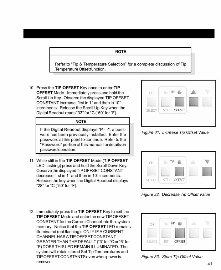
NOTE
Refer to “Tip & Temperature Selection” for a complete discussion of TipTemperature Offset function.
10. Press the TIP OFFSET Key once to enter TIPOFFSET Mode. Immediately press and hold theScroll Up Key. Observe the displayed TIP OFFSETCONSTANT increase, first in 1° and then in 10°increments. Release the Scroll Up Key when theDigital Readout reads “33” for °C (“60” for °F).
NOTE
If the Digital Readout displays "P - -", a pass-word has been previously installed. Enter thepassword at this point to continue. Refer to the"Password" portion of this manual for details onpassword operation.
11. While still in the TIP OFFSET Mode (TIP OFFSETLED flashing) press and hold the Scroll Down Key.Observe the displayed TIP OFFSET CONSTANTdecrease first in 1° and then in 10° increments.Release the key when the Digital Readout displays“28” for °C (“50” for °F).
12. Immediately press the TIP OFFSET Key to exit theTIP OFFSET Mode and enter the new TIP OFFSETCONSTANT for the Current Channel into the systemmemory. Notice that the TIP OFFSET LED remainsilluminated (not flashing). ONLY IF A CURRENTCHANNEL HAS A TIP OFFSET CONSTANTGREATER THAN THE DEFAULT (“3” for °C or “6” for°F) DOES THIS LED REMAIN ILLUMINATED. Thesystem will retain stored Set Tip Temperatures andTIP OFFSET CONSTANTS even when power isremoved.
Figure 31. Increase Tip Offset Value
Figure 33. Store Tip Offset Value
Figure 32. Decrease Tip Offset Value

42
PANEL CONTROLS CONT'D
13. Press the TIP SET Key once. This is TIP SETMode. The TIP SET LED will flash and the DigitalReadout will display the stored Set Tip Temperaturefor the Current Channel. As received from thefactory, the Digital Readout will display “OFF”. Also,if no other operation occurs within 6 seconds, theLED will turn off and the Digital Readout will revert tothe Temperature Display Mode. Pressing the TIPSET Key a second time will immediately place thesystem in the Temperature Display Mode (normaloperation).
14. Plug an auxiliary accessory (if purchased) intoany of the three Aux Power Receptacles (AUX 1,2 or 3). Repeat step #8.
Notice that each subsequent pressing of the CHSELECT Key will illuminate the AUX LED and theChannel LED corresponding to the auxiliarychannel to which the auxiliary accessory isconnected. The sequence in this case would beCH 1 to CH 2 to CH 3 to CH 1 (plus the AuxiliaryLED) to indicate the active Auxiliary Channel(AUX 1) and then back to CH 1.
Figure 34. Display Stored Tip Temp.
Figure 36. Changing Current Channel
Figure 35. Aux. Accessory Connection

43
15. Press the TIP SET Key once again to enter the TIPSET Mode. Press and hold the Scroll Up Key.Observe as the displayed Set Tip Temperatureincreases first in 1°, then in 10° increments (°C or °F).Release the key when the Digital Readout reads 371°C(or 700°F). Immediately press the TIP SET Key onceagain. Observe the Digital Readout as the OperatingTip Temperature reaches 371°C (or 700°F).
16. Press the °F/°C Key several times to observe thealternating illumination of the °F & °C LEDS. Eachsubsequent pressing of the key will turn one LED onand the other off. Also notice as the Digital Readoutchanges to display the Operating Tip Temperature in °Fwhen the °F LED is illuminated and in °C when the °CLED is illuminated.
17. Press the TIP SET Key once to enter the TIPTEMPERATURE SET Mode. Immediately press & holdthe Scroll Down Key. Observe as the displayed TIPSET Temperature decreases first in 1° and then in 10°increments (°C or °F). Release the key when the DigitalReadout displays 343°C (650°F). Immediately pressthe TIP SET Key once again (or wait 6 seconds) and observe the Operating Tip Temperaturedecrease to 343°C (650°F).
Figure 37. Enter Tip Temp. Set Mode
Figure 38. °F To °C Digital Readout
Figure 39. Decreasing Set Tip Temp.

44
PANEL CONTROLS CONT'D
18. Press the TIP SET Key once again and use theScroll Up and Scroll Down Keys to enter your desiredSet Tip Temperature. Immediately press the TIP SETKey to exit the TIP SET Mode. This enters the newSet Tip Temperature for the Current Channel intosystem memory.
NOTE
If a Password has been installed in the system,press the °F/°C Key to reactivate Password pro-tection.
19. Note the Current Channel displayed on the system.Turn the POWER Switch to the OFF (“0”) position.Turn the POWER Switch back to the ON (“1”)position. Using the CH SELECT Key, select thechannel displayed in step #18. Notice that the TIPOFFSET LED is illuminated to indicate that a TIPOFFSET CONSTANT higher than the default ("3" for°C or "6" for °F) has been stored in system memory.
20. Press the TIP OFFSET Key. Notice that the systemhas retained the stored TIP OFFSET CONSTANT.Press the key once again to exit TIP OFFSET Mode.
Figure 40. Changing Set Tip Temperature
Figure 41. Power Off
Figure 42. Storing Tip Offset Value
KBTIPSUD.EPS

45
21. Press the TIP SET Key. Notice that the system hasretained the stored Set Tip Temperature in memory.Immediately press the TIP SET Key once again toexit TIP SET Mode.
22. In order to prevent a handpiece/tip combination frominadvertently operating at an incorrect TipTemperature, a safety feature incorporated within thesystem will prevent retention of a stored TIPOFFSET CONSTANT if a handpiece is disconnected.The TIP OFFSET CONSTANT will return to thedefault value of “3” for °C (“6” for °F). Disconnect thehandpiece connected to the Current Channel.Reconnect the handpiece to the same channel.Notice that the Current Channel changes to the nextActive Channel.
23. Press the CH SELECT Key, as necessary, tochange the Current Channel to the channeldisconnected in step #22.
Figure 43. Store Set Tip Temperature
Figure 44. Handpiece Connection , TMC
Figure 45. Changing Current Channel

46
PANEL CONTROLS CONT'D
24. Press the TIP OFFSET Key. Notice that the TIPOFFSET CONSTANT has now changed to thedefault value of “3” for °C (“6” for °F) and the TIPOFFSET LED turns off. Whenever a channelbecomes inactive, the system memory automaticallyreverts to the default TIP OFFSET CONSTANT.
25. While in TIP OFFSET Mode (TIP OFFSET LEDflashing), use the Scroll Up and Scroll Down Keys toset a desired TIP OFFSET CONSTANT. Press andrelease the TIP OFFSET Key to exit TIP OFFSETMode to store TIP OFFSET CONSTANT in systemmemory.
Figure 46. Tip Offset Default
Figure 47. Adjust Tip Offset Value

47
26. Using the CH SELECT Key, select each ActiveChannel in sequence, making it the Current Channel(temperature information displayed on DigitalReadout). Using the procedures described inprevious steps #10 thru 18 and steps #24 thru 25 asa reference, enter and store desired SET TIPTemperatures and appropriate TIP OFFSETCONSTANTs into system memory. Refer to the “Tip& Temperature Selection System” charts sent withyour unit and the “Tip & Temperature Selection”portion of this manual for more detailed informationon selection of the proper Tip, Handpiece andTemperature Options for your particular application.
NOTE
The PRC 2000 systems incorporate a “Dynamic Offset” feature whichautomatically adjusts the Tip Temperature Offset (based on the entered TIPOFFSET CONSTANT) for any Set Tip Temperature established by theoperator. This ensures the maintenance of true, accurate Tip Temperatures.Simply stated, any operating Tip Temperature displayed on the DigitalReadout will be correct.
Always set the appropriate TIP OFFSET CONSTANT for the selectedHandpiece/Tip combination (listed in the shaded area on the Tip &Temperature Selection System Charts) before entering the desired Set TipTemperature. The Set Tip Temperature + the Dynamically Adjusted TipTemperature Offset value (usually different from the entered Tip OffsetConstant) cannot exceed 489°C (912°F). If this limit is exceeded, thesystem will automatically lower the maximum possible Set (and Operating)Tip Temperature accordingly.
Figure 48. Change Current Channel

48
PANEL CONTROLS CONT'D
24. Press the TIP OFFSET Key. Notice that the TIPOFFSET CONSTANT has now changed to thedefault value of “3” for °C (“6” for °F) and the TIPOFFSET LED turns off. Whenever a channelbecomes inactive, the system memory automaticallyreverts to the default TIP OFFSET CONSTANT.
25. While in TIP OFFSET Mode (TIP OFFSET LEDflashing), use the Scroll Up and Scroll Down Keys toset a desired TIP OFFSET CONSTANT. Press andrelease the TIP OFFSET Key to exit TIP OFFSETMode to store TIP OFFSET CONSTANT in systemmemory.
Figure 46. Tip Offset Default
Figure 47. Adjust Tip Offset Value

49
26. Using the CH SELECT Key, select each ActiveChannel in sequence, making it the Current Channel(temperature information displayed on DigitalReadout). Using the procedures described inprevious steps #10 thru 18 and steps #24 thru 25 asa reference, enter and store desired SET TIPTemperatures and appropriate TIP OFFSETCONSTANTs into system memory. Refer to the “Tip& Temperature Selection System” charts sent withyour unit and the “Tip & Temperature Selection”portion of this manual for more detailed informationon selection of the proper Tip, Handpiece andTemperature Options for your particular application.
NOTE
The PRC 2000 systems incorporate a “Dynamic Offset” feature whichautomatically adjusts the Tip Temperature Offset (based on the entered TIPOFFSET CONSTANT) for any Set Tip Temperature established by theoperator. This ensures the maintenance of true, accurate Tip Temperatures.Simply stated, any operating Tip Temperature displayed on the DigitalReadout will be correct.
Always set the appropriate TIP OFFSET CONSTANT for the selectedHandpiece/Tip combination (listed in the shaded area on the Tip &Temperature Selection System Charts) before entering the desired Set TipTemperature. The Set Tip Temperature + the Dynamically Adjusted TipTemperature Offset value (usually different from the entered Tip OffsetConstant) cannot exceed 489°C (912°F). If this limit is exceeded, thesystem will automatically lower the maximum possible Set (and Operating)Tip Temperature accordingly.
Figure 48. Change Current Channel

50
TIP & TEMPERATURE SELECTION
With any heating system, actual tip temperatures can differ greatly from temperature control settings.PACE’s unique “Tip & Temperature Selection System” allows you to select and maintain True TipTemperatures for any size and type of tip and handpiece using the appropriate TIP OFFSET CONSTANT.Included with your system is a Chart Holder which holds Procedural Instructions, a Quick ReferenceGuide, a Customer Log and Charts for each handpiece currently available from PACE. Follow theprocedure given in the chart marked “Introduction” when using the charts for any particular handpiece.Listed below is the summarized procedure.
PROCEDURE
Select the appropriate Handpiece Chart for your application based on component type and/or procedure(e.g., SMD removal, thru-hole soldering, etc.) and identify the correct tip. Install tip into handpiece andfollow the procedure below.
1. In Tip Temperature Offset (TIP OFFSET) Mode, enter the TIP OFFSET CONSTANT (# inshaded area) corresponding to your selected tip for the channel powering the handpiece.
2. In Tip Temperature Set (TIP SET) Mode, set ANY desired Tip Temperature up to themaximum. The tip will idle at this temperature.
NOTE
The Tip Offset Value is internally calculated and adjusted automatically(based on the TIP OFFSET CONSTANT) so that a True Tip Temperature isalways displayed on the Digital Readout - even when the desired Set TipTemperature is changed.

51
PASSWORD
A password feature of the THERMAL MANAGEMENT CENTER which, when activated, will preventunauthorized alteration of stored System and Channel features listed in Table 1 "Factory Settings". If apassword has been installed, "P - - " will appear on the Digital Readout to prevent the operator fromchanging any of the stored settings. Entry of the correct password at this point will allow the operator toproceed with desired changes. Listed following are procedures for all password entry, change and removaloperations.
INITIAL INSTALLATION OF A PASSWORD
1. Place the POWER Switch in the OFF ("0") position.
2. Press and hold the TIP SET and the °F/°C Keys down.
3. Place POWER Switch in the ON (“1”) position. All theTHERMAL MANAGEMENT CENTER LEDs willilluminate. The Digital Readout will read “888” andchange to read “1 - 0”. This number may be different onyour unit.
Figure 50. Enter Password Mode
Figure 49. Power Off
Figure 51. Digital Readout "888"

52
INITIAL INSTALLATION OF A PASSWORD CONT'D
4. Release the TIP SET and the °F/°C Keys. The systemis now in Password Mode. The Digital Readout willdisplay “PS-” and only the three Channel LEDs plus theAuxiliary LED will remain illuminated signifying that thesystem does not have a Password installed. NOTE: If“P - -” is displayed on the Digital Readout instead of“PS-”, a Password has been previously installed. Referto the “Removing/Changing Password” sectionprocedure.
5. Write down the Password desired. Note that the TIPSET Key may never be the first key of a Password (seestep #6).
Figure 52. Password Status
Figure 53. First Key Not Tip Set Key

53
6. Press any key except the TIP SET Key as the firstkey of the Password.
7. Press any key as the second key of the Password.
8. Press any key as the third (and last) key of thePassword.
The Calibration Mode has been automatically entered and theDigital Readout will now display “CAL”. If no calibrationparameters need to be changed, exit Calibration Mode and goto regular operation by pressing the TIP OFFSET Key.Otherwise, perform calibration now (refer to theCALIBRATION/SYSTEM SETUP section). When finisheddoing calibration, press the TIP OFFSET Key to leave "CAL"Mode and enter Temperature Display Mode (normal operation).
NOTE
The Password is not permanently stored until the Calibration Mode (“CAL”)is exited normally by pressing the TIP OFFSET Key. If the POWER Switchis turned OFF (“0”) while still in the Calibration Mode, the Password will notbe saved.
Figure 54. First Key Not Tip Set Key
Figure 55. Cal Mode

54
REMOVING A PASSWORD
1. Place the POWER Switch in the OFF (“0”) position.
2. Press and hold the TIP SET and the °F/°C Keysdown.
3. Place POWER Switch in the ON (“1”) position. Allthe THERMAL MANAGEMENT CENTER LEDs willilluminate. The Digital Readout will read “888” andchange to read “1 - 0”. This number may be differenton your unit.
Figure 56. Power Off
Figure 57. Enter Password Mode
Figure 58. Digital Readout "888"

55
Figure 59. Stored Password
Figure 60. First Key Not Tip Set Key
4. Release the TIP SET and the °F/°C Keys. The DigitalReadout will now display “P - -” signifying that thesystem is now asking for the operator to enter thePassword previously installed into the system'smemory.
NOTE
If “PS-” is displayed on the Digital Readout instead of “P - -”, a Passwordhas not been previously installed. Refer to the “INSTALLING A PASS-WORD” section of this manual.
5. Press the first key of the Password.
6. Press the second key of the Password.
56
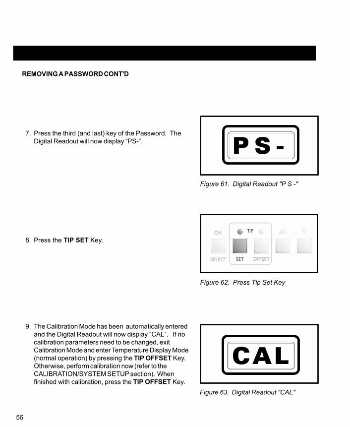
REMOVING A PASSWORD CONT'D
7. Press the third (and last) key of the Password. TheDigital Readout will now display “PS-”.
8. Press the TIP SET Key.
9. The Calibration Mode has been automatically enteredand the Digital Readout will now display “CAL”. If nocalibration parameters need to be changed, exitCalibration Mode and enter Temperature Display Mode(normal operation) by pressing the TIP OFFSET Key.Otherwise, perform calibration now (refer to theCALIBRATION/SYSTEM SETUP section). Whenfinished with calibration, press the TIP OFFSET Key.
Figure 61. Digital Readout "P S -"
Figure 62. Press Tip Set Key
Figure 63. Digital Readout "CAL"

57
Figure 64. Power Off
Figure 65. Password Mode Entry
NOTE
The password is not permanently removed until the Calibration Mode isexited normally by pressing the TIP OFFSET Key. If AC POWER is turnedoff while still in the Calibration Mode, the password will not be removed.
CHANGING THE PASSWORD
1. Place the POWER Switch in the OFF (“0”) position.
2. Press and hold the TIP SET and the °F/°C Keys down.

58
CHANGING THE PASSWORD CONT'D
3. Place Power Switch in the ON (“1”) position. Allthe THERMAL MANAGEMENT CENTER LEDs willilluminate. The Digital Readout will read “888” andchange to read “1-0”. This number may be differenton your unit.
4. Release the TIP SET and the °F/°C Keys. TheDigital Readout will now display “P - -” signifying thatthe system has a Password installed. NOTE: If“PS-” is displayed on the Digital Readout instead of“P - -”, a Password has not been previouslyinstalled. Refer to the “INSTALLING A PASSWORD”procedure.
5. Write down the new Password desired. Rememberthat the TIP SET Key may never be the first key of apassword.
Figure 66. Digital Readout "888"
Figure 67. Digital Readout "P - -"
Figure 68. First Key Not Tip Set Key

59
6. Press the first key of the old Password.
7. Press the second key of the old Password.
8. Press the third (and last) key of the old Password.
9. The Digital Readout will now display “PS-”.
10. Press any key, except the TIP SET Key, as the firstkey of the new Password.
Figure 69. Digital Readout "P S -"
Figure 70. First Key Not Tip Set Key

60
CHANGING THE PASSWORD CONT'D
11. Press any key as the second key of the newPassword.
12. Press any key as the third (and last) key of the newPassword.
13. The Calibration Mode has been automaticallyentered and the Digital Readout will now display“CAL”. If no calibration parameters need to bechanged, exit Calibration Mode and go toTemperature Display Mode (normal operation) bypressing the TIP OFFSET Key. Otherwise, performcalibration now (refer to the CALIBRATION/SYSTEMSETUP section). When finished with calibration,press the TIP OFFSET Key.
NOTE
The Password is not permanently replaced untilthe Calibration Mode is exited normally by press-ing the TIP OFFSET Key. If AC POWER isturned off while still in the Calibration Mode, thenew Password will not be saved.
CLEARING A LOST PASSWORD
1. Place the POWER Switch in the OFF (“0”) positionand disconnect the AC power cord fom the system.
Figure 71. Digital Readout "CAL"
Figure 72. Power Off

61
DANGER
POTENTIAL SHOCK HAZARDThe following steps are to beperformed by qualified servicepersonnel only. Removal of therear panel exposes line voltageparts. Service personnel mustinsure that AC power cord is dis-connected when installing jumperwire (step #5) and disconnectingjumper wire (step #9).
2. Remove the 12 screws securing the Rear Panel to thesystem chassis.
3. Lay the Rear Panel on the work surface exposing theinside of the system.
4. Locate the 2 Pin Header inside the power sourcechassis near the rear and center.
5. Place a jumper wire across the pins.
6. Install the AC power cord. Place the POWER Switchin the ON (“1”) position. The system is now inCalibration ("CAL") Mode.
7. Press the TIP OFFSET Key to exit Calibration ("CAL")Mode. After a few seconds, any password will beremoved.
8. Place the POWER Switch in the OFF (“0”) position.Disconnect the AC power cord.
9. Remove the jumper wire.
10. Replace the rear panel cover using the screws removedin step #2. Install the AC power cord.
Figure 73. Rear Panel Removal
Figure 74. 2 Pin Header
Figure 75. Power Off

62
CALIBRATION
INTRODUCTION
In Calibration (CAL) Mode, you can:
1. Change the Upper & Lower Temperature limits for each channel independently.
2. Set the default temperature scale to °F or °C as desired.
3. Enable or disable the Auto Temperature Setback/Power Down features.
PROCEDURE
1. Place POWER Switch in the “Off” (“0”) position.
2. Press and hold the TIP SET and Scroll Down Keys.
Figure 76. Power Off
Figure 77. Calibration Entry

63
3. Place POWER Switch in the On (“1”) position. All ofthe system LEDS will light. The Digital Readout willread “888” and change to read “1-0”. This number maybe different on your unit.
4. Release the TIP SET and Scroll Down Keys. TheDigital Readout will now display “CAL” and only thethree Channel LEDs will remain lit signifying that thesystem is now in Calibration (CAL) Mode. NOTE: If apassword has been installed, “P - -” will appear on theDigital Readout. Enter the password key sequence todisplay “CAL”.
Figure 78. Digital Readout "888"
Figure 79. Digital Readout "CAL"

64
°F/°C READOUT DEFAULT
5. Press and release the TIP SET Key. The DigitalReadout will display “S - X” (X = “-” or 1-9). Either the°F or °C LED will be on. This is the default temperaturescale of the Digital Readout (e.g., if the °C LED is on,the Digital Readout will display Tip Temperatures andTip Offset values in °C).
6. Press and release the °F/°C Key to change the default.Each subsequent press and release of the key willchange the default.
AUTOMATIC TEMPERATURE SETBACK
7. As received from the factory, “S - -” will be displayedindicating that the Automatic Temperature Setback isturned off. A “1” thru “9” appearing on the right side ofthe Digital Readout indicates time to AutomaticSetback in increments of 10 minutes. For example, “S-3” would indicate that any Active Channel will set backits handpieces’ Set Tip Temperature to 180°C (350°F)after 30 minutes of handpiece inactivity (non-use). Tochange the time period or turn the AutomaticTemperature Setback feature off or on, use the ScrollKeys. Press the Scroll Up Key to increase the timeperiod and/or enable the feature. Press the Scroll DownKey to decrease the time period or disable the feature.
Figure 80. Digital Readout "S - X"
Figure 81. Change Temperature Default
Figure 82. Adjust Setback Time

65
8. Press the TIP SET Key to store the °F/°C default andAutomatic Temperature Setback time value in systemmemory. The Digital Readout will revert to “CAL” andonly the CH 1 LED will remain lit.
AUTOMATIC POWER DOWN
9. The Automatic Power Down feature is enabled when any time period (10 - 90 minutes) forAutomatic Temperature Setback is entered in step #7. If no time period is selected (i.e., "S - -"appears on the Digital Readout), the Automatic Power Down feature is disabled. No additionalsteps are necessary. The Automatic Power Down feature operates when (and only when) allchannels are in Temperature Setback. For example, power to all channels is turned off 90minutes after the last Active Channel’s Tip Temperature is set back.
CHANNEL SECTION
10. The CH 1 LED is now on signifying that Channel 1 is ready to set temperature limits. Performsteps 11 through 17 to calibrate. Change channels as directed and repeat these steps for eachchannel.
Figure 83. Store Temperature Default

66
TEMPERATURE LIMITS
NOTE
All temperature limits areentered and stored in systemmemory in degrees F.
LOWER TEMPERATURE LIMIT
11. Press and release the TIP SET Key. The DigitalReadout will now display “L-X” (X = 1-9). This is thestored value of the Lower Temperature Limit inincrements of 100°F. For example, “L-5” is displayedindicating a lower temperature limit of 500°F.
12. Press Scroll Keys as necessary to increase (ScrollUp Key) or decrease (Scroll Down Key) the LowerTemperature Limit.
13. Press and release the TIP SET Key.
Figure 84. Digital Readout "L - X"
Figure 85. Change Lower Temp. Limit
Figure 86. Press Tip Set Key

67
UPPER TEMPERATURE LIMIT
14. The Digital Readout now displays “H-X” (X = 1-9).This is the stored value of the upper temperature limitin increments of 100°F.
15. Press Scroll Keys as necessary to increase (ScrollUp Key) or decrease (Scroll Down Key) the uppertemperature limit.
16. Press and release the TIP SET Key. The DigitalReadout will now display “CAL”. The next ActiveChannel now becomes the Current Channel.Perform steps 11 through 16 to set upper and lowertemperature limits for the other channels (CH 1, CH2, CH 3, AUX 1, AUX 2 and AUX 3). After allchannels have been calibrated, you may exit theCalibration (CAL) Mode by pressing and releasingthe TIP OFFSET Key.
Figure 87. Digital Readout "H - X"
Figure 88. Change Upper Temp. Limit
Figure 89. Press Tip Set Key

68
UPPER TEMPERATURE LIMIT CONT'D
17. All values, features and defaults entered during thecalibration are now stored in memory and all Set TipTemperatures are turned “OFF”. All Channel TIPOFFSET CONSTANTs are set to the default value of “3”for °C (“6” for °F).
TEMPERATURE SETBACK
The PRC 2000 system is equipped with a Temperature Setback feature which, when enabled, will preservetip life and reduce energy consumption.
ACTIVATION
There are two ways in which the system will enable the Temperature Setback feature.
1. AUTOMATIC OPERATION - The system memory can be programmed so that each ActiveChannel will automatically and independently set back its Set Tip Temperature to 180°C (350°F)after a selected period (10-90 minutes) of handpiece inactivity. See “Calibration” section fordetails on programming this feature.
2. MANUAL OPERATION - The operator can manually force the system to place all ActiveChannels in Temperature Setback by performing the following procedure.
a) Press and hold the Scroll Down Key.
Figure 90. Digital Readout "OFF"
Figure 91. Forcing Temp. Setback

69
b) Press the Scroll Up Key.
c) Release both keys.
OPERATION
1. Temperature Setback for each channel is indicated by the following.
a) The Current Channel LED will flash off once each 2 second period when that channel is inTemperature Setback Mode.
b) Any Active, non-Current Channel LED will flash on once each 2 second period when thatchannel is in Automatic Temperature Setback Mode.
2. Any Inactive Channel will not enter Temperature Setback Mode.
3. Any Active Channel whose Set Tip Temperature is less than 180°C (350°F) will enterTemperature Setback Mode but will remain at its original Set Tip Temperature.
EXITING AUTOMATIC TEMPERATURE SETBACK MODE
Figure 92. Temp. Setback Entry

70
Listed below are 4 different ways to exit Temperature SetbackMode.
1. For any individual channel, perform the followingoperation.
a) Press and release the CH SELECT Key until theSetback Channel becomes the Current Channelshown on the Digital Readout.
b) Press and release the Scroll Up Key.
c) The system will now restore the previous Set TipTemperature of the Current Channel.
d) Observe the Digital Readout as the Operating TipTemperature increases to the Set Tip Temperature(if above 180°C (350°F)). For optimumperformance, DO NOT attempt to use the attachedhandpiece until Set Temperature is achieved.
2. For any individual channel, the attached handpiecemay be disconnected and reconnected. Thepreviously stored Set Tip Temperature will be restoredas in method #1 but the Tip Temperature Offset value
Figure 93. Changing Channel
Figure 94. Restore Previous Tip Temp.

71
will change to the default value of “3” for °C (“6” for°F).
To exit Temperature Setback Mode for all Channels, do eitherof the following.
3. Press and hold the Scroll Down Key; press theScroll Up Key. Release both keys. This is thepreferred method.
4. Method "3" is preferred but you can turn the POWERSwitch “OFF” (0) and then back “ON” (1). Set TipTemperature and TIP OFFSET CONSTANTs will besimultaneously restored on all channels.
FACTORY DEFAULT
As received from the factory, the system will not go intoAutomatic Temperature Setback. To enable this feature, referto the “Calibration” portion of this manual.
Figure 95. Exit Setback Mode
Figure 96. Power Off

72
AUTOMATIC POWER DOWN
The Automatic Power Down feature of the PRC 2000 system is a safety feature which removes power fromall channels 90 minutes after all Active Channels have entered the Temperature Setback Mode. Thisfeature is not programmable and is automatically enabled when all Active Channels are in the TemperatureSetback Mode.
OPERATION
When all Active Channels have entered Automatic Temperature Setback Mode, a 90 minute timer withinthe system circuitry will start running.
1. If the system has no Active Channels (no connected handpieces), Automatic Shutdown will notoccur.
2. If any key is pressed during the 90 minute time period, the timer is reset. Timer will not starttiming out again until all Active Channels are in Temperature Setback Mode.
3. During the last minute before the 90 minutes expire, an audible tone will occur every 4 secondsto alert the operator.
4. At the end of the 90 minute period, the system will enter the Power Down Mode. Power isremoved from all channels, all Channel LEDs will stop flashing and the Digital Readout willdisplay a flashing “OFF”.
EXITING POWER DOWN MODE
Power Down can be exited with all channels returning to normal operation by pressing any key or byturning the POWER Switch OFF (“0”) and then back ON (“1”).

73
DIGITAL READOUT MESSAGE CODES
Listed below are message codes and a description of each which may be displayed on the DigitalReadout during the Calibration procedure.
DISPLAYMESSAGE DESCRIPTION
E-1,E-2,E-3 OR E-4 Refer to "CORRECTIVE MAINTENANCE"section.
CAL Indicates that system is in the Calibration Mode.
H-XReady to accept new Upper Temperature Limitsetpoint for this channel, where: X is limit inhundreds of degrees F.
L-XReady to accept new Lower Temperature Limitsetpoint for this channel, where: X is limit inhundreds of degrees F.
OFF Setpoint for this channel is below lowertemperature setpoint limit.
S-- Indicates Automatic Temperature Setback isdisabled.
S-X Indicates Automatic Temperature Setback isenabled, where: X is tens of minutes to Setback.
PS- Waiting for operator to input new Password tolock system.
P--Operator must enter Password to unlock systemand change operating temperatures,temperature limits, or tip temperature offsets.
Table 2. Digital Readout Message Codes

74

75
QUICK REFERENCE - SYSTEM OPERATION
The Quick Reference Charts shown may be used as a guide for quickly changing any particularparameter stored within the THERMAL MANAGEMENT CENTER of the PRC 2000 system. Locatethe parameter you wish to change in the column marked “ACTION” and follow the simple instructionsgiven under “Procedure”. Remember that if a password has been stored in the system, the passwordkey sequence must be entered before making any changes.
ACTION PROCEDURE
SELECT CURRENTCHANNEL
PRESSKEY
CHANGE SCALE°F/°C READOUT
PRESSKEY
ADJUST TIPOFFSET CONSTANT
PRESSKEYS
ADJUST SET TIPTEMPERATURE
PRESSKEYS
Table 3. Quick Reference Chart
CHSELECT
˚F
˚C
or
or[ ][ ]
TIPOFFSET
TIPSET
TIPSET
TIPOFFSET

76
ENTERCALIBRATION(CAL) MODE
PRESS & HOLD POWER ON RELEASE AFTER 3 SECONDS
SET DEFAULTTEMP SCALE(°F/°C) **
PRESSKEYS
CHANGE LOWERTEMP LIMIT **
PRESSKEYS
CHANGE UPPERTEMP LIMIT **
PRESSKEYS
AUTOTEMP SETBACK**
PRESSKEYS
AUTO POWERDOWN ** Automatically enabled or disabled with AUTO TEMP SETBACK feature.
** SYSTEM MUST BE IN CALIBRATION (CAL) MODE.
TIPSET
TIPSET
TIPSET
CHSELECT
TIPSET
or TIPSET
TIPOFFSET[ ]
[ ]TIPSET
or TIPSET
TIPOFFSET
TIPSET
TIPSET
˚F
˚C
TIPSET
CHSELECT
TIPSET
TIPSET
TIPOFFSET
TIPSET
TIPSET
or TIPOFFSET
(PressTwice)
Table 3. Quick Reference Chart Continued
++
[ ]
ACTION PROCEDURE
TIPSET

77
M A N U A LSETBACK ONALL ACTIVEC H A N N E L S
PRESS & HOLD RELEASE AFTER 1 SECOND
E X I TSETBACK ONA L LA C T I V EC H A N N E L S
PRESS & HOLD RELEASE AFTER 1 SECOND
E N T E RP A S S W O R DM O D E
PRESS & HOLD POWER ON RELEASE AFTER 1 SECOND
I N S T A L LPASSWORD **
P R E S SK E Y S
C H A N G EPASSWORD **
ENTER OLD PASSWORD ENTER NEW PASSWORD
P R E S SK E Y S
R E M O V EPASSWORD **
ENTER PASSWORD
P R E S SK E Y S
**
TIPSET
NOTSETKEY
ANYKEY
˚F
˚C+
+
+
ANYKEY
TIPOFFSET
TIPSET
TIPOFFSET
ANYKEY
ANYKEY
TIPOFFSET
TIPSET
˚F
˚C+
+
+
KEY3
NOTSETKEY
KEY2
KEY1
KEY1
KEY2
KEY3
ACTION PROCEDURE
SYSTEM MUST FIRST BE PUT IN PASSWORD MODE.INITIATE PROCEDURE WITHIN 5 SECONDS OR SYSTEMWILL REVERT TO NORMAL OPERATION.
Table 3. Quick Reference Chart Continued

78
FOOT PEDAL
The foot pedal may be used with the PRC 2000 system intwo different manners as described below.
1. FOOT PEDAL Receptacle - Connection of the footpedal to this receptacle will allow the Pulse Heat(PH), Pulse Plate (PP), MicroChine (MC) and Pik &Paste (PD) features of the system to be actuated bythe foot pedal. Electrical connection from the footpedal to each feature is selected by positioning ofthe FOOT PEDAL Selector Switch.
2. THERMAL MANAGEMENT CENTER - The foot pedalmay be connected to any unused Output Receptacle(CH 1, 2 or 3 or AUX 1, 2 or 3) on the rear panel ofthe system. Depressing of the foot pedal whenconnected in this manner, will activate the vacuumpump to create vacuum at the SNAP-VAC Port or airpressure at the Controllable PRESSURE Port.
Figure 98. Foot Pedal Selector Switch
Figure 97. Foot Pedal Connection
Figure 99. Aux. Foot Pedal Connection

79
PIK AND PASTE
Located in the middle of the front panel of the system power source, this portion of the PRC 2000 providesboth a vacuum pick/placement capability (PIK) and a dispensing capability (PASTE) for use with a varietyof solder cremes, high viscosity fluxes and adhesives. Refer to the “Capabilities” portion of this manual fora complete description of this feature. Following are the Set-Up and Operation instructions for eachfeature.
Fitting Air Hose
PASTE DISPENSER
SET-UP
1. Install the Dispenser Cubby (PACE P/N 6019-0038)provided with the system and install onto the left sideof the system power source chassis. Assemblyinstructions are enclosed with the cubby.
2. Locate the Paste Dispenser Kit (PACE P/N 6993-0152) provided with the system.
3. Attach the ridged end of the male quick connecthose mount Fitting to the Air Hose.
4. Insert the male quick connect hose mount Fitting(attached to Air Hose) into the female PASTE DISPPort.
Figure 102. Paste Dispense Connection
Figure 101. Air Hose Connection
Figure 100. Dispenser Cubby Mounting

80
SET-UP CONT'D
5. Slide the Hose Clamp over the free end of the AirHose. Push clamp back 1 inch from the end of theAir Hose.
6. Attach the free end of the Air Hose to the nipple onthe Barrel Adapter (10 cc adapter is supplied).
7. Secure the Air Hose to the Barrel Adapter by slidingthe Hose Clamp down over the Air Hose/BarrelAdapter connection and screwing clamp down tosecure in position.
8. Attach the Barrel Adapter to a barrel prefilled withmaterial (not supplied). Place the barrel in theDispenser Cubby.
9. Insure that the foot pedal is connected to the FOOTPEDAL Receptacle on the rear panel.
10. Set the FOOT PEDAL Selector Switch to the “PD”position.
HoseClamp
Air Hose
Barrel Adapter
Figure 104. Foot Pedal Select. Switch
Figure 103. Barrel Adapter Connect.

81
NOTE
When the Foot Pedal Selector Switch is set in the PD position, the dispensepump will run for a few seconds to provide a reservoir of pressurized airnecessary for proper dispensing. The pump will also cycle every 2 minutesto maintain reservoir pressure.
OPERATION
PACE recommends that the operator become familiar with the operation of the dispenser by first applyingthe material to a piece of paper or scrap PC board. Use this method to obtain the desired results for eachdispensing material and application.
MATERIALS USED FOR DISPENSING
CAUTION
Always refer to the Material Safety Data Sheet supplied with the material asa guide for proper handling and safety precautions.
Barrels prefilled with solder creams and brazing pastes of 400,000 to 600,000 centipoise viscosity may bedispensed using the needle size selections provided with your system.
NOTE
DO NOT attempt to dispense materials with viscosity levels lower than400,000 centipoise. Low viscosity materials will not dispense properly.

82
MATERIAL LOADING
PACE recommends the use of prefilled barrels whenever practical to minimize any handling or safetyprecaution requirements. When loading is required, adhere to all precautions recommended by thematerial manufacturer. Refer to the Material Safety Data Sheet supplied with each material for informationon important safety procedures and a listing of any toxic chemical elements.
NOTE
To assure consistent dispensing, fill the barrel to a level of no more than 2/3 of the barrel capacity.
Loading of high viscosity fluids may be accomplished using any of a number of available loading systems.

83
ITEMNO. DESCRIPTION
PARTNUMBER
1 Dispenser Tip, .023" I.D., Pink (pkg. of 5) 1121-0409
2 Dispenser Tip, .020" I.D., Purple (pkg. of 5) 1121-0410
3 Dispenser Tip, .016" I.D., Blue (pkg. of 5) 1121-0411
4 Dispenser Tip, .013" I.D., Orange (pkg. of 5) 1121-0412
Table 4. Available Dispenser Tips
TIP SELECTION
Selection of the proper tip for the application is essential to obtain the optimum deposition rate andamount. Check the specifications of the material manufacturer for recommended tip sizing. The tip sizeand duration of the dispense cycle determine amount of material deposition (dot or bead size). Dispenseseveral dots (or beads) onto a piece of paper or scrap PC board to check for desired results.
NOTE
Never install a clogged tip. The tip may be clogged with material used in aprevious application. Install a new tip and discard after the requireddispensing operation is completed.
Listed below are the four tip sizes available from PACE.

84
DISPENSING MATERIAL
The operator may select the Continuous (CONT ) or TIMED Mode of operation.The CONT Mode allows the operator to dispense the material for as long as the foot pedal remainsdepressed. The TIMED/CONT Switch must be placed in the CONT position for use in this mode. Thismode is recommended for use when dispensing a continuous bead of material.The TIMED Mode allows the operator to select a dispense time of 0.1 to 10 seconds as determined by thePASTE (DISP) Timer Control. The TIMED/CONT Switch must be placed in the TIMED position for use inthis mode. Use of this mode is recommended for all dot dispensing applications.Follow the procedure below to obtain proper results.
1. Insure that the proper material and tip have beeninstalled.
2. Set the TIMED/CONT Switch for the mode of operationdesired. Set the switch to CONT for continuousoperation or TIMED for timed operation.
3. If in the TIMED Mode, set the PASTE (DISP) TimerControl to the desired dispense time period.
Figure 105. Timed/Cont Switch
Figure 106. Paste Disp Timer

85
4. Holding the barrel as shown (at a 45°angle to the work), rest the tip on apiece of paper and dispense a smallamount of material. This initialdispensing will fill the tip withmaterial.
5. Wipe any material residue from theend of tip.
6. Hold the barrel as shown over thework area.
7. Depress the foot pedal to dispensematerial. The dispense cycle willremain on in the CONT Mode untilthe foot pedal is released. In theTIMED Mode, the cycle will continuefor the period of time selected on thePASTE DISP Timer Control. Thepump will turn on periodically tomaintain reservoir air pressure. ThePASTE DISP LED will illuminatethroughout the dispense cycle andwhile the paste pump is running.
8. Place barrel in Dispenser Cubby when dispensing operation is complete.
NOTE
Condensation may occur in the air hose after extended use. This is anormal occurrence.
Figure 107. Paste Dispensing

86
DISPENSING SUGGESTIONS
1. Dispose of all tips and barrels after use. Always use new tips and barrels to preventcontamination, insure cleanliness and provide consistent, repeatable material deposition.
2. When dispensing different dot sizes, select a tip/time combination which dispenses small dots.These small dots may be dispensed in multiples to provide the deposition amount required.Use of the feature in this manner can eliminate frequent tip changes and dispense cycle timeadjustments.
3. In situations where the metal tip may scratch or damage the work, install a short section ofheat shrinkable tubing or teflon sleeving. The tubing (or sleeving) should extend 1.5 mm (1/16")past the tip end.
4. Keep all dispenser components clean to prevent clogging and/or irregular deposition.
VACUUM PICK
SET-UP
1. Locate the Pik-Vac (P/N 7027-0001-P1) and the Vacuum Cup Kit (P/N 6993-0154) supplied withthe system.
2. Attach the ridged end of a male quick connect hosemount Fitting to each end of the Air Hose.
Air HoseFitting
Figure 108. Air Hose Set-Up

87
3. Attach one male quick connect hose Fitting(with attached Air Hose) to the rear of thePik-Vac Handpiece.
4. Insert the other male quick connect hoseFitting (with attached Air Hose) into the PIK-VAC Port.
5. Attach the Metal Vacuum Tip to the end ofthe Pik-Vac Handpiece.
Figure 110. Pik-Vac Power Switch
OPERATION
1. Use of the Metal Vacuum Tip without a Vacuum Cup attached for removal/replacement of verysmall component works well but for larger components, install one of the supplied VacuumCups onto the tip. For best results, use a size slightly smaller than the body of the componentto be removed or placed. For very large components, use the largest Vacuum Cup.
2. Place the PIK-VAC Power Switch in the “ON” (1)position to activate vacuum at the handpiece. The PIK-VAC LED will illuminate whenever the swich is “ON”.
3. Grasp the handpiece as you would a pen with theVacuum Cup (or tip) pointing down and the VacuumControl Port (refer to illustration on following page)pointing up.
Figure 109. Pik-Vac Set-Up

88
OPERATION CONT'D
4. Place the Vacuum Cup and/or the Metal Vacuum Tip gently onto the top surface of theComponent body. Exercise caution to avoid bending of leads on fine pitch devices.
5. Place one finger over the Vacuum Control Port. Vacuum is now being applied to theComponent body.
6. Gently lift the Component off the PC Assembly (removal operation) or out of the componentholder (placement operation).
7. Lower the Component gently into position onto the PC Assembly (placement operation) orcomponent holder (removal operation).
8. Lift finger or gently slide finger back from the Vacuum Control Port to release the Component.
9. Place the PIK-VAC Power Switch in the “OFF” (0) position when all Component handlingoperations are completed.
Pik-Vac Handpiece
VacuumControlPort
Vacuum Cup
PC Assembly
Component
Figure 111. Pik-Vac Operation

89
MICROCHINE
The PACE MicroChine handpiece has a number of unique features which are not available in any othermotorized, hand-held machining tool. The user is provided with a broad range of machining capabilitiesrequired in the repair, rework, modification, prototyping and manufacturing of printed circuit boards andelectronic assemblies.This lightweight, variable speed, static dissipative, hand-held machining instrument offers the user aprimary handpiece with the torque and adjustable rotational speed needed to perform a number ofcontrolled drilling, milling and abrading tasks under varying loads.The Probe Brake feature was developed to help you when repairing multilayer printed circuit boards. Inuse, a lead is connected between the PROBE BRAKE Receptacle on the front panel of the power sourceand a surface or inner layer conductor (land, trace etc.) on the circuit board. During excavation or drillingtasks when the MicroChine drill or mill contacts this desired conductor, the brake circuit is activated andstops the motor instantly. This allows very accurate and precise nondestructive excavation on multilayerassemblies to the exact depth required.The MicroChine Status Indicator LED illuminates Green in color when the MicroChine handpiece isactivated, Amber in color in maximum torque mode and Red in color when Probe Brake circuit isactivated. Electrical power input can be controlled with the integral finger switch conveniently located inthe handpiece or with the foot pedal.
SET-UP
1. Insure that the POWER Switch is in the "ON"position.
2. Connect the MicroChine handpiece power cableconnector to the MicroChine PowerReceptacle.
Figure 112. MicroChine Attachment

90
SET-UP CONT'D
3. Adjust the MicroChine Variable Speed Control to thedesired rotational speed. Speeds are available from2500 to 10,000 R.P.M. On any task, start with alower speed and increase it within your control.
4. Select and attach the desired drill, mill or abrasivetool for the task at hand. Insert a small drill bit intothe access hole in the MicroChine housing and shaftto lock the shaft in position when removing orinstalling a tool.
5. There are two power switching options, the fingerswitch on the handpiece, or the foot pedal control.When use of the foot pedal is desired, the pedalmust be attached to the FOOT PEDAL Receptacleat the rear panel of the system power source.
Figure 113. MC-65 Speed Control
Figure 114. Tool Attachment
Figure 115. Foot Pedal Connection

91
6. Set the FOOT PEDAL Selector Switch to theMicroChine (MC) position when foot pedal actuation isdesired. In this mode either the finger switch on thehandpiece or the foot pedal can actuate theMicroChine.
7. Connect the Probe Brake Lead jack to the PROBEBRAKE Receptacle and the clip end to a conductor(which has continuity with the conductor (s)) you wantto protect. See “Workpiece Grounding”.
Figure 116. Pedal Selector Switch
Figure 117. Probe Brake Attach.

92
Figure 118. Workpiece Grounding
PROBE BRAKE OPERATION
The MicroChine’s Probe Brake feature instantly stops all rotary machining at a selected layer depth fornondestructive multilayer repair.In use, the Probe Brake cable is attached to the PROBE BRAKE Receptacle on the front panel of thesystem power source. The opposite end of the Probe Brake cable must be connected to a connector pin,component lead, or a soldered-on extension of the circuit board assembly. The connection point musthave electrical continuity with the internal conductor to be repaired. A schematic diagram or layoutartwork of the printed wiring assembly (PWA) is a great aid in locating the most effective connection pointfor the Probe Brake cable. The electronic Probe Brake circuit stops the MicroChine instantly when theworking drill or mill makes contact with the internal layer of circuitry, in continuity with the Probe Brakelead, and the Status LED illuminates Red in color. Once the brake circuit has stopped the motor, thefinger switch or foot pedal must be released before the motor can be started again.
WORKPIECE GROUNDING
The Probe Brake may activate prematurely if the workpiece is attached directly to ground. The ProbeBrake circuit operates when a connection is made between the MicroChine bit and the conductor to whichthe Probe Brake Lead clip is attached; a low current flows through this connection to activate the ProbeBrake. Low resistance to ground or high capacitance in the workpiece circuit connected to the ProbeBrake lead may activate the electronic sensing circuitry, in continuity with the Probe Brake lead, in thesystem power source. In this case, PACE recommends the use of the PROBE BRAKE Receptacle toground the workpiece. To prevent electrostatic build-up, this receptacle provides an impedance of 1,000ohms to ground.

93
PULSE PLATE
The PACE PRC 2000 system provides the DC electrical power, voltage level control power receptacles andLED indicator for controlled miniature plating. The LED indicator illuminates Green during normaloperation and Red in short circuit or over current conditions.Electronic current sensing and switching is built into the pulse plating power supply. This innovativecapability protects the workpiece from burning and from electrical arcing should the carbon electrodebecome exposed through the cotton swab during the swab plating process.
SET-UP
1. Set the POWER switch to the “ON” (1) position.
2. Set FOOT PEDAL Selector Switch to the PULSEPLATE (PP) position.
Figure 119. Power On
Figure 120. F.P. Selector Switch

94
SET-UP CONT'D
3. Insure that the foot pedal is attached to theFOOT PEDAL Receptacle on the rear panel ofthe power source.
4. Place foot pedal in a convenient position on the floor beneath the workstation.
5. Open the Model PE-210 SwaPlater Kit and study the enclosed operation manual if you are notfamiliar with the system.
6. Remove the two power cords from the SwaPlater case.
7. Attach the Swatplater power cords to the PULSE PLATE Outputs. Connect the Black powercord to the Black (-) receptacle and the Red power cord to the Red (+) receptacle.
8. Set the PULSE PLATE Output Control to the proper voltage for the plating task required. SeeSwaplater Model PE-210 Operation and Maintenance Manual for complete details on platingprocedure.
Figure 121. Foot Pedal Connection

95
Figure 122. Pulse Plate Set-Up

96

97
PULSE HEAT
Located on the extreme left side of the PRC 2000 system, the PULSE HEAT section features a poweroutput which provides controlled temperature ramp-up to solder reflow and rapid cool down. Thiscontrolled temperature ramp-up helps reduce the risk of thermal shock damage to components andsubstrates in combination with other measures such as preheating with the PACE HotSpot. A variety ofrapid connect/disconnect handpieces allow the operator to perform many different SMD removal/replacement tasks which may be required for any particular repair process. Refer to the “Capabilities”portion of this manual for a complete description ofPULSE HEAT functions.
SET-UP
1. Install the Redi-Rak handpiece storage holderonto the top of the system power source.Complete installation instructions are includedwith the Redi-Rak.
2. Insure that the foot pedal connector plug hasbeen connected to the FOOT PEDALReceptacle located on the rear panel of thepower source.
3. Set the PULSE HEAT Output Control to “0”.
Figure 124. Pulse Heat Control
Figure 123. Foot Pedal Connection

98
SET-UP CONT'D
4. Attach the Universal Power Cord to thePULSE HEAT Outputs as shown.
5. Attach the proper tip for the task at hand, tothe selected handpiece. Refer to the PulseHeat Reference Guidelines for recommendedtip/handpiece selection and PULSE HEATOutput Control settings.
6. Attach selected handpiece to the UniversalPower Cord as shown.
7. Insure that the PULSE HEAT Output Controlis adjusted to “0”.
Figure 126. Handpiece Attachment
Universal Power Cord
Figure 125. Universal Power Cord

99
Figure 128. Pulse Heat Output
Figure 127. Pedal Selector Switch
OPERATION
1. Set the FOOT PEDAL Selector Switch on the systemfront panel to the Pulse Heat (PH) position.
2. Press foot pedal and adjust the PULSE HEAT OutputControl. Increase output level until selected tip heatsto desired level. The Green colored Pulse Heat LEDwill remain illuminated as long as the foot pedal isdepressed.
CAUTION
Overheating and premature failure of tips may result if a high level of poweris applied and/or the tip is not in direct contact with a solder joint(s). In mostcases, the tip should not be heated unless in contact with a solder joint(s).
3. Refer to handpiece manual for recommended component removal/replacement procedures.

100
COMPONENTTYPE OPERATION
# LEADSOR
SIZE
TIPUSED
TIPOUTLINE
OUTPUTLEVEL
PLCC(J LEAD)
REMOVAL
18 1121-0294 718-DRAM 1121-0372 7
20 1121-0295 728 1121-0296 832 1121-0348 944 1121-0297 10
REPLACEMENT
18 1121-0298 320 1121-0298 328 1121-0300 344 1121-0299 3
EXTENDEDLEAD
REPLACEMENT
Sngl. Point 6000-0008 3
0.270" 1121-0298 3
0.540" 1121-0299 3
0.440" 1121-0300 3
CHIPCOMPONENT
REMOVAL&
REPLACEMENTVARIABLE 1121-0286 5
REFERENCE GUIDELINES
The PULSE HEAT Output Control reference guidelines listed in the table below are recommended byPACE as base reference parameters only. In each application, PULSE HEAT Output Control adjustmentsmay be necessary. Start with the applicable setting listed below and increase output level in smallincrements until desired results are achieved.
Table 5. Pulse Heat Reference Guidelines

101
CAUTION
For continuous use, the Output Level settings listed in Table 5 are themaximum recommended values. Exceeding these levels for extendedperiods may sometimes cause the handle to get hot.
COMPONENTTYPE OPERATION
# LEADSOR
SIZE
TIPUSED
TIPOUTLINE
OUTPUTLEVEL
SOT
REMOVAL&
REPLACEMENT3 1121-0269 7
SOIC
REMOVAL
8 1121-0269 614, 16 1121-0271 6.5
20 1121-0270 6.524, 28 1121-0293 6.5
CONNECTORTERMINAL
SOLDERING
REMOVAL&
REPLACEMENTANY
1121-0301 6
1121-0009 6
1121-0006 6
COATINGREMOVAL REMOVAL
POLY U6000-0009
2EPOXY 2.5
WIRESTRIP REMOVAL
PVC, RBR1121-0003
2 - 3TEFLON 3 - 6
Table 5. Pulse Heat Reference Guidelines Cont'd

102

103
VISIFILTER ELEMENT REPLACEMENT
Follow the procedure listed below to replace the VisiFilter element when it becomes clogged ordiscolored.
1. Disconnect the handpiece air hose by gently turningand pulling the coupled Fittings.
2. Disconnect the Visifilter and hose assembly from thePower Source by gently turning and pulling the maleFitting inserted into the SNAP-VAC Port.
3. Disconnect VisiFilter from both attached 1 inch airhoses by gently turning and pulling the VisiFilter whileholding each of the hoses.
4. Separate the 2 plastic housing halves of the VisiFilter inthe following manner.a) Grasp the VisiFilter in the palm of the hand with the
Male Nib (air hose connection) marked "FLOW IN"facing you.
b) Pull against one of the Wing Tabs while pulling onthe Male Nib with the free hand to open theinterconnection of the plastic housings at that WingTab.
c) Pull against the second Wing Tab while pulling on theMale Nib to open the remaining interconnection andseparate the plastic housings.
5. Remove the old or discolored Element and discard.
6. Insert the replacement VisiFilter Element into thehousing marked "FLOW IN". Center the Element inthe housing well.
7. Squeeze the 2 plastic housing halves together using 4plastic Bumps on the housing marked "FLOW OUT" aspressure points. The 2 plastic housings will snaptogether and lock the VisiFilter Element in position.
8. Reconnect the 1 inch air hoses (removed in step 3) tothe VisiFilter.
9. Attach VisiFilter and hose assembly to Power Source byinserting male Fitting into the SNAP-VAC Port.
Figure 129. VisiFilter Element Replacement

104
HANDPIECES
Use the Digital Readout Message Codes ("E-1" & "E-2") listed on Table 6 (under "POWERSOURCE") as a guide to pinpointing any malfunction associated with the handpiece. Refer toOperation and Maintenance Manual applicable to handpiece for instructions on troubleshooting thatparticular handpiece. The following "Heater Assembly Checkout Procedures" are applicable to allPACE SensaTemp handpieces except for the TT-65 ThermoTweez and DTP-80 Dual ThermoPikhandpieces. Refer to either of the TT-65 manuals (P/N 5050-0300 or 5050-0336) for troubleshootingprocedures pertinent to that handpiece.
Figure 130. Handpiece Connector Plug

105
NOTE
Perform the "Heater Assembly Checkout Procedures" shown below with thehandpiece (and heater) at room temperature. If the handpiece is warm,resistance reading will be different from those shown in the table below.
SYMPTOM CHECKOUT PROCEDURE CAUSE SOLUTION HEATERSPECIFICATIONS
No heat Check resistance - Pin 2 to Pin 5.Refer to "Heater Specifications"column. If resistance is high - - Open Heater
Replace HeaterAssembly.
SX-70
SP-1A
SP-2A
TP-65
TJ-70
= 8 - 10 ohms
= 10 - 12 ohms
= 8 - 10 ohms
= 9 - 11 ohms
= 6 - 8 ohms
Check resistance - Pin 3 to Pin 6.If circuit reads open - - Open Sensor
Replace HeaterAssembly.
Handpieceoverheating
Check resistance - Pin 3 to Pin 6.Resistance should be 110 ohms.If resistance reading is less than105 ohms - - Shorted Sensor
Replace HeaterAssembly.
Fuse blowswhen unit isturned on.
Check resistance - Pin 2 to Pin 5.Refer to "Heater Specifications"column.If resistance is low - - Solder short in
Handpiece.
Remove Short.Replace HeaterAssembly & Fuse F1.
Shorted Heater Replace HeaterAssembly & Fuse F1.
No Groundon Tip.
Check resistance - Pin 4 to aNEW Tip. Resistance should beless than 2 ohms.If not - - Oxidation buildup
in Heater Bore.
Clean Heater Boreusing appropriate wirebrush.
Defective Heater Replace HeaterAssembly.
Table 6. Heater Assembly Checkout Procedures

106
POWER SOURCE
SYMPTOM PROBABLE CAUSE SOLUTION
Digital Readout is blank.No functions on system.
Blown Fuse (F1) Replace Fuse F1 located on rear ofPower Source in the AC Receptacle.
Digital Readout is blank.Some functions work.
Low AC line voltage. Check line voltage.
Microprocessor pcb defect. Contact PACE Service Department.
E-1 displayed on DigitalReadout.
All Channels are unpluggedon Thermal Mgmt. Center.
Plug handpiece into CH 1, CH 2 OR CH3.
Open sensor in handpiece. Refer to handpiece Operation Manualfor Corrective Maintenance procedures.
E-2, E-3 or E-4 displayed onDigital Readout.
Defective heater assemblyin handpiece.
Unplug all handpieces. Plughandpieces back in one at a time.When defective handpiece isconnected, "E" code will be displayed.Refer to handpiece Operation Manual.
No heat on handpiece(s) atThermal Management Center.
Open heater. Refer to handpiece Operation Manual.
Blown 12 Amp Fuse. Replace 12 amp Fuse located on rearof Power Source.
Handpieces connected toAUX receptacles. SP & SXseries handpieces are notAUX compatible.
Disconnect incompatible handpiecesfrom AUX Receptacles. Connect toPower Receptacles on front panel.
Damaged PowerReceptacle.
Contact PACE Service Department.
System overload. Check fordefective handpiece.
Disconnect defective handpiece.220 Volt version only: Overtemp cutoutin transformer may open. Allowtransformer to cool.
Microprocessor pcb defect. Contact PACE Service Department.
Table 7. Corrective Maintenance, Power Source

107
SYMPTOM PROBABLE CAUSE SOLUTION
Foot Pedal does not activatevacuum or air pressure forThermal Management Center.
Foot Pedal connected toincorrect receptacle forThermal Mgt. Center motorpump activation.
Connect Foot Pedal to any spare AUXPower Receptacle on ThermalManagement Center.
Defective motor pump. Contact PACE Service Department.
Microprocessor pcb defect. Contact PACE Service Department.
Keys on ThermalManagement Center don'tfunction properly.
Key caps binding. Clean and/or adjust Key caps.
Display pcb misaligned ordefective.
Contact PACE Service Department.
Microprocessor pcbdefective.
Contact PACE Service Department.
Cannot adjust Offset or SetTip Temperature on ThermalManagement Center. DigitalReadout displays "P--".
System is requestingPassword entry.
Enter Password.
Operator forgot Password. Clear Password. See "Clearing aPassword" instructions.
Digital Readout on ThermalManagement Center is grosslyinaccurate.
System out of calibration. Wait 4 minutes for system to performautomatic internal recalibration.
Shorted handpiece oraccessory connected toAUX or Power Receptacle.
Disconnect handpieces andaccessories. Repair defectivehandpiece or accessory.
Defective Microprocessorpcb.
Contact PACE Service Department.
Table 7. Corrective Maintenance, Power Source Cont'd

108
SYMPTOM PROBABLE CAUSE SOLUTION
Insufficient SNAP-VAC(vacuum) or air pressure.Excessive motor pump noise.
Air hose(s) and/or filter(s)clogged.
Replace any clogged filters and clearall air hoses.
Defective motor pump. Contact PACE Service Department.
Microprocessor pcb defect. Contact PACE Service Department.
Digital Readout display iserratic.
Shorted handpiece oraccessory.
Disconnect handpieces andaccessories one at a time until DigitalReadout display is normal.
Low AC line voltage. Check line voltage.
Display pcb defective. Contact PACE Service Department.
Microprocessor pcbdefective.
Contact PACE Service Department.
Paste dispenser timing isgrossly inaccurate.
Multifunction pcb is defectiveor requires adjustment.
Contact PACE Service Department.
Paste dispenser pressure isinsufficient or nonexistent.
Poor air hose connections. Check air hose connections outsideand inside of system power source.
Clogged air filter. Replace filter.
Defective pump, valve orreservoir.
Contact PACE Service Department.
Excessive noise during pastedispense operation.
Defective dispense pump Contact PACE Service Department.
Defective Multifunction pcb. Contact PACE Service Department.
POWER SOURCE CONT'D
Table 7. Corrective Maintenance, Power Source Cont'd

109
SYMPTOM PROBABLE CAUSE SOLUTION
MicroChine Status LEDcontinuously illuminated Redin color.
Shorted handpiece oraccessory on ThermalManagement Center.
Disconnect handpieces andaccessories one at a time (& runMicroChine) until LED turns off.
Multifunction pcb defect. Contact PACE Service Department.
MicroChine Probe Brakeactivates prematurely.
Probe Brake test lead isconnected to or exciting acircuit having less than 500ohms resistance to ground.
Remove ground lead from pcb.
MicroChine continues to runafter release of finger switch orfoot pedal.
Defective MicroChinehandpiece.
Replace MicroChine handpiece.
MicroChine Probe Brakereacts sluggishly or isinoperable.
Probe Brake test lead isconnected to inappropriateconductor on workpiece.
Connect Probe Brake test lead toproper conductor.
Bit in MicroChine is notconductive (non metallic).
Install conductive bit.
Defective MicroChinehandpiece.
Replace handpiece.
Multifunction pcb defective. Contact PACE Service Department.
MicroChine will not operate.Probe Brake LED isilluminated Green in color.
Damaged PowerReceptacle.
Contact PACE Service Department.
Defective MicroChinehandpiece.
Replace handpiece.
Multifunction pcb defective Contact PACE Service DepartmentTable 7. Corrective Maintenance, Power Source Cont'd

110
SYMPTOM PROBABLE CAUSE SOLUTION
MicroChine speed is grosslyinaccurate.
MicroChine is overloaded.Status LED is illuminatedYellow in color.
Disengage MicroChine from workpiece.Resume operation exerting lesspressure on handpiece.
Defective handpiece. Replace handpiece.
Multifunction pcb defective orrequires adjustment.
Contact PACE Service Department.
Pik-Vac has insufficientvacuum.
"Low Pressure" output onpower source rear panel isobstructed.
Remove obstruction.
Pulse Heat handpieces donot heat. Pulse Heat LED isilluminated Green in color.
Loose connection at PulseHeat Outputs or handpiececonnector.
Tighten connections.
Multifunction pcb defective. Contact PACE Service Department.
Foot Pedal does notoperate in PH, PP, MP orPD position.
Foot pedal connected toincorrect receptacle.
Connect foot pedal to receptacle onrear panel of power source marked"FOOT PEDAL".
Multifunction pcb defective. Contact PACE Service Department.
Broken wire in harness. Contact PACE Service Department.
POWER SOURCE CONT'D
Table 7. Corrective Maintenance, Power Source Cont'd

111

112
ITEMNO. DESCRIPTION
PACE PART NUMBER
PPS 400PPS 400J PPS 400E
1 Fuse (F1) 5.0 Amp, Time Lag 1159-0253 - - - - - - - -
2.5 Amp, Time Lag - - - - - - - - 1159-0220
2 Fuse (F2) 12.0 Amp, Fast Acting 1159-0257 1159-0257
3 Power Cord (not shown in illustration) 1332-0094 1332-0093
4 VisiFilter (not shown in illustration) 1309-0028 1309-0028
5 VisiFilter Replacement Elements 1309-0027-P50 1309-0027-P50
POWER SOURCE
Listed below are the power source parts which may be ordered directly from PACE sales or yourlocal authorized PACE distributor. For handpiece replacement parts, refer to the associatedOperation and Maintenance Manual. To obtain power source parts other than those shown, contactyour local PACE distributor or PACE Service Department directly at Telephone (301) 490-9860, Fax(301) 483-7030.
Table 8. Power Source Replacement Parts

113
Figure 131. Power Source Rear Panel
SYSTEM PACKAGING
The tables on the following pages detail handpieces and accessory items available for use with thePRC 2000 systems. The handpieces and accessories supplied standard with each system version(e.g., Standard Version) are listed in the current revision of the PACE Price/Parts book. Contactyour local authorized PACE distributor for additional information.

114
SYSTEM HANDPIECES
Table 9. System Handpieces
ItemNumber Description Part Number
SensaTemp Handpieces1 SP-2A Sodr-Pen 6025-00142 SP-1A Sodr-Pen 6025-00133 SX-70 Sodr-X-Tractor 6010-00774 TJ-70 Mini ThermoJet 7023-00025 TP-65 ThermoPik 7024-00016 TT-65 ThermoTweez 7025-0001
Tip & Tool Stands for SensaTemp Handpieces7 SP Tip & Tool Stand (used with items #1 & 2 above) 6019-00438 SX Tip & Tool Stand (used with items #3, 4 & 5 above) 6019-00449 TT Tip & Tool Stand (used with item #6 above) 6019-004610 Tip & Tool Stand Redi-Rak 6021-0008
Pulse Heat Handpieces11 LF-15 LapFlo 7013-0004-0212 TW-15 ResisTweez 7009-000513 CT-15 ConducTweez 7020-000114 TS-15 StripTweez 7012-000215 Universal Power Cord (used with all pulse heat handpieces) 7000-002316 Handpiece Cubby 6019-002217 Handpiece Redi-Rak 6019-0023
Special Application Handpieces18 MC-65 MicroChine 7026-000119 Probe Brake Patch Cord 1332-015920 Accessory Tool Kit 6005-001321 PV-65 Pik-Vac Vacuum Wand 7027-000122 Accesory Kit (assorted needles & vacuum cups) 6993-0154

115
SYSTEM ACCESSORIES
ItemNumber Description Part Number
1 Tip Maintenance Station 6993-01382 Replacement Sponge for Tray (7 pieces) 4021-0007-P73 Fiber Cleaning Tool (for Surface Mount tips) 1100-02324 Replacement Fiber Filler (pkg. of 2) 1127-0013-P25 Sponge Cleaning Tool (for Surface Mount tips) 1100-02336 Replacement Sponge Filler (pkg. of 5) 4021-0006-P57 Thermal Insulative Handpiece Sleeve (all SensaTemp Air Handpieces) 1346-00658 Tip Redi-Rak 6021-00079 Foot Pedal 6008-011510 Tip & Temperature Selection System Charts Booklet 5050-025111 Tip & Temperature Selection System Chart Holder 1257-0186-P112 Paste Dispenser Cubby 6019-003813 Accessory Kit for Paste Dispenser 6993-015214 Power Source Interlock Kit 6993-01411516 Vacuum Tubing, Translucent Silicone (54" length) 1342-0001-1317 Paste Dispense Tubing, Clear PVC (36" length) 1325-0003-1018 Quick-Disconnect Insert (Male) 1259-008719 Quick-Disconnect Insert (Female) 1259-008620 Cable Marker Kit (Colored Tabs for hose/cord identification) 6993-013621 Wire Brush, 3/16" Daimeter 1127-001422 Wire Brush, 1/8" Daimeter 1127-000623 Tip Cleaner Kit 6993-015124 PACE Screwdriver 1100-023025 Service Manual 5050-0344
Table 10. System Accessories

116
SENSATEMP HANDPIECES
Listed below are available SensaTemp handpieces. These items may be ordered directly from PACE orthrough your local authorized PACE distributor.
1. SP-2A Sodr-Pen Soldering Iron - P/N 6025-0014 - Provides a wide range of SMD and thru-holeinstallation and removal capability as well as unsurpassed thermal performance on heavymultilayer thru-hole assemblies at safe, lower working temperatures. A wide variety of 3/16"shank , quick change thru-hole and SMD tips (for chip components, SOTs, SOICs and othercomponents) are available.
2. SP-1A Sodr-Pen Soldering Iron - P/N 6025-0013 - Uses 1/8" shank tips and features a slimmer,more compact heater than the SP-2 Sodr-Pen for easier access on densely populatedassemblies.
3. SX-70 Sodr-X-Tractor Handpiece - P/N 6010-0077 - Provides enhanced thermal performance forsafe, rapid desoldering of heavy multilayer thru-hole solder joints. Also ideal for SMD landpreparation on heavy multilayer assemblies. A wide variety of standard, heavy duty and lowcost tips are available.
4. TP-65 ThermoPik Handpiece - P/N 7024-0001 - Provides safe one-handed reflow and removal ofa wide variety of Quad FlatPacks (PQFPs). High thermal efficiency design targets controlledSensaTemp heat on all solder joints simultaneously without damage to the substrate oradjacent components.
5. TT-65 ThermoTweez Handpiece - P/N 7025-0001 - Tweezer type device provides safe one-handed reflow and removal of PLCCs and other components. High thermal capacity andtargeted heat quickly removes SMDs without damage to pcb or adjacent components.
6. TJ-70 Mini ThermoJet Handpiece - P/N 7023-0002 - Precision focused hot air reflow handpieceprovides safe, rapid installation of a wide variety of SMD components. SensaTemp controlprovides safe, “on demand” capability without constant running of the air pump.
7. DTP-80 Dual ThermoPik Handpiece - P/N 7029-0001 - Provides safe one-handed reflow andremoval of a wide variety of Quad FlatPacks (PQFPs) in a matter of seconds and can evenremove BGAs (Ball Grid Arrays). High thermal efficiency design targets controlled SensaTempheat on all solder joints simultaneously without damage to the substrate or adjacentcomponents.

117
Instructions1.
2.
3.
Duplicate this form and submit comments on the copy. Keep the original to make future comments.
Complete all requested information.
Submit completed form to: PACE Incorporated Applications Engineering Fax: (301) 604 - 8782 9893 Brewers Court Laurel MD 20723-1990 U.S.A.
Document Nbr: 5050-0313 Revision Level: G Date of Submission:Nature of Change (Identify page and paragraph and include proposed rewrite, if possible.)
Reason for Recommendation
Submitter:
Name: Company or Organization:
Mailing Address: Telephone (Include Area Code)
Voice:
Fax:
e-Mail:
Thank you for your comments; they are greatly appreciated!

118
Service
Please contact PACE or your local distributor for service and repair.
Warranty Information:
LIMITED WARRANTY
PACE warrants that this equipment will be free of defects in materials and workmanship for a period ofone (1) year from the date of receipt by original purchaser.
This warranty does not cover repair or replacement required as a result of misuse, mishandling orimproper storage. Failure to perform recommended routine maintenance, alterations or repairs madeother than in accordance with PACE’s directions, or removal or alteration of identification plates in anyway will void this warranty. This warranty is available only to the original purchaser, but the exclusionsand limitations therein apply to all persons and entities.
This warranty does not apply to consumable items, such as tips, filter elements, hoses, collectionchambers etc., except that heaters are normally warranted for a period of six (6) months from the dateof receipt by the original purchaser.
PACE MAKES NO OTHER WARRANTY, EXPRESSED OR IMPLIED, AND MAKES NO WARRANTYOF MERCHANTABILITY OR FITNESS FOR A PARTICULAR PURPOSE.
PACE will, at its option, repair or replace any defective equipment or parts at its facility or otherlocation approved by PACE at no charge to the user, or provide parts without charge for installation bythe user in the field at user’s expense and risk. User will be responsible for all costs of shippingequipment to PACE or other warranty location for warranty service.
EXCEPT FOR THE REMEDY ABOVE DESCRIBED, UNLESS OTHERWISE REQUIRED BYAPPLICABLE LAW, PACE WILL HAVE NO OTHER OBLIGATION WITH REGARD TO ANY BREACHOF WARRANTY OR OTHER CLAIM WITH RESPECT TO THE EQUIPMENT, OR LIABILITY FOR ANYDIRECT, INDIRECT, CONSEQUENTIAL, OR INCIDENTAL LOSS OR DAMAGE CAUSED BY OROCCURRING IN CONNECTION WITH ANY OF THE EQUIPMENT.
Do NOT return defective equipment or parts to PACE without obtaining prior authorization.
Any warranty or other claim with respect to the equipment must be made in writing and delivered toPACE (or local authorized PACE Distributor outside the U.S.) within a reasonable time of the expirationdate of this warranty. Sufficient evidence of purchase and date of receipt must also be included,otherwise user’s rights under this warranty shall be deemed waived.

119