prc 2000 systems - pace worldwide · pdf filemanual improvement & comment form ... the prc...
TRANSCRIPT

1
PRC 2000 SYSTEMS
SYSTEM OPERATION
& MAINTENANCE
MANUAL

2

3
MANUAL NO. 5050-0313
REV. H

4
TABLE OF CONTENTS
TITLE PAGE
General Information ......................................................................................................................................... 7
Use Of This Manual ..................................................................................................................... 7
Introduction ............................................................................................................................................... 7
Specifications .............................................................................................................................. 8
Capabilities ......................................................................................................................................... 10
Primary Controls ................................................................................................................... 11
Pulse Heat ............................................................................................................................ 12
Pulse Plate ............................................................................................................................ 13
MicroChine ......................................................................................................................................... 14
Pik And Paste ....................................................................................................................... 15
Thermal Management Center ...................................................................................................... 16
Parts Identification ....................................................................................................................... 18
System .................................................................................................................................. 18
Front Panel Features ............................................................................................................. 19
Rear Panel ............................................................................................................................ 27
Safety ........................................................................................................................................................ 29
Set-Up .............................................................................................................................................................. 31
System ......................................................................................................................................... 31
Handpiece Vacuum/Pressure ............................................................................................................ 33
Procedures ........................................................................................................................................ 33
Operation .......................................................................................................................................................... 37
Introduction ............................................................................................................................................... 37
Definitions ................................................................................................................................................. 37
Thermal Management Center ............................................................................................................. 38
Power Up............................................................................................................................... 39
Operation ........................................................................................................................................... 39
Factory Settings ..................................................................................................................
Tip & Temperature Selection .................................................................................................. 50
Password ........................................................................................................................................... 51
Calibration .......................................................................................................................................... 62
Temperature Limits ................................................................................................................ 66
Temperature Setback ............................................................................................................ 68
Automatic Power Down ......................................................................................................... 72
Digital Readout Message Codes ........................................................................................... 73
Quick Reference - System Operation .................................................................................... 75
Foot Pedal ................................................................................................................................... 78

5
TABLE OF CONTENTS
TITLE PAGE
Pik And Paste ........................................................................................................................ 79
Paste Dispenser .............................................................................................................. 79
Vacuum Pick .......................................................................................................................... 86
MicroChine ......................................................................................................................................... 89
Set-Up ......................................................................................................................................... 89
Probe Brake Operation .................................................................................................... 90
Pulse Plate ............................................................................................................................. 93
Set-Up ......................................................................................................................................... 93
Pulse Heat ............................................................................................................................. 97
Set-Up ......................................................................................................................................... 97
Operation ......................................................................................................................... 99
Reference Guidelines............................................................................................................ 100
Corrective Maintenance ...................................................................................................................... 103
VisiFilter Element Replacement ............................................................................................. 103
Handpieces ........................................................................................................................................ 104
Power Source ......................................................................................................................... 106
Replacement Parts ....................................................................................................................... 112
Power Source ......................................................................................................................... 112
System Packaging ................................................................................................................. 113
System Handpieces ............................................................................................................... 114
System Accessories .............................................................................................................. 115
SensaTemp Handpieces .............................................................................................................. 116
Manual Improvement & Comment Form ................................................................................. 115
Warranty ............................................................................................................................................. 117

6
PACE, INCORPORATED RETAINS THE RIGHT TO MAKE CHANGES TO SPECIFICATIONS
CONTAINED HEREIN AT ANY TIME, WITHOUT NOTICE.
THE FOLLOWING ARE REGISTERED TRADEMARKS AND/OR SERVICE MARKS OF PACE,
INCORPORATED, LAUREL, MARYLAND, USA AND MAY ONLY BE USED TO IDENTIFY
GENUINE PACE PRODUCTS OR SERVICES.
ARM-EVAC®, Flo-D-Sodr®, Mini-Wave®, PACE®, SensaTemp®, Snap-Vac®, SODRTEKSM, Sodr-X-
Tractor® , THERMO-DRIVE®, ThermoFlo®, ThermoJet®, ThermoTweeze®, TOOLNET®,VisiFilter®,
PERMAGROUNDTM, Tip-BriteTM, Auto-OffTM
Additional copies of this manual or other PACE literature may be obtained from:
www.paceworldwide.com
PACE Incorporated Pace Europe 255 Air Tool Drive 11 Holdom Avenue Southern Pines, Bletchley, Milton Keynes, North Carolina, 28387 United Kingdom, MK11QU Tel: (877) 882-PACE Tel: 011 44 1908 277666 Tel: (910) 695-7223 Fax: 011 44 1908 277777 Fax: (910) 695-1594
7
USE OF THIS MANUAL
The information contained in this manual will provide the user with the basic knowledge necessary to
properly operate and maintain the PACE model PRC 2000 system. The additional manuals included with
your system will provide the user with specific operational features of the associated accessory. PACE
STRONGLY RECOMMENDS THAT THE USER READ AND FULLY UNDERSTAND THE “OPERATION”
PORTIONS OF THIS MANUAL PRIOR TO USE OF SYSTEM IN COMPONENT REMOVAL/
REPLACEMENT OPERATIONS. The “Quick Reference-System Operation” Guide is provided as a
convenient reference for day-to-day operation of the Thermal Management Center portion of this system. If
you encounter any difficulty operating your system, call your local authorized PACE distributor or contact
PACE Applications Engineering directly at Tel. (301) 490-9860 or FAX (301) 604-8782.
INTRODUCTION
The PRC 2000 is a Process Control System for Universal Assembly and Repair of Electronic
Assemblies. The systems include the power source with a selection of accessories and functional aids.
The systems are available in a variety of package configurations to suit your needs.
The PRC 2000 systems are available in either the 100 VAC version, the 115 VAC version or the 230 VAC
version. The Power Source houses five functional sections. The following is a brief description of each
section.
The PRC 2000 THERMAL MANAGEMENT CENTER incorporates outputs for specialized SensaTemp
handpieces for safe installation and removal of virtually all surface mount and thru-hole components.
Three auxiliary channels provide SensaTemp control of separately sold AC line-powered accessories.
Continuous automatic calibration, auto power down and a built-in software password function assure
consistent operator performance, reliability and security.
The PIK AND PASTE section features a self-contained high pressure air supply with timing control for
precise dispensing of solder paste and other materials. The vacuum pick has a finger actuated release
for convenient component handling.
The PRC 2000 MICROCHINE is a lightweight, variable speed machining handpiece for precise circuitry
and substrate repair. With its tachometer feedback, the MicroChine can maintain controlled drilling and
milling rates under varying loads. The MicroChine’s patent pending PROBE BRAKE feature instantly
stops machining at a selected layer depth for safe multilayer repair.
The PULSE HEAT section provides variable controlled, low voltage AC pulse power to an array of
specialized handpieces for safe surface mount rework, circuitry repair, auxiliary heating, coating removal
and thermal wire stripping.

8
INTRODUCTION CONT'D
The PULSE PLATE section provides variable controlled DC pulse power for high-quality cleaning and
electroplating of edge connectors and other circuit contacts with nickel, gold and other metals.
The SR-4 “Safety Rating” designation on the back panel is your assurance that the PRC 2000 meets or
exceeds all applicable civilian and military standards (including MIL-STD-2000A, and WS-6536),
EOS\ESD and worldwide electrical codes. The 230 VAC version system bears the CE Conformity
Marking which assures the user that it conforms to all the requirements of council directive EMC 89/336/
EEC. The 115 VAC version system bears the FCC Conformity Marking which assures the user that it
conforms to all the requirements of FCC Emission Control Standard, Title 47, Part 15, Subpart B, Class
A.
SPECIFICATIONS
POWER REQUIREMENTS
PRC 2000 (PPS 400 power source): Version operates on 97-127 VAC, 60 Hz. 250 Watts.
PRC 2000J (PPS 400J power source): Version operates on 90-115 VAC, 50/60 Hz. 250 Watts.
PRC 2000E (PPS 400E power source): Version operates on 195-264 VAC, 50/60 Hz. 365 Watts.
PHYSICAL PARAMETERS
Size: 35 cm W x 17.5 cm H x 23 cm D (13.75 in W x 6.9 in H x 9.25 in D)
Weight: 13.6 Kg (30 Lbs)
ENVIRONMENTAL REQUIREMENTS
Ambient Operating Temperature: 0°C to 50°C (32°F to 120°F).

9
NOTE
True minimum and maximum Operating Tip Temperatures may vary
Storage Temperature: -40°C to 100°C (-40°F to 212°F).
THERMAL MANAGEMENT CENTER
VACUUM AND AIR
Measurements at front panel SNAP-VAC and Controllable PRESSURE Ports of power source.
Vacuum Rise Time: Evacuates 33 cc (2 cubic inches) volume
to 25 cm Hg. (10 in. Hg.) in 150 ms.
Vacuum: 51 cm Hg. (20 in. Hg.) (nominal)
Pressure:. 48 Bar (7 P.S.I.) (nominal MAX setting)
Air Flow: 13 SLPM (0.46 SCFM) maximum.
TEMPERATURE SPECIFICATIONS
Tip Temperature Range: 38°C to 482°C (100°F - 900°F) (see note).
Digital Readout Resolution: ± 1° (°C or °F)
Tip Temperature Stability: ± 1.1 °C (2°F) at idle from Set Tip Temperature.
depending on handpiece & tip selection.
EOS/ESD
Tip-To-Ground
Resistance: Less than 5 ohms.
AC Leakage: Less than 2 millivolts RMS from 50Hz to 500Hz, min.

10
CAPABILITIES
Your new PRC 2000 is the most advanced, self-contained rework and repair system ever created for the
service bench or manual production workstation. The case's T-slot channels allow you to configure PRC
2000 accessories to suit individual operator preferences. The new style Tip & Tool Stands and Hot
Cubbies can be mounted to the T-slot channels or set up freestanding (with the purchase of optional
"Stand Alone" cubby upgrades for Hot Cubbies). This offers great versatility when the unit is shared by
several operators who may have different layout preferences.

11
PRIMARY CONTROLS
In the upper left hand corner, you will find the master POWER Switch which controls all power to the unit.
Just to the right of the POWER Switch is a 4-position FOOT PEDAL Selector Switch which directs the
action of the foot pedal connected to the FOOT PEDAL Receptacle (rear panel). This ensures that only
one of the listed functions is activated by the foot pedal at any one time. The switch positions are as
follows:
PH - Pulse Heat,
PP - Pulse Plate,
MC - MicroChine,
Figure 1. Primary ControlsPD - Paste Dispenser.
NOTE
Although vacuum and air pressure to air-operated SensaTemp handpieces
is controlled by finger actuated handpiece switches, a second foot pedal can
be connected to any Auxiliary (AUX) channel receptacles (rear panel) of the
THERMAL MANAGEMENT CENTER to control vacuum or air pressure to
these handpieces.

12
PULSE HEAT
At the lower left of the control panel you will find the PULSE HEAT section of the PRC 2000. The two AC
jacks are for connecting the Universal Power Cord to the PRC 2000 system. The cord will accept several
quick connect/disconnect handpieces including the LapFlo, ResisTweez, ConducTweez (optional) and
StripTweez (optional) which can be changed within 2 seconds. Pulse Heat handpieces with non-
solderable, rapid heat up/cool down tips offer unique advantages in many SMT rework, conformal coating
removal, soldering and auxiliary heating applications. With many Surface Mount Devices (SMDs) it is not
only important to achieve the solder reflow temperature, but to control the way in which you arrive at that
temperature. Many of the newer SMDs are very sensitive to thermal shock and overheating. The intrinsic
slow temperature ramp-up (rise time) of the Pulse Heat handpieces provide an extra measure of safety for
such components. Always consult your organization's specifications or the component manufacturer's
guidelines. Some very sensitive components may require controlled preheating (e.g., with the PACE
HotSpot temperature controlled heating surface).
Figure 2. Pulse Heat Section

13
NOTE
The ResisTweez resistance soldering handpiece by its very nature may have
a potential leakage voltage above 2mV. Its use should be restricted to
soldering and auxiliary heating applications in which there is no risk of
electrical over stress (EOS) discharge damage to sensitive components.
PACE ThermoBand tips, which fit the ResisTweez, are specially insulated
to keep leakage below 2mV.
The control knob located above the AC terminals (PULSE HEAT Output Control) controls the amount of
energy delivered to the handpieces. The Green LED will light to indicate that current is flowing to the
handpiece when the foot pedal has been depressed.
PULSE PLATE
The PULSE PLATE section located just to the right of the
PULSE HEAT section allows the operator to safely replate
damaged, worn or repaired connectors, circuit contacts and
edge connectors using simple plating solutions. The swab
plating probe and ground clip connect to the terminals labeled
“DC” while the control knob can be adjusted to regulate the
amount of voltage applied to the area being plated. The
Green LED will light to indicate that voltage is being applied
when the foot pedal is depressed. The LED will shift from
Green to Red if an overcurrent condition is reached. Contact
your local PACE representative for information regarding the
optional PE-210 SwaPlating accessory (P/N 7003-0002) to
the PRC 2000 system.
Figure 3. Pulse Plate Section
14
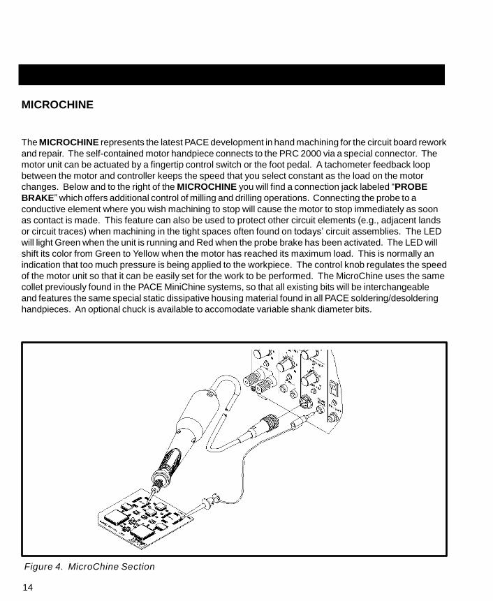
MICROCHINE
The MICROCHINE represents the latest PACE development in hand machining for the circuit board rework
and repair. The self-contained motor handpiece connects to the PRC 2000 via a special connector. The
motor unit can be actuated by a fingertip control switch or the foot pedal. A tachometer feedback loop
between the motor and controller keeps the speed that you select constant as the load on the motor
changes. Below and to the right of the MICROCHINE you will find a connection jack labeled “PROBE
BRAKE” which offers additional control of milling and drilling operations. Connecting the probe to a
conductive element where you wish machining to stop will cause the motor to stop immediately as soon
as contact is made. This feature can also be used to protect other circuit elements (e.g., adjacent lands
or circuit traces) when machining in the tight spaces often found on todays’ circuit assemblies. The LED
will light Green when the unit is running and Red when the probe brake has been activated. The LED will
shift its color from Green to Yellow when the motor has reached its maximum load. This is normally an
indication that too much pressure is being applied to the workpiece. The control knob regulates the speed
of the motor unit so that it can be easily set for the work to be performed. The MicroChine uses the same
collet previously found in the PACE MiniChine systems, so that all existing bits will be interchangeable
and features the same special static dissipative housing material found in all PACE soldering/desoldering
handpieces. An optional chuck is available to accomodate variable shank diameter bits.
Figure 4. MicroChine Section

15
PIK AND PASTE
Located in the middle of the front panel, you will find the PIK
AND PASTE section of the PRC 2000. The Pik-Vac feature
provides a quiet and gentle vacuum source to the Pik-Vac wand
for use in handling and placing your surface mount parts.
Turning on the PIK-VAC Power Switch will cause a continuous
vacuum to be made available to the pick. A variety of tip and
vacuum cups are supplied to handle most surface mount parts.
The Green LED will light to indicate when the PIK-VAC is
running. There is also a low pressure auxiliary PIK
PRESSURE Port located on the rear panel which can be used
to operate low pressure accessories such as a sprayer.
The paste dispensing system occupies the right half of the PIK
AND PASTE section of the PRC 2000 and can dispense a
variety of solder cremes, fluxes, potting compounds and
adhesives. The Paste Dispense air hose comes equipped to
accept standard 10cc material barrels. The self-contained
pump supplies nominal 40psi (.28 MPa) of air pressure to the
syringe. Above the PASTE DISP Port, you will find a 2-
position switch labeled TIMED and CONT (Continuous). In the
continuous (CONT) position the dispenser pump will supply
continuous air pressure to the syringe while the foot pedal
remains depressed (FOOT PEDAL Selector Switch in "PD"
position). In the "TIMED" position, the control knob above the
switch becomes active. Each depression of the foot pedal will
activate the pump from 0.1 to 10 seconds. The LED will light
Figure 5. Pik And Paste Section
Yellow to indicate when the pump is running and will shift to Green when air pressure is being applied to
the syringe.
NOTE
Whenever the FOOT PEDAL Selector Switch is in the “PD” position, the
pump will periodically run for short periods to maintain internal pressure. The
pump will continue to run (Yellow LED lit) while the system recharges.
NOTE
As with any dispensing system, when thick viscous material or solder paste
is to be dispensed, ensure that the material is fresh, has been stored
properly and is at room temperature as per supplier's recommendations.
16
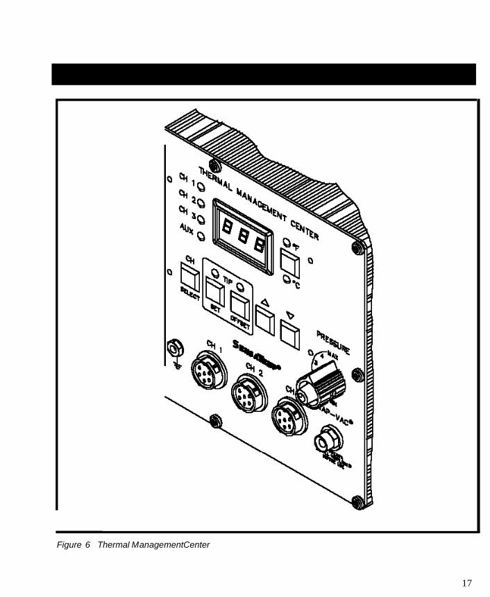
THERMAL MANAGEMENT CENTER
The THERMAL MANAGEMENT CENTER occupying the right 1/3 of the front panel is the heart of your
PRC 2000 system. This microprocessor based multi-channel center can control up to six devices at one
time. To the left of the Digital Readout are the three LEDs which indicate the "Current Channel" (i.e., the
channel whose temperature information can be adjusted and is displayed on the Digital Readout (CH 1,
CH 2 and CH 3)). Below these is the Green AUX (Auxiliary) LED. When this LED is lit in conjunction
with one of the channel LEDs, the Digital Readout displays temperature information of the three auxiliary
channels located on the rear panel. To the right of the Digital Readout is the °F/°C Key which allows the
operator to switch instantly between a ° F and ° C display. Located just below the Digital Readout is an
array of five keys. In normal operation, these keys control channel selection, tip temperature and tip
temperature offset settings. The two keys with up and down arrows are used for scrolling the
temperature and offset settings up and down. The LEDs located above the SET and OFFSET Keys
normally indicate which function is being adjusted. In Calibration (CAL) Mode, these same keys are also
used for entering, setting and clearing the password features as well as adjusting temperature
parameters and system set-up. By entering the tip temperature offset and the tip temperature, the true
tip temperature will be displayed on the Digital Readout. All these features will be discussed in the
operation section of the manual. Below the keys are three receptacles for attaching any three low
voltage SensaTemp handpieces in any configuration up to 100 watts/channel (300 watts total) power.
There are three additional receptacles on the lower left section of the rear panel. These will accept up to
three additional, externally powered, devices which are temperature controlled by the THERMAL
MANAGEMENT CENTER. As an alternative, any of the rear panel receptacles can accept a foot pedal
which will control the internal vacuum/pressure pump in addition to using the finger-actuated switches
found on the SensaTemp handpieces. SensaTemp handpieces available for use with your PRC 2000
include:
SP-2A Sodr-Pen Soldering Iron, SP-
1A Sodr-Pen Soldering Iron, SX-70
Sodr-X-Tractor Handpiece, TT-65
ThermoTweez Handpiece, TP-65
ThermoPik Handpiece,
DTP-80 Dual ThermoPik Handpiece, TJ-
70 Mini ThermoJet Handpiece.
Just to the left of the three SENSATEMP receptacles is a grounding jack which will accept a standard
banana plug. This can be used for grounding the operation, the work or additional equipment. To the right
of the SENSATEMP receptacles you will find the SNAP-VAC Vacuum and Controllable PRESSURE Ports.
The SNAP-VAC Port (bottom) should always have a VisiFilter attached in order to protect the vacuum
pump from any ingested material and to help muffle noise when the motor is running. The Controllable
PRESSURE Port (top) is used to supply air to the Mini ThermoJet handpiece. The rate of delivered air flow
17
Figure 6 Thermal ManagementCenter
18
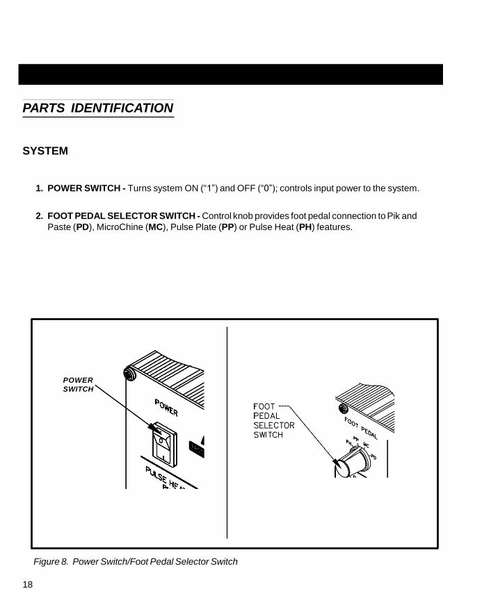
PARTS IDENTIFICATION
SYSTEM
1. POWER SWITCH - Turns system ON (“1”) and OFF (“0”); controls input power to the system.
2. FOOT PEDAL SELECTOR SWITCH - Control knob provides foot pedal connection to Pik and
Paste (PD), MicroChine (MC), Pulse Plate (PP) or Pulse Heat (PH) features.
POWER
SWITCH
Figure 8. Power Switch/Foot Pedal Selector Switch

19
FRONT PANEL FEATURES
PULSE HEAT
3. PULSE HEAT OUTPUTS - Low voltage AC power outputs for Low Voltage, Pulse Heat
handpieces.
4. PULSE HEAT OUTPUT CONTROL - Controls low voltage AC power at PULSE HEAT Outputs.
5. PULSE HEAT LED - Illuminates Green in color when power is applied (by foot pedal through
FOOT PEDAL Selector Switch) to the PULSE HEAT Outputs.
Figure 9. Pulse Heat Section

20
PULSE PLATE
6. PULSE PLATE OUTPUTS - DC power connections for PACE SwaPlater plating system.
7. PULSE PLATE OUTPUT CONTROL - Controls DC power at PULSE PLATE Outputs.
8. PULSE PLATE LED - Illuminates Green to indicate when power is applied (upon foot pedal
actuation) at the PULSE PLATE Outputs. Illuminates Red if an overcurrent condition occurs
during plating.
Figure 10. Pulse Plate Section

21
MICROCHINE
9. MICROCHINE POWER RECEPTACLE - Provides power, speed control, tip ground and finger
switch connection for the MicroChine handpiece.
10. VARIABLE SPEED CONTROL - Controls motor speed (2,500 - 10,000 RPMs) of MicroChine
handpiece.
11. PROBE BRAKE RECEPTACLE - Provides Probe Brake connection for the MicroChine Probe
Brake feature. See MicroChine portion of this manual for details.
12. STATUS LED - Illuminates Green to indicate MicroChine operation. Illuminates Amber if
maximum torque load is reached. Illuminates Red to indicate braking status when Probe Brake
circuit is activated.
Figure 11. MicroChine Section
22
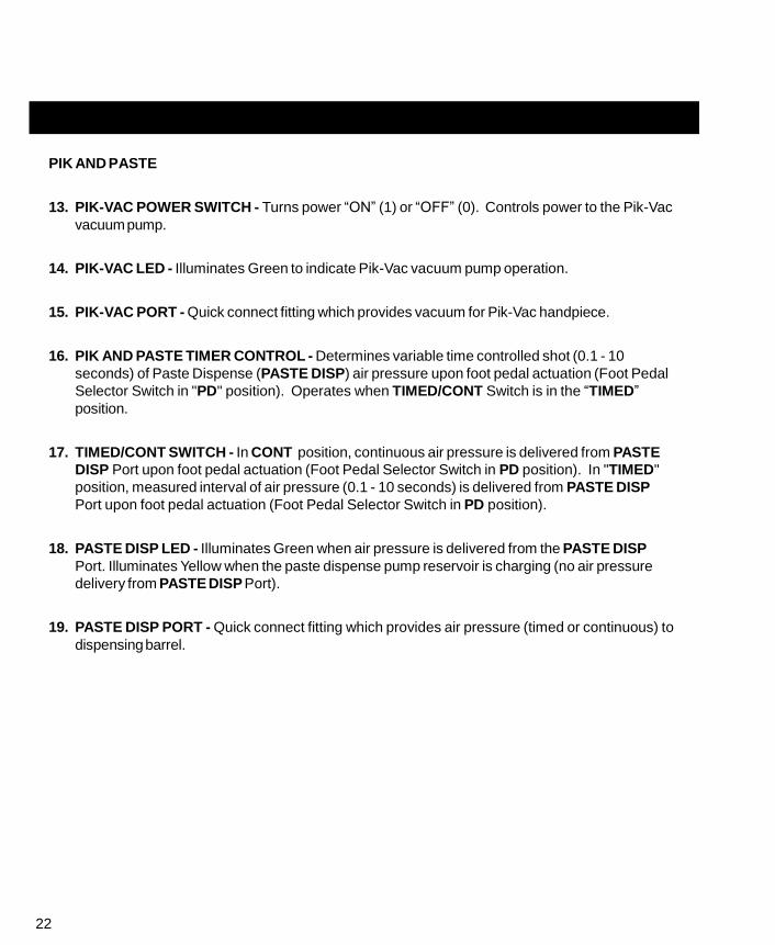
PIK AND PASTE
13. PIK-VAC POWER SWITCH - Turns power “ON” (1) or “OFF” (0). Controls power to the Pik-Vac
vacuum pump.
14. PIK-VAC LED - Illuminates Green to indicate Pik-Vac vacuum pump operation.
15. PIK-VAC PORT - Quick connect fitting which provides vacuum for Pik-Vac handpiece.
16. PIK AND PASTE TIMER CONTROL - Determines variable time controlled shot (0.1 - 10
seconds) of Paste Dispense (PASTE DISP) air pressure upon foot pedal actuation (Foot Pedal
Selector Switch in "PD" position). Operates when TIMED/CONT Switch is in the “TIMED”
position.
17. TIMED/CONT SWITCH - In CONT position, continuous air pressure is delivered from PASTE
DISP Port upon foot pedal actuation (Foot Pedal Selector Switch in PD position). In "TIMED"
position, measured interval of air pressure (0.1 - 10 seconds) is delivered from PASTE DISP
Port upon foot pedal actuation (Foot Pedal Selector Switch in PD position).
18. PASTE DISP LED - Illuminates Green when air pressure is delivered from the PASTE DISP
Port. Illuminates Yellow when the paste dispense pump reservoir is charging (no air pressure
delivery from PASTE DISP Port).
19. PASTE DISP PORT - Quick connect fitting which provides air pressure (timed or continuous) to
dispensing barrel.

23
Figure 12. Pik And Paste Section

24
THERMAL MANAGEMENT CENTER
Refer to the illustration following for location of parts.
20. CH 1 POWER RECEPTACLE - Provides power, tip ground, sensing circuitry and finger switch
connection from PRC 2000 system to handpiece connected to Channel 1 (CH 1).
21. CH 2 POWER RECEPTACLE - Provides power, tip ground, sensing circuitry and finger switch
connection from PRC 2000 system to handpiece connected to Channel 2 (CH 2).
22. CH 3 POWER RECEPTACLE - Provides power, tip ground, sensing circuitry and finger switch
connection from PRC 2000 system to handpiece connected to Channel 3 (CH 3).
23. SNAP-VAC PORT - Quick connect fitting which provides quick-rise vacuum for Sodr-X-Tractor or
ThermoPik handpieces.
24. CONTROLLABLE PRESSURE PORT - Quick connect fitting with adjustable valve which
provides variable air flow for Mini ThermoJet handpiece and Sodr-X-Tractor handpiece (in Hot Jet
Mode).
25. DIGITAL READOUT - Provides a three digit display of the Current Channel (channel with
illuminated LED; CH 1, CH 2, CH 3 or AUX 1, AUX 2, AUX 3) temperature information. This
includes: Operating Tip Temperature in Temperature Display Mode (normal operation), Tip
Temperature Offset Constant in TIP OFFSET Mode, Set Tip Temperature in TIP SET Mode, and
other information in Calibration (CAL) Mode.
26. °F/°C KEY - Selects °F or °C display of Set and Operating Temperatures and Tip Temperature
Offset Constants.
27. °F LED - Illuminates when Set and Operating Tip Temperatures and Tip Temperature Offset
Constants are displayed in °F.
28. °C LED - Illuminates when Set and Operating Tip Temperatures and Tip Temperature Offset
Constants are displayed in °C.
29. CH 1 LED - Illuminates when Channel 1 (CH 1) or Auxiliary Channel (AUX 1) is the Current
Channel (i.e., the channel (with connected handpiece/tip or auxiliary accessory) whose
temperature information is displayed on the Digital Readout).

25
30. CH 2 LED - Illuminates when Channel 2 (CH 2) or Auxiliary Channel (AUX 2) is the Current
Channel (i.e., the channel (with connected handpiece/tip or auxiliary accessory) whose
temperature information is displayed on the Digital Readout).
31. CH 3 LED - Illuminates when Channel 3 (CH 3) or Auxiliary Channel (AUX 3) is the Current
Channel (i.e., the channel (with connected handpiece/tip or auxiliary accessory) whose
temperature information is displayed on the Digital Readout).
32. AUX LED - Illuminates when an auxiliary channel (on system rear panel) is the Current Channel
(i.e., the channel (with connected handpiece/tip or auxiliary accessory) whose temperature
information is displayed on the Digital Readout). One of the CH 1, CH 2 or CH 3 LEDs will
illuminate simultaneously with the Auxiliary LED to indicate, respectively, which of the auxiliary
channels is active (AUX 1, AUX 2 or AUX 3).
33. CH SELECT KEY - Selects the Current Channel (among “Active Channels” (i.e., those with a
connected handpiece or auxiliary accessory)).
34. TIP SET KEY - Allows the operator to adjust the Set Tip Temperature for the handpiece/tip
combination or Set Temperature for the auxiliary accessory connected to the Current Channel.
Places the THERMAL MANAGEMENT CENTER in the TIP SET (Tip Temperature Set) Mode.
35. TIP SET LED - Flashes when TIP SET Key is pressed indicating that the THERMAL
MANAGEMENT CENTER is in TIP SET Mode.
36. TIP OFFSET KEY - Allows the operator to adjust the TIP OFFSET CONSTANT for the
handpiece or auxiliary accessory connected to the Current Channel. Places the THERMAL
MANAGEMENT CENTER in the TIP OFFSET (Tip Temperature Offset) Mode.
37. TIP OFFSET LED - Flashes when TIP OFFSET Key is pressed indicating that the THERMAL
MANAGEMENT CENTER is in the TIP OFFSET Mode. Remains illuminated (not flashing) in
Temperature Display Mode (normal operating mode) when a Tip Temperature Offset Constant of
greater than “3” for °C (“6” for °F) is entered.
38. SCROLL UP KEY - Increases the Set Tip Temperature (in TIP TEMPERATURE SET Mode) and
Tip Temperature Offset Constant (in TIP TEMPERATURE OFFSET Mode) in one, then ten
degree increments. Also used in “CAL” (Calibration) Mode.

26
39. SCROLL DOWN KEY - Decreases the Set Tip Temperature (in TIP SET Mode) and Tip
Temperature Offset Constant (in TIP OFFSET Mode) in one, then ten degree increments. Also
used in “CAL” (Calibration) Mode.
40. EARTH GROUND RECEPTACLE - Provides positive earth ground to which a ground cable can
be connected from the workpiece or work surface as part of a static control program.
Figure 13. Thermal Management Center Parts I.D.

27
REAR PANEL
41. AC POWER RECEPTACLE/FUSE HOLDER - Receptacle for providing power to the PRC 2000
system from AC outlet through power cord. Also location of fuse (F1) which protects the
system from overcurrent conditions.
42. FUSE F1 - Provides overload protection for PRC 2000 system.
43. FOOT PEDAL RECEPTACLE - Input for foot pedal which operates the Pik and Paste,
MicroChine, Pulse Plate or Pulse Heat features of the system as determined by the FOOT
PEDAL Selector Switch.
NOTE
The Auxiliary Power Receptacles listed below (items 44-46) will provide
temperature control for line operated auxiliary accessories or foot pedal
operation only. SensaTemp handpieces will not function properly if
connected to these outputs.
44. AUX 1 POWER RECEPTACLE - Provides temperature control, tip ground sensing circuitry and
finger switch connection from THERMAL MANAGEMENT CENTER to the auxiliary accessory
connected to Auxiliary Channel 1. Foot pedal attachment to this receptacle will allow vacuum/
pressure pump operation through foot pedal actuation.
45. AUX 2 POWER RECEPTACLE - Provides temperature control, tip ground sensing circuitry and
finger switch connection from THERMAL MANAGEMENT CENTER to the auxiliary accessory
connected to Auxiliary Channel 2. Foot pedal attachment to this receptacle will allow vacuum/
pressure pump operation through foot pedal actuation.
46. AUX 3 POWER RECEPTACLE - Provides temperature control, tip ground sensing circuitry and
finger switch connection from THERMAL MANAGEMENT CENTER to the auxiliary accessory
connected to Auxiliary Channel 3. Foot pedal attachment to this receptacle will allow vacuum/
pressure pump operation through foot pedal actuation.
47. FUSE F2 - Provides overload protection for CH 1, CH 2 and CH 3 power receptacles.
48. PIK PRESSURE PORT - Low pressure output with quick connect fitting. Controlled by PIK-
VAC Power Switch (front panel).

28
49. TIP & TEMPERATURE SELECTION SYSTEM CHART HOLDER (NOT SHOWN) - Holds
PACE’s Tip & Temperature Selection System charts (booklet) which enable the operator to
accurately set and display the true, correct operating tip temperature for any handpiece/tip
configuration connected to CH 1, CH 2 or CH 3.
Figure 14. Rear Panel Parts I.D.
29
The purpose of this "SAFETY" section is to inform users of the heading guidelines used in this manual to
indicate special Notes, Cautions, Warnings or Dangers. Also included are recommended precautions
which must be observed when operating or servicing this product.
HEADING GUIDELINES
PACE adheres to the following Heading Guidelines (based on OSHA guidelines) when listing special
information or precautions to be taken. Especially important are all procedures and practices which, if
not strictly observed, could result in injury or loss of life.
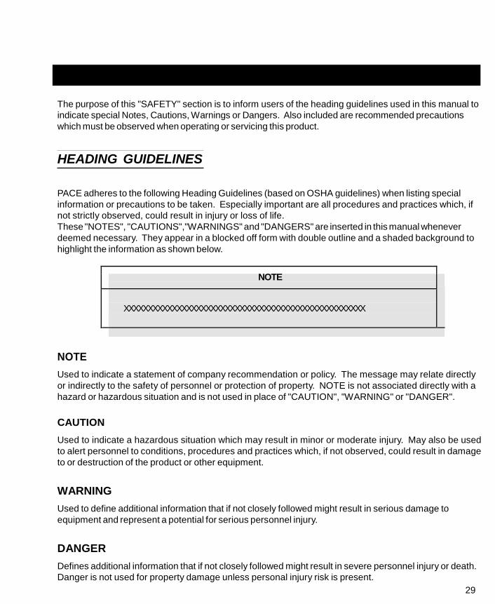
These "NOTES", "CAUTIONS","WARNINGS" and "DANGERS" are inserted in this manual whenever
deemed necessary. They appear in a blocked off form with double outline and a shaded background to
highlight the information as shown below.
NOTE
XXXXXXXXXXXXXXXXXXXXXXXXXXXXXXXXXXXXXXXXXXXXXXXXXX
NOTE
Used to indicate a statement of company recommendation or policy. The message may relate directly
or indirectly to the safety of personnel or protection of property. NOTE is not associated directly with a
hazard or hazardous situation and is not used in place of "CAUTION", "WARNING" or "DANGER".
CAUTION
Used to indicate a hazardous situation which may result in minor or moderate injury. May also be used
to alert personnel to conditions, procedures and practices which, if not observed, could result in damage
to or destruction of the product or other equipment.
WARNING
Used to define additional information that if not closely followed might result in serious damage to
equipment and represent a potential for serious personnel injury.
DANGER
Defines additional information that if not closely followed might result in severe personnel injury or death.
Danger is not used for property damage unless personal injury risk is present.

30
PRECAUTIONS
The following are general safety precautions which personnel must understand and follow when using or
servicing this product. These precautions may or may not be included elsewhere in this manual.
USEAGE PRECAUTIONS
CAUTIONS
1. SensaTemp handpiece heaters and installed tips are hot when handpiece is powered on. DO
NOT touch either the heater or tip. Severe burns may result! Always store handpiece in the
appropriate Tip & Tool Stand or cubby when not in use.
2. Always use this system in a well ventilated area. A fume extraction system such as those
available from PACE are highly recommended to protect personnel from solder flux fumes.
3. Exercise proper precautions when using chemicals (e.g., solder paste). Refer to the Material
Safety Data Sheet (MSDS) supplied with each chemical and adhere to all safety precautions
recommended by the manufacturer.
NOTES
1. The solder collection chamber in the PACE Sodr-X-Tractor is made of glass. Never remove
this chamber using pliers. Breakage of the chamber may result. Always remove using the
procedures recommended by PACE in the associated handpiece manual.
2. The front end (heater end) of the glass solder collection chamber in the PACE Sodr-X-Tractor is
hot when the handpiece is in use. When removing the chamber for cleaning, grip the chamber
at the rear seal. Never touch the front end of the glass chamber with bare hands. Allow the
chamber to cool before cleaning.
3. Always store any connected handpiece in the appropriate Tip & Tool Stand or cubby.
SERVICING PRECAUTIONS
DANGERS
POTENTIAL SHOCK HAZARD - Repair procedures performed on this product should be performed
by qualified service personnel only. Line voltage parts will be exposed when equipment is
disassembled. Service personnel must avoid contact with these parts when troubleshooting the
power source.
NOTES
Refer to the PRC 2000 Service Manual (P/N 5050-0344) whenever service is required.

31
To insure continued peak performance, use genuine PACE replacement parts.

30
CAUTION
To insure operator safety, the AC supply receptacle must be checked for
proper grounding before initial operation.
SYSTEM
Set up the PRC 2000 system using Figures 15 through 18 and the following steps.
1. Store the shipping container(s) in a convenient location. Reuse of these containers will prevent
damage if you ship or store the system.
2. Place POWER Switch in the “OFF” or “0” position.
3. Position the system on a convenient bench.
4. Insert the power cord into AC Power Receptacle at the rear
panel
of the system.
Figure 15. Power Off
5. Assemble and attach Tip & Tool Stands & Hot Cubbies to the
power source. Assembly instructions are enclosed with each
Tip & Tool Stand and Hot Cubby.
6. Using Figure 16 as a guide, install the Tip & Temperature
Selection System Chart Holder to the top of the power source.
7. Install the Tip & Temperature Selection System Chart booklet
onto the Chart Holder.
8. Place handpiece(s) into the Tip & Tool Stands and Hot Cubbies.
Figure 16. Chart Holder

31
SYSTEM CONT'D
9. Connect handpiece connector plug(s) to THERMAL
MANAGEMENT CENTER (TMC) Power
Receptacle(s) CH 1, CH 2 and/or CH 3 as follows.
a) With the Connector Key end facing the power
source, turn the Locking Ring fully
counterclockwise.
b) Align Connector Key with Receptacle Keyway of
Power Receptacle.
c) Insert connector into Power Receptacle.
d) Turn Locking Ring fully clockwise to lock in
place.
10. To avoid confusion among handpieces, PACE
recommends the use of colored markers (P/N 6993-
0136 Cable Marker Kit) to identify the particular
handpiece power cord and/or air hose. Attach any
two like colored markers, one to each end of the
handpiece power cord or air hose. Select and use a
different colored marker for each handpiece. Labels
are also provided to mark Tip & Tool Stands and Hot
Cubbies with the name of the associated handpiece.
Receptacle on rear panel of power source to enable
foot pedal operation of MICROCHINE (MC), PIK
AND PASTE (PD), PULSE HEAT (PH) and PULSE
PLATE (PP) features (as selected by position of
FOOT PEDAL Selector Switch).
12. Install additional handpieces and accessories as
necessary using the “Set-Up” instructions and the
manual supplied with each handpiece.
13. Plug the prong end of the power cord into a
convenient three wire grounded AC power outlet.
The system is now ready for operation.
14. Read the “OPERATION” section of this manual
Figure 17. TMC Handpiece Connection
Figure 18. Foot Pedal Connection

32 thoroughly before operating the system.

33
HANDPIECE VACUUM/PRESSURE
The SX-65A, SX-70 and TP-65 handpieces require the use of the SNAP-VAC (vacuum) Port and the TJ-70
handpiece requires the use of the Controllable PRESSURE Port on the THERMAL MANAGEMENT
CENTER (TMC).
There are two preferred methods for connection of the Air Hose. The advantages of each method are
discussed in the paragraph below. Select the method best suited to your particular application.
1. TRADITIONAL METHOD - Best suited for single air handpiece configurations. Configuration
allows the air hose to be attached to the handpiece power cord. Any TJ-70 Mini ThermoJet
handpiece should be configured using this method.
2. QUICK CONNECT METHOD - Best suited for THERMAL MANAGEMENT CENTER
configurations which include multiple air handpiece attachment. A single Air Hose can be
easily transferred between handpieces using quick connect fittings attached to the rear of each
handpiece.
PROCEDURES:
TRADITIONAL METHOD
1. Connect the 54 inch (137cm) length of Air Hose to the
metal tube in the back of the air handpiece.
2. Insert the ridged end of a male quick connect hose
mount Fitting (P/N 1259-0087) into the free end of the
54 inch (137cm) Air Hose.
3. Secure the Air Hose to the handpiece power cord with
cable clips (P/N 1321-0085-01).
Fitting
Air Hose
Figure 19. Air Hose To Fitting

Figure 21. Handpiece Connection to TMC
34
TRADITIONAL METHOD CONT'D
4. Prepare a VisiFilter in the following manner.
a) Connect a 1 inch (2.5cm) length of clear pvc Air
Hose to each side of the VisiFilter; push and turn
hose onto VisiFilter nipple to seat.
b) To the free end of the Air Hose connected to the
FLOW IN side of the VisiFilter, insert the ridged end
of a female quick connect hose mount Fitting (P/N
1259-0086).
c) Insert the ridged end of a male quick connect hose
mount Fitting (P/N 1259-0087) in the free end of the
Air Hose connected to the FLOW OUT side of the VisiFFiltiegr.ure 20. VisiFilter Preparation
d) Connect VisiFilter Air Hose (with attached male quick
connect hose mount Fitting) to the power source SNAP-VAC Port.
5. For vacuum, insert male quick connect hose mount Fitting connected to long Air Hose into
female Fitting on 1 inch (2.5cm) Air Hose (connected to VisiFilter). For pressure, insert male
quick connect hose mount fitting directly into the Controllable PRESSURE Port.
CAUTION
When removing any Air Hose, turn and pull. DO NOT attempt to pull hose
directly off. Damage to or breakage of Vacuum Fitting or VisiFilter may
occur.
6. Connect the handpiece power cord connector
plug to one of the Power Receptacles. For
convenience, PACE recommends the use of CH 3
for air handpieces.

35
NOTE
If more than one air-operated handpiece is connected to the THERMAL
MANAGEMENT CENTER, insure that only one of the Air Hoses is
connected to either the SNAP-VAC Port or Controllable PRESSURE Port.
Attachment to both simultaneously will cause a deterioration in perfor-
mance.
QUICK CONNECT METHOD
May be used with any SensaTemp handpiece except TJ-70 Mini ThermoJet.
1. Prepare a VisiFilter in the following manner.
a) Connect a 1 inch (2.5cm) length of clear pvc Air
Hose to each side of the VisiFilter; push and turn
hose onto VisiFilter nipple to seat.
b) To the free end of the Air Hose connected to the
FLOW IN side of the VisiFilter, insert the ridged end
of a female quick connect hose mount Fitting (P/N
1259-0086).
c) Insert the ridged end of a male quick connect hose
mount Fitting (P/N 1259-0087) in the free end of the
Air Hose connected to the FLOW OUT side of the
VisiFilter.
2. Insert male quick connect hose mount Fitting
(attached to VisiFilter assembly) into female SNAP-
VAC Port on front panel of power source.
Figure 22. VisiFilter Preparation

36
When removing any Air Hose, turn and pull. DO NOT attempt to pull hose
directly off. Damage to or breakage of vacuum fitting or VisiFilter may occur.
QUICK CONNECT METHOD CONT'D
3. Attach the ridged end of a male quick connect hose
mount Fitting (P/N 1259-0087) to each end of the 54
inch (137cm) Air Hose. Push and turn hose onto each
Fitting to seat properly. You may install metal hose
clamps (enclosed with system) to further secure
connections.
4. For each air handpiece, attach ridged end of a female
quick connect hose mount Fitting to a 1 inch (2.5cm)
length of clear pvc Air Hose; push and turn hoses onto
Fittings to seat properly. You may install a metal hose
clamp (enclosed with system) to further secure the
connection.
AIR
HOSE
FITTING
5. Attach the opposite end of the 1 inch (2.5cm) length of
Figure 23. Air Hose To Handpiece
clear pvc Air Hose to the metal tube located at the rear of each handpiece.
6. Connect one end of the long Air Hose (with attached male quick connect hose mount Fitting) to
the 1" (2.5cm) clear pvc Air Hose attached to the rear of the handpiece.
7. For vacuum, insert male quick connect hose mount Fitting attached to the remaining end of the
long Air Hose into female quick connect hose mount Fitting on 1 inch (2.5cm) clear pvc Air
Hose (connected to VisiFilter). For pressure, insert male quick connect hose mount fitting
directly into the Controllable PRESSURE Port.
8. The long Air Hose may now be easily transferred between air handpieces by removal of male
quick connect hose mount Fitting (attached to long Air Hose) from female quick connect hose
mount Fitting at rear of air handpiece and attachment to another air handpiece.
CAUTION
9. Connect the handpiece power cable plugs of each air handpiece to the Power Receptacles.

INTRODUCTION
The PRC 2000 systems are easy to operate and allow the operator the flexibility of using additional
features as desired. The “Operation” portion of this manual will familiarize the user with the features of the
system as received from the factory.
DEFINITIONS
Please read and become familiar with each of the following definitions. Each term is used repeatedly in
the following operational procedures to avoid any possible confusion as to the intent of any particular
instruction.
ACTIVE CHANNEL - Any channel with a connected handpiece.
AUTOMATIC POWER DOWN - Feature which turns off power to all three channels 90 minutes after all
Active Channels have entered the Automatic Setback Mode.
AUTOMATIC TEMPERATURE SETBACK - System feature which, when enabled, will independently set
back each channel’s SET TIP Temperature to 180°C (350°F) after a user selected period of handpiece
inactivity (10 to 90 minutes settable in 10 minute increments). This feature is enabled in the “CAL” Mode.
CALIBRATION (CAL) MODE - Mode of operation (indicated by “CAL” on the Digital Readout) in which the
operator can quickly and easily recalibrate the system to insure accuracy and peak performance.
CURRENT CHANNEL - The channel whose temperature information may be set and displayed on the
Digital Readout. The Current Channel is indicated by an illuminated LED next to its designation. The
Auxiliary LED is illuminated in conjunction with the appropriate channel LED if an Auxiliary Channel is the
Current Channel.
INACTIVE CHANNEL - Any channel without a connected handpiece.
SET TIP TEMPERATURE - Operator selected idle tip temperature entered into the system memory in Tip
Set Mode for handpiece/tip combination connected to Current Channel.
TEMPERATURE DISPLAY MODE - Normal Operating Mode in which the true operating tip temperature of
the handpiece/tip connected to the Current Channel is displayed on the Digital Readout.
TIP OFFSET CONSTANT - Specific value for a given handpiece/tip combination upon which the system
automatically calculates the correct Tip Temperature Offset at the entered Set Tip Temperature.
TIP TEMPERATURE OFFSET - Temperature value difference between the point in the handpiece heater
assembly at which temperature is sensed and the working end of the attached tip.
TIP OFFSET MODE - Mode of operation in which the Current Channel’s TIP OFFSET CONSTANT value
can be viewed or altered. In this mode, the TIP OFFSET LED flashes and the stored value appears on the
Digital Readout.
TIP SET MODE - Mode of operation in which the Current Channel’s Set Tip Temperature can be viewed or
altered. In this mode, the TIP SET LED flashes and the stored value appears on the Digital Readout.
OPERATING TIP TEMPERATURE - The true tip temperature at which the handpiece tip operates at any (normal
given time. This temperature is displayed on the Digital Readout in Temperature Display Mode 37

38
THERMAL MANAGEMENT CENTER
POWER UP
1. Insure that the system is properly prepared for
operation. Refer to the “Set-Up” portion of this manual.
The handpieces selected for your application should be
connected to the unit. Connect any single air hose to
either the SNAP-VAC Port or Controllable PRESSURE
Port. Never connect air hoses to both ports
simultaneously. Always leave VisiFilter connected to
SNAP-VAC Port.
2. Turn the POWER Switch ON (“1”).
Figure 24. Power On
3. On power up, the Digital Readout will display "888"
initially; change to "1 - 3" (this number may be different
on your system) and then display normal temperature
information (Temperature Display Mode).
Figure 25. Digital Readout "888"

OPERATION
CHANNEL LED OPERATION
4. The Channel LED (CH 1, CH 2 or CH 3) of the first
Active Channel encountered by the system (Channel
with connected handpiece) will be illuminated. This is
the Current Channel. The Auxiliary LED (in conjunction
with the appropriate Channel led (CH 1, CH 2 or CH 3)
will illuminate if a Current Channel is an Auxiliary
Channel (AUX 1, AUX 2 or AUX 3). If no Channels are
active (no handpiece connected), only the CH 1 LED
will be illuminated and "E - 1" will be displayed on the
Digital Readout.
Figure 26. Channel LEDs
5. Disconnect the handpiece from the Power Receptacle
associated with the Current Channel (e.g., If CH 1 LED
is illuminated, disconnect the handpiece connected to
CH 1). The unit will now select the next Active Channel
encountered as the Current Channel and illuminate the
corresponding LED.
6. Reconnect the handpiece removed in step #5.
Figure 27. Handpiece Connection, TMC
39

40
DIGITAL READOUT OPERATION
7. The Digital Readout provides a 3 digit display of the
Current Channel temperature information. The Digital
Readout will show the Set Tip Temperature in the TIP
SET Mode, Tip Offset Constants in TIP OFFSET
Mode and the True (Operating Tip) Temperature in the
Temperature Display Mode (normal operation).
PANEL CONTROLS
8. With three handpieces connected to the system (no
auxiliary accessories connected), press the CH
SELECT Key several times to observe the lighting of
the CH 1, CH 2 & CH 3 LEDS. Each subsequent
pressing will turn an LED off and turn the next Active
Channels’ LED on. The illumination sequence will be
CH 1 to CH 2 to CH 3 and then back to CH 1.
Unplug any one of the handpieces and repeat. The
LED of any Inactive Channel (no attached handpiece)
will not light. The next Active Channel in sequence
will light. NOTE: CH 1 LED will illuminate and “E-1”
will be displayed on the Digital Readout if there are
no Active Channels. If all channels were set to
“OFF”, the Digital Readout will display “OFF”.
9. Press the TIP OFFSET Key. The TIP OFFSET LED
will blink and the Digital Readout will display the TIP
OFFSET CONSTANT for the Current Channel. As
received from the factory, the Digital Readout will
display “3” FOR °C (“6” FOR °F). If the TIP OFFSET
Key is immediately pressed again, or if no other
operation occurs within 5 seconds, the LED will turn
off and the Digital Readout will revert to the
Temperature Display Mode (normal operation).
Figure 28. Digital Readout "888"
Figure 29. TMC Front Panel
Figure 30. Tip Offset Key Activation

NOTE
If the Digital Readout displays "P - -", a pass-
word has been previously installed. Enter the
password at this point to continue. Refer to the
"Password" portion of this manual for details on
password operation.
NOTE
Refer to “Tip & Temperature Selection” for a complete discussion of Tip
Temperature Offset function.
10. Press the TIP OFFSET Key once to enter TIP
OFFSET Mode. Immediately press and hold the
Scroll Up Key. Observe the displayed TIP OFFSET
CONSTANT increase, first in 1° and then in 10°
increments. Release the Scroll Up Key when the
Digital Readout reads “33” for °C (“60” for °F).
Figure 31. Increase Tip Offset Value
11. While still in the TIP OFFSET Mode (TIP OFFSET
LED flashing) press and hold the Scroll Down Key.
Observe the displayed TIP OFFSET CONSTANT
decrease first in 1° and then in 10° increments.
Release the key when the Digital Readout displays
“28” for °C (“50” for °F).
Figure 32. Decrease Tip Offset Value
12. Immediately press the TIP OFFSET Key to exit the
TIP OFFSET Mode and enter the new TIP OFFSET
CONSTANT for the Current Channel into the system
memory. Notice that the TIP OFFSET LED remains
illuminated (not flashing). ONLY IF A CURRENT
CHANNEL HAS A TIP OFFSET CONSTANT
GREATER THAN THE DEFAULT (“3” for °C or “6” for
°F) DOES THIS LED REMAIN ILLUMINATED. The
system will retain stored Set Tip Temperatures and
TIP OFFSET CONSTANTS even when power is
removed.
Figure 33. Store Tip Offset Value
41

42
PANEL CONTROLS CONT'D
13. Press the TIP SET Key once. This is TIP SET
Mode. The TIP SET LED will flash and the Digital
Readout will display the stored Set Tip Temperature
for the Current Channel. As received from the
factory, the Digital Readout will display “OFF”. Also,
if no other operation occurs within 6 seconds, the
LED will turn off and the Digital Readout will revert to
the Temperature Display Mode. Pressing the TIP
SET Key a second time will immediately place the
system in the Temperature Display Mode (normal
operation).
14. Plug an auxiliary accessory (if purchased) into
any of the three Aux Power Receptacles (AUX 1,
2 or 3). Repeat step #8.
Figure 34. Display Stored Tip Temp.
Figure 35. Aux. Accessory Connection
Notice that each subsequent pressing of the CH
SELECT Key will illuminate the AUX LED and the
Channel LED corresponding to the auxiliary
channel to which the auxiliary accessory is
connected. The sequence in this case would be
CH 1 to CH 2 to CH 3 to CH 1 (plus the Auxiliary
LED) to indicate the active Auxiliary Channel
(AUX 1) and then back to CH 1.
Figure 36. Changing Current Channel

43
15. Press the TIP SET Key once again to enter the TIP
SET Mode. Press and hold the Scroll Up Key.
Observe as the displayed Set Tip Temperature
increases first in 1°, then in 10° increments (°C or °F).
Release the key when the Digital Readout reads 371°C
(or 700°F). Immediately press the TIP SET Key once
again. Observe the Digital Readout as the Operating
Tip Temperature reaches 371°C (or 700°F).
16. Press the °F/°C Key several times to observe the
alternating illumination of the °F & °C LEDS. Each
subsequent pressing of the key will turn one LED on
and the other off. Also notice as the Digital Readout
changes to display the Operating Tip Temperature in °F
when the °F LED is illuminated and in °C when the °C
LED is illuminated.
Figure 37. Enter Tip Temp. Set Mode
Figure 38. °F To °C Digital Readout
17. Press the TIP SET Key once to enter the TIP
TEMPERATURE SET Mode. Immediately press & hold
the Scroll Down Key. Observe as the displayed TIP
SET Temperature decreases first in 1° and then in 10°
increments (°C or °F). Release the key when the Digital
Readout displays 343°C (650°F). Immediately press the TIP SET Key once again (or wait 6 seconds) and observe the Operating Tip Temperature
Figure 39. Decreasing Set Tip Temp. decrease to 343°C (650°F).

44
PANEL CONTROLS CONT'D
18. Press the TIP SET Key once again and use the
Scroll Up and Scroll Down Keys to enter your desired
Set Tip Temperature. Immediately press the TIP SET
Key to exit the TIP SET Mode. This enters the new
Set Tip Temperature for the Current Channel into
system memory.
NOTE
If a Password has been installed in the system,
press the °F/°C Key to reactivate Password pro-
tection.
19. Note the Current Channel displayed on the system.
Turn the POWER Switch to the OFF (“0”) position.
Turn the POWER Switch back to the ON (“1”)
position. Using the CH SELECT Key, select the
channel displayed in step #18. Notice that the TIP
OFFSET LED is illuminated to indicate that a TIP
OFFSET CONSTANT higher than the default ("3" for
°C or "6" for °F) has been stored in system memory.
20. Press the TIP OFFSET Key. Notice that the system
has retained the stored TIP OFFSET CONSTANT.
Press the key once again to exit TIP OFFSET Mode.
KBTIPSUD.EPS
Figure 40. Changing Set Tip Temperature
Figure 41. Power Off
Figure 42. Storing Tip Offset Value
45
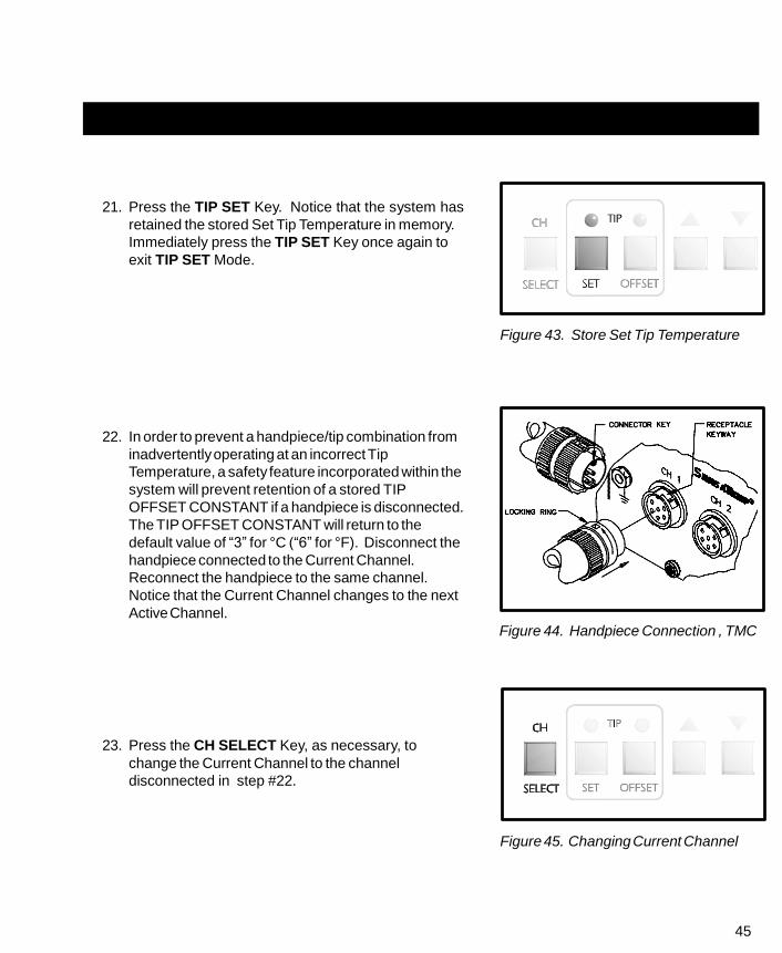
21. Press the TIP SET Key. Notice that the system has
retained the stored Set Tip Temperature in memory.
Immediately press the TIP SET Key once again to
exit TIP SET Mode.
Figure 43. Store Set Tip Temperature
22. In order to prevent a handpiece/tip combination from
inadvertently operating at an incorrect Tip
Temperature, a safety feature incorporated within the
system will prevent retention of a stored TIP
OFFSET CONSTANT if a handpiece is disconnected.
The TIP OFFSET CONSTANT will return to the
default value of “3” for °C (“6” for °F). Disconnect the
handpiece connected to the Current Channel.
Reconnect the handpiece to the same channel.
Notice that the Current Channel changes to the next
Active Channel.
23. Press the CH SELECT Key, as necessary, to
change the Current Channel to the channel
disconnected in step #22.
Figure 44. Handpiece Connection , TMC
Figure 45. Changing Current Channel

46
PANEL CONTROLS CONT'D
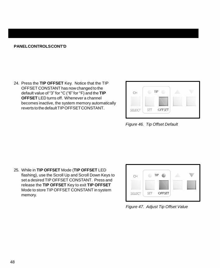
24. Press the TIP OFFSET Key. Notice that the TIP
OFFSET CONSTANT has now changed to the
default value of “3” for °C (“6” for °F) and the TIP
OFFSET LED turns off. Whenever a channel
becomes inactive, the system memory automatically
reverts to the default TIP OFFSET CONSTANT.
Figure 46. Tip Offset Default
25. While in TIP OFFSET Mode (TIP OFFSET LED
flashing), use the Scroll Up and Scroll Down Keys to
set a desired TIP OFFSET CONSTANT. Press and
release the TIP OFFSET Key to exit TIP OFFSET
Mode to store TIP OFFSET CONSTANT in system
memory.
Figure 47. Adjust Tip Offset Value

47
26. Using the CH SELECT Key, select each Active
Channel in sequence, making it the Current Channel
(temperature information displayed on Digital
Readout). Using the procedures described in
previous steps #10 thru 18 and steps #24 thru 25 as
a reference, enter and store desired SET TIP
Temperatures and appropriate TIP OFFSET
CONSTANTs into system memory. Refer to the “Tip
& Temperature Selection System” charts sent with
your unit and the “Tip & Temperature Selection”
portion of this manual for more detailed information
on selection of the proper Tip, Handpiece and
Temperature Options for your particular application.
Figure 48. Change Current Channel
NOTE
The PRC 2000 systems incorporate a “Dynamic Offset” feature which
automatically adjusts the Tip Temperature Offset (based on the entered TIP
OFFSET CONSTANT) for any Set Tip Temperature established by the
operator. This ensures the maintenance of true, accurate Tip Temperatures.
Simply stated, any operating Tip Temperature displayed on the Digital
Readout will be correct.
Always set the appropriate TIP OFFSET CONSTANT for the selected
Handpiece/Tip combination (listed in the shaded area on the Tip &
Temperature Selection System Charts) before entering the desired Set Tip
Temperature. The Set Tip Temperature + the Dynamically Adjusted Tip
Temperature Offset value (usually different from the entered Tip Offset
Constant) cannot exceed 489°C (912°F). If this limit is exceeded, the
system will automatically lower the maximum possible Set (and Operating)
Tip Temperature accordingly.
48
PANEL CONTROLS CONT'D
24. Press the TIP OFFSET Key. Notice that the TIP
OFFSET CONSTANT has now changed to the
default value of “3” for °C (“6” for °F) and the TIP
OFFSET LED turns off. Whenever a channel
becomes inactive, the system memory automatically
reverts to the default TIP OFFSET CONSTANT.
Figure 46. Tip Offset Default
25. While in TIP OFFSET Mode (TIP OFFSET LED
flashing), use the Scroll Up and Scroll Down Keys to
set a desired TIP OFFSET CONSTANT. Press and
release the TIP OFFSET Key to exit TIP OFFSET
Mode to store TIP OFFSET CONSTANT in system
memory.
Figure 47. Adjust Tip Offset Value

49
26. Using the CH SELECT Key, select each Active
Channel in sequence, making it the Current Channel
(temperature information displayed on Digital
Readout). Using the procedures described in
previous steps #10 thru 18 and steps #24 thru 25 as
a reference, enter and store desired SET TIP
Temperatures and appropriate TIP OFFSET
CONSTANTs into system memory. Refer to the “Tip
& Temperature Selection System” charts sent with
your unit and the “Tip & Temperature Selection”
portion of this manual for more detailed information
on selection of the proper Tip, Handpiece and
Temperature Options for your particular application.
Figure 48. Change Current Channel
NOTE
The PRC 2000 systems incorporate a “Dynamic Offset” feature which
automatically adjusts the Tip Temperature Offset (based on the entered TIP
OFFSET CONSTANT) for any Set Tip Temperature established by the
operator. This ensures the maintenance of true, accurate Tip Temperatures.
Simply stated, any operating Tip Temperature displayed on the Digital
Readout will be correct.
Always set the appropriate TIP OFFSET CONSTANT for the selected
Handpiece/Tip combination (listed in the shaded area on the Tip &
Temperature Selection System Charts) before entering the desired Set Tip
Temperature. The Set Tip Temperature + the Dynamically Adjusted Tip
Temperature Offset value (usually different from the entered Tip Offset
Constant) cannot exceed 489°C (912°F). If this limit is exceeded, the
system will automatically lower the maximum possible Set (and Operating)
Tip Temperature accordingly.

50
TIP & TEMPERATURE SELECTION
With any heating system, actual tip temperatures can differ greatly from temperature control settings.
PACE’s unique “Tip & Temperature Selection System” allows you to select and maintain True Tip
Temperatures for any size and type of tip and handpiece using the appropriate TIP OFFSET CONSTANT.
Included with your system is a Chart Holder which holds Procedural Instructions, a Quick Reference
Guide, a Customer Log and Charts for each handpiece currently available from PACE. Follow the
procedure given in the chart marked “Introduction” when using the charts for any particular handpiece.
Listed below is the summarized procedure.
PROCEDURE
Select the appropriate Handpiece Chart for your application based on component type and/or procedure
(e.g., SMD removal, thru-hole soldering, etc.) and identify the correct tip. Install tip into handpiece and
follow the procedure below.
1. In Tip Temperature Offset (TIP OFFSET) Mode, enter the TIP OFFSET CONSTANT (# in
shaded area) corresponding to your selected tip for the channel powering the handpiece.
2. In Tip Temperature Set (TIP SET) Mode, set ANY desired Tip Temperature up to the
maximum. The tip will idle at this temperature.
NOTE
The Tip Offset Value is internally calculated and adjusted automatically
(based on the TIP OFFSET CONSTANT) so that a True Tip Temperature is
always displayed on the Digital Readout - even when the desired Set Tip
Temperature is changed.
51
PASSWORD
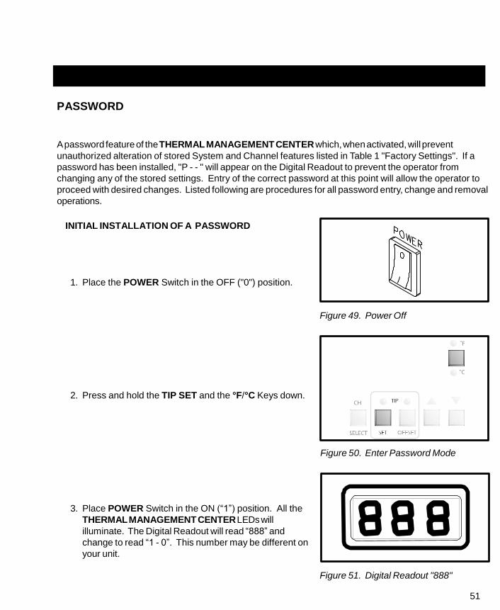
A password feature of the THERMAL MANAGEMENT CENTER which, when activated, will prevent
unauthorized alteration of stored System and Channel features listed in Table 1 "Factory Settings". If a
password has been installed, "P - - " will appear on the Digital Readout to prevent the operator from
changing any of the stored settings. Entry of the correct password at this point will allow the operator to
proceed with desired changes. Listed following are procedures for all password entry, change and removal
operations.
INITIAL INSTALLATION OF A PASSWORD
1. Place the POWER Switch in the OFF ("0") position.
Figure 49. Power Off
2. Press and hold the TIP SET and the °F/°C Keys down.
Figure 50. Enter Password Mode
3. Place POWER Switch in the ON (“1”) position. All the
THERMAL MANAGEMENT CENTER LEDs will
illuminate. The Digital Readout will read “888” and
change to read “1 - 0”. This number may be different on
your unit.
Figure 51. Digital Readout "888"

52
INITIAL INSTALLATION OF A PASSWORD CONT'D
4. Release the TIP SET and the °F/°C Keys. The system
is now in Password Mode. The Digital Readout will
display “PS-” and only the three Channel LEDs plus the
Auxiliary LED will remain illuminated signifying that the
system does not have a Password installed. NOTE: If
“P - -” is displayed on the Digital Readout instead of
“PS-”, a Password has been previously installed. Refer
to the “Removing/Changing Password” section
procedure.
Figure 52. Password Status
5. Write down the Password desired. Note that the TIP
SET Key may never be the first key of a Password (see
step #6).
Figure 53. First Key Not Tip Set Key

53
6. Press any key except the TIP SET Key as the first
key of the Password.
7. Press any key as the second key of the Password.
8. Press any key as the third (and last) key of the
Password.
The Calibration Mode has been automatically entered and the
Digital Readout will now display “CAL”. If no calibration
parameters need to be changed, exit Calibration Mode and go
to regular operation by pressing the TIP OFFSET Key.
Otherwise, perform calibration now (refer to the
CALIBRATION/SYSTEM SETUP section). When finished
doing calibration, press the TIP OFFSET Key to leave "CAL"
Mode and enter Temperature Display Mode (normal operation).
Figure 54. First Key Not Tip Set Key
Figure 55. Cal Mode
NOTE
The Password is not permanently stored until the Calibration Mode (“CAL”)
is exited normally by pressing the TIP OFFSET Key. If the POWER Switch
is turned OFF (“0”) while still in the Calibration Mode, the Password will not
be saved.

54
REMOVING A PASSWORD
1. Place the POWER Switch in the OFF (“0”) position.
Figure 56. Power Off
2. Press and hold the TIP SET and the °F/°C Keys
down.
Figure 57. Enter Password Mode
3. Place POWER Switch in the ON (“1”) position. All
the THERMAL MANAGEMENT CENTER LEDs will
illuminate. The Digital Readout will read “888” and
change to read “1 - 0”. This number may be different
on your unit.
Figure 58. Digital Readout "888"

55
4. Release the TIP SET and the °F/°C Keys. The Digital
Readout will now display “P - -” signifying that the
system is now asking for the operator to enter the
Password previously installed into the system's
memory.
Figure 59. Stored Password
NOTE
If “PS-” is displayed on the Digital Readout instead of “P - -”, a Password
has not been previously installed. Refer to the “INSTALLING A PASS-
WORD” section of this manual.
5. Press the first key of the Password.
6. Press the second key of the Password.
Figure 60. First Key Not Tip Set Key
56
REMOVING A PASSWORD CONT'D
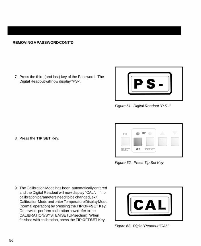
7. Press the third (and last) key of the Password. The
Digital Readout will now display “PS-”.
Figure 61. Digital Readout "P S -"
8. Press the TIP SET Key.
Figure 62. Press Tip Set Key
9. The Calibration Mode has been automatically entered
and the Digital Readout will now display “CAL”. If no
calibration parameters need to be changed, exit
Calibration Mode and enter Temperature Display Mode
(normal operation) by pressing the TIP OFFSET Key.
Otherwise, perform calibration now (refer to the
CALIBRATION/SYSTEM SETUP section). When
finished with calibration, press the TIP OFFSET Key.
Figure 63. Digital Readout "CAL"

57
NOTE
The password is not permanently removed until the Calibration Mode is
exited normally by pressing the TIP OFFSET Key. If AC POWER is turned
off while still in the Calibration Mode, the password will not be removed.
CHANGING THE PASSWORD
1. Place the POWER Switch in the OFF (“0”) position.
Figure 64. Power Off
2. Press and hold the TIP SET and the °F/°C Keys down.
Figure 65. Password Mode Entry

58
CHANGING THE PASSWORD CONT'D
3. Place Power Switch in the ON (“1”) position. All
the THERMAL MANAGEMENT CENTER LEDs will
illuminate. The Digital Readout will read “888” and
change to read “1-0”. This number may be different
on your unit.
Figure 66. Digital Readout "888"
4. Release the TIP SET and the °F/°C Keys. The
Digital Readout will now display “P - -” signifying that
the system has a Password installed. NOTE: If
“PS-” is displayed on the Digital Readout instead of
“P - -”, a Password has not been previously
installed. Refer to the “INSTALLING A PASSWORD”
procedure.
Figure 67. Digital Readout "P - -"
5. Write down the new Password desired. Remember
that the TIP SET Key may never be the first key of a
password.
Figure 68. First Key Not Tip Set Key

59
6. Press the first key of the old Password.
7. Press the second key of the old Password.
8. Press the third (and last) key of the old Password.
9. The Digital Readout will now display “PS-”.
Figure 69. Digital Readout "P S -"
10. Press any key, except the TIP SET Key, as the first
key of the new Password.
Figure 70. First Key Not Tip Set Key
CHANGING THE PASSWORD CONT'D
60
11. Press any key as the second key of the new
Password.
12. Press any key as the third (and last) key of the new
Password.
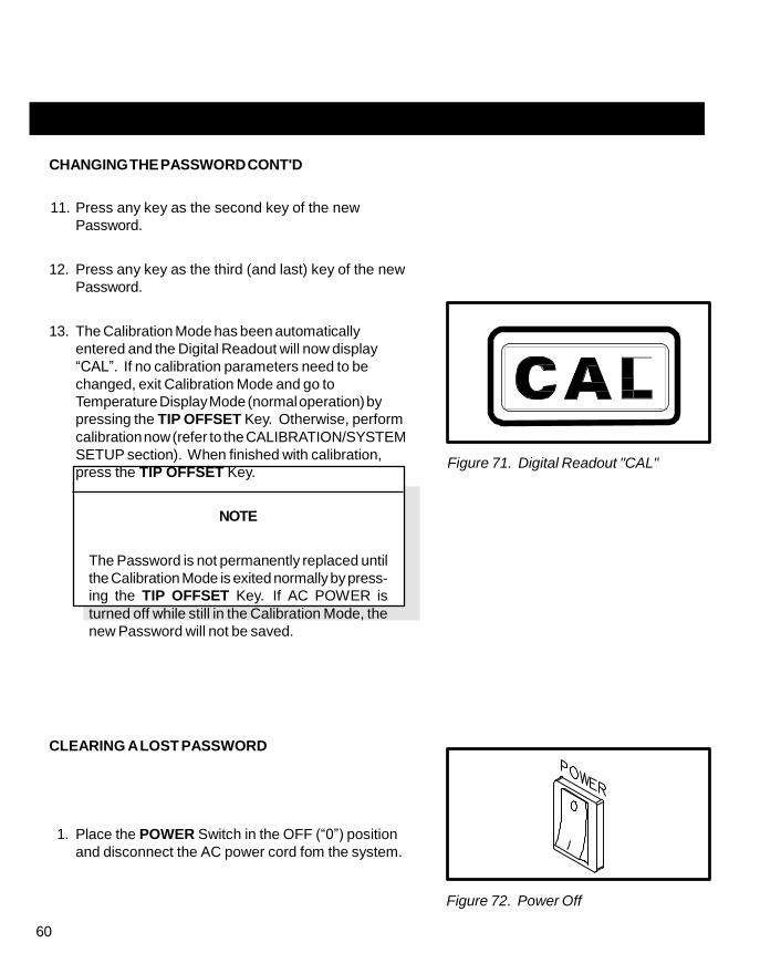
13. The Calibration Mode has been automatically
entered and the Digital Readout will now display
“CAL”. If no calibration parameters need to be
changed, exit Calibration Mode and go to
Temperature Display Mode (normal operation) by
pressing the TIP OFFSET Key. Otherwise, perform
calibration now (refer to the CALIBRATION/SYSTEM
SETUP section). When finished with calibration,
press the TIP OFFSET Key.
NOTE
The Password is not permanently replaced until
the Calibration Mode is exited normally by press-
ing the TIP OFFSET Key. If AC POWER is
turned off while still in the Calibration Mode, the
new Password will not be saved.
CLEARING A LOST PASSWORD
1. Place the POWER Switch in the OFF (“0”) position
and disconnect the AC power cord fom the system.
Figure 71. Digital Readout "CAL"
Figure 72. Power Off
61
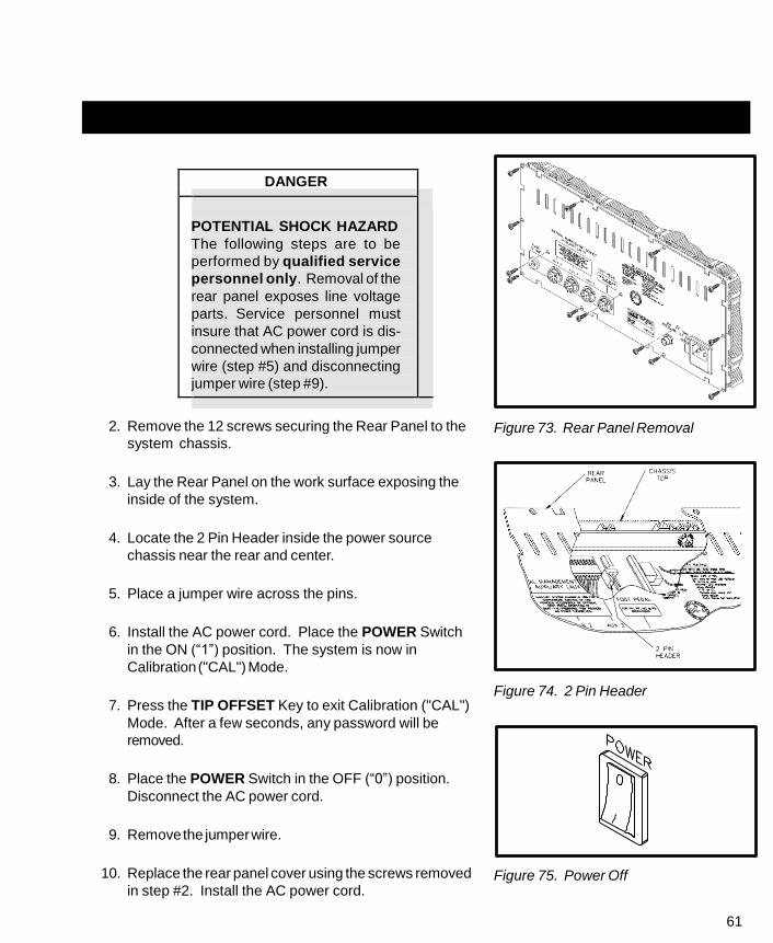
DANGER
POTENTIAL SHOCK HAZARD
The following steps are to be
performed by qualified service
personnel only. Removal of the
rear panel exposes line voltage
parts. Service personnel must
insure that AC power cord is dis-
connected when installing jumper
wire (step #5) and disconnecting
jumper wire (step #9).
2. Remove the 12 screws securing the Rear Panel to the
system chassis.
3. Lay the Rear Panel on the work surface exposing the
inside of the system.
4. Locate the 2 Pin Header inside the power source
chassis near the rear and center.
5. Place a jumper wire across the pins.
6. Install the AC power cord. Place the POWER Switch
in the ON (“1”) position. The system is now in
Calibration ("CAL") Mode.
7. Press the TIP OFFSET Key to exit Calibration ("CAL")
Mode. After a few seconds, any password will be
removed.
8. Place the POWER Switch in the OFF (“0”) position.
Disconnect the AC power cord.
9. Remove the jumper wire.
10. Replace the rear panel cover using the screws removed
in step #2. Install the AC power cord.
Figure 73. Rear Panel Removal
Figure 74. 2 Pin Header
Figure 75. Power Off

62
CALIBRATION
INTRODUCTION
In Calibration (CAL) Mode, you can:
1. Change the Upper & Lower Temperature limits for each channel independently.
2. Set the default temperature scale to °F or °C as desired.
3. Enable or disable the Auto Temperature Setback/Power Down features.
PROCEDURE
1. Place POWER Switch in the “Off” (“0”) position.
Figure 76. Power Off
2. Press and hold the TIP SET and Scroll Down Keys.
Figure 77. Calibration Entry

63
3. Place POWER Switch in the On (“1”) position. All of
the system LEDS will light. The Digital Readout will
read “888” and change to read “1-0”. This number may
be different on your unit.
Figure 78. Digital Readout "888"
4. Release the TIP SET and Scroll Down Keys. The
Digital Readout will now display “CAL” and only the
three Channel LEDs will remain lit signifying that the
system is now in Calibration (CAL) Mode. NOTE: If a
password has been installed, “P - -” will appear on the
Digital Readout. Enter the password key sequence to
display “CAL”.
Figure 79. Digital Readout "CAL"

64
°F/°C READOUT DEFAULT
5. Press and release the TIP SET Key. The Digital
Readout will display “S - X” (X = “-” or 1-9). Either the
°F or °C LED will be on. This is the default temperature
scale of the Digital Readout (e.g., if the °C LED is on,
the Digital Readout will display Tip Temperatures and
Tip Offset values in °C).
Figure 80. Digital Readout "S - X"
6. Press and release the °F/°C Key to change the default.
Each subsequent press and release of the key will
change the default.
Figure 81. Change Temperature Default
AUTOMATIC TEMPERATURE SETBACK
7. As received from the factory, “S - -” will be displayed
indicating that the Automatic Temperature Setback is
turned off. A “1” thru “9” appearing on the right side of
the Digital Readout indicates time to Automatic
Setback in increments of 10 minutes. For example, “S-
3” would indicate that any Active Channel will set back
its handpieces’ Set Tip Temperature to 180°C (350°F)
after 30 minutes of handpiece inactivity (non-use). To
change the time period or turn the Automatic
Temperature Setback feature off or on, use the Scroll
Keys. Press the Scroll Up Key to increase the time
period and/or enable the feature. Press the Scroll Down
Key to decrease the time period or disable the feature.
Figure 82. Adjust Setback Time
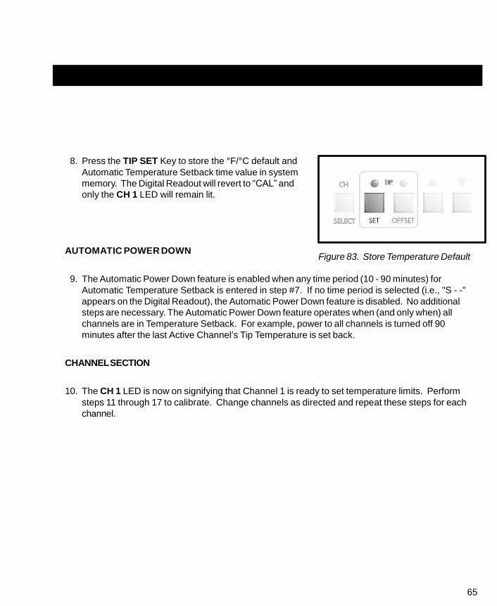
65
8. Press the TIP SET Key to store the °F/°C default and
Automatic Temperature Setback time value in system
memory. The Digital Readout will revert to “CAL” and
only the CH 1 LED will remain lit.
AUTOMATIC POWER DOWN
Figure 83. Store Temperature Default
9. The Automatic Power Down feature is enabled when any time period (10 - 90 minutes) for
Automatic Temperature Setback is entered in step #7. If no time period is selected (i.e., "S - -"
appears on the Digital Readout), the Automatic Power Down feature is disabled. No additional
steps are necessary. The Automatic Power Down feature operates when (and only when) all
channels are in Temperature Setback. For example, power to all channels is turned off 90
minutes after the last Active Channel’s Tip Temperature is set back.
CHANNEL SECTION
10. The CH 1 LED is now on signifying that Channel 1 is ready to set temperature limits. Perform
steps 11 through 17 to calibrate. Change channels as directed and repeat these steps for each
channel.
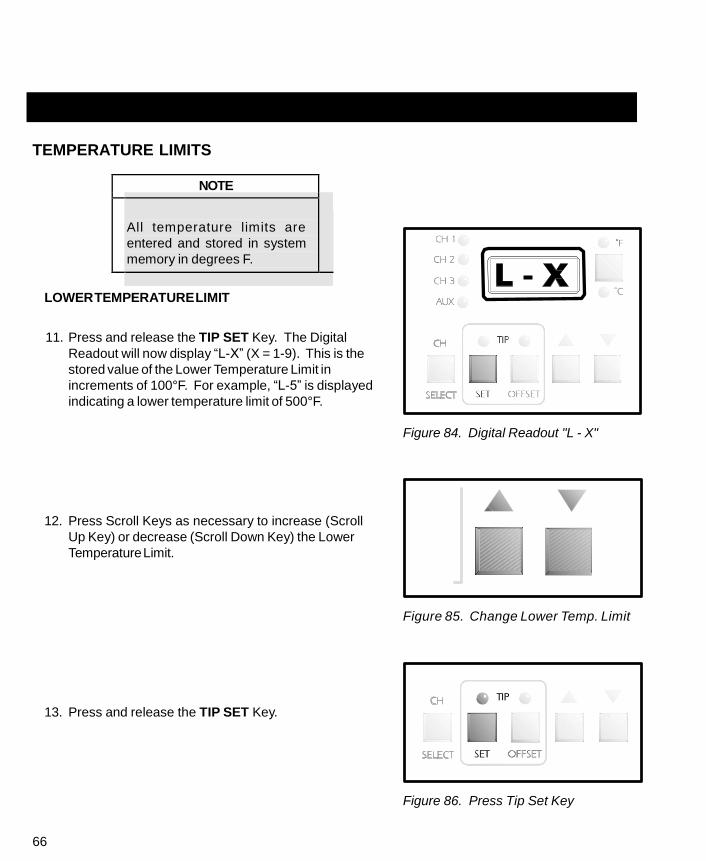
66
TEMPERATURE LIMITS
NOTE
All temperature limits are
entered and stored in system
memory in degrees F.
LOWER TEMPERATURE LIMIT
11. Press and release the TIP SET Key. The Digital
Readout will now display “L-X” (X = 1-9). This is the
stored value of the Lower Temperature Limit in
increments of 100°F. For example, “L-5” is displayed
indicating a lower temperature limit of 500°F.
Figure 84. Digital Readout "L - X"
12. Press Scroll Keys as necessary to increase (Scroll
Up Key) or decrease (Scroll Down Key) the Lower
Temperature Limit.
Figure 85. Change Lower Temp. Limit
13. Press and release the TIP SET Key.
Figure 86. Press Tip Set Key

67
UPPER TEMPERATURE LIMIT
14. The Digital Readout now displays “H-X” (X = 1-9).
This is the stored value of the upper temperature limit
in increments of 100°F.
Figure 87. Digital Readout "H - X"
15. Press Scroll Keys as necessary to increase (Scroll
Up Key) or decrease (Scroll Down Key) the upper
temperature limit.
Figure 88. Change Upper Temp. Limit
16. Press and release the TIP SET Key. The Digital
Readout will now display “CAL”. The next Active
Channel now becomes the Current Channel.
Perform steps 11 through 16 to set upper and lower
temperature limits for the other channels (CH 1, CH
2, CH 3, AUX 1, AUX 2 and AUX 3). After all
channels have been calibrated, you may exit the
Calibration (CAL) Mode by pressing and releasing
the TIP OFFSET Key.
Figure 89. Press Tip Set Key

68
UPPER TEMPERATURE LIMIT CONT'D
17. All values, features and defaults entered during the
calibration are now stored in memory and all Set Tip
Temperatures are turned “OFF”. All Channel TIP
OFFSET CONSTANTs are set to the default value of “3”
for °C (“6” for °F).
Figure 90. Digital Readout "OFF"
TEMPERATURE SETBACK
The PRC 2000 system is equipped with a Temperature Setback feature which, when enabled, will preserve
tip life and reduce energy consumption.
ACTIVATION
There are two ways in which the system will enable the Temperature Setback feature.
1. AUTOMATIC OPERATION - The system memory can be programmed so that each Active
Channel will automatically and independently set back its Set Tip Temperature to 180°C (350°F)
after a selected period (10-90 minutes) of handpiece inactivity. See “Calibration” section for
details on programming this feature.
2. MANUAL OPERATION - The operator can manually force the system to place all Active
Channels in Temperature Setback by performing the following procedure.
a) Press and hold the Scroll Down Key.
Figure 91. Forcing Temp. Setback

69
b) Press the Scroll Up Key.
c) Release both keys.
OPERATION
Figure 92. Temp. Setback Entry
1. Temperature Setback for each channel is indicated by the following.
a) The Current Channel LED will flash off once each 2 second period when that channel is in
Temperature Setback Mode.
b) Any Active, non-Current Channel LED will flash on once each 2 second period when that
channel is in Automatic Temperature Setback Mode.
2. Any Inactive Channel will not enter Temperature Setback Mode.
3. Any Active Channel whose Set Tip Temperature is less than 180°C (350°F) will enter
Temperature Setback Mode but will remain at its original Set Tip Temperature.
EXITING AUTOMATIC TEMPERATURE SETBACK MODE

70
Listed below are 4 different ways to exit Temperature Setback
Mode.
1. For any individual channel, perform the following
operation.
a) Press and release the CH SELECT Key until the
Setback Channel becomes the Current Channel
shown on the Digital Readout.
Figure 93. Changing Channel
b) Press and release the Scroll Up Key.
c) The system will now restore the previous Set Tip
Temperature of the Current Channel.
d) Observe the Digital Readout as the Operating Tip
Temperature increases to the Set Tip Temperature
(if above 180°C (350°F)). For optimum
performance, DO NOT attempt to use the attached
handpiece until Set Temperature is achieved.
2. For any individual channel, the attached handpiece
may be disconnected and reconnected. The
previously stored Set Tip Temperature will be restored
as in method #1 but the Tip Temperature Offset value
Figure 94. Restore Previous Tip Temp.
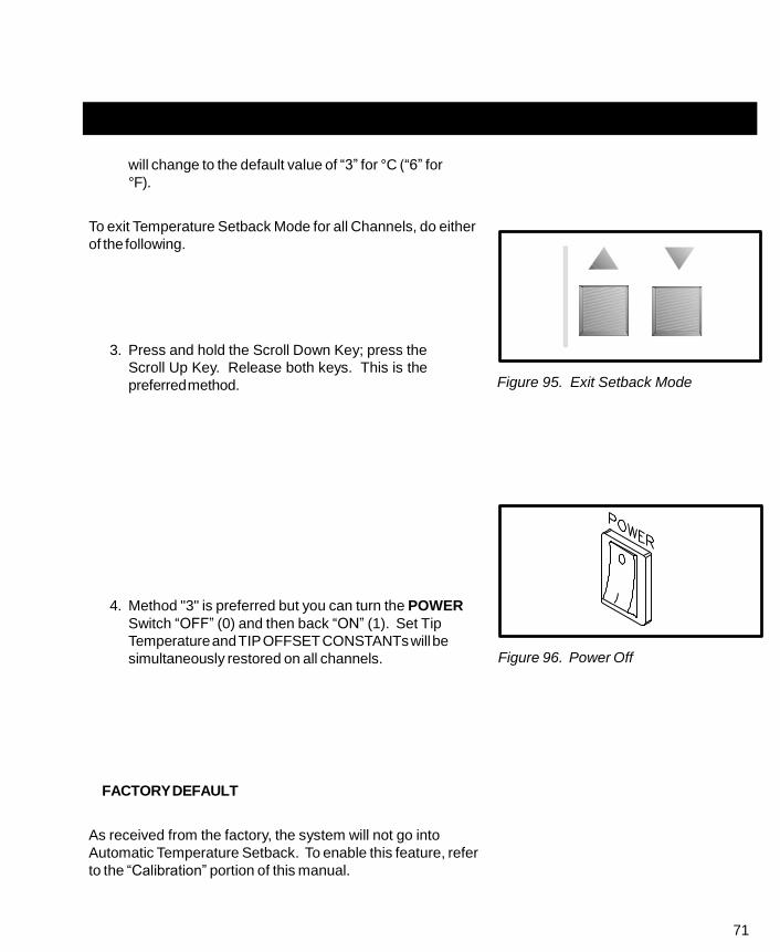
71
will change to the default value of “3” for °C (“6” for
°F).
To exit Temperature Setback Mode for all Channels, do either
of the following.
3. Press and hold the Scroll Down Key; press the
Scroll Up Key. Release both keys. This is the
preferred method.
4. Method "3" is preferred but you can turn the POWER
Switch “OFF” (0) and then back “ON” (1). Set Tip
Temperature and TIP OFFSET CONSTANTs will be
simultaneously restored on all channels.
FACTORY DEFAULT
As received from the factory, the system will not go into
Automatic Temperature Setback. To enable this feature, refer
to the “Calibration” portion of this manual.
Figure 95. Exit Setback Mode
Figure 96. Power Off

72
AUTOMATIC POWER DOWN
The Automatic Power Down feature of the PRC 2000 system is a safety feature which removes power from
all channels 90 minutes after all Active Channels have entered the Temperature Setback Mode. This
feature is not programmable and is automatically enabled when all Active Channels are in the Temperature
Setback Mode.
OPERATION
When all Active Channels have entered Automatic Temperature Setback Mode, a 90 minute timer within
the system circuitry will start running.
1. If the system has no Active Channels (no connected handpieces), Automatic Shutdown will not
occur.
2. If any key is pressed during the 90 minute time period, the timer is reset. Timer will not start
timing out again until all Active Channels are in Temperature Setback Mode.
3. During the last minute before the 90 minutes expire, an audible tone will occur every 4 seconds
to alert the operator.
4. At the end of the 90 minute period, the system will enter the Power Down Mode. Power is
removed from all channels, all Channel LEDs will stop flashing and the Digital Readout will
display a flashing “OFF”.
EXITING POWER DOWN MODE
Power Down can be exited with all channels returning to normal operation by pressing any key or by
turning the POWER Switch OFF (“0”) and then back ON (“1”).

73
DIGITAL READOUT MESSAGE CODES
Listed below are message codes and a description of each which may be displayed on the Digital
Readout during the Calibration procedure.
DISPLAY
MESSAGE DESCRIPTION
E-1,E-2,E-3 OR E-4 Refer to "CORRECTIVE MAINTENANCE" section.
CAL Indicates that system is in the Calibration Mode.
H-X
L-X
Ready to accept new Upper Temperature Limit
setpoint for this channel, where: X is limit in
hundreds of degrees F.
Ready to accept new Lower Temperature Limit
setpoint for this channel, where: X is limit in
hundreds of degrees F.
OFF Setpoint for this channel is below lower
temperature setpoint limit.
S-- Indicates Automatic Temperature Setback is disabled.
S-X Indicates Automatic Temperature Setback is
enabled, where: X is tens of minutes to Setback.
PS- Waiting for operator to input new Password to lock system.
Operator must enter Password to unlock system
P-- and change operating temperatures,
temperature limits, or tip temperature offsets.
Table 2. Digital Readout Message Codes

74

75
QUICK REFERENCE - SYSTEM OPERATION
The Quick Reference Charts shown may be used as a guide for quickly changing any particular
parameter stored within the THERMAL MANAGEMENT CENTER of the PRC 2000 system. Locate
the parameter you wish to change in the column marked “ACTION” and follow the simple instructions
given under “Procedure”. Remember that if a password has been stored in the system, the password
key sequence must be entered before making any changes.
ACTION
PROCEDURE
SELECT CURRENT CHANNEL
PRESS CH
KEY SELECT
CHANGE SCALE
°F/°C READOUT
PRESS ˚F
KEY ˚C
ADJUST TIP OFFSET CONSTANT KEYS OFFSET [
or ] OFFSET
ADJUST SET TIP TEMPERATURE KEYS SET [
or ] SET
Table 3. Quick Reference Chart
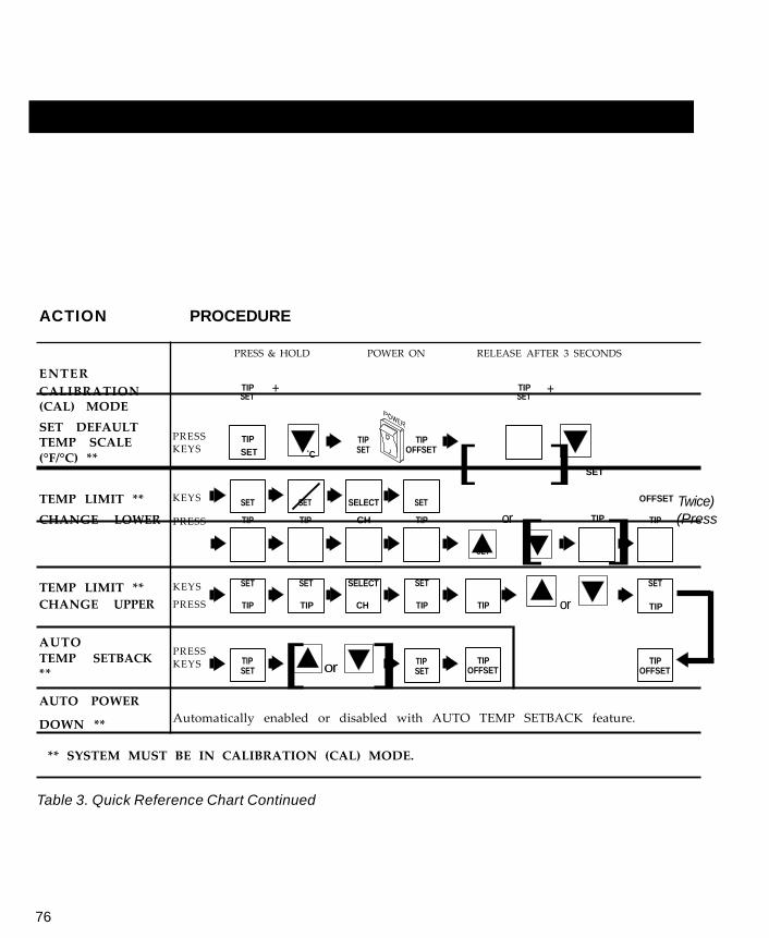
76
ACTION PROCEDURE
ENTER
PRESS & HOLD POWER ON RELEASE AFTER 3 SECONDS
CALIBRATION (CAL) MODE
SET DEFAULT TEMP SCALE (°F/°C) **
PRESS KEYS
TIP + SET
TIP ˚F
SET ˚C
TIP SET
TIP OFFSET
TIP + SET
TEMP LIMIT **
KEYS
SET
SET
SELECT
SET
[ ] SET
OFFSET Twice)
CHANGE LOWER
TEMP LIMIT **
PRESS
KEYS
TIP
SET
TIP
SET
CH
SELECT
TIP
SET
SET
or TIP
[ ] TIP
SET
(Press
CHANGE UPPER PRESS TIP TIP CH TIP TIP or TIP
AUTO
TEMP SETBACK **
PRESS KEYS
TIP SET [ or ]
TIP SET
TIP OFFSET
TIP OFFSET
AUTO POWER
DOWN ** Automatically enabled or disabled with AUTO TEMP SETBACK feature.
** SYSTEM MUST BE IN CALIBRATION (CAL) MODE.
Table 3. Quick Reference Chart Continued

77
WER
ENT
+
ACTION PROCEDURE
M A N U A L SETBACK ON
PRESS & HOLD RELEASE AFTER 1 SECOND
ALL ACTIVE + + C H A N N E L S E X I T
SETBACK ON PRESS & HOLD RELEASE AFTER 1 SECOND
A L L + + A C T I V E C H A N N E L S
PRESS & HOLD PO ON RELEASE AFTER 1 SECOND E N T E R P A S S W O R D M O D E
TIP ˚F
SET ˚C
TIP SET +
˚F ˚C
I N S T A L L PASSWORD **
P R E S S
K E Y S
NOT SET KEY
ANY KEY
ANY KEY
TIP
OFFSET
ER OLD PASSWORD ENTER NEW PASSWORD
C H A N G E PASSWORD **
P R E S S K E Y S
KEY 1
KEY 2
KEY 3
NOT SET KEY
ANY KEY
ANY KEY
TIP OFFSET
ENTER PASSWORD
R E M O V E PASSWORD **
P R E S S K E Y S
KEY 1
KEY 2
KEY 3
TIP SET
TIP OFFSET
SYSTEM MUST FIRST BE PUT IN PASSWORD MODE.
** INITIATE PROCEDURE WITHIN 5 SECONDS OR SYSTEM
WILL REVERT TO NORMAL OPERATION.
Table 3. Quick Reference Chart Continued

78
FOOT PEDAL
The foot pedal may be used with the PRC 2000 system in
two different manners as described below.
1. FOOT PEDAL Receptacle - Connection of the foot
pedal to this receptacle will allow the Pulse Heat
(PH), Pulse Plate (PP), MicroChine (MC) and Pik &
Paste (PD) features of the system to be actuated by
the foot pedal. Electrical connection from the foot
pedal to each feature is selected by positioning of
the FOOT PEDAL Selector Switch.
Figure 97. Foot Pedal Connection
Figure 98. Foot Pedal Selector Switch
2. THERMAL MANAGEMENT CENTER - The foot pedal
may be connected to any unused Output Receptacle
(CH 1, 2 or 3 or AUX 1, 2 or 3) on the rear panel of
the system. Depressing of the foot pedal when
connected in this manner, will activate the vacuum
pump to create vacuum at the SNAP-VAC Port or air
pressure at the Controllable PRESSURE Port.
Figure 99. Aux. Foot Pedal Connection

79
PIK AND PASTE
Located in the middle of the front panel of the system power source, this portion of the PRC 2000 provides
both a vacuum pick/placement capability (PIK) and a dispensing capability (PASTE) for use with a variety
of solder cremes, high viscosity fluxes and adhesives. Refer to the “Capabilities” portion of this manual for
a complete description of this feature. Following are the Set-Up and Operation instructions for each
feature.
PASTE DISPENSER
SET-UP
1. Install the Dispenser Cubby (PACE P/N 6019-0038)
provided with the system and install onto the left side
of the system power source chassis. Assembly
instructions are enclosed with the cubby.
2. Locate the Paste Dispenser Kit (PACE P/N 6993-
0152) provided with the system.
3. Attach the ridged end of the male quick connect
hose mount Fitting to the Air Hose.
Figure 100. Dispenser Cubby Mounting
Fitting Air Hose
Figure 101. Air Hose Connection
4. Insert the male quick connect hose mount Fitting
(attached to Air Hose) into the female PASTE DISP
Port.
Figure 102. Paste Dispense Connection

80
H
Cl
Bar
SET-UP CONT'D
5. Slide the Hose Clamp over the free end of the Air
Hose. Push clamp back 1 inch from the end of the
Air Hose.
6. Attach the free end of the Air Hose to the nipple on
the Barrel Adapter (10 cc adapter is supplied).
Air Hose
ose
amp
7. Secure the Air Hose to the Barrel Adapter by sliding
the Hose Clamp down over the Air Hose/Barrel
Adapter connection and screwing clamp down to
secure in position.
8. Attach the Barrel Adapter to a barrel prefilled with
material (not supplied). Place the barrel in the
Dispenser Cubby.
9. Insure that the foot pedal is connected to the FOOT
PEDAL Receptacle on the rear panel.
10. Set the FOOT PEDAL Selector Switch to the “PD”
position.
rel
Adapter
Figure 103. Barrel Adapter Connect.
Figure 104. Foot Pedal Select. Switch

81
NOTE
When the Foot Pedal Selector Switch is set in the PD position, the dispense
pump will run for a few seconds to provide a reservoir of pressurized air
necessary for proper dispensing. The pump will also cycle every 2 minutes
to maintain reservoir pressure.
OPERATION
PACE recommends that the operator become familiar with the operation of the dispenser by first applying
the material to a piece of paper or scrap PC board. Use this method to obtain the desired results for each
dispensing material and application.
MATERIALS USED FOR DISPENSING
CAUTION
Always refer to the Material Safety Data Sheet supplied with the material as
a guide for proper handling and safety precautions.
Barrels prefilled with solder creams and brazing pastes of 400,000 to 600,000 centipoise viscosity may be
dispensed using the needle size selections provided with your system.
NOTE
DO NOT attempt to dispense materials with viscosity levels lower than
400,000 centipoise. Low viscosity materials will not dispense properly.

82
MATERIAL LOADING
PACE recommends the use of prefilled barrels whenever practical to minimize any handling or safety
precaution requirements. When loading is required, adhere to all precautions recommended by the
material manufacturer. Refer to the Material Safety Data Sheet supplied with each material for information
on important safety procedures and a listing of any toxic chemical elements.
NOTE
To assure consistent dispensing, fill the barrel to a level of no more than 2/
3 of the barrel capacity.
Loading of high viscosity fluids may be accomplished using any of a number of available loading systems.

83
TIP SELECTION
Selection of the proper tip for the application is essential to obtain the optimum deposition rate and
amount. Check the specifications of the material manufacturer for recommended tip sizing. The tip size
and duration of the dispense cycle determine amount of material deposition (dot or bead size). Dispense
several dots (or beads) onto a piece of paper or scrap PC board to check for desired results.
NOTE
Never install a clogged tip. The tip may be clogged with material used in a
previous application. Install a new tip and discard after the required
dispensing operation is completed.
Listed below are the four tip sizes available from PACE.
ITEM
NO.
DESCRIPTION
PART
NUMBER
1 Dispenser Tip, .023" I.D., Pink (pkg. of 5) 1121-0409
2 Dispenser Tip, .020" I.D., Purple (pkg. of 5) 1121-0410
3 Dispenser Tip, .016" I.D., Blue (pkg. of 5) 1121-0411
4 Dispenser Tip, .013" I.D., Orange (pkg. of 5) 1121-0412
Table 4. Available Dispenser Tips
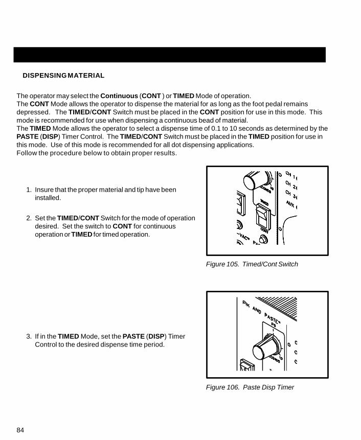
84
DISPENSING MATERIAL
The operator may select the Continuous (CONT ) or TIMED Mode of operation.
The CONT Mode allows the operator to dispense the material for as long as the foot pedal remains
depressed. The TIMED/CONT Switch must be placed in the CONT position for use in this mode. This
mode is recommended for use when dispensing a continuous bead of material.
The TIMED Mode allows the operator to select a dispense time of 0.1 to 10 seconds as determined by the
PASTE (DISP) Timer Control. The TIMED/CONT Switch must be placed in the TIMED position for use in
this mode. Use of this mode is recommended for all dot dispensing applications.
Follow the procedure below to obtain proper results.
1. Insure that the proper material and tip have been
installed.
2. Set the TIMED/CONT Switch for the mode of operation
desired. Set the switch to CONT for continuous
operation or TIMED for timed operation.
Figure 105. Timed/Cont Switch
3. If in the TIMED Mode, set the PASTE (DISP) Timer
Control to the desired dispense time period.
Figure 106. Paste Disp Timer

85
4. Holding the barrel as shown (at a 45°
angle to the work), rest the tip on a
piece of paper and dispense a small
amount of material. This initial
dispensing will fill the tip with
material.
5. Wipe any material residue from the
end of tip.
6. Hold the barrel as shown over the
work area.
7. Depress the foot pedal to dispense
material. The dispense cycle will
remain on in the CONT Mode until
the foot pedal is released. In the
TIMED Mode, the cycle will continue
for the period of time selected on the
PASTE DISP Timer Control. The
pump will turn on periodically to
maintain reservoir air pressure. The
PASTE DISP LED will illuminate
throughout the dispense cycle and
while the paste pump is running.
Figure 107. Paste Dispensing
8. Place barrel in Dispenser Cubby when dispensing operation is complete.
NOTE
Condensation may occur in the air hose after extended use. This is a
normal occurrence.
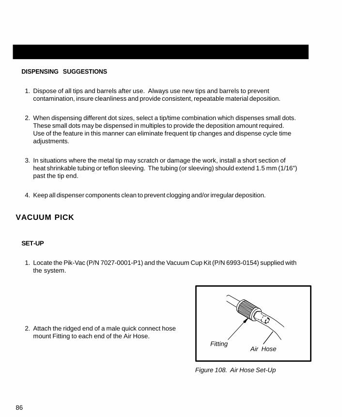
86
DISPENSING SUGGESTIONS
1. Dispose of all tips and barrels after use. Always use new tips and barrels to prevent
contamination, insure cleanliness and provide consistent, repeatable material deposition.
2. When dispensing different dot sizes, select a tip/time combination which dispenses small dots.
These small dots may be dispensed in multiples to provide the deposition amount required.
Use of the feature in this manner can eliminate frequent tip changes and dispense cycle time
adjustments.
3. In situations where the metal tip may scratch or damage the work, install a short section of
heat shrinkable tubing or teflon sleeving. The tubing (or sleeving) should extend 1.5 mm (1/16")
past the tip end.
4. Keep all dispenser components clean to prevent clogging and/or irregular deposition.
VACUUM PICK
SET-UP
1. Locate the Pik-Vac (P/N 7027-0001-P1) and the Vacuum Cup Kit (P/N 6993-0154) supplied with
the system.
2. Attach the ridged end of a male quick connect hose
mount Fitting to each end of the Air Hose.
Fitting
Air Hose
Figure 108. Air Hose Set-Up

87
3. Attach one male quick connect hose Fitting
(with attached Air Hose) to the rear of the
Pik-Vac Handpiece.
4. Insert the other male quick connect hose
Fitting (with attached Air Hose) into the PIK-
VAC Port.
5. Attach the Metal Vacuum Tip to the end of
the Pik-Vac Handpiece.
Figure 109. Pik-Vac Set-Up
OPERATION
1. Use of the Metal Vacuum Tip without a Vacuum Cup attached for removal/replacement of very
small component works well but for larger components, install one of the supplied Vacuum
Cups onto the tip. For best results, use a size slightly smaller than the body of the component
to be removed or placed. For very large components, use the largest Vacuum Cup.
2. Place the PIK-VAC Power Switch in the “ON” (1)
position to activate vacuum at the handpiece. The PIK-
VAC LED will illuminate whenever the swich is “ON”.
3. Grasp the handpiece as you would a pen with the
Vacuum Cup (or tip) pointing down and the Vacuum
Control Port (refer to illustration on following page)
pointing up.
Figure 110. Pik-Vac Power Switch

88
OPERATION CONT'D
4. Place the Vacuum Cup and/or the Metal Vacuum Tip gently onto the top surface of the
Component body. Exercise caution to avoid bending of leads on fine pitch devices.
5. Place one finger over the Vacuum Control Port. Vacuum is now being applied to the
Component body.
6. Gently lift the Component off the PC Assembly (removal operation) or out of the component
holder (placement operation).
7. Lower the Component gently into position onto the PC Assembly (placement operation) or
component holder (removal operation).
8. Lift finger or gently slide finger back from the Vacuum Control Port to release the Component.
9. Place the PIK-VAC Power Switch in the “OFF” (0) position when all Component handling
operations are completed.
PC Assembly Vacuum
Control
Port
Pik-Vac Handpiece
Component
Vacuum Cup
Figure 111. Pik-Vac Operation

89
MICROCHINE
The PACE MicroChine handpiece has a number of unique features which are not available in any other
motorized, hand-held machining tool. The user is provided with a broad range of machining capabilities
required in the repair, rework, modification, prototyping and manufacturing of printed circuit boards and
electronic assemblies.
This lightweight, variable speed, static dissipative, hand-held machining instrument offers the user a
primary handpiece with the torque and adjustable rotational speed needed to perform a number of
controlled drilling, milling and abrading tasks under varying loads.
The Probe Brake feature was developed to help you when repairing multilayer printed circuit boards. In
use, a lead is connected between the PROBE BRAKE Receptacle on the front panel of the power source
and a surface or inner layer conductor (land, trace etc.) on the circuit board. During excavation or drilling
tasks when the MicroChine drill or mill contacts this desired conductor, the brake circuit is activated and
stops the motor instantly. This allows very accurate and precise nondestructive excavation on multilayer
assemblies to the exact depth required.
The MicroChine Status Indicator LED illuminates Green in color when the MicroChine handpiece is
activated, Amber in color in maximum torque mode and Red in color when Probe Brake circuit is
activated. Electrical power input can be controlled with the integral finger switch conveniently located in
the handpiece or with the foot pedal.
SET-UP
1. Insure that the POWER Switch is in the "ON"
position.
2. Connect the MicroChine handpiece power cable
connector to the MicroChine Power
Receptacle.
Figure 112. MicroChine Attachment

90
SET-UP CONT'D
3. Adjust the MicroChine Variable Speed Control to the
desired rotational speed. Speeds are available from
2500 to 10,000 R.P.M. On any task, start with a
lower speed and increase it within your control.
Figure 113. MC-65 Speed Control
4. Select and attach the desired drill, mill or abrasive
tool for the task at hand. Insert a small drill bit into
the access hole in the MicroChine housing and shaft
to lock the shaft in position when removing or
installing a tool.
Figure 114. Tool Attachment
5. There are two power switching options, the finger
switch on the handpiece, or the foot pedal control.
When use of the foot pedal is desired, the pedal
must be attached to the FOOT PEDAL Receptacle
at the rear panel of the system power source.
Figure 115. Foot Pedal Connection

91
6. Set the FOOT PEDAL Selector Switch to the
MicroChine (MC) position when foot pedal actuation is
desired. In this mode either the finger switch on the
handpiece or the foot pedal can actuate the
MicroChine.
Figure 116. Pedal Selector Switch
7. Connect the Probe Brake Lead jack to the PROBE
BRAKE Receptacle and the clip end to a conductor
(which has continuity with the conductor (s)) you want
to protect. See “Workpiece Grounding”.
Figure 117. Probe Brake Attach.

92
PROBE BRAKE OPERATION
The MicroChine’s Probe Brake feature instantly stops all rotary machining at a selected layer depth for
nondestructive multilayer repair.
In use, the Probe Brake cable is attached to the PROBE BRAKE Receptacle on the front panel of the
system power source. The opposite end of the Probe Brake cable must be connected to a connector pin,
component lead, or a soldered-on extension of the circuit board assembly. The connection point must
have electrical continuity with the internal conductor to be repaired. A schematic diagram or layout
artwork of the printed wiring assembly (PWA) is a great aid in locating the most effective connection point
for the Probe Brake cable. The electronic Probe Brake circuit stops the MicroChine instantly when the
working drill or mill makes contact with the internal layer of circuitry, in continuity with the Probe Brake
lead, and the Status LED illuminates Red in color. Once the brake circuit has stopped the motor, the
finger switch or foot pedal must be released before the motor can be started again.
WORKPIECE GROUNDING
The Probe Brake may activate prematurely if the workpiece is attached directly to ground. The Probe
Brake circuit operates when a connection is made between the MicroChine bit and the conductor to which
the Probe Brake Lead clip is attached; a low current flows through this connection to activate the Probe
Brake. Low resistance to ground or high capacitance in the workpiece circuit connected to the Probe
Brake lead may activate the electronic sensing circuitry, in continuity with the Probe Brake lead, in the
system power source. In this case, PACE recommends the use of the PROBE BRAKE Receptacle to
ground the workpiece. To prevent electrostatic build-up, this receptacle provides an impedance of 1,000
ohms to ground.
Figure 118. Workpiece Grounding

93
PULSE PLATE
The PACE PRC 2000 system provides the DC electrical power, voltage level control power receptacles and
LED indicator for controlled miniature plating. The LED indicator illuminates Green during normal
operation and Red in short circuit or over current conditions.
Electronic current sensing and switching is built into the pulse plating power supply. This innovative
capability protects the workpiece from burning and from electrical arcing should the carbon electrode
become exposed through the cotton swab during the swab plating process.
SET-UP
1. Set the POWER switch to the “ON” (1) position.
Figure 119. Power On
2. Set FOOT PEDAL Selector Switch to the PULSE
PLATE (PP) position.
Figure 120. F.P. Selector Switch

94
SET-UP CONT'D
3. Insure that the foot pedal is attached to the
FOOT PEDAL Receptacle on the rear panel of
the power source.
Figure 121. Foot Pedal Connection
4. Place foot pedal in a convenient position on the floor beneath the workstation.
5. Open the Model PE-210 SwaPlater Kit and study the enclosed operation manual if you are not
familiar with the system.
6. Remove the two power cords from the SwaPlater case.
7. Attach the Swatplater power cords to the PULSE PLATE Outputs. Connect the Black power
cord to the Black (-) receptacle and the Red power cord to the Red (+) receptacle.
8. Set the PULSE PLATE Output Control to the proper voltage for the plating task required. See
Swaplater Model PE-210 Operation and Maintenance Manual for complete details on plating
procedure.
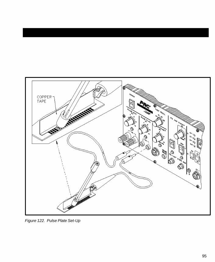
95
Figure 122. Pulse Plate Set-Up

96

97
PULSE HEAT
Located on the extreme left side of the PRC 2000 system, the PULSE HEAT section features a power
output which provides controlled temperature ramp-up to solder reflow and rapid cool down. This
controlled temperature ramp-up helps reduce the risk of thermal shock damage to components and
substrates in combination with other measures such as preheating with the PACE HotSpot. A variety of
rapid connect/disconnect handpieces allow the operator to perform many different SMD removal/
replacement tasks which may be required for any particular repair process. Refer to the “Capabilities”
portion of this manual for a complete description of
PULSE HEAT functions.
SET-UP
1. Install the Redi-Rak handpiece storage holder
onto the top of the system power source.
Complete installation instructions are included
with the Redi-Rak.
2. Insure that the foot pedal connector plug has
been connected to the FOOT PEDAL
Receptacle located on the rear panel of the
power source.
3. Set the PULSE HEAT Output Control to “0”.
Figure 123. Foot Pedal Connection
Figure 124. Pulse Heat Control

98
SET-UP CONT'D
4. Attach the Universal Power Cord to the
PULSE HEAT Outputs as shown.
5. Attach the proper tip for the task at hand, to
the selected handpiece. Refer to the Pulse
Heat Reference Guidelines for recommended
tip/handpiece selection and PULSE HEAT
Output Control settings.
6. Attach selected handpiece to the Universal
Power Cord as shown.
7. Insure that the PULSE HEAT Output Control
is adjusted to “0”.
Universal Power Cord
Figure 125. Universal Power Cord
Figure 126. Handpiece Attachment

99
OPERATION
1. Set the FOOT PEDAL Selector Switch on the system
front panel to the Pulse Heat (PH) position.
Figure 127. Pedal Selector Switch
2. Press foot pedal and adjust the PULSE HEAT Output
Control. Increase output level until selected tip heats
to desired level. The Green colored Pulse Heat LED
will remain illuminated as long as the foot pedal is
depressed.
Figure 128. Pulse Heat Output
CAUTION
Overheating and premature failure of tips may result if a high level of power
is applied and/or the tip is not in direct contact with a solder joint(s). In most
cases, the tip should not be heated unless in contact with a solder joint(s).
3. Refer to handpiece manual for recommended component removal/replacement procedures.
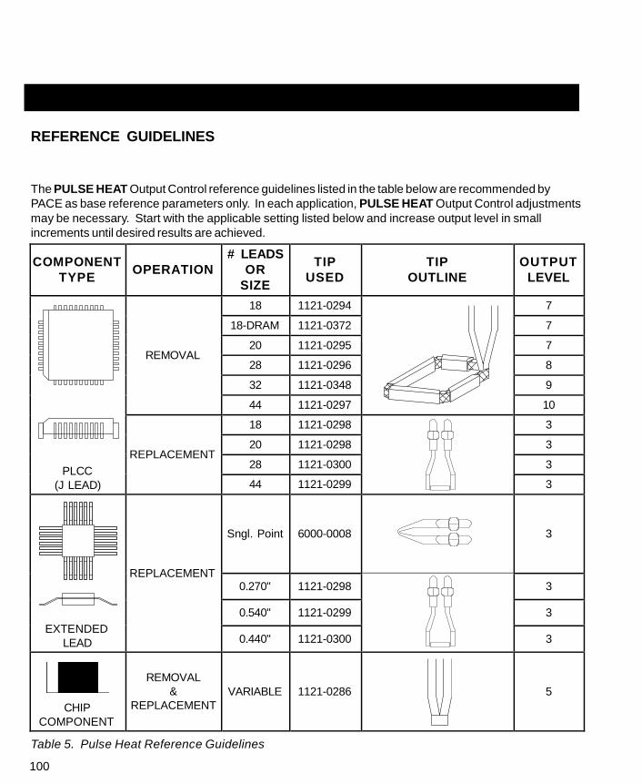
100
REFERENCE GUIDELINES
The PULSE HEAT Output Control reference guidelines listed in the table below are recommended by
PACE as base reference parameters only. In each application, PULSE HEAT Output Control adjustments
may be necessary. Start with the applicable setting listed below and increase output level in small
increments until desired results are achieved.
COMPONENT
TYPE
OPERATION
# LEADS
OR
SIZE
TIP
USED
TIP
OUTLINE
OUTPUT
LEVEL
PLCC
(J LEAD)
REMOVAL
18 1121-0294 7
18-DRAM 1121-0372 7
20 1121-0295 7
28 1121-0296 8
32 1121-0348 9
44 1121-0297 10
REPLACEMENT
18 1121-0298 3
20 1121-0298 3
28 1121-0300 3
44 1121-0299 3
EXTENDED
LEAD
REPLACEMENT
Sngl. Point
6000-0008
3
0.270" 1121-0298 3
0.540" 1121-0299 3
0.440" 1121-0300 3
CHIP
COMPONENT
REMOVAL
&
REPLACEMENT
VARIABLE
1121-0286
5
Table 5. Pulse Heat Reference Guidelines

101
CAUTION
For continuous use, the Output Level settings listed in Table 5 are the
maximum recommended values. Exceeding these levels for extended
periods may sometimes cause the handle to get hot.
COMPONENT
TYPE
OPERATION
# LEADS
OR
SIZE
TIP
USED
TIP
OUTLINE
OUTPUT
LEVEL
REMOVAL
&
REPLACEMENT
3
1121-0269
7
SOT
SOIC
REMOVAL
8 1121-0269 6
14, 16 1121-0271 6.5
20 1121-0270 6.5
24, 28 1121-0293 6.5
CONNECTOR
TERMINAL
SOLDERING
REMOVAL
&
REPLACEMENT
ANY
1121-0301
6
1121-0009
6
1121-0006
6
COATING
REMOVAL
REMOVAL
POLY U 6000-0009
2
EPOXY 2.5
WIRE
STRIP
REMOVAL
PVC, RBR 1121-0003
2 - 3
TEFLON 3 - 6
Table 5. Pulse Heat Reference Guidelines Cont'd

102
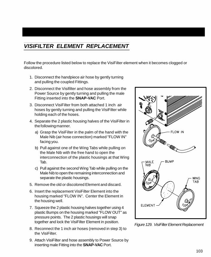
103
VISIFILTER ELEMENT REPLACEMENT
Follow the procedure listed below to replace the VisiFilter element when it becomes clogged or
discolored.
1. Disconnect the handpiece air hose by gently turning
and pulling the coupled Fittings.
2. Disconnect the Visifilter and hose assembly from the
Power Source by gently turning and pulling the male
Fitting inserted into the SNAP-VAC Port.
3. Disconnect VisiFilter from both attached 1 inch air
hoses by gently turning and pulling the VisiFilter while
holding each of the hoses.
4. Separate the 2 plastic housing halves of the VisiFilter in
the following manner.
a) Grasp the VisiFilter in the palm of the hand with the
Male Nib (air hose connection) marked "FLOW IN"
facing you.
b) Pull against one of the Wing Tabs while pulling on
the Male Nib with the free hand to open the
interconnection of the plastic housings at that Wing
Tab.
c) Pull against the second Wing Tab while pulling on the
Male Nib to open the remaining interconnection and
separate the plastic housings.
5. Remove the old or discolored Element and discard.
6. Insert the replacement VisiFilter Element into the
housing marked "FLOW IN". Center the Element in
the housing well.
7. Squeeze the 2 plastic housing halves together using 4
plastic Bumps on the housing marked "FLOW OUT" as
pressure points. The 2 plastic housings will snap
together and lock the VisiFilter Element in position.
8. Reconnect the 1 inch air hoses (removed in step 3) to
the VisiFilter.
9. Attach VisiFilter and hose assembly to Power Source by
inserting male Fitting into the SNAP-VAC Port.
Figure 129. VisiFilter Element Replacement
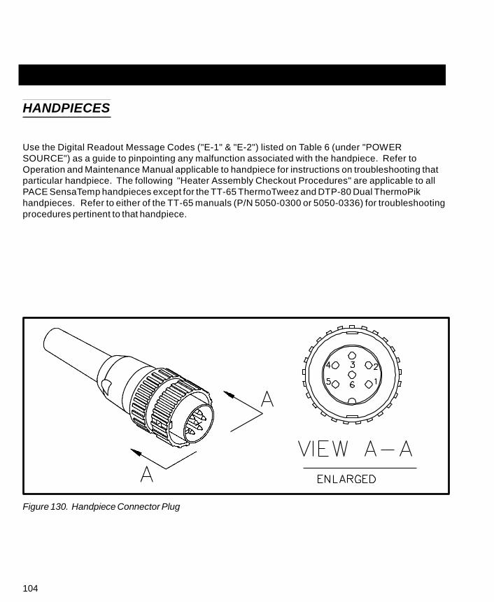
104
HANDPIECES
Use the Digital Readout Message Codes ("E-1" & "E-2") listed on Table 6 (under "POWER
SOURCE") as a guide to pinpointing any malfunction associated with the handpiece. Refer to
Operation and Maintenance Manual applicable to handpiece for instructions on troubleshooting that
particular handpiece. The following "Heater Assembly Checkout Procedures" are applicable to all
PACE SensaTemp handpieces except for the TT-65 ThermoTweez and DTP-80 Dual ThermoPik
handpieces. Refer to either of the TT-65 manuals (P/N 5050-0300 or 5050-0336) for troubleshooting
procedures pertinent to that handpiece.
Figure 130. Handpiece Connector Plug

105
NOTE
Perform the "Heater Assembly Checkout Procedures" shown below with the
handpiece (and heater) at room temperature. If the handpiece is warm,
resistance reading will be different from those shown in the table below.
SYMPTOM CHECKOUT PROCEDURE CAUSE SOLUTION HEATER
SPECIFICATIONS
No heat Check resistance - Pin 2 to Pin 5.
Refer to "Heater Specifications" column. Replace Heater
If resistance is high - - Open Heater Assembly.
SX-70 = 8 - 10 ohms
SP-1A = 10 - 12 ohms
SP-2A = 8 - 10 ohms
TP-65 = 9 - 11 ohms
TJ-70 = 6 - 8 ohms
Check resistance - Pin 3 to Pin 6. Replace Heater
If circuit reads open - - Open Sensor Assembly.
Handpiece Check resistance - Pin 3 to Pin 6. overheating Resistance should be 110 ohms.
If resistance reading is less than Replace Heater
105 ohms - - Shorted Sensor Assembly.
Fuse blows Check resistance - Pin 2 to Pin 5.
when unit is Refer to "Heater Specifications"
turned on. column.
If resistance is low - -
Remove Short.
Solder short in Replace Heater
Handpiece. Assembly & Fuse F1.
Shorted Heater Replace Heater
Assembly & Fuse F1.
No Ground Check resistance - Pin 4 to a
on Tip. NEW Tip. Resistance should be
less than 2 ohms.
If not - -
Clean Heater Bore
Oxidation buildup using appropriate wire
in Heater Bore. brush.
Defective Heater Replace Heater
Assembly.
Table 6. Heater Assembly Checkout Procedures
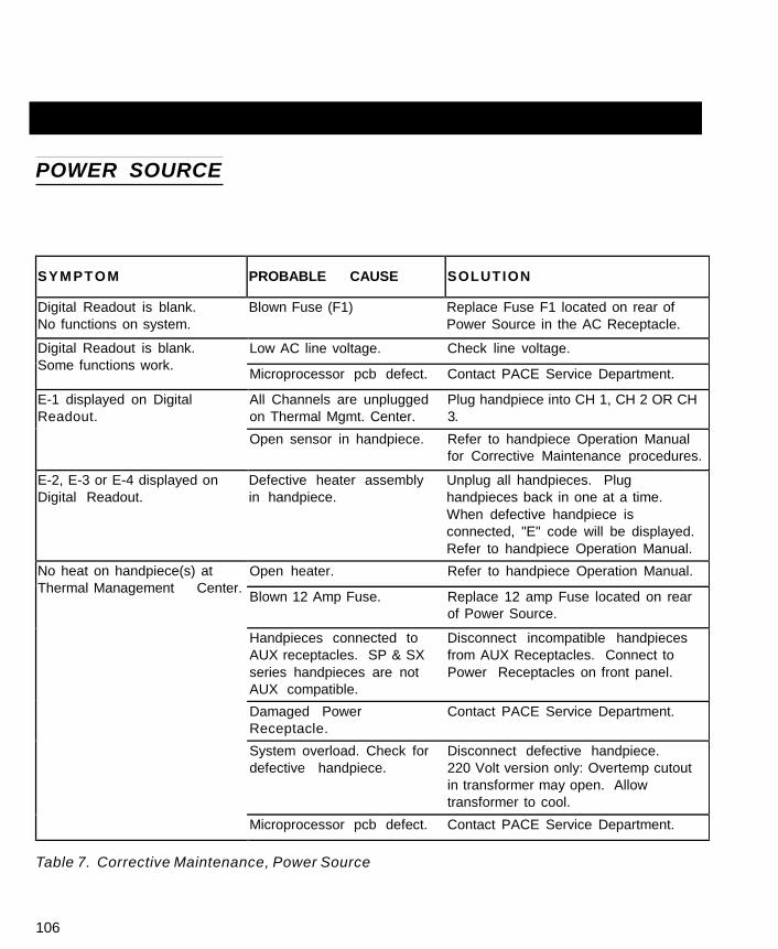
106
POWER SOURCE
SYM PTOM
PROBABLE CAUSE
SOLUTION
Digital Readout is blank. Blown Fuse (F1) Replace Fuse F1 located on rear of
No functions on system. Power Source in the AC Receptacle.
Digital Readout is blank.
Some functions work.
Low AC line voltage. Check line voltage.
Microprocessor pcb defect. Contact PACE Service Department.
E-1 displayed on Digital
Readout.
All Channels are unplugged Plug handpiece into CH 1, CH 2 OR CH
on Thermal Mgmt. Center. 3.
Open sensor in handpiece. Refer to handpiece Operation Manual
for Corrective Maintenance procedures.
E-2, E-3 or E-4 displayed on Defective heater assembly Unplug all handpieces. Plug
Digital Readout. in handpiece. handpieces back in one at a time.
When defective handpiece is
connected, "E" code will be displayed.
Refer to handpiece Operation Manual.
No heat on handpiece(s) at
Thermal Management Center.
Open heater. Refer to handpiece Operation Manual.
Blown 12 Amp Fuse. Replace 12 amp Fuse located on rear
of Power Source.
Handpieces connected to Disconnect incompatible handpieces
AUX receptacles. SP & SX from AUX Receptacles. Connect to
series handpieces are not Power Receptacles on front panel.
AUX compatible.
Damaged Power Contact PACE Service Department.
Receptacle.
System overload. Check for Disconnect defective handpiece.
defective handpiece. 220 Volt version only: Overtemp cutout
in transformer may open. Allow
transformer to cool.
Microprocessor pcb defect. Contact PACE Service Department.
Table 7. Corrective Maintenance, Power Source

107
SYMPTOM PROBABLE CAUSE SOLUTION
Foot Pedal does not activate
vacuum or air pressure for
Foot Pedal connected to
incorrect receptacle for
Connect Foot Pedal to any spare AUX
Power Receptacle on Thermal
Thermal Management Center. Thermal Mgt. Center motor
pump activation.
Management Center.
Keys on Thermal
Defective motor pump. Contact PACE Service Department.
Microprocessor pcb defect. Contact PACE Service Department.
Key caps binding. Clean and/or adjust Key caps.
Management Center don't
function properly.
Cannot adjust Offset or Set
Tip Temperature on Thermal
Management Center. Digital
Readout displays "P--".
Display pcb misaligned or
defective.
Microprocessor pcb
defective.
System is requesting
Password entry.
Contact PACE Service Department.
Contact PACE Service Department.
Enter Password.
Digital Readout on Thermal
Management Center is grossly
Operator forgot Password. Clear Password. See "Clearing a
Password" instructions.
System out of calibration. Wait 4 minutes for system to perform
automatic internal recalibration.
inaccurate. Shorted handpiece or
accessory connected to
AUX or Power Receptacle.
Defective Microprocessor
pcb.
Disconnect handpieces and
accessories. Repair defective
handpiece or accessory.
Contact PACE Service Department.
Table 7. Corrective Maintenance, Power Source Cont'd
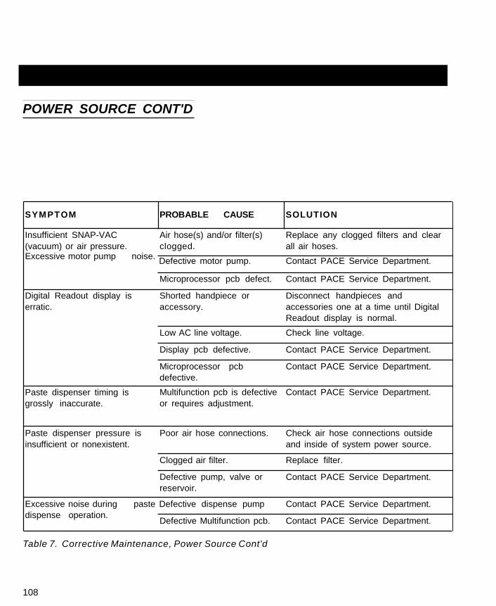
108
POWER SOURCE CONT'D
SYMPTOM PROBABLE CAUSE SOLUTION
Insufficient SNAP-VAC
(vacuum) or air pressure.
Air hose(s) and/or filter(s)
clogged.
Replace any clogged filters and clear
all air hoses. Excessive motor pump noise.
Defective motor pump. Contact PACE Service Department.
Microprocessor pcb defect. Contact PACE Service Department.
Digital Readout display is
erratic.
Shorted handpiece or
accessory.
Disconnect handpieces and
accessories one at a time until Digital
Readout display is normal.
Low AC line voltage. Check line voltage.
Display pcb defective. Contact PACE Service Department.
Paste dispenser timing is
grossly inaccurate.
Microprocessor pcb
defective.
Multifunction pcb is defective
or requires adjustment.
Contact PACE Service Department.
Contact PACE Service Department.
Paste dispenser pressure is
insufficient or nonexistent.
Poor air hose connections. Check air hose connections outside
and inside of system power source.
Clogged air filter. Replace filter.
Defective pump, valve or
reservoir.
Contact PACE Service Department.
Excessive noise during paste Defective dispense pump Contact PACE Service Department.
dispense operation.
Defective Multifunction pcb. Contact PACE Service Department.
Table 7. Corrective Maintenance, Power Source Cont'd
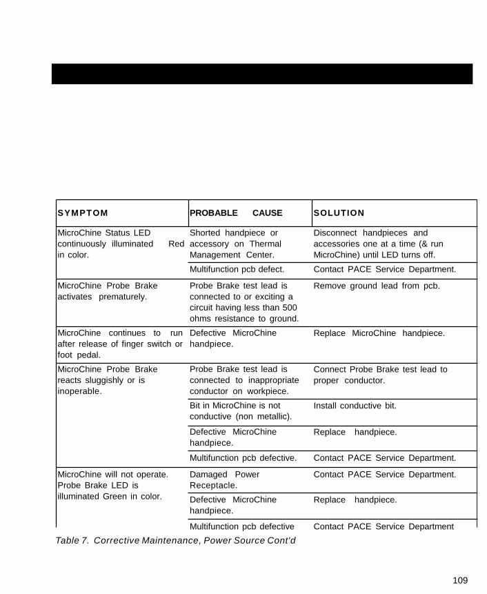
109
SYMPTOM PROBABLE CAUSE SOLUTION
MicroChine Status LED
continuously illuminated Red
in color.
Shorted handpiece or
accessory on Thermal
Management Center.
Disconnect handpieces and
accessories one at a time (& run
MicroChine) until LED turns off.
Multifunction pcb defect. Contact PACE Service Department.
MicroChine Probe Brake
activates prematurely.
MicroChine continues to run
after release of finger switch or
foot pedal.
MicroChine Probe Brake
reacts sluggishly or is
inoperable.
Probe Brake test lead is
connected to or exciting a
circuit having less than 500
ohms resistance to ground.
Defective MicroChine
handpiece.
Probe Brake test lead is
connected to inappropriate
conductor on workpiece.
Bit in MicroChine is not
conductive (non metallic).
Defective MicroChine
handpiece.
Remove ground lead from pcb.
Replace MicroChine handpiece.
Connect Probe Brake test lead to
proper conductor.
Install conductive bit.
Replace handpiece.
Multifunction pcb defective. Contact PACE Service Department.
MicroChine will not operate.
Probe Brake LED is
illuminated Green in color.
Damaged Power
Receptacle.
Defective MicroChine
handpiece.
Contact PACE Service Department.
Replace handpiece.
Multifunction pcb defective Contact PACE Service Department
Table 7. Corrective Maintenance, Power Source Cont'd

POWER SOURCE CONT'D
110
SYMPTOM
PROBABLE CAUSE
SOLUTION
MicroChine speed is grossly
inaccurate.
MicroChine is overloaded. Disengage MicroChine from workpiece.
Status LED is illuminated Resume operation exerting less
Yellow in color. pressure on handpiece.
Defective handpiece. Replace handpiece.
Multifunction pcb defective or Contact PACE Service Department.
requires adjustment.
Pik-Vac has insufficient "Low Pressure" output on Remove obstruction.
vacuum. power source rear panel is
obstructed.
Pulse Heat handpieces do
not heat. Pulse Heat LED is
illuminated Green in color.
Loose connection at Pulse Tighten connections.
Heat Outputs or handpiece
connector.
Multifunction pcb defective. Contact PACE Service Department.
Foot Pedal does not
operate in PH, PP, MP or
PD position.
Foot pedal connected to Connect foot pedal to receptacle on
incorrect receptacle. rear panel of power source marked
"FOOT PEDAL".
Multifunction pcb defective. Contact PACE Service Department.
Broken wire in harness. Contact PACE Service Department.
Table 7. Corrective Maintenance, Power Source Cont'd

111

POWER SOURCE
112
Listed below are the power source parts which may be ordered directly from PACE sales or your
local authorized PACE distributor. For handpiece replacement parts, refer to the associated
Operation and Maintenance Manual. To obtain power source parts other than those shown, contact
your local PACE distributor or PACE Service Department directly at Telephone (301) 490-9860, Fax
(301) 483-7030.
ITEM
NO.
DESCRIPTION
PACE PART NUMBER
PPS 400
PPS 400J
PPS 400E
1 Fuse (F1) 5.0 Amp, Time Lag 1159-0253 - - - - - - - -
2.5 Amp, Time Lag - - - - - - - - 1159-0220
2 Fuse (F2) 12.0 Amp, Fast Acting 1159-0257 1159-0257
3 Power Cord (not shown in illustration) 1332-0094 1332-0093
4 VisiFilter (not shown in illustration) 1309-0028 1309-0028
5 VisiFilter Replacement Elements 1309-0027-P50 1309-0027-P50
Table 8. Power Source Replacement Parts

113
Figure 131. Power Source Rear Panel
SYSTEM PACKAGING
The tables on the following pages detail handpieces and accessory items available for use with the
PRC 2000 systems. The handpieces and accessories supplied standard with each system version
(e.g., Standard Version) are listed in the current revision of the PACE Price/Parts book. Contact
your local authorized PACE distributor for additional information.
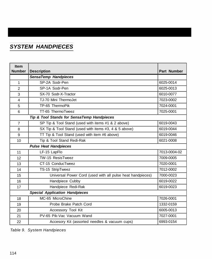
114
SYSTEM HANDPIECES
Item
Number
Description
Part Number
SensaTemp Handpieces 1 SP-2A Sodr-Pen 6025-0014
2 SP-1A Sodr-Pen 6025-0013
3 SX-70 Sodr-X-Tractor 6010-0077
4 TJ-70 Mini ThermoJet 7023-0002
5 TP-65 ThermoPik 7024-0001
6 TT-65 ThermoTweez 7025-0001
Tip & Tool Stands for SensaTemp Handpieces
7 SP Tip & Tool Stand (used with items #1 & 2 above) 6019-0043
8 SX Tip & Tool Stand (used with items #3, 4 & 5 above) 6019-0044
9 TT Tip & Tool Stand (used with item #6 above) 6019-0046
10 Tip & Tool Stand Redi-Rak 6021-0008
Pulse Heat Handpieces
11 LF-15 LapFlo 7013-0004-02
12 TW-15 ResisTweez 7009-0005
13 CT-15 ConducTweez 7020-0001
14 TS-15 StripTweez 7012-0002
15 Universal Power Cord (used with all pulse heat handpieces) 7000-0023
16 Handpiece Cubby 6019-0022
17 Handpiece Redi-Rak 6019-0023
Special Application Handpieces
18 MC-65 MicroChine 7026-0001
19 Probe Brake Patch Cord 1332-0159
20 Accessory Tool Kit 6005-0013
21 PV-65 Pik-Vac Vacuum Wand 7027-0001
22 Accesory Kit (assorted needles & vacuum cups) 6993-0154
Table 9. System Handpieces
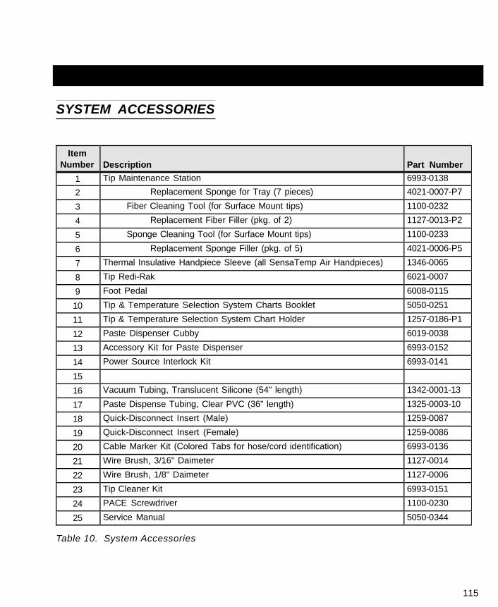
115
SYSTEM ACCESSORIES
Item
Number
Description
Part Number
1 Tip Maintenance Station 6993-0138
2 Replacement Sponge for Tray (7 pieces) 4021-0007-P7
3 Fiber Cleaning Tool (for Surface Mount tips) 1100-0232
4 Replacement Fiber Filler (pkg. of 2) 1127-0013-P2
5 Sponge Cleaning Tool (for Surface Mount tips) 1100-0233
6 Replacement Sponge Filler (pkg. of 5) 4021-0006-P5
7 Thermal Insulative Handpiece Sleeve (all SensaTemp Air Handpieces) 1346-0065
8 Tip Redi-Rak 6021-0007
9 Foot Pedal 6008-0115
10 Tip & Temperature Selection System Charts Booklet 5050-0251
11 Tip & Temperature Selection System Chart Holder 1257-0186-P1
12 Paste Dispenser Cubby 6019-0038
13 Accessory Kit for Paste Dispenser 6993-0152
14 Power Source Interlock Kit 6993-0141
15
16 Vacuum Tubing, Translucent Silicone (54" length) 1342-0001-13
17 Paste Dispense Tubing, Clear PVC (36" length) 1325-0003-10
18 Quick-Disconnect Insert (Male) 1259-0087
19 Quick-Disconnect Insert (Female) 1259-0086
20 Cable Marker Kit (Colored Tabs for hose/cord identification) 6993-0136
21 Wire Brush, 3/16" Daimeter 1127-0014
22 Wire Brush, 1/8" Daimeter 1127-0006
23 Tip Cleaner Kit 6993-0151
24 PACE Screwdriver 1100-0230
25 Service Manual 5050-0344
Table 10. System Accessories

116
SENSATEMP HANDPIECES
Listed below are available SensaTemp handpieces. These items may be ordered directly from PACE or
through your local authorized PACE distributor.
1. SP-2A Sodr-Pen Soldering Iron - P/N 6025-0014 - Provides a wide range of SMD and thru-hole
installation and removal capability as well as unsurpassed thermal performance on heavy
multilayer thru-hole assemblies at safe, lower working temperatures. A wide variety of 3/16"
shank , quick change thru-hole and SMD tips (for chip components, SOTs, SOICs and other
components) are available.
2. SP-1A Sodr-Pen Soldering Iron - P/N 6025-0013 - Uses 1/8" shank tips and features a slimmer,
more compact heater than the SP-2 Sodr-Pen for easier access on densely populated
assemblies.
3. SX-70 Sodr-X-Tractor Handpiece - P/N 6010-0077 - Provides enhanced thermal performance for
safe, rapid desoldering of heavy multilayer thru-hole solder joints. Also ideal for SMD land
preparation on heavy multilayer assemblies. A wide variety of standard, heavy duty and low
cost tips are available.
4. TP-65 ThermoPik Handpiece - P/N 7024-0001 - Provides safe one-handed reflow and removal of
a wide variety of Quad FlatPacks (PQFPs). High thermal efficiency design targets controlled
SensaTemp heat on all solder joints simultaneously without damage to the substrate or
adjacent components.
5. TT-65 ThermoTweez Handpiece - P/N 7025-0001 - Tweezer type device provides safe one-
handed reflow and removal of PLCCs and other components. High thermal capacity and
targeted heat quickly removes SMDs without damage to pcb or adjacent components.
6. TJ-70 Mini ThermoJet Handpiece - P/N 7023-0002 - Precision focused hot air reflow handpiece
provides safe, rapid installation of a wide variety of SMD components. SensaTemp control
provides safe, “on demand” capability without constant running of the air pump.
7. DTP-80 Dual ThermoPik Handpiece - P/N 7029-0001 - Provides safe one-handed reflow and
removal of a wide variety of Quad FlatPacks (PQFPs) in a matter of seconds and can even
remove BGAs (Ball Grid Arrays). High thermal efficiency design targets controlled SensaTemp
heat on all solder joints simultaneously without damage to the substrate or adjacent
components.
117
Instructions 1. Duplicate this form and submit comments on the copy. Keep the original to make future comments.
2. Complete all requested information.
3. Submit completed form to: PACE Incorporated
Applications Engineering Fax: (301) 604 - 8782
9893 Brewers Court
Laurel MD 20723-1990 U.S.A.
Document Nbr: 5050-0313 Revision Level: G Date of Submission:
Nature of Change (Identify page and paragraph and include proposed rewrite, if possible.)
Reason for Recommendation
Submitter:
Name: Company or Organization:
Mailing Address: Telephone (Include Area Code)
Voice:
Fax:
e-Mail:
Thank you for your comments; they are greatly appreciated!

118
Service
Please contact PACE or your local distributor for service and repair.
Warranty Information:
LIMITED WARRANTY
PACE warrants that this equipment will be free of defects in materials and workmanship for a period of
one (1) year from the date of receipt by original purchaser.
This warranty does not cover repair or replacement required as a result of misuse, mishandling or
improper storage. Failure to perform recommended routine maintenance, alterations or repairs made
other than in accordance with PACE’s directions, or removal or alteration of identification plates in any
way will void this warranty. This warranty is available only to the original purchaser, but the exclusions
and limitations therein apply to all persons and entities.
This warranty does not apply to consumable items, such as tips, filter elements, hoses, collection
chambers etc., except that heaters are normally warranted for a period of six (6) months from the date
of receipt by the original purchaser.
PACE MAKES NO OTHER WARRANTY, EXPRESSED OR IMPLIED, AND MAKES NO WARRANTY
OF MERCHANTABILITY OR FITNESS FOR A PARTICULAR PURPOSE.
PACE will, at its option, repair or replace any defective equipment or parts at its facility or other
location approved by PACE at no charge to the user, or provide parts without charge for installation by
the user in the field at user’s expense and risk. User will be responsible for all costs of shipping
equipment to PACE or other warranty location for warranty service.
EXCEPT FOR THE REMEDY ABOVE DESCRIBED, UNLESS OTHERWISE REQUIRED BY
APPLICABLE LAW, PACE WILL HAVE NO OTHER OBLIGATION WITH REGARD TO ANY BREACH
OF WARRANTY OR OTHER CLAIM WITH RESPECT TO THE EQUIPMENT, OR LIABILITY FOR ANY
DIRECT, INDIRECT, CONSEQUENTIAL, OR INCIDENTAL LOSS OR DAMAGE CAUSED BY OR
OCCURRING IN CONNECTION WITH ANY OF THE EQUIPMENT.
Do NOT return defective equipment or parts to PACE without obtaining prior authorization.
Any warranty or other claim with respect to the equipment must be made in writing and delivered to
PACE (or local authorized PACE Distributor outside the U.S.) within a reasonable time of the expiration
date of this warranty. Sufficient evidence of purchase and date of receipt must also be included,
otherwise user’s rights under this warranty shall be deemed waived.

119