pre-course study material - indian navy · been restricted to an introductory level to familiarise...
TRANSCRIPT
PRE-COURSE STUDY MATERIAL
SD(P) AND CHEAP COURSES PART-I
INS VALSURA
JAMNAGAR

CONTENTS
S. NO. TOPIC PAGE NO PURPOSE & SCOPE 3 Part-I Chapter 01 TECH ADMIN 4 Chapter 02 ELECTRICAL MACHINES 16 Chapter 03 POWER ELECTRONICS 32 Chapter 04 CONTROL ENGINEERING 46 Part-II Chapter 05 INSTRUMENTATION AND TEST EQUIPMENT 64

PURPOSE AND SCOPE
1. Purpose. This document has been compiled as a Pre Course Material and a source of information for Sailors undergoing SD(P) and CHEAP courses. The requirement of the document was felt to bring at par; prior to the above-mentioned courses, Sailors with different and varied backgrounds of electrical disciplines. The coverage of the topics has been restricted to an introductory level to familiarise the trainee Sailors with the basic concepts / technologies/ terms. The pre-course material only serves as a pre-cursor to further reading and must not be misconstrued as reference material in itself.
2. Scope. Based on instructor feedback and experience, the pre-course material has been compiled to cover all subjects undergoing above mention courses. 3. Utilisation & Assessment. The booklet is to be used as a preparatory document, to be read and understood prior to the corresponding subject being taught as part of the SD(P) and CHEAP course. Each chapter/ section is followed by a few basic questions which represent the expected knowledge level prior to undertaking the particular subject. The trainee may use his / her ability to answer them as a good measure of self assessment and refer to reference books indicated at the end of each chapter to be able to cope up with the course.

CHAPTER-1
TECHNICAL ADMINISTRATION
1.1. Organisation of Navy The Chief of Naval Staff (CNS) is of the rank of an Admiral and is the overall head of the integrated Headquarters of the Ministery of Defence (Navy). He is assisted by four principal staff officers (PSO's) all of whom are of the rank of Vice Admiral.
CNS
VCNS DCNS COP COM

ORGANISATION OF VCNS AT NAVAL HEADQUARTERS
VCNS
CWP&A IFA(N) ACNS(P&P) PDNP(D) DG SEABIRD DGONA DOA DGNAI
DNP DW DSR DONA DNAI
ORGANISATION OF DCNS AT NAVAL HEADQUATERS
DCNS
ACNS(IWOPS) DNI CHIEF HYDRO ACNS AIR
DNO DSOD DNOM DSMO DNS DNAS DNAM DAA

ORGANISATION OF COP AT NAVAL HEADQUARTERS
COP
DGMS(N) ACOP(HRD) DG NAVAC JAG CPS
DMS(P&M) DMS(HS) NSEC ACOP(P&C) DMPR ACOP(CIV)
DPA DCPS DCP DOP DNT DAPSA
DPS DNE DESA DNPF
ORGANISATION OF COM AT NAVAL HEADQUARTERS

COM
COL ACOM (IT & SYS) ACOM (D&R)
ACOL DNA DFM DODY DME
DCV DPRO DLS DTP
DEE DWE DIT PMG EMCAA (i) Vice Chief of the Naval Staff (VCNS) is the head of staff branch I and is responsible for planning programming, budgeting, civil works, administration, hydrography, acquisition projects, staff requirements, naval armament inspection and scientific research and development. (ii) Deputy Chief of Naval Staff (DCNS) is the head of staff branch II and responsible for surface ship and submarine operation intelligence, communication, submarine arms, oceanography and tactics and operational and material aspect of naval aviation. (iii) Chief of Personnel (COP) is responsible for recruitment, training, welfare and discipline of naval and civil personnel employed by the Navy. (iv) Chief of material (COM) is the Head of material branch and responsible for design and constructions and maintainance of ships and crafts including engeenering, electrical, and weapon aspects, armament and logistic support.
1.1.1. DRDO is responsible for the Scientific Research and development in defense technologies. DRDO has network of 51 laboratories deeply engage in developing defense technologies it is largest organisation in Asia in similar field having 5000 scientist & 25000 junior scientists and technicians. DRDO is headed by Scientific Advisor (Raksha Mantri), He

is assisted by CC(R&D) Technical & Corporate directorates and act as a interface between laboratories, Chief Controllers and Scientific Advisors. 1.1.2. DGQA Organisation is more than 100 years old and responsible for quality assurance of defense store produce by ordinance factory in public and private sector it provides quality assurance cover for Arms, Ammunitions, Equipment and stores, This Organisation is associated with DRDO in the development of project . It also ensures documentation, codification and standardization of variety of component and equipment.
1.1.3. NAVAL DOCKYARD
The primary function Naval Dockyard is timely completion of schedule refit and headed by Admiral Superintendent (Dockyard). Following are the other function of Naval Dockyard:- (i) Refit of ships and submarines and crafts (ii) Repair/Maintenance support to operational ship (iii) Arrangement of commercial dock when naval dockyards are not available (iv) Berthing and movement of ships (v) Repair to repairable inventory of MO (vi) Meeting any special requirement of Command and Naval Headquarters (vii) Upkeep of plant machinery and assets (viii) Providing yard services of ships (ix) Maintenance of yard services and crafts The Naval Dockyard Mumbai is an establishment of WNC commissioned in 1935. This establishment is headed by Admiral Superintendent (Dockyard) and he is assisted by three General Managers:-
(i) General Manager (Refit) (ii) General Manager (Technical) (iii) General Manager (Quality) The General Managers are assisted by Additional/Deputy General Managers : (i) DGM (Quality Assurance) (ii) DGM (Human Resource) (iii) DGM (Personnel &Administration) (iv) AGM/DGM (Production) (v) AGM/DGM (Planning) (vi) DGM (Weapon) The following are the DGM/Managers of production department:- (i) Manager (Fabrication) (ii) Manager (Outfitting) (iii) Manager (General Engineering & Steam)
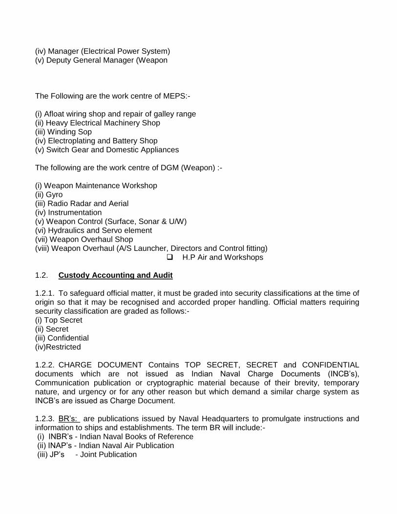
(iv) Manager (Electrical Power System) (v) Deputy General Manager (Weapon The Following are the work centre of MEPS:- (i) Afloat wiring shop and repair of galley range (ii) Heavy Electrical Machinery Shop (iii) Winding Sop (iv) Electroplating and Battery Shop (v) Switch Gear and Domestic Appliances The following are the work centre of DGM (Weapon) :- (i) Weapon Maintenance Workshop (ii) Gyro (iii) Radio Radar and Aerial (iv) Instrumentation (v) Weapon Control (Surface, Sonar & U/W) (vi) Hydraulics and Servo element (vii) Weapon Overhaul Shop (viii) Weapon Overhaul (A/S Launcher, Directors and Control fitting)
H.P Air and Workshops
1.2. Custody Accounting and Audit
1.2.1. To safeguard official matter, it must be graded into security classifications at the time of origin so that it may be recognised and accorded proper handling. Official matters requiring security classification are graded as follows:- (i) Top Secret (ii) Secret (iii) Confidential (iv)Restricted 1.2.2. CHARGE DOCUMENT Contains TOP SECRET, SECRET and CONFIDENTIAL documents which are not issued as Indian Naval Charge Documents (INCB‘s), Communication publication or cryptographic material because of their brevity, temporary nature, and urgency or for any other reason but which demand a similar charge system as INCB‘s are issued as Charge Document. 1.2.3. BR‘s: are publications issued by Naval Headquarters to promulgate instructions and information to ships and establishments. The term BR will include:- (i) INBR‘s - Indian Naval Books of Reference (ii) INAP‘s - Indian Naval Air Publication (iii) JP‘s - Joint Publication

(iv) JSP‘s - Joint Signal Publication (v) JSCP‘s - Joint Signal Communication Publication 1.2.4. Duties and Responsibilities of Accounting Officer: The accounting officer is responsible to the Commanding Officer for ensuring that:- (i) Receipt, issue and maintenance of CB/CD (ii) Keeping Supply/Receipt/Destruction notes as supporting voucher. (iii) Putting up all correspondence relating to charge books to the Commanding Officer and inform all concern officers. (iv) Ensuring that the copies of relevant orders on safe custody, ready for reference. 1.2.5 PUBLIC/NON PUBLIC FUND PUBLIC FUND: Public funds are Government money granted to ships and establishment. (i) Educational Training Grant (ii) The Trainees Educational Training Grant (iii) The General Educational Training Gran (iv) Welfare and Amenities Grant (v) Cash Grant (vi) Ship‘s Improvement Fund (vii) Ship‘s Proficiency Award Fund NON PUBLIC FUND: The purpose of maintaining of non public fund in general is to promote the welfare of the personnel of the ship by private effort. 1.2.6 D-787 : Those Stores which are not accounted in Naval Store items but area accounted in a loose leaf list of portable fittings and spare gears, D-787 has been divided into 09 groups:- Memorandum of Inspection (i) D787b - Sheet of general Index (ii) D787c - Certificate of first supply (iii) D787d - Certificate of Transfer (iv) D787e - Certificate of Paying off into Dockyard Control (v) D787f - Certificate for Final Disposal (vi) D787g - As fitted mach. Control Drawing (vii) D787h - Ship‘s Equipment Schedule (viii) D787j - List of Spares
1.3. Service Correspondence
1.3.1. Service Writing - The term ‗Service Writing‘ covers all writing originated by or on behalf of the Defence Services in official capacity. Service Writing consists of following essential elements:-Accuracy, B revity, Clarity, Relevance and Logic. Nearly every form of service writing has a frame work which consists of essentially of three parts: - Introduction, Main Body and Conclusion.

Types of Correspondence : The following types correspondence common to all three services :- Service Letter, Demi Official letter, Service Note, Government of India Letter, Letter to Civilians, Personal Application Form, Formal Letter, Service Paper, Minute of a Conference/Meeting, Appreciation, Memorandum given a torque by the rotating field. 1.3.2 Filling System Following are the filing system commonly followed:- (i) Group Subject Pack System (II) The Whitehall System (iii) Modified Whitehall System. (i) Group Subject Pack System – In this system letters are filed in hard card board covers with clips called packs. The packs are not normaly taken out at the office. Any former papers required are removed from the pack and attached to staff minute sheet for circulation. (ii) The Whitehall System - The basic principle of this system is one paper one file. It will be appreciated that subjects referred to naval headquarters are generally those beyond the powers of administrative authorities. (iii) Modified Whitehall System-In this system no outside authorities involved. One file is only generally maintained on a particular case. 1.4 Divisional Duties 1.4.1. Duties of Divisional chief - He is a link between sailors in the division and the divisional officer. He is responsible for handling personnel and service related requests from sailors of the division and projecting them to the divisional officer in a timely manner. He is expected to plan such requirements so as to ensure the department works efficiently. He has to support the divisional officer in discharging his duties towards meeting Divisional Objectives.
1.4.2. Service Document- It is an Official Document in booklet form and no sheet will be removed from this booklet SD‘s are prepare for each sailor on joining the service by initial training establishment INS Chilka. It has been divided in to six sections:-
(i)Section I - Personal Particular (P1 to 3) (ii) Section II - Service Particular (P4 to 11) (iii)Section III - Training Particular (P12 to 13) (iv)Section IV - Leave Record (P14 to 19) (v)Section V - Record of Certificate (P20) (vi) Section VI - Performance Evaluation (60 Sheets )

Recommendation for the following to be noted on page 9/10 of service documents:- RM – Recommendation for Medal (Done Away) RMG – Recommendation for Medal with Gratuity, LS and GC Medal (After 9 annual assessment) RR – Recommendation for Re-Engagement (After 12 Annual Assessments) RMM – Recommendation Meritorious Service Medal (After 16 Annual Assessments) 1.4.3 Re-Engagement: The following condition must be fulfilled for:-
Out of three assessments proceeding re-engagement sailor must have: (i) At least 2 assessments of character and efficiency not below VG, SAT (ii) Must be medically fit (iii) Must have been recommended by Commanding Officer (iv) Man power requirement of service 1.4.4 Following are the type of discharge for retiring a sailor from service:-
(i) Unsuitable (ii) SNLR (Service No Longer Required) (iii) Compassionate Ground (iv) Fraudulent Entry (v) Invaliding (vi) Pre- Mature Release (vii) On Expiry of Present Engagement 1.4.5 CW Scheme : The aim of this scheme to select deserving sailor and give them sufficient in service training so as to make them general list officer at par with entrance through other scheme. 10+2 sailors of all branches are eligible, Selection process includes:
(i) Preliminary Screening Board (ii) Written Exam (iii) Service Selection Board (iv) Interview with Medical Examination 1.4.6 Special Duty List: Promotion to SLt in the special Duty list will be made with the approval of MOD on the recommendation of the Chief of the Naval Staff. Before promoted to Sub Lieutenant in SD list he has to pass the following: (i) Preliminary Screening Board (ii) Professional Examination at Kochi (iii) SSB (iv) SD Qualifying Course (v) Promotion
(vi) Post Promotion Course (vii) Age not less than 28 yrs nor more than 37 yrs.
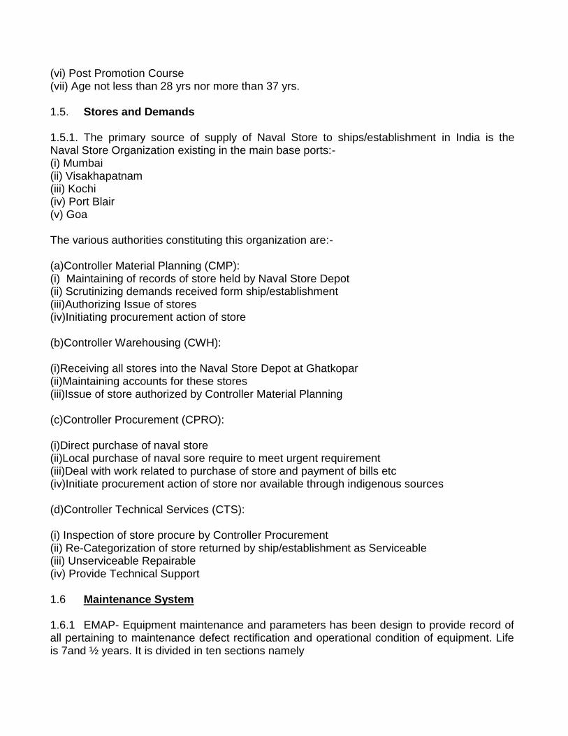
1.5. Stores and Demands 1.5.1. The primary source of supply of Naval Store to ships/establishment in India is the Naval Store Organization existing in the main base ports:- (i) Mumbai (ii) Visakhapatnam (iii) Kochi (iv) Port Blair (v) Goa The various authorities constituting this organization are:- (a)Controller Material Planning (CMP): (i) Maintaining of records of store held by Naval Store Depot (ii) Scrutinizing demands received form ship/establishment (iii)Authorizing Issue of stores (iv)Initiating procurement action of store (b)Controller Warehousing (CWH): (i)Receiving all stores into the Naval Store Depot at Ghatkopar (ii)Maintaining accounts for these stores (iii)Issue of store authorized by Controller Material Planning (c)Controller Procurement (CPRO): (i)Direct purchase of naval store (ii)Local purchase of naval sore require to meet urgent requirement (iii)Deal with work related to purchase of store and payment of bills etc (iv)Initiate procurement action of store nor available through indigenous sources (d)Controller Technical Services (CTS): (i) Inspection of store procure by Controller Procurement (ii) Re-Categorization of store returned by ship/establishment as Serviceable (iii) Unserviceable Repairable (iv) Provide Technical Support 1.6 Maintenance System 1.6.1 EMAP- Equipment maintenance and parameters has been design to provide record of all pertaining to maintenance defect rectification and operational condition of equipment. Life is 7and ½ years. It is divided in ten sections namely
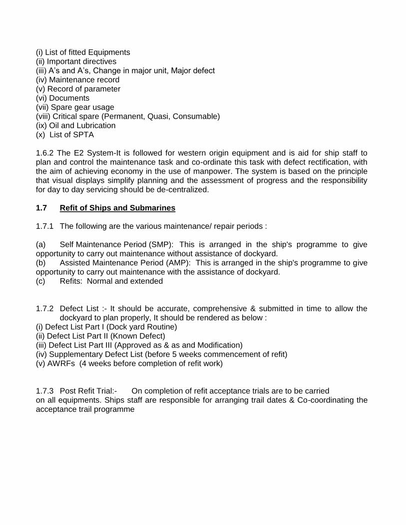
(i) List of fitted Equipments (ii) Important directives (iii) A‘s and A‘s, Change in major unit, Major defect (iv) Maintenance record (v) Record of parameter (vi) Documents (vii) Spare gear usage (viii) Critical spare (Permanent, Quasi, Consumable) (ix) Oil and Lubrication (x) List of SPTA 1.6.2 The E2 System-It is followed for western origin equipment and is aid for ship staff to plan and control the maintenance task and co-ordinate this task with defect rectification, with the aim of achieving economy in the use of manpower. The system is based on the principle that visual displays simplify planning and the assessment of progress and the responsibility for day to day servicing should be de-centralized.
1.7 Refit of Ships and Submarines 1.7.1 The following are the various maintenance/ repair periods : (a) Self Maintenance Period (SMP): This is arranged in the ship's programme to give opportunity to carry out maintenance without assistance of dockyard. (b) Assisted Maintenance Period (AMP): This is arranged in the ship's programme to give opportunity to carry out maintenance with the assistance of dockyard. (c) Refits: Normal and extended
1.7.2 Defect List :- It should be accurate, comprehensive & submitted in time to allow the
dockyard to plan properly, It should be rendered as below : (i) Defect List Part I (Dock yard Routine) (ii) Defect List Part II (Known Defect) (iii) Defect List Part III (Approved as & as and Modification) (iv) Supplementary Defect List (before 5 weeks commencement of refit) (v) AWRFs (4 weeks before completion of refit work)
1.7.3 Post Refit Trial:- On completion of refit acceptance trials are to be carried on all equipments. Ships staff are responsible for arranging trail dates & Co-coordinating the acceptance trail programme

1.8 Questions
1.8.1 Write the organisational chart of IHQ MOD (Navy)?
1.8.2 What is the role and responsibilities of DRDO?
1.8.3 Which organisation is responsible for quality assurance in Indian Navy?
1.8.4 What are the duties and responsibilities of the accounting officer?
1.8.5 What do you understand by Public and Non public fund?
1.8.6 What is the security classification of official correspondence?
1.8.7 List the type of filling used in Navy and explain each?
1.8.8 List out the forms of correspondence that are common to all three services.?
1.8.9 What are the general duties of divisional MCPO?CPO's?
1.8.10 What are the various conditions to be fulfilled before promotion?
1.8.11 List down the duties of all the Controllers in MS Organisation?
1.8.12 What is the need of survey of Naval Stores?
1.8.13 What do you understand by maintops? Who is responsible for programming it?
1.8.14 What is the occasion of rendering defect lists?
1.8.15 List down the ship staff responsibilities during refit.
1.9 Suggested Reading
VP 167:- Technical Administration

Remember: LM-RGi.e Left Hand (Rule) for Motor
&Right Hand for Generator
CHAPTER-2
ELECTRICAL MACHINES
1.2. Introduction 1.1.4. Electrical machine is the generic name for a device that converts mechanical energy to electrical energy, converts electrical energy to mechanical energy, or changes alternating current from one voltage level to a different voltage level.Electrical machines are divided into three main categories based on how they convert energy. Generators convert mechanical energy to electrical energy. Motors convert electrical energy to mechanical energy. Transformers change the voltage of alternating current. 1.1.5. Electrical machines form the building blocks for commencement of any study in electrical systems on board ships. The generation of electricity is carried by the onboard generators; the motors are used as basic prime movers for variety of systems varying from capstan to steering gear and from air blowers to drives for weapon systems. These systems are supplemented by their control circuitry such as Automatic Voltage Regulator (AVR), Governor, speed control units etc. for autonomous functioning. Further, habitability onboard ships is improved by use of refrigeration systems and air conditioning units. This chapter covers basic thumb rules of electricity and essential electrical machines that are used at various locations on a ship.
1.1.3. The functioning of electrical machines can be explained using the Fleming‘s rules. Fleming's left hand rule (for motors), and Fleming's right hand rule (for generators) is a pair of visual mnemonics that is used for working out which way an electric motor will turn, or which way the electric current will flow in an electric generator.
Fig 1.1FLEMING’S RIGHT HAND RULE: Middle finger gives the direction of flow of current in a generator

17
.
Fig 1.2FLEMING’S LEFT HAND RULE: Thumb gives the direction of motion of the motor.
1.2. Generator
1.2.5. An electric generator is a device that converts mechanical energy to electrical energy. A generator forces electrons to flow through an external electrical circuit. It is analogous to a water pump, which creates a flow of water but does not create the water inside. The source of mechanical energy, the prime mover, may be a reciprocating or turbine steam engine, water falling through a turbine or waterwheel, an internal combustion engine, a wind turbine, a hand crank, compressed air or any other source of mechanical energy. 1.2.6. There are two main parts of a generator which can be described in either mechanical or electrical terms. In mechanical terms the rotor is the rotating part of an electrical machine, and the stator is the stationary part of an electrical machine. In electrical terms the armature is the power-producing component of an electrical machine and the field is the magnetic field component of an electrical machine. The armature can be on either the rotor or the stator. The magnetic field can be provided by either electromagnets or permanent magnets mounted on either the rotor or the stator. Generators are classified into two types, AC generators and DC generators. 1.2.7. AC Generator
1.2.3.1. An AC generator converts mechanical energy into alternating current electricity. Generally, AC generators have the field winding on the rotor and the armature winding on the stator. 1.2.3.2. AC generators are classified into several types. The first is asynchronous or induction generators, in which stator flux induces currents in the rotor. The prime

18
mover then drives the rotor above the synchronous speed, causing the opposing rotor flux to cut the stator coils producing active current in the stator coils, thus sending power back to the electrical grid. The second type is synchronous generators or alternator, in which the current for the magnetic field is provided by a separate DC current source.
1.2.3.3. The turning of a coil in a magnetic field produces rotational EMFs in both sides of the coil which add. Since the component of the velocity perpendicular to the magnetic field changes sinusoidally with the rotation, the generated voltage is sinusoidal or AC. This process can be described in terms of Faraday's law when you see that the rotation of the coil continually changes the magnetic flux through the coil and therefore generates a voltage.
Fig 1.3 An AC Generator
Note: In AC Generators Slip Rings Are Used
1.2.8. DC Generator
1.2.4.1. A DC generator produces direct current electrical power from mechanical energy. A DC generator can operate at any speed within mechanical limits and always output a direct current waveform. Direct current generators known as dynamos work on exactly the same principles as alternators, but have a commutator on the rotating shaft, which converts the alternating current produced by the armature to direct current.
Fig 1.4 DC Generator

19
1.2.4.2. In DC generators the ends of the coil connect to a split ring (Fig 1.5), whose two halves are contacted by the brushes. Note that the brushes and split ring 'rectify' the EMF produced: the contacts are organised so that the current will always flow in the same direction, because when the coil turns past the dead spot, where the brushes meet the gap in the ring, the connections between the ends of the coil and external terminals are reversed.
Fig 1.5 Split Ring Commutator
1.2.5. Commutator
1.2.5.1. A commutator is a rotary electrical switch in certain types of electric motors or electrical generators that periodically reverses the current direction between the rotor and the external circuit. In a motor, it applies power to the best location on the rotor, and in a generator, picks off power similarly. As a switch, it has exceptionally long life, considering the number of circuit makes and breaks that occur in normal operation.
1.2.5.2. A commutator is a common feature of direct current rotating machines. By reversing the current direction in the moving coil of a motor's armature, a steady rotating force (torque) is produced. Similarly, in a generator, reversing of the coil's connection to the external circuit provides unidirectional direct current to the external circuit.
1.3. Motor
1.3.1. An electric motor converts electrical energy into mechanical energy. The motor functions in the reverse process of electrical generators. They operate through interacting magnetic fields and current-carrying conductors to generate rotational force. Motors and generators have many similarities and many types of electric motors can be run as generators, and vice versa. They may be powered by direct current or by alternating current which leads to the two main classifications: AC motors and DC motors. Classification of motors is shown in Fig 2.6

20
Fig 1.6 Classification of motors 1.3.1. AC Motor
1.3.1.1. An AC motor converts alternating current into mechanical energy. It commonly consists of two basic parts, an outside stationary stator having coils supplied with alternating current to produce a rotating magnetic field, and an inside rotor attached to the output shaft that is given a torque by the rotating field.
1.3.1.2. There are two main types of AC motors, depending on the type of rotor used. The first type is the induction motor, which only runs slightly slower or faster than the supply frequency. The magnetic field on the rotor of this motor is created by an induced current. The second type is the synchronous motor, which does not rely on induction and as a result, can rotate exactly at the supply frequency or a sub-multiple of the supply frequency. The magnetic field on the rotor is either generated by current delivered through slip rings or by a permanent magnet.
1.3.1.3. Induction motors are more widely used because of the following reasons:
(a) Induction motors are self-starting whereas synchronous motors are not self-starting.
(b) Speed control of Induction motor is easier as compared to synchronous motors.
(c) Maintenance of Squirrel cage induction motor is much easier than cylindrical or salient pole motors
21
1.3.2 Induction Motor
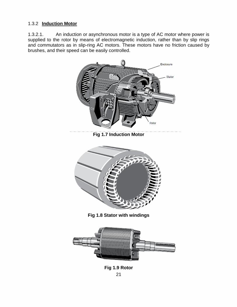
1.3.2.1. An induction or asynchronous motor is a type of AC motor where power is supplied to the rotor by means of electromagnetic induction, rather than by slip rings and commutators as in slip-ring AC motors. These motors have no friction caused by brushes, and their speed can be easily controlled.
Fig 1.7 Induction Motor
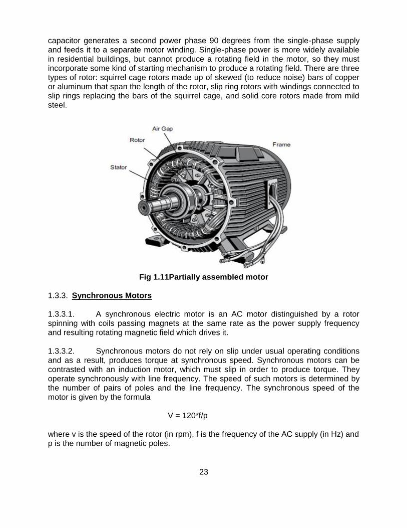
Fig 1.8 Stator with windings
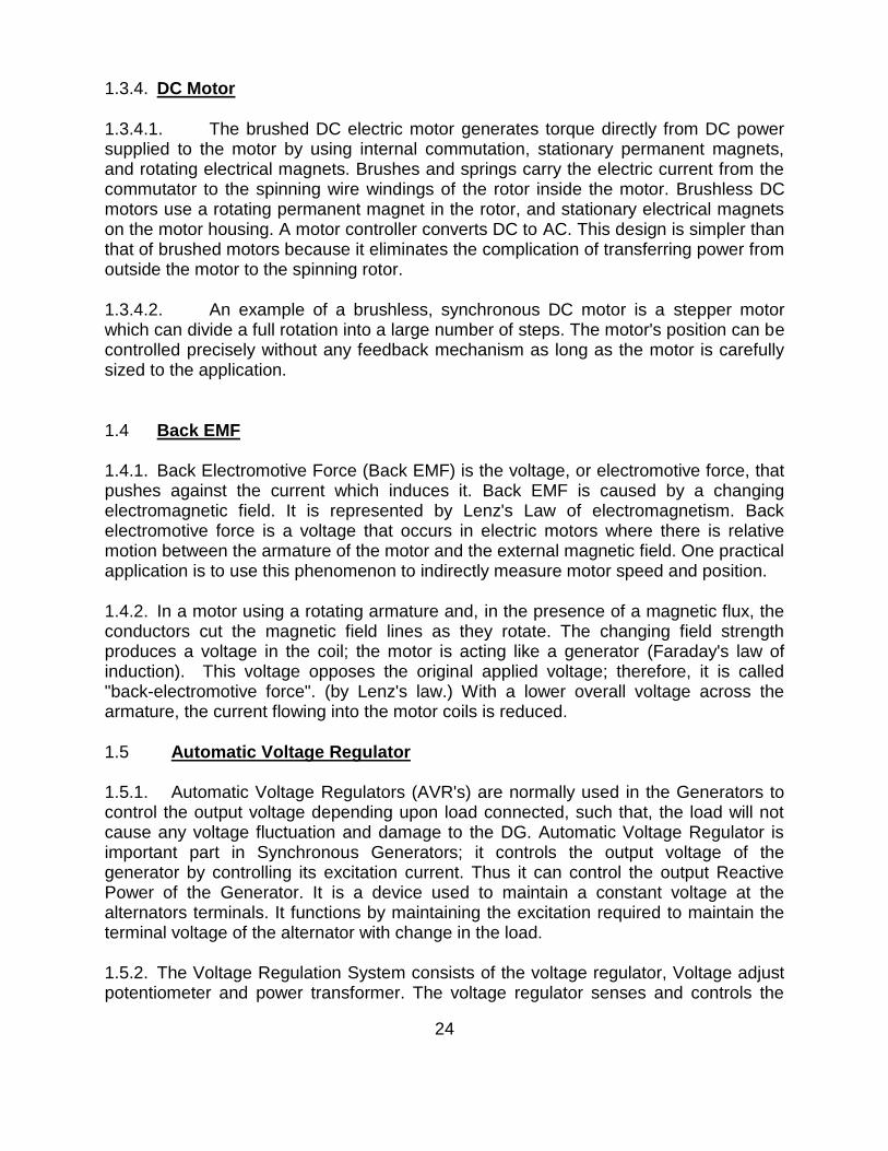
Fig 1.9 Rotor

22
1.3.2.2. An induction motor has a current induced in the rotor. Stator windings are arranged so that when energised with a polyphase supply they create a rotating magnetic field that induces current in the rotor conductors. These currents interact with the rotating magnetic field, causing rotational motion of the rotor.
1.3.2.3. For these currents to be induced, the speed of the physical rotor must be less than that of the stator's rotating magnetic field (ns), or else the magnetic field will not be moving relative to the rotor conductors and no currents will be induced. If this happens while the motor is operating, the rotor slows slightly until a current is re-induced, and it continues as before. The ratio between the speed of the magnetic field as seen by the rotor (slip speed) to the speed of the rotating stator field is unitless and is called the slip; due to this, induction motors are sometimes referred to as asynchronous machines. As well as generating rotary motion, induction motors may be run as generators or modified to directly generate linear motion.
�
Fig 1.10 Rotating Magnetic field in a 3-phase induction motor
1.3.2.4. The stator of an induction motor consists of poles carrying supply current to induce a magnetic field that penetrates the rotor. To optimize the distribution of the magnetic field, the windings are distributed in slots around the stator, with the magnetic field having the same number of north and south poles. Induction motors are most commonly run on single-phase or three-phase power, but two-phase motors exist; in theory, induction motors can have any number of phases. Many single-phase motors having two windings and a capacitor can be viewed as two-phase motors, since the
23
capacitor generates a second power phase 90 degrees from the single-phase supply and feeds it to a separate motor winding. Single-phase power is more widely available in residential buildings, but cannot produce a rotating field in the motor, so they must incorporate some kind of starting mechanism to produce a rotating field. There are three types of rotor: squirrel cage rotors made up of skewed (to reduce noise) bars of copper or aluminum that span the length of the rotor, slip ring rotors with windings connected to slip rings replacing the bars of the squirrel cage, and solid core rotors made from mild steel.
Fig 1.11Partially assembled motor
1.3.3. Synchronous Motors
1.3.3.1. A synchronous electric motor is an AC motor distinguished by a rotor spinning with coils passing magnets at the same rate as the power supply frequency and resulting rotating magnetic field which drives it.
1.3.3.2. Synchronous motors do not rely on slip under usual operating conditions and as a result, produces torque at synchronous speed. Synchronous motors can be contrasted with an induction motor, which must slip in order to produce torque. They operate synchronously with line frequency. The speed of such motors is determined by the number of pairs of poles and the line frequency. The synchronous speed of the motor is given by the formula
V = 120*f/p
where v is the speed of the rotor (in rpm), f is the frequency of the AC supply (in Hz) and p is the number of magnetic poles.
24
1.3.4. DC Motor
1.3.4.1. The brushed DC electric motor generates torque directly from DC power supplied to the motor by using internal commutation, stationary permanent magnets, and rotating electrical magnets. Brushes and springs carry the electric current from the commutator to the spinning wire windings of the rotor inside the motor. Brushless DC motors use a rotating permanent magnet in the rotor, and stationary electrical magnets on the motor housing. A motor controller converts DC to AC. This design is simpler than that of brushed motors because it eliminates the complication of transferring power from outside the motor to the spinning rotor.
1.3.4.2. An example of a brushless, synchronous DC motor is a stepper motor which can divide a full rotation into a large number of steps. The motor's position can be controlled precisely without any feedback mechanism as long as the motor is carefully sized to the application.
1.4 Back EMF 1.4.1. Back Electromotive Force (Back EMF) is the voltage, or electromotive force, that pushes against the current which induces it. Back EMF is caused by a changing electromagnetic field. It is represented by Lenz's Law of electromagnetism. Back electromotive force is a voltage that occurs in electric motors where there is relative motion between the armature of the motor and the external magnetic field. One practical application is to use this phenomenon to indirectly measure motor speed and position.
1.4.2. In a motor using a rotating armature and, in the presence of a magnetic flux, the conductors cut the magnetic field lines as they rotate. The changing field strength produces a voltage in the coil; the motor is acting like a generator (Faraday's law of induction). This voltage opposes the original applied voltage; therefore, it is called "back-electromotive force". (by Lenz's law.) With a lower overall voltage across the armature, the current flowing into the motor coils is reduced.
1.5 Automatic Voltage Regulator
1.5.1. Automatic Voltage Regulators (AVR's) are normally used in the Generators to control the output voltage depending upon load connected, such that, the load will not cause any voltage fluctuation and damage to the DG. Automatic Voltage Regulator is important part in Synchronous Generators; it controls the output voltage of the generator by controlling its excitation current. Thus it can control the output Reactive Power of the Generator. It is a device used to maintain a constant voltage at the alternators terminals. It functions by maintaining the excitation required to maintain the terminal voltage of the alternator with change in the load.
1.5.2. The Voltage Regulation System consists of the voltage regulator, Voltage adjust potentiometer and power transformer. The voltage regulator senses and controls the

25
generator output voltage which is operator adjustable within the design limits by use of the voltage adjust potentiometer. The power transformer provides operating power to the voltage regulator. The output voltage is indicated by the AC voltmeter on the control panel.
Fig 1.12 Automatic Voltage Regulator
1.6. Governor 1.6.1. A governor, or speed limiter, is a device used to measure and regulate the speed of a machine, such as a generator or an engine. The Governor Control System includes the electronic governor control, governor actuator, magnetic pickup, load measuring unit, frequency transducer, frequency meter, fuel injection pump and frequency adjust potentiometer. The governor actuator is a linear electromechanical actuator which controls the output of the fuel injection pump in response to the electrical input from the electronic governor control. The frequency adjust potentiometer, located on the control panel and adjusted by the operator, provides a signal representing the desired engine speed/generator frequency to the electronic governor control. A signal representative of the actual engine speed/generator frequency is sent to the electronic governor control by the magnetic pickup. Any change in engine speed from that selected by the operator, as sensed by the magnetic pickup, causes the electronic governor control to increase or decrease the fuel injection pump output to maintain the desired speed. The load measuring unit senses changes in external load demand and

26
provides a change signal to the electronic governor control allowing the control to start its response prior to any actual change in engine speed.
Fig 1.13 Governor System 1.7 Refrigeration 1.7.1 Refrigeration is a process in which work is done to move heat from one location to another. This work is traditionally done by mechanical work, but can also be done by magnetism, laser or other means. Refrigeration has many applications, including, but not limited to: household refrigerators, industrial freezers, cryogenics, air conditioning, and heat pumps.

27
1.7.2. Vapor-compression cycle
1.7.2.1. The vapor-compression cycle is used in most household refrigerators as well as in many large commercial and industrial refrigeration systems. Fig 2.14 provides a schematic diagram of the components of a typical vapor-compression refrigeration system.
Fig1.14Vapor compression refrigeration
1.7.2.2. The thermodynamics of the cycle can be analyzed on a diagram as shown in Figure 2.15. In this cycle, a circulating refrigerant such as Freon enters the compressor as a vapor. From point 1 to point 2, the vapor is compressed at constant entropy and exits the compressor as a vapor at a higher temperature, but still below the vapor pressure at that temperature. From point 2 to point 3 and on to point 4, the vapor travels through the condenser which cools the vapor until it starts condensing, and then condenses the vapor into a liquid by removing additional heat at constant pressure and temperature. Between points 4 and 5, the liquid refrigerant goes through the expansion valve (also called a throttle valve) where its pressure abruptly decreases, causing flash evaporation and auto-refrigeration of, typically, less than half of the liquid.

28
Fig 1.15 Temperature–Entropy diagram
1.7.2.3. This results in a mixture of liquid and vapor at a lower temperature and pressure as shown at point 5. The cold liquid-vapor mixture then travels through the evaporator coil or tubes and is completely vaporized by cooling the warm air (from the space being refrigerated) being blown by a fan across the evaporator coil or tubes. The resulting refrigerant vapor returns to the compressor inlet at point 1 to complete the thermodynamic cycle. 1.7.3. Air Conditioning 1.7.3.1. An air conditioner (often referred to as AC) is a system, or mechanism designed to dehumidify and extract heat from an area. The cooling is done using a simple refrigeration cycle. In construction, a complete system of heating, ventilation and air conditioning is referred to as "HVAC‖.
� Fig 1.16Typical Air Conditioner

29
1.7.3.2. In the refrigeration cycle of air conditioner, a heat pump transfers heat from a lower-temperature heat source into a higher-temperature heat sink. Heat would naturally flow in the opposite direction. This cycle takes advantage of the way phase changes work, where latent heat is released at a constant temperature during a liquid/gas phase change, and where varying the pressure of a pure substance also varies its condensation/boiling point. 1.7.3.3. The most common refrigeration cycle uses an electric motor to drive a compressor. In an automobile, the compressor is driven by a belt over a pulley, the belt being driven by the engine's crankshaft. Whether in a car or building, both use electric fan motors for air circulation. Since evaporation occurs when heat is absorbed, and condensation occurs when heat is released, air conditioners use a compressor to cause pressure changes between two compartments, and actively condense and pump a refrigerant around. A refrigerant is pumped into the evaporator coil, located in the compartment to be cooled, where the low pressure causes the refrigerant to evaporate into a vapor, taking heat with it. At the opposite side of the cycle is the condenser, which is located outside of the cooled compartment, where the refrigerant vapor is compressed and forced through another heat exchange coil, condensing the refrigerant into a liquid, thus rejecting the heat previously absorbed from the cooled space.
1.7.3.4. By placing the condenser (where the heat is rejected) inside a compartment, and the evaporator (which absorbs heat) in the ambient environment (such as outside), or merely running a normal air conditioner's refrigerant in the opposite direction, the overall effect is the opposite, and the compartment is heated. This is usually called a heat pump, and is capable of heating a home to comfortable temperatures (25 °C; 70 °F), even when the outside air is below the freezing point of water (0 °C; 32 °F).‘ 1.7.3.5. Cylinder unloaders are a method of load control used mainly in commercial air conditioning systems. On a semi-hermetic (or open) compressor, the heads can be fitted with unloaders which remove a portion of the load from the compressor so that it can run better when full cooling is not needed.
1.8. Questions
1.8.1. Briefly explain: brushes, split rings and commutator. 1.8.2. What is backEMF? 1.8.3. How is DC generated in DC generators? 1.8.4. Identify the following components from the illustration:
A. ________ B. ________ C. ________

30
1.8.5. The ________ is the stationary part of an AC motor‘s electromagnetic circuit. 1.8.6. The ________ is the rotating electrical part of an AC motor. 1.8.7. The ________ rotor is the most common type of rotor used in three-phase AC motors. 1.8.8. The ________ protects the internal parts of the motor from water and other environmental elements. 1.8.9. What is a synchronous motor? How is it different from Induction Motor? 1.8.10. What are various methods of speed control in a motor? 1.8.11. What is meant by slip of a motor? 1.8.12. What is the purpose of a starter for a motor? 1.8.13. What are different types of Induction motors? 1.8.14. What is the need of an AVR and governor? Are they interchangeable?
1.9. Suggested Reading
Electrical TechnologyVol II – B.L. Thareja Chapter 25
Chapter 26 Chapter 29 VP –174 :- Power Generation and Distribution

31
CHAPTER-3
POWER ELECTRONICS
1.1 Introduction 1.1.1. Power electronics is the application of solid-state electronics for the control and conversion of electric power.Power electronic converters can be found wherever there is a need to modify a form of electrical energy (i.e. change its voltage, current or frequency). The power range of these converters is from some milli-watts (as in a mobile phone) to hundreds of megawatts (e.g. in a HVDC transmission system). With "classical" electronics, electrical currents and voltage are used to carry information, whereas with power electronics, they carry power. Thus, the main metric of power electronics becomes the efficiency. Such convertors are widely used onboard ships and form the basic components of rectifiers, speed control devices, voltage conversion/ amplification, switching devices etc.
1.1.2. The first very high power electronic devices were mercury arc valves. In modern systems the conversion is performed with semiconductor switching devices such as diodes, thyristors and transistors. An AC/DC converter (rectifier) is the most typical power electronics device found in many consumer electronic devices, e.g. television sets, personal computers, battery chargers, etc. The power range is typically from tens of watts to several hundred watts. On ships the most common application is the speed control of motors, e.g., speed control of DC motors of ECM antenna in an EW system. The latest Soft starters for motors use such devices as their primary component.
1.1.3. The power conversion systems can be classified according to the type of the input and output power
(a) AC to DC (rectifier) - are used every time an electronic device is connected to the mains (computer, television etc.). These may simply change AC to DC or can also change the voltage level as part of their operation
(b) DC to AC (inverter) - are used primarily in UPS or emergency lighting systems. When mains power is available, it will charge the DC battery. If the mains fails, an inverter will be used to produce AC electricity at mains voltage from the DC battery.
(c) DC to DC (DC to DC converter) - are used in most mobile devices (mobile phones, PDA etc.) to maintain the voltage at a fixed value whatever the voltage level of the battery is. These converters are also used for electronic isolation and power factor correction
(d) AC to AC (AC to AC converter) - converters are used to change either the voltage level or the frequency (international power adapters, light dimmer). In

32
power distribution networks AC/AC converters may be used to exchange power between utility frequency 50 Hz and 60 Hz power grids.
1.2. Diode
1.2.1. Diode is a type of two-terminal electronic component with a nonlinear current–voltage characteristic. A semiconductordiodeis a crystalline piece of semiconductor material connected to two electrical terminals. A vacuumtubediode (now rarely used except in some high-power technologies) is a vacuum tube with two electrodes: a plate and a cathode.
1.2.2. The most common function of a diode is to allow an electric current to pass in one direction (called the diode's forward direction), while blocking current in the opposite direction (the reverse direction). Thus, the diode can be thought of as an electronic version of a check valve. This unidirectional behavior is called rectification, and is used to convert alternating current to direct current, and to extract modulation from radio signals in radio receivers.
1.2.3. Semiconductor diodes have nonlinear electrical characteristics, which can be tailored by varying the construction of their P–N junction. These are exploited in special purpose diodes that perform many different functions. For example, diodes are used to regulate voltage (Zenger diodes), to protect circuits from high voltage surges (Avalanche diodes), to electronically tune radio and TV receivers (reactor diodes), to generate radio frequency oscillations (tunnel diodes, Gunn diodes, IMPART diodes), and to produce light (light emitting diodes). Tunnel diodes exhibit negative resistance, which makes them useful in some types of circuits.
Fig 2.1Diode and Static I-V Characteristics of Diode
33
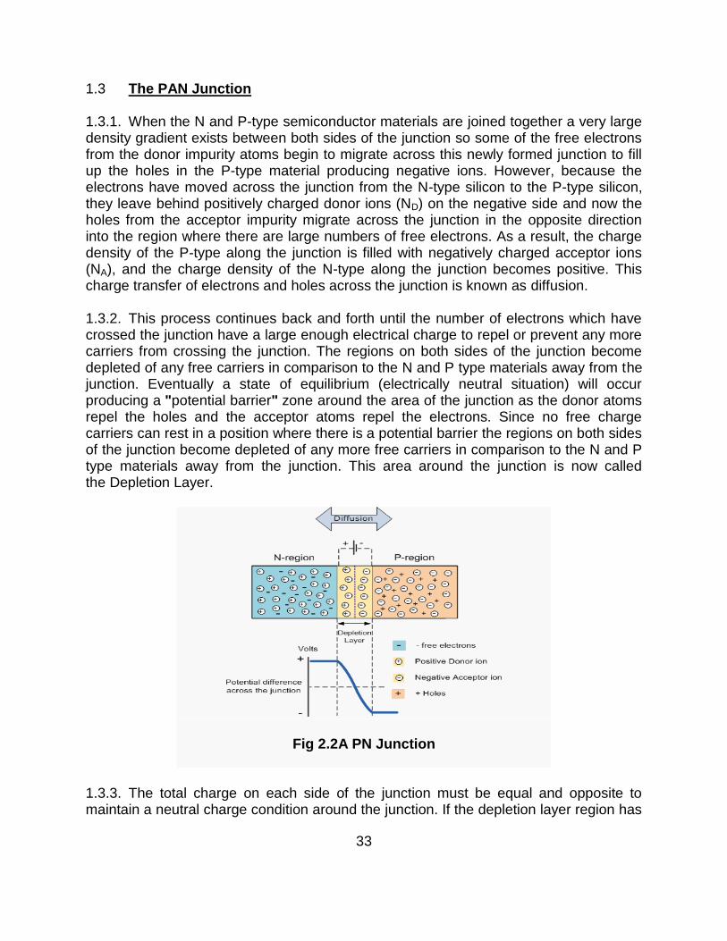
1.3 The PAN Junction 1.3.1. When the N and P-type semiconductor materials are joined together a very large density gradient exists between both sides of the junction so some of the free electrons from the donor impurity atoms begin to migrate across this newly formed junction to fill up the holes in the P-type material producing negative ions. However, because the electrons have moved across the junction from the N-type silicon to the P-type silicon, they leave behind positively charged donor ions (ND) on the negative side and now the holes from the acceptor impurity migrate across the junction in the opposite direction into the region where there are large numbers of free electrons. As a result, the charge density of the P-type along the junction is filled with negatively charged acceptor ions (NA), and the charge density of the N-type along the junction becomes positive. This charge transfer of electrons and holes across the junction is known as diffusion.
1.3.2. This process continues back and forth until the number of electrons which have crossed the junction have a large enough electrical charge to repel or prevent any more carriers from crossing the junction. The regions on both sides of the junction become depleted of any free carriers in comparison to the N and P type materials away from the junction. Eventually a state of equilibrium (electrically neutral situation) will occur producing a "potential barrier" zone around the area of the junction as the donor atoms repel the holes and the acceptor atoms repel the electrons. Since no free charge carriers can rest in a position where there is a potential barrier the regions on both sides of the junction become depleted of any more free carriers in comparison to the N and P type materials away from the junction. This area around the junction is now called the Depletion Layer.
Fig 2.2A PN Junction
1.3.3. The total charge on each side of the junction must be equal and opposite to maintain a neutral charge condition around the junction. If the depletion layer region has

34
a distance D, it therefore must therefore penetrate into the silicon by a distance of Dip for the positive side, and a distance of Den for the negative side giving a relationship between the two of Dp.NA = Dn.ND in order to maintain charge neutrality also called equilibrium.
1.3.4. The significance of this built-in potential across the junction is that it opposes both the flow of holes and electrons across the junction and is why it is called the potential barrier. In practice, a PN junction is formed within a single crystal of material rather than just simply joining or fusing together two separate pieces. Electrical contacts are also fused onto either side of the crystal to enable an electrical connection to be made to an external circuit. Then the resulting device that has been made is called a PN junction Diode or Signal Diode
1.4 Zener Diode 1.4.1. A Zener diode is a special kind of diode which allows current to flow in the forward direction same as an ideal diode, but will also permit it to flow in the reverse direction when the voltage is above a certain value known as the breakdown voltage, Zener knee voltage or Zener voltage. The device was named after Clarence Zener, who discovered this electrical property.
1.4.2. A conventional solid-state diode will not allow significant current if it is reverse-biased below its reverse breakdown voltage. When the reverse bias breakdown voltage is exceeded, a conventional diode is subject to high current due to avalanche breakdown. Unless this current is limited by circuitry, the diode will be permanently damaged due to overheating. In case of large forward bias (current in the direction of the arrow), the diode exhibits a voltage drop due to its junction built-in voltage and internal resistance. The amount of the voltage drop depends on the semiconductor material and the doping concentrations.
Fig 2.3Zener Diode
1.4.3. A Zener diode exhibits almost the same properties, except the device is specially designed so as to have a greatly reduced breakdown voltage, the so-called Zener

35
voltage. By contrast with the conventional device, a reverse-biased Zener diode will exhibit a controlled breakdown and allow the current to keep the voltage across the Zener diode close to the Zener breakdown voltage.
1.4.4. The Zener diode's operation depends on the heavy doping of its p-n junction allowing electrons to tunnel from the valence band of the p-type material to the conduction band of the n-type material. In the atomic scale, this tunneling corresponds to the transport of valence band electrons into the empty conduction band states; as a result of the reduced barrier between these bands and high electric fields that are induced due to the relatively high levels of doping on both sides.
1.4.5. Another mechanism that produces a similar effect is the avalanche effect as in the avalanche diode. The two types of diode are in fact constructed the same way and both effects are present in diodes of this type. In silicon diodes up to about 5.6 volts, the Zener effect is the predominant effect and shows a marked negative temperature coefficient. Above 5.6 volts, the avalanche effect becomes predominant and exhibits a positive temperature coefficient.
1.5 Questions 2.5.1. What do you mean by Trivalent and Pentavalent impurities? Define N-Type and P-Type semiconductors. 2.5.2. If there are extra electrons in N-Type semiconductors, then are they electrically neutral? Give reasons. 2.5.3. Define Doping. 2.5.4. Define Conductors, Insulators and Semiconductors based on Energy Band Diagram. 2.5.5. What do you mean by biasing? What are various types of Biasing? 2.5.6. Define Potential Barrier. 2.5.7. How does the flow of electron takes place through the junction? 2.5.8. Study about the V-I characteristics of the PN junction or a diode. 1.6 Transistor
1.6.1. A transistor is a semiconductor device used to amplify and switch electronic signals. It is composed of a semiconductor material with at least three terminals for connection to an external circuit. A voltage or current applied to one pair of the transistor's terminals changes the current flowing through another pair of terminals. Because the controlled (output) power can be much more than the controlling (input) power, a transistor can amplify a signal. Today, some transistors are packaged individually, but many more are found embedded in integrated circuits.
1.6.2. The transistor is the fundamental building block of modern electronic devices, and is ubiquitous in modern electronic systems. Following its release in the early 1950s the transistor revolutionized the field of electronics, and paved the way for smaller and cheaper radios, calculators, and computers, among other things.

36
1.6.3. The basic construction of a transistor consists of two PN-junctions connected back to back giving rise to three terminals, viz., the Emitter (E), Base (B) and Collector (C) respectively.
1.6.4 Unijunction Transistor (UJT)
1.6.4.1. A Unijunction transistor (UJT) is an electronic semiconductor device that has only one junction. The UJT has three terminals: an emitter (E) and two bases (B1 and B2). The base is formed by lightly doped n-type bar of silicon. Two ohmic contacts B1 and B2 are attached at its ends. The emitter is of p-type and it is heavily doped. The resistance between B1 and B2, when the emitter is open-circuit is called interbase resistance.
1.6.4.2. The UJT is biased with a positive voltage between the two bases. This causes a potential drop along the length of the device. When the emitter voltage is driven approximately one diode voltage above the voltage at the point where the P diffusion (emitter) is, current will begin to flow from the emitter into the base region. Because the base region is very lightly doped, the additional current (actually charges in the base region) causes conductivity modulation which reduces the resistance of the portion of the base between the emitter junction and the B2 terminal. This reduction in resistance means that the emitter junction is more forward biased, and so even more current is injected. Overall, the effect is a negative resistance at the emitter terminal. This is what makes the UJT useful, especially in simple oscillator circuits.
1.6.4.3. In addition to its use as the active device in relaxation oscillators, one of the most important applications of UJTs or PUTs is to trigger thyristors (SCR, TRIAC, etc.). A DC voltage can be used to control a UJT or PUT circuit such that the "on-period" increases with an increase in the DC control voltage. This application is important for large AC current control.
Fig 2.4Uni Junction Transistor
1.6.5. Bipolar Transistor
1.6.5.1. A Bipolar (junction) transistor (BJT) is a three-terminal electronic device constructed of doped semiconductor material and may be used in amplifying or switching applications. Bipolar transistors are so named because their operation involves both electrons and holes. Charge flow in a BJT is due to bidirectional diffusion of charge carriers across a junction between two regions of different charge

37
concentrations. This mode of operation is contrasted with unipolar transistors, such as field-effect transistors, in which only one carrier type is involved in charge flow due to drift. By design, most of the BJT collector current is due to the flow of charges injected from a high-concentration emitter into the base where they are minority carriers that diffuse toward the collector, and so BJTs are classified as minority-carrier devices.
Fig 2.5NPNBJT with forward-biased E–B junction
and reverse-biased B–C junction
1.6.5.2. Bipolar Transistors are current regulating devices that control the amount of current flowing through them in proportion to the amount of biasing voltage applied to their base terminal acting like a current-controlled switch. The principle of operation of the two transistor types PNP and NPN, is exactly the same the only difference being in their biasing and the polarity of the power supply for each type.
1.6.5.3. As the Bipolar Transistor is a three terminal device, there are basically three possible ways to connect it within an electronic circuit with one terminal being common to both the input and output. Each method of connection responding differently to its input signal within a circuit as the static characteristics of the transistor varies with each circuit arrangement. These configurations are:
(a) Common Base Configuration - has Voltage Gain but no Current Gain.
(b) Common Emitter Configuration - has both Current and Voltage Gain. (c) Common Collector Configuration - has Current Gain but no Voltage Gain.
1.6.7. Field-effect Transistor (FET)
1.6.7.1. The Field-Effect Transistor (FET) is a transistor that relies on an electric field to control the shape and hence the conductivity of a channel of one type of charge carrier in a semiconductor material. FETs are sometimes called unipolar transistors to contrast their single-carrier-type operation with the dual-carrier-type operation of bipolar (junction) transistors (BJT). The concept of the FET predates the BJT, though it was not

38
physically implemented until afterBJTs due to the limitations of semiconductor materials and the relative ease of manufacturing BJTs compared to FETs at the time.
1.6.7.2. The FET controls the flow of electrons (or electron holes) from the source to drain by affecting the size and shape of a "conductive channel" created and influenced by voltage (or lack of voltage) applied across the gate and source terminals. This conductive channel is the "stream" through which electrons flow from source to drain.
Fig 2.6FET
1.6.7.3. In an N-channel depletion-mode device, a negative gate-to-source voltage causes a depletion region to expand in width and encroach on the channel from the sides, narrowing the channel. If the depletion region expands to completely close the channel, the resistance of the channel from source to drain becomes large, and the FET is effectively turned off like a switch. Likewise a positive gate-to-source voltage increases the channel size and allows electrons to flow easily.
1.6.7.4. JFET
1.6.7.4.1. The J-FET (Junction Field Effect Transistor) is a voltage controlled device. That is a small change in input voltage causes a large change in output current. FET operation involves an electric field which controls the flow of a charge (current) through the device. In contrast, a bipolar transistor employs a small input current to control a large output current. The source, drain, and gate terminal of the FET are analogous to the emitter, collector, and base of a bipolar transistor. The terms n-channel and p- channel refer to the material which the drain and source are connected. The schematic symbol for the p-channel and n-channel JFET are shown in fig 2.7.
Fig 2.7Schematic Symbol for the P-channel and N-channel JFET

39
1.6.7.4.2. A simplified N-channel JFET construction is shown below. Note that the drain and source connections are made to the n-channel and the gate is connected to the p material. The N material provides a current path from the drain to the source. An N-channel JFET is biased so that the drain is positive in reference to the source. On the other hand, a p-channel JFET with n material gate would be biased in reverse.
Fig 2.8JunctionFET with N-type material sandwiched between P-type materials
1.6.7.5. MOSFET
Fig 2.9BasicMOSFET Structure
1.6.7.5.1. The construction of the Metal Oxide Semiconductor FET is very different to that of the Junction FET. Both the Depletion and Enhancement type MOSFETs use an electrical field produced by a gate voltage to alter the flow of charge carriers, electrons for N-channel or holes for P-channel, through the semi-conductive drain-source channel. The gate electrode is placed on top of a very thin insulating layer and there are a pair of small N-type regions just under the drain and source electrodes. The

40
gate of a JFET must be biased in such a way as to forward-bias the PN-junction but with a insulated gate MOSFET device no such limitations apply so it is possible to bias the gate of a MOSFET in either polarity, positive or negative. This makes MOSFETs especially valuable as electronic switches or to make logic gates because with no bias they are normally non-conducting and this high gate input resistance means that very little or no control current is needed as MOSFETs are voltage controlled devices. Both the P-channel and the N-channel MOSFETs are available in two basic forms, the Enhancement type and the Depletion type. 1.7 Thyristor
2.7.1. The thyristor is a four-layer, three terminal semiconducting device, with each layer consisting of alternately N-type or P-type material, for example P-N-P-N. The main terminals anode and cathode, are across the full four layers, and the control terminal, called the gate, is attached to p-type material near to the cathode. (A variant called an SCS—Silicon Controlled Switch—brings all four layers out to terminals.) The operation of a thyristor can be understood in terms of a pair of tightly coupled bipolar junction transistors, arranged to cause the self-latching action:
Fig 2.10Symbol and Construction of a Thyristor
1.7.2. Thyristors have three states: (a) Reverse blocking mode — Voltage is applied in the direction that would be blocked by a diode (b) Forward blocking mode — Voltage is applied in the direction that would cause a diode to conduct, but the thyristor has not yet been triggered into conduction (c) Forward conducting mode — Thethyristor has been triggered into conduction and will remain conducting until the forward current drops below a threshold value known as the "holding current"
1.7.3. The thyristor has three p-n junctions (serially named J1, J2, J3 from the anode) as shown in Fig 2.11.

41
Fig 2.11Layer Diagram of Thyristor.
1.7.4. When the anode is at a positive potential VAK with respect to the cathode with no voltage applied at the gate, junctions J1 and J3 are forward biased, while junction J2 is reverse biased. As J2 is reverse biased, no conduction takes place (Off state). Now if VAK is increased beyond the breakdown voltage VBO of the thyristor, avalanche breakdown of J2takes place and the thyristor starts conducting (On state).
1.7.5. If a positive potential VG is applied at the gate terminal with respect to the cathode, the breakdown of the junction J2 occurs at a lower value of VAK. By selecting an appropriate value of VG, the thyristor can be switched into the on state suddenly. Once avalanche breakdown has occurred, the thyristor continues to conduct, irrespective of the gate voltage, until: (a) the potential VAK is removed or (b) the current through the device (anode−cathode) is less than the holding current specified by the manufacturer.
1.7.6. Thyristors are mainly used where high currents and voltages are involved, and are often used to control alternating currents, where the change of polarity of the current causes the device to switch off automatically; referred to as Zero Cross operation. The device can be said to operate synchronously as, once the device is open, it conducts current in phase with the voltage applied over its cathode to anode junction with no further gate modulation being required to replicate; the device is biased fully on. This is not to be confused with symmetrical operation, as the output is unidirectional, flowing only from cathode to anode, and so is asymmetrical in nature.
1.7.7. Thyristorsare used as the control elements for phase angle triggered controllers, also known as phase fired controllers.They can also be found in power supplies for digital circuits, where they are used as a sort of circuit breaker or crowbar to prevent a failure in the power supply from damaging downstream components. A thyristor is used in conjunction with a zener diode attached to its gate, and when the output voltage of the supply rises above the zener voltage, the thyristor will conduct, then short-circuit the power supply output to ground (and in general blowing an upstream fuse).

42
1.7.8. Thyristors associated with triggering DIAC are used in stabilized power supplies within color television receivers Thyristors have been as lighting dimmers in television, motion pictures, and theater, where they replaced inferior technologies such as autotransformers and rheostats. They have also been used in photography as a critical part of flashes (strobes).
1.8 DIAC 1.8.1. The DIAC (diode for alternating current) is a diode that conducts current only after its breakovervoltage has been reached momentarily.
1.8.2. When this occurs, diode enters the region of negative dynamic resistance, leading to a decrease in the voltage drop across the diode and, usually, a sharp increase in current through the diode. The diode remains "in conduction" until the current through it drops below a value characteristic for the device, called the holding current. Below this value, the diode switches back to its high-resistance (non-conducting) state. This behavior is bidirectional, meaning typically the same for both directions of current.
1.8.3. Most DIACs have a three-layer structure with breakover voltage around 30 V. DIACs have no gate electrode, unlike some other thyristors that they are commonly used to trigger, such as TRIACs. Some TRIACs, like Quadrac, contain a built-in DIAC in series with the TRIAC's "gate" terminal for this purpose.
1.8.4. DIACs are also called symmetrical trigger diodes due to the symmetry of their characteristic curve. Because DIACs are bidirectional devices, their terminals are not labeled as anode and cathode but as A1 and A2 or MT1 (Main Terminal) and MT2.
Fig 2.12 V-I Characteristics of DIAC

43
1.9 TRIAC 1.9.1. TRIAC (Triode for Alternating Current) isan electronic component which can conduct current in either direction when it is triggered (turned on), and is formally called a bidirectional triode thyristor or bilateral triode thyristor.
1.9.2. A TRIAC is approximately equivalent to two complementary unilateral thyristors (one is anode triggered and another is cathode triggered SCR) joined in anti-parallel
(paralleled but with the polarity reversed) and with their gates connected together. It can be triggered by either a positive or a negative voltage being applied to its gate electrode (with respect to A1, otherwise known as MT1). Once triggered, the device continues to conduct until the current through it drops below a certain threshold value, the holding current, such as at the end of a half-cycle of alternating current (AC) mains power. This makes the TRIAC a very convenient switch for AC circuits, allowing the control of very large power flows with milliampere-scale control currents. In addition, applying a trigger pulse at a controllable point in an AC cycle allows one to control the percentage of current that flows through the TRIAC to the load (phase control).
Fig 2.13TRIAC
1.9.3. Low power TRIACs are used in many applications such as light dimmers, speed controls for electric fans and other electric motors, and in the modern computerized control circuits of many small and major household appliances.
44
1.10 Questions
2.1. What do you mean by current operated and voltage operated devices? Give examples. 2.2. How are FETs and MOSFETs used as switches? 2.3. What do you mean by Depletion mode and Enhancement mode MOSFETs? 2.4. List down 03 possible applications of a thyristor/ SCR onboard ships. 2.5. Suggested Reading Power Electronics – PS Bhimraw Chapter 2 Chapter 4

45
CHAPTER-4
CONTROL SYSTEMS
1.1 Introduction 1.1.1. The complexity of the problems of man's existence is growing at an ever-increasing rate and it may be expected to continue to do so in future. As such, constantly, human effort and capacity are replaced by machines and control systems, wherever possible, so that they may be applied to other problems.
1.1.2. For the past few decades, the trend of modern civilization has been in the direction of greater control. Its importance has grown tremendously in almost every field of technical endeavor. Thermostats regulate temperature in air-conditioners, refrigerators, ovens and furnaces. Numerous control arrangements find their ways into industrial and military applications, for the control of position, speed, tension, temperature, humidity, pressure flow etc. Some specific examples are tension controllers of sheet rolls in paper mills, thickness controller of sheet metals in rolling mills, pressure controller in boilers, concentration controllers, reaction controllers etc, in chemical processes, radar, antenna sweeping control, gun direction, missile control and control in space etc.
1.2. Control System 5.2.1. A Control System is a device, or a collection of devices that manage the behavior of other devices. Some devices are not controllable. A control system is an interconnection of components connected or related in such a manner as to command, direct, or regulate itself or another system.
(a) Controller A controller is a control system that manages the behavior of another device or system. (b) Compensator A compensator is a control system that regulates another system, usually by conditioning the input or the output to that system. Compensators are typically employed to correct a single design flaw, with the intention of affecting other aspects of the design in a minimal manner.
1.3 Feedback 1.3.1. Feedback describes the situation when output from (or information about the result of) an event or phenomenon in the past will influence an occurrence or occurrences of the same (i.e. same defined) event / phenomenon (or the continuation / development of the original phenomenon) in the present or future. When an event is part of a chain of cause-and-effect that forms a circuit or loop, then the event is said to "feedback" into itself.
46
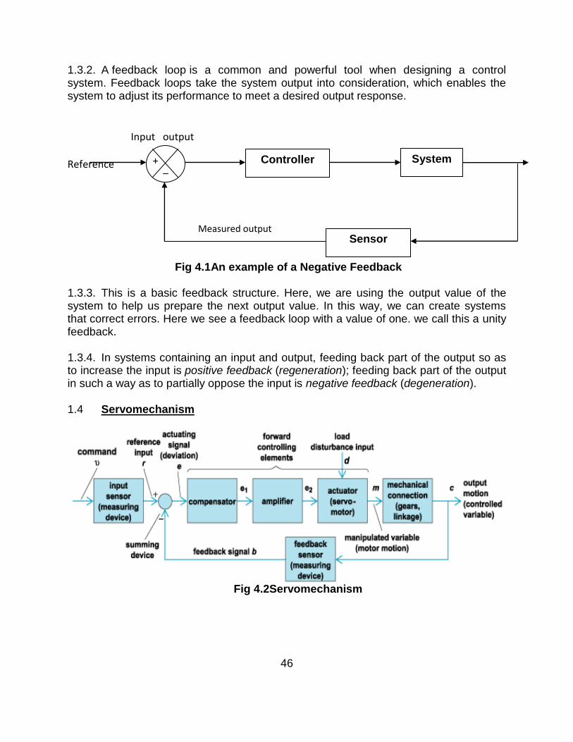
1.3.2. A feedback loop is a common and powerful tool when designing a control system. Feedback loops take the system output into consideration, which enables the system to adjust its performance to meet a desired output response.
Input output Reference Measured output
Fig 4.1An example of a Negative Feedback
1.3.3. This is a basic feedback structure. Here, we are using the output value of the system to help us prepare the next output value. In this way, we can create systems that correct errors. Here we see a feedback loop with a value of one. we call this a unity feedback.
1.3.4. In systems containing an input and output, feeding back part of the output so as to increase the input is positive feedback (regeneration); feeding back part of the output in such a way as to partially oppose the input is negative feedback (degeneration). 1.4 Servomechanism
Fig 4.2Servomechanism
Sensor
System Controller +

47
1.4.1. A servomechanism, or servo, is an automatic device that uses error-sensing negative feedback to correct the performance of a mechanism. The term correctly applies only to systems where the feedback or error-correction signals help control mechanical position, speed or other parameters. A servomechanism may or may not use a servomotor. For example, a household furnace controlled by a thermostat is a servomechanism, yet there is no motor being controlled directly by the servomechanism.
1.4.2. A common type of servo provides position control. Servos are commonly electrical or partially electronic in nature, using an electric motor as the primary means of creating mechanical force. Other types of servos use hydraulics, pneumatics, or magnetic principles. Servos operate on the principle of negative feedback, where the control input is compared to the actual position of the mechanical system as measured by some sort of transducer at the output. Any difference between the actual and wanted values (an "error signal") is amplified and used to drive the system in the direction necessary to reduce or eliminate the error. This procedure is one widely used application of control theory. 1.5 Transfer Function
Ue V
V
Fig 4.3A Negative Feedback Loop
Here r = Reference Signal e = Measured Error U = System Input V = System Output C = Controller P = System F = Sensor
1.5.1. If we assume the controller C, the plant P, and the sensor F are linear and time-invariant (i.e.: elements of their transfer function C(s), P(s), and F(s) do not depend on time), the systems above can be analysed using the Laplace transform on the variables. This gives the following relations:
F
P
C +

48
Solving for Y(s) in terms of R(s) gives:
1.5.2. The expression is referred to as the closed-loop transfer function of the system. The numerator is the forward (open-loop) gain from r to y, and the denominator is one plus the gain in going around the feedback loop,
the so-called loop gain. If , i.e. it has a large norm with each value of s,
and if , then Y(s) is approximately equal to R(s) and the output closely tracks the reference input. 1.6. Poles and Zeroes 1.6.1. Poles and Zeros of a transfer function are the frequencies for which the value of the transfer function becomes infinity or zero respectively. The values of the poles and the zeros of a system determine whether the system is stable, and how well the system performs. Control systems, in the simplest sense, can be designed simply by assigning specific values to the poles and zeros of the system.
1.6.2. Physically realizable control systems must have a number of poles greater than or equal to the number of zeros. Systems that satisfy this relationship are called proper. Let's say we have a transfer function defined as a ratio of two polynomials:
1.6.3. Where, N(s) and D(s) are simple polynomials. Zeros are the roots of N(s) (the numerator of the transfer function) obtained by setting N(s) = 0 and solving for s.Poles are the roots of D(s) (the denominator of the transfer function), obtained by setting D(s) = 0 and solving for s. Because of our restriction above, that a transfer function must not have more zeros then poles, we can state that the polynomial order of D(s) must be greater than or equal to the polynomial order of N(s). The polynomial order of a function is the value of the highest exponent in the polynomial.
1.7. Synchros
1.7.1. A synchro is a type of rotary electrical transformer that is used for measuring the angle of a rotating machine such as an antenna platform. In its general physical construction, it is much like an electric motor. The primary winding of the transformer, fixed to the rotor, is excited by an alternating current, which by electromagnetic induction, causes currents to flow in three star-connected secondary windings fixed at 120 degrees to each other on the stator. The relative magnitudes of secondary currents are measured and used to determine the angle of the rotor relative to the stator, or the

49
currents can be used to directly drive a receiver synchro that will rotate in unison with the synchro transmitter. 1.7.2. Synchros are used primarily for the rapid and accurate transmission of information between equipment and stations. Examples of such information are changes in course, speed, and range of targets or missiles; angular displacement (position) of the ship's rudder; and changes in the speed and depth of torpedoes. This information must be transmitted quickly and accurately. Synchros can provide this speed and accuracy. They are reliable, adaptable, and compact.
Fig 4.4A Simple Synchro System
1.7.3. Synchros, as stated earlier, are simply variable transformers. They differ from conventional transformers by having one primary winding (the rotor), which may be rotated through 360º and three stationary secondary windings (the stator) spaced 120º apart. It follows that the magnetic field within the synchro may also be rotated through 360º. If an iron bar or an electromagnet were placed in this field and allowed to turn freely, it would always tend to line up in the direction of the magnetic field. This is the basic principle underlying all synchro operations.

50
1.8 Test Inputs
1.8.1 Step. This represents a sudden change in input position. It is simulates the throw off due to gun recoil and is used to assess stability.
Information obtained:
Time to first crossover Overshoot ratio Steady state accuracy Damped natural frequency
1.8.2 Ramp or constant speed. A constant speed input will reveal the extent of any lag in output position and also cyclic errors due to mechanical defects. It simulates steady targets tracking and is used to eliminate static friction when ―step tuning‖ a servo.
Information obtained;
Steady state accuracy Indication of resonant frequency Presence of cyclic errors

51
1.8.3 SHM (Simple Harmonic Motion).This represents a sinusoidal change of input position over the operational range. This input is used to assess the overall accuracy of the servo which will be indicated by the peak error magnitude. Stability can also be assessed by the smoothness of the trace.
Information obtained:
Phase lag Magnification

52
1.9Time response specifications:Controlsystem is generally designed with damping less than one, i.e., oscillatory step response. Higher order control systems usually have a pair of complex conjugate poles with damping less than unity that dominate over the other poles .therefore the time response of second and higher order control system to a step input is generally of damped oscillatory nature as shown in figure next.
In specifying the transient –response characteristics of control system to a unit step input, we usually specify the following:
1. Delay time, td
2. Rise time, tr
3. Peak time, tp
4. Peak overshoot, mp
5. Settling time, ts
6. steady-state error, ess
1. Delay time, td: It is the required for the response to reach 50% of the final value
in the first attempt.
2. Rise time, tR: It is the time required for the response to rise from 0 to 100% of the
final value for the understanding system.
3. Peak time, tp: It is the time required for the response to reach the peak of time
response or the peak overshoot.
4. Settling time, ts: It is the time required for the time response to reach and stay
within a specified tolerance band (2% or5%) of its final value.
53
5. Peak overshoot,mp: It is the normalized difference between the time response
peak and the steady output and is defined as,
%Mp=c(tp)-c(∞)*100%
c(∞)
6. Steady-state error, Ess: It indicates the error between the actual output and the
desired output as ‗t‘ tends to infinity.
ess=lim[r(t)-c(t)]. t→∞
1.10Modes of Control.An automatic temperature control might consist of a valve, actuator, controller and sensor detecting the space temp in the room. The control system is said to be ‗in balance‘ when the space temp sensor does not register more or less temp than the required by the control system. What happens to the control valve when the space sensor register a change in temperature (a temp deviation) depends on the type of the control system used. The relationship between the movement of the valve and the change of temperature in the controlled medium is known as the mode of control or control actionDerivative of both these modes exist which will now be examined in greater detail. There are two basic modes of control:
(a)On/ Off- The valve is either fully open or fully closed, with no intermediate state.
(b)Continuous-The valve can move between fully open or fully closed, or be held at
any intermediate position.
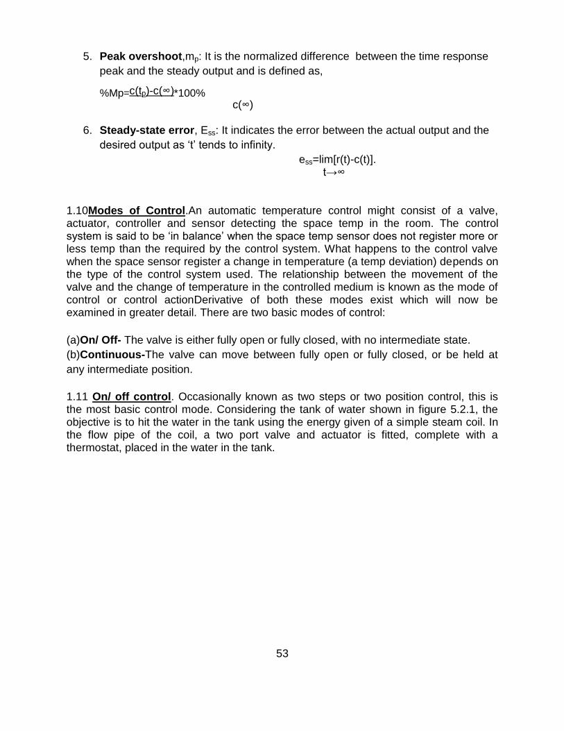
1.11 On/ off control. Occasionally known as two steps or two position control, this is the most basic control mode. Considering the tank of water shown in figure 5.2.1, the objective is to hit the water in the tank using the energy given of a simple steam coil. In the flow pipe of the coil, a two port valve and actuator is fitted, complete with a thermostat, placed in the water in the tank.
54
1.11.1. The thermostat is set to 60oC, which is the required temp of the water in the tank. Logic dictates that the switching point were actually at 60oC, the system would never operate properly, because the valve would not know whether to be open or close at 60oC. From then on it could open and shut rapidly, causing wear.
1.11.2. For this reason, the thermostat would have an upper and lower switching point. This is initial to prevent over rapid cycling (this is often referred to as ‗hunting‘ and is explained in detail later in the model). In this case the upper switching point might be 61oC (the point at which the thermostat tells the valve to shut) and the lower switching point be 59oC (the point when the valve is told to open). Thus there is an inbuilt switching difference in the thermostat of +/- 1oC about the 60oC set point.
1.11.3.This2oC (+/- 1oC) is known as the switching differential. (This will vary between thermostats). a diagram of the switching action of the thermostat would look like the graph shown in fig 5.2.2, where it is illustrated that the temp of the tank contents will fall to 59oC before the valve is asked to open and will raise to 61oC before the valve is instructed to close.

55
1.11.4.Figure 5.2.2 shows straight switching lines but the effect on heat transfer from coil to water will not be immediate. it will take time for the steam in the coil to effect the temp of the water I the tank. Not only that, but the water in the tank will rise above the 61oC upper limit and fall below the 59oC lower limit. This can be explained cross referencing fig 5.2.2 and 5.2.3. First however it is necessary to describe what is happening.
1.11.5. At point A (59oC, fig 5.2.3) the thermostat directs the valve wide open. It takes time for the transfer of heat from the coil to affect the water temp, as shown by the slope of the rise in temp in fig 5.2.3. At point B (61oC) the thermostat shuts the valve. However the coil is still full of steams, which continuous condense and give up its heat. Hence the water temp continuous to rise above the upper switching temp, and‘ overshoots‘ at C.

56
1.11.6. From this point onwards, the water temp in the tank begins to fall until, at point D (59oC), the thermostat tells the valve to open. Steam is admitted through the coil but again, it take time to have an effect and the water temp continuous to fall for a while, reaching its trough of undershoot at point E.
1.11.7. The difference between the peak and the trough is known as the operating differential. The switching differential of the thermostat depends on the type of thermostat used. The operating differential of the thermostat depends on the characteristics of the application such as the tank, its contents, and the heat transfer characteristics of the coil and so on.
1.11.8.Essentially, with on/off control, there are upper and lower switching limits and the valve is either fully open or fully closed- there is no intermediate state.The main advantages of on/off control are that it is simple and very low cost. This is why it is frequently found on domestic type applications such as central heating boilers and heater fans.Its major advantage is that the operating differential might fall outside the control tolerance required by the process. For example, on a food production line, where the taste and the repeatability of the taste are determined by precise temp control, on/ off control could well be unsuitable.
1.11.9. By contrast, in the case of space heating there are often large storage capacities (a large area to heat or cool that will respond to temp change slowly and slight variation inthe desired value is acceptable. In many cases on/off control is quite appropriate for this type of application.If on/off control is unsuitable because more accurate temp control is required, the next option is continuous control.
1.12Continuous control. Continuous control is often called modulating control. It means that the valve is capable of moving continually to change the degree of the valve opening or closing. It does not just move to either fully open or fully closed, as with on/ off control. There are three basic control actions that can apply to Continuous control:
(a) Proportional (P)
(b) Integral (I)
(c) Derivative (D)
It is also necessary to consider these I combination such as P+1, P+D, P+I+D. Although it is possible to combine the different actions, and all help to produce the required response, it is important to remember that both the integral and the derivative actions are usually corrective functions of a basic proportional control action.

57
The three control actions are considered below: 1.12.1.Proportional Control. This is most basic of the continuous control modes and is usually referred to by use of the letter ‗P‘. The principle aim of proportional control is to control the process as the condition change. This section shows that: (a) The larger the proportional band, the more stable the control, but the greater the offset. (b) The narrower the proportional band, the less stable the process, but the smaller the offset.
1.12.2. The aim, therefore, should be introduce the smallest acceptable proportional band that will always keep the process stable the minimum offset.In explaining proportional control, several new terms must be introduced. 1.12.3. To define these, a simple analogy can be considered- cold water is supplied with water via a float operative valve and with a stop valve on the outlet pipe, as shown in fig both valves are the same size and having the same flow capacity. The desired water level in the tank is at point B (equivalent to the set point of a level controller). 5.12.4. It can be assumed that, with valve ‗V‘ half open, (50% load) there is just the right flow rate of the water entering via the float operated valve to provide the desired flow out through the discharge pipe, and to maintain the water level in the tank at point at B.
1.12.5 The system can be said to be open in balance (the flow rate of water entering and leaving the tank is the same); under control, in a stable condition (the level is not varying ) and at precisely the desired water level (B); giving the required outflow.With the valve ‗V‘ closed, the level of water in the tank rises to point A and the float operated valve cuts off the water supply (see fig 5.2.5 below)(next page).

58
1.12.6. The system is still under control and stable but the control is above level B. The difference between level B and the actual control level A is related to the proportional band. Once again, if valve ‘V‘ is half opened to give 50% load, the water level in the tank will return to the desired level, point B.
1.12.7. In the fig 5.2.6 below, the valve ‗V‘ is fully opened (100 % load). The float operated valve will need to drop to open the inlet valve wide and admit a higher flow rate of water to meet the increased demand from the discharge pipe. When it reaches level C, enough water will be entering to meet the discharge needs and the water level will be maintained at point C.
1.12.8. The system is under control and stable, but there is an offset; the deviation in level between point B and C. Fig 5.2.7 combines the three conditions used in this example.The difference in level between point A and C is known as the proportional band of P-band, since this is the change in level (or temp in the case of a temp control) for the valve to move from fully open or fully close.The recognized symbol for the proportional band is Xp.

59
1.12.9. The analogy illustrates several basic and important points relating to proportional control:
(a) The valve is moved in proportional to the error in the water level (or the temp
deviation, in the case of a temp control) from the set point.
(b) The set point can only be maintained for one specific load condition.
(c) Whilst stable control will be achieved between points A and C, any load causing
a difference I level to that of B will always provide an offset.
Note: By altering the length of the float arm, the system Proportional band changes. A shorter arm gives a narrower P- band, and a longer arm gives a wider P- band. Fig 5.2.8 illustrate why this is so. A shorter arm needs less change in water level to move the angle of the arm from fully open to fully close. in both cases, it can be seen that level B represents the 50 % load level, A represents the 0% load level, and C represents the 100 % load level. It can also be seen how the offset is greater at any same load with the wider Proportional band.

60
1.12.10. For electrical and pneumatic controllers, the set value is at the middle of the Proportional band. The effect of changing the P-band for an electrical and pneumatic system can be described with a slightly different example, by using a temp control.The space temp of a building is controlled by a water (radiator type) heating system using a proportional action control by a valve driven with an electrical actuator, and an electronic controller and room sensor. The control selected has a proportional band (P-band or Xp) of 6o C and the desired internal space temp is 18o C. Under certain load conditions, the valve is 50% open and the required temp is correct at 18o C. 1.13Summary of modes of control.A three- term controller contains three modes of control:
(a) Proportional (P) action with adjustable gain to obtain stability.
(b) Reset (Integral) (I) action to compensate for load changes.
(c) Rate (Derivative) (d) action to speed up valve movement when rapid load
changes take places.
The various characteristics can be summarized, as shown in fig 5.2.17.

61
Finally the control engineer must try to avoid the danger of using unnecessarily complicated controls for a specific application. The least complicated control action, which will provide the degree of control required, should always be selected.

62
1.14. Questions 1.14.1. What do understand by servo mechanism? What is feedback? How is it advantageous or disadvantageous? 1.14.2. What do you mean by test signals? What are the various types of test signals? 1.14.3. What are synchros? What is the advantage of synchro transmission? 1.14.4. What do you mean by control transformer and differential synchros? 1.14.5. What do you mean by metadyne? 1.14.6. What is a servo chain? Where would it find application onboard? 1.14. Suggested Reading VP 193:- Control Systems Modern Control Engineering By Katsuhiko Ogata