pre-course study material - indian navy · pre-course study material sd(r) and chear courses ......
TRANSCRIPT
1
PRE-COURSE STUDY MATERIAL
SD(R) AND CHEAR COURSES
INS VALSURA
JAMNAGAR

2
CONTENTS
S. NO. TOPIC PAGE NO PURPOSE & SCOPE 3 Chapter 01 TECH ADMIN 4 Chapter 02 RADAR ENGINEERING 16 Chapter 03 COMMUNICATION ENGINEERING 29 Chapter 06 INSTRUMENTATION AND TEST EQUIPMENT 40

3
PURPOSE AND SCOPE
1. Purpose. This document has been compiled as a Pre Course Material and a source of information for Sailors undergoing SD(R) and CHEAR courses. The requirement of the document was felt to bring at par; prior to the above-mentioned courses, Sailors with different and varied backgrounds of electrical disciplines. The coverage of the topics has been restricted to an introductory level to familiarise the trainee Sailors with the basic concepts / technologies/ terms. The pre-course material only serves as a pre-cursor to further reading and must not be misconstrued as reference material in itself.
2. Scope. Based on instructor feedback and experience, the pre-course material has been compiled to cover all subjects undergoing above mention courses. 3. Utilisation & Assessment. The booklet is to be used as a preparatory document, to be read and understood prior to the corresponding subject being taught as part of the SD(R) and CHEAR course. Each chapter/ section is followed by a few basic questions which represent the expected knowledge level prior to undertaking the particular subject. The trainee may use his / her ability to answer them as a good measure of self assessment and refer to reference books indicated at the end of each chapter to be able to cope up with the course.
CHAPTER-1

4
TECHNICAL ADMINISTRATION
1.1. Organisation of Navy The Chief of Naval Staff (CNS) is of the rank of an Admiral and is the overall head of the integrated Headquarters of the Ministery of Defence (Navy). He is assisted by four principal staff officers (PSO's) all of whom are of the rank of Vice Admiral.
CNS
VCNS DCNS COP COM

5
ORGANISATION OF VCNS AT NAVAL HEADQUARTERS
VCNS
CWP&A IFA(N) ACNS(P&P) PDNP(D) DG SEABIRD DGONA DOA DGNAI
DNP DW DSR DONA DNAI
ORGANISATION OF DCNS AT NAVAL HEADQUARTERS
DCNS
ACNS(IWOPS) DNI CHIEF HYDRO ACNS AIR
DNO DSOD DNOM DSMO DNS DNAS DNAM DAA
6
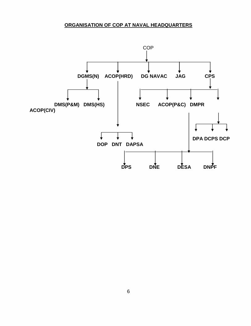
ORGANISATION OF COP AT NAVAL HEADQUARTERS
COP
DGMS(N) ACOP(HRD) DG NAVAC JAG CPS
DMS(P&M) DMS(HS) NSEC ACOP(P&C) DMPR ACOP(CIV)
DPA DCPS DCP DOP DNT DAPSA
DPS DNE DESA DNPF

7
ORGANISATION OF COM AT NAVAL HEADQUARTERS
COM
COL ACOM (IT & SYS) ACOM (D&R)
ACOL DNA DFM DODY DME
DCV DPRO DLS DTP
DEE DWE DIT PMG EMCAA (i) Vice Chief of the Naval Staff (VCNS) is the head of staff branch I and is responsible for planning programming, budgeting, civil works, administration, hydrography, acquisition projects, staff requirements, naval armament inspection and scientific research and development. (ii) Deputy Chief of Naval Staff (DCNS) is the head of staff branch II and responsible for surface ship and submarine operation intelligence, communication, submarine arms, oceanography and tactics and operational and material aspect of naval aviation. (iii) Chief of Personnel (COP) is responsible for recruitment, training, welfare and discipline of naval and civil personnel employed by the Navy. (iv) Chief of material (COM) is the Head of material branch and responsible for design and constructions and maintainance of ships and crafts including engeenering, electrical, and weapon aspects, armament and logistic support.
1.1.1. DRDO is responsible for the Scientific Research and development in defense technologies. DRDO has network of 51 laboratories deeply engage in developing defense technologies it is largest organisation in Asia in similar field having 5000 scientist & 25000 junior scientists and technicians. DRDO is headed by Scientific Advisor (Raksha Mantri),
8
He is assisted by CC(R&D) Technical & Corporate directorates and act as a interface between laboratories, Chief Controllers and Scientific Advisors. 1.1.2. DGQA Organisation is more than 100 years old and responsible for quality assurance of defense store produce by ordinance factory in public and private sector it provides quality assurance cover for Arms, Ammunitions, Equipment and stores, This Organisation is associated with DRDO in the development of project . It also ensures documentation, codification and standardization of variety of component and equipment.
1.1.3. NAVAL DOCKYARD
The primary function Naval Dockyard is timely completion of schedule refit and headed by Admiral Superintendent (Dockyard). Following are the other function of Naval Dockyard:- (i) Refit of ships and submarines and crafts (ii) Repair/Maintenance support to operational ship (iii) Arrangement of commercial dock when naval dockyards are not available (iv) Berthing and movement of ships (v) Repair to repairable inventory of MO (vi) Meeting any special requirement of Command and Naval Headquarters (vii) Upkeep of plant machinery and assets (viii) Providing yard services of ships (ix) Maintenance of yard services and crafts The Naval Dockyard Mumbai is an establishment of WNC commissioned in 1935. This establishment is headed by Admiral Superintendent (Dockyard) and he is assisted by three General Managers:-
(i) General Manager (Refit) (ii) General Manager (Technical) (iii) General Manager (Quality) The General Managers are assisted by Additional/Deputy General Managers : (i) DGM (Quality Assurance) (ii) DGM (Human Resource) (iii) DGM (Personnel &Administration) (iv) AGM/DGM (Production) (v) AGM/DGM (Planning) (vi) DGM (Weapon) The following are the DGM/Managers of production department:- (i) Manager (Fabrication) (ii) Manager (Outfitting) (iii) Manager (General Engineering & Steam)

9
(iv) Manager (Electrical Power System) (v) Deputy General Manager (Weapon The Following are the work centre of MEPS:- (i) Afloat wiring shop and repair of galley range (ii) Heavy Electrical Machinery Shop (iii) Winding Sop (iv) Electroplating and Battery Shop (v) Switch Gear and Domestic Appliances The following are the work centre of DGM (Weapon) :- (i) Weapon Maintenance Workshop (ii) Gyro (iii) Radio Radar and Aerial (iv) Instrumentation (v) Weapon Control (Surface, Sonar & U/W) (vi) Hydraulics and Servo element (vii) Weapon Overhaul Shop (viii) Weapon Overhaul (A/S Launcher, Directors and Control fitting)
H.P Air and Workshops
1.2. Custody Accounting and Audit
1.2.1. To safeguard official matter, it must be graded into security classifications at the time of origin so that it may be recognised and accorded proper handling. Official matters requiring security classification are graded as follows:- (i) Top Secret (ii) Secret (iii) Confidential (iv)Restricted 1.2.2. CHARGE DOCUMENT Contains TOP SECRET, SECRET and CONFIDENTIAL documents which are not issued as Indian Naval Charge Documents (INCB‘s), Communication publication or cryptographic material because of their brevity, temporary nature, and urgency or for any other reason but which demand a similar charge system as INCB‘s are issued as Charge Document. 1.2.3. BR‘s: are publications issued by Naval Headquarters to promulgate instructions and information to ships and establishments. The term BR will include:- (i) INBR‘s - Indian Naval Books of Reference (ii) INAP‘s - Indian Naval Air Publication (iii) JP‘s - Joint Publication

10
(iv) JSP‘s - Joint Signal Publication (v) JSCP‘s - Joint Signal Communication Publication 1.2.4. Duties and Responsibilities of Accounting Officer: The accounting officer is responsible to the Commanding Officer for ensuring that:- (i) Receipt, issue and maintenance of CB/CD (ii) Keeping Supply/Receipt/Destruction notes as supporting voucher. (iii) Putting up all correspondence relating to charge books to the Commanding Officer and inform all concern officers. (iv) Ensuring that the copies of relevant orders on safe custody, ready for reference. 1.2.5 PUBLIC/NON PUBLIC FUND PUBLIC FUND: Public funds are Government money granted to ships and establishment. (i) Educational Training Grant (ii) The Trainees Educational Training Grant (iii) The General Educational Training Gran (iv) Welfare and Amenities Grant (v) Cash Grant (vi) Ship‘s Improvement Fund (vii) Ship‘s Proficiency Award Fund NON PUBLIC FUND: The purpose of maintaining of non public fund in general is to promote the welfare of the personnel of the ship by private effort. 1.2.6 D-787 : Those Stores which are not accounted in Naval Store items but area accounted in a loose leaf list of portable fittings and spare gears, D-787 has been divided into 09 groups:- Memorandum of Inspection (i) D787b - Sheet of general Index (ii) D787c - Certificate of first supply (iii) D787d - Certificate of Transfer (iv) D787e - Certificate of Paying off into Dockyard Control (v) D787f - Certificate for Final Disposal (vi) D787g - As fitted mach. Control Drawing (vii) D787h - Ship‘s Equipment Schedule (viii) D787j - List of Spares
1.3. Service Correspondence
1.3.1. Service Writing - The term ‗Service Writing‘ covers all writing originated by or on behalf of the Defence Services in official capacity. Service Writing consists of following essential elements:-Accuracy, B revity, Clarity, Relevance and Logic. Nearly every form of service writing has a frame work which consists of essentially of three parts: - Introduction, Main Body and Conclusion.
11
Types of Correspondence : The following types correspondence common to all three services :- Service Letter, Demi Official letter, Service Note, Government of India Letter, Letter to Civilians, Personal Application Form, Formal Letter, Service Paper, Minute of a Conference/Meeting, Appreciation, Memorandum given a torque by the rotating field. 1.3.2 Filling System Following are the filing system commonly followed:- (i) Group Subject Pack System (II) The Whitehall System (iii) Modified Whitehall System. (i) Group Subject Pack System – In this system letters are filed in hard card board covers with clips called packs. The packs are not normaly taken out at the office. Any former papers required are removed from the pack and attached to staff minute sheet for circulation. (ii) The Whitehall System - The basic principle of this system is one paper one file. It will be appreciated that subjects referred to naval headquarters are generally those beyond the powers of administrative authorities. (iii) Modified Whitehall System-In this system no outside authorities involved. One file is only generally maintained on a particular case. 1.4 Divisional Duties 1.4.1. Duties of Divisional chief - He is a link between sailors in the division and the divisional officer. He is responsible for handling personnel and service related requests from sailors of the division and projecting them to the divisional officer in a timely manner. He is expected to plan such requirements so as to ensure the department works efficiently. He has to support the divisional officer in discharging his duties towards meeting Divisional Objectives.
1.4.2. Service Document- It is an Official Document in booklet form and no sheet will be removed from this booklet SD‘s are prepare for each sailor on joining the service by initial training establishment INS Chilka. It has been divided in to six sections:-
(i)Section I - Personal Particular (P1 to 3) (ii) Section II - Service Particular (P4 to 11) (iii)Section III - Training Particular (P12 to 13) (iv)Section IV - Leave Record (P14 to 19) (v)Section V - Record of Certificate (P20) (vi) Section VI - Performance Evaluation (60 Sheets )
12
Recommendation for the following to be noted on page 9/10 of service documents:- RM – Recommendation for Medal (Done Away) RMG – Recommendation for Medal with Gratuity, LS and GC Medal (After 9 annual assessment) RR – Recommendation for Re-Engagement (After 12 Annual Assessments) RMM – Recommendation Meritorious Service Medal (After 16 Annual Assessments) 1.4.3 Re-Engagement: The following condition must be fulfilled for:-
Out of three assessments proceeding re-engagement sailor must have: (i) At least 2 assessments of character and efficiency not below VG, SAT (ii) Must be medically fit (iii) Must have been recommended by Commanding Officer (iv) Man power requirement of service 1.4.4 Following are the type of discharge for retiring a sailor from service:-
(i) Unsuitable (ii) SNLR (Service No Longer Required) (iii) Compassionate Ground (iv) Fraudulent Entry (v) Invaliding (vi) Pre- Mature Release (vii) On Expiry of Present Engagement 1.4.5 CW Scheme : The aim of this scheme to select deserving sailor and give them sufficient in service training so as to make them general list officer at par with entrance through other scheme. 10+2 sailors of all branches are eligible, Selection process includes:
(i) Preliminary Screening Board (ii) Written Exam (iii) Service Selection Board (iv) Interview with Medical Examination 1.4.6 Special Duty List: Promotion to SLt in the special Duty list will be made with the approval of MOD on the recommendation of the Chief of the Naval Staff. Before promoted to Sub Lieutenant in SD list he has to pass the following: (i) Preliminary Screening Board (ii) Professional Examination at Kochi

13
(iii) SSB (iv) SD Qualifying Course (v) Promotion (vi) Post Promotion Course (vii) Age not less than 28 yrs nor more than 37 yrs.
1.5. Stores and Demands 1.5.1. The primary source of supply of Naval Store to ships/establishment in India is the Naval Store Organization existing in the main base ports:- (i) Mumbai (ii) Visakhapatnam (iii) Kochi (iv) Port Blair (v) Goa The various authorities constituting this organization are:- (a)Controller Material Planning (CMP): (i) Maintaining of records of store held by Naval Store Depot (ii) Scrutinizing demands received form ship/establishment (iii)Authorizing Issue of stores (iv)Initiating procurement action of store (b)Controller Warehousing (CWH): (i)Receiving all stores into the Naval Store Depot at Ghatkopar (ii)Maintaining accounts for these stores (iii)Issue of store authorized by Controller Material Planning (c)Controller Procurement (CPRO): (i)Direct purchase of naval store (ii)Local purchase of naval sore require to meet urgent requirement (iii)Deal with work related to purchase of store and payment of bills etc (iv)Initiate procurement action of store nor available through indigenous sources (d)Controller Technical Services (CTS): (i) Inspection of store procure by Controller Procurement (ii) Re-Categorization of store returned by ship/establishment as Serviceable (iii) Unserviceable Repairable (iv) Provide Technical Support 1.6 Maintenance System

14
1.6.1 EMAP- Equipment maintenance and parameters has been design to provide record of all pertaining to maintenance defect rectification and operational condition of equipment. Life is 7and ½ years. It is divided in ten sections namely (i) List of fitted Equipments (ii) Important directives (iii) A‘s and A‘s, Change in major unit, Major defect (iv) Maintenance record (v) Record of parameter (vi) Documents (vii) Spare gear usage (viii) Critical spare (Permanent, Quasi, Consumable) (ix) Oil and Lubrication (x) List of SPTA 1.6.2 The E2 System-It is followed for western origin equipment and is aid for ship staff to plan and control the maintenance task and co-ordinate this task with defect rectification, with the aim of achieving economy in the use of manpower. The system is based on the principle that visual displays simplify planning and the assessment of progress and the responsibility for day to day servicing should be de-centralized.
1.7 Refit of Ships and Submarines 1.7.1 The following are the various maintenance/ repair periods : (a) Self Maintenance Period (SMP): This is arranged in the ship's programme to give opportunity to carry out maintenance without assistance of dockyard. (b) Assisted Maintenance Period (AMP): This is arranged in the ship's programme to give opportunity to carry out maintenance with the assistance of dockyard. (c) Refits: Normal and extended
1.7.2 Defect List :- It should be accurate, comprehensive & submitted in time to allow the
dockyard to plan properly, It should be rendered as below : (i) Defect List Part I (Dock yard Routine) (ii) Defect List Part II (Known Defect) (iii) Defect List Part III (Approved as & as and Modification) (iv) Supplementary Defect List (before 5 weeks commencement of refit) (v) AWRFs (4 weeks before completion of refit work)
1.7.3 Post Refit Trial:- On completion of refit acceptance trials are to be carried on all equipments. Ships staff are responsible for arranging trail dates & Co-coordinating the acceptance trail programme

15
1.8 Questions
1.8.1 Write the organisational chart of IHQ MOD (Navy)?
1.8.2 What is the role and responsibilities of DRDO?
1.8.3 Which organisation is responsible for quality assurance in Indian Navy?
1.8.4 What are the duties and responsibilities of the accounting officer?
1.8.5 What do you understand by Public and Non public fund?
1.8.6 What is the security classification of official correspondence?
1.8.7 List the type of filling used in Navy and explain each?
1.8.8 List out the forms of correspondence that are common to all three services.?
1.8.9 What are the general duties of divisional MCPO?CPO's?
1.8.10 What are the various conditions to be fulfilled before promotion?
1.8.11 List down the duties of all the Controllers in MS Organisation?
1.8.12 What is the need of survey of Naval Stores?
1.8.13 What do you understand by maintops? Who is responsible for programming it?
1.8.14 What is the occasion of rendering defect lists?
1.8.15 List down the ship staff responsibilities during refit.
1.9 Suggested Reading
VP 167:- Technical Administration

16
CHAPTER-2
RADAR ENGINEERING 3.1 Introduction Radar is an object-detection system which uses radio waves to determine the range, altitude, direction, or speed of objects. It can be used to detect aircraft, ships, spacecraft, guided missiles, motor vehicles, weather formations, and terrain. The radar dish or antenna transmits pulses of radio waves or microwaves which bounce off any object in their path. The object returns a tiny part of the wave's energy to a dish or antenna which is usually located at the same site as the transmitter.Radar was developed in secret in nations across the world during World War II. The term radar is derived from the phrase ―Radio Detection and Ranging‖. The modern uses of radar are highly diverse, including air traffic control, radar astronomy, air-defense systems, antimissile systems; marine radars to locate landmarks and other ships; aircraft anti-collision systems; ocean surveillance systems, outer space surveillance and rendezvous systems; meteorological precipitation monitoring; altimetry and flight control systems; guided missile target locating systems; and ground-penetrating radar for geological observations. High tech radar systems are associated with digital signal processing and are capable of extracting objects from very high noise levels.A radar system has a transmitter that emits radio waves called radar signals in predetermined directions. When these come into contact with an object they are usually reflected and/or scattered in many directions. Radar signals are reflected especially well by materials of considerable electrical conductivity—especially by most metals, by seawater, by wet land, and by wetlands. The radar signals that are reflected back towards the transmitter are the desirable ones that make radar work. If the object is moving either closer or farther away, there is a slight change in the frequency of the radio waves, caused by the Doppler effect. Although the reflected radar signals captured by the receiving antenna are usually very weak, these signals can be strengthened by the electronic amplifiers.The weak absorption of radio waves by the medium through which it passes is what enables radar sets to detect objects at relatively long ranges—ranges at which other electromagnetic wavelengths, such as visible light, infrared light, and ultraviolet light, are too strongly attenuated.The maximum range of conventional radar can be limited by a number of factors including:-
(a) Line of sight, which depends on height above ground. (b) The maximum non-ambiguous range which is determined by the pulse repetition frequency. The maximum non-ambiguous range is the distance the pulse could travel and return before the next pulse is emitted. (c) Radar sensitivity and power of the return signal as computed in the radar equation. This includes factors such as environmental and the size (or radar cross section) of the target.
17
3.2 The distance or range to the target is determined by measuring the time TR taken
by the pulse to travel to the target and return. Since electromagnetic energy propagates at
the speed of light c=3 x 10⁸ m/s, the range R is
R = c TR/2
The factor 2 appears in the denominator because of the two-way propagation of radar.
With the range in kilometers or nautical miles, and TR in microseconds, the equation
becomes
R (km) = 0.15 TR (sec) or R (nm) = 0.081TR (sec)
Each microsecond of round-trip travel time corresponds to a distance of 0.081 nautical
mile, 0.093 statute mile, 150 meters, 164 yards, or 492 feet.
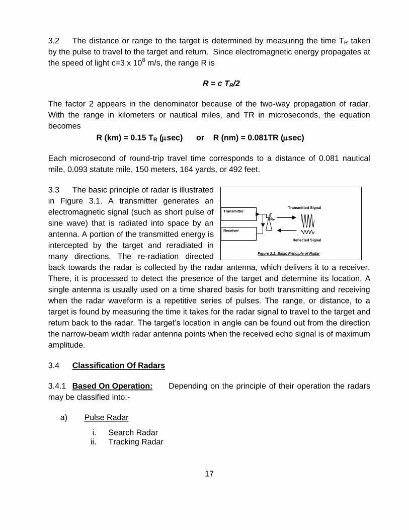
3.3 The basic principle of radar is illustrated
in Figure 3.1. A transmitter generates an
electromagnetic signal (such as short pulse of
sine wave) that is radiated into space by an
antenna. A portion of the transmitted energy is
intercepted by the target and reradiated in
many directions. The re-radiation directed
back towards the radar is collected by the radar antenna, which delivers it to a receiver.
There, it is processed to detect the presence of the target and determine its location. A
single antenna is usually used on a time shared basis for both transmitting and receiving
when the radar waveform is a repetitive series of pulses. The range, or distance, to a
target is found by measuring the time it takes for the radar signal to travel to the target and
return back to the radar. The target‘s location in angle can be found out from the direction
the narrow-beam width radar antenna points when the received echo signal is of maximum
amplitude.
3.4 Classification Of Radars
3.4.1 Based On Operation: Depending on the principle of their operation the radars
may be classified into:-
a) Pulse Radar
i. Search Radar ii. Tracking Radar
Transmitted Signal
Reflected Signal
Transmitter
Receiver
Figure 3.1: Basic Principle of Radar
18
b) CW Radar
i. CW Doppler Radar ii. FMCW Radar
c) Moving Target Indication Radar
i. MTI Radar ii. Pulse Doppler Radar
d) Array Radars
i. Phased array ii. Planar array
3.4.2 Based On Application: Radars in Navy may be classified based on their application
(a) Surveillance or Early Warning Radar
(b) Navigation Radar
(c) Gunnery Radar and tracking radar
3.5 Radar Frequencies
3.5.1 Conventional radars generally operate in what is called the microwave region (a
term not rigidly defined. Operational radars in the past have been at frequencies ranging
from about 100 MHz to 36 GHz, which covers more than eight octaves. These are not
necessarily the limits. Operational HF over the horizon of radar does operate at
frequencies as low as a few megahertz. At the other end of the spectrum, experimental
millimeter wave radars have been at frequencies higher than 240 GHz.
3.5.2 Initially, letter codes such as S, X and L were used to designate the distinct
frequency bands at which microwave radar was being developed. The original purpose
was to maintain military secrecy; but the letter designations were continued as convenient
shorthand means to readily denote the region of the spectrum at which radars operated.
The list of Radar frequency letter band designations approved by IEEE standard is given
in the table. These are related to the specific frequency allocations assigned by the
International Telecommunications Union (ITU) for radiolocation, or radar. For example, L
band officially extends from 1000 MHz to 2000 MHz, but L-band radar is only allowed to
operate within the region from 1215 to 1400 MHz since that is the band assigned by the
ITU.

19
3.5.3 List Of Radar Frequencies
(i) The Radar frequencies are classified as follows:
Band
Designation
Nominal Frequency
Range
Specific Frequency
Ranges for Radar
based on ITU
L 1 – 2 GHz 1215 – 1400 MHz
S 2 – 4 GHz 2300 – 2500 MHz 2700 – 3700 MHz
C 4 – 8 GHz 5250 – 5925 MHz
X 8 – 12 GHz 8500 – 10,680 MHz
Ku 12 – 18 GHz 13.4 – 14.0 GHz 15.7 – 17.7 GHz
(ii) The New Radar frequencies band has been introduced as below: -
Band Designation Nominal Frequency Range
A 0 – 250 MHz
B 250 – 500 MHz
C 500 – 1000 MHz
D 1 – 2 GHz
E 2 -3 GHz
F 3 – 4 GHz
G 4 – 6 GHz
H 6 – 8 GHz
I 8 – 10 GHz
J 10 – 20 GHz
K 20 – 40 GHz
L 40 – 60 GHz
M 60 – 100 GHz

20
3.6 Block Diagram For Pulse Radar The operation of pulse radar may be
described with the aid of the simple block diagram as shown in the figure 3.2. The Block
diagram may be divided into different sections namely Transmitter, Receiver, Display and
Antenna assembly. The functions of different blocks are covered in the succeeding
paragraphs
3.6.1 Transmitter The transmitter in radar generates High power pulses of short
duration that are fed to antenna through duplexer for transmission into free space. The
transmitter consists of mainly three units viz. Trigger Unit, Modulator and Oscillator.
(a) Trigger Unit: The trigger unit generates impulses of very short duration
which are used to trigger the modulator. The trigger is also applied to the display
which initiates the saw tooth generator through a multivibrator. The trigger unit is
also called as the Synchroniser. It is the main unit that synchronises all the sub
units of a radar system.
Duplexer
RF Amp
Mixer
IF Amp
2nd Detector Trigger/
Oscillator
Pulse Forming
Power Amp
VideoAmp
LO
Saw Tooth Generator
Multi-vibrator
Calibrator
Aerial Control
Unit Power
Supply Unit
TRA
NSM
ITTE
R
REC
EIV
ER
Figure 3.2Basic Block Diagram of Pulse Radar
21
(b) Modulator: The modulators main function is to turn the transmitter (High
Power Oscillator or Power Amplifier) on or off in synchronism with the trigger
pulses. In pulse radar, a modulator block decides the pulse width of the transmitted
pulse. In pulse radar the modulator is more specifically known as Pulse Modulator.
A modulator converts low power pulses of trigger unit into high power flat pulses
that are used to turn the transmitter on and off.
(c) Oscillator: The oscillator is a high power, high frequency oscillator, such as
magnetron. It is switched on and off by a modulator. A power amplifier is preferred
over an oscillator when high average power is necessary, when other than simple
pulse waveforms are required, or when good performance is needed in detecting
moving targets.
3.6.2 Antenna Assembly An Antenna assembly is considered as having two main
units namely Antenna and T/R Switch.
(a) T/R Switch: A transmit-receive switch controls the transmitting and receiving
operations, permitting the use of only one antenna for both transmitting and
receiving purposes and is more commonly known as Duplexer. During
transmission, it connects the transmitter to the antenna and isolates the sensitive
receiver from the damage due to high power transmitter pulses. In the interval
between the pulses, during which the reflected energy is being received, the
duplexer connects the antenna to the receiver. A T/R switch is generally located
near the transmitter unit, and not near the antenna.
(b) Antenna: Antenna is a device that matches the impedance of the EM waves
to the atmosphere. The antenna is used to radiate the EM waves from Oscillator or
power amplifier into the air. The same antenna is used to receive the reflected echo
of the target and feed it to the receiver.
3.6.3 Receiver The receiver is almost always a super heterodyne. This section of
radar does most of the signal processing on the received echo to identify the target to its
best. The receiver consist of various stages namely RF Amplifier, Mixer, IF amplifier, 2nd
Detector, Video amplifier and a local oscillator. The function of different modules in a
receiver follows in the succeeding paragraphs:
(a) RF Amplifier: The first stage of a super heterodyne receiver for radar
application can be a transistor amplifier. An RF stage is a low noise amplifier that
improves the weak signal received by the antenna. In some of the radar systems
(mostly older ones) this stage is seldom employed, instead the signal is directly fed

22
to the mixer stage. However, achieving a low noise amplifier is no longer the
problem it once was, and now almost all the modern radars include the first stage
as RF amplifier.
(b) Mixer: Whether or not it is used as the front-end, the mixer is a key element
in super heterodyne receiver. The mixer converts RF signal to IF signal. It receives
two inputs, one form RF amplifier and the other from Local Oscillator, and provides
a beat frequency of the two. The desired beat frequency is called the Intermediate
Frequency or more commonly as IF.
(c) Local Oscillator: A Reflex Klystron is usually used as a local oscillator in
radar system. It is a low power, high frequency oscillator. The local oscillator
frequency is made almost always higher (Why?) than the received RF.
(d) IF Amplifier: This stage is employed to amplify the weak IF signal from
mixer stage. It generally employs two or three stages to improve the echo level.
(e) 2nd Detector: The 2nd detector is used to detect the presence or absence of
the signal. It is called 2nd detector as the mixer is in fact the first detector stage.
(f) Video Amplifier: The video amplifier amplifies the detected signal and feeds
it to the Display.
(g) Indicator: Different types of Indicators are available for viewing various
parameters of the target through the received echo. Choice of display is one of the
important factors in design of Radar.
3.6.4 Display A display unit is an essential part in itself. It is a different technology in
itself. The Radar provides a video output which is further processed by Display system. It
consists of few supporting units to view the echo of the screen of a CRT. Modern displays
often employ LCD screen for Presentation of target echo. A display using CRT is assisted
by a Multivibrator that produces square or rectangular pulses, a Saw tooth generator to
produce the trace on the CRT screen and sometimes a calibrator to generate range rings
or range markers on the display. There are various other units used in the Display system
that assist in giving the best possible information from the received echo.
3.7 The different Radar parameters are defined as under:-
(a) Range to a Target The time for the signal to travel to a target located at a
range R and return back to the radar is 2R/c. The range to a target is then

23
cTR R = 2
With range in kilometers or in nautical miles, and T is microseconds, it becomes
R (km) = 0.15 TR (sec) or R (nmi) = 0.081 TR (sec) Therefore it follows that
(i) 150 meters = 164 yards = 492 feet = 0.081 nmi = 0.093 statute mile.
(ii) It takes 12.35 sec for radar Pulse to travel a nautical mile and back.
(b) Range Ambiguity: Once a signal is radiated into space by radar, sufficient
time must elapse to allow all echo signals to return to the radar before the next
pulse is transmitted. The rate at which pulses may be transmitted, therefore, is
determined by the longest range at which targets are expected. If the time between
pulses, say Tp, is too short, an echo signal from a long range target might arrive
after the transmission of the next pulse and be mistakenly associated with that
pulse (the next pulse) rather than the actual pulse transmitted earlier. This results in
Range Ambiguity i.e. doubtful range.
(c) Second time echoes: Echoes that arrive after the transmission of the next
pulse are called second-time-around echoes (or multiple-time-around echoes)
(d) Maximum Unambiguous Range: The range beyond which targets appear
as second-time-around echoes is the maximum unambiguous range, Runamb and
is given by:-
cTp c Runamb= =
2 2fp
(e) Pulse Length: In a Pulse Radar, the transmitter is switched ON and OFF
alternately to measure the range of a target. The time for which the Radar
Transmitter is kept ON is called the Pulse Length. It is specified in seconds
(f) Pulse Repetition Time: The time between two consecutive pulses is termed
as Pulse Repetition Time or simply PRT. It is measured in seconds
(g) Pulse Repetition frequency: The number of pulses transmitted in one
second is called as the Pulse Repetition Frequency or simply PRF. It is given in
Hertz(Hz)
(h) Peak Power: The peak amplitude of the transmitted pulse is called the peak
Power of the Radar. It is calculated in Watts.

24
(j) Average Power: The transmitter peak power averaged over the Pulse
Repetition Time (PRT). It is also measured in watts and can be calculated by
Peak Power (Pp) x Pulse Width (PW) Average Power (Pavg) =
Pulse Repetition Time (PRT) (k) Duty Cycle: The ratio of the total time the radar is radiating to the total time it could have radiated is termed as Duty Cycle. The duty cycle can be found by:
Pulse Length () OR x fp Duty Cycle =
Pulse Repetition Time (Tp)
Average Power (Pavg) OR Peak Power (Pp)
(l) Data Rate: Data Rate is the Hits per Scan.
(m) Antenna Rotation Rate: It is the number of rotation taken by Radar Antenna
in one second. It is declared in RPM.
(n) Echo: The reflected signal from the target is termed as the echo signal that
is processed by the radar receiver. It is given in Watts.
(p) Minimum Detectable Signal: It is the minimum power of the reflected signal
at which the radar is able to identify the presence of a target. It is given in watts.
(q) Frequency: Cycles per Second
(r) Range Resolution: It is the ability of Radar systems to separate
(distinguish) two targets whose distance from each other differs only slightly. If a
pulse of 1 sec is used this means that echoes returning from separate targets that
are 1sec apart in time (I.e. about 300 m in distance) will merge into one returned
pulse and will not be separated. It is seen that the range resolution is no better that
300 mtrs.
(s) Bearing Resolution: It is the ability of Radar systems to separate
(distinguish) two targets whose angular distance from each other differs only

25
slightly. That is the targets are at same distance but different bearing. It is also
called as the angular resolution and is dictated by the beamwidth of the antenna. IF
the beamwidth is 20, then two separate targets that are less than 20 apart will
appear as one target and will therefore not be resolved.
3.8 Factors Governing Pulse Characteristics
(a) Pulse Shape Requirement: An ideal radar pulse is expected to have
vertical sides and flat tops. The Leading edge of the transmitted pulse must be
vertical to ensure that the leading edge of the received pulse is also close to
vertical. Otherwise, ambiguity will exist as to the precise instant at which the pulse
has been returned, and therefore inaccuracies will creep into the exact
measurement of the target range. A flat top is required for the voltage pulse applied
to the magnetron anode; otherwise its frequency will be altered. It also is needed
because the efficiency of the magnetron, multicavity klystron or other amplifier
drops significantly if the supply voltage is reduced. A steep trailing edge is needed
for the transmitted pulse, so that the duplexer can switch the receiver over to the
antenna as soon as the body of the pulse has passed. It may sometime therefore
limit the minimum range of the radar.
(b) PRF Requirement: To achieve maximum unambiguous range the Radar
should not only be able to detect pulses returning from distant targets but also allow
them time to return before the next pulse is transmitted. However, this is also true
that the greater the number of pulses reflected from a target, the greater is the
probability of distinguishing this target from noise (Ambiguous range). Since the
antenna moves at a significant speed in many types of radar and yet it is necessary
to receive several pulses from a given target, a lower limit on the pulse repetition
frequency clearly exists.
(c) Pulse Width Requirement: If a short minimum Range (Dead Range) is
required, then short pulses must be transmitted. A shorter pulse also improves
range resolution. However, short pulses cannot travel longer distances and
moreover the receiver bandwidths must be increased as pulses are made narrower.
It is found that if is the pulse length in sec then the bulk of pulse energy is
contained in a frequency bandwidth of 2/MHz. Larger receiver bandwidth means
more noise. A longer pulse is therefore sometimes suitable though with a poor
range resolution. Further, for a pulse to travel a longer distance it needs larger
power. It may be achieved by increasing the peak pulse power, but only at the
expense of cost, size and power consumption. It is revealed that the maximum

26
range depends on the pulse energy rather than on its peak power. Therefore,
increase in range can be achieved by increasing the pulse width and thus
additionally resulting in reduction of receiver bandwidth. Briefly, a shorter pulse
length means good range resolution, good minimum range, less pulse power
however, shorter range and larger receiver bandwidth. Whereas, a longer pulse
length though have higher power requirement and poor range resolution/minimum
range it is advantageous for larger range and lower receiver bandwidth.
3.9 Factors influencing maximum range
(a) Effect of Transmitted power (Pt): The maximum range is proportional
to the fourth root of the peak transmitted pulse power. The peak power must be
increased sixteen fold, all else being constant, if a given maximum range is to be
doubled.
(b) Effect of Minimum Detectable Signal (Smin): An alternative to above is to
reduce the minimum detectable signal. This may make the receiver more
susceptible to jamming and interference, because it now relies more on its ability to
amplify weak signals (which could include the interference), and less on the sheer
power of the transmitted and received pulses.
(c) Effect of Antenna Aperture: It can be seen the radar range equation
that the maximum range is proportional to antenna diameter if the wavelength
remains constant. It is thus apparent that possible the most effective means of
doubling a given maximum range is to double the effective diameter of the antenna.
Alternatively, a reduction in the wavelength i.e. increase the frequency will also give
the same effect. But it is not as easy as it sounds. There is a limit here also, any
increase in diameter-to-wavelength ratio will reduce the beam width which may be
good for gunnery radar but is disadvantageous for a Surveillance or search radar.
(d) Effect of Target Area: The maximum radar range depends on the target
area as might be expected. However, this is not under the control of either the
designer, or maintainer or the user.
3.9 Some important terms used in Radar include:-
(a) Polarization. In the transmitted radar signal, the electric field is perpendicular to the direction of propagation, and this direction of the electric field is the polarization of the wave. Radars use horizontal, vertical, linear and circular polarization to detect different types of reflections. For example, circular polarization is used to minimize the interference caused by rain. Linear polarization returns

27
usually indicate metal surfaces. Random polarization returns usually indicate a fractal surface, such as rocks or soil, and are used by navigation radars. (b) Noise. Signal noise is an internal source of random variations in the signal, which is generated by all electronic components. Noise typically appears as random variations superimposed on the desired echo signal received in the radar receiver. The lower the power of the desired signal, the more difficult it is to discern it from the noise. Noise figure is a measure of the noise produced by a receiver compared to an ideal receiver, and this needs to be minimized. (c) Interference. Radar systems must overcome unwanted signals in order to focus only on the actual targets of interest. These unwanted signals may originate from internal and external sources, both passive and active. The ability of the radar system to overcome these unwanted signals defines its signal-to-noise ratio (SNR). SNR is defined as the ratio of a signal power to the noise power within the desired signal. (d) Clutter Clutter refers to radio frequency (RF) echoes returned from targets which are uninteresting to the radar operators. Such targets include natural objects such as ground, sea, precipitation (such as rain, snow or hail), sand storms, animals (especially birds), atmospheric turbulence, and other atmospheric effects, such as ionosphere reflections, meteor trails, and three body scatter spike. Clutter may also be returned from man-made objects such as buildings and, intentionally, by radar countermeasures such as chaff.Radar multipath echoes from a target cause ghosts to appear.Clutter may also originate from multipath echoes from valid targets caused by ground reflection, atmospheric ducting or ionospheric reflection/refraction (e.g. Anomalous propagation). (e) Jamming. Radar jamming refers to radio frequency signals originating from sources outside the radar, transmitting in the radar's frequency and thereby masking targets of interest. Jamming may be intentional, as with an electronic warfare tactic, or unintentional, as with friendly forces operating equipment that transmits using the same frequency range. Jamming is considered an active interference source, since it is initiated by elements outside the radar and in general unrelated to the radar signals.
3.10 Questions
3.10.1. List the bands and their frequency ranges commonly used in Radar.
3.10.2. What are the components required for design of a Radar.
3.10.3. Classify Radars on the basis of mode of operation and mode of application.
3.10.4. Explain the basic working of Radar with block diagram.

28
3.10.5. Define Duty Cycle, Average power and Peak power.
3.10.6. Explain Range and Bearing resolution.
3.10.7. What are the pulse requirements for better range resolution?
3.10.8. List down factors affecting maximum range of Radar.
3.10.9. What is noise and clutter?
3.10.10. How does polarization help improve Radar performance?
3.11 Suggested Reading
Introduction to Radar Systems – ML Skolnik Chapter 1 VP 132:- Basic Radar

29
CHAPTER-3
COMMUNICATION ENGINEERING 4.1 Introduction 4.1.1 The term Communications in a broad sense refers to the sending, receiving and processing of information by electronic means. The process started with wire telegraphy in the eighteen forties, developing with Telephony some decades later and Radio at the beginning of last century. Communication was made possible by the invention of the triode tube and was greatly improved in terms of technology, by the work done during World War II. Subsequently, it became even more widely used and refined through the invention and use of the transistor, integrated circuits and other semiconductor devices. More recently, the use of digital technology, including digital signal processing and computerized algorithms have made Communications even more widespread, with an increasing emphasis on computer and other data communications. The fall out of all these advancements in the Defence field has led the technology to the realm of ‗Network Centric Warfare‘, which has the communication as it backbone.
4.1.2 A modern Communications system is first concerned with the sorting, processing and sometimes storing of information before its transmission. The actual transmission then follows, with further processing and the filtering of noise. Finally we have reception, which may include processing steps such as decoding, storage and interpretation. 4.2. Communication System 4.2.1. A communication system can be divided into three broad categories: transmitting equipment, receiving equipment, and terminal equipment. Transmitting equipment generates, amplifies, and modulates a transmitted signal. Receiving equipment receives a radio wave, then amplifies and demodulates it to extract the original intelligence. Terminal equipment is used primarily to convert the audio signals of encoded or data transmission into the original intelligence. The transmitting equipment creates a radio-frequency (RF) carrier and modulates it with audio intelligence to produce an RF signal. This RF signal is amplified and fed to the transmitting antenna, which converts it to electromagnetic energy for propagation. The receiving antenna converts the portion of the electromagnetic wave it receives into a flow of alternating RF currents. The receiver then converts these currents into the intelligence that was contained in the transmission. Terminal equipment is used primarily where coded transmissions are employed, to convert the modulated signal into the original intelligence. Figure 4.1 represents basic communication equipment.
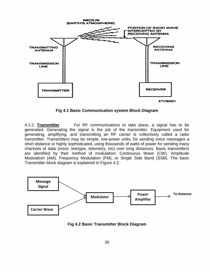
30
Fig 4.1 Basic Communication system Block Diagram
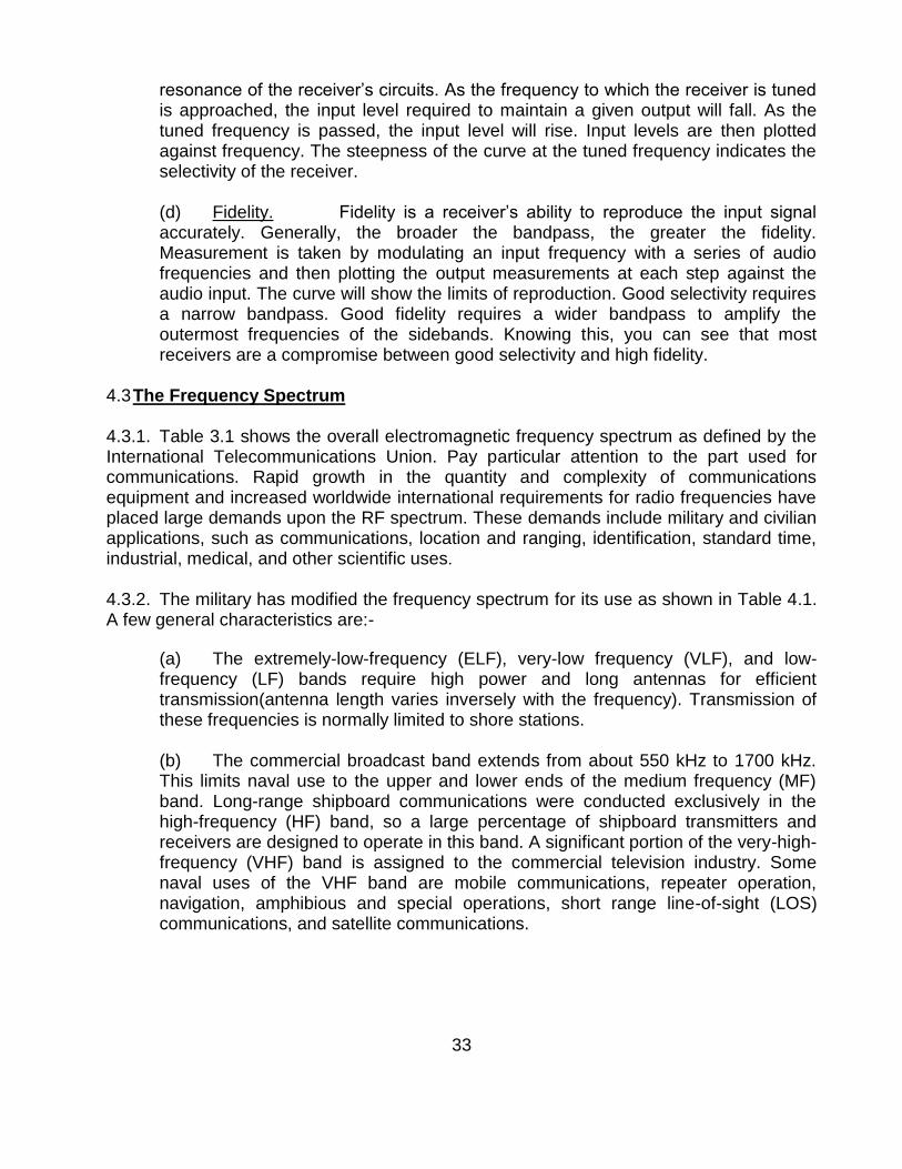
4.2.2. Transmitter For RF communications to take place, a signal has to be generated. Generating the signal is the job of the transmitter. Equipment used for generating, amplifying, and transmitting an RF carrier is collectively called a radio transmitter. Transmitters may be simple, low-power units, for sending voice messages a short distance or highly sophisticated, using thousands of watts of power for sending many channels of data (voice, teletype, telemetry, etc) over long distances. Basic transmitters are identified by their method of modulation: Continuous Wave (CW), Amplitude Modulation (AM), Frequency Modulation (FM), or Single Side Band (SSB). The basic Transmitter block diagram is explained in Figure 4.2.
Fig 4.2 Basic Transmitter Block Diagram
Carrier Wave
Message Signal
Modulator Power
Amplifier
To Antenna

31
4.2.3. Receiver
4.2.3.1. A receiver processes modulated signals and delivers, as an output, a reproduction of the original intelligence. The signal can then be applied to a reproducing device, such as a loudspeaker or a teletypewriter. To be useful, a receiver must perform certain basic functions. These functions are reception, selection, detection, and reproduction. Reception occurs when a transmitted electromagnetic wave passes through the receiver antenna and induces a voltage in the antenna. Selection is the ability to distinguish a particular station‘s frequency from all other station frequencies appearing at the antenna. Detection is the extraction of the modulation from an RF signal. Circuits that perform this function are called detectors. Different forms of modulation require different detector circuits. Reproduction is the action of converting the electrical signals to sound waves that can be interpreted by the ear. The basic Superhetrodyne receiver is explained in Figure 4.3.
Fig 4.3 Basic SuperhetrodyneReceiver
4.2.3.2 The reasons for use of superheterodyne receiver is that the received frequency will be the same as transmitted frequency and therefore would be of a higher range in the order of hundreds of MHz or GHz. Signal processing and demodulation is extremely complicated at such high frequencies since it is cumbersome to design the electronics with clock synchronisation at such high frequencies. The superheterodyne receiver ensures down-conversion of received frequencies so as to enable easy signal processing and filtering process at nominal Intermediate frequency.One problem, which has to be contended within the superheterodyne receiver, is its ability to
Remember: Image Frequency is the frequency available at Mixer input arising due to combination of harmonics of LO and received frequencies. This image frequency gives rise to distortion in IF stage signal processing since it will have spurious amplitudes in IF frequency range.

32
pick up a second or imagefrequency removed from the signal frequency by a value equal to twice the IF. To illustrate the point, refer Figure 4.4. In this example, we have a signal frequency of 1 MHz which mix to produce an IFof455kHz. A second or image signal, with a frequency equal to 1 MHz plus (2 x 455) kHz or 1.910 MHz, can also mix with the 1.455 MHz to produce the 455 kHz. Reception of an image signal is obviously undesirable and a function of the RF tuned circuits (ahead of the mixer), is to provide sufficient selectivity to reduce the image sensitivity of the receiver to tolerable levels.
Figure 4.4 An illustration of how image frequency provides a second mixing product.
4.2.3.3 Receiver Characteristics Understandingreceiver characteristics are mandatory in determining operational condition and for comparing receivers. Important receiver characteristics are sensitivity, noise, selectivity, and fidelity.
(a) Sensitivity. Sensitivity is a measure of receiver‘s ability to reproduce very weak signals. The weaker the signal that can be applied and still produce a certain signal-to-noise (S/N) ratio, the better that receiver‘s sensitivity rating. Usually, sensitivity is specified as the signal strength in microvolts necessary to cause a S/N ratio of 10 dB. (b) Noise. All receivers generate noise. Noise is the limiting factor on the minimum usable signal that the receiver can process and still produce a usable output. Expressed in decibels, it is an indication of the degree to which a circuit deviates from the ideal; a noise figure of 0 decibels is ideal. (c) Selectivity. Selectivity is the ability of a receiver to distinguish between a signal at the desired frequency and signals at adjacent frequencies. The better the receiver‘s ability to exclude unwanted signals, the better its selectivity. The degree of selectivity is determined by the sharpness of resonance to which the frequency determining components (bandpass filters) have been engineered and tuned. Measurement of selectivity is usually done by taking a series of sensitivity readings in which the input signal is stepped along a band of frequencies above and below
33
resonance of the receiver‘s circuits. As the frequency to which the receiver is tuned is approached, the input level required to maintain a given output will fall. As the tuned frequency is passed, the input level will rise. Input levels are then plotted against frequency. The steepness of the curve at the tuned frequency indicates the selectivity of the receiver. (d) Fidelity. Fidelity is a receiver‘s ability to reproduce the input signal accurately. Generally, the broader the bandpass, the greater the fidelity. Measurement is taken by modulating an input frequency with a series of audio frequencies and then plotting the output measurements at each step against the audio input. The curve will show the limits of reproduction. Good selectivity requires a narrow bandpass. Good fidelity requires a wider bandpass to amplify the outermost frequencies of the sidebands. Knowing this, you can see that most receivers are a compromise between good selectivity and high fidelity.
4.3 The Frequency Spectrum 4.3.1. Table 3.1 shows the overall electromagnetic frequency spectrum as defined by the International Telecommunications Union. Pay particular attention to the part used for communications. Rapid growth in the quantity and complexity of communications equipment and increased worldwide international requirements for radio frequencies have placed large demands upon the RF spectrum. These demands include military and civilian applications, such as communications, location and ranging, identification, standard time, industrial, medical, and other scientific uses.
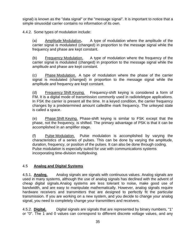
4.3.2. The military has modified the frequency spectrum for its use as shown in Table 4.1. A few general characteristics are:-
(a) The extremely-low-frequency (ELF), very-low frequency (VLF), and low-frequency (LF) bands require high power and long antennas for efficient transmission(antenna length varies inversely with the frequency). Transmission of these frequencies is normally limited to shore stations. (b) The commercial broadcast band extends from about 550 kHz to 1700 kHz. This limits naval use to the upper and lower ends of the medium frequency (MF) band. Long-range shipboard communications were conducted exclusively in the high-frequency (HF) band, so a large percentage of shipboard transmitters and receivers are designed to operate in this band. A significant portion of the very-high-frequency (VHF) band is assigned to the commercial television industry. Some naval uses of the VHF band are mobile communications, repeater operation, navigation, amphibious and special operations, short range line-of-sight (LOS) communications, and satellite communications.
34
Table 4.1 Frequency Bands (c) The ultra-high-frequency (UHF) band is used extensively by the Navy for LOS and satellite communications. Mobile communications, radar (over 400 MHz), and special operations are some other uses. (d) The super-high-frequency (SHF) band is the workhorse of microwave communications. LOS communications, terrestrial, and satellite relay links, radar, and special operations are some other uses. Experimental use of the extremely-high frequency (EHF) band is ending. The Fleet Satellite (FLTSAT) EHF Package (FEP) is attached to two modified uhf FLTSATs. The FEP is currently providing ehf communications capability to Army, Navy, and Air Force ground, airborne, and oceangoing terminals.
4.4 Modulation
4.4.1. Modulation is a process of mixing a signal with a sinusoid to produce a new signal. This new signal, conceivably, will have certain benefits over an un-modulated signal, especially during transmission. If we look at a general function for a sinusoid f(t) = ASin(ωt + φ), we can see that this sinusoid has three parameters that can be altered, to affect the shape of the graph. A is the magnitude, or amplitude of the sinusoid; ω is the frequency, and φ is the phase angle. All these parameters can be altered to transmit data. The sinusoidal signal that is used in the modulation is known as the carrier signal, or simply "the carrier". The signal that is used in modulating the carrier signal (or sinusoidal
35
signal) is known as the "data signal" or the "message signal". It is important to notice that a simple sinusoidal carrier contains no information of its own. 4.4.2. Some types of modulation include:
(a) Amplitude Modulation. A type of modulation where the amplitude of the carrier signal is modulated (changed) in proportion to the message signal while the frequency and phase are kept constant. (b) Frequency Modulation. A type of modulation where the frequency of the carrier signal is modulated (changed) in proportion to the message signal while the amplitude and phase are kept constant. (c) Phase Modulation. A type of modulation where the phase of the carrier signal is modulated (changed) in proportion to the message signal while the amplitude and frequency are kept constant. (d) Frequency Shift Keying. Frequency-shift keying is considered a form of FM. It is a digital mode of transmission commonly used in radioteletype applications. In FSK the carrier is present all the time. In a keyed condition, the carrier frequency changes by a predetermined amount calledthe mark frequency. The unkeyed state is called a space. (e) Phase Shift Keying. Phase-shift keying is similar to FSK except that the phase, not the frequency, is shifted. The primary advantage of PSK is that it can be accomplished in an amplifier stage. (f) Pulse Modulation. Pulse modulation is accomplished by varying the characteristics of a series of pulses. This can be done by varying the amplitude, duration, frequency, or position of the pulses. It can also be done through coding. Pulse modulation is especially suited for use with communications systems incorporating time-division multiplexing.
4.5 Analog and Digital Systems 4.5.1. Analog. Analog signals are signals with continuous values. Analog signals are used in many systems, although the use of analog signals has declined with the advent of cheap digital signals.Analog systems are less tolerant to noise, make good use of bandwidth, and are easy to manipulate mathematically. However, analog signals require hardware receivers and transmitters that are designed to perfectly fit the particular transmission. If you are working on a new system, and you decide to change your analog signal, you need to completely change your transmitters and receivers. 4.5.2. Digital. Digital signals are signals that are represented by binary numbers, "1" or "0". The 1 and 0 values can correspond to different discrete voltage values, and any

36
signal that doesn‘t quite fit into the scheme just gets rounded off. Digital signals are more tolerant to noise, but digital signals can be completely corrupted in the presence of excess noise. In digital signals, noise could cause a 1 to be interpreted as a 0 and vice versa, which makes the received data different than the original data. Imagine if the army transmitted a position coordinate to a missile digitally, and a single bit was received in error. This single bit error could cause a missile to miss its target by miles. Luckily, there are systems in place to prevent this sort of scenario, such as checksums and Cyclic Redundancy Checks, which tell the receiver when a bit has been corrupted and ask the transmitter to resend the data. The primary benefit of digital signals is that they can be handled by simple, standardized receivers and transmitters, and the signal can be then dealt with in software (which is comparatively cheap to change). 4.6 Noise. In communication systems, the noise is an error or undesired random disturbance of a useful information signal, introduced before or after the detector and decoder. The noise is a summation of unwanted or disturbing energy from natural and sometimes man-made sources. There are various types of noises, viz., Thermal noise, Shot noise, Flicker noise, Burst noise etc. 4.7. Basic Antenna Theory
4.7.1. Radio waves are generated by electrons accelerating in the antenna. Consider a transmitter perpendicular to the ground. The electrons in the antenna, when a signal is applied, are changing their velocities continuously (i.e. moving up and down very quickly) in response to the applied signal
4.7.1 Dipole Antenna:-A dipole antenna is a radioantenna that can be made of a simple wire, with a center-fed driven element. It consists of two metal conductors of rod or wire, oriented parallel and collinear with each other (in line with each other), with a small space between them. The radio frequency voltage is applied to the antenna at the center, between the two conductors. These antennas are the simplest practical antennas from a theoretical point of view. They are used alone as antennas, notably in traditional "rabbit ears" television antennas, and as the driven elementin many other types of antennas, such as the Yagi.
Fig 4.5 Half Wave Dipole and Yagi-uda antenna

37
4.7.2. There is only one part of a receiving aerial that is active, i.e. does the receiving and is connected to the TV/radio set. This active element is called the dipole. The simplest design of antenna would consist of a dipole only. Figure 4.6 shows the radiation pattern of a half-wave dipole.We can change the directivity of the aerial by adding other elements. Any other elements that we add to the basic half-wave dipole are called passive elements and are not connected electrically to the dipole.
Fig 4.6 Radiation pattern of antenna
4.7.3. Monopole Antenna A monopole antenna is a class of radio antenna consisting of a straight rod-shaped conductor, often mounted perpendicularly over some type of conductive surface, called a ground plane. The driving signal from the transmitter is applied, or for receiving antennas the output voltage is taken, between the lower end of the monopole and the ground plane. One side of the antenna feedline is attached to the lower end of the monopole, and the other side is attached to the ground plane, which is often the Earth. This contrasts with a dipole antenna which consists of two identical rod conductors, with the signal from the transmitter applied between the two halves of the antenna. Common types of monopole antenna are the whip, rubber ducky, helical, random wire, mast radiator, and ground plane antennas.Like a dipole antenna, a monopole has an omni-directionalradiation pattern. That is it radiates equal power in all azimuthal directions perpendicular to the antenna, but the radiated power varies with elevation angle, with the radiation dropping off to zero at the zenith, on the antenna axis.A monopole can be visualized as being formed by replacing one half of a dipole antenna with a ground plane at right-angles to the remaining half. If the ground plane is large enough, the radio waves reflected from the ground plane will seem to come from an image antenna forming the missing half of the dipole, which adds to the direct radiation to form a dipole radiation pattern. So the pattern of a monopole with a perfectly conducting, infinite ground plane is identical to the top half of a dipole pattern, with its maximum radiation in the horizontal direction, perpendicular to the antenna

38
Fig 4.7 Monopole antenna and its equivalent
4.8. Fiber Optics 4.8.1. Fiber-Optic Communication is a method of transmitting information from one place to another by sending pulses of light through an optical fiber. The light forms an electromagnetic carrier wave that is modulated to carry information. The process of communicating using fiber-optics involves the following basic steps: Creating the optical signal involving the use of a transmitter, relaying the signal along the fiber, ensuring that the signal does not become too distorted or weak, receiving the optical signal, and converting it into an electrical signal. 4.8.2. An optical fiber is a flexible, transparent fiber made of very pure glass (silica) not much wider than a human hair that acts as a waveguide, or "light pipe", to transmit light between the two ends of the fiber.Fibers are used instead of metal wires because signals travel along them with less loss and are also immune to electromagnetic interference.
Fig 4.8 Fiber optic transmission
4.8.3. Optical fiber typically consists of a transparent core surrounded by a transparent cladding material with a lower index of refraction. Light is kept in the core by total internal reflection. This causes the fiber to act as a waveguide.
39
4.9. Questions 4.9.1 What is the requirement for modulation? 4.9.2 What are the various RF frequency bands and there applications? 4.9.3 What do you mean by ground waves and sky waves and what are the atmospheric
effects on the propagation of sky waves? 4.9.4 How does an antenna radiate/function? Where the feed horn of an antenna should
be kept in order to obtain a parallel beam? Relate this theory to optical mirrors/ lenses.
4.9.5 List down the various types of digital modulation schemes. 4.9.6 What are the various atmospheric phenomena that affect propagation of radio
waves? 4.9.7 What are the receiver characteristics which need to be taken care of while
designing a communication system? 4.9.8 What is the difference between analog, digital and discrete signals? 4.9.9 Why are optical fibers used to transmit for long distance communication? 4.9.10 What are the uses and disadvantages of Superhetrodynereceivers.
4.10 Suggested Reading Electronic Communication Systems – Kennedy Chapter 1 Chapter 2 VP 206:- Communication Systems

40
CHAPTER-4
INSTRUMENTATION AND TEST EQUIPMENT
6.1 Introduction
6.1.1 Maintenance and repair of various electrical equipment involves use of test equipment. Proper use of these test equipment reduces time of repair/maintenance, resulting reduced system down time. Knowledge of using test equipment is enhanced by regular use of these test equipment. Mastering on electrical equipment can only be achieved by mastering on the required test equipment.
6.1.2 Electronic measurements involve the fundamental electrical quantities of voltage and current and the inherent characteristics of resistance, capacitance, and inductance. In circuits being tested, voltage and current are dependent upon resistance, capacitance, and inductance for their distribution; therefore, voltage and current measurements are valuable aids in determining circuit component conditions and in the evaluation of symptoms. Practically any reading obtained from the use of test equipment will depend on these basic measured quantities of resistance, capacitance, and inductance.
6.2 Various Instruments and Test Equipment
6.2.1 Digital Multimeter
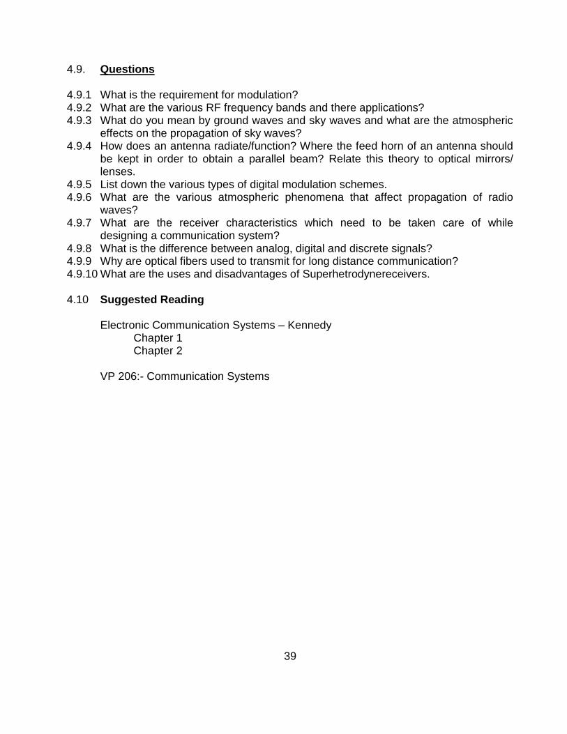
The Digital Multimeter (DMM) displays measurement of DC and AC voltages as discrete numerals instead of a pointer deflection on a continuous scale. It is also used for measuring the continuity of wire or a circuit. Numerical readout is advantageous in many applications because it reduces human reading and interpolation errors, eliminates parallax error, increases reading speed and provides output in digital form which is suitable for further processing or recording.
41
Fig 6.2.1Digital Multimeter
6.2.1.1 Operation of Digital Multi Meter
(a) Voltage Measurement. Select the appropriate function DC or AC and the voltage button, V. Now select the required range on the rotary range switch. Apply the input to the sockets labelled (+) and (-). It is advisable, where possible, to connect the low input to the lowest impedance with respect to ground. This will reduce common mode voltages. To measure a voltage above 1 KV, the HV probe is availed. For RF voltage measurement use the probe with the BNC to 4mm adaptor.
(b) Current Measurement. Select the appropriate function, DC or AC along with the current button. Now select the required range on the rotary range switch. Apply the input to the (+) and (-) sockets for ranges up to 2 Amp. For the 10 Amp range, connect the high input to the separate 10 Amps terminal. The maximum continuous overload is 2 Amp and the fuse, provides protection for sustained overloads in case of excess current. The 10 Amps range is not protected.
(c) Resistance Measurement. Select the function button to ohms and the appropriate range with the rotary range switch. Connect the resistance to be measured between the (+) & (-) socket. The internal current sources for measurement, give a negative voltage at the (+) socket. The input is protected up to 250 V rms on all ranges.
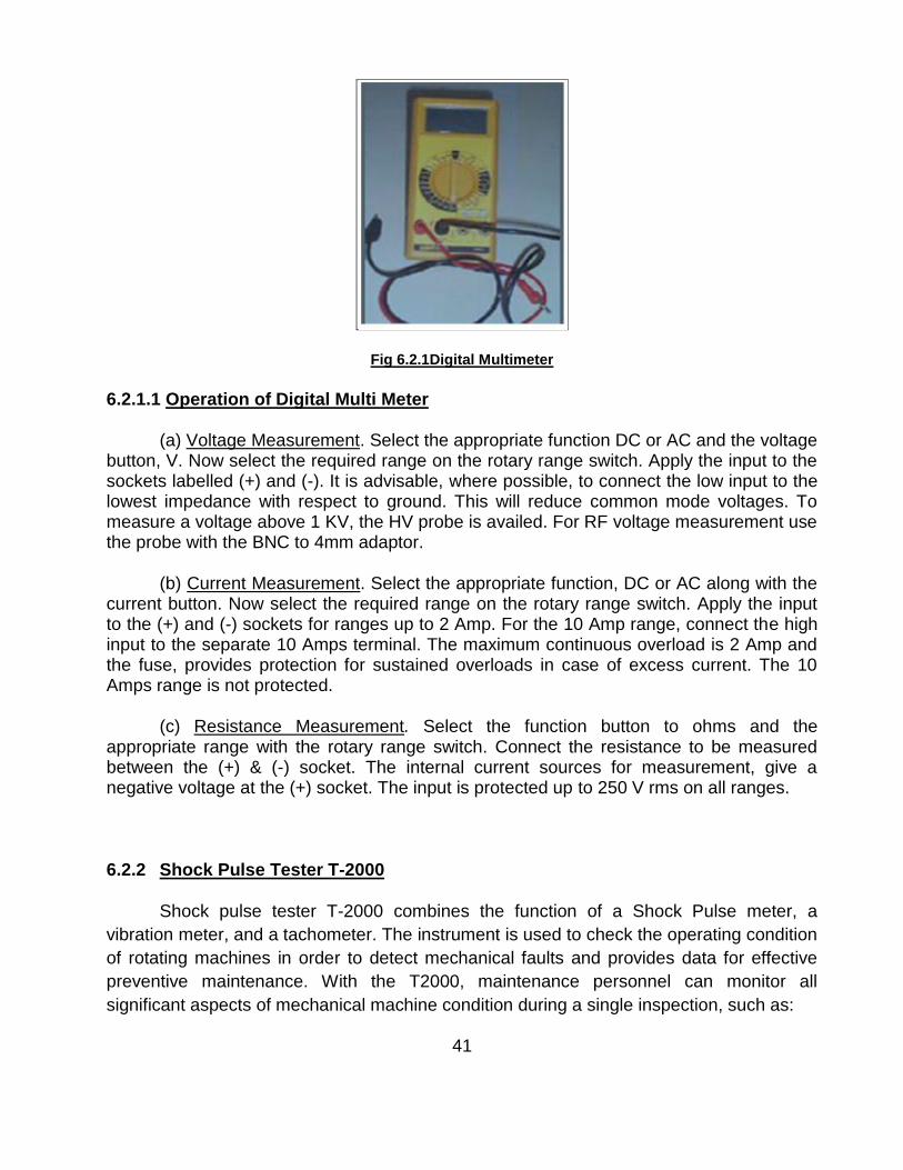
6.2.2 Shock Pulse Tester T-2000
Shock pulse tester T-2000 combines the function of a Shock Pulse meter, a
vibration meter, and a tachometer. The instrument is used to check the operating condition
of rotating machines in order to detect mechanical faults and provides data for effective
preventive maintenance. With the T2000, maintenance personnel can monitor all
significant aspects of mechanical machine condition during a single inspection, such as:

42
(a) The mechanical condition of rolling bearings (bearing damage development).
(b) General machine condition (the effect of structural looseness, misalignment and
out-of-balance on machine vibration).
Fig 6.2.2 Shock pulse tester
6.2.3 Electrical Motor Checker EMC-22
6.2.3.1 Introduction EMC-22 provides a fast and easy means to detect electrical faults-short circuits, open circuits, damaged insulation etc, in motor and other three phase machines. EMC-22 is used on stationary motors. The motor has to be isolated from its power supply before testing. There is no need to disconnect the supply cable, provided the power is switched off. Readings can be taken at any point along the motor power supply. The basic test can be made on site without disconnecting the phase windings.
6.2.3.2 The Basic Test. On any three-phase machines, an electrical fault can be detected in the following manner:-
(a) Measuring insulation resistance to earth.
(b) Measuring and comparing the resistance of different phases of stator winding.
(c) Measuring and comparing the inductance of different phases of stator winding.

43
Fig 6.2.3.2 EMC-22
6.2.3.3 Resistance and inductance values of each phase are measured and compared
with each other. They should be equal or any difference between the values should be
within acceptable tolerance limits. Measurements should be made in the above sequence.
The sequence can be interrupted as soon as fault is detected.
6.2.4 Tong Tester
6.2.4.1 Introduction This instrument is used to measure current. Two basic versions
which are available are for D.C. and the other for A.C measurement. The advantage of this
instrument over other current measuring devices such as an AVO is that there is no
requirement to break a circuit, to introduce the meter in series for the measurement. It is
however less accurate. It is ideal for measuring the current in damage control cables and
current drawn by motors, large transformers, etc.
Fig 6.2.4.1 Tong tester
6.2.4.2 Operating Procedure Clip ON ammeter around each cable in turn and measure
current. Select the highest scale reading initially to prevent damage to needle
6.2.5 Neon Tester
6.2.5.1 Introduction Neon Tester (N.T) is small and handy test equipment which is used
to check whether the circuit is alive or dead. It is used to measure an approximate AC and
DC voltage between 110 V and 700 V. It is also used to check whether three phase supply
is available in the supply cables. A picture of a neon tester is shown below.

44
Fig 6.2.5.1 Neon tester
6.2.5.2 Description This instrument consists of two, rubber hand assemblies with PVC
insulated brass probes. One hand assembly incorporates a NEON LAMP and a solenoid,
which can be actuated by AC or DC supply (red scale for DC and yellow scale for AC). To
check the voltage, the switch (ring push button which is housed within the PVC insulated
probe) must be pressed. When measuring AC voltages the frequency should be 60 Hz.
Other frequencies will give inaccurate reading on scale.
6.2.5.3 Use of Neon Lamp The neon lamp is used to indicate the voltage and polarity. If
an AC voltage is measured the neon will burn over its full length. If it is used on DC it will
burn at one end only.
6.2.6 Strobo Scope
6.2.6.1 Introduction Stroboscope is test equipment, which is used to measure r.p.m of the
running machinery. The equipment has a flashing lamp whose frequency can be varied.
When the flashing frequency of stroboscope is synchronised with running machinery‘s
r.p.m, the r.p.m is displayed on the seven-segment display available on the stroboscope.
Fig 6.2.6.1 Stroboscope

45
6.2.7 Megger
6.2.7.1 Introduction Wee Megger is a type of self contained high generator, used to find
the high resistance and insulation of the equipment. When very high resistance is to be
measured the current produced with batteries are too small to be measured. It is therefore
necessary to use much higher voltage. Another reason for using high voltage is to check
the breakdown of insulation of cable.
6.2.7.2 Operation
(a) Connect the load across Megger connections and rotate the hand wheel i.e.
+ve terminal to inner conductor and -ve terminal to ground.
(b) The scale should not show zero. It should be in mega ohms. e.g. for good
insulation it must read more than 100 m ohm.
(c) Testing capacitor:- Connect the capacitor under test to Megger. Rotate the
hand wheel. If capacitor is charging, needle will start showing increasing resistance which
means capacitor is good. If meter is steady, the capacitor is bad (not getting charged).
(d) Testing insulation:- Connect the load across Megger connections and rotate
the hand wheel i.e. +ve terminal to inner conductor and -ve terminal to ground.
The scale should not show zero. It should be in mega ohms. e.g. for good insulation it
must read more than 100 m ohm.
Fig 6.2.7.1 Wee Megger
6.2.8 Spectrum Analyser

46
6.2.8.1 Introduction Spectrum analysis is defined as the study of energy distribution
across the frequency spectrum of a given electrical signal. The study gives valuable
information about bandwidth, effects of different types of modulation and spurious signal
generation. The knowledge of the above quantities and phenomena are useful in the
design and testing of radio frequency (RF) and pulse circuitry.
Fig 6.2.7.1 Spectrum Analyser
6.2.8.2 Spectrum analysis is divided into two major categories on account of
instrumentation limitations and capabilities. These are:-
(a) Audio frequency (AF) analysis
(b) Radio frequency (RF) spectrum analysis
RF spectrum analysis covers a frequency range of 10 MHz to 40 GHz, and hence is more important, because it includes majority of communication, navigation, radar, and industrial instrumentation frequency bands. Spectrum analyzers are sophisticated instruments which are capable of portraying graphically, amplitude of the signal as a function of frequency. These instruments find wide applications for measurement of attenuation, FM deviation and frequency.
6.2.9 Digital Oscilloscope
6.2.9.1 Introduction The oscilloscope is probably the most versatile tool for the
development of modern electronic circuits and systems. This device allows the amplitude
of electrical signal, such as voltage, current, power etc. to be displayed primarily as a
function of time. The oscilloscope depends on the movement of an electron beam, which
is then made visible by allowing the beam to impinge on a phosphor surface, which
produces a visible spot. A view of Digital Oscilloscope TDS 220 from Tektronix is
shown below and is discussed subsequently.

47
Fig 6.2.8.1 Digital Oscilloscope
6.2.9.2 Function of oscilloscope. The oscilloscope is used to find out the following:-
(a) The amplitude of the signal (Voltage AC/DC)
(b) Frequency of the signal
(c) Phase difference of two signals
(d) Wave form analysis or pulse measurement of quantities such as :-
(i) Rise time of the pulse
(ii) Fall time of the pulse
(iii) Over rising of pulse
(iv) Pulse width
6.2.10 Signal Generator
6.2.10.1 Introduction The signal generator is used to provide known test conditions for the performance evaluation of various electronic systems and for replacing missing signals in systems which are being analyzed for repairs. The standard signal generator is a source of sine wave voltage with an appreciable range of frequency and amplitude both of which are known to a high degree of accuracy. The instrument is provided with means of modulating the carrier frequency which is indicated by the dial setting. The modulation is indicated by a meter. Modulation may be sine wave, square wave and triangular wave. The output signal may be amplitude modulated (AM) or frequency modulated (FM). Usually amplitude modulation is employed.

48
Fig 6.2.9.1Signal generator
6.2.11 Time and Frequency Counter
6.2.11.1 Introduction The time and frequency counter is used to measure the frequency
generated from an oscillator/sine-wave generator. The signal whose frequency is to be
measured is fed to the frequency counter. The counter measures the signal and displays
on LCD display.
Fig 6.2.10.1 Time and Frequency Counter
6.2.10.2 Principle of Operation The signal whose frequency is to be measured is divided
into a train of pulses with duration of one cycle for the signal. Thereafter, the number of
pulses which are applied in a definite interval of time are counted by means of electronic
counter. Since the pulse represents the cycle of unknown signal, the number appearing on
the counter is a direct indication of the frequency of the unknown signal.

49
6.3 Questions
6.3.1 What do you understand by CRETE? Which all test equipment come under
CRETE?
6.3.2 What all precautions must be taken when measuring the insulation of a motor?
6.3.3 Where will you find the bearing diameter before entering the value into shock pulse
tester?
6.3.4 What is the basic principle behind Tong Tester?
6.3.5 What all precautions must be taken when using Megger?
6.3.6 What device sweeps a band of frequencies to determine frequencies and amplitudes of each frequency component?
6.3.7 Name two instruments used to analyze waveforms?
6.3.8 How do you measure the continuity of a wire or circuit and which test equipment will you use?
6.4 Suggested Reading
VP 204:- Instrumentation and controls
VP 191:- Common Test Equipment