pre engineered building
DESCRIPTION
Steel structuresTRANSCRIPT
1
CHAPTER 1
INTRODUCTION
1.1 GENERAL
Buildings & houses are one of the oldest construction activities of human beings the
construction technology has the beginning from primitive construction technology to
the present concept of modern house building. The present construction methodology
for buildings calls for the best aesthetic look, high quality & fast construction, cost
effective & innovative touch.
1.2 PEB IN INDIA
India has the second fastest growing economy in the world and a lot of it, is attributed
to its construction industry which figures just next to agriculture in its economic
contribution to the nation. In its steadfast development, the construction industry has
discovered, invented and developed a number of technologies, systems and products,
one of them being the concept of Pre-engineered Buildings (PEB s). As opposed to
being on-site fabricated, PEB s are delivered as a complete finished product to the site
from a single supplier with a basic structural steel framework with attached factory
finished cladding and roofing components. The structure is erected on the site by bolting
the various building components together as per specifications. PEB s are developed
using potential design software. The onset of technological advancement enabling 3d
modelling and detailing of the proposed structure and coordination has revolutionized
Conventional building construction. Pre-Engineered
PEB has boon to Multi storey Buildings in India. Decking sheets with concrete over can
be used as roofing and raised to any extent above 40 meters. These have a tracking rate
of 80% in western countries. PEB Buildings is the future for India. Most of the Indian

2
business community is just started to realize the benefits of PEB .Where you have been
building with concrete for as long as anyone can remember, it is difficult to change.
However India’s most progressive companies are seeing the benefits of PEB
Although PEB systems are extensively used in industrial and many other non–
residential constructions worldwide it is relatively a new concept in India .these concept
were introduced to the Indian markets lately in the late 1990’s with the opening up of
the economy and a number of multi nationals setting up their projects .the market
potential of PEB is 1.2 million tonnes per annum .the current pre – engineered steel
building manufacturing capacity is 0.35 tonnes per annum. The industry is growing at
the compound rate of 25 to 35 % [16]
1.3 SCOPE AND OBJECTIVES OF THE PROJECT
1.3.1 SCOPE OF THE PROJECT
1. Steel buildings in which excess steel is avoided by tapering the sections which in
turn is more economical and aesthetic than conventional steel building
2. Tapering is done as per Bending Moment requirements as to avoid excess of steel.
3. Components are manufactured in factory and assembled on site.
4. Larger plate dimensions are used in areas of higher load effects in case of large
spans and high rise industrial building such as aircraft hangars, warehouse etc.
5. An efficiently designed Pre-Engineered Building can be lighter that the
conventional steel buildings by up to 30% and thus economical
PEB concept has been very successful and well established in North America, Australia
and is presently expanding in U.K and European countries. PEB construction is 30 to
3
40% faster than masonry construction. PEB buildings provide good insulation effect
and would be highly suitable for a tropical country like India.
The pre-engineered building calls for very fast construction of buildings and with good
aesthetic looks and quality construction. Pre-engineered Buildings can be used
extensively for construction of industrial and residential buildings.
1.3.2 OBJECTIVE OF THE PROJECT
The following are objective of the project and a detailed report on design and analysis
of the pre-engineered building is discussed in the upcoming chapters.
1. To Study Pre-Engineered Building.
2. To Prepare a Model of P.E.B.
3. To Analyze Structure Using STAAD Pro.
4. To Design Sections, Connections etc.
5. To Study The Effect Of P.E.B. For Following Issues:
i. To Reduce Complexity On Site.
ii. To Achieve Accuracy.
iii. Speed of Work.

4
CHAPTER 2
LITERATURE REVIEW
2.1 GENERAL
In this chapter the literature review of pre-engineered building is carried out from
various books, reference, journals, and from several websites .the brief discussion of
the pre-engineered building is presented below in this project
2.1.1 Syed Firoz, Sarath,Chandra Kumar et.al (2012) observed that, The pre-
engineered steel building system construction has great advantages to the single storey
buildings, practical and efficient alternative to conventional buildings, the System
representing one central model within multiple disciplines. Pre- engineered building
creates and maintains in real time multidimensional, data rich views through a project
support is currently being implemented by STAAD pro software packages for design
and engineering [16]. Choosing steel to design a Pre-engineered steel structures
building is to choose a material which offers low cost, strength, durability, design
flexibility, adaptability and recyclability. Steel is the basic material that is used in the
Materials that are used for Pre- engineered steel building. It negates from regional
sources. It also means choosing reliable industrial products which come in a huge range
of shapes and colours; it means rapid site installation and less energy consumption. It
means choosing to commit to the principles of sustainability. Infinitely recyclable, steel
is the material that reflects the imperatives of sustainable development.
A tall steel building is not more in the total number of tall steel structures that are built
around the world. A large steel structures being built are only single storey buildings
for industrial purpose. Secondary structural members span the distance between the
primary building frames of metal building systems. They play a complex role that
extends beyond supporting roof and wall covering and carrying exterior loads to main

5
frames. Secondary structural, as these members are sometimes called, may serve as
flange bracing for primary framing and may function as a part of the building’s lateral
load–resisting system. Roof secondary members, known as purlins, often form an
essential part of horizontal roof diaphragms; wall secondary members, known as girts,
are frequently found in wall bracing assemblies. The majority of steel structures being
built are only low-rise buildings, which are generally of one storey only. Industrial
buildings, a sub- set of low-rise buildings are normally used for steel plants, automobile
industries, light, utility and process industries, thermal power stations, warehouses,
assembly plants, storage, garages, small scale industries, etc. These buildings require
large column free areas. Hence interior columns, walls and partitions are often
eliminated or kept to a minimum. Most of these buildings may require adequate
headroom for use of an overhead traveling crane. A third type of secondary
framing,[16]] known by the names of eave strut, eave purlin, or eave girt, acts as part
purlin and part girt—its top flange supports roof panels, its web, wall siding. Girts,
purlins, and eave struts exhibit similar structural behaviour. Since most secondary
members normally encountered in metal building systems are made of cold- formed
steel, our discussion starts with some relevant issues in design of cold-formed steel
structures.
2.1.2 Aijaz Ahmad Zende 1, Prof. A. V. Kulkarni, et.al (Jan. - Feb. 2013) observes
that even though PEB structures provides clear span, it weighs lesser than that of
Conventional Buildings. Infinitely recyclable, steel is the material that reflects the
imperatives of sustainable development. For longer span structures, Conventional
buildings are not suitable with clear spans. Pre-engineered building are the best solution
for longer span structures without any interior column in between as seen in this present
work, an industrial structure has been designed for 88m. With the advent of
computerization, the design possibilities became almost limitless. Saving of material on
low stress area of the primary framing members makes Pre- engineered buildings more
economical than Conventional steel buildings especially for low rise buildings spanning

6
up to 90.0 meters with eave heights up to 30.0 meters. PEB structures are found to be
costly as compared to Conventional structures in case of smaller span structures. To
Conclude ―Pre-Engineered Building Construction gives the end users a much more
economical and better solution for long span structures where large column free areas
are needed [6].
2.1.3 C. M. Meera (June 2013) observes that Pre-Engineered Building (PEB) concept
is a new conception of single storey industrial building construction. This methodology
is versatile not only due to its quality pre-designing and prefabrication, but also due to
its light weight and economical construction. The concept includes the technique of
providing the best possible section according to the optimum requirement. This concept
has many advantages over the Conventional Steel Building (CSB) concept of buildings
with roof truss. This paper is a comparative study of PEB concept and CSB concept.
Pre-Engineered Building concept have wide applications including warehouses,
factories, offices, workshops, gas stations, showrooms, vehicle parking sheds, aircraft
hangars, metro stations, schools, recreational buildings, indoor stadium roofs, outdoor
stadium canopies, railway platform shelters, bridges, auditoriums, etc, explicitly as in.
PEB structures can also be designed as re-locatable structures. Steel is a material which
has high strength per unit mass. Hence it is used in construction of structures with large
column-free space. Most of the Industrial Structures require this criterion. An Industrial
Warehouse is a storage building and is usually characterized as single storey steel
structures with or without mezzanine floors. The enclosures of these structures may be
brick masonry, concrete walls or GI sheet coverings. The walls are generally non-
bearing but sufficiently strong enough to withstand lateral forces caused by wind or
earthquake. The designing of industrial warehouse includes designing of the structural
elements including principal rafter or roof truss, column and column base, purlins, sag
rods, t gantry girder, bracings, etc. A combination of standard hot-rolled sections, cold-
formed sections, profiled sheets, steel rods, etc. are used for the construction of
industrial steel structures. Industrial buildings can be categorized as Pre-Engineered

7
Buildings (PEB) and Conventional Steel Buildings (CSB), according to the design
concepts. The paper starts with the discussion of methods adopted in the study.
Introduction to PEB systems and CSB systems are then described followed by the
details of case study. Loads and the load combinations adopted for carrying out the
analysis of the structure is well defined in the further portions. A section depicting the
importance of the software used and the software procedure followed is included. Final
portion explains the results obtained from the software analysis of the case study and
the inferences from the literature studies. The paper aims at developing a perception of
The design concepts of PEB structures and its advantages over CSB structures.
2.1.4 Jatin D. Thaka r, 2 Prof. P.G. Patel observes that Pre-engineered building are
steel building wherein the framing members and other components are fully fabricated
in the factory after designing and brought to the site for assembly, mainly by nut-bolts,
thereby resulting into a steel structure of high quality and precision. In conventional
steel construction, we have site welding involved, which is not the case in P.E.B using
nut-bolt mechanism. These structures use hot rolled tapered sections for primary
framing and cold rolled sections for secondary framing as per the internal stress
requirements, thus reducing wastage of steel and the self- weight of the structure and
hence lighter foundations. International codes are referred in their design as per the
MBMA (Metal Building Manufacture Association) Standards which are more flexible
Allowing the use of built - up sections of minimum 3.5 mm thickness against 6 mm as
minimum criteria in conventional steel sections .There is use of steel of high strength
(345MPa) which prominently speaks about greater strength with judicious use of steel
as a result of tapered profile. The tapered section concept was first adopted in U.S.A
keeping in mind the bending moment diagram. At locations of high bending moment
values, greater depth is used while less moment encouraged the use of lesser depths.
Further unlike the conventional steel sections, where Moment of inertia (I) remains
constant, it is not so in case of P.E.B due to varying depths.

8
2.1.5 G. Sai Kiran, A. Kailasa Rao, R. Pradeep Kumar (Aug 2014) observes that, in
recent years, the introduction of Pre Engineered Building (PEB) concept in the design
of structures has helped in optimizing design. The adoptability of PEB in the place of
Conventional Steel Building (CSB) design concept resulted in many advantages,
including economy and easier fabrication. In this study, an industrial structure (Ware
House) is analysed and designed according to the Indian standards, IS 8001984, IS 800-
2007 and also by referring MBMA-96 and AISC-89. In this study, a structure with
length 187m,width 40m,with clear height 8m and having Slope 1:10,isconsidered to
carry out analysis& design for 2D frames (End frame, frame without crane and frame
with 3 module cranes). The economy of the structure is discussed in terms of its weight
comparison, between Indian codes (IS800-1984, IS800-2007) & American code
(MBMA-96), & between Indian codes (IS800-1984, IS800-2007).
2.1.6 S.D. Charkha and Latesh S (June 2014) observes that, Using of PEB instead of
CSB may be reducing the steel quantity. Reduction in the steel quantity definitely
reducing the dead load. Reduction in the dead load reducing the size of Foundation.
Using of PEB increase the Aesthetic view of structure.
2.1.7 U. D. Dabhade1, N.A.Hedaoo2, Dr. L. M. Gupta3 and Dr. G. N (2009)
observes that, the time savings of 55.3% is achieved due to use of steel framed
composite floor construction rather than precast framed with precast concrete floor and
14.3% time than that of steel framed with precast concrete slab. The construction of
steel framed composite floor building saves time, which leads to an overall savings in
net cost. The direct cost required for steel framed with composite floor is 23.10%, higher
than precast frame with precast concrete floor and only 0.52% higher than steel framed
with precast concrete floor. Considering time related savings, the net cost required for
steel framed with composite floor is 12.99%, more than precast frame with precast
concrete floor and 2.32% less than steel frame with precast floor. The steel framed with
precast concrete floor saves 35.83% construction time than precast frame with precast

9
concrete floor, which required extra 22.70% of direct cost and 14.96% of net cost.
However, study is restricted to structural frame only. If other items are also considered
in the study like excavation work, finishing items, services, cladding etc.
2.2 CLASSIFICATION OF BUILDINGS
A healthy trend in the form of growth in demand for construction works in residential,
Commercial, Institutional, industrial and infrastructure sectors are being seen over the
past decade. Modern Structures are much more complex and sophisticated as compared
to earlier period. One of the major changes which are being felt by all is that the present
structures are taller and thinner. Modern day requirement of structures is that these
should be lighter yet not compromising on functionality. Civil engineering construction
has seen a continual economic competition between steel, concrete and other
construction materials.
2.2.1 Reinforced Cement Concrete Buildings
Reinforced concrete is concrete in which reinforcing bars have been integrated to
improve one or more properties of the concrete. For many years, it has been utilized as
an economical construction material in one form or another. A large part of its
worldwide appeal is that the basic constituent materials cement, sand, aggregate, water,
and reinforcing bars are widely available and that it is possible to construct a structure
using local sources of labour and materials.
2.2.2 Timber Buildings
Timber Buildings are more feasible in areas where wood materials are easily accessible,
wood construction is often considered to be the cheapest and best approach for small
housing structures. Wooden or timber buildings are constructed in western countries
where temperatures are too low. In wooden buildings the members such as beams,
columns and roofs are made of wood. The wooden buildings may be in thatched,
gypsum and ply wood sheeting etc.

10
2.2.3 Steel Buildings
Steel is the material of choice for design because it is inherently ductile and flexible. It
flexes under extreme loads rather than crushing and crumbling. Structural steel s low
cost, strength, durability, design flexibility, adaptability and recyclability continue to
make it the material of choice in building construction. Today s structural steel framing
is bringing grace, art and function together in almost limitless ways and is offering new
solutions and opportunities to create challenging structures, which were once thought
impossible. Steel structures have reserve strength. Simple stick design in the steel
framings allows construction to proceed rapidly from the start of erection.
2.2.4 Conventional Steel Buildings
Conventional Steel buildings are consultant and conservative. The Structural members
are hot rolled and are used in conventional buildings. The materials are produced or
manufactured in the plant and are shifted to the site. The raw materials are processed
in the site for the desired form and erected. The modifications can be done during
erection by cut and weld process. Truss systems are used in conventional system.
2.2.5 Pre-engineered Steel Buildings
Pre-engineered Steel Buildings are manufactured or Produced in the plant itself. The
manufacturing of structural members is done on customer requirements. The detailed
structural members are designed for their respective location and are numbered, which
cannot be altered; because members are manufactured with respect to design features.
These components are made in modular or completely knocked condition for
transportation. These materials are transported to the customer site and are erected.
Welding and cutting process are not performed at the customer site. No manufacturing
process takes place at the customer site. [6]
In the Design Process the frame data is assembled based on number of frame members,
number of joints, number of degrees of freedom, the conditions of restraint and the

11
elastic properties of the members. Based on this, the data is stored and member section
properties are computed.
• Allowable stress design method is used as per the AISC specifications.
• Unless otherwise specified, the deflections will go to MBMA, AISC criteria and
standard industry practices.
• In Primary Framing Moment resisting frames with pinned or fixed bases.
• Using IS 875 Part 3 design wind loads are calculated and Using IS 1893- 2002
seismic loadings are calculated.
• In Secondary Framing Cold formed Z sections or C sections for purlins or girts
designed as continuous beams spanning over rafters and columns with laps.
Fig.2.1 Schematic Differentiation between Pre-Engineered Buildings
Vs. Conventional Buildings

12
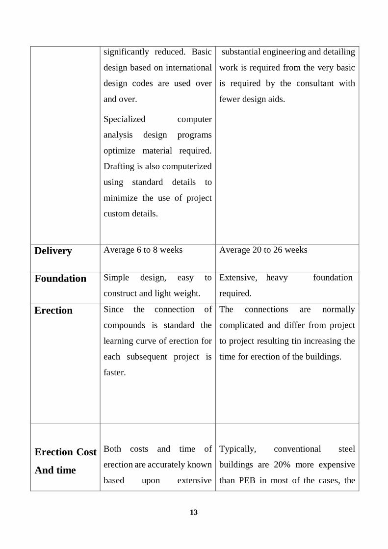
2.2.6 Pre-engineered Buildings vs. conventional buildings [16]
Property Pre-engineered Steel
buildings
Conventional Steel buildings
Structural
weight
Pre-engineered
buildings are on the
average 30% lighter
because of the efficient
use of steel. Primary
framing members are
tapered built up
section. With the large
depths in areas of
higher stress.
Secondary members
are light weight roll
formed z or c shaped
members
Primary steel members are
selected hot rolled t sections.
Which are, in many segments
of the members heavier than
what is actually required by
design? Members have
constant cross section
regardless of the varying
magnitude of the local stresses
along the member length.
Secondary members are
selected from standard hot
rolled sections which are much
heavier
Design Quick and efficient: since
PEB s are mainly formed by
standard sections and
connections design, time is
Each conventional steel structure is
designed from scratch with fewer
design aids available to the engineer.
13
significantly reduced. Basic
design based on international
design codes are used over
and over.
Specialized computer
analysis design programs
optimize material required.
Drafting is also computerized
using standard details to
minimize the use of project
custom details.
substantial engineering and detailing
work is required from the very basic
is required by the consultant with
fewer design aids.
Delivery Average 6 to 8 weeks Average 20 to 26 weeks
Foundation Simple design, easy to
construct and light weight.
Extensive, heavy foundation
required.
Erection
Since the connection of
compounds is standard the
learning curve of erection for
each subsequent project is
faster.
The connections are normally
complicated and differ from project
to project resulting tin increasing the
time for erection of the buildings.
Erection Cost
And time
Both costs and time of
erection are accurately known
based upon extensive
Typically, conventional steel
buildings are 20% more expensive
than PEB in most of the cases, the

14
experience with similar
buildings.
The erection process is faster
and much easier with very
less requirement for
equipment.
erection costs and time are not
estimated accurately.
Erection process is slow and
extensive field labour is required.
Heavy equipment is also needed.
Seismic
Resistance
The low weight flexible
frames offer higher resistance
to seismic forces.
Rigid heavy frames do not perform
well in seismic zones.
Over
All Price
Price per square meter may be
as
Low as by 30 % than the
conventional building.
Higher price per square meter.
Architecture Outstanding architectural
design can be achieved at low
cost using standard
architectural details and
interfaces.
Special architectural design and
features must be developed for each
project which often requires research
and thus resulting in higher cost.
Sourcing And
Coordination
Building is supplied complete
with all accessories including
erection for a single one stop
source.
Many sources of supply are there so
it becomes difficult to co-ordinate
and handle the things.

15
Cost of
Charge order
PEB manufactures usually
stock a large amount of that
can be flexibly used in many
types of PEB projects.
Substitution of hot rolled sections
infrequently rolled by mills is
expensive and time consuming.
Building
Accessories
Designed to fit the system
with standardized and inter
changeable parts. Including
pre designed flashing and
trims. Building accessories
are mass produced for
economy and are available
with the building.
Every project requires different and
special design accessories and special
sourcing for each item. Flashing and
trims must be uniquely designed and
fabricated.
Future
Expansion
Future expansion is very easy
and simple.
Future expansion is most tedious and
more costly.
Safety
Single source of
responsibility is there because
the entire job is being done by
one supplier.
Multiple responsibilities can result in
question of who is responsible when
the components do not fit in properly,
insufficient material is supplied or
parts fail to perform particularly at
the supplier/contractor interface.
All components have been
specified and designed
Components are custom designed for
a specific application on a specific

16
Performance
specially to act together as a
system for maximum
efficiency, precise fir and
peak performance in the field.
job. Design and detailing errors are
possible when assembling the diverse
components into unique buildings.
2.3 PRE-ENGINEERED BUILDINGS or (PEB)
2.3.1. General
India being a developed country massive house building construction is taking place in
various parts of the country.[10] Since 30% of Indian population lives in towns and
cities; hence construction is more in the urban places. The requirement of housing is
tremendous but there will always be a shortage of house availability as the present
masonry construction technology cannot meet the rising demand every year. Hence
one has to think for alternative construction system for steel or timber buildings, but
timber is anyway not suitable to tropical countries like India.
In structural engineering, a pre-engineered building (PEB ) is designed by a
manufacturer to be fabricated using a pre-determined inventory of raw materials and
manufacturing methods that can efficiently satisfy a wide range of structural and
aesthetic design requirements. Within some geographic industry sectors these
buildings are also called Pre-Engineered Metal Buildings. Historically, the primary
framing structure of a pre-engineered building is an assembly of I shaped members,
often referred as I beam. In PEB, I section beams used are usually formed by welding
together steel plates to form of I section. I section beams are then field-assembled (e.g.
bolted connections) to form the entire frame of the pre-engineered building. Cold

17
formed Z and C-shaped members may be used as secondary structural elements to
fasten and support the external cladding. Roll-formed profiled steel sheet, wood,
tensioned fabric, precast concrete, masonry block, glass curtain wall or other materials
may be used for the external cladding of the building.
In order to accurately design a pre-engineered building, engineers consider the clear
span between bearing points, bay spacing, roof slope, live loads, dead loads, collateral
loads, wind uplift, deflection criteria, internal crane system and maximum practical
size and weight of fabricated members. Historically, pre-engineered building
manufacturers have developed pre-calculated tables for different structural elements in
order to allow designers to select the most efficient I beams size for their projects.
In pre-engineered building concept the complete designing is done at the factory and
the building components are brought to the site in CKD (Completely knock down
condition). These components are then fixed / jointed at the site and raised with the
help of cranes. The pre-engineered building calls for very fast construction of buildings
and with good aesthetic looks and quality construction. Pre-engineered Buildings can
be used extensively for construction of industrial and residential buildings. The
buildings can be multi storied (4-6 floors). These buildings are suitable to various
environmental hazards. Pre-engineered buildings can be adapted to suit a wide variety
of structural applications; the greatest economy will be realized when utilizing standard
details. An efficiently designed pre-engineered building can be lighter than the
conventional steel buildings by up to 30%. Lighter weight equates to less steel and a
potential price savings in structural framework.
2.3.2 Features and Advantages
Features: Pre-engineered steel buildings use a combination of built-up sections, hot
rolled sections and cold formed elements which provide the basic steel frame work

18
with a choice of single skin sheeting with added insulation or insulated sandwich panels
for roofing and wall cladding. The concept is designed to provide a complete building
envelope system which is air tight, energy efficient, optimum in weight and cost and,
above all, designed to fit user requirement like a well fitted glove. [6]
Pre-engineered steel buildings can be fitted with different structural accessories
including mezzanine floors, canopies, fascias, interior partitions etc. and the building
is made water proof by use of special mastic beads, filler strips and trims. This is very
versatile buildings systems and can be finished internally to serve any functions and
accessorized externally to achieve attractive and unique designing styles. It is very
advantageous over the conventional buildings and is really helpful in the low rise
building design.
Pre-engineered buildings are generally low rise buildings however the maximum eave
height can go up to 25 to 30 metres. Low rise buildings are ideal for offices, houses,
showrooms, shop fronts etc. The application of pre-engineered buildings concept to
low raise buildings is very economical and speedy. Buildings can be constructed in less
than half the normal time especially when complemented with the other engineered
sub systems.
The most common and economical type of low rise buildings is a building with ground
floor and two intermediate floor plus roof. The roof of low rise buildings may be flat
or sloped. Intermediate floors of low rise buildings are made of mezzanine systems.
Single storied houses for living take minimum time for construction and can be built
in any type of geographical location like extreme cold hilly areas, high rain prone areas,
plain land obviously and extreme hot climatic zones as well.
Advantages:
Reduction in Construction Time: Buildings are typically delivered in just a few weeks
after approval of drawings. Foundation and anchor bolts are cast parallel with finished,
19
ready for the site bolting. In India the use of PEB will reduce total construction time of
the project by at least 50%. This also allows faster occupancy and earlier realization of
revenue.
Lower Cost: Due to the systems approach, there is a significant saving in design,
manufacturing and on site erection cost. The secondary members and cladding nest
together reducing transportation cost.
Flexibility of Expansion: Buildings can be easily expanded in length by adding
additional bays.
Also expansion in width and height is possible by pre designing for future expansion.
Larger Spans: Buildings can be supplied to around 80M clear spans.
Quality Control: As buildings are manufactured completely in the factory under
controlled conditions the quality is assured.
Low Maintenance: Buildings are supplied with high quality paint systems for
cladding and steel to suit ambient conditions at the site, which results in long durability
and low maintenance costs. Energy Efficient Roofing and Wall Systems: Buildings can
be supplied with polyurethane insulated panels or fiberglass blankets insulation to
achieve required U values [16]].
Architectural Versatility: Building can be supplied with various types of fascias,
canopies, and curved eaves and are designed to receive pre-cast concrete wall panels,
curtain walls, block walls and other wall systems.
Single Source Availability: As the complete building package is supplied by a single
vendor, compatibility of all the building components and accessories is assured. This
is one of the major benefits of the pre-engineered building systems.
2.3.3 Benefits of PEB:
Pre-engineered building systems provide real value to clients without sacrificing
durability, seismic and wind resistance, or aesthetic appearance. Cost savings begin

20
right at the drawing preparation stage. Systems engineering and fabrication methods
help reduce interim financing costs through faster construction and minimized field
erection expense. An added benefit is earlier occupancy of the facility and a head start
on day-to-day operations by the client.
Apart from costs, there is an assurance of factory-built quality and uniformity in design
and fabrication. These systems are also energy efficient; incorporate watertight roofing
systems; enable easy disassembly or future expansion and have the lowest life cycle
maintenance costs.
Adding to these; there is no mess of sand and cement; power savings; walkable
ceilings; progressive and non-progressive panel systems for walls. A poor man can be
provided with a home created under strict quality control and having a longer life span,
with greater safety against natural disasters like earthquakes and cyclones.
Moreover, it is possible to create the building in required form and shape. And the
'system approach' renders a holistic way of thinking at one platform for consultants,
designers, architects, and builders. Thus it tends to achieve a perfect harmony among
various stringent specifications and aesthetic requirements in a most economical way.
In nutshell, the benefits may be summarized as under
• Easy future expansion/modification.
• Weather proof and fire hazards.
• Optimized design of steel reducing weight.
• International Quality Standards
• Seismic & Wind pressure resistant.
• Quality design, manufacturing and erection, saving around 30-40% of project
time
• Quick delivery and Quick turn-key construction.
• Pre-painted and has low maintenance requirement.

21
• Erection of the building is fast.
• The building can be dismantled and relocated easily.
• Future extensions can be easily accommodated without much hassle.
• Increased Life cycle performance and cost competitiveness
• Environment friendly structures
• Better rainwater harvesting through gutters and down-take arrangements
• Lighter weight; savings in foundation cost of 10-20 percent
• The building can be dismantled and relocated easily
• Easy integration of all construction materials
• Energy efficient roof and wall system using insulations.
• Suitability for Hilly regions and other geographically difficult areas
• Unlimited architectural possibilities
2.3.4 Applications of PEB
Almost every conceivable building use has been achieved with PEB the most common
applications are industrial, institutional and commercial.
In India, Pre-engineered building systems find application primarily in the construction
of Warehouses, & Industrial sheds & Buildings. The recent focus has also shifted to
cover rural as well as urban, individual and mass housing projects, farmhouses, slum
re-organization projects and rehabilitation projects, amenity structures like health
centre, kiosks, primary schools, panchayats etc. The pharmaceutical industries and
exhibition centre, and functional requirements like offices, seminar halls, call centre,
supermarkets, showrooms etc. [6] have also attracted PEB. Earthquake-resistant
buildings are the recent applications of PEB with wide and immediate acceptance.
PEB concept has acted as a catalyst in the infrastructure development of the country.
Single storied houses for living take minimum time for construction and can be built

22
in any type of geographic location like extreme cold hilly areas, high rain prone areas,
plain land, extreme hot climatic zones etc.
Applications of Pre-engineered steel buildings include
• Houses & Living Shelters
• Factories
• Warehouses
• Sport Halls ( Indoor and Outdoor)
• Aircraft Hangers
• Supermarkets
• Workshops
• Office Buildings
• Labour Camps
• Petrol Pumps/Service Buildings
• Schools
• Community centres
• Railway Stations
• Equipment housing/shelters.
There is a great possibility of improving the aesthetic quality with a choice of roofing
elements, exterior finishes, weather-sheds, colour system and variations in planning as
well as massing.
2.4 PROFILE OF PEB
All over the world, pre-engineered building system or PEB system is becoming an
eminent segment in pre-engineered construction industry. It has become possible
because pre-engineered building system encompasses all the characteristics that are

23
compatible to modern demands viz. speed, quality and value for money. Pre-
engineered buildings find many pre-engineered construction applications, which could
be intrinsic and high-end.
PEB prospect in the world:
Technological improvement over the year has contributed immensely to the
enhancement of quality of life through various new products and services. One such
revolution was the pre-engineered buildings. Through its origin can be traced back to
1960 s its potential has been felt only during the recent years. This was mainly due to
the development in technology, which helped in computerizing the design.
PEB concept has been very successful and well established in North America, Australia
and is presently expanding in U.K and European countries. PEB construction is 30 to
40% faster than masonry construction. PEB buildings provide good insulation effect
and would be highly suitable for a tropical country like India. PEB is ideal for
construction in remote & hilly areas. [16]. A recent survey by the Metal Building
Associations (MBMA) shows that about 60% of the non- residential low rises building
in USA are pre-engineered buildings.
MARKET POTENTIAL
PEB systems are extensively used in industrial and many other non- residential
constructions worldwide, it is relatively a new concept in India. These concepts were
introduced to the Indian markets lately in the late 1990 s with the opening up of the
economy and a number of multi nationals setting up their projects. The market potential
of PEB is 12 lakh Metric tonnes per annum. The current pre-engineered steel building
manufacturing capacity is 0.35 million tonnes per annum. The industry is growing at
the compound rate of 25 to 30 %. [16]
24
FUTURE OF PEB
The steel structures (SS) market in India is in excess of 4.5 Mn.MT, growing at a rapid
pace of more than 10% p.a. over the past few years. This market has experienced a
higher growth compared to both Indian steel industry as well as Indian construction
GDP. Overall construction sector accounts for majority (greater than 80%) of the steel
structures market (volume terms) in India.
The current pre-engineered steel building manufacturing capacity is 0.35
million tonnes per annum. The industry is growing at the compound rate of 25 to 30%.
2.4.1 PRODUCTION
Pre-engineered Steel Buildings are tailor made buildings which are those fully
manufactured in the factory after designing. This fabrication is done in a controlled
environment with latest technology. The production is done under standard conditions.
The Raw material required is imported from major companies like Tata BlueScope to
all the companies in India.
Historically, the primary framing structure of a pre-engineered building is an
assembly of I shaped members, often referred as I beam. In pre-engineered buildings,
I beams used are usually formed by welding web and flange plates together to form I
section. I beams are then field assembled (e.g. bolted connections) to form the entire
frame of the pre-engineered building. Some manufacturers taper the framing members
(varying in web depth) according to the local loading effects. Larger plate dimensions
are used in areas of higher load effects.
Cold formed Z and C-shaped members may be used as secondary structural
elements to fasten and support the external cladding. Roll-formed profiled steel sheet,
wood, tensioned fabric, precast concrete, masonry block, glass curtain wall or other
materials may be used for the external cladding of the building.

25
2.4.2 MANUFACTURING OR PROCESSING
Manufacturing is done through the raw material which is imported from steel
production companies. The imported steel is in the form of rolled sheets. For the hot
rolled and cold formed sheets cutting is done to desired dimensions and welded with
submerged arc welding.
The PEB production process primarily consists of FOUR major parallel processing
lines, as under:
1. Built-up members for Primary frame
2. Cold forming for Secondary framing
3. Profiling for Roof and Wall
sheeting
4. Accessories & Bracings like
Gutters, down take pipes, ridge
Vents, Skylights, clips etc.
The design and final processing inspection is done for production, ready for shipment
in completely knocked Down Condition (CKD) conditions.
1. Plate cutting using Shear/Plasma/Multi-torch through nesting software for
optimized use of plate area.
2. H-beam welding on automatic welding machines using SAW or MIG welding
process
3. Fabrication for fitments like end plates, stiffeners and connections cleats.
4. Cleaning the surface for painting
5. Slitting HR coils for cold forming operations to make Z and C sections with
punching

26
6. Cutting and threading sag rods and bracing rods
7. Fabrication of Diagonal bracing angles or pipes
8. Profiling the Galvalume / Zincvalume sheets for roofing and wall cladding
9. Manufacturing Gutters, down take pipes in press bend
10. Procuring and assigning required matching fasteners for connections
11. Organizing some bought out accessories
12. Quality control tests & inspection; and matching with project wise Bill of
Quantities as given by the engineering department.
13. Dispatching to project sites as per sequence of erection
2.4.3 STRUCTURAL FRAMING
All framing members shall be shop fabricated for field bolted assembly. The surfaces
of the Bolted connections shall be smooth and free from burrs or distortions. All shop
connections shall be in accordance with the manufacturer's standard design practices.
Primary framing
All rigid frames shall be welded built-up "I" sections or hot-rolled sections. The
columns and the rafters may be either uniform depth or tapered. Flanges shall be
connected to webs by means of a continuous fillet weld on one side. All end wall roof
beams and end wall columns are in cold formed "C" sections, mill-rolled sections, or
built-up "I" sections depending on design requirements. All base plates, splice and
flanges shall be shop fabricated to include bolt connection holes. Webs are shop
fabricated to include bracing holes. [16]
Secondary Framing
Purlins and girts shall be cold-formed "Z" sections with stiffened flanges. Flange
stiffeners shall be sized to comply with the requirements of the latest edition of AISI.
Purlin and girt flanges shall be unequal in width to allow for easier nesting during

27
erection. They shall be pre punched at the factory to provide for field bolting to the
rigid frames. They shall be simple or continuous span as required by design.
Connection bolts will install through the webs, not flanges. [16]
Bracing
Diagonal bracing in the roof and sidewalls shall be used to remove longitudinal loads
(wind, crane, etc.) from the structure. This bracing will be furnished to length and
equipped with bevel washers and nuts at each end. It may consist of rods threaded each
end or galvanized cable with suitable threaded end anchors. If load requirements so
dictate, bracing may be of structural angle and/or pipe, bolted in place. [16]
Welding
Welding is a fabrication or sculptural process that joins materials, usually metals. In
Pre-engineered Steel Buildings the hot rolled steel sections are subjected to submerged
arc welding. Shielding gas is used in order to protect the welding region. Welding is
Done by passing the Steel plates into the welding machine, which welds along the
joints. In PEB the Tapered sections are welded, but at some locations manual welding
is done. Double side welding is preferred according to Indian Code but Single side
Welding is much beneficent because it increases the Quality of steel sections. Single
side welding is more economical, all manufactures follow the American code which
states Single side welding.
Base plates are welded to base of columns for the structural strength. These base plates
are provided with bolt holes. Anchor bolt dimensions are taken into account for Base
plate preparation. [16]
Anchor Bolts:
Anchor bolts are manufactured with circular steel rods having threading portion at the
top for bolting and bent up at the bottom for Foundation. These are bent at 90 degrees

28
for embedding into the soil. The dimensions for Anchor bolts are taken from support
reactions of the columns.
Surface Preparation:
The surface of columns and rafters are prepared in order to protect it from rusting.
Abrasive paper is used to scrub the top layers of columns and rafters in order to remove
accumulated rust on the top of the sections. This is old method, it is done manually.
Advancement technologies avoided manual procedure and brought Sand blasting and
short blasting into existence.
Sand blasting: Sand Blasting is a method in which sand is blown with high velocities
to the members. This is blown with sand particularly with 2 to 4 mm thick sand and
surface is cleared.
Short Blasting: Short blasting is a latest process in which members are sent into the
machine and hit with iron balls of 3mm thick under a huge velocity. Periodical removal
of rust is done in case of short blasting. Short blasting is observed as more efficient
surface cleaning process
Varnishing or Painting: Normally the primary and secondary steel are coated with
one coat (35 microns) of red oxide paint without any special treatment to steel.
However, if some special paint has to be applied to steel in order to give better anti-
corrosion properties etc. then the steel members have to be shot-blasted and then coated
with the special paints.
2.4.5 ERECTION
Steel construction is considered as a process that involves many related activities. Pre-
engineered buildings (PEB) steel parts are required to be installed in a specific order
due to structural safety requirements and to the logical sequence of erection. However,
29
shipping, transportation, unloading and on-site storage does not take into account the
erection order of the assembly. As a result, considerable time is consumed locating,
sorting, and identifying steel Components.
Integrating promising information technologies such as radio frequency identification
(RFID), mobile computing devices and wireless technology can be useful in improving
the effectiveness and convenience of information flow in construction projects. Pre-
engineered buildings require repetitive operations and assembly of many structural
elements.
Pre-engineered buildings (PEB) steel parts are required to be installed in a specific order
due to structural safety requirements and to the logical sequence of erection.
Erection Drawings:
Erection drawings provide the field erection crew (raising gang) with the roadmap of
how to erect (put together) the steel assemblies after they are delivered to the field.
Essentially, they are a set of instructions on how to put the puzzle pieces together.
Every assembly shipped to the field is given a shipping piece number to identify it.
This number is noted on the drawing and is also stenciled onto the actual assembly of
steel. Erection drawings illustrate how the connections will be fabricated in the field.
2.4.6 CONSTRUCTION OVERVIEW:
Before the PEB Components arrives, the site and foundation should be prepared. This
includes levelling the terrain and constructing the foundation.
A. Remove trees, debris, and other items from the building
location.
B. Smooth and level the ground where the foundation is to be
made.

30
C. Construct the foundation using the materials recommended as per design parameters.
Transiting on all corners the foundation locations are determined and trenches are made
for foundation. In foundation trenches the Anchor bolts are set along with the concrete.
Anchor Bolt Setting:
It is extremely important that anchor bolts be placed accurately in accordance with the
anchor bolt setting plan. All anchor bolts should be held in place with a template or
similar means, so that they will remain plumb and in the correct location during placing
of the concrete. Check the concrete forms and anchor bolt locations prior to the pouring
of the concrete. A final check should be made after the completion of the concrete work
and prior to the steel erection. This will allow any necessary corrections to be made
before the costly erection labor and equipment arrives.
Unloading and Preparing Parts assembly:
The vehicle transporting your building parts must gain access to the building site from
the adjacent highway or road. Such access should be studied and prepared in advance
of arrival. When the truck arrives with the building, unload the truck promptly, stack
the steel parts evenly on blocks and protect them from the weather. Unloading and
placing the steel parts of the building in the most convenient places for assembly will
make the process easier and faster.
Blocking under the columns and rafters protects the splice plates and the slab from
damage during the unloading process. Extra care should always be exercised in the
unloading operation to prevent injuries from handling the steel and to prevent damage
to materials.
If water is allowed to remain for extended periods in bundles of primed parts such as
girts, purlins, etc., the pigment will fade and the paint will gradually soften reducing
its bond to the steel. Therefore, upon receipt of a job, all bundles of primed parts should
be stored at an angle to allow any trapped water to drain away and permit air circulation

31
for drying. Puddles of water should not be allowed to collect and remain on columns
or rafters for the same reason.
Location of Building Parts:
All the parts are placed around the foundation so that they will be in the most
convenient locations for installation. Bolts and nuts are placed where they will be
accessible to the parts. Purlins and girts, depending on the number of bundles, are
usually stored near the sidewalls clear of other packages or parts. Sheet packages are
usually located along one or both sidewalls off the ground and sloping to one end to
encourage drainage in case of rain. Accessories are usually unloaded on a corner of the
slab or off the slab near one end of the building to keep them as much out of the way
as possible from the active area during steel erection.
2.4.7 COMPONENTS ERECTION
The major components comprise of rigid frame, columns and rafter, eave struts, purlins,
girts, flange braces, end-wall columns and bracing systems which may be cables, rods
angles or portals. All materials for the first bay erection are prepared. The rafter sections
required are identified by part number, and then assembled as near as possible to their
lifting positions. Then the first four columns are erected at the braced bay, meanwhile
the part number, Orientation and position over anchor bolts were verified. Next step is
to position the crane for lifting the assembled rafter sections.
Raising Rigid Frames:
The intermediate or interior frames nearest the bearing end wall are usually erected
first. This bay usually contains the diagonal bracing. The proper completion and
plumbing of this first bay is extremely important to the successful completion of the
building. Although several methods are used to erect rigid frames, it has been found

32
most satisfactory to erect the columns first, tie them together with the girt and tighten
the anchor bolts. On small spans and short eave heights, columns can often be set in
place by hand without the use of hoisting equipment. Temporary bracing should always
be installed as soon as sections are lifted in place.
Completing and Plumbing the First Bay:
After the first intermediate or interior frames have been set, all purlins, girts, and eave
struts be installed in the braced bay and the entire bay plumbed, aligned and braced
before proceeding further. If the building is designed without cable bracing, the erector
is responsible for providing temporary erection bracing. When this bay is properly and
accurately plumbed and braced, the remaining members, to a large degree, will
automatically plumb and align when installed.
After the columns have been erected, the ground-assembled rafter is hoisted into place
and connected to the columns. The size of the rafter that can be safely handled depends
on the equipment available and the experience of the erection foreman. Generally as
many connections as possible are made on the ground.
The flange brace should be bolted to the rafter prior to raising in order to save time. The
hoisting equipment should never be released from the rafter until the frame is adequately
braced, so it cannot buckle or tip in the longitudinal direction of the building. The same
general procedures of erection apply to either clear span or multiple span frames.
Two words of caution concerning the erection of rigid frames are in order. The first is
that rigid frames, especially free ends or cantilevered sections should never be left for
the day in an unsupported, unbraced condition. Such practice has resulted in the total
loss of considerable amounts of erected steel because of wind. The second word of
caution pertains to the additional care required in the erection of multiple span frames
compared to clear span frames. Frames with interior columns, because of closer
supports, have much lighter sections. They are much more apt to buckle during erection
than clear span frames, and consequently require greater care in rigging and handling.

33
Erecting column Beam end walls:
Column and beam end walls of 50 feet or less in span may be raised into position and
set on the anchor bolts as a unit. All rafters, column, girts (except outside end wall girts
which connect to the sidewall girts), door headers, door jambs, clips, diagonal brace
rods, etc. should be assembled on the ground with the bolts left finger tight. A spreader
bar should be used to raise the end wall frame. Because of the flexibility of the column
and beam frames, care must be taken in locating the points of attachment of the cables,
and in raising the frame, to avoid bending about the minor axis.
For spans of 60 feet and greater, the columns are usually erected first and then capped
with the end wall rafter. Girts, headers, jambs and diagonal brace rods are then added
between the end columns. During this erection process, the frame must be properly
braced or guyed before the lifting lines are disengaged. Final bolt tightening should be
done once the frame is plumb and square.
Erecting the remaining frames:
The remaining frames are erected in like manner, initially with only a few purlins being
installed in each bay, as shown below, working from one end of the building to the
other. To lend overall rigidity to the structure, install flange braces to the purlins at
specified locations. All purlin, girt and eave strut connection bolts are left loose so that
the entire skeleton framework can be plumbed without undue difficulty. The remaining
purlins can be positioned on the rafter in each bay to facilitate the completion of the
roof framing.
Installation of Bracing:
Diagonal bracing in metal buildings is critical. They provide support for wind loads or
other longitudinal loads, such as those created by an overhead crane in the completed
structure. Many times additional temporary bracing is needed to stabilize the structure
during erection. On some smaller buildings, diagonal bracing is not needed for the
building design, so the erector must furnish any erection bracing needed.

34
Assemble the next brace cable the same way and connect to the next column to form
an X with the other cable. To square the building, measure the length of the diagonal
cables and tighten or loosen the turnbuckle/eye-bolt until the cable lengths are the
same. Brace each sidewall frame the same way so that you have an x-brace on each
side. Tighten the column anchor nuts after insuring that the building is square.
The diagonal bracing is cable. It should always be installed as shown on the erection
drawing and should be tensioned so that the building will not sway or rock when the
wind blows. Care should be taken, however, not to over tighten and bend the structural
members. The workman should watch the structural members carefully as he tightens
the bracing. Occasionally the bracing in the wall of a building cannot be installed in
the specified bay because of doors or other complications. Usually these can be moved
to other bays without affecting the structural integrity of the building.
Bolting Procedure in steel structures:
This procedure applies to the permanent fixing of steel structures including the erection
of steel. Construction drawings shall indicate the grade and diameter of all bolts, nuts
and washers required for the construction. Drawings shall indicate whether a Friction-
Type or Bearing Type connection is required. The nominal size of the bolt holes (other
than holes in a base plate) shall be 2mm larger than the nominal bolt diameter for a bolt
not greater than 24mm in diameter and not more than 3mm larger for bolts of diameter
more than 24 mm.
Alignment and assembly
The parts to be joined shall line up in such a way that a drift of equal diameter to the
bolt can pass through the bolt holes. Drifting to align the bolt holes shall be done is
such a 3 way as not to bend or damage the parts nor enlarge the holes. Packing shall be
provided as required to ensure parts have full contact over the mating surfaces. Prior
to inserting the bolts the nut should be run up the threads to ensure there are no thread
defects that would impede the tightening process.

35
Bolts shall be inserted through the holes after alignment from such a direction that the
nut has easiest access for tightening.
Bolt Tightening (Snug Tightening)
Bolt Tightening is required for all Bearing-Type Connections and as a pre-requisite to
Friction Type connections. The sequence of tightening the bolts shall proceed from the
stiffest part of the connection towards the free edges. High strength bolts that are to be
tensioned may be tightened during erection to facilitate assembly but they shall not be
finally tensioned until all bolts have been snug tightened in the correct sequence. Bolt
tightening is also known as snug-tightening. Bolt or snug tightening is achieved either
by subjecting the nut to a few impacts of an impact wrench after standard effort
tightening with a spanner or by the full effort of a person using a standard spanner. The
sequence of tightening is to firstly tighten all nuts with a standard effort and then to
snug tighten using a full effort or an impact wrench.
Wall Insulation
Fiberglass blanket insulation is the most common type used, and these instructions
pertain to this type only. One side of the blanket insulation should have a vapour barrier
that must face the inside of the building regardless of whether the insulation is for
heating or cooling.
Cut the insulation to length allowing an additional 6 or more to facilitate handling. The
wall panel can be used as a guide. The first run of wall insulation should be installed
so that its forward edge is just ahead of the leading edge of the wall panel. This keeps
the forward edge of the insulation ahead of the wall panel for joining the next blanket.
Roof Insulation:
Pre-cut roof insulation to reach from eave to eave allowing approximately 2 feet of
additional length to facilitate handling. Hold insulation at one sidewall and roll out
insulation across the purlins, vapour barrier to the inside of the building. Stretch the

36
insulation to provide a tight and smooth inside surface. Double sided tape or contact
adhesives can be used to hold insulation in place while the roof sheets are being
installed. Trim excess insulation to the edge of the eave trim and cut fiberglass
approximately 4 inches from end leaving only facing. Fold facing over end of blanket
insulation to seal the end.
Aligning the Girts:
Installation of the building walls is generally done before the roof. Before starting the
wall installation, check to be sure that the eave strut and girts are straight and plumb.
One method of aligning the Girts is to cut temporary wood blocking to the proper length
and install between the lines of girts. This blocking can be moved from bay to bay,
which will reduce the number of pieces required. Normally, one line of blocking per
bay will be sufficient. Banding can also be used to hold the girt straight and plumb.
Screw alignment:
Good alignment of the screws, especially on the wall panels, will give a professional
appearance to the wall panel installation. One way this can be accomplished is by pre-
drilling holes in the panels at identical locations. Up to 15 panels can be stacked
together and drilled using a template panel. 1/8 or 5/32 diameter drill bit is used for
panel to structural fasteners and a 1/4 diameter bit for the side lap clearance holes.
Installation of wall Panels:
Adjoining panels are installed with the overlapping rib toward the last erected panel.
Position panel to structural making sure that it is kept plumb and install fasteners at
lapped rib. Check for proper coverage and correct as necessary. Install remaining
fasteners.

37
Fastener Installation:
Correct fastener installation is one of the most critical steps when installing roof panels.
Drive the fastener in until it is tight and the washer is firmly seated. Do not overdrive
fasteners: A slight extrusion of neoprene around the washer is a good visual tightness
check.
Always use the proper tool to install fasteners. A fastener driver (screw gun) with and
rpm of 1700-2500 is used for self-drilling screws.
Preparing the Eave:
After installing the first run of insulation, prepare the eave for the first roof panel by
applying tape sealant along the eave outside of the insulation and leaving release paper
in place. Sealant must be applied in a straight line and without voids. Splice a full
closure to the starting closure and apply along the top of the eave sealant. If roof is
subject to ice and snow build-up, the splice in the closure strip must be caulked to
insure weather tightness.
Installation of the first roof panel:
Once the eave is prepared, the first roof panel may be installed. The roof panel is set in
place over the inside closure (after removing the paper from the mastic) ensuring the
major ribs of the panel nest properly with the inside closure.
Align the centre of the major rib of the panel edge with the edge of the end wall
roofline. With the panel properly placed, secure the panel to the structure with
appropriate fasteners.
38
Roof Sheeting Sequence:
It is recommended that both sides of the ridge of a building be sheeted simultaneously.
This will keep the insulation covered for the maximum amount of time and the panel
ribs can be kept in proper alignment for the ridge panel.
Final Installation:
While back lapping the last roof panel (to match panel coverage with the building
length) is routinely done, this installation method can compromise the integrity of the
roof by trapping moisture between the panels. This moisture could, in time, create an
environment conducive to rust and metal failure. Manufacturer recommends field
cutting the final panel lengthwise to create the desired panel width necessary to finish
off the building. The cut edge of the panel should always be installed on the outside
edge, not the lap edge. The narrow panel should be handled with care, and foot traffic
avoided until the final panel is completely installed.
Skylight Installation:
Skylight panels are installed using the same procedures as a steel panel. Care should
be taken when installing fasteners in the skylights to avoid cracking the material. Install
roof panels, leaving the light-transmitting panel run open, except for lower light
transmitting panel run panel. Install tape sealer to panel side laps and across panel
width as normal. Lay light transmitting panel in place overlapping lower metal panel
[6]. Apply double run of tape sealer across light transmitting panel width at lower and
middle purlins.

39
2.5 SCOPE FOR FUTURE STUDY
2.5.1. TRACKING GROWTH OF PEB
Emerging from their hiding places in concrete columns pre-engineered steel structures
(PEB s) are innovative solutions for construction projects across several sectors now
as discovers.
As Infrastructure construction across the country is combining speed, economy,
safety, strength and aesthetics at awe inspiring levels, steel structures, until now a
primary foundation element, have risen as complete solutions in construction projects
for various structural requirements. India is growing fast as an economy for pre-
engineered buildings (PEB s) as it is witnessing a boom in the infrastructure sector.
Structural steel buildings or PEB s are addressing parameters including finishes,
environment control and life cycle with a panache derived from product innovation
and technology advancement.
Emerging as a strong alternative to conventional concrete construction methods, PEB
in India is validated by the 33% market share of PEB s in the construction industry.
While this figure is lower than some European countries, it marks India's growing
global market share at 9.5 percent -- a step ahead of China's 8.5 percent. "The market
demand is pegged at 425,000 TPA with a 15% growth per annum,"(Kirby). "Current
market size is around Rs.3.500 Crores and it is expected to grow at 10% to 15% per
year,"
Strength Building:
With the country's five year plan catering for infrastructure addition in the form of
airports, metros and bridges sector differentiation is expected to separate industrial
buildings and building systems. These include Design & Engineering, Manufacture
and Construction & Erection. This pattern of restructuring indicates an industry that

40
sees PEB s coming into its own with experiencing exponential growth with
diversification into various sectors and segments.
Add to that the reduced time to completion with the benefit of quality, and there is recipe
for success.
"PEB is getting its due credit as a favourable alternative construction methodology in
India today. More sectors are realizing the benefits of metal over brick and mortar.
The scope of metal/steel buildings is very vast for the Indian market. PEB proves to
be relevant and beneficial to several construction verticals including warehousing,
infrastructure, oil & gas refineries as well as group housing,"(Kirby). "The advantages
of having a steel structure or building over traditional concrete are far too many.
Primarily, speed and quality of construction are the top two benefits. Steel buildings
are fire, quake and cyclone resistant hence from a safety and longevity perspective,
these buildings are timeless".
2.5.2 SCOPE FOR FUTURE STUDY
Multi Storey Buildings:
PEB has boon to Multi storey Buildings in India. Decking sheets with concrete over
can be used as roofing and raised to any extent above 40 meters. These have a tracking
rate of 80% in western countries.
Fibre Glass Wool Insulation for PEB:
A critical and necessary ingredient in the PEB System is thermal and acoustic
insulation. This is necessary to minimize heat gain (or energy loss, for an air
conditioned building) as well as to provide acoustic insulation from heavy rain and
other outside noises. In a typical PEB structure, the roof accounts for approx. 40 to
50% of total heat gain, while walls account for approx. 15 to 20% of heat gain. [6]

41
Almost 100% of PEB s world-wide are insulated for the following reasons.
• Minimize heat gain
• Maximize thermal comfort
• Minimize energy loss, cooling load and operating cost for air conditioned
buildings
• Provide acoustic insulation
• Prevent unwanted moisture condensation
Cellular Columns or Rafters:
Cellular beams can achieve the same strength as solid I beams of the same depth with
significantly less steel use resulting in Lighter weight. These beams offer designers a
number of opportunities for sizes and sections including varying the depth of the beam
and creating tapered sections.
Standard Seam Roofina:
Standard Seam roofina which is particularly used for sheeting. Sheets are not punched
and rolled to one above the other in order to protect leakage of water during rains.

42
CHAPTER 3
METHODOLOGY
3.1 GENERAL:
Pre-engineered Buildings are custom designed to meet client s requirements. PEB are
defined for definite measurements. The produced members fit to the designed
dimensions. Measurements are taken accurately for the requirements. The basic
parameters that can define a PEB are as follows.
3.1.2 WIDTH OR SPAN OF BUILDING:
The centre to centre length from one end wall column to the other end wall column of
a frame is considered breadth or span of the building. The width between two columns
can be measured as span. The span length for different buildings varies. The design is
done on span length given by customer. [16] The basic span length starts from 10 to
150 meters or above with intermediate columns. Aircraft hangars, manufacturing
industries, Stadiums possess major span width. No modifications or extending span be
done.
3.1.3 LENGTH OF BUILDING:
The length of PEB is the total length extending from one front end to the rear end of the
building. The length of PEB can be extendable in future.
3.1.4 BUILDING HEIGHT:
Building height is the eave height which usually is the distance from the bottom of the
main frame column base plate to the top outer point of the eave strut. When columns
are recessed or elevated from finished floor, eave height is the distance from finished
floor level to top of eave strut.

43
3.1.5 ROOF SLOPE:
This is the angle of the roof with respect to the horizontal. The most common roof
slopes are 1/10 and 1/20 for tropical countries like India. The roof slope in snow fall
locations can go up to 1/30 to 1/60. Any practical roof slope is possible as per customer
s requirement.
3.1.6 DESIGN LOADS:
Unless otherwise specified per-engineered buildings are designed for the following
minimum loads. The designed loads play a crucial role in case of PEB. The failure of
the structures occurs if not properly designed for loads.
The determination of the loads acting on a structure is a complex problem. The nature
of the loads varies essentially with the architectural design, the materials, and the
location of the structure. Loading conditions on the same structure may change from
time to time, or may change rapidly with time.
Loads are usually classified into two broad groups as dead loads and live loads. Dead
loads (DL) are essentially constant during the life of the structure and normally consist
of the weight of the structural elements. On the other hand, live loads (LL) usually vary
greatly. The weight of occupants, snow and vehicles, and the forces induced by wind
or earthquakes are examples of live loads. The magnitudes of these loads are not known
with great accuracy and the design values must depend on the intended use of the
structure. [6]
Dead Load:
The structure first of all carries the dead load, which includes its own weight, the weight
of any permanent non-structural partitions, built-in cupboards, floor surfacing
materials and other finishes. It can be worked out precisely from the known weights of
the materials and the dimensions on the working drawings.

44
Live Load:
All the movable objects in a building such as people, desks, cupboards and filing
cabinets produce an imposed load on the structure. This loading may come and go with
the result that its intensity will vary considerably. At one moment a room may be
empty, yet at another packed with people. Imagine the `extra' live load at a lively party.
Wind loads:
Wind has become a very important load in recent years due to the extensive use of
lighter materials and more efficient building techniques. A building built with heavy
masonry, timber tiled roof may not be affected by the wind load, but on the other hand
the structural design of a modern light gauge steel framed building is dominated by the
wind load, which will affect its strength, stability and serviceability. The wind acts both
on the main structure and on the individual cladding units. The structure has to be
braced to resist the horizontal load and anchored to the ground to prevent the whole
building from being blown away, if the dead weight of the building is not sufficient to
hold it down. The cladding has to be securely fixed to prevent the wind from ripping it
away from the structure.
Roof load:
Live loads produced by maintenance activities, rain, erection activities, and other
movable or moving loads by not including wind, snow, seismic, crane, or dead loads.
Roof snow load:
Gravity load induced by the forces of wind blowing from any horizontal direction.
Collateral loads:
The weight of any non-moving equipment or material such ceilings, electrical or
mechanical equipment, sprinkler system, or plumbing.
Auxiliary loads:
45
Dynamic loads induced by cranes, conveyers, or other material handling systems.
Seismic loads:
Horizontal loads acting in any direction structural systems due to action of an
earthquake.
Floor Live loads:
Loads induced on a floor system by occupants of a building and their furniture,
equipment, etc.
3.1.7 BAY SPACING:
The distance between the two adjacent frames of a building is called as a Bay spacing.
The spacing between two frames is a bay. End Bay length is the distance from outside
of the outer flange of end wall columns of centre line of the first interior frame columns.
Interior bay length is the distance between the centre lines of two adjacent interior main
frames Columns. The most economical bay spacing is 7.5m to 8.0m. However bay
length up to 10m is possible.
3.1.8 TYPES OF FRAME:
A frame is a combination of Columns and inclined beams (rafters). There are
various type of frames. [6]
Clear Span (CS):
The span length between two columns without any obstruction. It has split Beams with
ridge line at the peak or centre of the building. The maximum practical width or span
is up to 90 meters, but it can also be extended up to 150 meters in case of Aircraft
Hangars. Arched Clear Span: The column is an RF column while the Rafter is curved.
It has no ridge line and peak. The curved roof rafter is used in for aesthetic look. The
maximum practical is up to 90 meters, but can be extended to 120 meters.
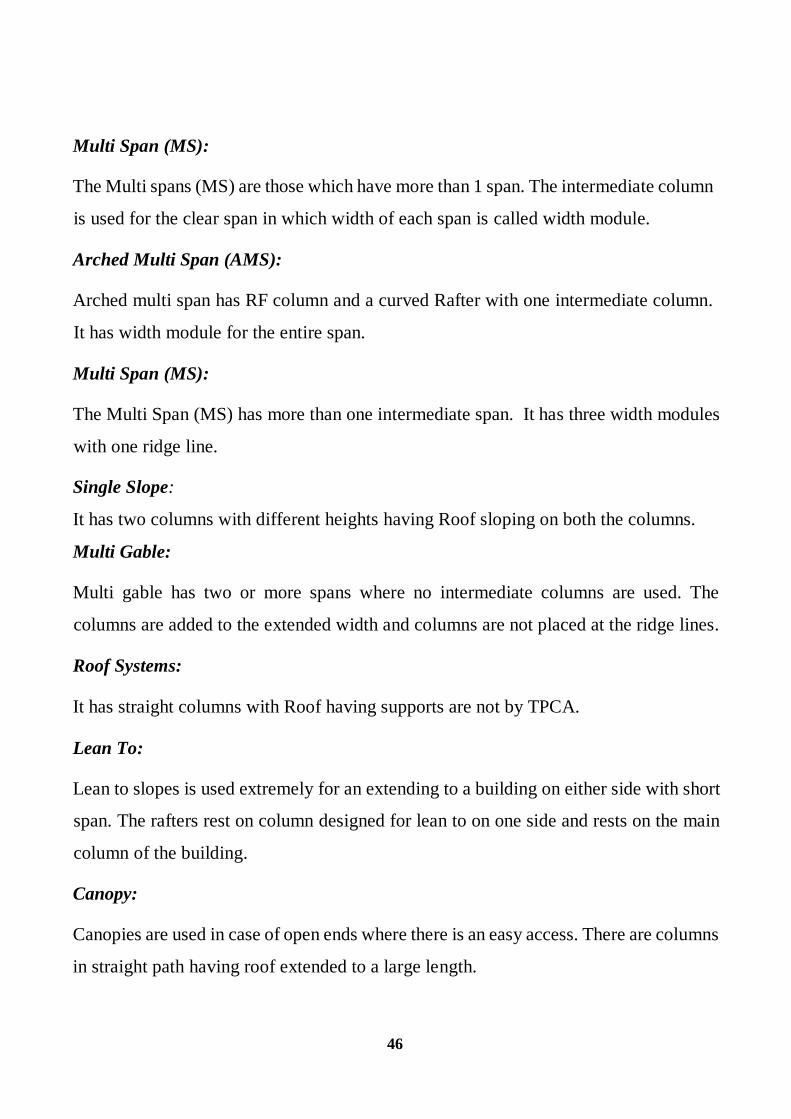
46
Multi Span (MS):
The Multi spans (MS) are those which have more than 1 span. The intermediate column
is used for the clear span in which width of each span is called width module.
Arched Multi Span (AMS):
Arched multi span has RF column and a curved Rafter with one intermediate column.
It has width module for the entire span.
Multi Span (MS):
The Multi Span (MS) has more than one intermediate span. It has three width modules
with one ridge line.
Single Slope:
It has two columns with different heights having Roof sloping on both the columns.
Multi Gable:
Multi gable has two or more spans where no intermediate columns are used. The
columns are added to the extended width and columns are not placed at the ridge lines.
Roof Systems:
It has straight columns with Roof having supports are not by TPCA.
Lean To:
Lean to slopes is used extremely for an extending to a building on either side with short
span. The rafters rest on column designed for lean to on one side and rests on the main
column of the building.
Canopy:
Canopies are used in case of open ends where there is an easy access. There are columns
in straight path having roof extended to a large length.

47
3.1.9 SUBSYSTEMS
Major companies use standard components and designs to manufacture a wide range
of structural subsystems according to customers' requirements. These structural
subsystems fulfil the requirements of two type’s viz. Aesthetic and Functional. They
produce a large number of structural subsystems according to exact specifications as
the strength of the pre-engineered building system depends largely on various
incorporated structural subsystems. Subsystems are available for following structures
End wall Roof Extension: End wall roof extensions consist of end wall panel, Roof
panel, Gable trim, soffit panel, and end wall rafter. The end wall is extended to an
extent under end wall panel support.
Sidewall Roof Extension: The sidewall roof extension has the same assembly but the
soffit panels are above the Roof Extension Rafter.
Centre Curved Fascia: The centre curved fascia consist Backup panel, soffit panel. It
is an assembly of Cap flashing, Fascia panel with valley gutter or eave gutter on the
rafter with rigid frame support.
Bottom Curved Fascia: The entire assembly of Centre curved fascia contains for the
Bottom curved Fascia a slight change in Connection of wall panel to Frame.
Top and Bottom Curved Fascia: In this the assembly is a combination of Top Curved
Fascia which has curvature at top and bottom curved Fascia having bottom Fascia. [6]
Roof Platform: The roof platform has Grating on above and roof panels on the sides.
3.2 COMPONENTS OF PEB
A typical assembly of a simple metal building system is shown below to illustrate
the Synergy between the various building components as described below and the
every component is discussed in detail as follows

48
The following are the several components of Pre - engineered building
1. Primary components
2. Secondary components
3. Sheeting (or) cladding
4. Accessories
Fig. 3.1. Schematic representation of a Pre- Engineered Building

49
3.2.1 PRIMARY COMPONENTS
Main framing:
Main framing basically includes the rigid steel frames of the building. The PEB rigid
frame comprises of tapered columns and tapered rafters (the fabricated tapered sections
are referred to as built-up members). The tapered sections are fabricated using the state
of art technology wherein the flanges are welded to the web. Splice plates are welded
to the ends of the tapered sections. The frame is erected by bolting the splice plates of
connecting sections together. All rigid frames shall be welded built – up "I" sections or
or hot-rolled sections. The columns and the rafters may be either uniform depth or
tapered. Flanges shall be connected to webs by means of a continuous fillet weld on
one side. All end wall roof beams and end wall columns shall be cold formed "C"
sections, mill-rolled sections, or built-up "I" sections depending on design
requirements. Plates, Stiffeners, etc. All base plates splice plates, cap plates, and
stiffeners shall be factory welded into place on the structural members. Built- up I
section to build primary structural framing members (Columns and Rafters)
Columns:
The main purpose of the columns is to transfer the vertical loads to the foundations.
However a part of the horizontal actions (wind action) is also transferred through the
columns.
Basically in pre-engineered buildings columns are made up of I sections which are
most economical than others. The width and breadth will go on increasing from bottom
to top of the column. I section consists of flanges and web which are made from plates
by welding.

50
Rafter:
A rafter is one of a series of sloped structural members (beams) that extend from the
ridge or hip to the wall-plate, down slope perimeter or eave, and that are designed to
support the roof deck and its associated loads.
Fig. 3.3 Schematic representation of a Rafter
Rafter
Fig. 3.2 Schematic representation of a Column

51
3.2.2 SECONDARY COMPONENTS
Purlins, Grits and Eave struts are secondary structural members used as support to
walls and roof panels. Purloins are used on the roof; Grits are used on the walls and
Eave struts are used at the intersection of the sidewall and the roof. They are supplied
with minimum yield strength of 34.5 KN/m. Secondary members act as struts that help
in resisting part of the longitudinal loads that are applied on the building such as wind
and earthquake loads and provide lateral bracing to the compression flanges of the main
frame members for increasing frame capacity. Purloins, Grits and Eave struts are
available in high grade steel conforming to ASTM 607 Grade 50 or equivalent,
available in 1.5 mm, 1.75 mm. 2.0 mm, 2.25 mm, 2.5 mm and 3.0 mm thickness. They
come with a pre-galvanized finish, or factory painted with a minimum of 35 microns
(DFT) of corrosion protection primer. Purlins and girts shall be cold formed "Z" section
With stiffened flanges. Flange stiffeners shall be sized to comply with the requirements
of the latest edition of AISI.
Purlins and Girts:
Purlins and girts shall be roll formed Z sections, 200 mm deep with 64 mm flanges
shall have a 16 mm stiffening lip formed at 45 to the flange. Purlins and girts shall be
cold-formed "Z" sections with stiffened flanges. Flange stiffeners shall be sized to
comply with the requirements of the latest edition of AISC .Purlin and girt flanges shall
be unequal in width to allow for easier nesting during erection. They shall be pre
punched at the factory to provide for field bolting to the rigid frames. [6] They shall be
simple or continuous span as required by design. Connection bolts will install through
the webs, not flanges
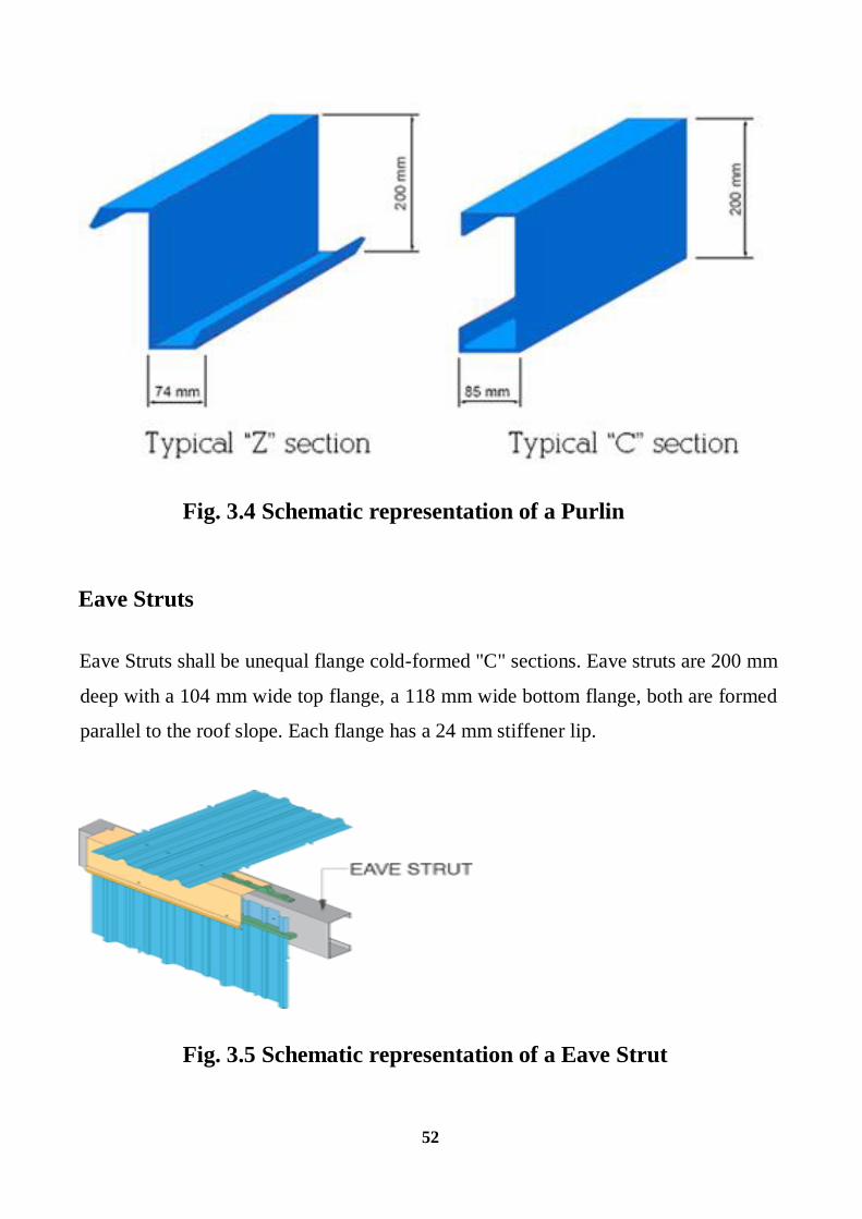
52
Fig. 3.4 Schematic representation of a Purlin
Eave Struts
Eave Struts shall be unequal flange cold-formed "C" sections. Eave struts are 200 mm
deep with a 104 mm wide top flange, a 118 mm wide bottom flange, both are formed
parallel to the roof slope. Each flange has a 24 mm stiffener lip.
Fig. 3.5 Schematic representation of a Eave Strut

53
Bracings:
The Cable bracing is a primary member that ensures the stability of the building against
forces in the longitudinal direction such as wind, cranes, and earthquakes.
Diagonal bracing in the roof and sidewalls shall be used to remove longitudinal loads
(wind, crane, etc.) from the structure. This bracing will be furnished to length and
equipped with bevel washers and nuts at each end. It may consist of rods threaded each
end or galvanized cable with suitable threaded end anchors [6]
3.2.3 SHEETING OR CLADDING:
The sheets used in the construction of pre- engineered buildings are composed of the
following:
Base metal of either Galvalume coated steel .Galvalume coating is 55% Aluminium
and about 45% Zinc by weight. An exterior surface coating on painted sheets of 25
microns of epoxy primer with a highly durable polyester finish.
An interior surface coating on painted sheets of 12 microns of epoxy primer and
modified polyester or foam. The sheeting material is cold-rolled steel, high tensile 550
MPA yield stress, with hot dip metallic coating of Galvalume sheet.
Fig. 3.6 Schematic representation of a GI Sheets

54
3.2.4 ACCESSORIES
Anchor bolts:
Bolts used to anchor the structural members to the concrete floor, foundation or other
support. This usually refers to the bolts at the bottom of all columns. Anchor bolts are
Anchor bolts are manufactured with circular steel rods having threading portion at the
top for bolting and bent up at the bottom for Foundation.
Fig. 3.7 Schematic representation of an Anchor Bolts
Turbo ventilators
A Turbo Ventilator is a free spinning roof ventilator that works on free wind energy.
When there is a difference in thermal or wind pressure between the inside and outside
of the building, the air is forced to move through the opening of the Turbo Ventilator
in order to maintain an equilibrium condition. The benefits of using turbo ventilators
Are that it improves air circulation and cuts off the suffocation. Eco friendly turbo
ventilator involves no operating cost, are free from maintenance and are has trouble
free operations.

55
Fig. 3.8 Schematic representation of an Air Vents
Sky lights (or) wall lights:
Sky lights may consists of poly carbonate sheets which is translucent sheet that allows
maximum light and minimum heat. High strength translucent panels are glass fiber
reinforced polyester, high strength and may be either and it provides with an estimated
light transmitting capacity of 60%. High strength translucent panels match standard
panel profiles, are 1/16 thick, weigh 8 ounces per square foot, and are white with a
granitized top surface.
Insulated translucent panels are available in type 1, "R" panel and standing seam profiles
only.
Damper, Standard size is 3000 mm long with a throat opening of 300 mm.
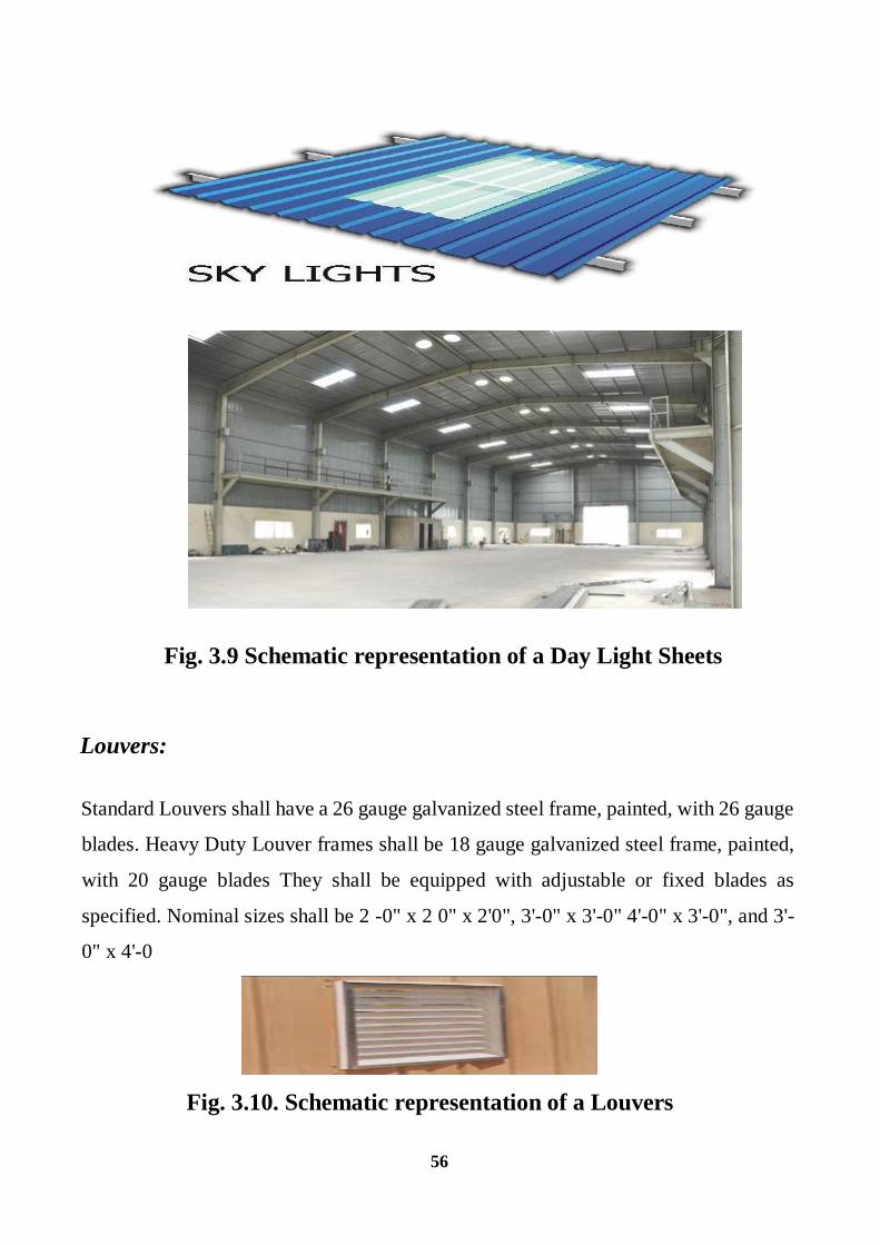
56
Fig. 3.9 Schematic representation of a Day Light Sheets
Louvers:
Standard Louvers shall have a 26 gauge galvanized steel frame, painted, with 26 gauge
blades. Heavy Duty Louver frames shall be 18 gauge galvanized steel frame, painted,
with 20 gauge blades They shall be equipped with adjustable or fixed blades as
specified. Nominal sizes shall be 2 -0" x 2 0" x 2'0", 3'-0" x 3'-0" 4'-0" x 3'-0", and 3'-
0" x 4'-0
Fig. 3.10. Schematic representation of a Louvers

57
Walking doors:
Walk doors are generally 915 mm or 1830 mm wide x 2134 mm high made of 20 gauge
electro galvanised steel with a core of polyurethane insulation. Door fixture is provided.
[6]
Aluminium windows:
Designed for installation with wall panel, double slide, self -flashing with pre-glazed
clear glass and removable half insect screen. Standard size is 1 m x 1 m. multiple
windows can be formed by joining the jamb fins together
Fasteners:
Standard fasteners shall be self -drilling screws with metal and neoprene washers. All
screws shall have hex heads and are zinc plated.

58
3.3 FLOWCHART OF METHODOLOGY CARRIED OUT
`
Assuming Dimensions, Structural Conditions
and Cross Sections
Structural Analysis
Selection Of cross Sections to satisfy Structural
requirements, performance
On Violating Initial
assumptions
On satisfying
Initial assumptions
Final design
Design of Column
Design of Rafter
Design of Purlin
Foundation
Design of Connection

59
CHAPTER 4
DESIGN OF PRE-ENGINEERED STEEL BUILDING
4.1 GENERAL
Pre-engineering of metal buildings can be optimized to meet specific design criteria.
Largely Indian and American practice of design is followed by most of the consultants
and PEB vendors in India these days. A brief of design codes used in each of these is
attached herewith:
The main framing of PEB systems is analysed by the stiffness matrix method. The
design is based on allowable stress design (ASD) as per the American institute of Steel
Construction specification or the IS 800. the design program provides an economic and
efficient design of the main frames and allows the user to utilize the program in
different modes to produce the frame design geometry and loading and the desired load
combinations as specified by the building code opted by the user. The program operates
through the maximum number of cycles specified to arrive at an acceptable design.
The program uses the stiffness matrix method to arrive at an acceptable design. The
program uses the stiffness matrix method to arrive at the solution of displacements and
forces. The strain energy method is adopted to calculate the fixed end moments,
stiffness and carry over factors. Numerical integration is used.
4.1.1 DESIGN CYCLE
The design cycle consists of the following steps:
1. Set up section sizes and brace locations based on the geometry and loading specified
for the frame design.
2. Calculate moment, shear, and axial force at each analysis point for each load
combination.

60
3. Compute allowable shear, allowable axial and allowable bending stress in
compression and tension at each analysis point.
4. Compute the corresponding stress ratios for shear, axial and bending based on the
actual and allowable stresses and calculate the combined stress ratios.
5. Design the optimum splice location and check to see whether the predicted sizes
confirm to manufacturing constraints.
6. Using the web optimization mode, arrive at the optimum web depths for the next cycle
and update the member data file.
7. At the end of all design cycles, an analysis is run to achieve flange brace optimization.
[16]
Frame Geometry:
The program has the capability to handle different types of frame geometry as follows
Frames of different types viz. rigid frames, frames with multiple internal columns,
single slope frames, lean to frames etc; Frames with varying spans, varying heights and
varying slopes etc. Frames with different types of supports viz. pinned supports, fixed
supports, sinking supports, supports with some degrees of freedom released.
Unsymmetrical frames with off centric, unequal modules, varying slopes etc. User
specified purlin and girt spacing and flange brace location.
Frame Loading:
Frame design can handle different types of loadings as described below:
All the building dead loads due to sheeting, purlins, etc. and the self- weight of the frame
and Imposed live load on the frame with tributary reductions as well.
Wind loads input such as basic wind speed or basic wind pressure that will be converted
to deign wind pressure as per the building code specified by the user and shall be
applied to the different members of the building according to the coefficients
mentioned in the codes prescribed by the user. The standard building codes like
61
MBMA, UBC, ANSI, IS: 875 parts 3 etc. are used for this purpose. Crane and non-
crane loading can be specified by the user and the program has the capability to handle
these special loads and combine them with the other loads as required.
Seismic loads corresponding to the different zone categories of various international
codes can also be defined and combined with other load cases as required. Temperature
loads can also be specified in the form of different differential temperature value on
centigrade and specifying the appropriate coefficient for the thermal expansion. Load
combinations with appropriate load factors can be specified by the user as desired.
4.2 Design of a warehouse
The majority of warehouse buildings are made out of steel for obvious reasons of high
strength/weight ratio. A study, on the Efficient Design of Large span
hangars/structures, is presented. A clear span of gable frame of 15 m is adopted and
the designs of Components are discussed below as follows
Structure with Span larger than 40 m can be regarded as long span structures and need
to be carefully designed keeping a balance of all the aspects like its weight, deflections
(sway) and foundation forces. There are many combinations of designing large spans,
like conventional truss & RCC column combination, truss & steel columns, Pre-
engineered building (PEB) etc.
These days with the concept of PEB, the major advantage we get is the use of high
strength steel plates (usually Fe 350), lighter but high strength cold form purlins, and
550 Map Galvalume profiled sheets. The use of PEB not only reduces the weight of
the structure because high tensile steel grades are used but also ensures quality control
of the structure. In the following study, we have designed a warehouse using this
modern concept of PEB. [16]

62
4.2.1 DESIGN PROCESS AND PRINCIPLES
Loads on Structure
The determination of the loads acting on a structure is a complex problem. The nature
of the loads varies essentially with the architectural design, the materials, and the
location of the structure. Loading conditions on the same structure may change from
time to time, or may change rapidly with time.
Dead load:
Dead loads shall cover unit weight/mass of materials, and parts or components in a
building that apply to the determination of the dead loads in the design of buildings
and shall be considered as per IS: 875 (Part 1) - 1987 according to the densities of the
possible components. This includes main frames, purlins, girt, cladding, bracing and
connections etc.
Live Load:
Imposed loads shall be considered as per IS: 875 (Part 2) 1987. Live load shall be
considered as 2.675 KN/m for the analysis and design.
Wind Load:
The basic wind speed and design velocity which shall be modified shall be taken
As per IS: 875 (Part 3) 1987.
As though this warehouse building is located within the area surrounded by high rise
apartments and buildings action of wind load is neglected as even the eave height is
limited only to 6m wind load is not considered.

63
4.2.2 DESIGN CODES
Following are the main design codes generally used:
AISC: American institute of steel construction manual
AISI: American iron and steel institute specifications
MBMA: Metal building manufacturer s code
ANSI: American national standards institute specifications
ASCE: American society of civil engineers
UBC: Uniform building code
IS: Indian standards (IS1893-2002 PART 1 FOR EQ) and (IS 875 PARTIII FOR
WIND)
4.3 DIMENSIONS OF THE WAREHOUSE
Width = 60 meters
Length = 15 Meters
Eave Height = 6 Meters
Bay Spacing = 6 Meters
Brick work = 2 Meters
Rise = 2m
Slope = 14.93 degree

64
Fig. 4.1 PLAN OF THE BUILDING

65
Fig. 4.2 ELEVATION OF THE BUILDING
Fig. 4.3.3 SIDE WALL ELEVATION OF THE BUILDING

66
4.4 DIMENSION OF ROOF
Area = 15 m 60 m
Span (l) = 15m
Rise (h) = 2m
Slope of the roof = tan-1 ( 2
7.5) = 14.930
= 14.930
Thus inclination of roof with horizontal = 14.930
4.4.1 Length of the rafter: (lr)
Lr = (height of the column) 2 + (rise) 2
Lr = (6)2 + (2)2
Lr = 7.76m
Actual length of the sheeting is likely more than this to cover eave girder
4.4.2 Number of purlins
Maximum allowable purlin spacing = 1400mm
Approximate number of purlin = 7762
1400
= 5.54 no’s
Place 6 number of purlin on each rafter @ 1290mm c/c
Spacing of purlins = 1.29 m

67
4.4.3 Loading calculation
4.4.4 Dead load:
Roofing material – GI sheeting with unit weight of 150 N/m2
Assuming unit weight of purlin as 100 N/m2
Total dead load = 150 + 100
= 250 N/m2
= 0.250 KN/m2
Dead load on plan area
= load bay spacing
= 0.25 6
= 1.5 KN/m
4.4.5 Live load:
As per IS 875 part 2 when slope is greater than or equal to 10 (i.e.) 10 then the
imposed load on the purlin is 750 N/m2 for every degree increase in slope in excess of
10 degree but not less than 400 N/m2
Live load = 750 -20 [14.93-10] = 651 N/m2
= 651 N/m2
2
3 rd. Load = 2
3 651 KN/m2
= 434.2 KN/m2
Live load on the plan area
= 434.2 6
= 0.4342 103
= 2.605 KN/m

68

69
4.5 DESIGN OF PURLINS
Span = 14 m
Length of the continuous purlin = 6 m
Spacing of purlin = 1290 mm
Slope of the roof = 14.93
The purlin is subjected to biaxial bending moment and as to design for different load
combinations and here as we exclude wind load only under live load and dead load
combination is designed
The following are the loads;
Wd = 1 KN
WL = 1.62 KN
And the components along the principal axes of the purlin are:
4.5.1 Dead load
Wdy = Wd cos
= 1 cos (14.93)
= 0.966 KN
Wdy = Wd sin
= 0.2574 KN
4.5.2 Live load
Wly = Wl cos
= 1.l2 cos (14.93)
= 1.566 KN
Wlx = wl sin
= 0.417 KN
The load combinations considered is D.L + L.L
The design bending moments are computed assuming that the purlins are continuous
and the maximum (absolute) bending moment occurs at the support.

70
4.5.3 Load Case: D.L + L.L
Mx1 = [10
DYW B +9
LYW B ]
= 0.966 1.566[ ] 6
10 9
= (0.9066 + 0.174) 6
Mx1 = 1.6236 KNm
My1 = [10
lYW B +9
WlxB ]
= 0.966 0.414[ ] 6
10 9
= (0.9066 + 0.046) 6
My1 = 0.8576 KNm
With these bending moment values on trying ISMC 75
Whose properties are Zx = 20.3cm3, Zy = 4.7 cm3
1 1MX MY
Zx Zy
1.62 0.85
20.3 4.7 KN/m2
Here = 180.85 N/m2
Here the stress is greater than the permissible stress
Hence not safe
Thus on trying ISMC 150
Zx = 103.9 103 mm, Zy = 9 103 mm
1 1MX MY
Zx Zy
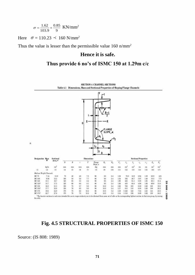
71
1.62 0.85
103.9 9 KN/mm2
Here = 110.23 160 N/mm2
Thus the value is lesser than the permissible value 160 n/mm2
Hence it is safe.
Thus provide 6 no’s of ISMC 150 at 1.29m c/c
Fig. 4.5 STRUCTURAL PROPERTIES OF ISMC 150
Source: (IS 808: 1989)

72
4.6 DESIGN OF STEEL RAFTER
4.6.1 Total load
Dead load from sheeting = 150 N/m2
Self-weight of purlin = 100 N/m2
Total dead load = 250 N/m2
Spacing of purlins = 1.29 m
Dead load on each purlin = 0.250 1.29
Total dead load = 0.3225 KN/m
Factored dead load = 1.5 0.3225 = 0.4837 KN/m
Live load = 2.6052 KN/m
Factored live load = 1.5 0.26052 = 3.9078 KN/m
Total working load = 1.5 6 = 9 KN/m
Total factored load = 1.5 9 = 13.5 KN/m
LENGTH OF RAFTER (L) =7.76 m
Design moment M = 2
8
Wl
M = 1.6875 7.762
M = 101.67 KNm
Design shear V = 2
Wl
V = 6.75 7.76
V = 52.38 KN
Section modulus required = M
Fy ym0
Z p =
101.67
250 1.1 10 6
Zp = 447.348 10 3 mm3
On trying ISMB 400 which has Section modulus of Zp= 1176.168 10 3 mm3.

73
4.6.2 Properties of the section:
Depth of the section h = 400 mm
Width of the flange b = 140mm
Section area a = 7845.58mm2
Thickness of the flange tf = 16mm
Thickness of the web tw = 8.9 mm
Depth of web d = h-2 (h/2) = 400 – 2 (32.8)
= 333.4 mm
Moment of inertia about Z – Z axis
IZZ = 20438.4 10 4 mm4
Elastic section modulus
Ze = 1022.7 10 3 mm4
Outstanding leg of compression flange
B = 140 /2 = 70
4.6.3 SECTION CLASSIFICATION
= (250 /fy)1/2 = (250 /250 )1/2 = 1
B/Tf = 70 /16 = 4.38 9.5
D/TW = 333.4 /8.9 = 37.57 84
Hence the section is classified as plastic section
4.6.4 CHECK FOR SHEAR STRENGTH
Design shear
V = 27.37 KN
Design shear strength of the section,

74
13
1.1
13
1.1
250400 8.9
13
1.1
467728
467.128 27.37
D
D W
D
D
D
y
y
V area
V
f
fh T
V
V N
V
Hence It Is Safe
4.6.5 Check for Moment Capacity
D/TW = 38.2 WHICH IS LESS THAN 67 , SINCE =1
Hence,
Md =
13
1.1
13
1.1
250400 8.9
13
1.1
467728
467.128 27.37
W
y
y
are
h
N
fa
fT
p = 1.1 since plastic section
Md = 1.0 1176.163 103
250 /1.1 1.2 1022.7 103250 /1.1
= 267 .310 10 6 278 .918 106
Md = 267.310 106 N-mm
Check for deflection, total working load = 12.8 4.5 = 17.3 N/mm

75
4.6.6 Check for deflection
45
384
wl
EI
4
4
5 17.3(8300)
2 105 20458.4 10
27.127mm
Permissible deflection for a beam in building
= Le/300
= 8300 / 300
= 27.67 mm
Hence the deflection is within the permissible limits
Hence it is Safe
Provide ISMB 400
TOTAL WORKING LOAD = L.L + D.L
= 12.8 4.5
= 17.3 N/mm
MINIMUM DEFLECTION =
4
5 4
6.903×7.43 5δ=
2×20458.4×10 ×10 584
20.127mm
Le/300 = 27.76 ,6
20.127 27.67
Hence it is safe
Thus provide ISMB 400 604.3 N/m

76
4.7 Design of Column
4.7.1 Design stress
2
6
= factored load + factored live load + self weight of the beam
= 0.4837 + 3.96 + 0.604
= 4.9877 6
= 29.92 KN
125
NUse ISMB 400 @ 604.3
m
Area P
Column m
Load
Nfcd
mm
2rovided = 7846 mm.
Width of the Flange = 140 mm
Selecting 20 mm Plates , breadth required ' b ' is obtained from
2b ×t = 7846
7846 2b =
2
0
b = 196.15 mm
b; 200 mm
Thus provide 20mm × 200mm plates
Check for Over Hang :
140 Over Hang = 200 - = 3 p 12 t
20
Total Area Provided :
A = 7846 + 200 + 20 × 2
2 A = 15846 mm.

77
NFor ISMB 400 @ 604.3
m
4 4Izz = 2045.4 × 10 mm
2Iyy = 15846 mm
For the section selected
d t 2Izz = Izz + 2bt ( + )2 2
4 2Izz = 301.384 × 10 + 2 × 200 × 20 (100 + 10 )
6 4Izz = 301.384 × 10 mm

78

79

80
Fig. 4.6 BEARING TYPE OF CONNECTIONS

81

82

83
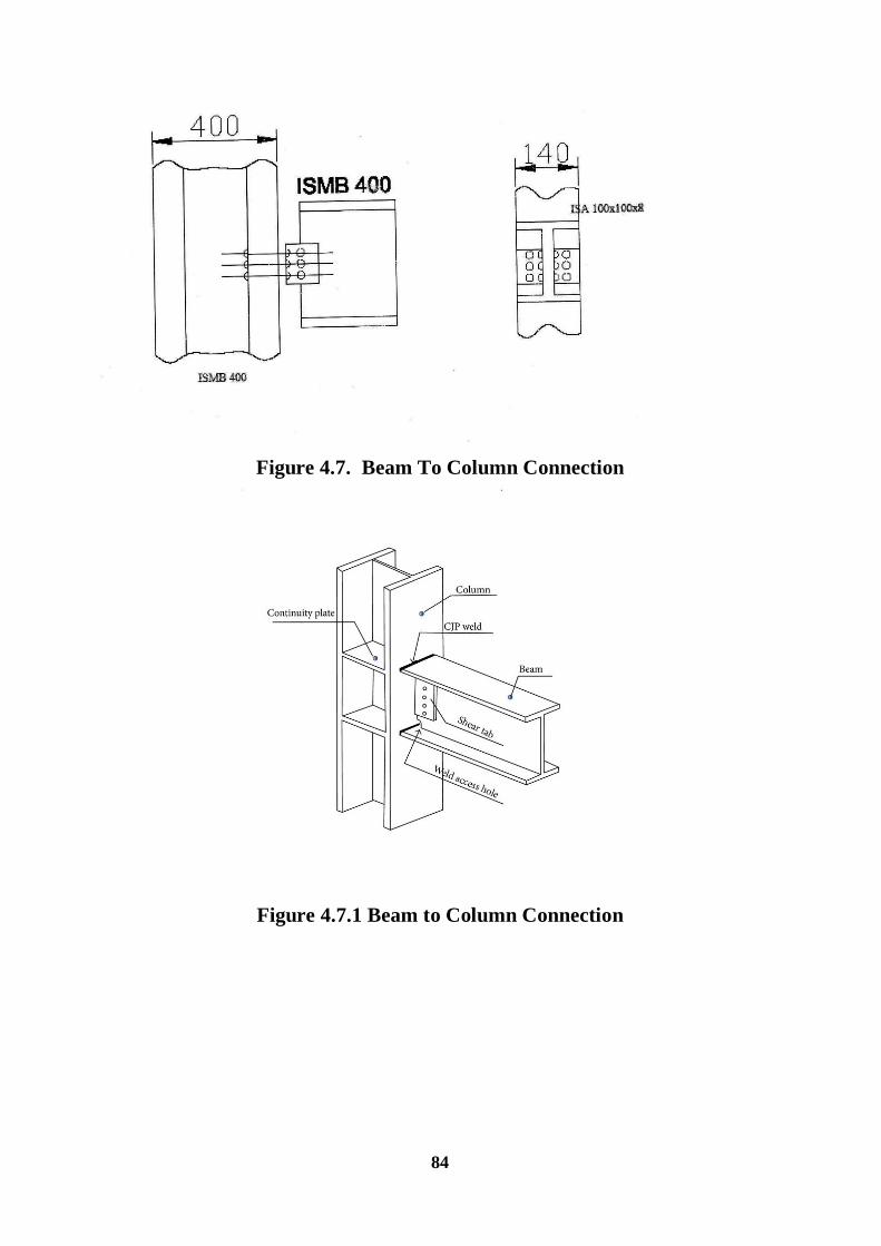
84
Figure 4.7. Beam To Column Connection
Figure 4.7.1 Beam to Column Connection

85
CHAPTER 5
ANALYSIS USING STAAD PRO
Fig. 5.1 Gable frame
Fig. 5.1 Cross Section of the Structure

86
Fig. 5.3 Displacement
Fig. 5.4 Displacement

87
Fig. 5.5 bending moment
Fig. 5.6 live load

88
Fig. 5.7 Dead load

89
Fig. 5.8 Sectional Properties of ISMB 400

90
CHAPTER 6
CONCLUSION
6.1 GENERAL:
Using of PEB instead of CSB may be reducing the steel quantity and thus reducing
the construction cost and Reduction in the steel quantity definitely reducing the dead
load. Reduction in the dead load reducing the size of Foundation. And reduction is all
but not the performance and life span is the unique property of pre- Engineered and
using PEB increase the Aesthetic view of structure
All the result values obtained on analyzing in this project proves to be economical and
the performance delivered by the pre – engineered building is higher than that of
conventional steel building and the results are as follows
6.2 Results:
Thus for the under taken project on pre-engineered building the results of the
components that were designed are as follows:
1. Roof Design : For The Area Of The Roof (A = 900mm2) Provide 6 No’s of
Purlin @ 1290mm C/C [4.4]
2. Purlin Design : Provide 6 No’s of ISMC 150 @ 1290 mm C/C [4.5]
3. Rafter Design : Provide ISMB 400 604.3 N/M [4.6]
4. Column Design : Provide ISMB 400 604.3 N/M With 20 200 mm Plates
[4.7]
5. Design Of Connections : Provide 12 No’s Of 20mm Diameter Bolts With The
Pitch Of 40 mm In Four Rows [4.8]
6. Design Of Gusset Plate : Provide ISA 125 95 [4.9]
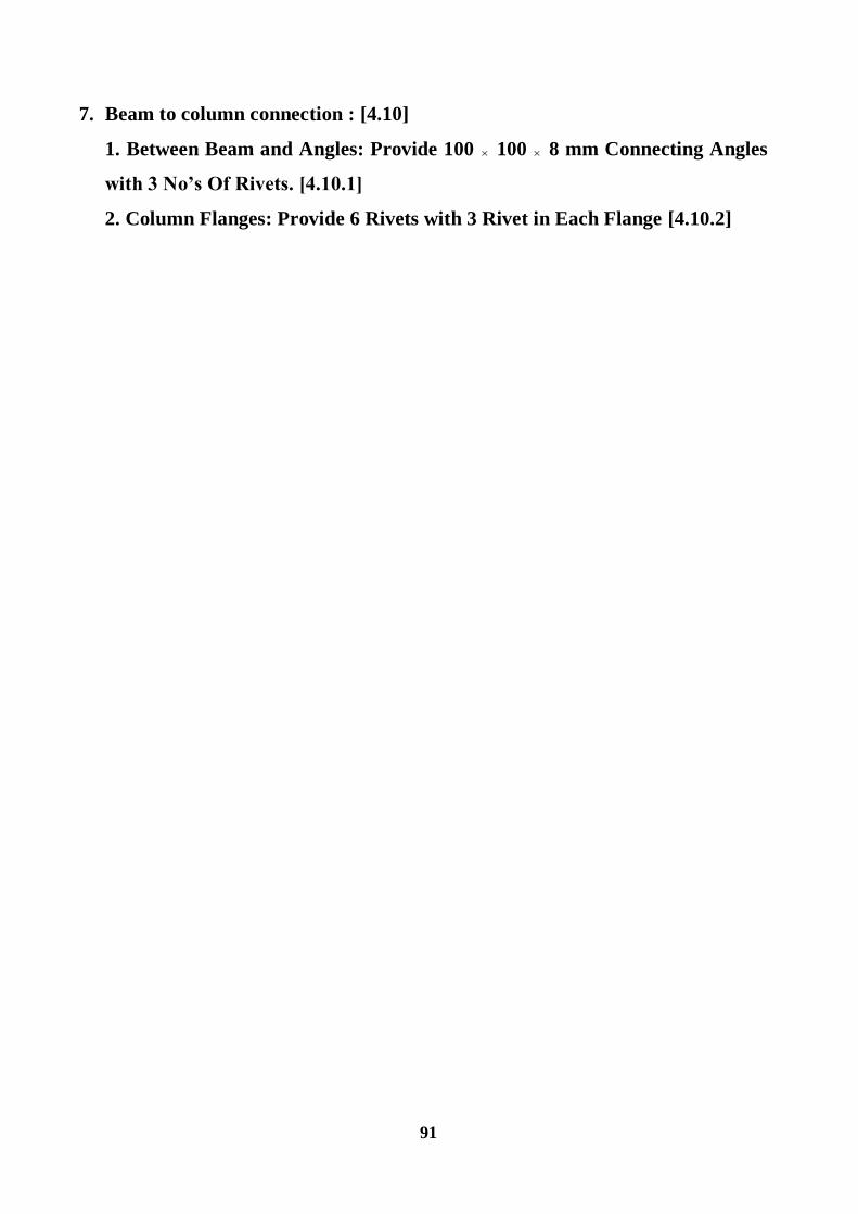
91
7. Beam to column connection : [4.10]
1. Between Beam and Angles: Provide 100 100 8 mm Connecting Angles
with 3 No’s Of Rivets. [4.10.1]
2. Column Flanges: Provide 6 Rivets with 3 Rivet in Each Flange [4.10.2]
92
REFERENCE:
[1]. Aijaz Ahmad Zende, Prof. A. V. Kulkarni, Aslam Hutagi (Feb 2013).
Comparative Study of Analysis and Design of Pre-Engineered- Buildings and
Conventional Frames. IOSR Journal of Mechanical and Civil Engineering,
Volume 5, Issue.
[2]. C. M. Meera (June 2013). Pre-engineered building design of an industrial
warehouse. International journal of engineering sciences & emerging technologies.
Volume 5 Issue 2, pp: 75-82 Dr. Ramachandra & Virendra Gehlot “Design of Steel
Structures”
[3]. Design Concept of Pre-engineered Building by Syed Firoz1, Sarath Chandra
Kumar B1, and Design concept of pre-engineered building. International journal of
engineering research & applications, volume 2, issue 2, pp: 267-272
[4]. Design of Long span structures and Hangars by Amit Bharana ERA buildings
ltd.
[5] G. Sai Kiran, A. Kailasa Rao, R. Pradeep Kumar (Aug 2014). Comparison of
Design Procedures for Pre Engineering Buildings (PEB): A Case Study.
International Journal of Civil, Architectural, Structural & Contruction Engineering,
Volume 8, No. 4
[6]. http://www.engineeringcivil.com/pre-engineered-buildings.html
[7]. http://nbmcw.com/articles/PEB -roofing/PEB -prefab-steel-structures/18161-
preengineered-building-systems-a-promising-future.html
[8]. http://nbmcw.com/articles/PEB -roofing/PEB -prefab-steel-structures/18161-
preengineered-building-systems-a-promising-future.html

93
[9]. Introduction to Pre-engineered Steel Buildings
http://www.engineeringcivil.com/preengineered-buildings.html
[10]. IS: 800-2007: General Construction in Steel - Code of practice
[11]. IS: 875 (Part 1): - 1987 Code of Practice for Design Loads
[12]. IS: 875 (Part 2): - 1987 Code of Practice for Design Loads
[13]. IS: 875 (Part 3): - 1987 Code of Practice for Design Loads
[14]. Jatin D. Thakar, 2 Prof. P.G. Patel. Comparative study of pre- engineered
steel structure by varying width of structure. International journal of advanced
engineering technology, volume 4, issue3
[15]. N. Subramanian (2010) “Design of Steel Structures”
[16]. P. Dayaratnam “Design of Steel Structures”
[17]. Pre-engineered Metal Buildings < The Latest Trend in Building
Construction. By.K. Mitra Llyods Insulations Limited.12.
[18]. PEB VS Conventional the Zamil Steel Limited
[19]. S.S. Bhavikatti “Design of Steel Structures”
[20]. S. Ramamrutham “Design of Steel Structures”