pre-feasibility report for exploratory drilling...
TRANSCRIPT

Pre-Feasibility Report
for
Exploratory Drilling Operation
at
Cambay Basin
Block: CB-ONN-2010/5
Prepared for
Pan India Consultants Pvt. Ltd. (PICPL)
and
Frost International Limited (FIL)
Prepared By
SGS India Pvt. Ltd.
August 2014

SGS INDIA PVT LTD i
Table of Contents
EXECUTIVE SUMMARY ............................................................................... i
CHAPTER 1: INTRODUCTION .................................................................... 1
1.1 Background and Introduction ....................................................................................1
1.2 Cambay Basin: CB-ONN-2010 .................................................................................1
1.3 Location of Block ......................................................................................................2
1.4 Identification of Project and Project Proponent .........................................................4
CHAPTER 2: PROJECT DESCRIPTION ...................................................... 5
2.1 Brief Description and Nature of Project .....................................................................5
2.2 Site Analysis .............................................................................................................6
2.3 Exploratory Drilling of Wells ......................................................................................6
2.4 Seismic Survey ......................................................................................................14
2.5 Proposed Infrastructure ..........................................................................................21
CHAPTER 3: REHABILITATION AND RESETTLEMENT (R&R) PLAN ..... 22
3.1 Rehabilitation and Resettlement (R&R) Plan ..........................................................22
CHAPTER 4: PROJECT SCHEDULE AND COST ESTIMATES .................. 23
4.1 Project Schedule and Cost Estimates.....................................................................23
CHAPTER 5: ANALYSIS OF PROPOSAL .................................................. 24
5.1 Analysis of Proposal (Final Recommendations) .....................................................24
SGS INDIA PVT LTD i
EXECUTIVE SUMMARY
Introduction
Government of India has awarded Exploration Block CB-ONN-2010/5 in the Cambay Basin
having surface coverage of 49 sq. km situated in Patan and Mehsana districts of Gujarat to
consortium of Pan India Consultants Pvt. Ltd. (PICPL) with participating interest of 20% and
Frost International Limited (FIL) with participation interest of 80% and signed a Production
Sharing Contract (PSC) in NELP-IX round for the same. Pan India Consultants Pvt. Ltd.
(PICPL) is the operator of the block.
In addition to the Production sharing contract signed with MOPNG, Government of India, a
Petroleum Exploration License (PEL) has also been granted by Ministry of Energy and
Petrochemicals, Government of Gujarat vide their order no. PEL-10-2012-964-E dated
15.03.2013 valid for 4 years, for exploration of Oil & gas in this block as per the PSC signed
with the Government of India.
Block Location
The Block CB-ONN-2010/5 lies in the Ahmedabad-Mehsana Tectonic block of the Cambay
Basin. The block falls in the northern part of the Ahmedabad-Mehsana tectonic block, having
a number oil and gas fields, of which the prominent ones are Kalol, Jotana, Sobhasan,
Becharaji and Balol. Lanwa and south Patan fields are located to the southeast and
northwest respectively of the block. The block is extensively covered by 2D Seismic lines and
also by 3D seismic data. The 2D seismic data is of various vintage and the 3D data was
acquired in 2007.
The site is well connected from both Mehsana and Patan district. Mehsana ~ 17 km (NE) and
Patan 12 km (N) from Block boundary. The nearest railway station is Chanasma at less than
one kilometre from the north-west corner of the block while Mehsana is at a distance of 17
kms. The nearest airport is Sardar Valabhbhai Patel in Ahmedabad which is about 75 kms
from the NE corner of the boundary.
Exploratory Drilling
Drilling Site and Rig
Approximately 1.2 hect. (120 m x100 m) land in total would be required for exploration drilling
of each well. A standard electric onshore rig of 1000-1200BHP with Rotary/Top drive System
shall be used.

SGS INDIA PVT LTD ii
Drilling Fluids (Mud)
The role of the drilling fluid (mud) in pressure control is especially important. If the drill bit
penetrates a formation containing oil, gas or water under pressure, these fluids are
prevented from flowing into the borehole by ensuring that the drilling mud is of sufficient
density to the natural formation pressures. The density of the mud can be increased by the
addition of barite weighting material. Bentonite is employed to improve the theological
properties and enable the drill cuttings to be transported from the hole while drilling and also
be suspended in the fluid while the drill bit is being changed. The barite used in the drilling
mud would be as per API standard specifications.
Drilling Fluids (Mud)
Based on geological prognosis and predicted formation pressures, Water Based Mud (WBM)
will be used for all the wells considering environmental constraints and hazards. The main
components of drilling mud are slurry of inert solids suspended in a liquid phase. The main
constituents of the WBM are bentonite and barites, both of which are natural minerals. In
case if the WBM is not able to be used due to geological formation complexities then low
toxic oil base mud with less than 1% aromatic contents can be used after intimating the
MOEF and/or State Pollution Board.
The drilling fluids left over at the end of the particular well will be discharged into the lined
waste pits and dried. The pits will be provided with plastic liners to maintain integrity and
prevent any leakage. The drill cuttings cut by the bit are removed from the mud by the shale
shakers and other solids removal equipment and transferred to the waste pits. Once the
mud is cleaned it is pumped down the drill string again.
Drill Cutting
The drill cuttings, cut by the bit, shall be removed from the mud by the shale shakers and
centrifuges and transferred to the mud tank. Once the mud shall be cleaned, it is pumped
down the drill string again. The drilling fluid will be re-used after extraction of drill cuttings and
necessary treatment. It is estimated that around 700-800MT of drill cuttings will be generated
as waste, which will be stored in a impervious pit with liner at the site and the pit will be
covered or treated as per waste disposal guidelines for such wastes. At the end of drilling of
each well, dried cuttings will be disposed off in secured landfill site (pit).
i) Drill-stem testing
If the geologist detects the presence of oil or gas in the drill cuttings, a drill-stem test is
frequently performed to evaluate the formation or zone from which the oil show was
observed. Drill-stem tests may also be performed when the driller observes a decrease in the
time required to drill a foot of rock, known as a "drilling break."
SGS INDIA PVT LTD iii
ii) Surface Testing &Flaring
In case hydrocarbons are detected in the well, the quantity and quality will be tested. The
fluids & gases coming out from the well will be flared. The flaring will be intermittent and last
only for few days and it will not pollute environment. However, for flaring all the flaring
guidelines for onshore wells will be followed and the design, size and location of flaring stack
will be decided based on surrounding habitations and the flaring guidelines.
iii) Well logging
Drilling operations continue until the predetermined total depth of the well is reached. The
drill string is removed from the well bore to allow the insertion of logging tools, which are
lowered all the way to the bottom of the hole by means of a special cable. This cable
contains numerous electrical circuits. Signals detected by the tools are recorded in a
recording truck at the surface by means of the electrical circuits contained in the cable.
iv) Completing the well
When drill-stem testing and well-logging operations have been completed and the results
have been analyzed, the company management will decide whether to complete the well as
a producing well or to plug it as a dry hole.
v) Restoration of Cutting Containment Area
At the conclusion of well testing at each drilling site, solar drying will dewater the waste pits.
All residual solids and liner will be covered with thick column of native soil. The cutting mud is
inert and with HDPE (High Density Poly-ethylene) linings of the pit in place it will not pose
any scope of environmental hazard.
vi) Drilling Schedule
Total estimated time required for drilling of one well will be about 90-120 Days and testing
period of 15-20 days.
vii) Restoration of Drilling Site
In the event that appraisal drilling is unsuccessful at any particular site then the site will be
cordoned off to avoid any accidents.
viii) Power Requirement
The power requirement for the drill rig will be met by four (04) x 500 KVA DG sets to operate
the drill rig. During test flaring, only one DG set shall be in operation to meet the power
requirement. The power requirement for the campsite will be catered through one Diesel
Generators (DG) sets of 100 KVA.
SGS INDIA PVT LTD iv
ix) Water Requirement
The water requirements for the drilling and domestic purposes at drill site will be to the order
of 20 kilolitres per day (KLD). The camp will normally operate with around 40 personnel and
will consume water @ 5 KLD for domestic purpose only. Water requirement will be met from
nearby local sources.
x) Fuel Requirements & Storage
Estimated consumption of HSD shall be about 4-5 KL for entire operation and majority of it
will be used drilling rig and will be stored temporarily in 200 lit drums at the drilling site.
xi) Air Emissions & Noise
Sources of air emissions and noise will be limited to generators, well test flaring, vehicles etc
during the proposed project activities. By careful design of well test flaring and regular
maintenance of all vehicles and other machines shall keep air emissions and noise to a
minimum. Average cumulative noise from DG sets and drilling equipment will be in the range
of ~ 70 to 80 dB.
xii) Waste Disposal
Conduits will be laid to collect wastewater from kitchens, toilets, bathing and washing areas.
Wastewater from toilets shall be sent to soak pit after passing through Septic tank while
same from other sources shall be sent to soak pit for final disposal. On completion of the
exploration activities, all the installations will be removed without leaving debris. Kitchen
waste will be dumped in humus pit for its future use as manure. Other solid wastes such as
plastics, metals, and workshop waste will be removed by a contracting agent. All used oil and
anything mechanically reusable will be provided free to local gasoline stations for use as
seconds. Hazardous materials, such as batteries and aerosols will be placed in a separate
container, appropriately marked, and disposed of as per relevant guidelines. Medical waste
will be bagged and binned in a separate container appropriately labelled. This waste will be
disposed of either at a local hospital or as per guidelines for disposal of medical waste.
The waste and spent mud generated from drilling of wells would be collected in a lined pit
and impervious sheeting will be underlined for all the chemical storage areas. The waste
water to be generated during drilling activities will be collected in a pit lined with HDPE to
prevent seepage. The mud components during the storage form a bentonite (clay) lining
along the pit wall preventing the seepage of water to the underground strata. Any
hydrocarbon contamination will be skimmed off from site before proceeding to the next site.
This would ensure that no leaching or subsurface contamination finally reaches the
groundwater table.

SGS INDIA PVT LTD v
Drill cuttings which are inert materials of shale, sand, and clay fall into the lined waste pits.
The drilling fluids left over at the end of the particular well will be discharged into the lined
waste pits and dried. The drill cuttings cut by the bit are removed from the mud by the shale
shakers and other solids removal equipment and transferred to the waste pits.
Seismic Survey
Method of Seismic Survey
In the proposed programme, Seismic survey will be done in case there are no sufficient
hydrocarbons encountered in the drilling of 02 wells. The seismic survey project involves
topographic surveying, shot hole drilling, laying the cables and geophones on pre-decided
geometry, generating seismic energy and recording the seismic energy.
i) Demobilization and Site Restoration
Once the survey and recording are finished, equipment will be removed and personnel will
leave the site. The site will also be restored to its original state by filling and burying all holes
as well as collecting all wastes and materials out of the site. It is expected to take
approximately one month to complete the site restoration including recording public
complaints, if any.
ii) Access to the Survey Zone
Where no existing roads or tracks exist, the seismic will be man-portable. In this case only
foot-paths wide enough for one person carrying equipment to pass will be cleared for access
and no mature trees will be cut.
Water Requirements
The water requirement for the survey team and the domestic needs of the temporary
residential camp will be to the order of around 7-8 kilolitres per day (KLD). The camp will
normally operate with 40 personnel. Potable water shall be provided for drinking purposes
while water for other usages shall be provided from local sources.
Power Requirement
The power requirement for the campsite will be catered through Diesel Generator (DG) sets to
be temporarily stationed at the campsite. The rated capacity of each of the 2-DG sets for the
campsite will be in the order of 50 KVA.
Waste Disposal
Conduits will be laid to collect wastewater from kitchens, toilets, bathing and washing areas.
Wastewater from toilets shall be sent to soak pit after passing through Septic tank while
same from other sources shall be sent to soak pit for final disposal.

SGS INDIA PVT LTD vi
Emissions and Noise
Sources of air emissions will be limited to generators and vehicles. The main camp will
include an area reserved and properly equipped for the maintenance of vehicles and other
machines. Regular maintenance of all project vehicles and other machines should keep air
emissions and noise to a minimum. In critical habitats, if road access exists, noise from
vehicles will be minimized by speed restrictions.
Timing of Seismic Survey Activity
Surveying, shot hole drilling and recording operations are expected to commence after
analysis of findings of proposed exploratory drilling of two (2) wells and would be completed
within a period of 2-3 months.
Rehabilitation and Resettlement
No permanent acquisition of land for the project. The area required for drilling operation will
be temporarily taken on lease for few months and if there is discovery of Oil or Gas then it will
be converted in to long time lease of 20years. For exploratory drilling of a well, an area of 1.2
hect. (120 m x100 m) for drilling activities and 0.5 hect. for camp site shall be required. For
conducting, Seismic survey, land in terms of right of way (ROW) of 1-3 m shall be required.
Additionally, an area of 2.25 hect. (150 mx150m) shall be required on lease for camp site.
The seismic data acquisition survey will be carried out during day time, while exploratory
drilling will be carried out round the clock. While carrying out the survey, if any damage is
done to standing crops, compensation will be paid to the owners as per the guide lines of
local revenue authority.
Project Schedule and Cost Estimates
The proposed exploratory drilling period is expected to be about 90-120 Days and testing
period of 15-20 days. The estimated cost of the project is 8.75 million USD.
Analysis of the Proposal
The tangible benefits are: production of indigenous oil and gas to reduce dependency on
imported oil and gas.

SGS INDIA PVT LTD 1
CHAPTER 1: INTRODUCTION
1.1 BACKGROUND AND INTRODUCTION
With the present consumption pattern of hydrocarbon energy, the available reservoirs in the
country will be depleted to a larger extent by the next decade. It is expected that increased
hydrocarbon exploration and production operations can boost up the energy supply and can
help to reduce the supply-demand gap. Keeping the required growth rate and rising energy
demand for hydrocarbons in view, the Government of India has come out with plans to
encourage national, private and foreign companies to explore and develop the hydrocarbon
prospects. With this objective, Government of India has awarded Exploration Block CB-ONN-
2010/5 in the Cambay Basin having surface coverage of 49 sq. km situated in Patan and
Mehsana districts of Gujarat to consortium of Pan India Consultants Pvt. Ltd. (PICPL) with
participating interest of 20% and Frost International Limited (FIL) with participation interest of
80% and signed a Production Sharing Contract (PSC) in NELP-IX round for the same. Pan
India Consultants Pvt. Ltd. (PICPL) is the operator of the block.
1.2 CAMBAY BASIN: CB-ONN-2010
The Cambay rift basin, a rich petroleum
province of India, is a narrow, elongated
rift graben, extending from Surat in the
south to Sanchor in the north. In the
north, the basin narrows, but tectonically
continues beyond Sanchor to pass into
the Barmer Basin of Rajasthan. On the
southern side, the basin merges with the
Bombay Offshore Basin in the Arabian
Sea. The basin has more than 50 years
of active hydrocarbon exploration history.
The total area of the basin is about
53,500 sq. km including 6,880 sq. km. in
the shallow waters (Gulf of Cambay). It is
flanked by the Saurashtra-Kutch uplift on
the west and rock exposures of the
Aravalli-Delhi system and Deccan
Plateau basalt on the east.
Source:http://suvratk.blogspot.tw/2011/05/india-basin-wise-shale-gas-
estimates.html

SGS INDIA PVT LTD 2
Thick Cambay Shale has been the main hydrocarbon source rock in the Cambay Basin. In
the northern part of the Ahmedabad-Mehsana Block, coal, which is well developed within the
deltaic sequence in Kalol, Sobhasan and Mehsana fields, is also inferred to be an important
hydrocarbon source rock. The total organic carbon and maturation studies suggest that
shales of the Ankleshwar/Kalol and Tarapur formations also are organically rich, thermally
mature and have generated oil and gas in commercial quantities.
An exploratory block of area 49 sq. km within the Cambay Basin is awarded to the
consortium of PICPL and FIL through the Production Sharing Contract (PSC). As per
Provisions of the PSC, minimum work that is proposed to be carried out in this block for
exploration of Hydrocarbons will be 3D seismic Survey (API) for entire block and drilling of 4
Exploratory wells up to 3000m or up to basement. Since this block was earlier covered by 3D
Seismic data, hence it is proposed to drill a few wells based on existing 3D Data and then
decide about the nature of fresh 3D seismic survey. The remaining wells will be drilled based
on fresh 3D Seismic data.
In addition to the Production sharing contract signed with MOPNG, Government of India, a
Petroleum Exploration License (PEL) has also been granted by Ministry of Energy and
Petrochemicals, Government of Gujarat vide their order no. PEL-10-2012-964-E dated
15.03.2013 valid for 4 years, for exploration of Oil & gas in this block as per the PSC signed
with the Government of India.
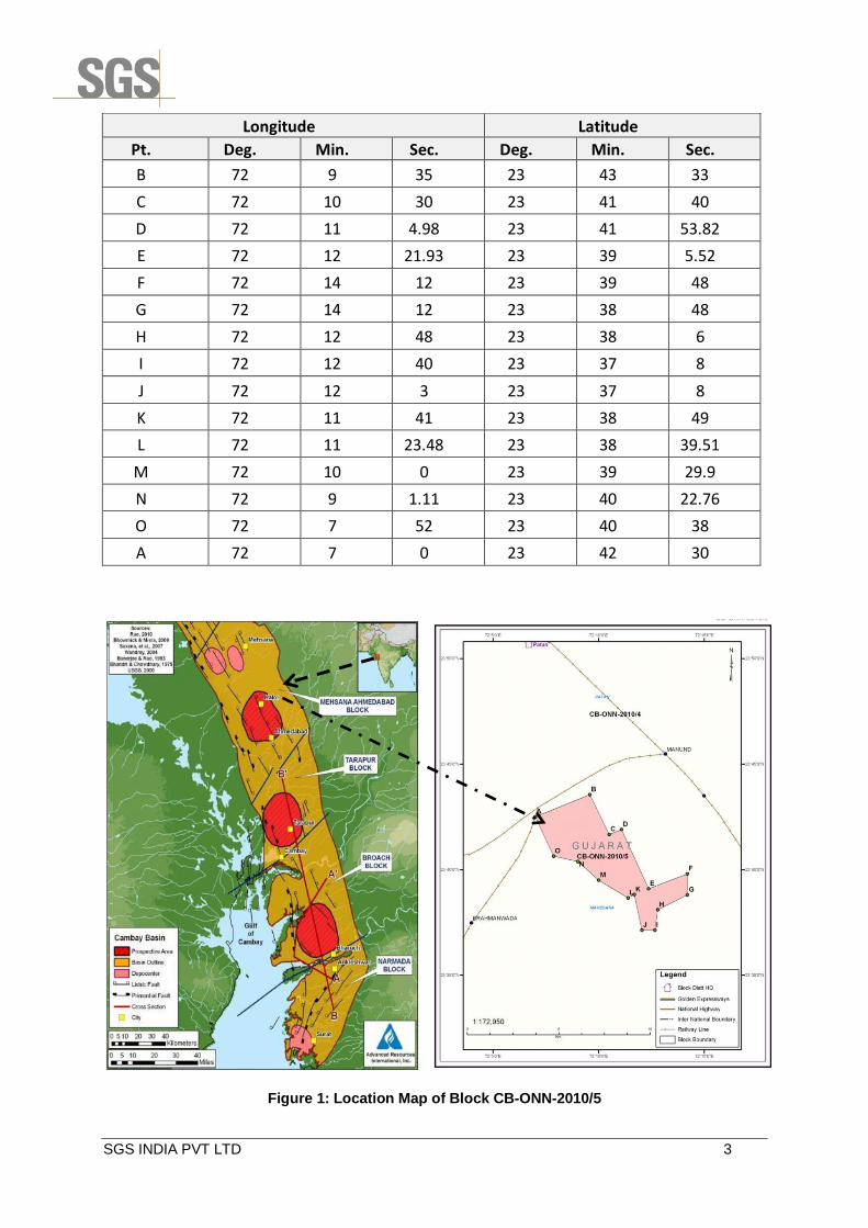
1.3 LOCATION OF BLOCK
The Block CB-ONN-2010/5 lies in the Ahmedabad-Mehsana Tectonic block of the Cambay
Basin. The block falls in the northern part of the Ahmedabad-Mehsana tectonic block, having
a number oil and gas fields, of which the prominent ones are Kalol, Jotana, Sobhasan,
Becharaji and Balol. Lanwa and south Patan fields are located to the southeast and
northwest respectively of the block.
The block is extensively covered by 2D Seismic lines and also by 3D seismic data. The 2D
seismic data is of various vintage and the 3D data was acquired in 2007. Five exploratory
wells viz, Chaveli-1, Mehsana-17, Mehsana-Horst-1, DNDR-1 and Lanwa-1 have been
drilled in the block. However, the wells drilled within the block were abandoned as no
hydrocarbon was interpreted in the well logs. But Mehsana-19 well, near the southeast
boundary of the block is oil bearing in Tarapur Formation of Oligocene age.
It covers an area of 49 sq. km and is bounded by the points having following coordinates:
Longitude Latitude
Pt. Deg. Min. Sec. Deg. Min. Sec.
A 72 7 0 23 42 30
SGS INDIA PVT LTD 3
Longitude Latitude
Pt. Deg. Min. Sec. Deg. Min. Sec.
B 72 9 35 23 43 33
C 72 10 30 23 41 40
D 72 11 4.98 23 41 53.82
E 72 12 21.93 23 39 5.52
F 72 14 12 23 39 48
G 72 14 12 23 38 48
H 72 12 48 23 38 6
I 72 12 40 23 37 8
J 72 12 3 23 37 8
K 72 11 41 23 38 49
L 72 11 23.48 23 38 39.51
M 72 10 0 23 39 29.9
N 72 9 1.11 23 40 22.76
O 72 7 52 23 40 38
A 72 7 0 23 42 30
Figure 1: Location Map of Block CB-ONN-2010/5

SGS INDIA PVT LTD 4
1.4 IDENTIFICATION OF PROJECT AND PROJECT PROPONENT
The proposed project is for Exploratory drilling of four (04) wells and 3D Seismic survey for
exploration of hydrocarbons at Chanasma and Becharji Taluka of Patan and Mehsana
District in Gujarat. The project is developed by PICPL and FIL.
Pan India Consultants Pvt. Ltd. – It was established in 1981 and they provide high-value,
high technology products and comprehensive support services in verticals such as
Geophysics, Hydrography, Oceanography, Hydraulics, Railway Rolling stock etc. The
Company also provides services and solutions across Consulting, Marketing, Commissioning
and Maintenance of Engineering and Electronic Systems Equipment, Instruments, Software
Developments, Geomatics and Geotechnical Services.
Frost International Ltd. - Incorporated in 1995, is recognised as a star trading house by the
Ministry of Commerce and Industry, India, for having consistently exported according to the
policies and guidelines of the Government of India and Federation of Indian Export
Organizations. For over 18 years, Frost International trades in diverse commodities like
minerals and metals, plastics, textiles, fabrics, agro commodities, equipment, and others.
The Company has also forayed into businesses such as Public Private Participation (PPP) in
the Transportation space, initiation of stevedoring operations at the Bhavnagar Port in
Gujarat and setting up of a wind farm in Tamil Nadu.

SGS INDIA PVT LTD 5
CHAPTER 2: PROJECT DESCRIPTION
2.1 BRIEF DESCRIPTION AND NATURE OF PROJECT
PICPL plans to undertake exploratory drilling and Seismic survey for an onshore block CB-
ONN-2010/5 of about 49 sq. Km at Patan and Mehsana district of Gujarat.
Type of Project
As per EIA Notification dated 14th September 2006 (and subsequent amendments) of
Ministry of Environment and Forests (MOEF) Sr. no. 1(b), all projects of offshore and
onshore oil and gas exploration, development and production requires prior
Environmental Clearance (EC). The proposed project belongs to Category ‘A’ and
requires Environmental Clearance from MOEF.
Need of Project
Energy, be it conventional or non-conventional is the basic requirement for the mankind. In
present day scenario, the consumption of energy has been increased with the growth of
population and their demand for improved amenities. Keeping the required growth rate and
rising energy demand for hydrocarbons in view, the Government of India has come out with
plans to encourage national, private and foreign companies to explore and develop the
hydrocarbon prospects. With this objective, the consortium of PICPL and FIL has been
awarded a block in Cambay Basin of India under the Production Sharing Contract (PSC) with
the Government of India. The current oil and gas reserve in the block by Directorate General
of Hydrocarbons (DGH), Government of India is estimated to be about 6.97 MMBBL.
Objectives of the Project
On the basis of the analysis of seismic survey data of the block CB-ONN-2010/5, PCIPL will
plan to drill the exploration wells to determine the presence of hydrocarbons in the identified
geological formations. The exact areas for drilling have not been defined, but they will be
strictly confined to the block boundary. The objectives of the exploration wells are:
To drill and evaluate the hydrocarbon prospects in the area;
To determine the commercial viability of the hydrocarbon potential of the designated
prospects;
Before commencement of the actual drilling operations, the access roads to the drill site
would be upgraded and strengthened, if needed. This will be followed by construction of a
flat rectangular drilling site of approximately 100 m X 120 m for well site and around
100mX50m for camp area to facilitate drilling and testing of the well.
SGS INDIA PVT LTD 6
Details of Alternate Site
No alternate site is examined as the block is awarded by Ministry of Petroleum and Natural
Gas, Government of India in the Ninth round of its New Exploration Licensing Policy (NELP).
2.2 SITE ANALYSIS
The site is well connected from both Mehsana and Patan district. Mehsana ~ 17 km (NE) and
Patan 12 km (N) from Block boundary. The nearest railway station is Chanasma at less than
one kilometre from the north-west corner of the block while Mehsana is at a distance of 17
kms. The nearest airport is Sardar Valabhbhai Patel in Ahmedabad which is about 75 kms
from the NE corner of the boundary.
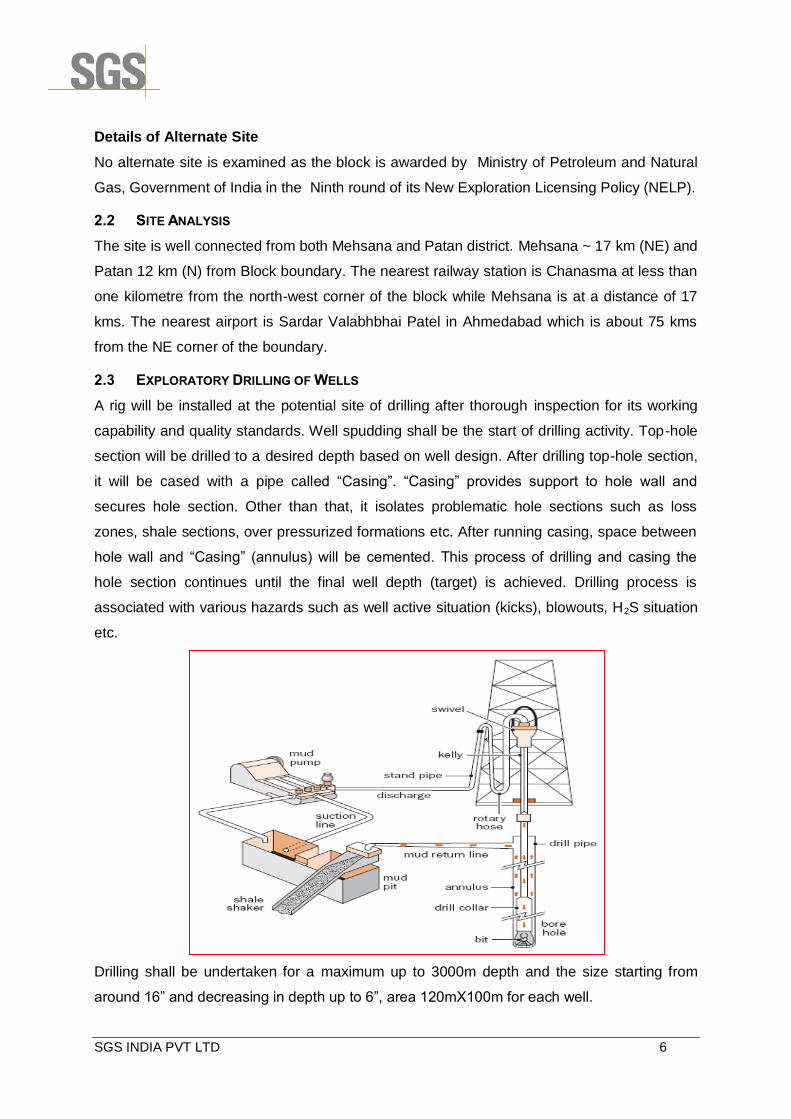
2.3 EXPLORATORY DRILLING OF WELLS
A rig will be installed at the potential site of drilling after thorough inspection for its working
capability and quality standards. Well spudding shall be the start of drilling activity. Top-hole
section will be drilled to a desired depth based on well design. After drilling top-hole section,
it will be cased with a pipe called “Casing”. “Casing” provides support to hole wall and
secures hole section. Other than that, it isolates problematic hole sections such as loss
zones, shale sections, over pressurized formations etc. After running casing, space between
hole wall and “Casing” (annulus) will be cemented. This process of drilling and casing the
hole section continues until the final well depth (target) is achieved. Drilling process is
associated with various hazards such as well active situation (kicks), blowouts, H2S situation
etc.
Drilling shall be undertaken for a maximum up to 3000m depth and the size starting from
around 16” and decreasing in depth up to 6”, area 120mX100m for each well.
SGS INDIA PVT LTD 7
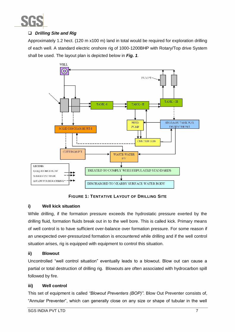
Drilling Site and Rig
Approximately 1.2 hect. (120 m x100 m) land in total would be required for exploration drilling
of each well. A standard electric onshore rig of 1000-1200BHP with Rotary/Top drive System
shall be used. The layout plan is depicted below in Fig. 1.
FIGURE 1: TENTATIVE LAYOUT OF DRILLING SITE
i) Well kick situation
While drilling, if the formation pressure exceeds the hydrostatic pressure exerted by the
drilling fluid, formation fluids break out in to the well bore. This is called kick. Primary means
of well control is to have sufficient over-balance over formation pressure. For some reason if
an unexpected over-pressurized formation is encountered while drilling and if the well control
situation arises, rig is equipped with equipment to control this situation.
ii) Blowout
Uncontrolled “well control situation” eventually leads to a blowout. Blow out can cause a
partial or total destruction of drilling rig. Blowouts are often associated with hydrocarbon spill
followed by fire.
iii) Well control
This set of equipment is called “Blowout Preventers (BOP)”. Blow Out Preventer consists of,
“Annular Preventer”, which can generally close on any size or shape of tubular in the well
SGS INDIA PVT LTD 8
bore and closes the annular space between drill string and casing. Another type of blowout
preventer is a “Ram Preventer”. Ram preventers are of two types i.e., Pipe Rams and Shear
Rams. Pipe rams also close the annulus between drill string and casing, but they have a
fixed size. As such a specific pipe rams can be closed on a specific size of pipe.
Shear rams are generally the last choice of preventer to be operated as they shear drill string
and shut off the well bore. After determining the existing formation pressure and other
geological complexities from the seismic data, appropriate BOP will be used as per standard
oil field guideline for the same.
Drilling Fluids (Mud)
The role of the drilling fluid (mud) in pressure control is especially important. If the drill bit
penetrates a formation containing oil, gas or water under pressure, these fluids are
prevented from flowing into the borehole by ensuring that the drilling mud is of sufficient
density to the natural formation pressures. The density of the mud can be increased by the
addition of barite weighting material. Bentonite is employed to improve the theological
properties and enable the drill cuttings to be transported from the hole while drilling and also
be suspended in the fluid while the drill bit is being changed. The barite used in the drilling
mud would be as per API standard specifications.
Based on geological prognosis and predicted formation pressures, Water Based Mud (WBM)
will be used for all the wells considering environmental constraints and hazards.
The main components of drilling mud are slurry of inert solids suspended in a liquid phase.
The main constituents of the WBM are bentonite and barites, both of which are natural
minerals. In case if the WBM is not able to be used due to geological formation complexities
then low toxic oil base mud with less than 1% aromatic contents can be used after intimating
the MOEF and/or State Pollution Board.
The drilling fluids circulation system consists of several items of equipment. The mud pump
takes in mud from the mud pits and sends it out a discharge line to a standpipe. The
standpipe is a steel pipe mounted vertically on one leg of the derrick. The mud is pumped up
the standpipe into a flexible reinforced rubber hose called the Kelly hose. The Kelly hose is
connected to the swivel; goes down the Kelly, drill pipe and drill collars and exits at the bit.
The mud then does a sharp U-turn and heads back up the hole in the annulus. The annulus
is the space between the outside of the drill string and the wall of the hole. Finally, the mud
leaves the hole through a steel pipe called the mud return pipe and falls over a vibrating
screen like device called the shale shaker. The shaker screens out the cuttings from the
mud. The mud drains back into the mud tanks and is recycled back into the well via the mud
pump, while the drill cuttings which are inert materials of shale, sand, and clay fall into the
SGS INDIA PVT LTD 9
lined waste pits. The drilling fluids left over at the end of the particular well will be discharged
into the lined waste pits and dried. The pits will be provided with plastic liners to maintain
integrity and prevent any leakage. The drill cuttings cut by the bit are removed from the mud
by the shale shakers and other solids removal equipment and transferred to the waste pits.
Once the mud is cleaned it is pumped down the drill string again.
The drilling mud, which is pumped through the drill string, through the drill bit and then
returns up the annulus between the drill string and bore hole, serves a number of important
functions, including:
Removal of drilled solids (i.e. cuttings) from the bottom of the hole and their transport to
the surface for separation from the mud;
Lubrication and cooling of the drill bit and string;
Deposition of an impermeable cake on the well bore wall to seal the formation being
drilled; and
Countering the natural formation pressures and preventing uncontrolled flow of fluid from
the formations.
At the end of drilling of each well, whatever the fluid left in the pits will be treated &
transported to the next drilling location or disposed off in secured landfill site (pit).
Drill Cutting
The drill cuttings, cut by the bit, shall be removed from the mud by the shale shakers and
centrifuges and transferred to the mud tank. Once the mud shall be cleaned, it is pumped
down the drill string again. The drilling fluid will be re-used after extraction of drill cuttings and
necessary treatment. It is estimated that around 700-800MT of drill cuttings will be generated
as waste, which will be stored in a impervious pit with liner at the site and the pit will be
covered or treated as per waste disposal guidelines for such wastes. At the end of drilling of
each well, dried cuttings will be disposed off in secured landfill site (pit).
xiii) Drill-stem testing
If the geologist detects the presence of oil or gas in the drill cuttings, a drill-stem test is
frequently performed to evaluate the formation or zone from which the oil show was
observed. Drill-stem tests may also be performed when the driller observes a decrease in the
time required to drill a foot of rock, known as a "drilling break." Since porous rock may be
drilled easier than nonporous or less porous rock, a drilling break indicates the presence of
porosity, one of the qualities of reservoir rock. A drill-stem test enables the exploration
company to obtain a sample of the fluids and gases contained in the formation or interval
being tested as well as pressure information, which is determined by special gauges within
the test tool.
SGS INDIA PVT LTD 10
Drill-stem testing is accomplished by removing the drill string from the bore hole. The drill bit
is removed and a drill-stem test tool with a packer is attached. The test tool, packer, and drill
string are inserted back into the bore hole to the desired depth. The packer, which is an
expandable device, is set and expanded at the predetermined depth to isolate the zone to be
tested. The test tool contains a valve which may be opened and closed to allow formation
fluids to enter the test tool and drill string. If there is sufficient fluid and pressure within the
zone being tested, the formation fluid (oil, gas, water) may rise to the surface and flow into
special test tanks used for that purpose. If gas is present, it is burned at the surface as a
flare. By analyzing the rate of flow or the amount of formation fluid recovered in the drill string
and the formation pressures recorded, obtaining a good indication of reservoir characteristics
such as porosity, permeability, and the nature of the fluids or gas contained therein is
possible.
xiv) Surface Testing &Flaring
In case hydrocarbons are detected in the well, the quantity and quality will be tested. The
fluids & gases coming out from the well will be flared. The flaring will be intermittent and last
only for few days and it will not pollute environment. However, for flaring all the flaring
guidelines for onshore wells will be followed and the design, size and location of flaring stack
will be decided based on surrounding habitations and the flaring guidelines.
xv) Well logging
Drilling operations continue until the predetermined total depth of the well is reached. The
drill string is removed from the well bore to allow the insertion of logging tools, which are
lowered all the way to the bottom of the hole by means of a special cable. This cable
contains numerous electrical circuits. Signals detected by the tools are recorded in a
recording truck at the surface by means of the electrical circuits contained in the cable.
Electrical logs measure the natural electric potential and the effect of induced electricity on
the formations. Radioactivity logs measure the natural radioactivity and the effect of induced
radioactivity on the formations. Sonic logs measure the velocity of sound waves in the
formations. By analyzing these logs, experienced geologists and engineers can determine
the depth from the surface to various formations and intervals, formation characteristics such
as rock type and porosity, and indications of the presence of oil or gas and quantity.
xvi) Completing the well
When drill-stem testing and well-logging operations have been completed and the results
have been analyzed, the company management must decide whether to complete the well
as a producing well or to plug it as a dry hole. If the evidence indicates that no oil or gas are
present, or they are not present in sufficient quantity to allow for the recovery of drilling,
SGS INDIA PVT LTD 11
completion, and production costs and provide a profit on investment, the well will probably be
plugged and abandoned as a dry hole. If, on the other hand, evidence indicates the presence
of oil or gas in sufficient quantity to allow the recovery of these costs and provide a profit to
the company, an attempt will be made to complete the well as a producer.
If the well is to be plugged and abandoned as a dry hole, the well bore is filled with drilling
fluid, which contains additives which give it special properties that prevent its movement from
the well bore into the surrounding rock. Cement plugs are required within the well bore at
intervals where porosity has been detected to isolate these porosity zones and prevent the
movement of formation fluids from one formation to another. The cement is pumped into the
well bore through the drill string. The cement is mixed at the surface in special trucks which
are equipped with high-volume pumps. The pumps are connected to the drill string which has
been inserted into the well bore to a predetermined depth. A quantity of cement is pumped
into the well bore through the drill string and displaced out of the bottom of the drill string with
drilling fluid. The drill string is then pulled up to the next interval that is to be cemented. This
process is repeated until all the required plugs have been set. A cement plug is also set at
the base of the surface casing, which remains in the hole, and another plug is set at the
surface. In cultivated areas the surface casing is cut off below plow depth. A steel plate is
welded at the top of the surface casing. All drilling equipment and materials are removed
from the drill site. The pits are allowed to dry up and are backfilled and the site is restored as
nearly as possible to its original condition.
If a decision is made to attempt to complete the well as a producer, casing is delivered to the
site. The well bore is filled with drilling fluid that contains additives to prevent corrosion of the
casing and to prevent the movement of the fluid from the well bore into the surrounding rock.
The casing is threaded together and inserted into the well bore much in the same manner as
the drill string. Casing may be inserted to a total depth of the hole or a cement plug may have
been set at a specific depth and the casing set on top of it. Cement is mixed at the surface
just as if the well were to be plugged. The cement is then pumped down the casing and
displaced out of the bottom with drilling fluid or water. The cement then flows up and around
the casing, filling the space between the casing and the well bore to a predetermined height.
xvii) Restoration of Cutting Containment Area
At the conclusion of well testing at each drilling site, solar drying will dewater the waste pits.
All residual solids and liner will be covered with thick column of native soil. The cutting mud is
inert and with HDPE (High Density Poly-ethylene) linings of the pit in place it will not pose
any scope of environmental hazard. Grading will take place to ensure natural run-off. Any
remaining topsoil that has been stocked during the site clearance will be re-spread over
SGS INDIA PVT LTD 12
appropriate portions of the site. Plantation of saplings will be commenced during the next
rainy seasons to restore the site and conduct afforestation in and around the site.
xviii) Drilling Schedule
Total estimated time required for drilling of one well will be about 90-120 Days and testing
period of 15-20 days.
xix) Restoration of Drilling Site
In the event that appraisal drilling is unsuccessful at any particular site then the site will be
cordoned off to avoid any accidents. The sludge will take long time to dry and accidents like
someone falling into the sludge may take place. PICPL shall actively manage the
reinstatement process till the time the site is reinstated to its original condition. The
restoration process includes the following activities:
Demobilization of equipment and machinery from the site;
Dismantling of all civil structures except disposal pits;
Covering of drill cutting and mud disposal pits after adequate drying and secure land
filling;
Decontamination of soil, if any; etc.
xx) Power Requirement
The power requirement for the drill rig will be met by four (04) x 500 KVA DG sets to operate
the drill rig. At a time, maximum three DG sets shall be in operation except during test flaring
and one DG set shall be kept as stand by. During test flaring, only one DG set shall be in
operation to meet the power requirement.
The power requirement for the campsite will be catered through one Diesel Generators (DG)
sets of 100 KVA.
xxi) Water Requirement
The water requirements for the drilling and domestic purposes at drill site will be to the order
of 20 kilolitres per day (KLD). The camp will normally operate with around 40 personnel and
will consume water @ 5 KLD for domestic purpose only.
Water requirement will be met from nearby local sources.
xxii) Fuel Requirements & Storage
Estimated consumption of HSD shall be about 4-5 KL for entire operation and majority of it
will be used drilling rig and will be stored temporarily in 200 lit drums at the drilling site.
xxiii) Air Emissions & Noise
Sources of air emissions and noise will be limited to generators, well test flaring, vehicles etc
during the proposed project activities. By careful design of well test flaring and regular

SGS INDIA PVT LTD 13
maintenance of all vehicles and other machines shall keep air emissions and noise to a
minimum. Average cumulative noise from DG sets and drilling equipment will be in the range
of ~ 70 to 80 dB.
xxiv) Waste Disposal
Conduits will be laid to collect wastewater from kitchens, toilets, bathing and washing areas.
Wastewater from toilets shall be sent to soak pit after passing through Septic tank while
same from other sources shall be sent to soak pit for final disposal. On completion of the
exploration activities, all the installations will be removed without leaving debris. Kitchen
waste will be dumped in humus pit for its future use as manure. Other solid wastes such as
plastics, metals, and workshop waste will be removed by a contracting agent. All used oil and
anything mechanically reusable will be provided free to local gasoline stations for use as
seconds. Hazardous materials, such as batteries and aerosols will be placed in a separate
container, appropriately marked, and disposed of as per relevant guidelines. Medical waste
will be bagged and binned in a separate container appropriately labelled. This waste will be
disposed of either at a local hospital or as per guidelines for disposal of medical waste.
The waste and spent mud generated from drilling of wells would be collected in a lined pit
and impervious sheeting will be underlined for all the chemical storage areas. The waste
water to be generated during drilling activities will be collected in a pit lined with HDPE to
prevent seepage. The mud components during the storage form a bentonite (clay) lining
along the pit wall preventing the seepage of water to the underground strata. Any
hydrocarbon contamination will be skimmed off from site before proceeding to the next site.
This would ensure that no leaching or subsurface contamination finally reaches the
groundwater table.
Drill cuttings which are inert materials of shale, sand, and clay fall into the lined waste pits.
The drilling fluids left over at the end of the particular well will be discharged into the lined
waste pits and dried. The drill cuttings cut by the bit are removed from the mud by the shale
shakers and other solids removal equipment and transferred to the waste pits.
xxv) Staffing and Project Employment
The overall management and coordination of the exploration drilling of wells program will be
the responsibility of the country office. Local staff will comprise individuals hired for different
project activities. The country office will be responsible for:
Providing all necessary backup information to the Contractor;
Logistical details;
Providing spare parts, food and all necessary equipment;
Data shipments;
SGS INDIA PVT LTD 14
Liaison with the contractor’s office;
Taking care of other administrative matters such as explosive licenses, flight
authorizations, import licenses, etc.
Around 40 personnel including technical and other labors will be involved during drilling
phase.
Base camp
The staff will be housed in one base camp established at a convenient location for the
program. Typically, such camps have trailer and tented accommodation for staff, storage
space for equipment, parking spaces for the vehicles and cooking facilities. Small secondary
or field camps may be set up for limited periods of time as the need arises. Arrangement
shall be made for 90-100 personnel
Permitting
With the permission of administrative authority and owner, the land for the drilling work will
be acquired on lease basis from the respective landowners and will adequate compensation
be paid for the same.
2.4 SEISMIC SURVEY
The purpose of the survey is to map subsurface geological structures, which may serve as
reservoirs for oil and gas. The survey will produce a subsurface map within the block area
and identify geological features such as anticlines, synclines, faults and folds. Subsurface
geological maps produced from the seismic survey will reveal structures most likely to
contain these resources and enable potential drilling locations to be determined with greater
accuracy.
Method of Seismic Survey
Seismic survey does not involve acquiring and occupying any part of the land defined by
dimensions for any continuing activity. Seismic survey is carried out on specific straight lines
along which the seismic crew moves fast performing the required activity covering 4 to 6 km
a day. The crew does not return to the place once covered. In the proposed programme, the
Seismic survey will be done as per the proposed parameters given below. The seismic
survey project involves topographic surveying, shot hole drilling, laying the cables and
geophones on pre-decided geometry, generating seismic energy and recording the seismic
energy. The activities performed shall be as follows:
i) 3D Seismic Survey Parameters
Energy source : Explosive
Charge Size : 3.5 kg
SGS INDIA PVT LTD 15
Shooting geometry : Orthogonal, Symmetric Split Spread
Shot line interval (SLI) : 480 m
Shot point interval : 40m
Shot hole pattern : Single hole per shot
Direction of shooting : E_W
No. of Receiver Line : 12
No. of channels per line : 240
Total active channels : 2880
Receiver line interval (RLI) : 240 m
Group interval : 40 m
Far trace offset : 2560 m (in- line)
Maximum Offset : 5189 m
Near Offset : 28 m (in-line)
Bin size : 20m x 20m
Foldage : 12 x 5= 60
Swath roll : N -S
iii) Topographic survey work
In this, the surveyor fixes a straight line on the ground (using survey instruments like
compass, theodolite etc.) which is identified on the ground by numbered wooden pegs about
one foot long driven into the ground by a few inches with a fixed spacing of 40m between the
pegs. Using survey instruments the elevation above mean sea level at these survey points is
determined.
For preparing this straight line, both access and the line of sight when viewed through the
survey instruments has to be clear. Therefore, the obstructions to the line of sight like bushes
and branches hanging low if any will have to be cut. Clearance of all lines and rights of way
(1-3 m) shall be carried out. The survey crew consisting of surveyors and workers who carry
the survey instruments, bamboo pieces, tools etc. should be able to walk along the line. This
involves clearing the under growth like small bushes, creepers etc. if any to prepare a
footpath. There is no need to cut/remove any mature tree.
The orientation of the line is measured by determining the latitude and longitude at certain
points of this line using survey instruments so that the position of the line of survey may be
plotted on the topo-sheets. Subsequent activities viz. Shot hole drilling and seismic data
recording are done on the line prepared by the surveyor.
SGS INDIA PVT LTD 16
The survey crew consisting of surveyors and workers who carry the survey instruments,
bamboo pieces, tools etc. should be able to walk along the line without causing any damages
to the plants. They will clear bushes for moving on the lines.
Maps will be generated for the survey area showing details such as:
Topographic features;
General terrain and vegetation type;
Cultivation or crops of any nature;
Proximity of buildings and villages (with distances);
Proximity of all water sources, springs, water wells, etc. (with distance )
Locations, width and depth of all rivers and streams;
Locations of electric power or telephone lines, pipelines, gas lines etc.
Positions and condition of any roads or footpaths or other access; and
Stations at which a full length source or receiver array will exceed a 5 m elevation change
within the array.
In addition a detailed map shall be produced for each line showing access routes between
individual source points, sequence in which they should be recorded, any known restrictions,
and distances to hazards.
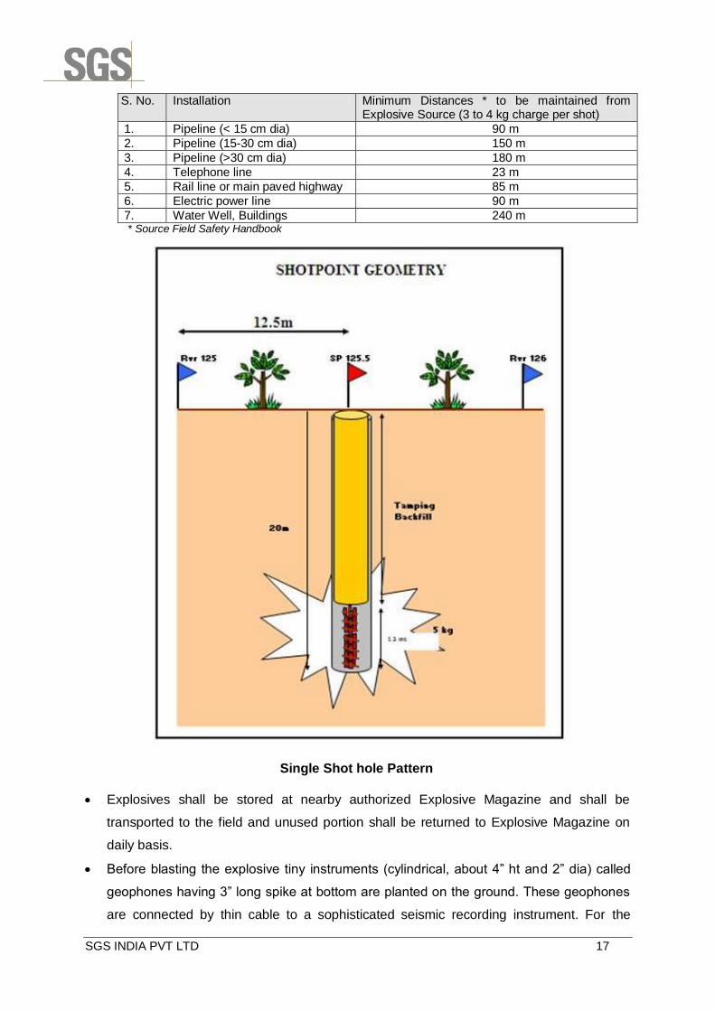
iv) Shot hole Drilling
Shot holes will be drilled on pre decided grid. The depth of each shot hole may vary between
20 to 40m and drilled with 4 inch diameter drill bit using water based mud. The shot hole
drilling operation will be carried out either manually or mechanically. In each shot hole a
small quantity of explosive around 3 - 4 kg will be loaded and blasted to generate seismic
energy. All necessary precautions will be taken as per standard industry practice while
loading and blasting the explosive.
v) Recording of seismic data
Seismic energy which is only a sound wave is generated by blasting small quantity of seismic
explosive lowered to the bottom of the shot hole filled with muddy water. Blasting is done
using an electric detonator. This job is handled by licensed technicians. In normal
circumstances, no material is ejected into the air and the noise from the underground blast is
heard as a dull thud.
Blasting is done using an electric detonator
Suggested minimum distances from various locations shall be as per given hereunder:
SGS INDIA PVT LTD 17
S. No. Installation Minimum Distances * to be maintained from Explosive Source (3 to 4 kg charge per shot)
1. Pipeline (< 15 cm dia) 90 m
2. Pipeline (15-30 cm dia) 150 m
3. Pipeline (>30 cm dia) 180 m
4. Telephone line 23 m
5. Rail line or main paved highway 85 m
6. Electric power line 90 m
7. Water Well, Buildings 240 m * Source Field Safety Handbook
Single Shot hole Pattern
Explosives shall be stored at nearby authorized Explosive Magazine and shall be
transported to the field and unused portion shall be returned to Explosive Magazine on
daily basis.
Before blasting the explosive tiny instruments (cylindrical, about 4” ht and 2” dia) called
geophones having 3” long spike at bottom are planted on the ground. These geophones
are connected by thin cable to a sophisticated seismic recording instrument. For the

SGS INDIA PVT LTD 18
proposed survey, there will be some live channels (geophone) stationed at regular
interval of 40 m i.e. they are spared out as per the survey parameters given above. This
is called a spread. One shot hole is blasted either at the end or in the middle of the
spread.
The wave generated by the blast travels down into the ground gets reflected at various
sedimentary layers in the subsurface, travels upward and when it reaches the ground
surface along the line, is picked up by the geophones. The data from geophones is
transmitted to seismic recording instruments through thin cables and small electronic
data collecting boxes. The whole system of one shot hole and the spread of 300 plus
recording geophones which result in one record is moved systematically along the line
performing the blasting and recording operations till the end of the line. Thus, lines after
line are covered.
In areas like agricultural fields portable equipments including geophones, cables,
electronic data collecting boxes etc are deployed which are carried as head loads. To the
extent roads and tracks are available the crew uses light automobiles to transport
equipment and personnel to reach the work spot and return after the day’s work.
The data acquired in the fields is processed in seismic data processing centers and
interpreted at headquarters. With the data acquired in the grid of survey lines structural

SGS INDIA PVT LTD 19
maps of the subsurface sedimentary layers of interest will be prepared which will reveal
places suitable for hydrocarbon accumulation.
vi) Demobilization and Site Restoration
Once the survey and recording are finished, equipment will be removed and personnel
will leave the site. The site will also be restored to its original state by filling and burying
all holes as well as collecting all wastes and materials out of the site. It is expected to
take approximately one month to complete the site restoration including recording public
complaints, if any.
vii) Access to the Survey Zone
Where no existing roads or tracks exist, the seismic will be man-portable. In this case only
foot-paths wide enough for one person carrying equipment to pass will be cleared for
access and no mature trees will be cut, as already described above. Road and track use
is monitored continuously throughout the project by the permitting and quality control staff.
Project personnel may only use existing vehicle tracks.
Water Requirements
The water requirement for the survey team and the domestic needs of the temporary
residential camp will be to the order of around 7-8 kilolitres per day (KLD). The camp will
normally operate with 40 personnel. Unskilled worker force (maximum 200) as per
requirement shall be hired locally.
Potable water shall be provided for drinking purposes while water for other usages shall be
provided from local sources. In case of inadequate water supply, suitable water transportation
arrangement will be made to cater to the water requirement of campsite through pipeline/a
road tanker.
Power Requirement
The power requirement for the campsite will be catered through Diesel Generator (DG) sets to
be temporarily stationed at the campsite. The rated capacity of each of the 2-DG sets for the
campsite will be in the order of 50 KVA. At any point of time only one DG set of 50 KVA will be
operational and one will be kept as standby.
Waste Disposal
Conduits will be laid to collect wastewater from kitchens, toilets, bathing and washing areas.
Wastewater from toilets shall be sent to soak pit after passing through Septic tank while
same from other sources shall be sent to soak pit for final disposal.
On completion of the survey, all the installations will be removed without leaving debris. Food
waste will be buried in a pit (1.5 m in depth) and covered with soil to avoid contamination and

SGS INDIA PVT LTD 20
or disease. Paper waste will be collected and given to local vendor. Other solid wastes such
as plastics, metals, and workshop waste will be sold to a recycler. All used oil and anything
mechanically reusable will be provided free to local gasoline stations for use as seconds.
Hazardous materials, such as batteries and aerosols will be placed in a separate container,
appropriately marked, and disposed of as per relevant guidelines. Medical waste will be
bagged and binned in a separate container appropriately labeled. This waste will be
disposed of either at the disposal site of the local hospital or as per guidelines for disposal of
medical waste.
Emissions and Noise
Sources of air emissions will be limited to generators and vehicles. The main camp will
include an area reserved and properly equipped for the maintenance of vehicles and other
machines. Regular maintenance of all project vehicles and other machines should keep air
emissions and noise to a minimum. In critical habitats, if road access exists, noise from
vehicles will be minimized by speed restrictions.
Timing of Seismic Survey Activity
Surveying, shot hole drilling and recording operations are expected to commence after
analysis of findings of proposed exploratory drilling of two (2) wells and would be completed
within a period of 2-3 months.
Staffing and Project Employment
The overall management and coordination of the seismic survey program will be the
responsibility of the seismic contractor. Local staff will comprise individuals hired for
conducting seismic activities.
Base Camp
The staff will be housed in one base camp established at a convenient location for the
seismic program. Typically, such camps have trailer and tented accommodation for staff,
storage space for equipment, parking spaces for the vehicles and cooking facilities. Small
secondary or field camps may be set up for limited periods of time as the need arises.
The campsites will provide temporary accommodation to all the survey crew and the
contractor personnel. At one point of time, it is anticipated that there will be about 40 skilled
personnel (excluding the labour) at a campsite during the survey campaign. The site will be
self- contained with the available power supply, medical, housing, sewage and will clearly
display respective utilities.
Campsites for the personnel at work will be strategically positioned. Each campsite will
comprise of an area of approximately 2.25 hect. (150 mx150m). The campsite will consist of
SGS INDIA PVT LTD 21
offices, equipment storage area and accommodation.
Equipments and Other Accessories for the Project
The basic equipments and other accessories required for a seismic survey program (not
intended to be a comprehensive list) include:
GPS, Total Stations and other survey instruments;
Drilling Equipments including air compressors to operate drilling pumps and
hammers, for drilling shot holes;
Recording equipments in a recording truck with generator and air conditioning units,
digital telemetry recording instrument, tape recorder cartridge recorder or equivalent
for storage of recorded data, plotter for generating paper record of acquired seismic
data, digital grade geophones, geophone testers, seismic cables, etc.;
Blaster to set-off charges in the holes, etc.;
Satellite phones and VHF radio transceivers for communication;
Four-wheel drive vehicles for Transportation and supply;
Light vehicles with VHF Radios for Transport of project personnel; and
Dedicated ambulances.
Permitting
PICPL will undertake prior permission from landowners/land users whose property may be
traversed by any of the proposed area for seismic survey. PICPL will contact and visit the
stakeholders to explain the program and discuss access and identify any issue requiring
special attention along the proposed seismic survey area.
2.5 PROPOSED INFRASTRUCTURE
The proposed exploratory drilling of well will involve temporary construction of foundation for
stability of rig and pits for storage of water, waste water and drill cutting. While seismic
survey shall not require any construction work.

SGS INDIA PVT LTD 22
CHAPTER 3: REHABILITATION AND RESETTLEMENT (R&R)
PLAN
3.1 REHABILITATION AND RESETTLEMENT (R&R) PLAN
No permanent acquisition of land for the project. The area required for drilling operation will
be temporarily taken on lease for few months and if there is discovery of Oil or Gas then it will
be converted in to long time lease of 20years. Land requirement details are as per given
hereunder:
For exploratory drilling of a well, an area of 1.2 hect. (120 m x100 m) for drilling activities and
0.5 hect. for camp site shall be required. In case of confirmation of commercially viable
hydrocarbons, the same area is procured otherwise shall be handed over to land owner. For
conducting, Seismic survey, land in terms of right of way (ROW) of 1-3 m shall be required.
Additionally, an area of 2.25 hect. (150 mx150m) shall be required on lease for camp site.
The seismic data acquisition survey will be carried out during day time, while exploratory
drilling will be carried out round the clock. While carrying out the survey, if any damage is
done to standing crops, compensation will be paid to the owners as per the guide lines of
local revenue authority.

SGS INDIA PVT LTD 23
CHAPTER 4: PROJECT SCHEDULE AND COST ESTIMATES
4.1 PROJECT SCHEDULE AND COST ESTIMATES
The proposed exploratory drilling period is expected to be about 90-120 Days and testing
period of 15-20 days.
The estimated cost of the project is 8.75 million USD.
SGS INDIA PVT LTD 24
CHAPTER 5: ANALYSIS OF PROPOSAL
5.1 ANALYSIS OF PROPOSAL (FINAL RECOMMENDATIONS)
The tangible benefits are: production of indigenous oil and gas to reduce dependency on
imported oil and gas.