scppa rfp test well drilling drilling permits; geothermex will coordinate the process of drilling,...
TRANSCRIPT

SOUTHERN CALIFORNIA
PUBLIC POWER AUTHORITY
Request for Proposals
for
Drilling of Exploratory Temperature-gradient Wells for the SCPPA Area One Geothermal Energy Project
RFP Date: June 30, 2008
Response Deadline: August 11, 2008, by 2:00 p.m. PST

SCPPA Request for Proposals for
Drilling of Exploratory Temperature-gradient Wells for the SCPPA Area One Geothermal Energy Project
TABLE OF CONTENTS
SECTION TITLE PAGE
1.0 Introduction .......................................................................................................... 1
1.1 Purpose, Project Site, Well Locations and Pre-bid Conference ...................... 1 1.2 Background ..................................................................................................... 1
2.0 Scope of Work ...................................................................................................... 2
3.0 Request for Proposals (RFP) Schedule .............................................................. 3
4.0 Requirements for Proposal .................................................................................. 4
4.1 Transmittal Letter ............................................................................................ 4 4.2 Prices .............................................................................................................. 5 4.3 Firm Qualifications .......................................................................................... 5 4.4 Key Personnel ................................................................................................. 6 4.5 License ........................................................................................................... 6 4.6 Subcontractors ................................................................................................ 6 4.7 Technical Approach ....................................................................................... 6
5.0 Proposal Selection Criteria ................................................................................... 7
6.0 Submission Requirements ................................................................................... 8

SCPPA Request for Proposals for
Drilling of Exploratory Temperature-gradient Wells for the SCPPA Area One Geothermal Energy Project
APPENDICES
SECTION TITLE
A1 Approximate Proposed Locations of Drilling Wells A2 LADWP Site Vicinity Map A3 IID Site Vicinity Map B Drilling and Logging Program for Temperature-gradient Wells C LADWP License – Access Agreement (Draft) D LADWP Contract Insurance Requirements E IID Encroachment Permit Application F SCPPA Bidder’s Bond (Surety Bond)

1
SOUTHERN CALIFORNIA PUBLIC POWER AUTHORITY
Request for Proposals for Drilling of Exploratory Temperature-gradient Wells
for theSCPPA Area One Geothermal Energy Project
1.0 Introduction
The Southern California Public Power Authority (SCPPA) intends to contract with one or more firms to provide exploratory well drilling services to support the Area One Geothermal Energy Project.
1.1 Purpose, Project Site, Well Locations and Pre-bid Conference
SCPPA is considering a geothermal power plant project in Imperial County, California, near the Salton Sea. The exploratory phase of the project requires drilling of temperature-gradient wells.
The well drilling will be performed in the lands owned by two of its members, the Los Angeles Department of Water and Power (LADWP) and the Imperial Irrigation District (IID). The land maps for the proposed well drilling, approximately 10 square miles in total area, are attached as Appendices A2 and A3. The proposed locations of wells to be drilled must be within the boundaries of the lands shown.
Approximate locations of wells to be drilled are shown in Appendix A1. Boundaries near wells and well locations will be surveyed and staked in the field. Respondent may adjust the actual well locations up to 100’ from the locations indicated. The site is accessible to construction equipment. Short new roads may be required to gain access to the well site(s).
Approximately 3 weeks after the issuance of the RFP, all proposed respondents shall attend a mandatory conference at the exploratory well site. Proposed respondents will be notified of the exact time, date and the meeting location prior to the conference.Each respondent must attend this mandatory conference to be considered a responsive bidder.
1.2 Background
SCPPA, a joint powers authority and a public entity organized under the laws of the State of California, was created pursuant to the Government Code of California and a Joint Powers Agreement for the purpose of planning, financing, developing, acquiring, constructing, operating and maintaining projects for the generation or transmission of electric energy.
Membership consists of eleven cities and one irrigation district which supply electric energy to Southern California, including the municipal utilities of the cities of Anaheim,

2
Azusa, Banning, Burbank, Cerritos, Colton, Glendale, Los Angeles, Pasadena, Riverside, and Vernon, and the Imperial Irrigation District.
SCPPA is governed by its Board of Directors, which consists of representatives from each of its members. The management of SCPPA is under the direction of an Executive Director, who is appointed by the Board. SCPPA currently holds capacity entitlements in the following projects and 100% of the output is sold and controlled by its member utilities:
SCPPA Projects
� Palo Verde Power Project
� Hoover Uprating Power Project
� San Juan (Unit 3) Power Project
� Magnolia Power Project
� Southern Transmission System
� Mead-Adelanto Transmission Project
� Mead-Phoenix Transmission Project
� Pinedale Natural Gas Reserves Project
� Gould Geothermal Project
2.0 Scope of Work
Successful respondent(s) will be required to provide the following services and comply with all applicable regulatory requirements related to such services:
(1) Obtain necessary permits from State and local governing agencies for well drilling;
(2) Perform exploratory temperature-gradient well drilling for three 61/8-inch diameter wells up to 3,000 feet below ground surface as per specifications shown in Appendix B within the applicable time limits set by the California Division of Oil, Gas and Geothermal Resources;
(3) Work and coordinate with GeothermEx, a SCPPA consulting firm for the project, to ensure the use of proper drilling techniques and the maintenance of good quality drilling logs and core records;
(4) As directed by GeothermEx, drill one additional well (with cumulative total of four wells) if one or more of the three wells to be drilled fail(s) to indicate the significant temperatures desired by SCPPA and GeothermEx;

3
(5) Provide actual locations, survey coordinates, and technical data of wells drilled; and
(6) Either (i) file all necessary drilling records for any well that is considered completed as defined by Section 1950 of Subchapter 4 of Title 14 of the California Code of Regulations, or (ii) restore the site to existing condition or better after completion of drilling operation, including any plugging and abandonment, or (iii) both (i) and (ii) above.
GeothermEx and IID will assist the successful respondent(s) in obtaining any necessary drilling permits; GeothermEx will coordinate the process of drilling, and will provide logging services to the exploratory wells. A GeothermEx engineering representative will be on-site at the start of the drilling and at critical points throughout the drilling operations. As needed, an independent construction supervisor may also be on-site to supervise drilling operations and provide continuous oversight of construction. Data collected from drilling operations shall be transmitted to SCPPA through GeothermEx on a daily basis.
3.0 Request for Proposals (RFP) Schedule
SCPPA has established the following schedule for this RFP, but reserve the right to amend the proposed schedule at any time:
1. Issuance of RFP: June 30, 2008.
2. Mandatory Site Visit: To be scheduled approximately 3 weeks after issuance of RFP.
3. RFP Submittal Deadline: August 11, 2008.
4. RFP Evaluation Period: Approximately 4 weeks.
5. Issue RFP Results: On or about September 8, 2008.
6. Obtain Permits and Project Application: 4 to 8 weeks.
7. Start Well Drilling: by November 3, 2008, subject to change if environmental document is required.
8. Complete Well Drilling: by February 2, 2009, subject to change if environmental document is required.
9. Clean Up and Close Project: by February 9, 2009, subject to change based upon commencement and completion of drilling.
10. Expiration of RFP: June 30, 2009.
Upon approval and acceptance by SCPPA, respondents may submit an alternative drilling schedule and the associated changes in bid price with adjustment of up to 3

4
months from the schedule shown above. In no case shall the Close of Project be after May 9, 2009.
4.0 Requirements for Proposal
Submitted proposals shall conform to the following:
1. RFP schedule as specified above.
2. Project Specifications (Drilling and Logging Program for Temperature-gradient Wells) as shown in Appendix B.
3. Conditions and requirements specified in Appendix C (LADWP License – Access Agreement). Successful respondent will be required to sign the LADWP License – Access Agreement.
4. Insurance requirements as specified in Appendices D and E.
5. Conditions and requirements specified in Appendix E (IID Encroachment Permit Application). Successful respondent(s) will be required to sign the IID Encroachment Permit Application.
6. Complete and sign Appendix F (SCPPA Surety Bond). Amount of surety bond shall be approximately 2 percent of the total bid price, and the amount submitted is subject to approval and acceptance by SCPPA.
7. All bids shall include the following costs: mobilization and demobilization; daily rate of drill rig; outside daily rate for other equipment and ancillary services; any expenses for bonds; any permitting and other fees; and any administrative and overhead costs for drafting, filing and maintaining any well reports, logs, records, history, tests and/or other documentation.
8. A signed statement that bid price shall remain firm through May 9, 2009.
Each proposal submitted in response to this RFP must include a statement that the above requirements are met.
4.1 Transmittal Letter
Each proposal submitted in response to this RFP must contain a letter of transmittal including the following information:
1. A brief statement of the respondent’s understanding of the work to be performed and commitment to perform work.
2. A summary of exceptions taken, if any, to the RFP requirements and scope of work. Specify whether proposal has any ancillary service capability or requirement.

5
3. A reference to any contractual terms and conditions required by the respondent.
4. The names of individuals authorized to represent the respondent, the titles, addresses, telephone numbers, and e-mail addresses.
5. An officer authorized to bind must sign each proposal on behalf of the respondent.
4.2 Prices
Submit bid prices to drill temperature-gradient wells listed as follows:
Number of Wells Depth of Well Bid Price
3 500’ $__________
3 1,000’ $__________
3 1,500’ $__________
3 2,000’ $__________
3 2,500’ $__________
3 3,000’ $__________
4 500’ $__________
4 1,000’ $__________
4 1,500’ $__________
4 2,000’ $__________
4 2,500’ $__________
4 3,000’ $__________
4.3 Firm Qualifications
Respondents shall provide information describing company history, firm’s capabilities, experience and familiarity in relation to exploratory temperature-gradient well drilling, Indicate how many projects of this type your firm is performing or has performed in the past 5 years.
Provide a list of three (3) firms for which your firm has done work similar to that being requested here, and from which you have obtained permission to use as references. Please be as specific as possible, including contact names, companies, addresses, telephone numbers, and industry affiliation, if possible.

6
4.4 Key Personnel
Respondents shall include identification of key personnel including management and technical staff and their proposed responsibilities. All proposed subcontractors, if any, must also be properly identified and a description of their respective responsibilities shall be included. In addition, a summary of the number of available support personnel shall be provided.
4.5 License
Respondents shall provide information of the respondent’s construction licenses issued by the Contractor’s State License Board of the California Department of Consumer Affairs. Copy of the licenses shall be attached to the submittal.
4.6 Subcontractors
Respondents shall provide information of any subcontractor’s construction license(s) issued by the Contractor’s State License Board of the California Department of Consumer Affairs. Copy of the licenses shall be attached to the submittal.
4.7 Technical Approach
Unless required elsewhere in this RFP, respondent shall provide, without limitation, the following information in its proposal:
1. Describe drilling services to be provided, including permits to be obtained, drilling staging and procedures, drilling fluid program, and construction schedule.
2. List major equipment (i.e., drill rig and crane) to be used, including the type of equipment, manufacturer, age of equipment, depth capacity range, torque, pullback force, variable speed range, and other technical data.
3. Describe drilling mud to be used (supplies and services).
4. Describe method of containment and disposal of drilling waste and well water.
5. Describe method of water supply.
6. Describe method of noise control.
7. Indicate daily work hours for drilling, start and end time.
8. Describe methods of providing site security and construction safety.
9. Describe method of groundwater sample collection.
10. Describe method of site clean up and restoration after drilling operation.

7
5.0 Proposal Selection Criteria
1. SCPPA, at its sole discretion, shall evaluate responsive proposals and select proposals, if any, which provide the most value to SCPPA and its customers.
2. SCPPA shall determine at its sole discretion the value of any and/or all proposals.
3. SCPPA shall evaluate any proposal in terms of price and non-price attributes.
4. SCPPA shall perform an initial screening evaluation to identify and eliminate any proposals that are not responsive to the RFP, do not meet the requirements set forth in the RFP, are clearly not economically competitive with other proposals, or are submitted by respondents that lack appropriate qualifications to provide dependable and reliable services.
5. SCPPA reserves the right, without qualification and in its sole discretion, to accept or reject any or all proposals for any reason without explanation to the respondent, or to make the award to that respondent, who, in the opinion of SCPPA, will provide the most value to SCPPA and its customers. SCPPA also reserves the right to award to other than lowest priced respondent or other than highest technically rated if SCPPA determines that to do so would result in the greatest value to SCPPA and its customers.
6. SCPPA reserves the right to reject any, all, or portions of the proposals received for failure to meet any criteria set forth in this RFP. SCPPA also may decline to enter into a contract arrangement with any respondent, terminate negotiations with any respondent, or to abandon the RFP process in its entirety.
7. Those respondents who submit proposals agree to do so without legal recourse against SCPPA, its members, and their directors, officers, employees and agents for rejection of their proposal(s) or for failure to execute a contract agreement for any reason. SCPPA shall not be liable to any respondent or party either in law or equity for any reason whatsoever for any acts or omissions arising out of or in connection with this RFP.
8. Respondent shall be liable for all its costs and SCPPA shall not be responsible for any respondent’s costs incurred to prepare, submit, or negotiate its proposal, a contract or for any other activity related thereto.
9. SCPPA may require certain performance assurances from bidders prior to entering into detailed negotiations for a proposed project. Such assurances may include requiring the bidder to post a performance bond.

8
6.0 Submission Requirements
Two hard copies of your response should be delivered on or before August 11, 2008, by 2:00 p.m. PST to:
Bill D. Carnahan Executive Director
Southern California Public Power Authority 225 S. Lake Avenue, Suite 1250 Pasadena, California 91101
(626) 793-9364; Fax 793-9461
The proposal should also be e-mailed to Bill D. Carnahan at [email protected] and Roberto Sarmiento at [email protected]. Identify your proposal for electronic filing purposes as: [Firm Name] Geothermal Exploratory Well Drilling Proposal 2008.
Late or non-responsive proposals will be rejected.
No contact should be made with the Board of Directors or Resource Planning Committee members concerning this request for proposals.


Appendix A2
LADWP Site Vicinity Map

Appendix A2

Appendix A2

Appendix A2

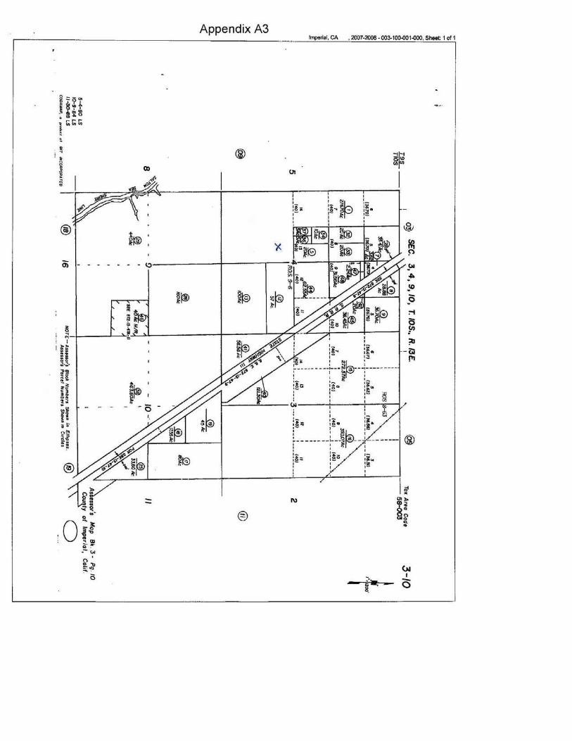
Appendix A3
IID Site Vicinity Map
1. Northwest Quarter, Sec 32, Township 9S, Range 13E 2. Southwest Quarter, Sec 4, Township 10S, Range 13E


GeothermEx, Inc. 5221 CENTRAL AVENUE, SUITE 201 RICHMOND, CALIFORNIA 94804-5829
TELEPHONE: (510) 527-9876 FAX: (510) 527-8164 E-MAIL: [email protected]
SCPPA AREA 1 GEOTHERMAL PROJECT IMPERIAL COUNTY, CALIFORNIA
DRILLING AND LOGGING PROGRAM FORTEMPERATURE-GRADIENT WELLS
for
Southern California Public Power Authority (SCPPA) Pasadena, California
by
GeothermEx, Inc. Richmond, California, USA
14 DECEMBER 2007
Appendix B

GeothermEx, Inc. 5221 CENTRAL AVENUE, SUITE 201 RICHMOND, CALIFORNIA 94804-5829
TELEPHONE: (510) 527-9876 FAX: (510) 527-8164 E-MAIL: [email protected]
1
DRILLING AND LOGGING PROGRAM FOR TEMPERATURE-GRADIENT HOLES AT SCPPA AREA 1 GEOTHERMAL PROJECT
This document describes the drilling and logging program for temperature-gradient (TG) holes to be drilled on acreage controlled by the Southern California Public Power Agency (SCPPA) near the Salton Sea, in an area referred to as Area 1 (Figure 1). GeothermEx has prepared this program pursuant to a Professional Services Agreement approved by SCPPA on 8 November 2007. SCPPA is contemplating the drilling of 2 to 3 TG holes in Area 1 to depths of approximately 2,000 feet.
1. Equipment, Materials and Procedures
Figure 2 shows the completion design for the TG holes. A rotary rig capable of drilling a 6-1/8-inch hole to 3,000 feet should be contracted to conduct the work. Figure 3 shows a drilling-pad layout suitable for such a rig.
The driller should make provision for setting the rig on firm ground, or should distribute the load of the rig using large wood mats, since the ground at some of the locations may settle with weight in extremely soft ground.
The TG hole design contemplates cementing 3 strings of casing (14-inch conductor pipe to 75 feet, 9-5/8-inch surface casing to 250 feet and 7-inch intermediate to 1,000 feet) as a precaution against the possible shallow gas flow known to have occurred while drilling other wells within or in the vicinity of Area 1. Weighted mud will be used to drill below the depth of the conductor pipe.
At the time of completion, a string of 2-7/8-inch oilfield tubing (either continuous coiled tubing or threaded API tubing), capped at the bottom, will be run inside the hole and filled with clear water. The annulus will be filled with a mixture of high-viscosity drilling mud and lost- circulation material or cement. This completion will attempt to seal any water or gas flow behind the tubing and will allow the measurement of true formation temperatures.
The procedure for drilling and completing the TG holes is presented in Appendix 1. The drilling-fluid program for the TG holes is described in Appendix 2. The logging procedure for the TG holes is presented in Appendix 3.
2. Well Depth
The anticipated depth for the TG holes is approximately 2,000 feet, but the program described herein will accommodate depths of up to 3,000 feet if this is warranted by geologic conditions encountered in the upper portions of the hole. The same basic well design will be used for all
Appendix B

GeothermEx, Inc. 5221 CENTRAL AVENUE, SUITE 201 RICHMOND, CALIFORNIA 94804-5829
TELEPHONE: (510) 527-9876 FAX: (510) 527-8164 E-MAIL: [email protected]
2
holes to be drilled in Area 1 and within this depth range. Minor adjustments to casing depths may be made during drilling based on actual rock formations encountered.
3. Casing and Cementing Program
Refer to Appendix 1 and Figures 2, 6, and 7.
4. Drilling Fluids
Refer to Appendix 2.
5. Logging
Mud logging and sample collection of rock cuttings should be conducted on a routine basis during the course of the drilling operation. After each well is completed, temperature-gradient logs will be conducted at specific time intervals. Refer to Appendix 3 for more details on the temperature-logging procedures.
6. Blowout-Prevention Equipment
Figures 4 and 5 show the details of the blowout-prevention (BOP) assemblies to be used while drilling the TG holes. Based on known and estimated conditions in Area 1, a 17-1/2-inch hole will be drilled and the 14-inch conductor pipe will be cemented in place at a depth of approximately 75 feet. A flow diverter (with a rotating head) will be adequate to drill below the 14-inch conductor pipe with a 12-1/4-inch bit up to approximately 250 feet, where the 9-5/8-inch surface casing will be cemented (Figure 4).
Before drilling the next stage (8-1/2-inch hole to approximately 1,000 ft), the driller will install an 11-inch hydraulic gate valve that can be used to shut in the well completely anytime during drilling and when the drill string is out of the hole. The casing head will be fitted with two 2-inch side valves to quench or kill the hole by injecting cold water or weighted mud, or to vent the gas pressure that may accumulate inside the well (Figure 5). The driller will also install an 11-inch expansion-type BOP (Hydrill or similar) above the 11-inch gate valve while drilling below the depth of 250 feet.
A 7-inch casing string will be cemented at a depth of approximately 1,000 feet, and the same BOP equipment described above will be used to drill the rest of the well. The last drilling stage, below the 7-inch casing shoe, will be drilled with a 6-1/8-inch bit, from 1,000 feet to total depth (2,000 – 3,000 feet).
Appendix B

GeothermEx, Inc. 5221 CENTRAL AVENUE, SUITE 201 RICHMOND, CALIFORNIA 94804-5829
TELEPHONE: (510) 527-9876 FAX: (510) 527-8164 E-MAIL: [email protected]
3
7. Geologic Prognosis
The TG holes will be drilled in an area located near the northeastern margin of the Salton Trough, which is an active basin filled with up to 20,000 feet of sediments deposited in late Cenozoic time by the Colorado River and its antecedents. The formations to be penetrated by the holes are therefore expected to consist predominantly of fluvial to deltaic deposits, which may include claystones, siltstones, sandstones and gravels. Alluvial deposits from very recent erosion will be present at the surface and at shallow depths; their lithology is expected to be generally similar to that of the underlying sediments. Lithologies reported from several of the shallow holes drilled in the area confirm that sedimentary rock is present to depths of at least 1,000 feet.
The pre-Salton-Trough rocks exposed in the Chocolate Mountains to the northeast of Area 1 consist predominantly of Paleozoic to Precambrian-age intrusive and metamorphic rocks, with lesser quantities of Tertiary volcanic and subvolcanic rocks. These formations probably underlie the Salton Trough sediments in the area of investigation; however, it is probable that they lie deeper than the levels that will be reached by the TG holes.
The rocks penetrated in the deeper part of the holes could be affected by low-grade hydrothermal alteration, as a consequence of high temperature gradients and, possibly, circulation of hydrothermal fluids. Any such alteration present at the depths being drilled is not likely to have changed the original properties of the sedimentary rocks significantly.
Shallow zones saturated with carbon dioxide gas are known to be present some distance to the south of Area 1, at and near the eastern shore of the Salton Sea geothermal field. At least one well (Kennecott 6-3) at the southern margin of Area 1 encountered carbon dioxide gas flows at a depth of 250 feet, though other wells in Area 1 have no record of shallow gas flows being a problem. The possibility of encountering shallow pressurized gas zones in the currently proposed TG holes has been reflected in the completion design and should be kept in mind while drilling.
8. Well Site Layout and Design
Refer to the description of pad preparation in Appendix 1 and Figure 3.
9. Existing and Planned Access Roads
Short new roads (probably less than 1,000 feet each) may be needed at some of the locations to gain access to the well sites.
Appendix B

GeothermEx, Inc. 5221 CENTRAL AVENUE, SUITE 201 RICHMOND, CALIFORNIA 94804-5829
TELEPHONE: (510) 527-9876 FAX: (510) 527-8164 E-MAIL: [email protected]
4
10. Groundwater Sampling
Samples of groundwater from permeable zones within a few hundred feet of the surface may be collected at selected points, for analysis to assess the characteristics of the groundwater. These samples may be collected by airlifting (if an air-assisted drilling method is being used), or by using a standard water-sampling device for water wells.
Appendix B

GeothermEx, Inc. 5221 CENTRAL AVENUE, SUITE 201 RICHMOND, CALIFORNIA 94804-5829
TELEPHONE: (510) 527-9876 FAX: (510) 527-8164 E-MAIL: [email protected]
5
Appendix 1. Drilling Procedure for Temperature-Gradient Holes in SCPPA Area 1
1. Build location and level pad where drilling rig and auxiliary equipment will be installed (see Figure 3).
2. Build 4 ft x 4 ft x 4 ft cellar according to rig specifications, with sufficient depth to accommodate wellhead equipment and drilling valve under the ground level.
3. Prepare drill pad according to driller’s specifications. Dig out mud disposal pit (if required) according to driller's instructions.
4. Move in and rig up drilling rig and auxiliary equipment.
5. Rotary drill 17-1/2-inch hole to approximately 75 feet. Install and cement 14-inch conductor pipe using ready-mix truck and dumping cement from the surface. Install mud diverter and rotating head (Figure 4).
6. Start mud logging. Collect samples of the rock cuttings every 10-20 feet, depending on the geologist’s requirements and the rate of penetration.
7. Rotary drill 12-1/4-inch hole to approximately 250 feet using the following bottom-hole assembly:
� 12-1/4-inch bit,
� Bit sub with flapper valve,
� Near-bit stabilizer
� 1 x 8-inch drill collar,
� 12-1/4-inch string stabilizer,
� 9 x 8-inch drill collars,
� Cross-over sub
� 3-1/2-inch drill pipe.
8. Run 9-5/8-inch, 40 lb/ft, K-55, BTC surface casing to an approximate depth of 250 feet. Cement casing in place using a cementing company. Refer to Figure 6 for details on the cement slurry.
9. Allow cement to cure for a period of 16-24 hours. Cut casing to desired length and weld on 11-inch casing head flange with 2 x 2-inch valved outlets. Pressure rating of the side
Appendix B

GeothermEx, Inc. 5221 CENTRAL AVENUE, SUITE 201 RICHMOND, CALIFORNIA 94804-5829
TELEPHONE: (510) 527-9876 FAX: (510) 527-8164 E-MAIL: [email protected]
6
valves should be at least 1,000 psi, in order to be compatible with the casing testing pressure (750 psi).
10. Install and test 11-inch hydraulic gate and 11-inch annular BOP – Hydril or similar – (Figure 5). The annular BOP, hydraulic gate and casing shall be tested with water as a testing fluid at a minimum pressure of 750 psi for a period of 15 minutes. Record test pressures utilizing a chart or electronic pressure recorder. Notify the California Division of Oil, Gas, and Geothermal Resources (DOGGR) 24 hours prior to the test.
11. Rotary drill 8-1/2-inch hole to approximately 1,000 feet using the following bottom-hole assembly:
� 8-1/2-inch bit,
� Bit sub with flapper valve,
� Near-bit stabilizer
� 1 x 6-inch drill collar,
� 8-1/2-inch string stabilizer,
� 9 x 6-inch drill collars,
� Cross-over sub
� 3-1/2-inch drill pipe.
12. Run 7-inch, 23 lb/ft, K-55, BTC surface casing to an approximate depth of 1,000 feet. Cement casing in place using a cementing company. Refer to Figure 7 for details on the cement slurry.
13. Allow cement to cure for a period of 16-24 hours. Cut casing to desired length and weld on 7-inch casing-head flange with 2 x 2-inch valved outlets.
14. Install and test 11-inch hydraulic gate valve and 11-inch annular BOP – Hydril or similar – (Figure 5). The annular BOP, hydraulic gate valve and casing shall be tested with water as a testing fluid at a minimum pressure of 750 psi for a period of 15 minutes. Record test pressures utilizing a chart or electronic pressure recorder. Notify DOGGR 24 hours prior to the test.
15. Drill out cement inside casing with 6-1/8-inch using a steel-tooth bit. Pull out and use the following assembly to drill the rest of the hole:
Appendix B

GeothermEx, Inc. 5221 CENTRAL AVENUE, SUITE 201 RICHMOND, CALIFORNIA 94804-5829
TELEPHONE: (510) 527-9876 FAX: (510) 527-8164 E-MAIL: [email protected]
7
� 6-1/8-inch bit,
� Bit sub with flapper valve
� 6-1/8-inch near-bit stabilizer
� 1 x 4-1/2-inch drill collar
� 6-1/8-inch string stabilizer
� 1 x 4-1/2-inch drill collar,
� 6-1/8-inch string stabilizer (optional for crooked hole condition),
� 6 x 4-1/2-inch drill collars
16. Drill a 6-1/8-inch diameter hole to an anticipated depth of 2,000 feet (maximum depth 3,000 ft) using mud as drilling fluid. If fluid return temperature exceeds 170ºF, be prepared to install a mud cooler in the circulating system.
17. If partial losses of circulation occur, attempt curing losses with lost-circulation material (LCM). If loss volume increases with time to a difficult level, attempt to cure losses with cement plugs.
18. Run electrical logs (optional) and a temperature/pressure survey at the end of drilling (see Appendix 3).
19. Run a string of 2-7/8-inch (N-80) used oilfield tubing (either coiled or API tubing), equipped with a cap at the bottom. Fill annular space with a mixture of high-viscosity drilling mud and LCM; top up the upper portion of the annulus (3 feet) with cement to the surface.
20. Nipple down BOP and drilling valve. Install permanent tubing ball valve on surface. Fill tubing to the surface with clear water. Keep valve closed except during logging. Begin logging temperature recovery in the well as per logging program (Appendix 3).
21. Clean up the well site and restore surrounding area to natural conditions. Move rig to the next well site.
Appendix B

GeothermEx, Inc. 5221 CENTRAL AVENUE, SUITE 201 RICHMOND, CALIFORNIA 94804-5829
TELEPHONE: (510) 527-9876 FAX: (510) 527-8164 E-MAIL: [email protected]
8
Appendix 2. Drilling Fluid Program for Temperature-Gradient Holes in SCPPA Area 1
The final mud characteristics will be determined using standard API (American Petroleum Institute) approved testing techniques, and the treatment of the same will be decided at the site. As a guideline, the following mud characteristics should be maintained:
a) Mud Return Temperature <40°C (100 ºF):
Weight S.G. 1.05 - 1.07 (8.8 - 8.9 ppg)
pH 9 - 10
Marsh viscosity 40 - 50 seconds
Plastic viscosity 5 - 10 cp
Yield point 15 - 25 lbs/100 sq.ft.
10 min Gel 15-lbs/100 sq.ft.
Water loss 10-cc/30 min.
Wall cake 0.5 - 1.0mm (1/32")
Sand content 0.25% max. (Control with desander/desilter)
b) Mud Return Temperature >40°C (100ºF):
Weight S.G. 1.03 - 1.05 (8.6 – 8.8 ppg)
pH 9 - 10
Marsh viscosity 40 seconds
Plastic viscosity 5 - 10 cp
Yield point 5 - 10 lbs/100 sq.ft.
10 min Gel 2-5 lbs/100 sq.ft.
Water loss 8-10 cc/30 min..
Wall cake 0.5 - 1.0mm (1/32")
Sand content 0.25% max. (Control with desander/desilter)
Appendix B

GeothermEx, Inc. 5221 CENTRAL AVENUE, SUITE 201 RICHMOND, CALIFORNIA 94804-5829
TELEPHONE: (510) 527-9876 FAX: (510) 527-8164 E-MAIL: [email protected]
9
c) Weighted Mud (at any depth):
Weight S.G. 1.26 - 1.38 (10.5 – 11.5 ppg)
pH 9 - 10
Marsh viscosity 40-50 seconds
Plastic viscosity 14 cp
Yield point 10 lbs/100 sq.ft.
10 min Gel 5 lbs/100 sq.ft.
Water loss 8-10 cc/30 min..
Wall cake 1.0mm (1/32")
Sand content 0.25% max. (Control with desander/desilter)
Appendix B

GeothermEx, Inc. 5221 CENTRAL AVENUE, SUITE 201 RICHMOND, CALIFORNIA 94804-5829
TELEPHONE: (510) 527-9876 FAX: (510) 527-8164 E-MAIL: [email protected]
10
Appendix 3.
Procedure and Schedule for Logging Temperature-Gradient Holes in SCPPA Area 1
Once total depth has been reached, and before installing 2-7/8-inch tubing, it may be desirable to run electrical logs for purposes of lithologic correlation between wells. The electrical log suite (if run) should include a gamma-ray log and a compensated-neutron formation-density log. The decision as to whether to run electrical logs can be based on the cost of quotations received from commercial logging companies.
A temperature and pressure survey should be run before the 2-7/8-inch tubing is installed. This survey may be run either with surface-read-out electric-line tools, with memory-based electric tools, or with Kuster-type mechanical tools of appropriate temperature range. The choice oflogging tools will depend on cost and contractor availability.
After the 2-7/8-inch tubing has been installed, repeated temperature surveys should be conducted at the schedule described in the table below, to track the recovery of temperatures from the cooling effects of drilling. It is anticipated that these surveys will be run with Kuster mechanical-type temperature tools, to minimize cost. At each gradient hole site, the temperature tool will be lowered inside the tubing using a spooling device and a mechanical hoist equipped with a depth indicator marked in feet. A metal bar will be attached above the temperature tool to provide sufficient weight and to prevent the wire from getting tangled inside the tubing.
The following procedure will be used to conduct the temperature-gradient measurements:
1. After completing the well, fill the cellar space with concrete up to ground level. Build a 1-ft x 1-ft x 1-ft concrete slab around the tubing (above ground level) to prevent surface water from accumulating around the tubing and causing corrosion.
2. Fill the capped tubing to the top with clean water. Cut off the tubing 1 ft above the level of the concrete slab. Make up an NPT thread in the upper end of the tubing and install a 3-inch ball valve. Build a concrete or metal shelter above the tubing to protect it from possible vandalism or accidental damage.
3. Allow at least three days after well completion for temperature stabilization, before making the first temperature measurement.
4. Install a top sheave above the 3-inch valve and secure it to the tubing with a tubing clamp.
5. Make up wire line around the sheave and set the counter on “zero” at ground level.
6. Log while lowering the temperature tool into the well. Start lowering the wire making 5-minute stops every 50 ft (or at smaller intervals).
Appendix B

GeothermEx, Inc. 5221 CENTRAL AVENUE, SUITE 201 RICHMOND, CALIFORNIA 94804-5829
TELEPHONE: (510) 527-9876 FAX: (510) 527-8164 E-MAIL: [email protected]
11
7. If the wire stops while descending inside the tubing, pick up 2-5 ft of wire and let the wire descend on free fall. Make several attempts to pass through the obstruction.
8. If not successful, pull out and replace the weight bar with a solid metal bar about 6 ft long. The bottom of the bar should have a sharp point to enable penetration of any soft obstruction.
9. Once the well has been logged to bottom, pull out the wire (preferably by hand if a restriction was detected during the trip down).
10. Follow the timetable indicated below to schedule the temperature measurements in each well.
FirstMeasurement
Three days after well completion
Allow cooling effects from drilling mud to disappear
SecondMeasurement
10 days after well completion
If cooling effects are still visible, skip next measurement
ThirdMeasurement
15 days after well completion
Check for temperature stabilization. If temperature has stabilized, skip next
measurement.
FourthMeasurement
20 days after well completion Check for temperature stabilization
FifthMeasurement
30 days after well completion
If temperature measurements are within ± 2°C of the previous log, skip next
measurement
SixthMeasurement
60 days after well completion Check for stabilization
SubsequentMeasurements
Final confirmation measurement, 90 days after well completion
Schedule additional measurements if stabilization is not reached
Appendix B

App
endi
x B

7-inch, ANSI 300 drilling valveattached to conductorcasing head
2-inch valves, rated for 1,000 psi
4 FT x 4 FT x 4 FT Cellar
14-inch Conductor Pipeat 75 feet
12-1/4-inch hole9-5/8-inch, 40 lb/ft, K-55, BTCsurface casing cemented at 250 ft
8-1/2-inch hole7-inch, 23 lb/ft, K-55, BTCintermediate casing cemented at 1000 ft
At completion, hole annulus to befilled with a mixture of highviscosity mud, LCM, etc.or cemented through the annulus
2-7/8-inch (OD), N-80used coiled tubing or API tubingcapped at bottom
6-1/8-Inch hole drilledto TD (2,000 - 3,000 ft)
Figure 2Salton Sea (Area 1) Geothermal Field
EXPLORATORY TEMPERATURE GRADIENT HOLE
GeothermEx, Inc.2007
Appendix B

Figu
re 3
. D
rilli
ng P
ad L
ayou
t (N
ot to
Sca
le)
30 ft
Res
erve
Pit
(Mud
and
Roc
k C
uttin
gs)
Was
te W
ater
R
eser
ve P
it
Partition
Mud
Pit
#1
10 ft
X 4
0 ft
Mud
Pit
#210
ft X
40
ft
Sub
stru
ctur
e an
d D
erric
k25
ft X
50
ft
Mud Pump #115 ft X 40 ft
Wat
er T
ank
10 ft
X 4
0 ft
BO
P P
ress
ure
Acc
umul
ator
10 ft
X 3
0 ft
Spa
re P
art
Sto
rage
10 ft
X 2
5 ft
75 ft
Pip
e R
amp
Pip
eR
acks
Tool
Pus
her
Sup
ervi
sor
Trai
lers
Are
a fo
r A
ccum
ulat
ion
ofO
rgan
ic S
oil
150
ft
100
ft
Wel
l Cen
ter
Man
euve
ring
Are
a Dril
ling
Pad
A
cces
s
MudSeparator
2007
Geo
ther
mEx
, Inc
.
App
endi
x B

Adaptor flange (if required)
Figure 4. Equipment for Drilling Below Conductor Pipe
14" Flow Diverter
14"steel conductor
pipe
Flowline (with Valve)
Kill line(with valve)
Fill-up Line(with valve)
Choke (with valve)
13-5/8"Rotating Head
GeothermEx, Inc. 2007
Appendix B

GeothermEx, Inc. 2007
Figure 5. Blowout Prevention Equipment for Drilling Below 9-5/8-inch Casing
11" 3M ANSI 900
Annular Preventor
11" 3MANSI 900
Rotating Head(Optional)
11" 2M ANSI 600
Hydraulic Gate
11"- 400 x 11"- 600 DSA Flange
9-5/8"casing
9-5/8" x 11" ANSI 400
Casing head with2 x 2-1/16" side outlets
Appendix B

200100
050
0.041670.42574
14" Surface Csg. 0.3353875 0.31319
1.341.156.3 Lead Water gal/sk5.0 Tail Water gal/sk
14.8 Lead Cement Weight (lbs/gal)15.8 Tail Cement Weight (lbs/gal)
(ft3)
53.8725.1553.870.00
(ft3)
62.6431.3217.03
(ft3)
132.89110.99
Float Collar 243.88207
(ft3)
Float Shoe 88.13247 8.63
Bottom 12-1/4" Hole (lbs) (sks)250 9,322.19 99.17
9,071.95 96.51Total Cement 18,394.14 195.68
Casing Details : (bbl) (gal)
Tack-weld bottom three joints. Run centralizers as recommended by 14.88 624.79cement engineer 11.49 482.55
26.37 1,107.34Cement Details :Pump 200 cu. ft of water ahead, followed by 100 cu. ft of pre-flush.
Do not reciprocate casing while cementing.
Do not exceed 1,500 psi while cementing or displacing.
Pressure-test all lines to 2,000 psi before starting cement operation.
Use Class "G" cement, pre-hydrated gel, silica flour, cement retarder,
friction reducer and defoamer as recommended by cementing operator. GeothermEx, Inc. 2007
Total Water
Slurry WaterLead CementTail Cement
Stab-in Method
Cement WeightLead CementTail Cement
Total Tail SlurryTotal Slurry for the Job
Displacement Water VolumesWiper Plug Method
Excess Tail SlurrySlurry in Float Shoe/Collar
Calculated TotalsTotal Lead Slurry
Excess Lead Slurry in Open HoleExcess Lead Slurry in Cased Hole
Tail Slurry CalculationsCalculated Tail Slurry
Tail Cement Yield (ft3/sk)
Lead Slurry CalculationsCalculated Lead Slurry in Open HoleCalculated Lead Slurry Bet. Csngs.
Casing Capacity (ft3/ft)Volume Between Casings (ft3/ft)
Volume Bet.Csg & Open Hole (ft3/ft)Lead Cement Yield (ft3/sk)
% Excess Lead Cement in Open Hole% Excess Lead Cement in Cased Hole% Excess Tail Cement in Open Hole
Drill Pipe Capacity (ft3/ft)
Cement WorksheetInitial Parameters
Feet of Tail Cement
Figure 6. Cementing Calculations for 9-5/8-inch Casing
Appendix B

9-5/8" Surface250
300100
050
0.041670.221030.158480.12681
1.341.156.3 Lead Water gal/sk5 Tail Water gal/sk
14.8 Lead Cement Weight (lbs/gal)15.8 Tail Cement Weight (lbs/gal)
(ft3)
94.7339.6294.730.00
(ft3)
38.0419.028.84
(ft3)
229.0765.91
Float Collar 294.98957
(ft3)
Float Shoe 211.53997 39.88
Bottom 8-1/2" Hole (lbs) (sks)1,000 16,069.38 170.95
5,387.07 57.31Total Cement 21,456.45 228.26
Casing Details : (bbl) (gal)
Tack-weld bottom three joints. Run centralizers as recommended by 25.64 1076.99cement engineer 6.82 286.55
32.47 1363.54Cement Details :Pump 200 cu. ft of water ahead, followed by 100 cu. ft of pre-flush.
Do not reciprocate casing while cementing.
Do not exceed 1,500 psi while cementing or displacing.
Pressure-test all lines to 2,000 psi before starting cement operation.
Use Class "G" cement, pre-hydrated gel, silica flour, cement retarder,
friction reducer and defoamer as recommended by cementing operator. GeothermEx, Inc. 2007
Figure 7. Cementing Calculations for 7-inch, 23 lb/ft Casing
Cement WorksheetInitial Parameters
Feet of Tail Cement% Excess Lead Cement in Open Hole% Excess Lead Cement in Cased Hole% Excess Tail Cement in Open Hole
Drill Pipe Capacity (ft3/ft)Casing Capacity (ft3/ft)
Volume Between Casings (ft3/ft)Volume Bet.Csg & Open Hole (ft3/ft)
Lead Cement Yield (ft3/sk)Tail Cement Yield (ft3/sk)
Lead Slurry CalculationsCalculated Lead Slurry in Open HoleCalculated Lead Slurry Bet. Csngs.Excess Lead Slurry in Open HoleExcess Lead Slurry in Cased Hole
Tail Slurry CalculationsCalculated Tail Slurry
Excess Tail SlurrySlurry in Float Shoe/Collar
Calculated TotalsTotal Lead SlurryTotal Tail Slurry
Total Slurry for the Job
Displacement Water VolumesWiper Plug Method
Stab-in Method
Cement WeightLead CementTail Cement
Total Water
Slurry WaterLead CementTail Cement
Appendix B

Appendix C

Appendix C

Appendix C

Appendix C

Appendix C

Appendix C

Appendix C

Appendix C

Appendix D

Appendix E

Appendix E

Appendix E

Appendix F