pre-fi lled cpu xpandable liquid cooling ek-xlc predator … · ek-xlc predator 240 4 ek-xlc...
TRANSCRIPT

EK-XLC PREDATOR 240 360Pre-fi lled CPU Xpandable Liquid Cooling
USEr gUIDE
For EK-XLC Predator (r1.1) series units | 3rd revision, Dec 1st 2015


/ 1 /
EK Water Blocks bears the name of its founder Edvard König, who started experimenting with liquid cooling in 1999. From the humble be-ginnings in the early years of the previous decade, the company grew steadily to become a global premium liquid cooling gear manufacturer. Today, EKWB offers a complete range of products for liquid cooling, from a renowned Supremacy line of CPU water blocks, to a wide range of CoolStream radiators, from in-house developed Vardar High pressure fans, to market-proven DDC series of liquid cooling pumps and thus provides overclocking enthusiasts and PC builders with the best of what the market can offer. Predator all-in-one eXpandable Liquid Cooling so-lution is the next step to bring extreme liquid cooling performance in the hands of dedicated gamers and PC enthusiasts around the world.
Welcome to EK-World!
Safety precautions 1. Keep and store the product away from the reach of children.2. Check the component list and condition of the product before installation.
If there is any problem, contact the shop where you have purchased the problem to get a replacement or refund.
3. EKWB d.o.o. is not responsible for any damages due to external causes, including but not limited to, improper use, problems with electrical power, accident, neglect, alteration, repair, improper installation and improper testing.
4. CPU and motherboard are subject to damage if the product is incorrectly installed.
5. This product is All-In-One eXpandable CPU liquid cooling solution. Disassembling it and combining with parts, other than EK Water Blocks products, may lead to warranty loss.
6. Product warranty period is 24 months.

/ 2 /
RADIATOR SPACE CONSTRAINT REQUIREMENTS 4EK-XLC PrEDATOr 240 4EK-XLC PrEDATOr 360 (InCL. QDC) 5
UNIT ORIENTATION LIMITATIONS 6ELECTRICAL CONNECTIONS 7
COnnECTIng THE HUB TO THE POWEr SUPPLy 7COnnECTIng THE HUB TO THE mOTHErBOArD 7
INSTALLING THE PUMP/FAN/RADIATOR UNIT 8GENERAL INFORMATION ON WATERBLOCK COMPATIBILITY 9INSTALLING THE WATER BLOCK 10
LgA-2011(-3) SOCKET mOTHErBOArDS 10LgA-115X SOCKET mOTHErBOArDS 11
MAINTENANCE 21FREQUENTLY ASKED QUESTIONS 21TROUBLESHOOTING 23
In CASE OF CPU OVErHEATIng 23THE COOLEr IS TOO LOUD 24
GENERAL LIQUID COOLING PARTS CLEANING GUIDE 24PrEVEnTIVE STEPS 25
PART SPECIFICATION LIST 26PUmP XyLEm DDC – 3.1 26FITTIngS 26FAn SPLITTEr HUB 27FAnS 28THErmAL grEASE 28TUBIng 28
SUPPORT AND SERVICE 30SOCIAL MEDIA 30
QUICK INSTALLATION GUIDE
SCOPE OF DELIVERY 3REQUIRED TOOLS 3VIDEO INSTALLATION GUIDES 3
POSSIBILITIES OF EXPANDING THE SYSTEM 14EK-XLC PREDATOR 240 14
Disassembly 14Adding components to the loop 15Filling up the system 15Adding an external reservoir (OPTIOnAL) 1 7
EK-XLC PREDATOR 360 (INCL. QDC) 18Preparing the predator unit 18Connecting the pre-filled water block/radiator unit 19Adding an external reservoir (OPTIOnAL) 20
INSTALLING TRANSPARENT TUBING (OPTIONAL) 20
TABLE OF COnTEnT

/ 3 /
SCOPE OF DELIVEry
EK-XLC Predator 360 (incl. QDC) EK-XLC Predator 240OR
All-in-one expandable liquid cooling unit
Thermal grease Installation manual
rEQUIrED TOOLS
Phillips-head screwdriver
VIDEO InSTALLATIOn gUIDES
Our offi cial youTube channel features video installation guides, that can help you with Predator installation. Scan the Qr code to visit our youTube channel.
CPU Backplate mechanism CPU mounting mechanism

/ 4 /
rADIATOr SPACE COnSTrAInT rEQUIrEmEnTS
68 mm (2,68 in)
133 mm (5,24 in) 2
95 m
m (1
1,61
in)
120
mm
(4,7
2 in
)
15
mm
(0,5
9 in
)
EK-XLC PREDATOR 240
Water block
radiator
Pump

/ 5 /
Contents:
The following items are enclosed with each EK-Supremacy mX water block:
- EK-Supremacy mX universal CPU water block /w pre-installed Insert I2 and Jet J1 (0.25mm)(all around great performer)o Pre-installed mounting mechanism- EK-Supremacy mX Backplateo Backplate BAS gasketo Backplate for Intel LgA-115x socket motherboards- Torx key T20- EK-TIm Ectotherm 1g thermal grease
EK-XLC PREDATOR 360 (INCL. QDC)
68
mm
(2,6
8 in
)
133
mm
(5,2
4 in
)
415 mm (16,34 in) 15 mm (0,59 in)
120 mm (4,72 in)
Water block
radiator
QDC
Pump
/ 6 /
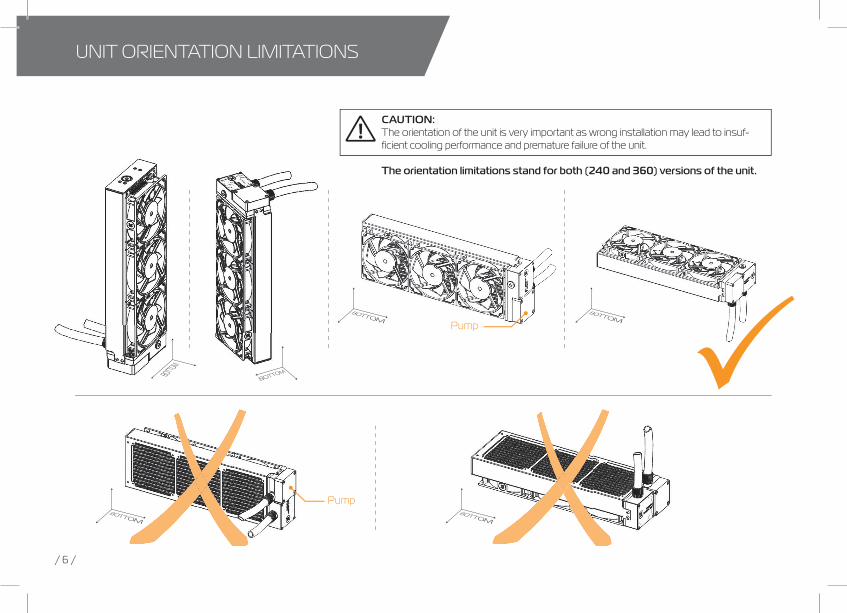
CAUTION:The orientation of the unit is very important as wrong installation may lead to insuf-fi cient cooling performance and premature failure of the unit.
The orientation limitations stand for both (240 and 360) versions of the unit.
UnIT OrIEnTATIOn LImITATIOnS
Pump
Pump

/ 7 /
ELECTrICAL COnnECTIOnS
CONNECTING THE HUB TO THE POWER SUPPLYSTEP 1.: Take the enclosed power cable and plug the two-pin PCI-express minifit power connector to the fan splitter hub.
STEP 2.: Use the SATA POWEr connector at the other end and plug it to the female connector found on the main power supply.STEP 2STEP 1
CONNECTING THE HUB TO THE MOTHERBOARD In order to obtain the PWm fan speed control you must follow the steps below:
STEP 3.: Take the enclosed connection cable and plug the two-pin cable connector to the fan splitter hub.
STEP 4.: Use the 4-pin connector at the other end and plug it to the male connector header located on the motherboard. Always use CPU-dedicated fan headers if possible.
Always use CPU fan header. On majority of motherboards these headers usually offer best PWm regulation.
STEP 4STEP 3

/ 8 /
InSTALLIng THE PUmP/FAn/rADIATOr UnIT
STEP 1mounting of the pump/fan/radiator unit requires special attention.
Please take the unit and fi nd the enclosed standard fan mounting screws. you will need 8 screws for 240mm version or 12 screws for 360mm version.
you will need a philips-head screwdriver which is not enclosed in the package.
STEP 2Prepare your suitably-sized PC chassis for installation of EK-XLC Predator.
The position of the unit in the chassis depends on the size, fan mounting holes and the hardware you have installed.
you must make sure that the unit fi ts into the chassis. Usually the chassis have standard fan mounting holes pre-drilled so you should look for holes with spacing of 105mm. (A standard computer cooling 120mm fan)
Out-of-the box, the Predator is set to work in overall hot air exhaust (by placing the radiator on the exhaust) confi guration. This results in overal decrease of temperature throughout the entire computer chassis but also leads to slightly higher liquid temperatures. A reversed air fl ow is a viable option but one should always strive to achieve unidirectional fl ow of air throughout the chassis. See page 21, chapter Frequently Asked Questions, on how to change fan orientation.
STEP 3When you have selected the mounting position within the chassis you must align the Predator cooling fan mounting holes with the ones on the chassis.
Use enclosed self-tapping screws to fi rmly install the unit. Self-tapping screws re-quire more torque than threaded screws, but overall do not exaggerate with the force applied.
Check again that the unit isn’t touching the chassis anywhere except at the mounting region. Some unwanted noise may occur if the vibrations are transferred from the unit to the pc chassis.
STEP 1
STEP 2 STEP 3

/ 9 /
gEnErAL InFOrmATIOn On WATErBLOCK COmPATIBILITy
WHAT IS EnCLOSED
The following items are enclosed with EK-XLC Predator water block:
- EK-XLC Predator CPU water block - PreciseMount universal CPU mounting mechanism:
• m4 threaded thumb screws (4 pcs)• LgA-2011 m4 threaded mounting studs (4 pcs)• Springs (4 pcs)• m4 threaded thumb nuts (4 pcs)• Washers (4 pcs)
- EK-Supremacy Backplate• Backplate for Intel LgA-115x socket motherboards with rubber gasket
This CPU liquid cooling unit is pre-assembled for use with modern Intel desktop socket type motherboards. By default (out of the box) this water block supports the following CPU sockets:
- Intel® Socket LGA-775- Intel® Socket LGA-115x- Intel® Socket LGA-1366- Intel® Socket LGA-2011(-3)
narrow server type LgA-2011 is not supported by default – a mounting plateSupremacy LgA-2011 narrow ILm (EAn: 3830046990600) is mandatory to install this water block on narrow server type LgA-2011 motherboards.replacing the mounting plate requires disassembly of the water block.

/ 10 /
LGA-2011(-3) SOCKET MOTHERBOARDS
STEP 1Prepare the foil bag with mounting mechanism, which is enclosed with the EK-XLC Predator block delivery.
Install four (4) specific LgA-2011 m4 thumb screws into four m4 threaded stubs on the LgA-2011 socket integrated latch mechanism (ILm). The screws are to be installed using no tools (i.e. pliers).
It is recommended to remove the motherboard form the PC chassis before proceeding with installation of the CPU water block because of the space constraint limitations of various computer cases.
STEP 2
Cleaning the CPU: Wipe the CPU’s contact surface (by using non–abrasive cloth or Q-tip, as shown on sample photo).
Applying thermal compound: EK recommends blob or line method of applying the enclosed EK-TIm Ectotherm thermal compound to the CPU heat spreader (IHS) - see sample photo on right.
The quantity of about two rice grains is just about right. There is no need to cover the whole IHS. Applying too much thermal grease will have negative impact on the cooling performance!
STEP 2
non-abrasive cloth
Therm
al gre
ase
IHS
STEP 1
LgA-2011 m4 Thumb Screw
LgA-2011 m4 Thumb Screw
InSTALLIng THE WATEr BLOCK

/ 11 /
STEP 3
STEP 3.: Align the water block over the mounting screws on the LgA-2011(-3) motherboard with pre-installed CPU.
Before proceeding with the installation It is mandatory to remove the protective foil from the backside of the water block.
Place an enclosed compression spring and thumb nut over each m4 thumb screw. Start fastening two thumb nuts at a time, preferably in cross pattern and do not tighten them fully until all of them are partially screwed in. Then - using your fi ngers only - screw in all four thumb nuts until you reach the end of the thread. Do not use any tools (such as pliers) during this process
your EK-XLC Predator installation on LgA 2011(-3) platform is now complete.
Starting your computer up:Before you add the power to your computer please check if everything is installed according to the installation manual.
When turning on the computer be careful nothing is leaking and that the temperatures of the CPU are normal. It is best practice to enter BIOS/UEFI and check hardware health monitoring section on initial boot!
LGA-115x SOCKET MOTHERBOARDSSTEP 1If already installed, please remove the motherboard from your computer and place it on an even surface with front facing down.
STEP 2Preparing backplate rubber gasketThe enclosed rubber gasket is essential part of the backplate and mounting system and must be used every time you install this water block on your motherboard.
The rubber gasket has a partially cut inner part which needs to be re-moved when installed on Intel LgA-115x motherboard. The rubber is held on four places and can be peeled away with hand. STEP 2STEP 1
Outer part
Inner core (removable)

/ 12 /
STEP 3Install backplate rubber gasket and place metal backplate for Intel LgA-115x socket to the back of your motherboard rIBBED SIDE UP! (facing away from the motherboard) Align the holes on the motherboard with holes on rubber gasket and backplate.
make sure to orientate the rubber gasket to fi t past the CPU socket ILm backplate.
Carefully rotate motherboard assembly with front side facing up with one hand while holding the backplate and rubber in place with the other hand.
STEP 4Install four (4) m4 thumb screws onto your motherboard. It is mandatory to put 0.7mm plastic washer underneath each of the m4 thumb screws. Tighten the screws to the metal backplate until you reach the end of the thread. Using tools (such as pliers) is not recommended.
STEP 5Cleaning the CPU: Wipe the CPU’s contact surface (by using non–abrasive cloth or Q-tip, as shown on sample photo).
Applying thermal compound: EK recommends blob or line meth-od of applying the enclosed EK-TIm Ectotherm thermal compound to the CPU heat spreader (IHS) - see sample photo on right.
The quantity of about two rice grains is just about right. There is no need to cover the whole IHS. Applying too much thermal grease will have negative impact on the cooling performance!
STEP 3 STEP 4
rubber gasket
motherboard
metal Backplate m4 Thumb
Screw
PVC washer
STEP 5
non-abrasive cloth
Thermal grease
IHS

/ 13 /
STEP 6Align the water block over the mounting screws on the LgA-115x moth-erboard with pre-installed CPU.
Place an enclosed coiled spring and thumb nut over each m4 thumb screw. Start fastening two thumb nuts at a time, preferably in cross pat-tern and do not tighten them fully until all of them are partially screwed in. Then – using your fingers only screw in all four thumb nuts until you reach the end of the thread.
STEP 7Install the CPU water block along with the motherboard back into the computer chassis.
The installation of the water block is now complete.
STEP 7
STEP 6
Thumb nutCoiled spring

/ 14 /
POSSIBILITIES OF EXPAnDIng THE SySTEm
EK-XLC PREDATOR 240The EK-XLC Predator 240 is capable to cope with expansion of the system with one additional waterblock, radiator and reservoir (optional).
yOU mAy nEED TO rEmOVE COmPLETE UnIT FrOm yOUr COmPUTEr CHASSIS!
For the expansion you will need (recommended):- A additional waterblock/reservoir- Tubing: EK-Tube ZMT Matte Black 15,9/9,5mm (EAn: 3830046999207)- Fittings: EK-ACF Fitting 10/16mm (EAn: 3831109846452) - Coolant: EK-Ekoolant EVO CLEAR (Premix 1l) (EAn: 3830046999689)- EK-ATX Bridging Plug (EAn: 3831109867716)
required tools:- A pair of scissors (to cut the tube to size)- 6mm Allen key (usually enclosed with the waterblock)
Before undertaking the following steps it is advised to have a suitable plas-tic container and some paper towels on hand in order to prevent coolant spillage
STEP 1.: We recommend that you drain the loop through the fi tting on the CPU waterblock. Unscrew the fi tting compression ring in counter-clockwise direction.
STEP 2.: gently pull the tube off the fi tting. Before you do that it is a good practice to put the cup under the tube and fi tting for the purpose of safe draining procedure. you can tilt the whole unit to let all the coolant out of the system.STEP 1 and 2
2
1

OPTIONAL
/ 15 /
Take the additional liquid cooling component (water block of any type, radiator...) and mount it according to its installation manual. To connect it to the EK-XLC Pred-ator 240 unit please follow the steps below:
STEP 3.: Connect the loose tube from Predator unit to the 10/16 fi tting on the additional water block.
STEP 4.: make sure that the tube sits fi rmly on the fi tting barb and then tighten the compression ring using your hands only. Do not use any tools (i.e. pliers) during this process.
If the present tube is not long enough you will have to cut a new-longer one.
STEP 5.: measure the length of the tube that is needed to connect the water blocks together. you can use a pair of scissors or a knife to cut the tube.
STEP 6.: Attach the tube onto the both fi tting barbs until it sits fi rmly. Secure the fi tting’s compres-sion ring to make the assembly complete. Check again that all of the tubing is secured by compression fi ttings as intended.
Filling up the system:Before starting to fi ll the system you should prepare some paper towels in case of dripping. In order to fi ll up successfully please follow the steps below.
STEP 7.: Use 6mm Allen key (supplied with every EK water block) to unscrew the plug on the back-side of the Predator unit radiator.
STEP 8.: Start fi lling process by adding coolant through the port on the back of the unit as shown on the picture on STEP 8. Pour the coolant slowly until the unit is full then shake it a bit to get out as much air as possible. you can alternatively screw the plug in and rotate the unit in multiple directions and then repeat the procedure until there is no air left in the unit.
It is essential to get as much air as possible out of the system at this stage!
STEP 3 and 4
STEP 7 and 8
nut
Barb
STEP 5 and 6
OPTIONAL
/ 16 /
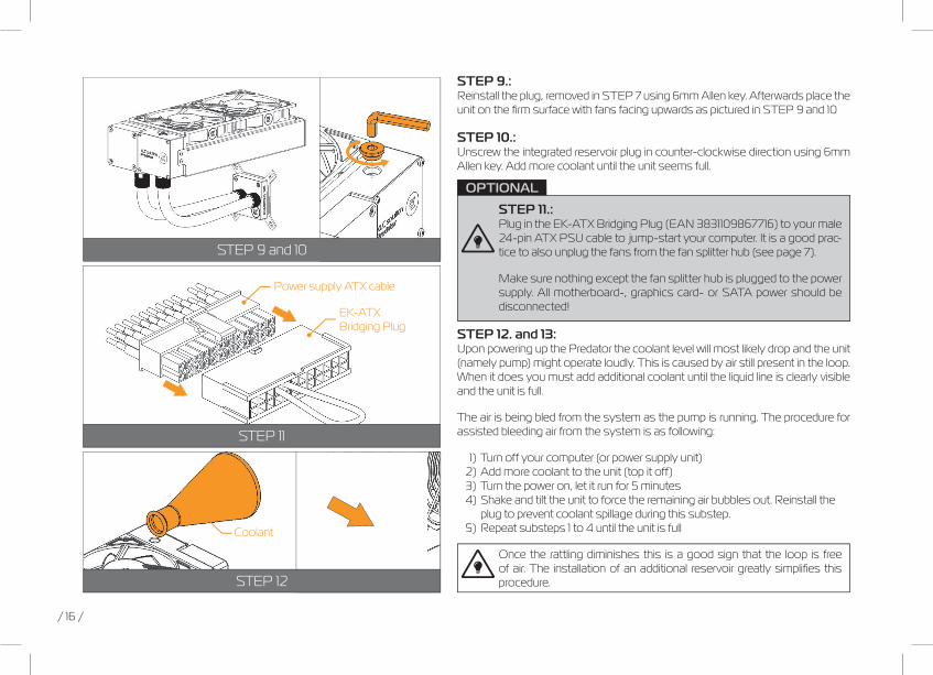
STEP 9.: reinstall the plug, removed in STEP 7 using 6mm Allen key. Afterwards place the unit on the fi rm surface with fans facing upwards as pictured in STEP 9 and 10
STEP 10.: Unscrew the integrated reservoir plug in counter-clockwise direction using 6mm Allen key. Add more coolant until the unit seems full.
STEP 11.: Plug in the EK-ATX Bridging Plug (EAn 3831109867716) to your male 24-pin ATX PSU cable to jump-start your computer. It is a good prac-tice to also unplug the fans from the fan splitter hub (see page 7).
make sure nothing except the fan splitter hub is plugged to the power supply. All motherboard-, graphics card- or SATA power should be disconnected!
STEP 12. and 13: Upon powering up the Predator the coolant level will most likely drop and the unit (namely pump) might operate loudly. This is caused by air still present in the loop. When it does you must add additional coolant until the liquid line is clearly visible and the unit is full.
The air is being bled from the system as the pump is running. The procedure for assisted bleeding air from the system is as following:
1) Turn off your computer (or power supply unit) 2) Add more coolant to the unit (top it off) 3) Turn the power on, let it run for 5 minutes 4) Shake and tilt the unit to force the remaining air bubbles out. reinstall the plug to prevent coolant spillage during this substep. 5) repeat substeps 1 to 4 until the unit is full
Once the rattling diminishes this is a good sign that the loop is free of air. The installation of an additional reservoir greatly simplifi es this procedure.
STEP 9 and 10
STEP 11
STEP 12
EK-ATX Bridging Plug
Power supply ATX cable
Coolant

OPTIONAL
/ 17 /
STEP 14.:It is always a good practice to conduct a 24-hour leak test to ensure the system is leak free and safe to use.
Upon completing the leak test please reinstall the liquid cooling unit back into your computer chassis.
Before you add the power to your computer please check if everything is installed according to the installation manual.
STEP 15: Starting up your computerTurn on your computer. When turning on the computer check that the tempera-tures of the CPU are normal. It is best practice to enter BIOS/UEFI and check hardware health monitoring section on initial boot!
Adding an external reservoir:
In order to make the refi lling process of the unit easier after the expansion it is recommended to install an additional external reservoir.
To achieve the best fl ow balance in the loop it is mandatory to mount the reservoir on the last stage before the liquid enters into the pump/radiator unit – as shown on the picture.
It is mandatory to install the reservoir according to its installation manual. In order to connect it to the existing loop you should follow the STEP 1 to STEP 12 in this chapter. you should fi ll your reservoir between STEP 7 and STEP 8.
It is a good practice to fi ll your loop at the highest point. In our case that means through the reservoir or through the chamber on the pump/radiator/fan unit (see STEP 8. of this chapter)
In our case we have added a reservoir:EK-rES X3 250 – EAn (3831109841020)
STEP 14
/ 18 /
POSSIBILITIES OF EXPAnDIng THE SySTEm
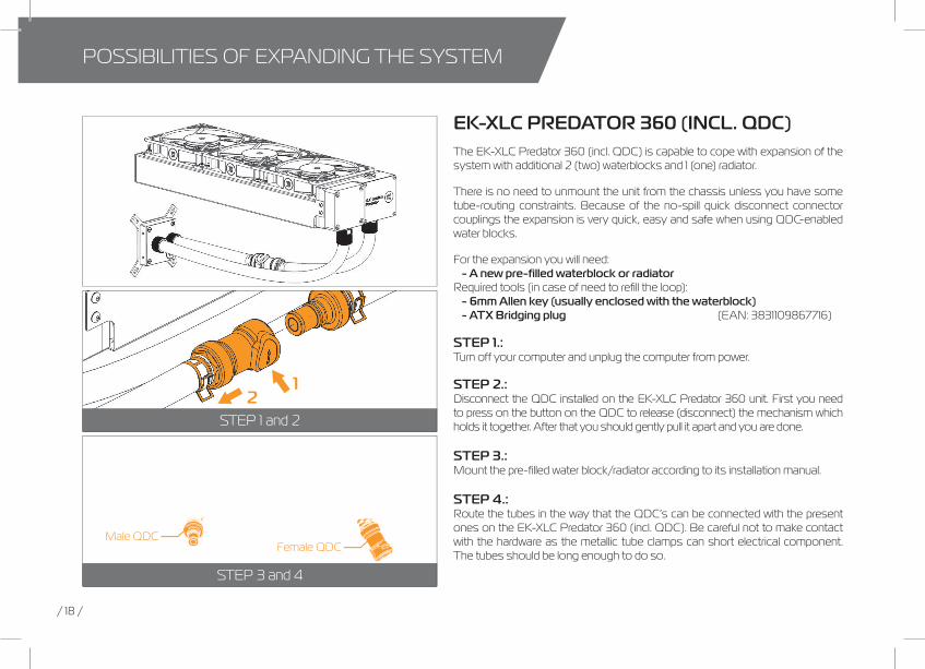
EK-XLC PREDATOR 360 (INCL. QDC)The EK-XLC Predator 360 (incl. QDC) is capable to cope with expansion of the system with additional 2 (two) waterblocks and 1 (one) radiator.
There is no need to unmount the unit from the chassis unless you have some tube-routing constraints. Because of the no-spill quick disconnect connector couplings the expansion is very quick, easy and safe when using QDC-enabled water blocks.
For the expansion you will need:- A new pre-fi lled waterblock or radiator
required tools (in case of need to refi ll the loop):- 6mm Allen key (usually enclosed with the waterblock)- ATX Bridging plug (EAn: 3831109867716)
STEP 1.: Turn off your computer and unplug the computer from power.
STEP 2.: Disconnect the QDC installed on the EK-XLC Predator 360 unit. First you need to press on the button on the QDC to release (disconnect) the mechanism which holds it together. After that you should gently pull it apart and you are done.
STEP 3.: mount the pre-fi lled water block/radiator according to its installation manual.
STEP 4.: route the tubes in the way that the QDC’s can be connected with the present ones on the EK-XLC Predator 360 (incl. QDC). Be careful not to make contact with the hardware as the metallic tube clamps can short electrical component. The tubes should be long enough to do so.
STEP 1 and 2
STEP 3 and 4
21
Female QDCmale QDC

/ 19 /
STEP 5.: Connect the QDC couplings according to the sketch on the right. you will feel the locking click sound when assembled correctly. The installation is now complete.
STEP 6.: Plug in the ATX bridging plug. make sure nothing except the fan splitter hub is plugged to the power supply. you must also unplug the fan and the PWm connectors from the fan splitter hub (Page 7)
STEP 7.: Turn the power supply on and check that only the pump is running.
STEP 8.: It is always a good practice to conduct a 24-hour leak test to ensure the system is leak free and safe to use. Once the test is complete power off the power supply unit and remove the EK-ATX Bridging Plug from the main 24-pin ATX cable.
Upon completing the leak test you can safely reconnect all motherboard-, graphics card- and SATA power cables. your computer is now ready to use.
Before you add the power to your computer please check if everything is installed according to the installation manual.
STEP 9: Starting up your computerTurn on your computer. When turning on the computer check that the tempera-tures of the CPU are normal. It is best practice to enter BIOS/UEFI and check hardware health monitoring section on initial boot!
STEP 5
STEP 6 and 7
STEP 8
OPTIONAL
EK-ATX Bridging Plug
Power supply ATX cable

OPTIONAL
/ 20 /
Adding an external reservoir:
In order to make the refi lling process of the unit after the expansion easier it is recommended to install an additional reservoir.
To achieve the best fl ow balance in the loop it is mandatory to install the reservoir on the last stage in before the water enters the pump/radiator/fans unit – as shown on the picture. you must install your reservoir according to its installation manual. In order to connect it to the existing loop please follow STEP 1 to STEP 9 of the expansion. you should fi ll your reservoir between STEP 5 and STEP 6 in this chapter. It is a good prac-tice to fi ll your loop at the highest point. In our case that means through the reservoir or through the chamber on the pump/radiator/fan unit (see STEP 8. in this chapter)
In our case we have added a reservoir:EK-DBAy Spin reservoir (r3.0) - EAn 3831109840849
InSTALLIng TrAnSPArEnT TUBIng (OPTIOnAL)
When changing the original EK ZmT tubing for transparent tubing (PrimoChill Primo-Flex™ Advanced LrT™ 9,5 mm (3/8”) / 15,9 mm (5/8”) - Crystal Clear tube) or equiv-alent it may happen that the coolant evaporates through the tubing walls due to PVC material being slightly porous.
IMPORTANT: When replacing original EPDm rubber tubing for PVC tubing it is mandatory to check for cooling liquid level on a regular basis. EK highly recom-mends installing additional external reservoirs when replacing the original tubing.
modifying the Predator unit by replacing original soft EPDm tubing with solid tubing (i.e. PETg, Acrylic, copper or similiar) without using any external reser-voir may result in malfunctioning of the unit. Solid tubing does not allow for ex-pansion under thermal load. Under worst case scenario the unit might develop a leak due to increased pressure.

/ 21 /
mAInTEnAnCE
In order to obtain the best performance through whole lifespan of the product it is crucial to follow these maintenance tips:
TIP 1: DUST REMOVALIt is mandatory to remove the dust every 2-3 months. EK recommends to use a vacuum cleaner or compressed air to blow the dust away. The most dusty is usually the radiator so pay special attention to that. Do not forget to turn off the computer and unplug the power supply. It is recommended to remove the dust outside.
TIP 2: CHECKING ELECTRICAL COMPONENTSOnce a year you should check the pump and the fans, if they are running as
they should. The pump and fans must run silently without any rattling noises and must react to PWm duty cycle changes.. All imperfections may lead to overheating and breakdown.
TIP 3: CLEANING THE UNIT (RELATED TO CHAPTER TROUBLESHOOTING)Every 3 years the unit should be thoroughly cleaned. you must let all the coolant out (Page 14). The radiator must be flushed and the pump checked and cleaned. It is recommended to change the tubing.
TIP 4: USE EK DESIGNED AND MANUFACTURED PARTS ONLYIt is recommended to use only genuine EK Water Blocks liquid cooling gear, parts and add-ons to prevent any performance, compatibility and warranty issues.
Q Is Revision 1.1 (R1.1) now fully compatible with all desktop LGA-2011(-3) motherboards? How about older LGA-1366 and -755?
A: yes, due to the use of new mounting mechanism the Predator (r1.1) is now compatible with all standard LgA-2011-3 motherboards, regardless of whether the motherboard has a hole cut-outs on the circuit board.
It is possible to use the Predator (r1.1) on the older LgA-1366 and LgA-775 type motherboards by purchas-ing the optional EK-Supremacy EVO Backplate [EAn: 3830046990648]
Q How many water blocks can you add to the loop?
A: The EK-XLC Predator liquid cooling unit can be upgraded with several ad-ditional parts. However in order to keep performance at a reasonable level it is recommended not to upgrade EK-XLC Predator with no more than:
- one (1) gPU water blocks (Predator 240)- two (2) gPU water blocks (Predator 360)
Additional radiator can also be attached to the loop. For easier filling and bleeding (of air) procedure it is highly recommended for such system to be upgraded with external reservoir as well.
FrEQUEnTLy ASKED QUESTIOnS

/ 22 /
nOTE: To achieve the best performance it is highly recommended to run pump at full speed when expanding the Predator unit with ad-ditional water blocks. Please consult page 27 of this manual.
Q What fl ow rates are to be expected with EK-XLC Predator?
A: The Predator units typically operate at about 135L/h (EK-XLC Preda-tor 360 (incl. QDC)) and 170L/h (EK-XLC Predator 240) respectively.
Installing a typical gPU water block with Quick-Disconnect Couplings (QDC) typically drop fl ow rates from 135L/h to about 105L/h. Adding two would result in fl ow rates of 90L/h. not using Quick-Disconnect Couplings result in fl ow rates of about 125L/h in the same scenario.
Flow rate of 90L/h is considered adequate for successful cooling of the modern high power gPUs.
nOTE: To achieve the best performance it is highly recommended to run pump at full speed when expanding the Predator unit with additional water blocks. Please consult page 19.
Q Is it possible to fl ip the fan orientation?
A: yes, however this requires cutting of the zip-ties holding the cables together. The fans can be removed by the use of enclosed Allen key (2.5mm). When fl ipping the fan orientation it is crucial to keep the zip-ties in place (which function as a washer as well), otherwise the fan screws might pierce and thus irrepairably damage the radiator core.
Q Can the Push-Pull Fan confi guration be used with EK-XLC Predator?
A: yes, the Predator can take accomodate additional fans on the bottom side and thus work in push-pull regime. A set of required screws (m4x6 DIn7984) and Allen key (2.5mm) is enclosed. In order to prevent dam-age to the unit please use the original screws only!
Q Is it possible to ‘daisy-chain’ the integrated PWM splitter?
A: yes, the integrated PWm splitter allows for daisy-chaining of additional PWm splitter cables, such as EK-Cable y-Splitter 2-Fan PWm (10cm) [EAn: 3831109867860], as long as the total power draw does not ex-ceed 25W (2A on +12VDC) - the limit of SATA power connector of the Predator unit.

/ 23 /
IN CASE OF CPU OVERHEATING:Very high CPU temperatures are usually the symptoms of malfunctioning liquid cooling loop, assuming the contact between CPU heat spreader and water block itself is good and that the water itself is adequately cooled within the radiator. This can occur either due to:
1. Malfunctioning or non-working water pump: The symptoms usually include rapid spike in temperature when stressing your CPU to the maxi-mum (for example with Prime95 software). make sure the pump is plugged in to the power connector and that the liquid is indeed flowing in your sys-tem. you should feel the pump vibrating in your hand. Observe the flow indicator or flow meter reading if present. »The gOOD LED indicator on the PWm splitter should glow red when working. no light means no power is getting through – please check electrical connections.
2. Malfunctioning or non-working cooling fans: The symptoms usu-ally include rapid spike in temperature when stressing your CPU to the maximum. make sure the cooling fans are plugged in to the power connec-tor hub and that the blades are indeed rotating. »The gOOD LED indicator on the PWm splitter should glow red when working. no light means no power is getting through – please check electrical connections.
3. Kink in the liquid cooling tubing: Very similar symptoms to both above described. Thin-walled tubing may collapse easily under low radius turns or when obstructed by other computer chassis elements such as closing side panel doors. Check the tubing for any signs of kink which restrict the flow. This is normally not the case when using original tubing.
4. Clogged microchannels in the water block: Clogged microchan-nels in the water block: microchannels can get clogged easily with various dirt particles and impurities, especially with plasticizer powder which has leached from the tubing (When using unsafe liquid cooling tubing). The symptoms usually include rapid spike in temperature when stressing your
CPU to the maximum, flow rates are very low. Visually inspect the water block internals for any buildup or contamination and clean the system if necessary. In case the water block with translucent acrylic top is employed this inspection can be done without disassembling the system.
5. Thermal interface material (paste/grease) not applied or appied improperly: Lack of - or even too much TIm - may result in CPU over-heating. Please refer to STEP 2 in InSTALLIng THE WATEr BLOCK section.
Another culprit could be partially or completely defective CPU. Some CPUs run at higher temperatures than the others. Overheating of the CPU can also occur due to:
1. Poor thermal contact within the CPU itself: Some CPUs, such as Intel LgA-1151 socket based Skylake, Intel LgA-1150 based Haswell and older, socket LgA-1155 based Ivy Bridge are notorious for their poor thermal con-tact between the CPU die and the heat spreader (IHS) itself due to the use of poor TIm. This is the problem of the processor and not the Predator CPU liquid cooling unit. These CPUs are known to run very hot (80°C+) even on factory set frequencies. For best performance it is usually recommended to replace the TIm between the die and the IHS or to even run the proces-sor de-lidded. Both require hazardous IHS removal which voids processor’s warranty but can lead to temperature decrease of 30°C and higher.
Upon exhausting all options please consult EK knowledge base at http://support.ekwb.com . raise a question through EK Support ticketing system if needed.
TrOUBLESHOOTIng

/ 24 /
gEnErAL LIQUID COOLIng PArTS CLEAnIng gUIDE
THE COOLER IS TOO LOUD:The Predator unit is equipped with fast-spinning EK-Vardar high-static pres-sure PWm controlled fans, which run at very high speed if the UEFI/BIOS is not set to control fan speed. make sure to set control mode to PWm (instead of DC)! On majority of motherboards this feature can be found in ‘Hardware monitoring’ section of the UEFI/BIOS. Please consult your motherboard manual on how change fan speed.
General ASUS Z170/X99 motherboard guide:1. Enter UEFI and go to QFAn Control
2. Select the FAn header you wish to edit (the one that you have con-nected the Predator’s PWm cable to)
3. Select PWm mode (instead of DC)
General ASRock Z170/X99 motherboard guide:1. Enter UEFI and go to H/W monitor
2. Choose the FAn header you wish to edit (the one that you have con-nected the Predator’s PWm cable to)
3. Change from ‘Full Speed’ to ‘Silent’, ‘Standard’ or ‘Performance’ mode
General Gigabyte Z170/X99 motherboard guide:1. Enter UEFI and go to m.I.T. - > PC Health Status
2. Select (CPU Fan) Speed Control optionbox and select ‘Auto’, ‘normal’ or ‘manual’.
General MSI Z170/X99 motherboard guide:1. Enter UEFI and go to Hardware monitor
2. Select the FAn header you wish to edit (the one that you have con-nected the Predator’s PWm cable to)
3. Enable Smart Fan mode Checkbox4. Change ramp-up curve by dragging and dropping 4 coloured squares
Liquid cooling parts may be disassembled for cleaning purposes on an occasional basis. your warranty is not voided on disassem-bly of the water block but the customer loses the EK leak-free guar-antee which comes with a factory tested Component. And old, but soft toothbrush is an excellent cleaning tool!
1. Cleaning bare copper: When cleaning bare copper is it recommended to use slightly acidic cleaning agents which include the following organic agents:- (white) vinegar (acetic acid up to 5-10%)- lemon juice (citric acid up to 5-10%)
Certain food can also be used for cleaning copper:- cola (contains phosphorous- and citric acid)- ketchup or tomato extract (contains acetic- and citric acid)- mustard (contains acetic acid)
5% vinegar , dilluted with 95% water is enough to kill 99.9% of algae and bacteria that could be present on copper in an unmaintained cooling loop as well.
Upon cleaning is it necessary to flush the water blocks in water and rinse them
/ 25 /
with distilled water. After rinsing we recommend soaking the water blocks in paper towels until completely dry. It is nearly impossible to avoid the naturally occurring copper tarnishing (oxidation) as the oxidation will reoccur the mo-ment the copper is cleaned of the all oxides.
2. Cleaning nickel plated copper: When cleaning nickel plated copper it is forbidden to use any aggressive chemicals (neither vinegar) or rough materi-als as you may damage the plating and thus void the warranty. Please note also that due to presence of dye additives and other chemicals the nickel layer may also become discolored/stained over time period. However the staining is normally reversible by simple flush and rinse. Cleaning the nickel plated cop-per should consists of these steps:- flush the nickel plated copper under warm water- clean the surface using wet non-abrasive cloth and rinse with clean water- polish the hardened deposits (such as algae or dirt) from the nickel plated
copper if necessary.
EK recommends the use of automotive soft, non-abrasive metal polish cremes. After you finish using other cleaning methods, give the nickel plat-ing a good polish with a non-abrasive metal or chrome polish. Apply a small amount of polish to a cloth or to the surface of the nickel. Wipe the entire surface of the nickel with the polish, using small circular motions, until it looks shiny and clean. Use another clean cloth to remove the remains of the polish-ing paste from the surface. Always rinse with distilled water after you are done with polishing.
3. Cleaning acrylic (plexi) glass tops: Acrylic will fail prematurely if subject-ed to even small amounts of alcohol, acetone or other aggressive chemicals. Please do not use anything but warm, soapy water and a toothbrush to clean the acrylic (plexi) glass water block tops and reservoir tubes. Using aggres-sive chemicals will surely void your warranty!
Algae- or dirt deposits may be rubbed out using soft cloth in com-bination with warm, soapy water. rinse with distilled water after cleaning.
4. Cleaning POM (acetal) tops: POm (polyoxymethylene) or Acetal can withstand chemicals such as alcohol or acetone but EK recommend to use these very sparingly as the drying chemicals will surely leave some residue. Usually the POm can be cleaned easily just be the use of soft cloth and warm, soapy water - without the use of any chemicals. rinse with distilled water after cleaning.
PREVENTIVE STEPS:1. Using corrosion inhibiting coolant (such as EK-Ekoolant or other market proven coolant) is highly recommended for any water cooling loops. Since EK-Ekoolant is also a surfactant is will prevent algae growth and dirt deposition on all wettered surface.
2. Refrain from using Copper Sulphate based additives in your loop in order to prevent tarnishing on your water cooling gear internals!

/ 26 /
PArT SPECIFICATIOn LIST
PUMP XYLEM DDC – 3.1
Pump Xylem DDC - 3.1Pump Type ................................................DC centrifugal PumpBearing Type ............................................Ceramic Bearing Ballrated Voltage ....................................... 12VDCOperating voltage ............................... 8*-13,2VDC *9v startingPump rPm ............................................. 3000rPmDimensions (LxWxH) ..................... 61x60x21Life Expectancy .................................... >50 000hmax head of pump ............................. 1,6m
Operating environmentAmbient temperature ....................... 10-50°CFluid temperature(coolant).......... 10-60°C
FITTINGSFittings Type.................................................................. 2x CompressionType.................................................................. 2x rotary CompressionCompatible tubing (metric) .......... 9,5 mm / 15,9mm (ID/OD Compatible tubing (imperial) ..... 3/8’’ – 5/8’’ (ID/OD)Thread size ................................................g1/4”material .........................................................BrassCoating ..........................................................nickel
DISSASEMBLY OF ROTARY COMPRESSION FITTINGS:In order to disassemble the rotary Compression Fitting sucessfully, namely compression ring from the barb, it is mandatory to use 9 mm Allen key (not enclosed) and lock the barb from the inside. Locking the barb allows for easy unscrewing of the ring.
2,0
3,0
4,0
5,0
6,0
7,0
0,40
0,60
0,80
1,00
1,20
1,40
1,60
1,80
Po
wer
(W)
Hei
ght (
m)
H(Q) P(Q)
rotary compression fi tting
Compression fi tting
0 50 100 150 200 250Volumetric fl ow rate (l/h)

/ 27 /
FAN SPLITTER HUBAll the elements that need electricity to run are connected to the fan splitter hub, located on the bac k of the unit.
This fan splitter hub contains three 4-pin PWm Fan headers for three fans and one pump.
A two-pin header is used to connect Predator unit to mother-board CPU Fan header in order to allow for speed regulation of fans and pump. 2-pin PCI-express miniFIT power header is used to provide power to Predator unit.
General characteristics:- 3x 4-pin PWm fan header (molex KK 254 standard)- 1x 4-pin PWm pump header (molex KK 254 standard)- 1x 2-pin tacho/PWm header (molex KK 254 standard)- 1x 2-pin power header (molex miniFIT standard)- 1x Power LED indicator diode (red)- rectifi ed PWm input- Uniform PWm control on all headers
Connecting the pump directly to motherboard fan header (OPTIONAL)If you want to control the speed of the pump and the fans sepa-rately you should follow the steps below:
STEP 1.: Disconnect the pump’s cable from the fan splitter hub. you will need to remove cable ties in order to do so.
STEP 2.: Connect the pump’s connector to the CPU fan header (prefer-ably) on the motherboard. STEP 1 STEP 2
Pump header
Fan 1/2/3 header
rPm (tacho) and PWm header
Power LED light
Unit main power header
Pump Fan 1Fan 2Fan 3
(Predator 360 only)
To the Power supply unitFan splitter hub

/ 28 /
FANS
EK-Vardar F4-120Fan type ..............................................................PWmrated Voltage ...............................................12 VDCPower Draw ....................................................2,16Wmax Air Flow .................................................. 77 CFm = 131 m³/hStatic Pressure ............................................3.16mm H2O = 31 Panoise Level .....................................................33.5 dBAmax speed .......................................................2200 rpm (+/- 10%)Life Expectancy ..........................................50.000 hrs @ 40°C (mTBF)Dimensions .....................................................120 x 120 x 25 mm
THERMAL GREASE
EK-TIM EctothermType.......................................................................Low ViscosityElectrically conductive ..........................noOptimal working temperature ........+100 to -50(°C)Thermal conductivity.............................8,5 W/mKDensity ...............................................................3 g/cm3
TUBING
EK-Tube ZMT Matte Black 15,9/9,5mmmaterial ..............................................................EPDmColor .....................................................................Black, not UV-reactiveOperating temperature range ........-30°C to 110°CDimensions ....................................................9,5mm/15,9mm (ID/OD)
0
5
10
15
20
25
Pre
ssur
e - P
a
- m3/h 0 20 40 60 80 100 120 140


SUPPOrT AnD SErVICE
For assistance please contact:http://support.ekwb.com/
EKWB d.o.o.Pod lipami 181218 KomendaSlovenia - EU
SOCIAL mEDIA
EKWaterBlocks
@EKWaterBlocks
ekwaterblocks
ekwaterblocks
EKWBofficial