precision thread inserts for plastic parts and equipment ... · precision thread inserts for...
TRANSCRIPT
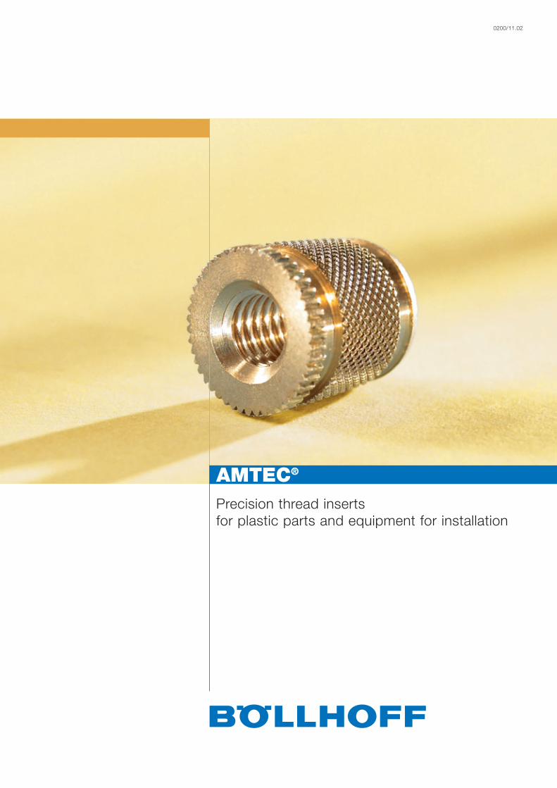
Precision thread insertsfor plastic parts and equipment for installation
0200/11.02
AMTEC®

2
AMTEC® thread inserts
ContentsPage
AMTEC® – highly wear-resistant thread inserts for plastic parts 3The advantages – an overview 3Selection guide for AMTEC® thread inserts 4Selection guide for installation methods 5
Variations
Installation methods – thermal installationThread inserts for thermal installationHITSERT® 2 6 – 7Technical data 9 – 10
Thread inserts for thermal installation, tapping and cold insertionHITSERT® 3 8Technical data 9 – 10
Thread inserts for ultrasonic installationSONICSERT® 11 – 12Technical data 13 – 14
Installation methods 15Installation machines 18 – 18
Installation methods – self-tapping insertionThread inserts for self-tapping insertionQUICKSERT® 19 – 20Technical data 21 – 22
QUICKSERT® Hex 23Technical data 23
QUICKSERT® plus 24Technical data 25 – 26
Installation tools 27 – 29
Installation methods – expansion anchoring Thread inserts for expansion anchoringEXPANSIONSERT 1 and 2 30 – 32Technical data 30 – 32
SPREDSERT® 1 and 2 33 – 34Technical data 35 – 36
SPREDSERT® with retaining flange 37Technical data 37
QUICKSERT® type 1230 38Technical data 38
Installation tools 39 – 40
Fields and examples of application 41 – 42
Product news 43
3
AMTEC® Highly wear-resistant thread inserts for plastic parts
Under the name AMTEC®, Böllhoff offers thread inserts and the corresponding assembly system for aftermouldingtechnology. These thread inserts are especially designed for after-moulding insertion. The result are wear-free,high-strength threads in your high-quality plastic parts.
They are suitable for installation in mouldings of thermoset, thermoplastic or reactive resin materials(also filled or foamed).
There are the following different installation methods:■ Thermal installation – hot plate welding, electromagnetic resistance welding
■ Ultrasonic welding
■ Expansion anchoring
■ Self-tapping insertion
■ Pressing-in
For the most efficient installation method, we offer:■ Manual installation tools
■ Semi-automatic installation tools
■ Automatic machines: Ranging from multiple installation for large-scale production to freely programmableCNC-controlled installation machines for frequently changing components.
Feel free to contact us for customised thread inserts and installation devices. We offer a free CAD downloadservice.Download 3-D models of the AMTEC® products and directly integrate them into your designs(www.boellhoff.com/cad_gb).
The advantages – an overview
■ Reduced injection cycles, automatic injection moulding without insertion of metal parts
■ No risk of damage to the injection mould from falling out metal parts
■ No stress cracks resulting from hardly controllable shrinkage around the metal part
■ Advantages over self-tapping screws since the joint can be detached as often as required without damagingthe thread
■ Safe, tension-free anchorage with high pull-out and torque values
■ Reduction in manufacturing costs for the plastic parts and increased quality of your products
■ Low-maintenance machines in combination with innovative control concepts (service expenditure reducedto a minimum)

4
Selection guide for AMTEC® thread inserts
RequirementsSpecifications
Suitability fordifferent constr.
materials
– Thermoplastics
– Thermosets
– Foams
– Elastomers
Minimuminstallation effort
(machine technology)
Recommendedwall thicknesses
(comparablequality:
1 = low, 4 = high)
Fitting values in equal
thermoplastics
Special requirements:
– Tightness
– Bolt thread
– Through hole
Others
Thiscatalogue,on page
HITSERT® 2
++
– –
– –
– –
Thermal installa-tion machine (min.
quantities withsoldering gun)
1
100 %
with O-ring(implemented)
yes
yes
by taper(8*)
– self-centring
– low-tension
6
HITSERT® 3
++
–
– –
– –
“soldering gun“screwdriver
togglepress
1
100 % for ther malinstallation and
tapping insertion, 70 % for
pressing-in
yes
yes
seal insert,variable
installation
8
QUICKSERT®
plus
++
– –
–
–
ultrasonicweldingmachine
2
110 %
no
no
no
chiplessembedding
19
QUICKSERT®
QUICK-SERT® Hexself-tapping
+
++
0
0
manualinstallation
toolscrewdriver
3
120 %
no
no
no
23
SONICSERT®
++
– –
– –
– –
ultrasonicweldingmachine
2
80 %
with O-ring(possible)
yes
yes
11
QUICKSERT®
type 1230expansion
+
+
–
– –
spindlelifting tool
(possibly press)
4
100 %
_
_
also suitablefor
light metals
24
EXPANSION-SERT 1
0
+
– –
– –
manualinstallationmandrel
4
60 %
no
no
no
easyinstallation
30
EXPANSION-SERT 2
exception
– –
+
+
manualinstallationmandrel
4
–
no
no
no
32
SPREDSERT®
type 1/type 2SPREDSERT®
with retaining flange
type1/withret.flange+
type2/withret.flange+
– –
– –
manualinstallationmandrel
3
50 %
no
no
no
cost-effective
33
Remarks regarding “Fitting values in equal thermoplastics”:Indicated values relate to HITSERT® 2 in PA GF.
– – unsuitable / – limited / 0 satisfactory / + good / ++ very good
!

5
– – unsuitable / – limited / 0 satisfactory / + good / ++ very good
Selection guide for installation methods
To meet the high general requirements to connection technology, fasteners and processing systems must be perfectly designed and matchperfectly. That is why we, as a specialist in fastening and assembly technology, in the field of embedding thread inserts cooperate withKVT Bielefeld GmbH, Werkering 6, 33609 Bielefeld, Germany, phone + 49 (0)521-9320710, [email protected], the welding specialist.
Installation methods Possible Installation Materials Size Batch Installation accuracy Special characteristicssizes time sizes
< 0.05 +/- 0.1 ≥ 0.2
< 50,000 – – ++ ++
≤ M 3 ~ 500,000 – – ++ ++
> 1 Mio. – – ++ ++
< 50,000 – – ++ ++
M 4 – M 6 ~ 500,000 – – ++ ++
> 1 Mio. – – ++ ++
< 50,000 – – + +
≥ M 8 ~ 500,000 – – + +
> 1 Mio. – – + +
< 50,000 ++ ++ ++
≤ M 3 ~ 500,000 ++ ++ ++
> 1 Mio. ++ ++ ++
< 50,000 ++ ++ ++
M 4 – M 6 ~ 500,000 ++ ++ ++
> 1 Mio. ++ ++ ++
< 50,000 ++ ++ ++
≥ M 8 ~ 500,000 ++ ++ ++
> 1 Mio. ++ ++ ++
< 50,000 – – 0 ++
≤ M 3 ~ 500,000 – – 0 ++
> 1 Mio. – – 0 ++
< 50,000 – – 0 ++
M 4 – M 6 ~ 500,000 – – 0 ++
> 1 Mio. – – 0 ++
< 50,000 – – – – – –
≥ M 8 ~ 500,000 – – – – – –
> 1 Mio. – – – – – –
HEW –heat element
weldingM 2 – M 8
approx.3 – 4
seconds(for size
M 4)
thermo-plastics,thermo-plastic
elastomers
thermo-plastics,thermo-plastic
elastomers
thermo-plastics,
– low-tension– multiple installation
possible– well suitable for threaded
bolts– easily convertible to other
thread insert dimensions
– low-tension– multiple installation
possible– especially for inserts
< M 2 as well as insertswith sealing rings
– single-phase or two-phaseprocess can be selected
– high noise emission uponinstallation of metal inserts
– considerable abrasionupon installation of metalinserts
– unsuitable for threadedbolts
– easily convertible to otherthread insert dimensions
approx.3 seconds
(for sizeM 5)
approx.2 seconds
M 1,4 – M 40
M 2 – M 6
ERW –electromagnetic
resistance welding
USW –ultrasonic welding
All dimensions in mm.

6
The advantages■ Ideal for thermoplastic parts
■ Especially designed for thermal installation
■ Screw-locked and low-tension anchoring
■ High pull-out values
■ Efficient installation due to single-spindle, multiple-spindle or automatic machines with preheatingdeviceMaterial: Cu Zn 38 Pb 2 (EU 2000/53 compliant)
Principle
Technical data
The HITSERT® 2 thread insert is heated to the melting temperature of the plastic.As a result of the heat transfer upon insertion, the plastic is plasticised for a shorttime and flows into the undercut of the thread insert. Upon cooling, a low-stressinterference is realised.
Type 0932 Type 0931� Mounting hole�
For installation tools and machines, see pages 16 – 18
Other sizes, special designs and materials on request.
d2
90°
d
I
4°
d3
d2
4°
I
I2
90°
d
D1
I2
D
8°
a
L
Type 0932 Type 0931�
d Order No Order No I l2 d2 d3 D +0.1 D1 Lmin. amin.
M 2 0932 102 0005 0931 102 0056 5.0 0.6 4.1 5.0 3.8 5.2 6.0 1.5M 2.5 0932 125 0005 0931 125 0056 5.0 0.6 4.1 6.0 3.8 6.2 6.0 1.5M 3 0932 103 0005 – 5.0 – 4.7 – 4.4 6.2 6.0 1.8M 3 0932 103 0055 0931 103 0061 5.5 0.6 4.7 6.0 4.4 6.2 6.5 1.8M 3.5 0932 135 0006 0931 135 0068 6.0 0.8 5.5 7.0 5.2 7.2 7.0 1.8M 4 0932 104 0006 – 6.0 – 5.9 – 5.8 8.2 7.0 2.0M 4 0932 104 0075 0931 104 0083 7.5 0.8 5.9 8.0 5.8 8.2 8.5 2.0M 5 0932 105 0007 – 7.0 – 7.0 – 6.9 8.7 8.0 2.0M 5 0932 105 0009 0931 105 0010 9.0 1.0 7.0 8.5 6.9 8.7 10.0 2.5M 6 0932 106 0009 – 9.0 – 8.6 – 8.5 10.2 10.0 2.5M 6 0932 106 0010 0931 106 0011 10.0 1.0 8.6 10.0 8.5 10.2 11.0 2.5M 8 0932 108 0012 0931 108 0013 12.0 1.0 11.1 12.0 10.9 12.2 13.0 3.0
Metric ISO thread according to DIN 13-6H.Technical modifications reserved.All dimensions in mm.
� Guide values: depend on moulding material, may have to be changed after setting trials.� The flange has a large contact surface and thus reduces surface pressure.
Minimum quantity on request.
The versions – thread inserts for thermal installation HITSERT® 2
Inst
alla
tio
n m
etho
d t
herm
al in
stal
lati
on
Inst
alla
tio
n m
etho
d s
elf-
tap
pin
g in
sert
ion
Inst
alla
tio
n m
etho
d e
xpan
sio
n an
cho
ring

7
Technical data
The versions – thread inserts for thermal installation HITSERT® 2
Type 0940 Type 0941� Mounting hole�
For installation tools and machines, see pages 16 – 18
Type 0940� Type 0941�
d Order No Order No I l3 I2 d2 d3� D +0.1� D1 Lmin. amin.
0940 125 0005 0941 125 0005 5.0 5.0 0.6 4.1 6.0 3.8 6.2 6.0 1.5M 2.5 0940 125 0010 0941 125 0010 5.0 10.0 0.6 4.1 6.0 3.8 6.2 6.0 1.5
0940 103 0005 0941 103 0005 5.5 5.0 0.6 4.7 6.0 4.4 6.2 6.5 1.8M 3 0940 103 0010 0941 103 0010 5.5 10.0 0.6 4.7 6.0 4.4 6.2 6.5 1.8
0940 103 0015 0941 103 0015 5.5 15.0 0.6 4.7 6.0 4.4 6.2 6.5 1.80940 135 0005 0941 135 0005 6.0 5.0 0.8 5.5 7.0 5.2 7.2 7.0 1.8
M 3.5 0940 135 0010 0941 135 0010 6.0 10.0 0.8 5.5 7.0 5.2 7.2 7.0 1.80940 135 0015 0941 135 0015 6.0 15.0 0.8 5.5 7.0 5.2 7.2 7.0 1.80940 104 0005 0941 104 0005 7.5 5.0 0.8 5.9 8.0 5.8 8.2 8.5 2.0
M 4 0940 104 0010 0941 104 0010 7.5 10.0 0.8 5.9 8.0 5.8 8.2 8.5 2.00940 104 0015 0941 104 0015 7.5 15.0 0.8 5.9 8.0 5.8 8.2 8.5 2.00940 105 0010 0941 105 0010 9.0 10.0 1.0 7.0 8.5 6.9 8.7 10.0 2.0
M 5 0940 105 0015 0941 105 0015 9.0 15.0 1.0 7.0 8.5 6.9 8.7 10.0 2.00940 105 0025 0941 105 0025 9.0 25.0 1.0 7.0 8.5 6.9 8.7 10.0 2.00940 106 0010 0941 106 0010 10.0 10.0 1.0 8.6 10.0 8.5 10.2 11.0 2.5
M 6 0940 106 0015 0941 106 0015 10.0 15.0 1.0 8.6 10.0 8.5 10.2 11.0 2.50940 106 0025 0941 106 0025 10.0 25.0 1.0 8.6 10.0 8.5 10.2 11.0 2.5
Metric ISO thread according to DIN 13-6g.Technical modifications reserved.All dimensions in mm.
Other lengths, special designs and materials on request.
� Guide values: depend on moulding material, may have to be changed after setting trials.� For blind holes we recommend to provide core pins with ventilation groove.
Feel free to order our company standard.� Minimum quantity on request.� The flange has a large contact surface and thus reduces surface pressure.
d2
I3
C
I
4°
d
d3
d2
I2
I3
C
I
4°
d
D1
I2
8°
D
L
a
➁
Inst
alla
tio
n m
etho
d t
herm
al in
stal
lati
on
Inst
alla
tio
n m
etho
d s
elf-
tap
pin
g in
sert
ion
Inst
alla
tio
n m
etho
d e
xpan
sio
n an
cho
ring

8
HITSERT ® 3 is a tapered universal insert for thermoplastics (thermal installation,tapping and cold insertion).
Owing to its patented external contour (characterised by a fine, self-tapping threadwith asymmetric flank profile) HITSERT ® 3 is the first thread insert to be employedfor the complete range of well established installation methods.
Our Application Engineering Department helps you to find the perfect installationmethod for your application (in terms of installation effort and fitting values). You setthe priorities.
Size Order No d1± l D+0.1* Lmin. amin.
M 3
M 4
M 5
M 6
0935 1030 005
0935 1040 075
0935 1050 009
0935 1060 010
4.7
6.1
7.3
8.9
5
7.5
9
10
4.4
5.8
6.9
8.5
6.0
8.5
10.0
11.0
1.8
2.0
2.0
2.5
* Guide values: depend on moulding material, may have to be changed after setting trials.Minimum quantity on request. German and international patentsAll dimensions in mm. applied for and granted.
The advantages■ Well-proven 8° taper angle
■ Self-centring
■ Large contact surface for plastic prior to installation
■ Flexible installation due to thermal installation,tapping or cold insertion
■ Short installation times
■ Milled external contour (low tolerances)
■ Efficient seal inserts
Principle
Technical data
8°
Da
Lmin
d1
d
4°
I
Type 0935
The versions – thread inserts for thermal installation, tapping and cold insertionHITSERT® 3
Inst
alla
tio
n m
etho
d t
herm
al in
stal
lati
on
Inst
alla
tio
n m
etho
d s
elf-
tap
pin
g in
sert
ion
Inst
alla
tio
n m
etho
d e
xpan
sio
n an
cho
ring

9
Technical data
The versions – thread inserts for thermal installation HITSERT®
0,00
5,00
10,00
15,00
20,00
25,00
30,00
35,00
40,00
45,00
50,00
M 3 M 4 M 5 M 6 M 8
Drehmoment ohne Gegenlager
Drehmoment mit Gegenlager
Torque values HITSERT® M 3 to M 8To
rque
[Nm
]
M 3 M 4 M 5 M 6 M 8■ ABS MA [Nm] 1.20 2.25 2.90 7.00 11.00■ ABS MR [Nm] 3.00 5.50 8.00 17.00 33.00■ PC MA [Nm] 1.60 2.20 4.10 9.50 18.00■ PC MR [Nm] 3.50 6.10 10.50 20.50 48.00■ PA MA [Nm] 1.05 2.40 3.75 5.50 12.00■ PA MR [Nm] 2.50 5.60 9.50 17.50 35.00■ PE/PP MA [Nm] 1.00 2.10 2.50 5.00 9.00■ PE/PP MR [Nm] 2.70 5.00 7.80 15.50 29.00
Torque without thrust bearing (MA[Nm])(jack out)
Torque with thrust bearing (MR[Nm])
Inst
alla
tio
n m
etho
d t
herm
al in
stal
lati
on
Inst
alla
tio
n m
etho
d s
elf-
tap
pin
g in
sert
ion
Inst
alla
tio
n m
etho
d e
xpan
sio
n an
cho
ring
Torque without thrust bearing
Torque with thrust bearing
All dimensions in mm.
10
0
1.000
2.000
3.000
4.000
5.000
6.000
7.000
M 3 M 4 M 5 M 6 M 8
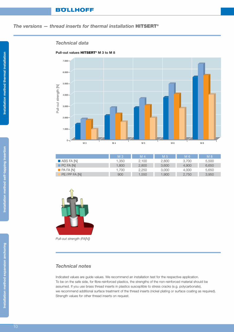
Technical data
The versions — thread inserts for thermal installation HITSERT®
Pull-out values HITSERT® M 3 to M 8P
ull-o
ut s
tren
gth
[N]
M 3 M 4 M 5 M 6 M 8■ ABS FA [N] 1,350 2,100 2,800 3,700 5,500■ PC FA [N] 1,800 2,800 3,600 4,900 6,650■ PA FA [N] 1,700 2,250 3,000 4,000 5,650■ PE/PP FA [N] 900 1,550 1,900 2,750 3,950
Pull-out strength (FA[N])
Technical notes
Indicated values are guide values. We recommend an installation test for the respective application.To be on the safe side, for fibre-reinforced plastics, the strengths of the non-reinforced material should beassumed. If you use brass thread inserts in plastics susceptible to stress cracks (e.g. polycarbonate),we recommend additional surface treatment of the thread inserts (nickel plating or surface coating as required).Strength values for other thread inserts on request.
Inst
alla
tio
n m
etho
d t
herm
al in
stal
lati
on
Inst
alla
tio
n m
etho
d s
elf-
tap
pin
g in
sert
ion
Inst
alla
tio
n m
etho
d e
xpan
sio
n an
cho
ring

11
The versions — thread inserts for ultrasonic installation SONICSERT®
The advantages■ Suitable for thermoplastic parts
■ Especially designed for ultrasonic installation
■ Screw-locked and low-tension anchoring
■ High pull-out values
■ Type 0730 can be installed from both sides.Advantages for automatic feed, since no directionalorientation is required.Material: Cu Zn 38 Pb 2 (EU 2000/53 compliant)
For installation tools and machines, see pages 16 – 18
Type 0730 Type 0733 Type 0734�
d Order No Order No Order No I l2 d2 d3� D+0.1� D1 Lmin. amin.
M1.2� – – 0734 112 0290 2.9 0.4 2.0 2.6 1.6 2.8 3.3 0.65M1.4� 0730 114 0002 – – 2.0 – 2.2 – 1.9 – 2.5 0.70M1.4� – – 0734 114 0310 3.1 0.4 2.2 2.8 1.8 3.2 3.5 0.70M1.6� 0730 116 0250 – – 2.5 – 3.0 – 2.6 – 3.0 0.80M1.6� – – 0734 116 0330 3.3 0.4 2.5 2.9 2.1 3.1 3.7 0.80M2 0730 102 0004 0733 102 0004 0734 102 0046 4.0 0.6 3.6 5.0 3.2 5.2 4.5 2.00M2.5 0730 125 0058 0733 125 0058 0734 125 0064 5.8 0.6 4.6 6.0 4.0 6.2 6.5 2.30M3 0730 103 0058 0733 103 0058 0734 103 0064 5.8 0.6 4.6 6.0 4.0 6.2 6.5 2.30M3.5 0730 135 0072 0733 135 0072 0734 135 0008 7.2 0.8 5.4 7.0 4.8 7.2 8.0 2.50M4 – 0733 104 0072 – 7.2 – 6.3 – 5.6 8.2 8.0 2.50M4 0730 104 0082 0733 104 0082 0734 104 0009 8.2 0.8 6.3 8.0 5.6 8.2 9.0 2.50M5 – 0733 105 0082 – 8.2 – 7.0 – 6.4 8.7 9.0 2.70M5 0730 105 0095 0733 105 0095 0734 105 0105 9.5 1.0 7.0 8.5 6.4 8.7 10.5 2.70M6 – 0733 106 0095 – 9.5 – 8.6 – 8.0 10.2 10.5 3.00M6 0730 106 0127 0733 106 0127 0734 106 0137 12.7 1.0 8.6 10.0 8.0 10.2 14.0 3.00M8 0730 108 0127 0733 108 0127 0734 108 0137 12.7 1.0 10.2 12.0 9.6 12.2 14.0 3.50
Metric ISO thread according to DIN 13-6H.Technical modifications reserved.All dimensions in mm.
Other sizes, special designs and materials on request.
� Guide values: depend on moulding material, may have to be changed after setting trials.� The flange has a large contact surface and thus reduces surface pressure.
Minimum quantity on request.� On request.
Principle The SONICSERT® thread insert is installed with common ultrasonic welders. Uponwelding, the plastic material is plasticised by ultrasonic vibrations and flows into theundercuts of the thread insert. Upon cooling, a low-stress interference is realised.
Type 0730 Type 0733 Type 0734� Mounting hole�
90°d
I
d2
90°d
I
d2
d3
d2
I2
I
90°
d
D1
I2
D
L
a
Technical data
Inst
alla
tio
n m
etho
d t
herm
al in
stal
lati
on
Inst
alla
tio
n m
etho
d s
elf-
tap
pin
g in
sert
ion
Inst
alla
tio
n m
etho
d e
xpan
sio
n an
cho
ring

12
For installation tools and machines, see pages 16 – 18
Type 0743 � Type 0744 �
d Order No Order No I l2/L2 I3 d2 d3� D+0.1� D1 Lmin. amin.
0743 102 0005 0744 102 0005 4.0 0.6 5.0 3.8 5.0 3.2 5.2 4.5 2.0M 2 0743 102 0010 0744 102 0010 4.0 0.6 10.0 3.8 5.0 3.2 5.2 4.5 2.0
0743 125 0005 0744 125 0005 4.0 0.6 5.0 4.6 5.0 3.2 5.2 4.5 2.0M 2.5 0743 125 0010 0744 125 0010 5.8 0.6 10.0 4.6 6.0 4.0 6.2 6.5 2.3
0743 103 0005 0744 103 0005 5.8 0.6 5.0 4.6 6.0 4.0 6.2 6.5 2.3M 3 0743 103 0010 0744 103 0010 5.8 0.6 10.0 4.6 6.0 4.0 6.2 6.5 2.3
0743 103 0015 0744 103 0015 5.8 0.6 15.0 4.6 6.0 4.0 6.2 6.5 2.30743 135 0005 0744 135 0005 7.2 0.8 5.0 5.4 7.0 4.8 7.2 8.0 2.5
M 3.5 0743 135 0010 0744 135 0010 7.2 0.8 10.0 5.4 7.0 4.8 7.2 8.0 2.50743 135 0015 0744 135 0015 7.2 0.8 15.0 5.4 7.0 4.8 7.2 8.0 2.50743 104 0005 0744 104 0005 8.2 0.8 5.0 6.3 8.0 5.6 8.2 9.0 2.5
M 4 0743 104 0010 0744 104 0010 8.2 0.8 10.0 6.3 8.0 5.6 8.2 9.0 2.50743 104 0015 0744 104 0015 8.2 0.8 15.0 6.3 8.0 5.6 8.2 9.0 2.50743 105 0010 0744 105 0010 9.5 1.0 10.0 7.0 8.5 6.4 8.7 10.5 2.7
M 5 0743 105 0015 0744 105 0015 9.5 1.0 15.0 7.0 8.5 6.4 8.7 10.5 2.70743 105 0025 0744 105 0025 9.5 1.0 25.0 7.0 8.5 6.4 8.7 10.5 2.70743 106 0010 0744 106 0010 12.7 1.0 10.0 8.6 10.0 8.0 10.2 14.0 3.0
M 6 0743 106 0015 0744 106 0015 12.7 1.0 15.0 8.6 10.0 8.0 10.2 14.0 3.00743 106 0025 0744 106 0025 12.7 1.0 25.0 8.6 10.0 8.0 10.2 14.0 3.00743 108 0010 0744 108 0010 12.7 1.0 10.0 10.0 12.0 9.6 12.2 14.0 3.5
M 8 0743 108 0015 0744 108 0015 12.7 1.0 15.0 10.0 12.0 9.6 12.2 14.0 3.50743 108 0025 0744 108 0025 12.7 1.0 25.0 10.0 12.0 9.6 12.2 14.0 3.5
Type 0743 Type 0744� Mounting hole�
d2
I3
C
d
d3
d
C
I
I3
I2
d2
D1
L2
Da
L
Metric ISO thread according to DIN 13-6g.Technical modifications reserved.All dimensions in mm.
Other lengths, special designs and materials on request.
� Guide values: depend on moulding material, may have to be changed after setting trials.� Minimum quantity on request.� The flange has a large contact surface and thus reduces surface pressure.
Technical data
The versions – thread inserts for ultrasonic installation SONICSERT®
Inst
alla
tio
n m
etho
d t
herm
al in
stal
lati
on
Inst
alla
tio
n m
etho
d s
elf-
tap
pin
g in
sert
ion
Inst
alla
tio
n m
etho
d e
xpan
sio
n an
cho
ring

13
Technical data
The versions — thread inserts for ultrasonic installation SONICSERT®
0,0
5,0
10,0
15,0
20,0
25,0
30,0
35,0
40,0
45,0
M3 M4 M5 M6 M8
Drehmoment ohne Gegenlager
Drehmoment mit Gegenlager
Torque values SONICSERT® M 3 to M 8To
rque
[Nm
]
M 3 M 4 M 5 M 6 M 8■ ABS MA [Nm] 1.00 1.90 2.50 6.00 9.40■ ABS MR [Nm] 2.60 4.70 6.80 14.50 28.10■ PC MA [Nm] 1.40 1.90 3.50 8.40 15.30■ PC MR [Nm] 3.00 5.20 8.90 17.40 40.80■ PA MA [Nm] 0.90 2.00 3.20 4.70 10.20■ PA MR [Nm] 2.10 4.80 8.10 14.90 29.80■ PE/PP MA [Nm] 0.90 1.80 2.10 4.30 7.70■ PE/PP MR [Nm] 2.30 4.30 6.60 13.20 24.70
Torque without thrust bearing (MA[Nm])(jack out)
Torque with thrust bearing (MR[Nm])
Inst
alla
tio
n m
etho
d t
herm
al in
stal
lati
on
Inst
alla
tio
n m
etho
d s
elf-
tap
pin
g in
sert
ion
Inst
alla
tio
n m
etho
d e
xpan
sio
n an
cho
ring
Torque without thrust bearing
Torque with thrust bearing
All dimensions in mm.

14
0
1.000
2.000
3.000
4.000
5.000
6.000
M 3 M 4 M 5 M 6 M 8
Technical data
The versions — thread inserts for ultrasonic installation SONICSERT®
Pull-out values SONICSERT® M 3 to M 8P
ull-o
ut s
tren
gth
[N]
M 3 M 4 M 5 M 6 M 8■ ABS FA [N] 1,215 1,890 2,520 3,330 4,950■ PC FA [N] 1,620 2,520 3,240 4,410 5,985■ PA FA [N] 1,530 2,025 2,700 3,600 5,085■ PE/PP FA [N] 810 1,395 1,710 2,475 3,555
Pull-out strength (FA[N])
Technical notes
Indicated values are guide values. We recommend an installation test for the respective application.To be on the safe side, for fibre-reinforced plastics, the strengths of the non-reinforced material should beassumed. If you use brass thread inserts in plastics susceptible to stress cracks (e.g. polycarbonate),we recommend additional surface treatment of the thread inserts (nickel plating or surface coating as required).Strength values for other thread inserts on request.
Inst
alla
tio
n m
etho
d t
herm
al in
stal
lati
on
Inst
alla
tio
n m
etho
d s
elf-
tap
pin
g in
sert
ion
Inst
alla
tio
n m
etho
d e
xpan
sio
n an
cho
ring

15
Heat element welding – HEW
Heat element welding is an approved joining process to embed metal thread insertsinto thermoplastic mouldings. It is a single-phase process in which contact heat istransferred through the metal insert to the joining zone of the plastic material.
During fusion of the plastic material in the area of the contact surface, joining iscarried out. In this process, the plasticised mass is displaced into defined recessesand undercuts. That is how a form-closed joint results.
Electromagnetic resistance welding – ERW
ERW is a joining process developed by KVT Bielefeld (Germany) for joints of metaland thermoplastic components. An electromagnetic AC field heats the thread insertwithout contact and the contact surface of the plastic component is plasticised. Inthe simultaneous joining process, the fused material is displaced into recesses andinterlocks.
Heating of metal elements of any size is executed within a very short time(approx. 2 – 6 sec.). After switching off power supply, accelerated cooling of the melttakes place allowing an installation accuracy of up to 0.05 mm.
Ultrasonic welding – USW
USW is a process which had originally been developed for joining thermoplasticcomponents. Within a very short time, the plastic material is plasticised by bound-ary-layer friction and vibration absorption of the parts to be joined.
After that, joining is executed. The energy required is generated as alternating volta-ge in the ultrasonic generator, converted into mechanical vibration (20 – 40 kHz) andthen introduced with a sonotrode.
Upon embedding thread inserts (metallic M 2 – M 6) into thermoplastic components,the fused material is displaced into recesses and undercuts.
Installation method for AMTEC® thread inserts

16
KVT thermal installation machines for AMTEC® thread inserts
KVT 02 lever-type hand-operated thermal installationtool to embed inserts for limited production volumes
Thermal installation machine in special design forsimultaneous embedding of 6 inserts into two car doortrims
KVT Basic 5000 DUO thermal installation machine forsimultaneous thermal installation of four inserts into twocovers of car outside mirrors
KVT Basic 2500 thermal installation machine forsimultaneous thermal installation of two inserts into acar charge air pipe

17
KVT thermal installation machines for AMTEC® thread inserts
ERW thermal installation machine to embed inserts intoparts of a car engine compartment
ERW thermal installation machine to embed four insertsinto a boot handle
ERW thermal installation machine to embed eightinserts M 1.6 into two mobile phone half shells

18
KVT thermal installation machines for AMTEC® thread inserts
Ultrasonic welding machine with a working frequencyof 20 kHz for ultrasonic riveting or welding or to embedUNITEC® K’ in K’ (plastic in plastic) inserts.Allows monitoring of all process parameters and theirtransfer to higher-level systems for production dataacquisition.
Ultrasonic welding machine with a working frequencyof 35 kHz for ultrasonic riveting or welding or to embedUNITEC® K’ in K’ (plastic in plastic) inserts.
Sonotrode for integration into standard and specialsystems
Ultrasonic generator for integration into standard andspecial systems in digital–analogue design

19
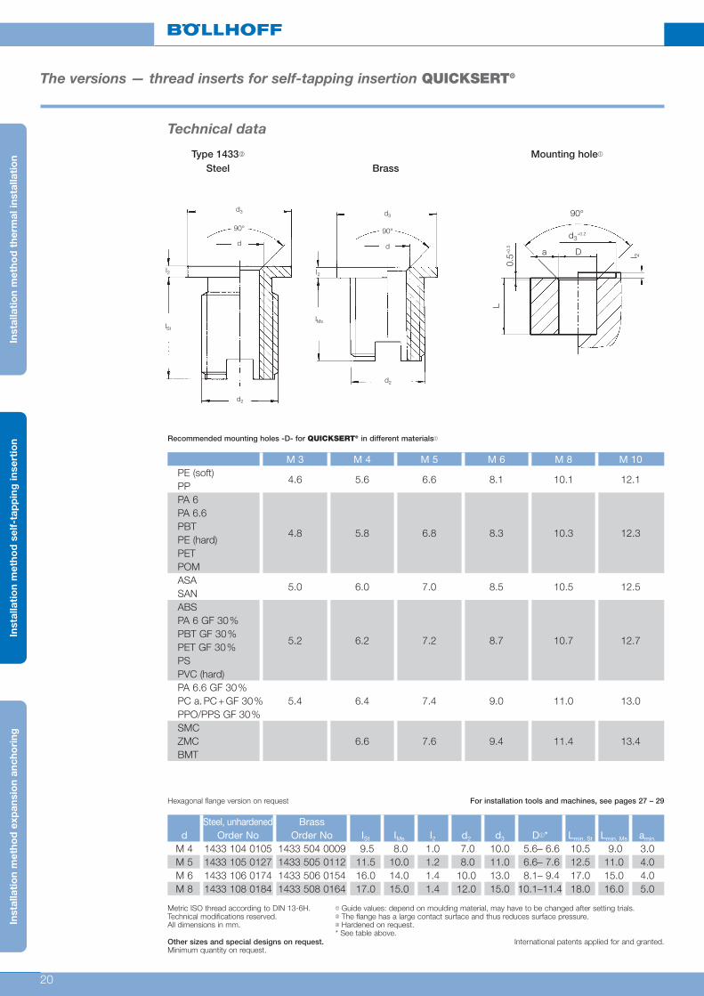
The versions – thread inserts for self-tapping insertion QUICKSERT®
The advantages■ For brittle and ductile plastics such as unsaturated
polyester resins (SMC, ZMC), polyurethane andglass-fibre reinforced thermoplastics
■ Universal use
■ High-strength and torsion-proof threads
■ Optimum assembly characteristics
Material: 1.0718 11 SMnPb 30 zinc coated, chroma-ted or Cu Zn 38 Pb 2 (EU 2000/53 compliant)
Principle QUICKSERT ® consists of a cylindrical basic body withinternal thread and a special external thread. Theprofile of the external thread has an extremely smallflank angle and expands asymmetrically towards thethread root. This way, installation at low driving torquesis optimised.Very good tight-fit is achieved with an ideal distributionof load. The bottom part of the bush is provided with acutting slot. For special requirements, we offer aversion with flange. The threaded bush is screwed inwith a rotating spindle.
Type 1434 Mounting hole�
For installation tools and machines, see pages 27 – 29
Steel, unhardened Brassd Order No Order No I d2 D*� Lmin. amin.
M 3 1434 103 0006 1434 503 0006 6.0 6.0 4.6 –5.4 7.0 2.0M 4 1434 104 0008 1434 504 0008 8.0 7.0 5.6 –6.6 9.0 3.0M 5 1434 105 0010 1434 505 0010 10.0 8.0 6.6 –7.6 11.0 4.0M 6 1434 106 0014 1434 506 0014 14.0 10.0 8.1–9.4 15.0 4.0M 8 1434 108 0015 1434 508 0015 15.0 12.0 10.1–11.4 16.0 5.0M 10� 1434 110 0018 1434 510 0018 18.0 14.0 12.1–13.4 19.0 5.0
Metric ISO thread according to DIN 13-6H.Technical modifications reserved.All dimensions in mm.
Other sizes and special designs on request. International patents applied for and granted.
� Guide values: depend on moulding material, may have to be changed after setting trials.� Minimum quantity on request.* See table on page 20.
Technical data
0.5+
0.5
90°
Da
L
l 2
d3+0.2
Inst
alla
tio
n m
etho
d t
herm
al in
stal
lati
on
Inst
alla
tio
n m
etho
d s
elf-
tap
pin
g in
sert
ion
Inst
alla
tio
n m
etho
d e
xpan
sio
n an
cho
ring
90°
d
I
d2
20
The versions — thread inserts for self-tapping insertion QUICKSERT®
Type 1433� Mounting hole�
Steel Brass
Hexagonal flange version on request For installation tools and machines, see pages 27 – 29
Recommended mounting holes -D- for QUICKSERT® in different materials�
Steel, unhardened Brassd Order No Order No ISt IMs I2 d2 d3 D�* Lmin. St Lmin. Ms amin.
M 4 1433 104 0105 1433 504 0009 9.5 8.0 1.0 7.0 10.0 5.6– 6.6 10.5 9.0 3.0M 5 1433 105 0127 1433 505 0112 11.5 10.0 1.2 8.0 11.0 6.6– 7.6 12.5 11.0 4.0M 6 1433 106 0174 1433 506 0154 16.0 14.0 1.4 10.0 13.0 8.1– 9.4 17.0 15.0 4.0M 8 1433 108 0184 1433 508 0164 17.0 15.0 1.4 12.0 15.0 10.1–11.4 18.0 16.0 5.0
M 3 M 4 M 5 M 6 M 8 M 10PE (soft)
4.6 5.6 6.6 8.1 10.1 12.1PPPA 6PA 6.6PBTPE (hard)
4.8 5.8 6.8 8.3 10.3 12.3
PETPOMASA
5.0 6.0 7.0 8.5 10.5 12.5SANABSPA 6 GF 30%PBT GF 30%
5.2 6.2 7.2 8.7 10.7 12.7PET GF 30%PSPVC (hard)PA 6.6 GF 30%PC a.PC+GF 30% 5.4 6.4 7.4 9.0 11.0 13.0PPO/PPS GF 30%SMCZMC 6.6 7.6 9.4 11.4 13.4BMT
Metric ISO thread according to DIN 13-6H.Technical modifications reserved.All dimensions in mm.
Other sizes and special designs on request. International patents applied for and granted.Minimum quantity on request.
� Guide values: depend on moulding material, may have to be changed after setting trials.� The flange has a large contact surface and thus reduces surface pressure.� Hardened on request.* See table above.
d3
I2
IMs
d2
90°
d
Technical data
0.5+
0.5
90°
Da
L
l 2
d3+0.2
Inst
alla
tio
n m
etho
d t
herm
al in
stal
lati
on
Inst
alla
tio
n m
etho
d s
elf-
tap
pin
g in
sert
ion
Inst
alla
tio
n m
etho
d e
xpan
sio
n an
cho
ring
d3
I2
ISt
d2
90°
d

21
Technical data
The versions – thread inserts for self-tapping insertion QUICKSERT®
0,0
10,0
20,0
30,0
40,0
50,0
60,0
M 3 M 4 M 5 M 6 M 8
Drehmoment ohne Gegenlager
Drehmoment mit Gegenlager
Torque values QUICKSERT® M 3 to M 8To
rque
[Nm
]
M 3 M 4 M 5 M 6 M 8■ ABS MA [Nm] 1.3 2.5 3.2 7.7 12.1■ ABS MR [Nm] 3.3 6.1 8.8 18.7 36.3■ PC MA [Nm] 1.8 2.4 4.5 10.5 19.8■ PC MR [Nm] 3.9 6.7 11.6 22.6 52.8■ PA MA [Nm] 1.2 2.6 4.1 6.1 13.2■ PA MR [Nm] 2.8 6.2 10.5 19.3 38.5■ PE/PP MA [Nm] 1.1 2.3 2.8 5.5 9.9■ PE/PP MR [Nm] 3.0 5.5 8.6 17.1 31.9
Torque without thrust bearing (MA[Nm])(jack out)
Torque with thrust bearing (MR[Nm])
Inst
alla
tio
n m
etho
d t
herm
al in
stal
lati
on
Inst
alla
tio
n m
etho
d s
elf-
tap
pin
g in
sert
ion
Inst
alla
tio
n m
etho
d e
xpan
sio
n an
cho
ring
Torque without thrust bearing
Torque with thrust bearing

22
0
2.000
4.000
6.000
8.000
10.000
12.000
M 3 M 4 M 5 M 6 M 8
Technical data
The versions – thread inserts for self-tapping insertion QUICKSERT®
Pull-out values QUICKSERT® M 3 to M 8P
ull-o
ut s
tren
gth
[N]
M 3 M 4 M 5 M 6 M 8■ ABS FA [N] 2,430 3,780 5,040 6,660 9,900■ PC FA [N] 3,240 5,040 6,480 8,820 11,970■ PA FA [N] 3,060 4,050 5,400 7,200 10,170■ PE/PP FA [N] 1,620 2,790 3,420 4,950 7,110
Pull-out strength (FA[N])
Technical notes
Indicated values are guide values. We recommend an installation test for the respective application.To be on the safe side, for fibre-reinforced plastics, the strengths of the non-reinforced material should beassumed. If you use brass thread inserts in plastics susceptible to stress cracks (e.g. polycarbonate),we recommend additional surface treatment of the thread inserts (nickel plating or surface coating as required).Strength values for other thread inserts on request.
Inst
alla
tio
n m
etho
d t
herm
al in
stal
lati
on
Inst
alla
tio
n m
etho
d s
elf-
tap
pin
g in
sert
ion
Inst
alla
tio
n m
etho
d e
xpan
sio
n an
cho
ring

23
The versions – thread inserts for self-tapping insertion QUICKSERT® Hex
The advantages■ Efficient installation process resulting from additional
driver shape (e.g. hexagonal shape)
■ For thermoplastics and thermosets
■ Extra small flank angles of the special external threadminimise radial tensions
■ High-strength and torsion-proof threads
■ Special version available with external left-handthread for improved reverse locking
Principle QUICKSERT® Hex consists of a cylindrical basic body with internal thread and
additional internal hexagon and a special external thread. The profile of the external
thread has an extremely small flank angle and expands asymmetrically towards the
thread root. This way, installation at low driving torques is optimised. Very good
tight-fit is achieved with an ideal distribution of load. The bottom part of the bush is
provided with a cutting slot. For special requirements, we offer a version with flange.
The threaded bush is inserted and screwed in with a rotating spindle.
It is not necessary to screw out the spindle.
Brass, standard Brass, flanged Order No Order No I l2 d2 d3 Lmin. amin. S
M 4 1437 504 0008 1438 504 0009 8.0 1.0 7.0 10.0 9.0 3.0 3.2M 5 1437 505 0010 1438 505 0112 10.0 1.2 8.0 11.0 11.0 4.0 4.0M 6 1437 506 0014 1438 506 0154 14.0 1.4 10.0 13.0 15.0 4.0 5.0M 8 1437 508 0015 1438 508 0164 15.0 1.4 12.0 15.0 16.0 5.0 6.5
90°
d
d2
l
90°
d
d2
d3
l 2 0.5+
0.5
l
S 90°
Da
L
l 2
d3+0.2
Minimum quantity on request. All dimensions in mm.
For recommended mounting holes -D- for QUICKSERT® Hex in different materials➀ see table on page 20!
Technical data
Inst
alla
tio
n m
etho
d t
herm
al in
stal
lati
on
Inst
alla
tio
n m
etho
d s
elf-
tap
pin
g in
sert
ion
Inst
alla
tio
n m
etho
d e
xpan
sio
n an
cho
ring
Type 1437 Type 1438 Mounting hole

24
The versions – thread inserts for self-forming insertion QUICKSERT® plus
The advantages■ Suitable for thermoplastic parts
■ High-strength and torsion-proof threads
■ Chipless installation
■ Special version available with external left-handthread for improved reverse locking
■ Material: Cu Zn 38 Pb 2 (EU 2000/53 compliant)
Principle QUICKSERT® plus consists of a tapered basic body (8° overall taper) with internal
thread, additional internal hexagon and a special external thread.
The profile of the external thread has an extremely small flank angle and expands
asymmetrically towards the thread root. Driving torques for installation are thus
reduced. Very good tight-fit is achieved with an ideal distribution of load. Since no
cutting slot is required, there is no chip formation because the thread insert forms
into the plastic material.
For special requirements, we offer a version with flange.
The threaded bush is inserted and screwed in with a rotating spindle.
Brassd Order No D+0.1� I d2 Lmin.
� amin.� S
M 4 1430 004 0008 7.10 8.00 7.74 8.00 5.00 3.20M 5 1430 005 0009 8.20 9.00 9.15 9.00 5.50 4.00M 6 1430 006 0011 9.50 11.00 10.70 11.00 6.00 5.00M 8 1430 008 0014 11.90 14.00 13.69 14.00 7.05 6.50
Brass, with flanged Order No D+0.1� I l2 d2 d3 Lmin.
� amin.� S
M 4 1431 004 0104 7.20 10.40 1.4 7.68 10.00 9.00 5.00 3.20M 5 1431 005 0114 8.30 11.40 1.4 9.12 11.50 10.40 5.50 4.00M 6 1431 006 0134 9.60 13.40 1.4 10.67 13.00 12.00 6.00 5.00M 8 1431 008 0174 12.20 17.40 1.4 13.76 18.00 16.00 7.00 6.50
Technical data
� Guide value – depends on moulding material, may have to be changed after setting trials.� For blind hole L + 1 mm.All dimensions in mm.
Inst
alla
tio
n m
etho
d t
herm
al in
stal
lati
on
Inst
alla
tio
n m
etho
d s
elf-
tap
pin
g in
sert
ion
Inst
alla
tio
n m
etho
d e
xpan
sio
n an
cho
ring
Type 1430 Type 1431 Mounting hole

25
Technical data
The versions – thread inserts for self-tapping insertion QUICKSERT® plus
Driving torque values QUICKSERT® plus M 5
Torq
ue [
Nm
]
M 5■ PP ME [Nm] 4.5■ PA 6 GF 30 ME [Nm] 11.4
Inst
alla
tio
n m
etho
d t
herm
al in
stal
lati
on
Inst
alla
tio
n m
etho
d s
elf-
tap
pin
g in
sert
ion
Inst
alla
tio
n m
etho
d e
xpan
sio
n an
cho
ring
M 50
2
4
6
8
10
12

26
Technical data
The versions – thread inserts for self-tapping insertion QUICKSERT® plus
Pull-out values QUICKSERT® plus M 5
Pul
l-o
ut s
tren
gth
[N
]
M 5■ PP FA [N] 3,417■ PA 6 GF FA [N] 10,631
Pull-out strength (FA[N])
Technical notes
Indicated values are guide values. We recommend an installation test for the respective application.To be on the safe side, for fibre-reinforced plastics, the strengths of the non-reinforced material should beassumed. If you use brass thread inserts in plastics susceptible to stress cracks (e.g. polycarbonate),we recommend additional surface treatment of the thread inserts (nickel plating or surface coating as required).Strength values for other thread inserts on request.
Inst
alla
tio
n m
etho
d t
herm
al in
stal
lati
on
Inst
alla
tio
n m
etho
d s
elf-
tap
pin
g in
sert
ion
Inst
alla
tio
n m
etho
d e
xpan
sio
n an
cho
ring
M 50
2000
4000
6000
8000
10000
12000

27
Installation tools – semi-automatic
The versions – thread inserts for self-tapping insertion QUICKSERT®
QUICKSERT® self-tapping insertionAdaptable to box-column drilling machines or cordlessscrewdrivers
■ For small to medium series
QUICKSERT® SemimaticManual installation
Order No Order NoM 3 1450 010 3000 1460 020 3050M 4 1450 010 4000 1460 020 4050M 5 1450 010 5000 1460 020 5050M 6 1450 010 6000 1460 020 6050M 8 1450 010 8000 1460 020 8050
M 10 1450 011 0000 1460 021 0050
QUICKSERT®
Example of a tool application
Inst
alla
tio
n m
etho
d t
herm
al in
stal
lati
on
Inst
alla
tio
n m
etho
d s
elf-
tap
pin
g in
sert
ion
Inst
alla
tio
n m
etho
d e
xpan
sio
n an
cho
ring

28
Installation tools
The versions — thread inserts for self-tapping insertion QUICKSERT®
QUICKSERT® self-tapping insertionPneumatic screwdriver
High performance due to automatic reverse uponreaching the set torque
Stationary operation due to adaptation to parallelguide
Medium to large series
Complete device Exchange unitOrder No Order No
M 3 1460 030 3000 1460 030 3050M 4 1460 030 4000 1460 030 4050M 5 1460 030 5000 1460 030 5050M 6 1460 030 6000 1460 030 6050M 8 1460 030 8000 1460 030 8050M 10 1460 031 0000 1460 031 0050
Matching parallel guide 0182 060 0010
Parallel system type S
Delivery scope:■ 3-axis guiding system ■ Base plate made of extruded ■ Tool holder aluminium profile with grooves,■ 1 balancer 1 – 3 kg dimensions w x h x l: 240 x 40 x 500 mm
Advantages
■ Rationalisation
■ Quick and safe positioning
■ Fatigue-free working
■ No return rotation forces
■ Compensation of screwdriver weight
■ Easy handling
■ Flexibility
■ Can be used with electrical and pneumaticinstallation tools
■ Quick retooling
■ 360° rotatable
■ Smooth and precise roller guides
■ Optimum workstation layout
Type Product characteristics Order No
work radius 140 mm – 600 mmS 600 work height 50 mm – 430 mm 0182 080 0003
weight without tool 8 kgtorque absorption 15 Nm max.
Inst
alla
tio
n m
etho
d t
herm
al in
stal
lati
on
Inst
alla
tio
n m
etho
d s
elf-
tap
pin
g in
sert
ion
Inst
alla
tio
n m
etho
d e
xpan
sio
n an
cho
ring
Type Size Order No
Service at 6 bar unit nominal flow
G 1/4� =700 l/minHose inner diameter 6 0196 000 1130Hose clip 8 – 12 mm 0196 000 1150Hose liner G 1/8�-6 0196 000 1151Hose liner G 1/4�-6 0196 000 1152Exhaust air hose Ø 15 mm 0196 000 1131
29
Installation tools
The versions – thread inserts for self-tapping insertion QUICKSERT® Hex
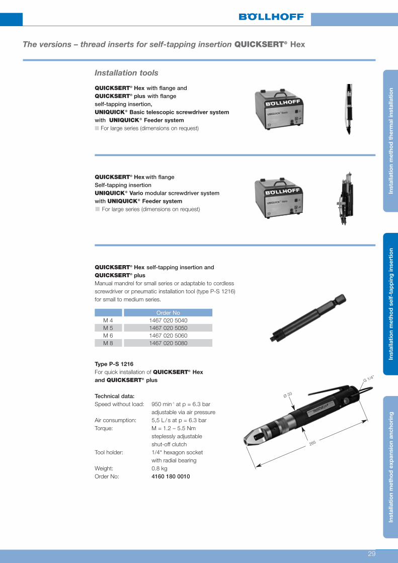
QUICKSERT® Hex with flange andQUICKSERT® plus with flangeself-tapping insertion, UNIQUICK® Basic telescopic screwdriver system with UNIQUICK® Feeder system■ For large series (dimensions on request)
QUICKSERT® Hex self-tapping insertion andQUICKSERT® plusManual mandrel for small series or adaptable to cordlessscrewdriver or pneumatic installation tool (type P-S 1216)for small to medium series.
QUICKSERT® Hex with flangeSelf-tapping insertionUNIQUICK® Vario modular screwdriver systemwith UNIQUICK® Feeder system
For large series (dimensions on request)
Type P-S 1216For quick installation of QUICKSERT® Hexand QUICKSERT® plus
Technical data:Speed without load: 950 min-1 at p = 6.3 bar
adjustable via air pressureAir consumption: 5,5 L / s at p = 6.3 barTorque: M = 1.2 – 5.5 Nm
steplessly adjustableshut-off clutch
Tool holder: 1/4“ hexagon socket with radial bearing
Weight: 0.8 kgOrder No: 4160 180 0010
G 1/4’’
Ø 33
265
Order NoM 4 1467 020 5040M 5 1467 020 5050M 6 1467 020 5060M 8 1467 020 5080
Inst
alla
tio
n m
etho
d t
herm
al in
stal
lati
on
Inst
alla
tio
n m
etho
d s
elf-
tap
pin
g in
sert
ion
Inst
alla
tio
n m
etho
d e
xpan
sio
n an
cho
ring

30
The versions – thread inserts for expansion anchoring Expansionsert 1
The advantages■ Universal thread insert for thermoset and
thermoplastic components
■ High-strength threads by expansion anchoring
■ Quick, cost-effective installation
Material: Cu Zn 38 Pb 2 (EU 2000/53 compliant)
Principle The EXPANSIONSERT1 thread insert consists of across-slotted basic body with internal thread, whichhas an external diamond knurl, and an spreader plate.When the thread insert is installed in the mountinghole, the diamond knurl part is expanded by the spreader plate which is pressed down. As a result, it is anchored in the wall of the hole.
Type 0230 Mounting hole�
EXPANSIONSERT 1 standard
For installation tools and machines, see pages 39 – 40
Metric ISO thread according to DIN 13-6H.Technical modifications reserved.Minimum quantity on request.All dimensions in mm.
Other sizes and special designs on request.
� Guide values: depend on moulding material, may have to be changed after setting trials.
d Order No d1 I I1 min. D+ 0.1� L amin. bmin.
M 2.5 0230 025 0065 4.0 6.5 4.0 4.0 6.5 2.4 3.20230 903 0001 4.0 6.5 4.0 4.0 6.5 2.4 3.2M 30230 003 0065 4.8 6.5 4.0 4.8 6.5 2.9 3.2
M 3.5 0230 035 0008 4.8 8.0 5.0 4.8 8.0 2.9 4.00230 004 0095 5.5 9.5 6.5 5.5 9.5 3.3 4.7
M 40230 004 0008 5.5 8.0 5.0 5.5 8.0 3.3 4.00230 005 0011 6.5 11.0 7.5 6.5 11.0 3.9 5.5
M 50230 005 0008 6.5 8.0 4.5 6.5 8.0 3.9 4.0
M 6 0230 006 0125 8.0 12.5 8.5 8.0 12.5 4.8 6.2M 8 0230 008 0016 11.0 16.0 11.0 11.0 16.0 6.6 8.0
d1
90°d
II1
D
L
b
a
Inst
alla
tio
n m
etho
d t
herm
al in
stal
lati
on
Inst
alla
tio
n m
etho
d s
elf-
tap
pin
g in
sert
ion
Inst
alla
tio
n m
etho
d e
xpan
sio
n an
cho
ring
Technical data

31
The versions – thread inserts for expansion anchoring Expansionsert 1
Technical data
Type 0231� Mounting hole�
EXPANSIONSERT 1 flange
Type 0232 Mounting hole�
EXPANSIONSERT 1 clinch (same dimensions as type 0231)
Metric ISO thread according to DIN 13-6H.Technical modifications reserved.Minimum quantity on request.All dimensions in mm.
Other sizes and special designs on request.
� Guide values: depend on moulding material, may have to be changed after setting trials.
d Order No I d1 d2 d 3 max. d4 D +0.1� D1+0.2 I1 min. I 2 I 3
M 2.5 0232 025 0007 7.0 4.0 5.5 3.6 2.8 4.0 5.5 3.6 0.8 1.0M 3 0232 003 0007 7.0 4.8 6.3 4.1 3.3 4.8 6.3 3.5 0.8 1.0M 3.5 0232 035 0085 8.5 4.8 6.3 4.6 3.8 4.8 6.3 4.7 0.8 1.0M 4 0232 004 0085 8.5 5.5 7.0 5.1 4.3 5.5 7.0 4.4 0.8 1.0M 5 0232 005 0095 9.5 6.5 8.0 6.1 5.3 6.5 8.0 5.0 0.8 1.0M 6 0232 006 0012 12.0 8.0 10.0 7.1 6.3 8.0 10.0 7.0 0.8 1.0
Metric ISO thread according to DIN 13-6H.Delivery conditions according to DIN 267.Technical modifications reserved.Minimum quantity on request.
� Guide values: depend on moulding material, may have to be changed after setting trials.The flange has a large contact surface and thus reduces surface pressure.
d Order No I d1 d2 I1 min. I2 D +0.1� D1+0.2 L L1 amin. bmin.
M 2.5 0231 025 0006 6.0 4.0 5.5 3.6 0.8 4.0 5.5 5.2 6.0 2.4 3.2M 3 0231 003 0006 6.0 4.8 6.3 3.5 0.8 4.8 6.3 5.2 6.0 2.9 3.2M 3.5 0231 035 0075 7.5 4.8 6.3 4.7 0.8 4.8 6.3 6.7 7.5 2.9 4.0M 4 0231 004 0075 7.5 5.5 7.0 4.4 0.8 5.5 7.0 6.7 7.5 3.3 4.7M 5 0231 005 0085 8.5 6.5 8.0 5.0 0.8 6.5 8.0 7.7 8.5 3.9 5.5M 6 0231 006 0011 11.0 8.0 10.0 7.0 0.8 8.0 10.0 10.2 11.0 4.8 6.2
d2
I2
d1
I1I
90°d
D1
D
I2
L1
b
a
L
d2
d1
I3
I2
I1 I
d3
d4
dD1
I2
L1
b
Da
L
The clinched edge is designed tofasten contact components andcable eyes as well as to serve as afixing aid for a cover part to beapplied.
For installation tools, see pages 39 – 40
For installation tools, see pages 39 – 40
Other sizes and special designs on request.
Inst
alla
tio
n m
etho
d t
herm
al in
stal
lati
on
Inst
alla
tio
n m
etho
d s
elf-
tap
pin
g in
sert
ion
Inst
alla
tio
n m
etho
d e
xpan
sio
n an
cho
ring

32
The advantages■ For reactive resins, PUR, elastomers, integral hard
foams as well as for wood composite materials
■ Wear-resistant threads
■ Quick, cost-effective installation
Material: Cu Zn 38 Pb 2 (EU 2000/53 compliant)
Principle
Technical data
The EXPANSIONSERT 2 thread insert consists of abody with internal thread, which has knurls and under-cuts on the circumferential surface. Inside the body,there is an spreader plate that is pressed downwardswhen the thread insert is installed in the mounting hole.Upon installation, the slotted bottom part of theEXPANSIONSERT 2 is expanded and its cuttingrings are anchored in the wall of the mounting hole.The thread insert is thus reliably secured against pull-out and twisting.
Type 0235 Mounting hole�
For installation tools and machines, see pages 39 – 40
Metric ISO thread according to DIN 13-6H.Technical modifications reserved.Minimum quantity on request.All dimensions in mm.
Other sizes and special designs on request.
� Guide values: depend on moulding material, may have to be changed after setting trials.
d Order No I d2 d3 I1 I2 D+ 0.1� D1 L min. a min.
M 3 0235 103 0008 8.0 5.9 7.0 3.0 0.8 5.5 7.2 8.2 4.0M 3.5 0235 135 0008 8.0 5.9 7.0 3.5 0.8 5.5 7.2 8.2 4.0M 4 0235 104 0095 9.5 6.9 8.0 4.0 0.8 6.5 8.2 9.8 5.0M 5 0235 105 0011 11.0 8.4 10.0 5.0 0.8 8.0 10.2 11.3 6.0M 6 0235 106 0125 12.5 8.4 10.0 6.0 0.8 8.0 10.2 12.8 6.0
d3
d2
I2
I1
90°
d
I
D1
I2
D
L
a
The versions – thread inserts for expansion anchoring Expansionsert 2
Inst
alla
tio
n m
etho
d t
herm
al in
stal
lati
on
Inst
alla
tio
n m
etho
d s
elf-
tap
pin
g in
sert
ion
Inst
alla
tio
n m
etho
d e
xpan
sio
n an
cho
ring

33
The versions – thread inserts for expansion anchoring SPREDSERT® 1
The advantages■ For thermoplastic parts
■ Knurled flange and anchor rings ensure high degreeof security against twisting and tensile load
■ Screw locking
Material: Cu Zn 38 Pb 2 (EU 2000/53 compliant)
Principle The SPREDSERT® 1 is inserted into the mountinghole until the retaining flange is completely anchored inthe plastic material. In that process, the slotted area iscompressed. The radially secured SPREDSERT® 1 isexpanded by the screw so that the anchor rings pene-trate the plastic material and ensure the tight-fit of thethread insert. In this process, the screw is locked. Forthe additional expansion force, the tightening torquemust be increased by 10 %.
Type 0831 – 0833 Mounting hole�
For installation tools and machines, see pages 39 – 40
Metric ISO thread according to DIN 13-6H.Technical modifications reserved.Minimum quantity on request.All dimensions in mm.
Other sizes and special designs on request.
� Guide values: depend on moulding material, may have to be changed after setting trials.� Screw contact length = min. insert length (l) + 1p (pitch)
Number ofd Order No anchor rings d1 d2 d3 I � I1 D+ 0.1� L min. a min.
M 2 0832 102 0004 3 3.15 3.7 3.6 4.0 0.6 3.2 4.5 2.0M 2.5 0832 125 0005 3 3.9 4.5 4.4 5.0 0.75 4.0 5.5 2.5M 3 0832 103 0005 3 3.9 4.5 4.4 5.0 0.75 4.0 5.5 3.0M 3.5 0832 135 0065 3 4.7 5.3 5.2 6.5 1.0 4.8 7.1 3.2M 4 0833 104 0008 4 5.35 6.0 5.9 8.0 1.3 5.5 8.7 3.5M 5 0833 105 0095 5 6.35 7.0 6.9 9.5 1.3 6.5 10.3 4.0M 6 0831 106 0011 5 7.85 8.5 8.4 11.0 2.0 8.0 12.0 5.0M 8 0831 108 0013 5 9.5 9.95 9.9 13.0 2.0 9.6 14.0 7.0
d2
I1
I
d1
d3
90°
dD
L
a
Technical data
Inst
alla
tio
n m
etho
d t
herm
al in
stal
lati
on
Inst
alla
tio
n m
etho
d s
elf-
tap
pin
g in
sert
ion
Inst
alla
tio
n m
etho
d e
xpan
sio
n an
cho
ring

34
The advantages■ For thermoset parts
■ Knurled flange and diamond knurl ensure highdegree of security against twisting and tensile load
■ Screw locking
Material: Cu Zn 38 Pb 2 (EU 2000/53 compliant)
Principle The SPREDSERT® 2 is inserted into the mountinghole until the retaining flange is completely anchored inthe plastic material. In that process, the slotted area iscompressed. The radially secured SPREDSERT® 2 isexpanded by the screw so that the diamond knurlingpenetrates the plastic material and ensures the tight-fitof the thread insert. In this process, the screw islocked.For the additional expansion force, the tighteningtorque must be increased by 10 %.
Type 0837 Mounting hole�
For installation tools and machines, see pages 39 – 40
d Order No� I � d2 D+ 0.1� L min. a min.
M 3.5 0837 103 0005 5.0 4.3 3.9 5.5 3.0M 3.5 0837 135 0064 6.4 5.1 4.7 7.0 3.3M 4.5 0837 104 0008 8.0 6.0 5.5 8.5 3.5M 5.5 0837 105 0095 9.5 6.8 6.3 10.0 4.0M 6.5 0837 106 0127 12.7 8.4 7.9 13.5 5.0
Metric ISO thread according to DIN 13-6H.Technical modifications reserved.All dimensions in mm.Other sizes and special designs on request.
� Guide values: depend on moulding material, may have to be changed after setting trials.� Minimum quantity on request.� Screw contact length = min. insert length (l) + 1p (pitch)
90°
d
I
d2
Da
L
The versions – thread inserts for expansion anchoring SPREDSERT® 2
Technical data
Inst
alla
tio
n m
etho
d t
herm
al in
stal
lati
on
Inst
alla
tio
n m
etho
d s
elf-
tap
pin
g in
sert
ion
Inst
alla
tio
n m
etho
d e
xpan
sio
n an
cho
ring

35
Technical data
The versions – thread inserts for expansion anchoring SPREDSERT® 1 + 2
0,00
5,00
10,00
15,00
20,00
25,00
30,00
M 3 M 4 M 5 M 6 M 8
Drehmoment ohne Gegenlager
Drehmoment mit Gegenlager
Torque values SPREDSERT® 1 + 2 / M 3 to M 8To
rque
[Nm
]
M 3 M 4 M 5 M 6 M 8■ ABS MA [Nm] 0.72 1.35 1.74 4.20 6.60■ ABS MR [Nm] 1.80 3.30 4.80 10.20 19.80■ PC MA [Nm] 0.96 1.32 2.46 5.70 10.80■ PC MR [Nm] 2.10 3.66 6.30 12.30 28.80■ PA MA [Nm] 0.63 1.44 2.25 3.30 7.20■ PA MR [Nm] 1.50 3.36 5.70 10.50 21.00■ PE/PP MA [Nm] 0.60 1.26 1.50 3.00 5.40■ PE/PP MR [Nm] 1.62 3.00 4.68 9.30 17.40
Torque without thrust bearing (MA[Nm])(jack out)
Torque with thrust bearing (MR[Nm])
Inst
alla
tio
n m
etho
d t
herm
al in
stal
lati
on
Inst
alla
tio
n m
etho
d s
elf-
tap
pin
g in
sert
ion
Inst
alla
tio
n m
etho
d e
xpan
sio
n an
cho
ring
Torque without thrust bearing
Torque with thrust bearing

36
0
500
1.000
1.500
2.000
2.500
3.000
3.500
4.000
M 3 M 4 M 5 M 6 M 8
Technical data
The versions – thread inserts for expansion anchoring SPREDSERT® 1 + 2
Pull-out values SPREDSERT® 1 + 2 / M 3 to M 8P
ull-o
ut s
tren
gth
[N]
M 3 M 4 M 5 M 6 M 8■ ABS FA [N] 810 1,260 1,680 2,220 3,300■ PC FA [N] 1,080 1,680 2,160 2,940 3,990■ PA FA [N] 1,020 1,350 1,800 2,400 3,390■ PE/PP FA [N] 540 930 1,140 1,650 2,370
Pull-out strength (FA[N])
Technical notes
Indicated values are guide values. We recommend an installation test for the respective application.To be on the safe side, for fibre-reinforced plastics, the strengths of the non-reinforced material should beassumed. If you use brass thread inserts in plastics susceptible to stress cracks (e.g. polycarbonate),we recommend additional surface treatment of the thread inserts (nickel plating or surface coating as required).Strength values for other thread inserts on request.
Inst
alla
tio
n m
etho
d t
herm
al in
stal
lati
on
Inst
alla
tio
n m
etho
d s
elf-
tap
pin
g in
sert
ion
Inst
alla
tio
n m
etho
d e
xpan
sio
n an
cho
ring

37
The versions – thread inserts for expansion anchoring SPREDSERT® with retaining flange
The advantages■ For thermoset and thermoplastic components
■ High-strength threads in through holes
■ Screw locking
Material: Cu Zn 38 Pb 2 (EU 2000/53 compliant)
Principle The SPREDSERT® with retaining flange is insertedinto the through hole until the retaining flange is seated.The slotted anchoring section with diamond knurl iscompressed.By screwing in the screw, the thread insert is forcedopen in the anchoring section so that the diamondknurling penetrates the plastic material. The retainingflange which acts as a shoulder support ensures highpull-out locking while the screw is also locked. For theadditional expansion force, the tightening torque mustbe increased by 10 %.
Type 0835 Mounting hole�
For installation tools and machines, see pages 39 – 40
Metric ISO thread according to DIN 13-6H.Technical modifications reserved.Minimum quantity on request.All dimensions in mm.
Other sizes and special designs on request.
� Guide values: depend on moulding material, may have to be changed after setting trials.� Screw contact length = min. insert length (l) + 1p (pitch)
d Order No I � d2 d3 I2 D+ 0.1� L min. a min.
M 3 0835 103 0048 4.8 4.3 5.5 0.5 3.9 4.5 3.2M 3.5 0835 135 0064 6.4 5.1 6.3 0.7 4.7 6.0 3.6M 4 0835 104 0008 8.0 6.0 7.0 0.8 5.5 7.5 4.0M 5 0835 105 0095 9.5 6.8 8.0 1.0 6.3 9.0 4.8M 6 0835 106 0127 12.7 8.4 9.5 1.3 7.9 12.0 6.0M 8 0835 108 0127 12.7 9.9 11.0 1.3 9.4 12.0 7.1
d2
d3
I2
90°
d
I
D
L
a
Technical data
Inst
alla
tio
n m
etho
d t
herm
al in
stal
lati
on
Inst
alla
tio
n m
etho
d s
elf-
tap
pin
g in
sert
ion
Inst
alla
tio
n m
etho
d e
xpan
sio
n an
cho
ring

38
For installation tools and machines, see pages 39 – 40
TotalTotal length Knurls
Steel Brass length installed ød Order No Order No l l1 d2 D+0.1� Lmin L2min a
M3 1230 003 0048 1230 103 0048 8.0 4.8 5.5 5.5 8.8 4.8 2M4 1230 004 0063 1230 104 0063 10.5 6.3 6.5 6.5 11.8 6.3 2M5 1230 005 0082 1230 105 0082 13.5 8.2 7.5 7.5 15.2 8.2 2.5M6 1230 006 0098 1230 106 0098 16.0 9.8 9 9 18.8 9.8 3M8 1230 008 0 115 1230 108 0 115 19.0 11.5 12 12 21.0 11.5 4
Mounting hole
Minimum quantity on request. All dimensions in mm.
For installation into plastic, we recommend brass thread inserts. Special lengths and thread diameters as well as other materials on request.� Guide values: depend on moulding material, may have to be changed after setting trials.* * Particularly test this insert for suitability for plastics susceptible to stress cracks (e.g. PC, PPO).
The advantages■ No tapping
■ Quick, cost-effective installation
■ Chipping-free installation in smooth mounting holes
■ High-strength threads in light metals
■ High-strength threads in thermoplastic and thermosetcomponents* * after moulding of components
■ Suitable for one-sided accessibility of the installation point
■ For screwed connections that can be detached asoften as required
■ For installation on finished surfaces
Material: 11 SMn Pb 30+c
Surface: A2J ISO 4042 Cr (VI)-freeor Cu Zn 38 Pb 2 (EU 2000/53 compliant)
Principle The QUICKSERT® Expansion is spun on to the rotating threaded mandrel of theinstallation tool and introduced into the mounting hole. The hole can be preformedor machined with common drills as a blind or through hole. The axial pulling motionof the threaded mandrel causes the QUICKSERT® Expansion Expansion to shearat the predetermined breaking point between anchoring sleeve and threaded bush.The threaded bush is pulled into the anchoring sleeve and expands it.Meanwhile, the diamond knurl of the anchoring sleeve is pressed into thewall of the hole. The thread insert is now anchored and locked against screwing andpull-out.
Type 1230 Mounting hole�
d2
I
d
D
L
L2
a
The versions – thread inserts for expansion anchoring QUICKSERT® Expansion type 1230
Technical data
Inst
alla
tio
n m
etho
d t
herm
al in
stal
lati
on
Inst
alla
tio
n m
etho
d s
elf-
tap
pin
g in
sert
ion
Inst
alla
tio
n m
etho
d e
xpan
sio
n an
cho
ring

39
Installation tools – manual installation tools
The versions — thread inserts for expansion anchoring
EXPANSIONSERT 1, EXPANSIONSERT 2, SPREDSERT® 1 and 2Assembly mandrels for manual installation of EXPANSIONSERT 1, EXPANSIONSERT 2 thread inserts
EXPANSIONSERT1 EXPANSIONSERT1 EXPANSIONSERT2 SPREDSERT®
Standard Flange/ClinchOrder No Order No Order No Order No
M 2.5 0250 025 0065 0253 025 0006 – 0851 125 0000M 3 0250 003 0065 0253 003 0006 0254 103 0008 0851 103 0000M 3.5 0250 035 0008 0253 035 0075 – 0851 135 0000
0250 004 0095 0253 004 0075 0254 104 0095 0851 104 0000M 40250 004 0008 0253 004 0075 0254 104 0095 0851 104 00000250 005 0011 0253 005 0085 0254 105 0011 0851 105 0000M 50250 005 0008 0253 005 0085 0254 105 0011 0851 105 0000
M 6 0250 006 0125 0253 006 0011 0254 106 0125 0851 106 0000M 8 0250 008 0016 – – 0851 108 0000
Semi-automatic toolsEXPANSIONSERT 1, EXPANSIONSERT 2The tool can be integrated into manual lever presses orother pressing devices.
■ For small to medium series
EXPANSIONSERT1 EXPANSIONSERT1 EXPANSIONSERT2 SemimaticStandard Flange/ClinchOrder No Order No Order No Order No
M 2.5 – 0263 025 0006 – –M 3 0260 003 0065 0263 003 0006 0264 103 0008 1460 020 3050M 3.5 0260 035 5008 0263 035 0075 0264 103 5008 –
M 40260 004 0095 0263 004 0075 0264 104 0095 1460 020 40500260 004 0008 0263 004 0075 0264 104 0095 1460 020 4050
M 50260 005 0011 0263 005 0085 0264 105 0011 1460 020 50500260 005 0008 0263 005 0085 0264 105 0011 1460 020 5050
M 6 0260 006 0125 0263 006 0011 0264 106 0125 1460 020 6050M 8 – – – 1460 020 8050M 10 – – – 1460 021 0050
EXPANSIONSERT1,EXPANSIONSERT 2Example of a tool application
Inst
alla
tio
n m
etho
d t
herm
al in
stal
lati
on
Inst
alla
tio
n m
etho
d s
elf-
tap
pin
g in
sert
ion
Inst
alla
tio
n m
etho
d e
xpan
sio
n an
cho
ring

40
Installation tools – QUICKSERT® ExpansionMachine installation tools with hydraulic–pneumatic drive
The versions – thread inserts for expansion anchoring QUICKSERT® Expansion
Setting tool P 2005 allows quick and safe installation.
■ For medium to large series
Price: 1,200,– €Order No 2361 550 6000
xx = metric dimension,Example: M6 = 06 for QUICKSERT® M6.
Designation Order No
Threaded mandrel 2361 13x x020Nosepiece 2361 13x x030
Inst
alla
tio
n m
etho
d t
herm
al in
stal
lati
on
Inst
alla
tio
n m
etho
d s
elf-
tap
pin
g in
sert
ion
Inst
alla
tio
n m
etho
d e
xpan
sio
n an
cho
ring

41
Fields of application
AMTEC® thread insertsare used in most diversefields:
■ Motor vehicles andmotorcycles, air bagsetc.
■ Commercial vehicles
■ Interior
■ Electrics, electronics,safes
■ Air-conditioning tech-nology and systemsetc.
■ Office furniture,desks, photocopyingmachines

42
AMTEC® examples of application ...
Pump casings, HITSERT® 2 M 5 andSPREDSERT® with retaining flange M 6
Pump casings, HITSERT® 2 bolts M 6 andcompression limiters
QUICKSERT® Expansion Expansion insert with collar / steel
EXPANSIONSERT 1with hexagon flange /brass
HITSERT® 3Seal insert hose coupling/brass
Customer-specific special part, silvered HITSERT® hose coupling with temperature-resistantO-ring
HITSERT® seal thread insert SONICSERT® compression limiter with captive screw
... and customer-specific solutions
43
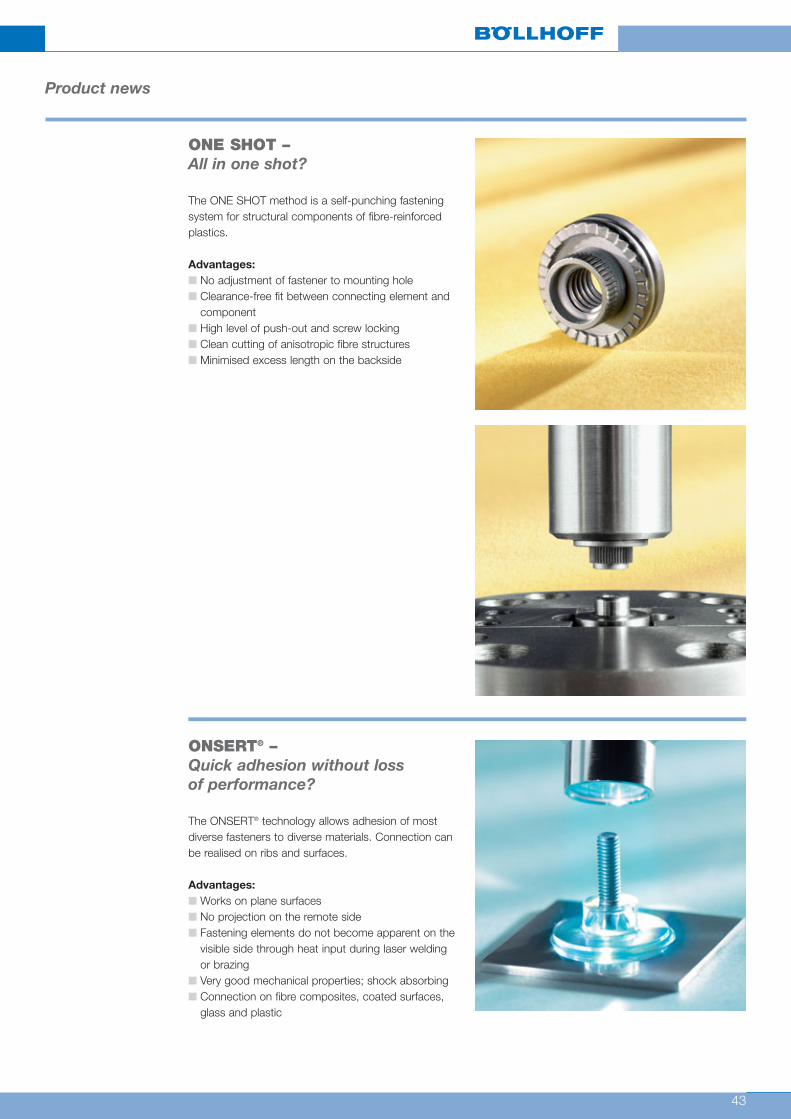
ONE SHOT –All in one shot?
The ONE SHOT method is a self-punching fasteningsystem for structural components of fibre-reinforcedplastics.
Advantages:■ No adjustment of fastener to mounting hole■ Clearance-free fit between connecting element and
component ■ High level of push-out and screw locking ■ Clean cutting of anisotropic fibre structures ■ Minimised excess length on the backside
Product news
ONSERT® –Quick adhesion without lossof performance?
The ONSERT® technology allows adhesion of mostdiverse fasteners to diverse materials. Connection canbe realised on ribs and surfaces.
Advantages:■ Works on plane surfaces■ No projection on the remote side■ Fastening elements do not become apparent on the
visible side through heat input during laser weldingor brazing
■ Very good mechanical properties; shock absorbing■ Connection on fibre composites, coated surfaces,
glass and plastic

Subject to technical change.Reprinting, even in extract form, only permitted with express consent.Observe protective note according to DIN 34.
Böllhoff International with companies in:
Argentina
Austria
Brazil
Canada
China
Czech Republic
France
Germany
Hungary
India
Italy
Japan
Mexico
Poland
Romania
Russia
Slovakia
Spain
Turkey
United Kingdom
USA
Apart from these 21 countries, Böllhoff supports its international customers in other important industrial markets in close partnership
with agents and dealers.
Böllhoff GroupPlease find your local contact on www.boellhoff.com
or contact us under [email protected]