precision torque control in an easy-to-use ac...
TRANSCRIPT

Precision TorqueControlin anEasy-To-UseAC Drive.
1336 IMPACT ™ AC DRIVE
™

2
1336 IMPACT AC Drive
Stand-aloneTorque Control
Product Highlights• Force Technology™ for
demanding speed and torque performance
• Patented current regulatorprovides true control of motor torque
• Simple Start-Up featureprovides for fastcommissioning and quickauto-tuning of speed andtorque loops using motornameplate data
• 16-step speed profilingfeature for changing speedbased on time, encodercounts or hardware inputsthrough the L-option card
• Encoderless Field-OrientedControl
• SCANport™ protocol provides common interfacefor programming devices
• Internal Process Trim Controller
• Common power platform of 1336 PLUS II and 1336FORCE™ family of drives
Flexible, Yet UncomplicatedThe 1336 IMPACT drive isdesigned for simple set-up andoperation but still provides thefeatures of more complicateddrives. The Quick Motor Tuneprocedure steps the operatorthrough menus to load simplemotor data, while the otherrequired parameters areautomatically loaded. Thiseliminates the need forcomplex motor parameterinformation. The configurableanalog, digital I/O and variouscommunication modules allowyou to make your preferredcommunication choice.
High Performance Speed and Torque Control The 1336 IMPACT AC drive with Force Technology provides the precise motor speed and torque controlnecessary to handle some of the most demanding drive applications, including many that are typicallyreserved for DC drives. Force Technology, an Allen-Bradley patented Field-Oriented Control method, hasa proven and unique ability to separate and independently control motor flux and torque allowing the1336 IMPACT drive to deliver full torque down to zero speed. Force Technology, originally designed forcustomized drive systems, is now available in a compact, easy-to-use, stand-alone package.
Using the optional encoder interface, speed regulation is +/- 0.001% of top speed over a 100:1 speedrange with an operating speed range of 1000:1. Torque regulation of 2% is equal to some of our mostpowerful DC drives. Encoderless speed regulation of +/- 0.5%, and up to a 120:1 speed range withtorque regulation of 5%, help reduce the need for expensive motor-mounted encoders in manyapplications.
The 1336 IMPACT drive is also offered in a wide variety of pre-engineered and custom packages that exceed the standard product offering. Configured drives are available in IP20 (NEMA Type 1), IP54 (NEMA Type 12), and IP65 (NEMA Type 4) packaging. Custom drives are available in all drive ratings and packaging styles for your requirements.
Member of the 1336 FamilyThe 1336 IMPACT AC drive shares many features with the 1336 PLUS II and 1336 FORCE AC drive family, including a common power structure, communications interface, and the Allen-Bradley line of communication modules. The power structure uses the latest IGBT technology to provide smoothperformance and quiet operation. The 1336 IMPACT drive connects to a wide variety of networks, utilizing the same communication modules as many other Allen-Bradley drives. In addition, the Human Interface Module (HIM), DriveTools32™ and DriveExecutive™ software can be used tointerface to the 1336 IMPACT drives.

3
Allen-Bradley
1336 IMPACT™ AC DRIVE PRODUCT DATA
table of contents
Product Description . . . . . . . . . . . . . . . . . . . . . . . . . . . . . . . . . . . . . . . 4Specifications . . . . . . . . . . . . . . . . . . . . . . . . . . . . . . . . . . . . . . . . . . . . 6Function Description . . . . . . . . . . . . . . . . . . . . . . . . . . . . . . . . . . . . . . 9
1336 IMPACT AC Drive Pre-Installation . . . . . . . . . . . . . . . . . . . . . 14IP 20 (NEMA Type 1) Dimensions – Frame A1, A2, A3, A4. . . . . . . . . . 15IP 20 (NEMA Type 1) Dimensions – Frames B, C and D . . . . . . . . . . . . 16IP 20 (NEMA Type 1) Dimensions – Frame E. . . . . . . . . . . . . . . . . . . . . 17IP 20 (NEMA Type 1) Dimensions – Frame F . . . . . . . . . . . . . . . . . . . . . 18Open Dimensions – Frame F ”Roll-In“ Chassis . . . . . . . . . . . . . . . . . . . 19IP 20 (NEMA Type 1) Dimensions – Frame G . . . . . . . . . . . . . . . . . . . . 20IP 20 (NEMA Type 1) Dimensions – Frame H . . . . . . . . . . . . . . . . . . . . 21IP 20 (NEMA Type 1) Bottom View Dimensions – Frame A1-E . . . . . . . 22Mounting Requirements . . . . . . . . . . . . . . . . . . . . . . . . . . . . . . . . . . . . 23Input Conditioning . . . . . . . . . . . . . . . . . . . . . . . . . . . . . . . . . . . . . . . . . 23AC Supply Source . . . . . . . . . . . . . . . . . . . . . . . . . . . . . . . . . . . . . . . . . 23Typical Component and Terminal Block Locations . . . . . . . . . . . . . . . . 24Input Fuses and Circuit Breakers . . . . . . . . . . . . . . . . . . . . . . . . . . . . . . 25Power Wiring – TB1. . . . . . . . . . . . . . . . . . . . . . . . . . . . . . . . . . . . . . . . 28Motor Cables . . . . . . . . . . . . . . . . . . . . . . . . . . . . . . . . . . . . . . . . . . . . . 33Cable Termination . . . . . . . . . . . . . . . . . . . . . . . . . . . . . . . . . . . . . . . . . 36Control Interface Wiring – TB3 . . . . . . . . . . . . . . . . . . . . . . . . . . . . . . . 37Control and Signal Wiring . . . . . . . . . . . . . . . . . . . . . . . . . . . . . . . . . . 40Customer Supplied Enclosures . . . . . . . . . . . . . . . . . . . . . . . . . . . . . . . 42Derating Guidelines . . . . . . . . . . . . . . . . . . . . . . . . . . . . . . . . . . . . . . . . 43
1336 IMPACT AC Drive Selection Guide . . . . . . . . . . . . . . . . . . . . 53Drive Codes and Enclosures . . . . . . . . . . . . . . . . . . . . . . . . . . . . . . . . . 54Factory Installed Kits . . . . . . . . . . . . . . . . . . . . . . . . . . . . . . . . . . . . . . . 56Kits for Customer Installation . . . . . . . . . . . . . . . . . . . . . . . . . . . . . . . . 56Control Interface Kits. . . . . . . . . . . . . . . . . . . . . . . . . . . . . . . . . . . . . . . 56Gasket and Enclosure Kits . . . . . . . . . . . . . . . . . . . . . . . . . . . . . . . . . . . 56Language Group. . . . . . . . . . . . . . . . . . . . . . . . . . . . . . . . . . . . . . . . . . . 57Dynamic Brake Kits . . . . . . . . . . . . . . . . . . . . . . . . . . . . . . . . . . . . . . . . 57Terminator Kits. . . . . . . . . . . . . . . . . . . . . . . . . . . . . . . . . . . . . . . . . . . . 57Communication Option Kits . . . . . . . . . . . . . . . . . . . . . . . . . . . . . . . . . . 57Human Interface Module Kits . . . . . . . . . . . . . . . . . . . . . . . . . . . . . . . . 58Lug Kits . . . . . . . . . . . . . . . . . . . . . . . . . . . . . . . . . . . . . . . . . . . . . . . . . 59Common Mode Choke Kits . . . . . . . . . . . . . . . . . . . . . . . . . . . . . . . . . . 59Line Reactors and Isolation Transformers . . . . . . . . . . . . . . . . . . . . . . . 59

4
Product Description
The 1336 IMPACT AC DriveThe 1336 IMPACT AC drive is the latest addition to the 1336 family and offers high performance control of an AC motor. Its precise speed and torquecontrol make it ideal for controlling most demanding applications.Combining patented field-oriented control, current regulated pulse width modulation (CRPWM), and microprocessors permits motor speed regulation within0.001% and precise control of torque at all speeds.The 1336 IMPACT AC drive shares many features with the 1336 PLUS II and 1336 FORCE™ AC drives, including human interface, space-saving packaging,and communications capabilities. The IGBT power structure technology provides smooth current output to the motor, reducing motor heating.
SimplicityThe 1336 IMPACT drive provides the ultimate in simplicity. The Quick Motor Tune procedure helps set up basic drive parameters, verify motor and encoder(if used) lead connections, and run auto-tune tests.The Human Interface Module (HIM) is fast to program, and easy to read and understand.
FlexibilityParameter linking gives you control over how information is used by the drive.Digital Programming – All programming is done with parameters, displayed in text and engineering units.Easy-to-use parameters are organized in groups for quick access to related functions.
PerformanceField-oriented control provides accurate speed and torque control of an AC motor, with or without the use of a motor-mounted encoder.Motor temperature compensation is accomplished without the need for costly motor sensors.High performance velocity regulator maintains speed regulation of 0.001% over a 100:1 speed range (with optional encoder feedback) with an operatingspeed range of 1000:1. Encoderless operation can provide ±0.5% speed regulation and up to 120:1 speed range.Integral process trim regulator may eliminate the need for separate external dancer or load cell controllers.
5
Product Description
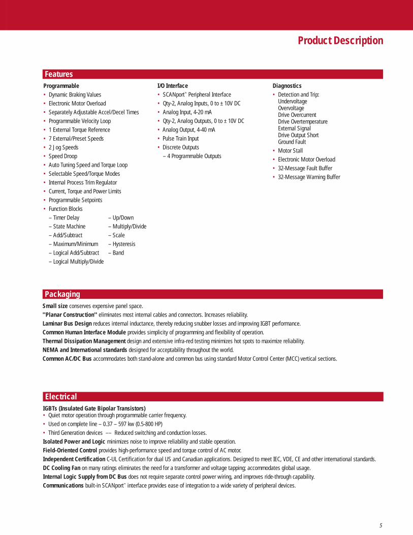
FeaturesDiagnostics• Detection and Trip:
UndervoltageOvervoltageDrive OvercurrentDrive OvertemperatureExternal SignalDrive Output ShortGround Fault
• Motor Stall• Electronic Motor Overload• 32-Message Fault Buffer• 32-Message Warning Buffer
Programmable• Dynamic Braking Values• Electronic Motor Overload• Separately Adjustable Accel/Decel Times• Programmable Velocity Loop• 1 External Torque Reference• 7 External/Preset Speeds• 2 Jog Speeds• Speed Droop• Auto Tuning Speed and Torque Loop• Selectable Speed/Torque Modes• Internal Process Trim Regulator• Current, Torque and Power Limits• Programmable Setpoints• Function Blocks
– Timer Delay – Up/Down– State Machine – Multiply/Divide– Add/Subtract – Scale– Maximum/Minimum – Hysteresis– Logical Add/Subtract – Band– Logical Multiply/Divide
I/O Interface• SCANport™ Peripheral Interface• Qty-2, Analog Inputs, 0 to ± 10V DC• Analog Input, 4-20 mA• Qty-2, Analog Outputs, 0 to ± 10V DC• Analog Output, 4-40 mA• Pulse Train Input• Discrete Outputs
– 4 Programmable Outputs
PackagingSmall size conserves expensive panel space.''Planar Construction'' eliminates most internal cables and connectors. Increases reliability.Laminar Bus Design reduces internal inductance, thereby reducing snubber losses and improving IGBT performance.Common Human Interface Module provides simplicity of programming and flexibility of operation.Thermal Dissipation Management design and extensive infra-red testing minimizes hot spots to maximize reliability.NEMA and International standards designed for acceptability throughout the world.Common AC/DC Bus accommodates both stand-alone and common bus using standard Motor Control Center (MCC) vertical sections.
ElectricalIGBTs (Insulated Gate Bipolar Transistors)• Quiet motor operation through programmable carrier frequency.• Used on complete line – 0.37 – 597 kw (0.5-800 HP)• Third Generation devices –– Reduced switching and conduction losses.Isolated Power and Logic minimizes noise to improve reliability and stable operation.Field-Oriented Control provides high-performance speed and torque control of AC motor.Independent Certification C-UL Certification for dual US and Canadian applications. Designed to meet IEC, VDE, CE and other international standards.DC Cooling Fan on many ratings eliminates the need for a transformer and voltage tapping; accommodates global usage.Internal Logic Supply from DC Bus does not require separate control power wiring, and improves ride-through capability.Communications built-in SCANport™ interface provides ease of integration to a wide variety of peripheral devices.

6
Control SpecificationsCurrent Torque Control Indirect Self-Organized, Field-Oriented Control
Current-regulated, sine-coded PWM with programmable carrier frequency.
Refer to Derating Guidelines on Pages 43 to 51.
Output Voltage Range Three voltage ranges are available. Each voltage range is line dependent and can power a motorbetween the following voltages:200 - 240V AC (line dependent)380 - 480V AC (line dependent)500 - 600V AC (line dependent)If the voltage required for your application is not shown, contact Allen-Bradley for specific information.Note: Due to internal voltage drops in the power structure and voltage margins required for regulation,the drive is unable to produce full output voltage at base speed. If full horsepower is required at orabove base speed, an increase in current is required to produce rated horsepower. This effect willoccur in all drives, but is usually only significant in F, G, and, especially, H frame drives since thevoltage drop is proportional to source inductance and load current.
Output Frequency Range 0 to 250 Hz.
Speed Regulation: With Encoder Feedback: 0.001% of Top Speed Over a 100:1 Speed Range, 1000 to 1 operating range.Encoderless: 0.5% of Top Speed Over a 120:1 typical Speed Range.
Accel/Decel Independently programmable accel and decel times.Program from 0 to 6553 seconds in 0.1 second increments.
Intermittent Overload Capability Constant Torque: 150% of Rated Drive Output for 1 minute. (Not to exceed 150% of Rated Drive Output Limit.)
Current Limit Current Limit programmable to 400% of rated motor current. (May require oversized drive)Independent Motoring and Regenerative Limits.
Inverse Time Overload Capability Class 20 protection with speed-sensitive response.Adjustable from 0-200% of rated output current in 3 speed ranges –– 2:1, 4:1 & 10:1.UL Certified –– Meets NEC Article 430.
AC Input Specifications Voltage Tolerance: -10% of Minimum, +10% of Maximum.Frequency Tolerance: 48-62 Hz.Number of Phases: 3 –– 100% Drive Rating.
1 –– 50% Drive Rating.Refer to Derating Guidelines on Pages 43 to 51.
Displacement Power Factor 0.37-597 kW (0.5 - 800 HP): 0.95
Efficiency 97.5% at rated amps, nominal line volts.
Maximum Short Circuit Current Rating 200,000 A rms symmetrical, 600 volts (when used with AC line fuses specified on Page 32).
Requirements A balanced 3-phase inductive motor load is typical. Drive power rating is based on a typical NEMADesign B, 4- or-6 pole motor. Other motor loads may require application assistance.
Drive CarrierHP Rating Range
7.5-30 HP 4 kHz 1-12 kHz40-60 HP 4 kHz 1-12 kHz75-125 HP 2 kHz 1-6 kHz150-250 HP 2 kHz 1-6 kHz300-650 HP 2 kHz 1-4 kHz600-650 HP 1.5 kHz 1-4 kHz700-800 HP 1 kHz 1-4 kHz
Specifications
Electrical Specifications
Load Specifications

7
Environmental SpecificationsAltitude 1000 m (3300 ft) maximum without derating.
Refer to the Derating Guidelines on Pages 43 to 51.
Ambient Operating Temperature IP00, Open: Chassis –– 0 to 50°C (32 to 122°F).IP20, NEMA Type 1: 0 to 40°C (32 to 104°F).IP65, Nema Type 4: 0 to 40˚C (32 to 104˚F)Refer to Derating Guidelines on Pages 43 to 51.
Storage Temperature (all constructions) – 40 to 70°C (– 40 to 158°F).
Relative Humidity 5 to 95% non-condensing.
Shock 15G peak for 11 ms duration (±1.0 ms).
Vibration 0.006 inches (0.152 mm) displacement, 1G peak.
Agency Certification U.L. Listed
Marked for all applicable directives1
Emissions EN 55011 Class BImmunity EN 50082-1
EN 50082-2IEC 801-2, 3, 4 per EN 50082-1, 2
1 Note: Installation guidelines called out in Appendix E of the 1336 IMPACT User Manual (publication 1336 IMPACT-5.0) must be adhered to.
200-240V Drive 380-480V Drive 500-600V Drive
AC Input Overvoltage Trip 285V AC 570V AC 690V ACAC Input Undervoltage Trip 138V AC 280V AC 343V ACBus Overvoltage Trip 405V DC 810V DC 975V DCBus Undervoltage Trip 200V DC 400V DC 498V DCHeat Sink Thermistor Monitored by microprocessor.
Drive Overcurrent Trip 200% of rated output current.
Line Transients Up to 6000 volts peak per IEEE C62.41-1991.
Control Logic Noise Immunity Showering arc transients up to 1500 volts peak.
Power Ride-Through 15 milliseconds at full load.
Logic Control Ride-Through 0.5 seconds minimum, 2 seconds typical.
Ground Fault Trip Phase-to-Ground on Drive Output.
Short Circuit Trip Phase-to-Phase on Drive Output.
Line Driver Encoder 5V DC or 8-15V DC OutputMinimum Current – 10 mA per channelQuadratureMaximum Input Frequency – 125 kHz
LISTED 56L6
IND CONT EQ®C
Specifications
Protection Specifications
Optional Encoder Inputs

8
Specifications
Input/Output Ratings
1 Drive ratings are at nominal values. Refer to drive Derating Guidelines on Pages 43 to 51.
Requirements Shown below are 1336 IMPACT AC drive input and output current ratings grouped by drive voltage ratings 1.
Input Input Output OutputCat. No. kVA Amps kVA Amps
AQF05 1-1.2 2.8 0.92 2.3AQF07 1.2-1.5 3.5 1.20 3.0AQF10 1.9-2.2 5.4 1.79 4.5AQF15 2.5-3.0 7.3 2.39 6.0AQF20 3.4-4.0 9.7 3.19 8.0AQF30 5.0-5.9 14.3 4.78 12.0AQF50 7.4-8.9 21.3 7.17 18.0A007 10-12 28 11 27.2A010 12-14 35 14 33.7A015 17-20 49 19 48.2A020 23-28 67 26 64.5A025 25-30 73 31 78.2A030 27-30 79 32 80.0A040 43-51 123 48 120.3A050 53-64 154 60 149.2A060 60-72 174 72 180.4A075 82-99 238 96 240.0A100 100-120 289 116 291.4A125 112-135 325 130 327.4
200-240VInput Input Output Output
Cat. No. kVA Amps kVA Amps
BRF05 0.9-1.2 1.4 0.96 1.2BRF07 1.4-1.7 2.1 1.35 1.7BRF10 1.8-2.3 2.8 1.83 2.3BRF15 2.3-2.9 3.5 2.39 3.0BRF20 3.2-4.0 4.8 3.19 4.0BRF30 4.7-6.0 7.2 4.78 6.0BRF50 8-10 12 8.29 10.4BRF75 9-12 14 11.07 13.9BRF100 16-21 25 19.92 25B015 18-23 28 22 27.2B020 23-29 35 27 33.7B025 23-26 43 33 41.8B030 32-41 49 38 48.2BX040 40-50 62 47 58.7B040 41-52 63 52 64.5B050 48-60 75 61 78.2BX060 62 75 61 78.2B060 61-77 93 76 96.9B075 78-99 119 96 120.3B100 98-124 149 120 149.2B125 117-148 178 143 180.4BX150 148 178 143 180.4B150 157-198 238 191 240.0B200 191-241 290 233 291.4B250 212-268 322 259 327.4B300 265-335 403 324 406.4BP300 265-334 402 324 406.4BPR300 265-334 402 324 406.4B350 300-379 455 366 459.2BP350 300-378 455 366 459.2BPR350 300-378 455 366 459.2B400 330-416 501 402 505.1BP400 313-396 476 383 481.0BPR400 313-396 476 383 481.0B450 372-470 565 454 570.2BP450 346-437 526 424 531.7BPR450 346-437 526 424 531.7B500 391-494 594 477 599.2B600 439-555 668 537 673.4B700C 517-625 835 677 850B800C 647-817 965 783 983
380-480VInput Input Output Output
Cat. No. kVA Amps kVA Amps
CWF10 2.6-3.1 3.0 2.49 2.5CWF20 3.5-4.2 4.0 4.18 4.2CWF30 5.2-6.2 6.0 5.98 6.0CWF50 6.9-8.3 8 7.87 7.9CWF75 9-10 10 10 9.9CWF100 10-12 12 12 12.0C015 17-20 19 19 18.9C020 21-26 25 24 23.6C025 27-32 31 30 30.0C030 31-37 36 35 34.6C040 40-48 46 45 45.1C050 48-57 55 57 57.2C060 52-62 60 62 61.6C075 73-88 84 85 85.8C100 94-112 108 109 109.1C125 118-142 137 137 138.6C150 136-163 157 157 159.7C200 217-261 251 251 252.6C250 244-293 282 283 283.6C300 256-307 296 297 298.0CX300 256-307 295 297 298.0C350 304-364 351 352 353.6CP350 301-361 347 349 350CPR350 301-361 347 349 350C400 349-419 403 405 406.4CP400 343-412 397 398 400CPR400 343-412 397 398 400C450 394-473 455 457 459.2C500 434-520 501 503 505.1C600 514-617 594 597 599.2C650 578-694 668 671 673.4C700 616-739 756 767 770C800 639-767 786 797 800
500-600V

9
Specifications/Function Description
Control Inputs
Serial CommunicationsPeripheral Interface SCANport Protocol, up to 6 peripherals can be connected.
Remote I/O Single drop remote I/O to Allen-Bradley PLC® and SLC 500™. Supports full block transfer and link modediscrete transfer.
RS232/422/485 DFI Protocol –– DH485 Protocol –– Customer Specific Protocol.
DeviceNet™ DeviceNet to SCANport module –– Available for all drive ratings.
Flex™ I/O Flex I/O to SCANport module –– Available for all drive ratings.
SLC SLC to SCANport module –– Available for all drive ratings.
ControlNet™ ControlNet to SCANport Module — Available for all drive ratings.
Option L4/L7E Circuits used with Option L4/L7E must be capable of operating at 10mA without signal degradation.Contact Closure Interface Board Requirements Reed type input devices are recommended.
The L4/L7E option is compatible with the following Allen-Bradley PLC modules:• 1771-OYL• 1771-OZLNote: Option L7E is the same as Option L4 but with encoder feedback terminals.
Option L5/L8E Circuits used with Option L5/L8E must be capable of operating with high = true logic.+24V AC/DC Interface Board Requirements DC external circuits in the low state must generate a voltage of no more than 8V DC.
Leakage current must be less than 1.5 mA into a 2.5k Ohm load.AC external circuits in the low state must generate a voltage of no more than 10V DC.Leakage current must be less than 2.5 mA into a 2.5k Ohm load.Both AC and DC external circuits in the high state must generate a voltage of +20 to +26volts and source a current of approximately 10 mA for each input.The L5/L8E option is compatible with these Allen-Bradley PLC® modules:• 1771-OB • 1771-OQ • 1771-OZL• 1771-OBD • 1771-OQ16 • 1771-OBB• 1771-OBN • 1771-OYL • 1771-OB16Note: Option L8E is the same as Option L5 but with encoder feedback terminals.
Option L6/L9E Circuits used with Option L6/L9E must be capable of operating with high = true logic.115V AC Interface Board Requirements In the low state, circuits must generate a voltage of no more than 30V AC. Leakage
current must be less than 10 mA into a 6.5k Ohm load.In the high state, circuits must generate a voltage of 90-115V AC+/-10% and source a current of approximately 20 mA for each input.The L5/L9E option is compatible with these Allen-Bradley PLC modules:• 1771-OW • 1771-OA• 1771-OWN • 1771-OAD (Contact Factory for Recommended Series/Rev. Level)Note: Option L9E is the same as Option L6 but with encoder feedback terminals.
Contact Outputs 115V AC, 30V DC – 8.0 Amp Resistive – 3.5 Amp Inductive.(4) Programmable Contact Outputs.
Control Outputs

10
Function Description
Analog InputsAnalog Input Specifications 4-20 mA, Differential
Resolution: 12 bit, SignedInput Impedance: 130 Ohms
(2) 0 to ± 10V DC, DifferentialResolution: 12 bit, SignedInput Impedance: 20k OhmsDigital scale and offset for each input, definable in firmware.
Analog Output Specifications 4-20 ma, DifferentialResolution: 12 bit, SignedOutput Impedance: 20 Ohms
(2) 0 to ± 10V DC DifferentialResolution: 12 bit, SignedOutput Current: 10 mA maximum per outputOutput Impedance: 100 OhmsDigital Scale and offset, definable in firmware.
Pulse Input Specifications The pulse input signal must be an externally powered square wave pulse train. Differential, 5 or 12V logic level. Maximum frequency of 100 kHz.10 mA minimum.
Analog Outputs
Pulse Reference Input

11
Function Description
FeaturesSimple Start-up
Speed Control
Torque Control
The 1336 IMPACT AC drive provides precise speed control through the use of a high-bandwidth velocity regulator resulting in a speed regulation specification of 0.001% over a 100 to 1 speed range, when using an encoder and an operating speed range of 1000 to 1. Encoderless operation provides a speed regulation specification of 0.5% and up to 120 to 1 speed range.
SpeedReference
FeedForward
SPEED REGULATOR
ProportionGain
IntegralGain
Encoder Feedback
ForwardSpeed Limit
ToTorque
Controller
ReverseSpeed Limit
Startup
Quick Motor Tune?
Enter Motor Data?
Encoder
Regen?
Phase Rotation?
Autotune?InductanceResistance
CurrentInertia
Digital?
Relay
Relay Setpoint
L Option
Outputs
Analog?
Inputs
Torque control is achieved through the use of Field-Oriented Control and current-regulated PWM (CRPWM). The user can program the drive for speed control, torque control, or combinations of both, depending on application. Adjustabletorque, power, and current limits allow maximum flexibility for controlling demanding applications.
Torque
TORQUEMODE
SELECTOR
Max
Sum
Min
FromSpeed Regulator
External TorqueReference
To TorqueController
Speed
The 1336 IMPACT drive provides a menu driven start-up procedurethat leads you through entering the motor nameplate informationand running the auto-tune tests. It also sets up the digital I/O byhelping you configure the relay output and L Option Card, and setsup the analog I/O by helping you create links between the I/O andreferences. When the start-up procedure is complete, the drive should be set to perform basic functions.Auto-Tuning – Speed. The auto-tuning feature allows the drive to tune the speed loop to the connected load without the use ofcomplicated formulas or procedures. The drive tests for motor inertia(motor disconnected from load), system inertia, and system friction.This information is then used to tune the speed loop.Auto-Tuning – Torque Loop. The 1336 IMPACT AC drive tunes thetorque loop to the motor without any special equipment or hard-to-find motor information. This unique feature allows the 1336 IMPACTdrive to be used with most motors.

12
Function Description
Motor Temperature Compensation
Process Trim Controller
Torque, Power, and Current Limits
Fault Diagnostics
Filter
Limit
To TorqueRegulator
Process TrimReference
Process TrimFeedback
ProcessTrimRegulator
TrimTorque
TrimSpeed
To Speed Regulator
TorqueCommand Motor
CurrentCommand
PositiveTorque
NegativeTorque
Motoring PowerLimit
Regen PowerLimit
TorqueLimit Current
Limit
NegativeCurrentLimit
PositiveCurrentLimit
Speed Feedback
FAULT FAULTCODE MESSAGE02016 Overvoltage02018 Ground Fault03025 Absolute Overspeed
FAULT BUFFER
WARNING BUFFER
123•••32
WARNING WARNINGCODE MESSAGE01083 Motor Overload Pend05086 External Fault In01085 Motor Stalled
123•••32
MotorTemperature
Compensationactivated
150
125
100
75
50
25
Time
Actual Torque Desired Torque
Torque
The 1336 IMPACT AC drive has advanced fault diagnosticcapabilities that enable the user to quickly diagnose and troubleshoot the drive. All faults are stored in non-volatile memory. Drive faults are categorized as either Trip- or Warning-type faults.When a fault occurs, a fault time stamp provides the relative time data.Trip faults cause drive shutdown. A fault message is displayed on program terminals and fault status is also available to any device connected to or monitoring the drive. These faults are defined as either hard or soft faults.Warning faults are indicated to devices connected to the drive but do not cause an immediate drive shutdown. This enables the user to take corrective action without unwanted nuisance shutdowns. Some warning faults can be programmed as Trip faults, or completely disabled.A separate Trip fault buffer and Warning fault buffer store the last 32 messages that have occurred. These buffers are maintained in non-volatile memory. Separate clear fault and clear buffer capabilities are built-in.
Separate limit parameters provide maximum flexibility to control the motor torque output, power output, and total motor current. Each set of limits is independently programmable and has separate adjustments for motoring and regenerative regions.
As motor temperature changes, the torque output of the motorchanges. Typically, a motor temperature sensor is placed in the motor and used by the drive to maintain better control of torque. The 1336 IMPACT AC drive automatically compensates for changing motor temperature without the need for a special, motor-mounted temperature sensor.
A process trim controller is built into the 1336 IMPACT AC drive. Transducers, such as dancers or load cells, can be connected directly to the drive and used to trim either the speed or torque output of the the drive.

13
Function Description
Owners
Masks
Braking Features
DC Bus Options
Function Blocks
All external control connections to the 1336 IMPACT AC driveare made through a multi-connection communication bus called SCANport. With the possibility of many devices able to issue drive control functions (start, stop, reverse, speed reference, etc.),the 1336 IMPACT AC drive offers a mask for each control function that gives you complete flexibility to lock out any function (except stop) from any port.
There are several choices for braking or decelerating the load with a 1336 IMPACT drive. These include an external Dynamic Brake, Brake Chopper kits or other regenerative method. When these are not present, the choices are Flux Braking, DC Braking or Bus Regulator. Select these options through firmware.Flux Braking increases the motor flux current, which increases motor losses. The higher losses produce a shorter motor deceleration time.DC Braking applies a DC current to the motor and becomes active only during a stop command. The amount of current applied is programmable and willaffect the stopping time.Bus Regulator is part of DC Bus Options and used to limit or control the bus voltage when decelerating or as regeneration occurs. At high bus voltage,the regulator becomes active and reduces the regenerative power limit to control bus voltage.
DC bus options provide bus control and sensing adjustability for ride through on line loss. Without a brake, the DC bus regulator will help prevent busover voltage trips by reducing the regenerative torque.
For applications requiring additional flexibility, the 1336 IMPACT drive has function blocks. This allows customizing of the drive operation by selecting one of eleven different functions. Functions available are a timer delay, state machine, add/subtract,maximum/minimum, up/down counter, multiply/divide, scale hysteresis,band, logical add/subtract, and logical multiply/divide block.To use the state machine function block as an example, it defines a decision table. This table selects which value to use for the output,based on the values of the inputs.
The 1336 IMPACT AC drive displays which of the available SCANport ports currently “owns” certain control functions. To avoidconflict, some owners are exclusive (only one device can issue areference), while others can have multiple control (many devices can simultaneously issue a start command). Owner displays are excellent diagnostic tools, displaying precisely where drive controlcommands originate.
Indicates current speedcommand is issued fromSCANport port 1 –– LocalHuman Interface Module
Port
Port
Typical Owner Reference Source
0100000001234567
Allows jog from Adapter 1Denies jog from Adapter 3
Typical Jog Mask
1110111101234567
Func 1 Eval Sel
Func 2 Eval Sel
Func 3 Eval Sel
Function Sel212
212
19881
199
10
203
20181
202
10
206
207
213
8
197
208
209
210
211
204
2050
Motor Speed Function In1
Func 1 Mask/Val
Motor Speed Function In2
Function In4
Logic CmdInput
FunctionOutput 1
Function In5
Function In6
Function In7
Function In8
Function In3
Func 2 Mask/Val
Func 3 Mask/Val
In1 is true ifMotor Speed > 4000
In1 is true ifMotor Speed > 1024
In3 = 0Enter: 0
Enter: 0
Enter: 0.17 minutes (10 seconds)
Enter: 0 This value is not used
Enter: 00000010.00000000
Enter: 00000010.00000001
Enter: 0 This value is not used
State Machine Function Block
And In1Timer is:FalseTrueFalseTrue
If In2 is:FalseFalseTrueTrue
Then thisoutput is used:In3 — 0In6 — Not usedIn7 — Ramp DisableIn8 — Ramp Disable Stop

14
1336 IMPACT AC Drive Pre-Installation
This Frame Reference Guide is referred to throughout this publication to provide a frame break referencefor various options and drive ratings. Actual frame dimensions are given on the following (5) pages.
200-240V Drives 380-480V Drives 500-600V Drives Frame Designation
0.37-0.75 kW 0.37-1.2 kW — A1(0.5-1 HP) (0.5-1.5 HP) —
1.2-1.5 kW 1.5-2.2 kW — A2(1.5-2 HP) (2-3 HP) —
2.2-3.7 kW 3.7 kW — A3(3-5 HP) (5 HP) —
— 5.5-7.5 kW 0.75-3.7 kW A4— (7.5-10 HP) (1-10 HP)
5.5-11 kW 11-22 kW 11-15 kW B(7.5-15 HP) (15-30 HP) (15-20 HP)
15-22 kW 30-45 kW 18.5-45 kW C(20-30 HP) (40-60 HP) (25-60 HP)
30-45 kW 45-112 kW 56-93 kW D(40-60 HP) (60-150 HP) (75-125 HP)
56-75 kW 112-187 kW 112-224 kW E(75-125 HP) (150-250 HP) (150-300 HP)
— 224-336 kW 261-336 kW F— (300-450 HP) (350-450 HP)
— 224-448 kW 224-485 kW G— (300-600 HP) (300-650 HP)
— 522-597 kW 522-597 kW H— (700-800 HP) (700-800 HP)
ATTENTION: The following information is merely a guide for proper installation. The Allen-Bradley Company cannot assume responsibility for the compliance or the noncompliance to any code, national, local or otherwise for the proper installation of this drive or associated equipment. A hazard of personal injury and/or equipment exists if codes are ignored during installation.
!
Frame Reference Guide

15
1336 IMPACT AC Drive Pre-Installation
IP20 (NEMA Type 1) Dimensions — Frames A1, A2, A3 and A4
C Max.D
A
Y
CC
E B
Z
BB
AA
Mounting Holes (4) – See Detail
7.0 (0.28)
7.0 (0.28)
12.7 (0.50)
12.7 (0.50)
Mounting Hole Detail
Bottom View Will Vary with HP – See Bottom View Dimensions
TECHNOLOGY
Frame ShippingReference A B C Max D E Y Z AA BB CC Weights
A1 215.9 290.0 160.0 185.2 275.0 15.35 7.5 130.0 76.2 85.3 4.31 kg(8.50) (11.42) (6.30) (7.29) (10.83) (0.60) (0.30) (5.12) (3.00) (3.36) (9.5 lbs)
A2 215.9 290.0 180.5 185.2 275.0 15.35 7.5 130.0 76.2 85.3 5.49 kg(8.50) (11.42) (7.10) (7.29) (10.83) (0.60) (0.30) (5.12) (3.00) (3.36) (12.1 lbs)
A3 215.9 290.0 207.0 185.2 275.0 15.35 7.5 130.0 76.2 85.3 6.71 kg(8.50) (11.42) (8.15) (7.29) (10.83) (0.60) (0.30) (5.12) (3.00) (3.36) (14.8 lbs)
A4 260.0 350.0 212.0 230.0 320.0 15.35 15.35 130.0 133.0 86.0 15.90 kg(10.24) (13.78) (8.35) (9.06) (12.60) (0.60) (0.60) (5.12) (5.23) (3.39) (35.0 lbs)
Three-Phase Rating FrameReference200 – 240V 380 – 480V 500 – 600V
0.37 – 0.75 kW0.5 – 1 HP
0.37 – 1.2 kW0.5 – 1.5 HP
—
1.2 – 1.5 kW1.5 – 2 HP
1.5 – 2.2 kW2 – 3 HP
—
2.2 – 3.7 kW3 – 5 HP
3.7 kW5 HP
—
—5.5 – 7.5 kW7.5 – 10 HP
0.75 – 7.5 kW1 – 10 HP
A4
A3
A2
A1
5.5 – 11 kW7.5 – 15 HP
11 – 22 kW15 – 30 HP
11 – 15 kW15 – 20 HP
B
15 – 22 kW20 – 30 HP
30 – 45 kW40 – 60 HP
18.5 – 45 kW25 – 60 HP
C
30 – 45 kW40 – 60 HP
45 – 112 kW60 – 150 HP
56 – 93 kW75 – 125 HP
D
56 – 93 kW75 – 125 HP
112 – 187 kW150 – 250 HP
112 – 187 kW150 – 250 HP
E
— 224 – 336 kW300 – 450 HP
261 – 336 kW350 – 450 HP
F
Use care when choosing Frame Reference — some ratings mayexist in another frame size.
— 187 – 448 kW300 – 600 HP
224 – 485 kW300 – 650 HP
GAll Dimensions in Millimeters and (Inches)All Weights in Kilograms and (Pounds)

16
1336 IMPACT AC Drive Pre-Installation
IP 20 (NEMA Type 1) Dimensions — Frames B, C and D
Bottom View Will Vary with HP – See Bottom View Dimensions
C Max.D
A
Y
CC
E B
Z
BB
AA
7.1 (0.28)
7.1 (0.28)
12.7 (0.50)
12.7 (0.50)
R 5.2 (0.20)
14.7 (0.58)
R 9.5 (0.38)
Mounting Hole Detail(Frames B & C)
Mounting Hole Detail(Frame D)
Mounting Holes (4) – See Detail
Frame1Reference A B C Max. D E Y Z AA BB CC
ShippingWeight
B276.4(10.88)
476.3(18.75)
225.0(8.86)
212.6(8.37)
461.0(18.15)
32.00(1.26)
7.6(0.30)
131.1(5.16)
180.8(7.12)
71.9(2.83)
22.7 kg(50 lbs)
C301.8(11.88)
701.0(27.60)
225.0(8.86)
238.0(9.37)
685.8(27.00)
32.00(1.26)
7.6(0.30)
131.1(5.16)
374.7(14.75)
71.9(2.83)
38.6 kg(85 lbs)
D381.5(15.02)
1240.0(48.82)
270.8(10.66)
325.9(12.83)
1216.2(47.88)
27.94(1.10)
11.94(0.47)
131.1(5.16)
688.6(27.11)
83.6(3.29)
108.9 kg(240 lbs)
All Dimensions in Milimeters and (Inches)All Weights in Kilograms and (Pounds).
1 Refer to the Derating Guidelines on Pages 43 to 51 for derating information.

17
1336 IMPACT AC Drive Pre-Installation
IP20 (NEMA Type 1) Dimensions — Frame E
C Max.D
A
Y
CC
E B
Z
BB
AA
Mounting Holes (4) – See Detail
37.9(1.49)
Mounting Hole Detail
See Bottom View Dimensions for Details
Dia. 10.2 (0.40)
17.0 (0.67)
Dia. 19.1 (0.75)
Frame1Reference A B C Max. D E Y Z AA BB CC
ShippingWeight
E — Enclosed511.0(20.12)
1498.6(59.00)
424.4(16.71)
477.5(18.80)
1447.8(57.00)
16.8(0.66)
40.1(1.61)
195.0(7.68)
901.4(35.49)
151.9(5.98)
186 kg(410 lbs)
E — Open511.0(20.12)
1498.6(59.00)
372.6(14.67)
477.5(18.80)
1447.8(57.00)
16.8(0.66)
40.1(1.61)
138.4(5.45)
680.0(26.77)
126.3(4.97)
163 kg(360 lbs)
All Dimensions in Milimeters and (Inches).All Weights in Kilograms and (Pounds).
1 Refer to the Derating Guidelines on Pages 43 to 51 for derating information.

18
1336 IMPACT AC Drive Pre-Installation
IP 20 (NEMA Type 1) Dimensions — Frame F
2286.0(90.00)
762.0(30.00)
252.7(9.95)
635.0(25.00)
37.9(1.49)
274.8(10.82)
193.0(7.60)
1219.2(48.00)
All Dimensions in Millimeters and (Inches)
ConduitAccess Area
Bottom View
31.5(1.24)
698.5(27.50)
298.5(11.75)
50.8(2.00)
For Frame Reference refer to the Derating Guidelines on Pages 43 to 51 for derating information.

19
1336 IMPACT AC Drive Pre-Installation
Open Dimensions — Frame F ”Roll-in“ Chassis
DANGER
DANGER
DANGER
DANGER
DANGER
DANGER
T-L3R-L1 S-L2 W-M3
TE
U-M1PE V-M2
717.6(28.25)
463.6(18.25)
635.0(25.00)
1543.3(60.76)
All Dimensions in Millimeters and (Inches)
For Frame Reference refer to the Derating Guidelines on Pages 43 to 51 for derating information.

20
1336 IMPACT AC Drive Pre-Installation
FeaturesIP 20 (NEMA Type 1) Dimensions — Frame G
For Frame Reference refer to the Derating Guidelines on Pages 43 to 51 for derating information.
2324.1(91.50)
Removable Lifting Angle
762.0(30.00)
Open Chassis Dimensions
635.0(25.00)
63.5 (2.50)
648.0(25.51)19.3
(0.76)
1524.0(60.00)
117.3(4.62)
Depth = 508.3 (20.01)Weight = 453.6 kg (1000 lbs.)
All Dimensions in Millimeters and (Inches)
n
Important: Two (2) 725 CFM fans are required if an open type drive is mounted in a user supplied enclosure.
Bottom View
Top View
29.0 (1.14)
15.9 (0.63) Dia. - 2 Mtg. Holes
431.8(17.00)
381.0(15.00)
298.5(11.75)
42.9(1.69)
254.0(10.00)547.6
(21.56)
ConduitAccess Area
Conduit Access Area
660.4 (26.00) 50.8 (2.00)
431.8(17.00)

21
1336 IMPACT AC Drive Pre-Installation
IP 20 (NEMA Type 1) Dimensions — Frame H
For Frame Reference refer to the Derating Guidelines on Pages 43 to 51 for derating information.
Removable Lifting Angle
2324.1(91.50)
All Dimensions in Millimeters and (Inches)
635.0(25)
508.0(20)
762.0(30)
Conduit AccessArea
Conduit AccessArea
Top ViewBottom View
Top Mounted FanShipped Loose for
Customer Installation635.0
(25.00)
1270.0(50)
1270.0(50)
635.0(25)
Manufacturer-dependent,may be shorter.
Front
Proper Fan Rotation(Counter-clockwise when
viewed from the top)
Proper Fan Rotation(Fan not visible when viewed from the top)

22
1336 IMPACT AC Drive Pre-Installation
Bottom View Dimensions — Frames A1 - E
For Frame Reference refer to the Derating Guidelines on Pages 43 to 51 for derating information.
Frames A1 through A4
MN L
QR
P
S
22.2/28.6 (0.88/1.13)Conduit Knockout - 3 Plcs.
22.2 (0.88) Conduit Knockout - 1 Plc.
Fans will be present on A4 Frame
FrameReference L NM P Q R S
A1111.8(4.40)
105.4(4.15)
86.3(3.40)
25.4(1.00)
63.2(2.49)
102.1(4.02)
135.4(5.33)
A2132.3(5.21)
126.0(4.96)
106.9(4.21)
25.4(1.00)
63.2(2.49)
102.1(4.02)
135.4(5.33)
A3158.8(6.25)
152.4(6.00)
133.4(5.25)
25.4(1.00)
63.2(2.49)
102.1(4.02)
135.4(5.33)
A4164.0(6.45)
164.0(6.45)
139.0(5.47)
27.0(1.06)
65.0(2.65)
97.0(3.82)
128.7(5.07)
All Dimensions in Millimeters and (Inches).
FrameReference L PM Q R S
B181.6(7.15)
167.1(6.58)
112.8(4.44)
163.6(6.44)
214.4(8.44)
249.9(9.84)
C181.6(7.15)
167.1(6.58)
119.1(4.69)
182.6(7.19)
227.1(8.94)
275.3(10.84)
Frames B and C
LM
QR
P
S
28.6/34.9 (1.13/1.38)Conduit Knockout - 3 Plcs.
22.2 (0.88)Conduit Knockout - 1 Plc.
SR
Q P
T
88.9/101.6(3.50/4.00)Conduit Knockout - 3 Plcs.
12.7 (0.50)ConduitKnockout -6 Plcs.
N
Frame E
Frame DS
RQ
P
L
JK
N
M
L
M
34.9 (1.38)Conduit Knockout - 3 Plcs.
34.9/50.0(1.38/1.97)ConduitKnockout - 1 Plc.
62.7/76.2 (2.47/3.00)Conduit Knockout - 2 Plcs. Frame
Reference L NM P Q R S
D131.6(5.18)
K
169.4(6.67)
J
198.1(7.80)
153.7(6.05)
204.5(8.05)
52.1(2.05)
144.0(5.67)
261.4(10.29)
343.9(13.54)
FrameReference L NM P Q R T
E311.2(12.25)
260.4(10.25)
209.6(8.25)
50.8(2.0)
38.6(1.52)
178.3(7.02)
432.3(17.02)
S
305.3(12.02)

23
1336 IMPACT AC Drive Pre-Installation
1336 IMPACT drives are suitable for use on a circuit capable of delivering up to a maximum of 200,000 rms symmetrical amperes, 600 volts maximumwhen used with the AC input line fuses specified on Page 32.
AC Supply Source
Mounting and Spacing Requirements
In general, the 1336 IMPACT drive is suitable for direct connection to a correct voltage AC line that has a minimum impedance of 1% (3% for0.37-22 kW/0.5-30 HP drives) relative to the rated drive input kVA. If the line has a lower impedance, a line reactor or isolation transformermust be added before the drive to increase line impedance. If the line impedance is too low, transient voltage spikes or interruptions cancreate excessive current spikes that will cause nuisance input fuse blowing and may cause damage to the drive power structure.The basic rules for determining if a line reactor or isolation type transformer is required are as follows:
1. If the AC input power system does not have a neutral or one phase referenced to ground (Refer to Ungrounded Distribution Systems), an isolation transformer with the neutral of the secondary grounded is highly recommended. If the line-to-ground voltages on any phase can exceed 125% of the nominal line-to-line voltage, an isolation transformer with the neutral of the secondary grounded, isalways required.
2. If the AC line supplying the drive has power factor correction capacitors that are switched in and out, an isolation transformer or 5%reactors are recommended between the capacitors and drive. If the capacitors are permanently connected and not switched, the generalrules for impedance mismatch above apply.
3. If the AC line frequently experiences transient power interruptions or significant voltage spikes, an isolation transformer or 5% reactorsare recommended.
Line reactors and isolation transformers can be ordered as loose items or installed in the drive enclosure.
101.6 mm(4.0 in.)
Not Acceptable
NOT ACCEPTABLE 1
Approved Mounting Method Approved Mounting Method
Approved Mounting Method
Approved Mounting Methods for Wall Mounting Enclosures
NO
T A
CCEP
TAB
LE
➮ 152.4 mm(6.0 In.)
➮
152.4 mm(6.0 In.)
➮
152.4 mm(6.0 In.)
➮➮
152.4 mm(6.0 in.) ➮ ➮
Input Conditioning
1 Some horizontal mounting conventions are acceptableprovided the application and packaging is reviewed withAllen-Bradley.
FLOOR
CEILING
Approved Mounting Methods for Floor Mounting Enclosures
• All Floor Mounting Style Enclosures can be mounted tight against the back wall.
• NEMA Type 1 Floor Mounting Style (Force ventilated as standard) may be mounted side by side with zero clearance.
• NEMA Type 12 Floor Mounting Style Enclosureswill require six inch clearance on the sides.

24
1336 IMPACT AC Drive Pre-Installation
Typical Component and Terminal Block Locations
Power Wiring
ATTENTION: The hazard for injury or death from electric shock may exist if a disconnectingmeans is wired to drive output terminals and is opened during drive operation.Any disconnecting means wired to drive output terminals U, V, and W must becapable of disabling the drive if opened during drive operation. An auxiliarycontact must be used to simultaneously disable the drive.
Input and output power connections are performed through terminal block, TB1. For maintenance and setup procedures, the drive may be operated withouta motor connected.
!
ATTENTION: The national codes and standards (NEC, VDE, BSA, etc.) and local codes outlineprovisions for safely installing electrical equipment. Installation must complywith specifications regarding wire type, conductor sizes, branch circuitprotection, and disconnect devices. Failure to do so may result in personal injuryand/or equipment damage.
!
ATTENTION: If you install control and signal wiring with an insulation rating of less than600V, you must route this wiring inside the drive enclosure so that it isseparated from any other wiring and uninsulated live parts. If you do notseparate these wires, you may damage your equipment or have unsatisfactorydrive performance.
!
Power Terminal BlockControl & Signal WiringControl Interface Option24V DC Auxiliary InputHigh Voltage DC Auxiliary Input480V Output (F Frame Only)Shield Terminals
TB1TB10, 11TB3TB4TB6TB9TE
TB1TB11TB3
TB4TB6
Frames B, C Frames D, E
TB1
TB11
TB3Control Interface
Option
Control InterfaceOption
TB1
TB1Location
TB4
TE
TB10
TB10
TB1 LocationTB1
Frame F
BrakeTerminals
TETB10, 11
TB3
TB9
Frame G
U, V, W& BrakeTerminals
TB10, 11
TB3
R, S, T
TE
PEGround
TB1Location
Frame H (Preliminary)
U, V, W& BrakeTerminals
TB10, 11
TB3
+, -
TE
PE Ground
TB1Location
TB3
TB4
TB10
Power Terminal BlockControl & Signal WiringControl Interface Option
TB1TB4, 7, 10TB3
Frame Reference A1-A4
TB1
Cont
rol I
nter
face
Optio
n
TB7

25
1336 IMPACT AC Drive Pre-Installation
Input Fuses and Circuit Breakers1336 IMPACT drive can be installed with either input fuses or an input circuit breaker. Local/national electrical codes may determine additionalrequirements for these installations.
FusesIn general, the specified fuses are suitable for branch short circuit protection and provide excellent short circuit protection for the drive. The fuses offer ahigh interrupting capacity and are fast acting. Refer to the North American selections in the table on Page 32.Circuit BreakersThe Westinghouse HMCP breakers specified in the table on Page 26-27 also provide branch short circuit protection. Because circuit breakers are typicallyslower than fuses and those listed are magnetic trip only, they may not be as effective in offering short circuit protection to the drive in the event of aninternal drive short circit. They may not be as effective in limiting damage to the drive.
FusesFor those installations that are not required to meet the U.S. NEC/UL/CSA, the specified fuses are suitable for branch short circuit protection and provideexcellent short circuit protection for the drive. The fuses offer a high interrupting capacity and are fast acting. Refer to the European selections in the tableon Page 32.Circuit BreakersFor those installations that are not required to meet the U.S. NEC/UL/CSA requirements, additional devices are available as input circuit breakers. TheBulletin 140 and KTA3 devices meet the circuit breaker requirements of IEC947-2, but do not meet UL/CSA circuit breaker requirements. They can be usedin “non-U.S.” installations where local/national codes allow, if they are installed per their installation instructions.
Installations Per U.S. NEC/UL/CSA
IEC Installations
ATTENTION: The 1336 IMPACT drive does not provide input power short circuit protection. Specifications for the recommended fuse or circuit breaker toprovide drive input power protection against short circuits are provided.!

26
1336 IMPACT AC Drive Pre-Installation
Recommended AC Line Circuit Breakers (user supplied)
IEC Installations per IEC947-2 UL/CSA InstallationsMaximum Bulletin 140 Circuit Breaker1 HMCP Circuit Breaker2
Drive Rated VT Rated Service Short MCP Trip Max. ShortCatalog Number kW (HP) Catalog Number Circuit Capability Catalog Number Setting Circuit Amps3
400/415V 480V1336E-AQF05 0.37 (0.5) 140-MN-0400 100,000 HMCPS007C0 H 65,0001336E-AQF07 0.56 (0.75) 140-MN-0400 100,000 HMCPS015E0C E 65,0001336E-AQF10 0.75 (1) 140-MN-0630 100,000 HMCPS015E0C E 65,0001336E-AQF15 1.2 (1.5) 140-MN-1000 16,000 HMCPS015E0C F 65,0001336E-AQF20 1.5 (2) 140-MN-1000 16,000 HMCPS030H1C E 65,0001336E-AQF30 2.2 (3) 140-MN-1600 6,000 HMCPS030H1C F 65,0001336E-AQF50 3.7 (5) 140-MN-2500 6,000 HMCPS030H1C H 65,0001336E-A007 5.5 (7.5) 140-CMN-4000 65,000 HMCPS030H1C H 65,0001336E-A010 7.5 (10) 140-CMN-4000 65,000 HMCPS050K2C F 65,0001336E-A015 11 (15) 140-CMN-6300 50,000 HMCPS050K2C H 65,0001336E-A020 15 (20) 140-CMN-6300 50,000 HMCPS100R3C G 65,0001336E-A025 18.5 (25) 140-CMN-9000 25,000 HMCPS100R3C H 65,0001336E-A030 22 (30) 140-CMN-9000 25,000 HMCPS100R3C H 65,0001336E-A040 30 (40) KTA3-160S-125 65,000 HMCP150T4C F 65,0001336E-A050 37 (50) KTA3-160S-160 65,000 HMCP150T4C G 65,0001336E-A060 45 (60) KTA3-250S-200 65,000 HMCP250A5 E 65,0001336E-A075 56 (75) KTA3-250S-250 65,000 HMCP250A5 E 65,0001336E-A100 75 (100) KTA3-400S-320 65,000 HMCP400J5 I 65,0001336E-A125 93 (125) KTA3-400S-320 65,000 HMCP400J5 I 65,0001336E-BRF05 0.37 (0.5) 140-MN-0250 100,000 HMCPS003A0 E 65,0001336E-BRF07 0.56 (0.75) 140-MN-0250 100,000 HMCPS003A0 G 65,0001336E-BRF10 0.75 (1) 140-MN-0400 100,000 HMCPS003A0 G 65,0001336E-BRF15 1.2 (1.5) 140-MN-0400 100,000 HMCPS007C0 B 65,0001336E-BRF20 1.5 (2) 140-MN-0630 100,000 HMCPS007C0 C 65,0001336E-BRF30 2.2 (3) 140-MN-1000 16,000 HMCPS015E0C B 65,0001336E-BRF50 3.7 (5) 140-MN-1000 16,000 HMCPS015E0C D 65,0001336E-BRF75 5.5 (7.5) 140-MN-1600 6,000 HMCPS015E0C H 65,0001336E-BRF100 7.5 (10) 140-MN-2000 6,000 HMCPS030H1C H 65,0001336E-B010 11 (15) 140-MN-2000 6,000 HMCPS030H1C E 65,0001336E-B015 15 (20) 140-MN-2500 6,000 HMCPS030H1C H 65,0001336E-B020 18.5 (25) 140-CMN-4000 65,000 HMCPS050K2C H 65,0001336E-B025 22 (30) 140-CMN-4000 65,000 HMCPS050K2C H 65,0001336E-B030 22 (30) 140-CMN-6300 50,000 HMCPS050K2C H 65,0001336E-BX040 30 (40) 140-CMN-6300 50,000 HMCPS050K2C H 65,0001336E-B040 37 (50) 140-CMN-6300 50,000 HMCPS100R3C G 65,0001336E-B050 45 (60) 140-CMN-9000 25,000 HMCPS100R3C G 65,0001336E-BX060 45 (60) 140-CMN-9000 25,000 HMCPS100R3C G 65,0001336E-B060 56 (75) KTA3-160S-125 65,000 HMCPS150T4C F 65,0001336E-B075 75 (100) KTA3-160S-125 65,000 HMCPS150T4C H 65,0001336E-B100 93 (125) KTA3-160S-160 65,000 HMCPS150U4C E 65,0001336E-B125 112 (150) KTA3-250S-200 65,000 HMCP250K5 H 65,0001336E-BX150 112 (150) KTA3-250S-200 65,000 HMCP250K5 H 65,0001336E-B150 149 (200) KTA3-400S-320 65,000 HMCP250L5 I 65,0001336E-B200 187 (250) KTA3-400S-320 65,000 HMCP400N5 H 65,0001336E-B250 224 (300) KTA3-400S-400 65,000 HMCP400N5 I 65,0001336E-BP250 224 (300) KTA3-400S-400 65,000 HMCP400R5 I 65,0001336E-B300 261 (350) NA — NA — —1336E-BP300 261 (350) KTA3-400S-400 65,000 HMCP400R5 I 65,0001336E-B350 298 (400) NA — —1336E-BP350 261 (350) HMCP600L6W E 65,0001336E-B400 336 (450) NA — —1336E-BP400 298 (400) HMCP600L6W E 65,0001336E-B450 373 (500) NA — —1336E-BP450 336 (450) HMCP600L6W E 65,0001336E-B500 448 (600) NA — —1336E-B600 448 (600) NA — —
NA

27
1336 IMPACT AC Drive Pre-Installation
Recommended AC Line Circuit Breakers (user supplied) (continued)
IEC Installations per IEC947-2 UL/CSA InstallationsMaximum Bulletin 140 Circuit Breaker1 HMCP Circuit Breaker2
Drive Rated VT Rated Service Short MCP Trip Max. ShortCatalog Number kW (HP) Catalog Number Circuit Capability Catalog Number Setting Circuit Amps3
400/415V 480V1336E-C001 0.75 (1) 140-MN-0400 100,000 HMCPS003A0 E 65,0001336E-C003 2.2 (3) 140-MN-0630 100,000 HMCPS007C0 E 65,0001336E-C007 5.5 (7.5) 140-MN-1000 16,000 HMCPS015E0C E 65,0001336E-C010 7.5 (10) 140-MN-1600 6,000 HMCPS015E0C E 65,0001336E-C015 11 (15) 140-MN-2000 6,000 HMCPS030H1C F 65,0001336E-C020 15 (20) 140-MN-2500 6,000 HMCPS030H1C H 65,0001336E-C025 18.5 (25) 140-CMN-4000 65,000 HMCPS050K2C E 65,0001336E-C030 22 (30) 140-CMN-4000 65,000 HMCPS050K2C G 65,0001336E-C040 30 (40) 140-CMN-6300 50,000 HMCPS050K2C G 65,0001336E-C050 37 (50) 140-CMN-6300 50,000 HMCPS100R3C E 65,0001336E-C060 45 (60) 140-CMN-6300 50,000 HMCPS100R3C E 65,0001336E-C075 56 (75) 140-CMN-9000 25,000 HMCPS100R3C G 65,0001336E-C100 75 (100) KTA3-160S-125 65,000 HMCP150T4C E 65,0001336E-C125 93 (125) KTA3-160S-160 65,000 HMCP150T4C E 65,0001336E-C150 112 (150) KTA3-400S-160 65,000 HMCP250J5 G 65,0001336E-C200 149 (200) KTA3-400S-320 65,000 HMCP250K5 I 65,0001336E-C250 187 (250) KTA3-400S-320 65,000 HMCP400W5 G 65,0001336E-CX300 224 (300) KTA3-400S-320 65,000 HMCP400W5 H 65,0001336E-C300 224 (300) KTA3-400S-320 65,0001336E-C350 261 (350) KTA3-400S-400 65,0001336E-C400 298 (400) KTA3-400S-400 65,0001336E-C450 336 (450)1336E-C500 373 (500)1336E-C600 448 (600)
NA
NA
NA = Not Available – No device exists, uses fuses shown on Page 32.1 Bulletin 140 – At 480 volts, circuit breaker must have a fuse backup. Refer to the AB Industrial Control Catalog. At 600 volts, additional restrictions apply.
Not limitations in source short circuit ratings.2 HMCP Circuit Breaker – HMCP Breaker is a magnetic trip device only. Always set the trip setting as low as possible in a particular application.
Note information in HMCP application handbook.3 Current limiting option can extend this value to 200,000A RMS.

28
1336 IMPACT AC Drive Pre-Installation
Power Wiring — TB1
PE PE R(L1)
S(L2)
T(L3)
U(T1)
V(T2)
W(T3)
DC+
DC–
RequiredInput Fusing
AC Input Line
To Motor
200-240V, 7.5-11 kW (10-15 HP) Terminal Designations380-480V, 15-22 kW (20-30 HP) Terminal Designations
500-600V, 15 kW (20 HP) Terminal Designations
Dynamic Brake
To Motor1
B2 Frame
1 Required BranchCircuit Disconnect
PE PE R(L1)
S(L2)
T(L3)
U(T1)
V(T2)
W(T3)
DC+
DC–
AC Input Line
To MotorTo Motor
200-240V, 5.5 kW (7.5 HP) Terminal Designations380-480/500-600V, 5.5-11 kW (15 HP) Terminal Designations
Dynamic Brake
RequiredInput Fusing
1
B1 Frame
1 Required BranchCircuit Disconnect
PEGRD
PEGRD
DC+
Dynamic Brake
RequiredInput Fusing
1
DC–
R(L1)
S(L2)
T(L3)
W(T3)
U(T1)
V(T2)
To Motor
AC Input Line
200-240V, 15-22 kW (20-30 HP) Terminal Designations380-480V, 30-45 kW (40-60 HP) Terminal Designations
500-600V, 18.5-45 kW (25-60 HP) Terminal Designations
C Frame
1 Required BranchCircuit DisconnectTo Motor
GRD GRDGRD GRD R(L1)
S(L2)
T(L3)
DC+
BRK 2–
DC–
COM
U(T1)
V(T2)
W(T3)
AC Input Line
To Motor
380-480V, 5.5-7.5 kW (7.5-10 HP) Terminal Designations500-600V, 0.75-7.5 kW (1-10 HP) Terminal Designations
To Motor
2 Dynamic Brake
RequiredInput Fusing
1
To Motor
RequiredInput Fusing
1
A4 Frame
1 Required BranchCircuit Disconnect
R(L1)
S(L2)
T(L3)
DC+
DC–
U(T1)
V(T2)
W(T3)
AC Input Line
To Motor
200-240V, 0.37-3.7 kW (0.5-5 HP) Terminal Designations380-480V, 0.37-3.7 kW (0.5-5 HP) Terminal Designations
Dynamic BrakeOption
DC Input Line
A1-A3 Frame
1 Required BranchCircuit Disconnect
1 User supplied.2 Before wiring your dynamic brake for
the A4 frame, double check theterminals. You should attach the +terminal on the brake to the DC+terminal on your drive and the -terminal on the brake to the BRK -terminal on your drive. If your BRK -terminal i s labeled VBUS -, connectthe - terminal on the brake to theVBUS - terminal on your drive.

29
1336 IMPACT AC Drive Pre-Installation
Power Wiring — TB1
200-240V, 56-75 kW (75-100 HP) Terminal Designations380-480V, 112-187 kW (150-250 HP) Terminal Designations500-600V, 112-149 kW (150-200 HP) Terminal Designations
TEBUS INPUT OUTPUT
–DC+DC PE PE R-L1 S-L2 T-L3 U-M1 V-M2 W-M3
RequiredInput Fusing
1To Motor
AC Input Line
1 Required BranchCircuit Disconnect
To Motor
E Frame
PE PE TEDC +Brake
RequiredInput Fusing
1
DC –Brake
R(L1)
S(L2)
T(L3)
W(T3)
U(T1)
V(T2)
To Motor
AC Input Line
200-240V, 30-45 kW (40-60 HP) Terminal Designations380-480V, 45-112 kW (60-150 HP) Terminal Designations500-600V, 56-112 kW (75-150 HP) Terminal Designations
1 Required BranchCircuit Disconnect
To Motor
D Frame
1 User supplied.

30
1336 IMPACT AC Drive Pre-Installation
Power Wiring — TB1
1 User supplied.
F Frame
typical terminal
380-480V, 187-336 kW (250-450 HP) Terminal Designations
To Motor
T-L3R-L1 S-L2 W-M3U-M1PE V-M2
Input Fusing(Supplied)
AC Input Line
1 Required BranchCircuit Disconnect
DC –Brake
DC +Brake
R(L1)
S(L2)
T(L3)
RS
T
380-480V, 224-448 kW (300-600 HP) Terminal Designations500-600V, 187-448 kW (250-600 HP) Terminal Designations
To Motor
RequiredInput Fusing
AC Input Line
typical terminal layout(located at top of drive)
W(M3)
U(M1)
V(M2)
G Frame
Required BranchCircuit Disconnect
Connect the -DC Brake to the -Bus to the drive.
Brake terminals are located on theDC choke behind the "U" terminal.
Access the DC Choke from the right side of the chassis.
Connect the +DC Brake to the +Bus to the drive.
Refer to the Troubleshooting Guide for information on
accessing the DC Bus Inductor.
R(L1)
S(L2)
T(L3)
380-480V, 522-597 kW (700-800 HP) Terminal Designations500-600V, 522-597 kW (700-800 HP) Terminal Designations
To Motor
RequiredInput Fusing
AC Input Line
W(M3)
U(M1)
V(M2)
H Frame
Required BranchCircuit Disconnect
Connect the -DC Brake to the -Bus to the drive.
Connect the +DC Brake to the +Bus to the drive.
Connect the DC Brake to theLink Choke at the bottom of Bay 2.
Front View

31
1336 IMPACT AC Drive Pre-Installation
Power Wiring — TB1
ATTENTION: An incorrectly applied or installed system can result in componentdamage or reduction in product life. The most common causes are: • Wiring AC line to drive output or control terminals.• Output circuits which do not connect directly to the motor.• Incorrect or inadequate AC supply.• Excessive ambient temperature.Contact Allen-Bradley for assistance with application or wiring.
Terminal DescriptionPE Power earth groundTE True earth groundR (L1), S (L2), T (L3) AC Line Input Terminals+DC, -DC DC Bus TerminalsU (T1), V (T2), W (T3) Motor Connection
Terminal Max./Min. Wire Size1 Maximum TorqueBlock Type mm2 (AWG) N-m (lb.-in.)1
A1 -A4 (Page 28) 5.3/0.8 (10/18) 1.81 (16)B1 (Page 28) 8.4/0.8 (8/18) 1.81 (16)B2 (Page 28) 13.3/0.5 (6/20) 1.70 (15)C (Page 28) 26.7/0.8 (3/18) 5.65 (50)D (Page 29)3 127.0/2.1 (250 MCM/14) 6.00 (52)
67.4/2.1 (00/14)2 6.00 (52)E (Page 29)3 253.0/2.1 (500 MCM/14) 10.00 (87)F (Page 30)3 303.6/2.1 (600 MCM/14) 23.00 (200)G (Page 30)3 303.6/2.1 (600 MCM/14) 23.00 (200)H (Page 30)3 303.6/2.1 (600 MCM/14) 23.00 (200)1 Wire sizes given are maximum/minimum sizes that TB1 will accept – these are not recommendations.2 Applies to 30 kW (40 HP) 200-240V, 45 & 56 kW (60 & 75 HP) 380-480V, 56 kW (75 HP) 500-600V
drives only.3 These configurations of TB1 are stud type terminations and require the use of lug type
connectors to terminate the field installed conductors. Lug kits (1336-LUG-xxxx) are available foruse with these configurations. Wire size used is determined by selecting the proper lug kitbased on the drive catalog number.
!
Power Wiring — TB1
TB1 Specifications — Use 75° C Rated Copper Wire Only

32
Power Wiring — TB1
1336 IMPACT AC Drive Pre-Installation
!ATTENTION: The 1336 IMPACT does not provide input power short circuit fusing.
Specifications for the recommended fuse size and type to provide drive input power protection against short circuits are provided below. Branch circuit breakers or disconnect switches cannot provide this level of protection for drive components.
European North American Drive Catalog kW (HP) 200-240V 380-480V 500-600VInstallations Installations Number Rating Rating Rating Rating
1336E- _ _ F05, 7 0.37-0.56 (0.5-0.75) 6A 4 3A 4 —1336E- _ _ F10 0.75 (1) 10A 4 6A 4 3A1336E- _ _ F15 1.2 (1.5) 15A 4 6A 4 —1336E- _ _ F20 1.5 (2) 15A 4 10A 4 6A1336E- _ _ F30 2.2 (3) 25A 4 15A 4 10A1336E- _ _ F50 3.7 (5) 40A 4 20A 4 10A1336E- _ _ F75 5.5 (7.5) 40A 20A 15A1336E- _ _ F100 7.5 (10) 50A 30A 20A1336E- _ _ 001 0.75 (1) 10A 6A 6A1336E- _ _ 003 2.2 (3) 15A 10A 10A1336E- _ _ 007 5.5 (7.5) 40A 20A 15A1336E- _ _ 010 7.5 (10) 50A 30A 20A1336E- _ _ 015 11 (15) 70A 35A 25A1336E- _ _ 020 15 (20) 100A 45A 35A1336E- _ _ 025 18.5 (25) 100A 60A 40A1336E- _ _ 030 22 (30) 125A 70A 50A1336E- _ _ X040 30 (40) 150A 80A 60A1336E- _ _ 040 30 (40) 150A 80A 60A1336E- _ _ 050 37 (50) 200A 100A 80A1336E- _ _ X060 45 (60) — 100A —1336E- _ _ 060 45 (60) 250A 125A 90A1336E- _ _ 075 56 (75) 300A 150A 110A1336E- _ _ 100 75 (100) 400A 200A 150A1336E- _ _ 125 93 (125) 450A 250A 175A1336E- _ _ X150 112 (150) — 250A —1336E- _ _ 150 112 (150) — 300A 225A1336E- _ _ 200 149 (200) — 400A 350A1336E- _ _ 250 187 (250) — 450A 400A1336E- _ _ X300 224 (300) — — 400A
1336E- _ _ 300 224 (300) — 500A 400A1336E- _ _ P300 2 224 (300) — 500A2 —1336E- _ _ 350 261 (350) — 600A 450A1336E- _ _ P350 2 261 (350) — 600A 2 —1336E- _ _ 400 298 (400) — 600A 500A1336E- _ _ P400 2 298 (400) — 600A 2 —1336E- _ _ 450 336 (450) — 800A 600A1336E- _ _ P450 2 336 (450) — 700A 2 —1336E- _ _ 500 373 (500) — 800A 800A1336E- _ _ 600 448 (600) — 900A 800A1336E- _ _ 650 485 (650) — — 800A1336E- _ _ 700C 522 (700) — 600A3 700A3
1336E- _ _ 800C 597 (800) — 700A3 700A3
1 For all types listed, both fast acting and slow blow are acceptable.2 Fuses are supplied with F frame drives.3 Two fuses in parallel are required.4 Dual element – time delay fuses are recommended.
The recommended fuse is Class gG, generalindustrial applications and motor circuit protection.
BS88 (British Standard) Parts 1 & 2 *, EN60269-1,Parts 1 & 2, type gG or equivalent should be usedfor these drives. Fuses that meet BS88 Parts 1 & 2are acceptable for Frames A - F.
* Typical designations include, but may not be limited to the following:
Parts 1 & 2: AC, AD, BC, BD, CD, DD, ED, EFS,EF, FF, FG, GF, GG, GH.
The recommended fuse is Class gG, general industrial applications and motor circuitprotection.
BS88 (British Standard) Part 4, EN60269-1, Part 4 *, type gG semiconductor fuses orequivalent should be used for these drives. GFrame drives require semiconductor fuses andshould be fused with Part 4 fuses.
* Typical designations include, but may not belimited to the following:
Part 4: CT, ET, FE, EET, FEE, RFEE, FM, FMM.
UL requirements specify that ULClass CC, T or J 1 fuses must beused for all drives in this section*.
* Typical designations include:Type CC: KTK, FNQ-RType J: JKS, LPJType T: JJS, JJN
Bussmann FWP/Gould ShawmutA-70Q or QS semiconductor typefuses must be used for all drivesin this section.
Maximum Recommended AC Input Line Fuse Ratings – fuses are user supplied

33
1336 IMPACT AC Drive Pre-Installation
Motor CablesA variety of cable types are acceptable for drive installations. For many installations, unshielded cable is adequate, provided it can be separated from
sensitive circuits. As an approximate guide, allow a spacing of 0.3 meter (1 foot) for every 10 meters (32.8 feet) of length. In all cases, long parallel runsmust be avoided. Do not use cable with an insulation thickness ≤ 15 mils.The cable should be 4-conductor with the ground lead being connected directly to the drive ground terminal (PE) and the motor frame ground terminal.
Shielded Cable Shielded cable is recommended if sensitive circuits or devices are connected or mounted to themachinery driven by the motor. The shield must be connected to the drive ground and motor frameground. It is important that the connection be made at both ends to minimize interference.If cable trays or large conduits are to be used to distribute the motor leads for multiple drives, shieldedcable is recommended to reduce or capture the noise from the motor leads and minimize “crosscoupling” of noise between the leads of different drives. The shield should be connected to the groundconnections at both the motor and drive ends.Armored cable also provides effective shielding. Ideally it should be grounded only at the drive (PE)and motor frame. Some armored cable has a PVC coating over the armor to prevent incidental contact with grounded structure. If, due to the type of connector, the armor must be grounded at thecabinet entrance, shielded cable should be used within the cabinet if power leads will be run close tocontrol signals.
Conduit If metal conduit is preferred for cable distribution, the following guidelines must be followed.1. Drives are normally mounted in cabinets and ground connections are made at a common ground
point in the cabinet. Normal installation of conduit provides grounded connections to both the motorframe (junction box) and drive cabinet ground. These ground connections help minimize interference.This is a noise reduction recommendation only and does not affect the requirements for safetygrounding.
2. No more than three sets of motor leads can be routed through a single conduit. This will minimize“cross talk” that could reduce the effectiveness of the noise reduction methods described. If morethan three drive/motor connections per conduit are required, shielded cable as described above mustbe used. If practical, each conduit should contain only one set of motor leads.
ATTENTION: To avoid a possible shock hazard caused by induced voltages, unusedwires in the conduit must be grounded at both ends. For the same reason,if a drive sharing a conduit is being serviced or installed, all drives using this conduit should be disabled. This will eliminate the possible shock hazard from “cross coupled” drive motor leads.
Motor Lead Lengths Installations with long cables to the motor may require the addition of output reactors or cableterminators to limit voltage reflections at the motor. Refer to the table below for the maximum lengthcable allowed for various installation techniques. For installations that exceed the recommendedmaximum lengths listed, contact the factory.
Cable Charging Current While cable length limits for reflected wave protection should be followed, drives rated 0.37 to 1.2 kW(0.5 to 1.5 HP) may have additional cable length restrictions. Capacitive charging of long motor cablesmay divert current in excess of the rating of a smaller drive. To assure proper operation, limit smallerdrives to the distances listed below, then take the appropriate protection for voltage reflection listed onPages 34 and 35.
Drive PWM Frequency Shielded Cable Unshielded Cable2 kHz 91 m (300 ft.) 91 m (300 ft.)4 kHz 91 m (300 ft.) 60 m (200 ft.)8 kHz 30 m (100 ft.) 30 m (100 ft.)12 kHz 30 m (100 ft.) 30 m (100 ft.)
!
Cable Derating for PWM Frequency – 0.37-1.2 KW (0.5-1.5 HP) Only

34
Motor Cables
Maximum Motor Cable Length Restrictions — 380V-480V Drives1
1336 IMPACT AC Drive Pre-Installation
No External Devices w/1204-TFB2 Term. w/1204-TFA1 Terminator Reactor at Drive 2
Motor Motor Motor MotorA B 1329 1329R, HR & L A or B 1329 A B 1329 A B or 1329
Drive Drive kW Motor kW Any Any Any Any Cable Type Any Cable Type Cable Type Any Any AnyFrame (HP) (HP) Cable Cable Cable Cable 7 Shld. 3 Unshld. Cable Shld. 3 Unshld. Shld. 3 Unshld. Cable Cable CableA1 0.37 0.37 12.2 33.5 114.3 91.4 30.5 61.0 30.5 61.0 182.9 22.9 182.9
(0.5) (0.5) (40) (110) (375) (300) (100) (200) (100) (200) (600) (75) (600)0.75 0.75 12.2 33.5 114.3 91.4 30.5 30.5 30.5 30.5 182.9 22.9 182.9 (1) (1) (40) (110) (375) (300) (100) (100) (100) (100) (600) (75) (600)
0.37 12.2 33.5 114.3 91.4 30.5 61.0 30.5 61.0 182.9 22.9 182.9 (0.5) (40) (110) (375) (300) (100) (200) (100) (200) (600) (75) (600)
A2 1.2 1.2 12.2 33.5 114.3 91.4 30.5 30.5 61.0 61.0 182.9 22.9 182.9 (1.5) (1.5) (40) (110) (375) (300) (100) (100) (200) (200) (600) (75) (600)
0.75 12.2 33.5 114.3 91.4 30.5 30.5 61.0 61.0 182.9 22.9 182.9 (1) (40) (110) (375) (300) (100) (100) (200) (200) (600) (75) (600)0.37 12.2 33.5 114.3 121.9 30.5 30.5 61.0 61.0 182.9 22.9 182.9 (0.5) (40) (110) (375) (400) (100) (100) (200) (200) (600) (75) (600)
1.5 1.5 7.6 12.2 114.3 91.4 91.4 91.4 91.4 30.5 30.5 91.4 61.0 182.9 22.9 182.9 (2) (2) (25) (40) (375) (300) (300) (300) (300) (100) (100) (300) (200) (600) (75) (600)
1.2 7.6 12.2 114.3 182.9 91.4 182.9 182.9 30.5 30.5 91.4 61.0 182.9 22.9 182.9 (1.5) (25) (40) (375) (600) (300) (600) (600) (100) (100) (300) (200) (600) (75) (600)0.75 7.6 12.2 114.3 182.9 182.9 182.9 182.9 30.5 30.5 91.4 61.0 182.9 22.9 182.9 (1) (25) (40) (375) (600) (600) (600) (600) (100) (100) (300) (200) (600) (75) (600)0.37 7.6 12.2 114.3 182.9 182.9 182.9 182.9 30.5 30.5 91.4 61.0 182.9 22.9 182.9 (0.5) (25) (40) (375) (600) (600) (600) (600) (100) (100) (300) (200) (600) (75) (600)
2.2 2.2 7.6 12.2 114.3 91.4 182.9 182.9 182.9 22.9 182.9 (3) (3) (25) (40) (375) (300) (600) (600) (600) (75) (600)
1.5 7.6 12.2 114.3 182.9 182.9 182.9 182.9 22.9 182.9 (2) (25) (40) (375) (600) (600) (600) (600) (75) (600)0.75 7.6 12.2 114.3 182.9 182.9 182.9 182.9 22.9 182.9 (1) (25) (40) (375) (600) (600) (600) (600) (75) (600)0.37 7.6 12.2 114.3 182.9 182.9 182.9 182.9 22.9 182.9 (0.5) (25) (40) (375) (600) (600) (600) (600) (75) (600)
A3 3.7 3.7 7.6 12.2 114.3 182.9 182.9 182.9 22.9 182.9 (5) (5) (25) (40) (375) (600) (600) (600) (75) (600)
2.2 7.6 12.2 114.3 182.9 182.9 182.9 22.9 182.9 (3) (25) (40) (375) (600) (600) (600) (75) (600)1.5 7.6 12.2 114.3 182.9 182.9 182.9 22.9 182.9 (2) (25) (40) (375) (600) (600) (600) (75) (600)0.75 7.6 12.2 114.3 182.9 182.9 182.9 22.9 182.9 (1) (25) (40) (375) (600) (600) (600) (75) (600)0.37 7.6 12.2 114.3 182.9 182.9 182.9 22.9 182.9 (0.5) (25) (40) (375) (600) (600) (600) (75) (600)
A4 5.5-7.5 5.5-7.5 7.6 12.2 114.3 182.9 182.9 182.9 24.4 182.9 (7.5-10) (7.5-10) (25) (40) (375) (600) (600) (600) (80) (600)
B 5.5-22 5.5-22 7.6 12.2 114.3 182.9 182.9 182.9 24.4 182.9 (7.5-30) (7.5-30) (25) (40) (375) (600) (600) (600) (80) (600)
C 30-45 30-45 7.6 12.2 114.3 182.9 182.9 182.9 76.2 182.9 (X40-X60) (40-60) (25) (40) (375) (600) (600) (600) (250) (600)
D 45-112 45-112 12.2 30.5 114.3 182.9 182.9 182.9 61.0 91.4 (60-X150) (60-150) (40) (100) (375) (600) (600) (600) (200) (300)
E 112-187 112-224 12.2 53.3 114.3 182.9 182.9 182.9 182.9 182.9 (150-250) (150-300) (40) (175) (375) (600) (600) (600) (600) (600)
F 224-336 224-336 18.3 53.3 114.3 182.9 182.9 182.9 182.9 182.9 (300-450) (300-450) (60) (175) (375) (600) (600) (600) (600) (600)
G 224-448 224-448 18.3 53.3 114.3 182.9 182.9 182.9 182.9 182.9 (300-600) (300-600) (60) (175) (375) (600) (600) (600) (600) (600)
H 522-597 522-597 18.3 53.3 114.3 182.9 182.9 182.9 182.9 182.9(700-800) (700-800) (60) (175) (375) (600) (600) (600) (600) (600)
Type A Motor Characteristics: No phase paper or misplaced phase paper, lower quality insulation systems, corona inception voltages between 850 and 1000 volts.
Type B Motor Characteristics: Properly placed phase paper, medium quality insulation systems, corona inception voltages between 1000 and 1200 volts.
1329R Motors: These AC Variable Speed motors are “Power Matched” for use with Allen-Bradley Drives. Each motor is energy efficient and designed to meet orexceed the requirements of the Federal Energy Act of 1992. All 1329R motors are optimized for variable speed operation and include premium inverter grade insulation systems which meet or exceed NEMA MG1, Part 31.40.4.2.
NoteFor applications/
installations usingnew motors, no
restrictions in leadlength due to
voltage reflectionare necessary. You
should observestandard practicesfor voltage drop,
cable capacitance,and other issues.
For retrofitsituations, checkwith the motor
manufacturer forinsulation rating.
Use 1204-TFB2Terminator
Use 1204-TFA1Terminator
Motor Lead Lengths Installations with long cables to the motor may require the addition of output reactors or cableterminators to limit voltage reflections at the motor. Refer to the following tables for the maximumlength cable allowed for various installation techniques. For installations that exceed therecommended maximum lengths listed, contact the factory.

35
1336 IMPACT AC Drive Pre-Installation
Motor Cables
Maximum Motor Cable Length Restrictions — 500V-600V Drives 4
No External Devices w/1204-TFB2 Terminator w/1204-TFA1 Terminator Reactor at Drive 2
Motor w/Insulation VP-P Motor w/Insulation VP-P Motor w/Insulation VP-P Motor w/Insulation VP-P1000V 1200V 1600V 6 1000V 1200V 1600V 6 1000V 1200V 1600V 6 1000V 1200V 1600V 6
Drive Drive kW Motor kW Any Any Any Any Any Any Any Any Any Any Any AnyFrame (HP) (HP) Cable Cable Cable Cable Cable Cable Cable Cable Cable Cable Cable CableA4 0.75 0.75 NR NR 15.2 NR 182.9 335.3 NR 61.0 182.9
(1) (1) (50) (600) (1100) (200) (600)0.37 NR NR 15.2 NR 182.9 335.3 NR 61.0 182.9(0.5) (50) (600) (1100) (200) (600)
1.5 1.5 NR NR 15.2 NR 182.9 335.3 NR 61.0 182.9(2) (2) (50) (600) (1100) (200) (600)
1.2 NR NR 15.2 NR 182.9 335.3 NR 61.0 182.9(1.5) (50) (600) (1100) (200) (600)0.75 NR NR 15.2 NR 182.9 335.3 NR 61.0 182.9(1) (50) (600) (1100) (200) (600)0.37 NR NR 15.2 NR 182.9 335.3 NR 61.0 182.9(0.5) (50) (600) (1100) (200) (600)
2.2 2.2 NR NR 15.2 NR 182.9 335.3 NR 61.0 182.9(3) (3) (50) (600) (1100) (200) (600)
1.5 NR NR 15.2 NR 182.9 335.3 NR 61.0 182.9(2) (50) (600) (1100) (200) (600)0.75 NR NR 15.2 NR 182.9 335.3 NR 61.0 182.9(1) (50) (600) (1100) (200) (600)0.37 NR NR 15.2 NR 182.9 335.3 NR 61.0 182.9(0.5) (50) (600) (1100) (200) (600)
3.7 3.7 NR NR 15.2 NR 182.9 335.3 NR 61.0 182.9(5) (5) (50) (600) (1100) (200) (600)
2.2 NR NR 15.2 NR 182.9 335.3 NR 61.0 182.9(3) (50) (600) (1100) (200) (600)1.5 NR NR 15.2 NR 182.9 335.3 NR 61.0 182.9(2) (50) (600) (1100) (200) (600)0.75 NR NR 15.2 NR 182.9 335.3 NR 61.0 182.9(1) (50) (600) (1100) (200) (600)0.37 NR NR 15.2 NR 182.9 335.3 NR 61.0 182.9(0.5) (50) (600) (1100) (200) (600)
B 5.5-15 5.5-15 NR 9.1 15.2 91.4 182.9 182.9 NR 61.0 182.9 30.5 91.4 182.9(7.5-20) (7.5-20) (30) (50) (300) (600) (600) (200) (600) (100) (300) (600)
C 18.5-45 18.5-45 NR 9.1 12.2 91.4 182.9 182.9 NR 61.0 182.9 30.5 91.4 182.9(25-60) (25-60) (30) (40) (300) (600) (600) (200) (600) (100) (300) (600)
D 56-93 56-93 NR 9.1 33.5 91.4 182.9 182.9 NR 61.0 182.9 61.0 91.4 182.9(75-125) (75-125) (30) (110) (300) (600) (600) (200) (600) (200) (300) (600)
E 112-224 112-224 NR 9.1 21.3 91.4 182.9 182.9 NR 61.0 182.9 182.9 182.9 182.9(150-X300) (150-X300) (30) (70) (300) (600) (600) (200) (600) (600) (600) (600)
F 224-336 224-336 NR 9.1 41.1 91.4 182.9 182.9 NR 61.0 182.9 182.9 182.9 182.9(300-450) (300-450) (30) (135) (300) (600) (600) (200) (600) (600) (600) (600)
G 224-448 224-448 NR 9.1 41.1 91.4 182.9 182.9 NR 61.0 182.9 182.9 182.9 182.9(300-600) (300-600) (30) (135) (300) (600) (600) (200) (600) (600) (600) (600)
H 522-597 522-597 NR 9.1 41.1 91.4 182.9 182.9 NR 61.0 182.9 182.9 182.9 182.9(700-800) (700-800) (30) (135) (300) (600) (600) (200) (600) (600) (600) (600)
NR = Not Recommended
1 Values shown are for 480V nominal input voltage and drive carrier frequency of 2 kHz. Consult factory regarding operation at carrier frequencies above 2 kHz. Multiply values by 0.85 for high lineconditions. For input voltages of 380, 400 or 415V AC, multiply the table values by 1.25, 1.20 or 1.15, respectively.
2 A 3% reactor reduces motor and cable stress but may cause a degradation of motor waveform quality. Reactors must have a turn-turn insulation rating of 2100 volts or higher.
3 Includes wire in conduit.
4 Values shown are for nominal input voltage and drive carrier frequency of 2 kHz. Consult factory regarding operation at carrier frequencies above 2 kHz. Multiply values by 0.85 for high lineconditions.
5 Information not available at time of printing.
6 1329R only.
7 These distance restrictions are due to charging of cable capacitance and may vary from application to application.
All cable lengths given in meters (feet)
Not Recommended

36
Common Mode Cores Common mode cores will help reduce the common mode noise at the drive output and guard againstnuisance tripping of the drive caused by capacitive leakage effects. The capacitive currents are largerat higher PWM carrier frequencies. Refer to the table on Page 59.
Optional Output Reactor The reactors listed on Page 59 can be used for drive input and output. These reactors are specificallyconstructed to accommodate IGBT inverter applications with switching frequencies up to 20 kHz. Theyhave a UL approved dielectric strength of 4000 volts, opposed to a normal rating of 2500 volts. The firsttwo and last two turns of each coil are triple insulated to guard against insulation breakdown resultingfrom high dv/dt. When using motor line reactors, it is recommended that the drive PWM frequency beset to its lowest value to minimize losses in the reactors.Important: By using an output reactor the effective motor voltage will be lower because of the voltagedrop across the reactor — This may also mean a reduction of motor torque.
Optional Cable Terminator Voltage doubling at motor terminals, known as reflected wave phenomenon, standing wave ortransmission line effect, can occur when using drives with long motor cables.Inverter duty motors with phase-to-phase insulation ratings of 1200 volts or higher should be used tominimize effects of reflected wave on motor insulation life.Applications with non-invertor duty motors or any motor with exceptionally long leads may require anoutput inductor or cable terminator. An inductor or terminator will help limit reflection to the motor, tolevels which are less than the motor insulation rating.Maximum recommended cable lengths for unterminated cables are listed on the previous page sincethe voltage doubling phenomenon occurs at different lengths for different drive ratings. If yourinstallation requires longer motor cable lengths, a cable terminator or one of the line reactors listed onPage 59 only is recommended.Important: Terminator Cat. No. 1204-TFB2 carries the following restrictions – at any kW (HP) rating,the maximum drive carrier frequency = 2kHz, and the maximum cable run is 183 meters (600 feet).
Output Devices
Cable Termination
1336 IMPACT AC Drive Pre-Installation
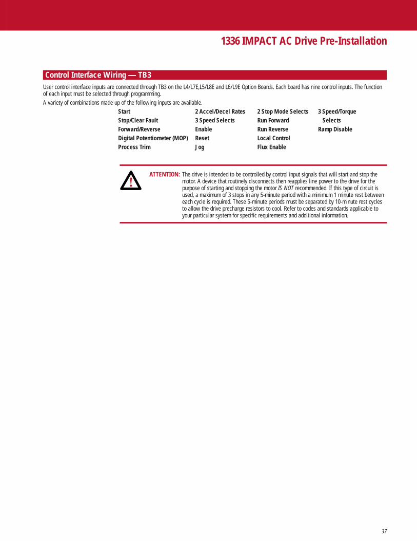
37
1336 IMPACT AC Drive Pre-Installation
Control Interface Wiring — TB3User control interface inputs are connected through TB3 on the L4/L7E,L5/L8E and L6/L9E Option Boards. Each board has nine control inputs. The functionof each input must be selected through programming.A variety of combinations made up of the following inputs are available.
Start 2 Accel/Decel Rates 2 Stop Mode Selects 3 Speed/TorqueStop/Clear Fault 3 Speed Selects Run Forward SelectsForward/Reverse Enable Run Reverse Ramp DisableDigital Potentiometer (MOP) Reset Local ControlProcess Trim Jog Flux Enable
ATTENTION: The drive is intended to be controlled by control input signals that will start and stop the motor. A device that routinely disconnects then reapplies line power to the drive for the purpose of starting and stopping the motor IS NOT recommended. If this type of circuit is used, a maximum of 3 stops in any 5-minute period with a minimum 1 minute rest between each cycle is required. These 5-minute periods must be separated by 10-minute rest cyclesto allow the drive precharge resistors to cool. Refer to codes and standards applicable to your particular system for specific requirements and additional information.
!

38
Control Interface Wiring — TB3
1336 IMPACT AC Drive Pre-Installation
19 20 21 22 23 24 25 26 27 28 29 30 31 32 33 34 35 36
Inpu
t 1
Inpu
t 2 (S
top)
Com
mon
Inpu
t 3
Inpu
t 4
Inpu
t 5
Com
mon
Inpu
t 6
Inpu
t 7
Inpu
t 8
Com
mon
Enab
le
Enco
der B
Enco
der N
OT A
Enco
der N
OT B
Enco
der A
+12V
(200
mA
max
.)
Enco
der C
omm
on
Included on L7E, L8E & L9E Only
Input Mode Selection and Typical TB3 Connections
Input Mode (parameter 102) = 1Factory Default
Status
Not Stop7/Clear Fault3,6
Common
Status
Status
Status
Common
Status
Status
Status
Common
Enable3
19
20
21
22
23
24
25
26
27
28
29
30
Start9
Not Stop7/Clear Faultt3, 6
Common
Rev/Fwd5
Not Ext Fault4, 8
Common
Speed Select 21
Speed Select 11
Common
Enable3
19
20
21
22
23
24
25
26
27
28
29
30
2
Jog
SpeedSelect 31
3
StopType7
SpeedSelect 31
510
DigitalPot UP
Digital Pot Dn
4
2nd/1stAccel
2nd/1stDecel
6
Jog
LocalControl2
Mode17
Process Trim
Ramp
18
Flux Enable
Reset
2710
DigitalPot UP
DigitalPot Dn
Input Mode (parameter 102) = 2-6, 17, 18, and 27Single-Source, Three-Wire Control
Maximum and Minimum Wire Size
The maximum and minimum wire size accepted by TB3 is 2.1 and 0.30 mm2 (14 and 22 AWG). Maximum torque for all terminals is 1.36 N-m (12 lb-in).
1 See Speed Select Table.2 Drive must be stopped to take Local Control. Control by all other adapters is disabled
(except Stop).3 These inputs must be present before drive will start.4 For Common Bus, this becomes Precharge Enable.5 Bit 11 of Logic Options (parameter 17) must be 0 for reverse direction control.
6 For soft faults only. You need to recycle power to the drive or reset to clear hard faults. For hard faults, refer to the troubleshooting chapter.7 To configure the stop type, refer to Logic Options (parameter 17).8 This input must be present before the fault can be cleared and the drive will start. This can be disabled through Fault Select 2 (parameter 22) and Warning Select (parameter 23).9 To configure the start type, refer to Logic Options (parameter 17). Latched (momentary) starts require a stop to stop the drive.10 In Mode 5, the MOP value is not reset to zero when you stop. In Mode 7 the MOP value is reset to zero when you stop.

39
1336 IMPACT AC Drive Pre-Installation
Control Interface Wiring — TB3Input Mode Selection and Typical TB3 Connections
Input Mode (parameter 102) = 7-11 and 19-22Multi-Source, Three-Wire Control
1 See Speed Select Table.2 Drive must be stopped to take Local Control. Control by all other adapters is disabled (except Stop).3 These inputs must be present before drive will start.4 For Common Bus, this becomes Precharge Enable.5 Bit 12 of Logic Options (parameter 17) must be 0 for reverse direction control.6 For soft faults only. You need to recycle power to the drive or reset to clear hard faults. For hard faults, refer to the troubleshooting chapter.7 To configure the stop type, refer to Logic Options (parameter 17).8 This input must be present before the fault can be cleared and the drive will start. This can be disabled through Fault Select 2 (parameter 22) and Warning Select 2
(parameter 23).9 To configure the start type, refer to Logic Options (parameter 17).10 See Speed/Torque Select table.11 Unlatched (maintained) start.12 In Modes 9, 10, and 15, the MOP value is not reset to 0 when you stop. In Modes 28, 29, and 30, the MOP value is reset to 0 when you stop.
Start9
Not Stop7/Clear Faultt3, 6
Common
Not Ext Fault4, 8
Common
Speed Select 11
Common
Enable3
19
20
21
22
23
24
25
26
27
28
29
30
7
Reverse5
Forward5
Jog
SpeedSelect 21
8
Reverse5
Forward5
SpeedSelect 31
SpeedSelect 21
10
Reverse5
Forward5
DigitalPot Up
DigitalPot Dn
9
DigitalPot UpDigitalPot Dn
SpeedSelect 31
SpeedSelect 21
11
1stAccel
2ndAccel
1stDecel
2ndDecel
Mode12
SpeedTorque 310
SpeedTorque 210
SpeedTorque 110
ProcessTrim
19
SpeedTorque 310
SpeedTorque 210
SpeedTorque 110
FluxEnable
21
Reverse5
Forward5
Ramp
Reset
22
SpeedTorque 310
SpeedTorque 210
SpeedTorque 110
SpeedSelect 21
2812
DigitalPot UpDigitalPot Dn
SpeedSelect 31
SpeedSelect 21
2912
Reverse5
Forward5
DigitalPot Up
DigitalPot Dn
Run Forward4, 5, 11
Not Stop7/Clear Fault3, 6
Common
Run Reverse4, 5, 11
Not Ext Fault4, 8
Common
Speed Select 21
Speed Select 11
Common
Enable3
19
20
21
22
23
24
25
26
27
28
29
30
12
LocalControl2
SpeedSelect 31
13
StopType7
SpeedSelect 31
15
DigitalPot UP
Digital Pot Dn
14
2nd/1stAccel
2nd/1stDecel
16
LocalControl2
Digital Pot Dn
Mode23
Process Trim
Ramp
24
Flux Enabble
Reset
25
Process Trim
Ramp
26
Jog
SpeedSelect 31
3012
DigitalPot UP
DigitalPot Dn
Input Mode (parameter 102) = 12-16 and 23-25Single-Source, Two-Wire Control

40
Control & Signal Wiring Frames A1, A2, A3 and A4
1336 IMPACT AC Drive Pre-Installation
J10 (TB10)
+-
Analog Input 2
Shield
4 to 20 mA
Pulse Source
Shield
Shield
Shield
+-
+-
+-
Analog Input 1
J7 (TB7)
1
2
3
6
9
12
4
5
7
8
10
11
Analog Output 2*
Shield
4 to 20 mA*
Shield
Shield
DC PowerSupply*
Analog Output 1*
+-
+-
+-
+10V
Com
-10V
J4 (TB4)
1
2
3
6
9
12
4
5
7
8
10
11
1 2 3 4 5 6 7 8 9 10 11 12
Relay 1Default: At Speed
Supply
Relay 2Default: Enable
(Run)
Relay 3Default: Not Fault
Relay 4Default: Not Warning
(Alarm)
VoltageClearance
TE
* The power supply is for drive input use only.
Terminal TerminalBlock Number(s) Signal
TB4 4, 7, 10 Shield Ground1,2,3 DC Power Supply +/- 10V DC
50 mA per voltage5, 6, 8, 9 0 to +/- 10V DC output: Output Impedance = 100 Ohms;
10 mA maximum11, 12 4-20 mA DC output: Output Impedance = 20 Ohms
TB7 3, 6, 9, 12 Shield Ground 1, 2, 4, 5 0 to +/- 10V DC input: Input Impedance = 20k Ohms7, 8 4-20 mA input Input Impedance = 130 Ohms10, 11 Pulse input for frequency reference +5V DC — Jumper J8 Set to 1-2
+12V DC — Jumper J8 Set to 2-3Scale Factor (Pulse PPR) must be set10 mA minimum
TB10 12 Logic Earth Ground, Shield1, 2, 3 Programmable Contacts4,5,6 Fault Contact Resistive Rating = 115V AC/30V DC,5.0A
Inductive Rating = 115V AC/30V DC, 2.0A7, 8, 9 Alarm Contact Resistive Rating = 115V AC/30V DC, 5.0A
Inductive Rating = 115V AC/30V DC, 2.0A10, 11 Voltage Clearance Provides physical space between the logic
earth ground and other signals on theterminal block.
*Attention: Analog I/O is Differential, Non-isolated I/O. Specifically, connecting the 4-20 mA output of the drive to anon-isolated input of another device may result in a drive component failure.

41
1336 IMPACT AC Drive Pre-Installation
Control & Signal Wiring Frames B, C, D, E, F, G and H
Terminal TerminalBlock Number(s) Signal
TB10 6, 9, 12, 17, 20 Shield Ground
1,2,3 DC Power Supply +/- 10V DC50 mA per voltage
4, 5, 7, 8 0 to +/- 10V DC input: Input Impedance = 20k Ohms
10, 11 4-20 mA Input: Input Impedance = 130 Ohms
13,14 Pulse Input for frequency ref.: +5V DC — Jumper J4 Set to 1-2+12V DC — Jumper J4 Set to 2-3Scale Factor (Pulse PPR) must be set10 mA minimum
15, 16, 18, 19 0 to ±10V DC output Output impedance = 100 Ohms;10 mA maximum
21, 22 4-20 mA DC output Output impedance = 20 Ohms
TB11 10 Logic Earth Ground, Shield
1, 2, 3 Programmable Contacts
4, 5, 6 Fault Contact Resistive Rating = 115V AC/30V DC,5.0AInductive Rating = 115V AC/30V DC, 2.0A
7, 8, 9 Alarm Contact Resistive Rating = 115V AC/30V DC, 5.0AInductive Rating = 115V AC/30V DC, 2.0A
*Attention: Analog I/O is Differential, Non-isolated I/O. Specifically, connecting the 4-20 mA output of the drive to anon-isolated input of another device may result in a drive component failure.
1 2 3 4 5 6 7 8 9 10
Relay 1Default: At Speed
Supply
SH = Shield
Relay 2Default: Enable
(Run)
Relay 3Default: Not Fault
Relay 4Default: Not Warning
(Alarm)
TE
TB11
13 14 15 16 17 18 19 20 21 22
AnalogInput 1
TB10
1 2 3 4 5 6 7 8 9 10 11 12
DC PowerSupply
+10V Com -10V
+ + + + + + +- - - - - - -SH SH SH SH SH
AnalogInput 2
4-20 mAInput
PulseSource
AnalogOutput 1*
AnalogOutput 2*
4-20 mAOutput*
VoltageClearance

42
Customer Supplied Enclosures
1336 IMPACT AC Drive Pre-Installation
Requirements 1336 IMPACT AC drives installed in your enclosures may be mounted within an enclosure or may bemounted to allow the heatsink to extend outside the enclosure. Use the information below incombination with the enclosure manufacturer’s guidelines for sizing.
200-240V DRIVESBase Derate Derate Heat Dissipation
Cat No.10 Amps 1 Curve 2, 3 Drive Watts 2, 3, 9 Heatsink Watts 9 Total Watts 9
AQF05 2.3 Figure 1 13 15 28AQF07 3.0 Figure 1 15 21 36AQF10 4.5 Figure 1 17 32 49AQF15 6.0 Figure 1 21 42 63AQF20 8.0 Figure 1 25 56 81AQF30 12.0 Figure 1 33 72 105AQF50 18.0 Figure 1 42 116 158A007 27.2 NONE 156 486 642A010 33.7 Figure 2 200 721 921A015 48.2 Figure 3 205 819 1024A020 64.5 Figure 4 210 933 1143A025 78.2 Figure 5 215 1110 1325A030 80 NONE 220 1110 1330A040 120.3 Figure 6 361 1708 2069A050 149.2 Figure 7 426 1944 2370A060 180.4 Figure 8 522 2664 3186A075 240 Figure 9 606 2769 3375A100 291.4 Figure 10 755 3700 4455A125 325 Figure 17 902 4100 5002
380-480V DRIVESBase Derate Derate Heat Dissipation
Cat No.10 Amps 1 Curve 2, 3 Drive Watts 2, 3, 9 Heatsink Watts 9 Total Watts 9
BRF05 1.2 Figure 1 12 9 21BRF07 1.7 Figure 1 13 15 28BRF10 2.3 Figure 1 15 20 35BRF15 3.0 Figure 1 16 27 43BRF20 4.0 Figure 1 19 36 55BRF30 6.0 Figure 1 23 54 77BRF50 9.0 Figure 1 29 84 113BRF75 17.5 Figure 1 70 230 300BRF100 25 Figure 1 89 331 420B015 27.2 Figure 11 117 486 603B020 33.7 Figure 2 140 628 768B025 41.8 Figure 12 141 720 861B030 48.2 Figure 3 141 820 961BX040 58.7 Figure 13 175 933 1108B040 64.5 Figure 4 175 933 1108B050 78.2 Figure 5 193 1110 1303BX060 78.2 Figure 5 193 1110 1303B060 96.9 NONE 361 1708 2069B075 120.3 Figure 14 361 1708 2069B100 149.2 Figure 15 426 1944 2370B125 180.4 Figure 16 522 2664 3186BX150 180.4 Figure 16 606 2769 3375B150 240 Figure 9 606 2769 3375B200 292.4 Figure 10 755 3700 4455B250 327.4 Figure 17 902 4100 5002B3005 406.4 NONE 1005 4805 5810BP/BPR3008 357 Figure 18 619 5342 5961B3505 459.2 NONE 1055 5455 6510BP/BPR3508 421 Figure 19 733 6039 6772B4005 505.1 NONE 1295 6175 7470BP/BPR4008 471 Figure 20 793 6329 7122B4505 570.2 NONE 1335 6875 8210BP/BPR4508 527 Figure 21 931 7000 7931B5005 599.2 Figure 22 1400 7800 9200B6005 673.4 Figure 23 1485 8767 10252B700C 850 Figure 37 17006 97006 11400B800C 983 Figure 37 19006 120006 13900
500-600V DRIVESBase Derate Derate Heat Dissipation
Cat No.10 Amps 1 Curve 2, 3 Drive Watts 2, 3, 9 Heatsink Watts 9 Total Watts 9
CWF10 2.5 Figure 24 25 29 54CWF20 4.2 Figure 24 29 57 86CWF30 6 Figure 24 32 87 119CWF50 7.9 Figure 24 35 117 152CWF75 10 Figure 24 91 217 308CWF100 12 Figure 24 103 251 354C015 18.9 NONE 117 360 477C020 23.6 NONE 140 467 607C025 30 NONE 141 492 633C030 34.6 NONE 141 526 667C040 45.1 NONE 175 678 853C050 57.2 NONE 193 899 1092C060 61.6 NONE 193 981 1174C075 85.8 Figure 25 361 1533 1894C100 109.1 Figure 26 426 1978 2504C125 138.6 Figure 27 522 2162 2683C150 159.7 Figure 28 606 2315 2921C200 252.5 Figure 29 755 3065 3820C250 283.6 Figure 30 890 3625 4515C3005 298 NONE 926 5015 5941CX300 298 940 3990 4930C3505 353.6 NONE 1000 5935 6935CP/CPR350 350 Figure 31 580 6125 6705C4005 406.4 Figure 32 1430 7120 8550CP/CPR400 400 Figure 33 711 7000 7711C5005 505.1 Figure 34 1500 8925 10425C6005 599.2 Figure 35 1610 10767 12377C6505 673.4 Figure 36 1700 12000 14000C700C 770 Figure 37 1800 94007 11200C800C 850 Figure 38 2000 113007 13300
1 Base Derate Amps are based on nominalvoltage (240, 480 or 600V). If input voltageexceeds Drive Rating, Drive Output must bederated. Refer to Figure 40.
2 Drive Ambient Temperature Rating is 40°C. If ambient exceeds 40°C, the drive must bederated. Refer to Figures 1-38.
3 Drive Rating is based on altitudes of 1,000m (3,000 ft.) or less. If installed at higheraltitude, drive must be derated. Refer to Figure 39.
4 Not available at time of publication.5 Important: Two (2) 725 CFM fans are
required if an open type drive is mounted ina user supplied enclosure.
6 This is the inverter loss only, common busconfiguration 2kHz PWM.
7 This is the inverter loss only, common busconfiguration 1kHz PWM.
8 Important: 1336E-BPRXXX drives requiretwo (2) fans capable of producing greaterthan 450 CFM. One (1) fan open type driveis mounted in a user-supplied enclosure.
9 Rating is at 4kHz (2kHz for 224-448 kW/300-600 HP, 500-600V). If carrierfrequencies above 4kHz are selected, drive rating must be derated. Refer toFigures 1-40.
10 Due to drive losses, the output voltage tothe motor is affected by the AC inputvoltage to the drive. This reduced motorvoltage may require more motor torque,and therefore current, to achieve ratedmotor horsepower. Though mostapplications do not require full ratedmotor horsepower at full speed, thefollowing information is provided to assist with proper motor/drive selection.A. For 460V motors, operate with a minimum 480V Input AC line voltage.B. Size the motor with the capability tooperate with 8% more current.C. Purchase a motor designed to operate at 440V.Note: For items B and C above, make surethe drive current rating is adequate tosupport the motor.Refer to Figure 41.

43
1336 IMPACT AC Drive Pre-Installation
Derating GuidelinesDrive ratings can be affected by a number of factors. If more than one factor exists, consult Allen-Bradley Company.
Standard Rating for Enclosed Drive in Derating Factor for Enclosed Drive in 40°C Ambient & Open Drive in 50°C Ambient. Ambient between 41°C & 50°C.
% of DriveRated Amps
Carrier Frequency in kHz31 5 7
80%
95%
85%
75%
90%
100%
2 4 6 9 118 10 12
70%
65%
% of DriveRated Amps
Carrier Frequency in kHz31 5 7
80%
95%
85%
75%
90%
100%
2 4 6 9 118 10 12
70%
65%
60%
55%
50%
% of DriveRated Amps
Carrier Frequency in kHz31 5 7
80%
95%
85%
75%
90%
100%
2 4 6 9 118 10 12
70%
65%
60%
% of DriveRated Amps
Carrier Frequency in kHz31 5 7
80%
95%
85%
75%
90%
100%
2 4 6 9 118 10 12
70%
65%
60%
55%
50%
45%
Figure 21336E-A010 and B020
Figure 31336E-A015 and B030
Figure 41336E-A020 and B040
Figure 51336E-A025, B050 and BX060
Carrier Frequency in kHz62 4 10 128
92%
98%
94%
90%
96%
100%
% of DriveRated Amps
Figure 11336E-AQF05-AQF50 and BRF05-BRF100

44
Derating Guidelines
1336 IMPACT AC Drive Pre-Installation
Standard Rating for Enclosed Drive in Derating Factor for Enclosed Drive in 40°C Ambient & Open Drive in 50°C Ambient. Ambient between 41°C & 50°C.
% of DriveRated Amps
Carrier Frequency in kHz2 4 6
92%
98%
94%
90%
96%
100%
Carrier Frequency in kHz
2 4 6
85%90%95%
75%
70%65%
80%
100%
% of DriveRated Amps
Carrier Frequency in kHz
2 4 6
85%90%95%
75%
70%65%
80%
100%
% of DriveRated Amps
60%
% of DriveRated Amps
Carrier Frequency in kHz
31 5
80%
95%
85%
75%
90%
100%
2 4 6
70%
65%
Figure 61336E-A040
Figure 71336E-A050
Figure 81336E-A060
Figure 91336E-A075 and B150

45
1336 IMPACT AC Drive Pre-Installation
Derating GuidelinesStandard Rating for Enclosed Drive in Derating Factor for Enclosed Drive in 40°C Ambient & Open Drive in 50°C Ambient. Ambient between 41°C & 50°C.
% of DriveRated Amps
Carrier Frequency in kHz
31 5
80%
95%
85%
75%
90%
100%
2 4 6
70%
65%
% of DriveRated Amps
Carrier Frequency in kHz
31 5 7
80%
95%
85%
75%
90%
100%
2 4 6 9 118 10 12
70%
65%
% of DriveRated Amps
Carrier Frequency in kHz
31 5 7
80%
95%
85%
75%
90%
100%
2 4 6 9 118 10 12
70%
65%
60%
55%
% of DriveRated Amps
Carrier Frequency in kHz
31 5 7
80%
95%
85%
75%
90%
100%
2 4 6 9 118 10 12
70%
65%
Figure 101336E-A100 and B200
Figure 111336E-B015
Figure 121336E-B025
Figure 131336E-BX040

46
Derating Guidelines
1336 IMPACT AC Drive Pre-Installation
Standard Rating for Enclosed Drive in Derating Factor for Enclosed Drive in 40°C Ambient & Open Drive in 50°C Ambient. Ambient between 41°C & 50°C.
% of DriveRated Amps
Carrier Frequency in kHz2 4 6
92%
98%
94%
90%
96%
100%
Carrier Frequency in kHz
2 4 6
85%90%95%
75%
70%65%
80%
100%
% of DriveRated Amps
Carrier Frequency in kHz
2 4 6
85%90%95%
75%
70%65%
80%
100%
% of DriveRated Amps
% of DriveRated Amps
Carrier Frequency in kHz
31 5
80%
95%
85%
75%
90%
100%
2 4 6
70%
65%
60%
Figure 141336E-B075
Figure 151336E-B100
Figure 161336E-B125 and BX150
Figure 171336E-A125 and B250

47
1336 IMPACT AC Drive Pre-Installation
Derating Guidelines
Standard Rating for Enclosed Drive in Derating Factor for Enclosed Drive in 40°C Ambient & Open Drive in 50°C Ambient. Ambient between 41°C & 50°C.
Carrier Frequency in kHz2 4 6
70%80%90%
50%60%
100%
% of DriveRated Amps
% of DriveRated Amps
Carrier Frequency in kHz2 4 6
60%
90%
70%
50%
80%
100%
% of DriveRated Amps
Carrier Frequency in kHz2 4 6
60%
90%
70%
50%
80%
100%
% of DriveRated Amps
Carrier Frequency in kHz2 4 6
60%
90%
70%
50%
80%
100%
Figure 181336E-BP300 and BPR300
Figure 191336E-BP350 and BPR350
Figure 201336E-BP400 and BPR400
Figure 211336E-BP450 and BPR450

48
Derating Guidelines
1336 IMPACT AC Drive Pre-Installation
Standard Rating for Enclosed Drive in Derating Factor for Enclosed Drive in 40°C Ambient & Open Drive in 50°C Ambient. Ambient between 41°C & 50°C.
% of DriveRated Amps
Carrier Frequency in kHz
31
80%
95%
85%
75%
90%
100%
2 4
70%
65%
% of DriveRated Amps
Carrier Frequency in kHz
31
80%
95%
85%
75%
90%
100%
2 4
70%
65%
% of DriveRated Amps
Carrier Frequency in kHz2 4 6
92%
98%
94%
90%
96%
100%
% of DriveRated Amps
Carrier Frequency in kHz2 4 6
92%
98%
94%
90%
96%
100%
Figure 221336E-B500
Figure 231336E-B600
% of DriveRated Amps
Carrier Frequency in kHz2 8 10
NotRecommended
4 126
92%
98%
94%
90%
96%
100%Figure 241336E-CWF10 through CWF100
Figure 251336E-C075
Figure 261336E-C100

49
1336 IMPACT AC Drive Pre-Installation
Derating GuidelinesStandard Rating for Enclosed Drive in Derating Factor for Enclosed Drive in 40°C Ambient & Open Drive in 50°C Ambient. Ambient between 41°C & 50°C.
Carrier Frequency in kHz
2 4 6
85%90%95%
75%
70%65%
80%
100%
% of DriveRated Amps
% of DriveRated Amps
Carrier Frequency in kHz
31 5
80%
95%
85%
75%
90%
100%
2 4 6
70%
65%
% of DriveRated Amps
Carrier Frequency in kHz
31 5
80%
95%
85%
75%
90%
100%
2 4 6
70%
65%
60%
55%
50%
45%
% of DriveRated Amps
Carrier Frequency in kHz
31 5
80%
95%
85%
75%
90%
100%
2 4 6
70%
65%
60%
55%
50%
45%
40%
Figure 271336E-C125
Figure 281336E-C150
Figure 291336E-C200
Figure 301336E-C250

50
Derating Guidelines
1336 IMPACT AC Drive Pre-Installation
Standard Rating for Enclosed Drive in Derating Factor for Enclosed Drive in 40°C Ambient & Open Drive in 50°C Ambient. Ambient between 41°C & 50°C.
% of DriveRated Amps
Carrier Frequency in kHz
31
80%
95%
85%
75%
90%
100%
2 4
70%
65%
% of DriveRated Amps
Carrier Frequency in kHz
31
80%
95%
85%
75%
90%
100%
2 4
70%
65%
% of DriveRated Amps
Carrier Frequency in kHz
31
80%
95%
85%
75%
90%
100%
2 4
70%
65%
60%
55%
Figure 321336E-C400
% of DriveRated Amps
Carrier Frequency in kHz2 4 6
60%
90%
70%
50%
80%
100%Figure 331336E-CP400
% of DriveRated Amps
Carrier Frequency in kHz2 4 6
60%
90%
70%
50%
80%
100%Figure 311336E-CP350
Figure 341336E-C500
Figure 351336E-C600
% of DriveRated Amps
Carrier Frequency in kHz31
80%
95%
85%
75%
90%
100%
2 4
70%
65%
60%
55%
55%
Figure 361336E-C650

51
1336 IMPACT AC Drive Pre-Installation
Derating GuidelinesStandard Rating for Enclosed Drive in Derating Factor for Enclosed Drive in 40°C Ambient & Open Drive in 50°C Ambient. Ambient between 41°C & 50°C.
% of DriveRated Amps
Altitude
2000(6600)
0
80%
90%
100%
1000(3300)
3000(9900)
4000(13200)
m(ft)
% of DriveRated Amps
Input Voltage
+4%240, 480, or 600VNominal
80%
90%
100%
+2% +6% +8% +10%
0% 10% 20% 30% 40% 50% 60% 70% 80% 90% 100% 105% 110% 115% 120% 125% 130% 135% 140% 145% 150%
20%
40%
60%
80%
100%
120%
0%
Line Derating
Speed
%
Figure 39All Drive Ratings
Figure 41Drive Ratings
Definitions:Calculated HP – Available motor HP outputbased on full voltage/current
Actual HP – Measured HP based onDPI typical drive losses
Actual Motor HPCalculated Motor HP
% of DriveRated Amps
Carrier Frequency in Hz
10000 2000 3000
60%
90%
70%
50%
80%
100%
4000 5000 6000
40%
30%
20%
10%
0%
% of Drive Rating 700 HP% of Drive Rating 800 HP
Figure 371336E-B700C and B800C
% of DriveRated Amps
Carrier Frequency in Hz
10000 2000 3000
60%
90%
70%
50%
80%
100%
4000 5000 6000
40%
30%
20%
10%
0%
% of Drive Rating 700 HP% of Drive Rating 800 HP
Figure 381336E-C700C and C800C
Figure 40Required Only for the following drives:
1336E-A/B/C-025 – 18.5 kW (25 HP) at 8 kHz1336E-A/B/C – 22 kW (30HP) at 6-8 kHz1336E-A/B/C – 45 kW (60 HP) at 6 kHz

52
1336 IMPACT AC Drive Selection Guide
Notes

53
Features
1336 IMPACT AC Drive Selection Guide
ENLANGUAGE
MODULE
(MUST BE SPECIFIED) 1
L6CONTROL
INTERFACE
(OPTIONAL) 2
1336EBULLETIN NO.
1 A Language Module must be specified with each drive.
2 At least one of either a Control Interface, Human Interface or Communication Card Option will be required to make the drive functional. The chosen option(s) may be ordered factoryinstalled or as add-on kits.
B015RATING
(MUST BE SPECIFIED)
AAENCLOSURE
(MUST BE SPECIFIED)
HA1HUMAN
INTERFACE
(OPTIONAL) 2
GM1COMMUNICATION
CARD
(OPTIONAL) 2
Catalog Number Explanation

54
1336 IMPACT AC Drive Selection Guide
Drive Rating 2 Open NEMA Type 1 NEMA Type 4 NEMA Type 12Frame Output Nominal Rated IP00 IP20 IP65 IP54Designation1 Amps HP kW No Enclosure General Purpose 3 Resist Water, Dust Industrial Use
A1 2.3 1/2 0.37 1336E-AQF05-AN 1336E-AQF05-AA/AE 1336E-AQF05-AF 1336E-AQF05-AJ3.0 3/4 0.56 1336E-AQF07-AN 1336E-AQF07-AA/AE 1336E-AQF07-AF 1336E-AQF07-AJ4.5 1 0.75 1336E-AQF10-AN 1336E-AQF10-AA/AE 1336E-AQF10-AF 1336E-AQF10-AJ
A2 6.0 1-1/2 1.2 1336E-AQF15-AN 1336E-AQF15-AA/AE 1336E-AQF15-AF 1336E-AQF15-AJ8.0 2 1.5 1336E-AQF20-AN 1336E-AQF20-AA/AE 1336E-AQF20-AF 1336E-AQF20-AJ
A3 12.0 3 2.2 1336E-AQF30-AN 1336E-AQF30-AA/AE 1336E-AQF30-AF 1336E-AQF30-AJ18.0 5 3.7 1336E-AQF50-AN 1336E-AQF50-AA/AE 1336E-AQF50-AF 1336E-AQF50-AJ
B1 27.2 7.5 5.5 1336E-A007-AN 1336E-A007-AA/AE 1336E-A007-AF 1336E-A007-AJ
B2 33.7 10 7.5 1336E-A010-AN 1336E-A010-AA/AE 1336E-A010-AF 1336E-A010-AJ48.2 15 11 1336E-A015-AN 1336E-A015-AA/AE 1336E-A015-AF 1336E-A015-AJ
C 64.5 20 15 1336E-A020-AN 1336E-A020-AA/AE 1336E-A020-AF 1336E-A020-AJ78.2 25 18.5 1336E-A025-AN 1336E-A025-AA/AE 1336E-A025-AF 1336E-A025-AJ80.0 30 22 1336E-A030-AN 1336E-A030-AA/AE 1336E-A030-AF 1336E-A030-AJ
D 120.3 40 30 1336E-A040-AN 1336E-A040-AA/AE 4 1336E-A040C-AJ149.2 50 37 1336E-A050-AN 1336E-A050-AA/AE 4 1336E-A050C-AJ180.4 60 45 1336E-A060-AN 1336E-A060 AA/AE 4 1336E-A060C-AJ
E 240.0 75 56 1336E-A075-AN 1336E-A075-AA/AE 4 1336E-A075C-AJ291.4 100 75 1336E-A100-AN 1336E-A100-AA/AE 4 1336E-A100C-AJ327.4 125 93 1336E-A125-AN 1336E-A125-AA/AE 4 1336E-A125C-AJ
Drive Codes and Enclosures
Drive Rating 2 Open NEMA Type 1 NEMA Type 1 NEMA Type 4 NEMA Type 12Frame Output Nominal Rated IP00 IP20 IP20 IP65 IP54Designation1 Amps HP kW No Enclosure General Purpose CE Conformance Resist Water, Dust Industrial Use
A1 1.2 1/2 0.37 1336E-BRF05-AN 1336E-BRF05-AA 1336E-BRF05-AE 1336E-BRF05-AF 1336E-BRF05-AJ1.7 3/4 0.56 1336E-BRF07-AN 1336E-BRF07-AA 1336E-BRF07-AE 1336E-BRF07-AF 1336E-BRF07-AJ2.3 1 0.75 1336E-BRF10-AN 1336E-BRF10-AA 1336E-BRF10-AE 1336E-BRF10-AF 1336E-BRF10-AJ3.0 1-1/2 1.2 1336E-BRF15-AN 1336E-BRF15-AA 1336E-BRF15-AE 1336E-BRF15-AF 1336E-BRF15-AJ
A2 4.0 2 1.5 1336E-BRF20-AN 1336E-BRF20-AA 1336E-BRF20-AE 1336E-BRF20-AF 1336E-BRF20-AJ6.0 3 2.2 1336E-BRF30-AN 1336E-BRF30-AA 1336E-BRF30-AE 1336E-BRF30-AF 1336E-BRF30-AJ
A3 9.0 5 3.7 1336E-BRF50-AN 1336E-BRF50-AA 1336E-BRF50-AE 1336E-BRF50-AF 1336E-BRF50-AJ
A4 13.9 7.5 5.5 1336E-BRF75-AN 1336E-BRF75-AA 1336E-BRF75-AE 1336E-BRF75-AF 1336E-BRF75-AJ24 10 7.5 1336E-BRF100-AN 1336E-BRF100-AA 1336E-BRF100-AE 1336E-BRF100-AF 1336E-BRF100-AJ
B1 27.2 15 11 1336E-B015-AN 1336E-B015-AA 1336E-B015-AE 1336E-B015-AF 1336E-B015-AJ
B2 33.7 20 15 1336E-B020-AN 1336E-B020-AA 1336E-B020-AE 1336E-B020-AF 1336E-B020-AJ41.8 25 18.5 1336E-B025-AN 1336E-B025-AA 1336E-B025-AE 1336E-B025-AF 1336E-B025-AJ48.2 30 22 1336E-B030-AN 1336E-B030-AA 1336E-B030-AE 1336E-B030-AF 1336E-B030-AJ
C 58.7 40 30 1336E-BX040-AN 1336E-BX040-AA 1336E-BX040-AE 1336E-BX040-AF 1336E-BX040-AJ64.5 40 30 1336E-B040-AN 1336E-B040-AA 1336E-B040-AE 1336E-B040-AF 1336E-B040-AJ78.2 50 37 1336E-B050-AN 1336E-B050-AA 1336E-B050-AE 1336E-B050-AF 1336E-B050-AJ78.2 60 45 1336E-BX060-AN5 1336E-BX060-AA 1336E-BX060-AE 1336E-BX060-AF5 1336E-BX060-AJ5
D 96.9 60 45 1336E-B060-AN 1336E-B060-AA 1336E-B060-AE 4 1336E-B060C-AJ120.3 75 56 1336E-B075-AN 1336E-B075-AA 1336E-B075-AE 4 1336E-B075C-AJ149.2 100 75 1336E-B100-AN 1336E-B100-AA 1336E-B100-AE 4 1336E-B100C-AJ180.4 125 93 1336E-B125-AN 1336E-B125-AA 1336E-B125-AE 4 1336E-B125C-AJ180.4 150 112 1336E-BX150-AN 1336E-BX150-AA 1336E-BX150-AE 4 1336E-BX150C-AJ
1 Refer to Pages 15-22 for frame dimensions.2 Drive rating is based on nominal voltage and carrier frequency at altitudes of 1000 meters or less. Refer to Derating Guidelines on Pages 43 to 51 for derating information.3 Conformance to CE also requires an EMC Filter and installation per the 1336 IMPACT User Manual, publication 1336 IMPACT-5.0.4 Not available in this rating.5 480 volts only.
200-240V
380-460V

55
Features
Drive Codes and Enclosures
1336 IMPACT AC Drive Selection Guide
Drive Rating 2 Open NEMA Type 1 NEMA Type 4 NEMA Type 12Frame Output Nominal Rated IP00 IP20 IP65 IP54Designation1 Amps HP kW No Enclosure General Purpose Resist Water, Dust Industrial Use
A4 2.5 1 0.75 1336E-CWF10-AN 1336E-CWF10-AA 1336E-CWF10-AF 1336E-CWF10-AJ4.2 2 1.5 1336E-CWF20-AN 1336E-CWF20-AA 1336E-CWF20-AF 1336E-CWF20-AJ6.0 3 2.2 1336E-CWF30-AN 1336E-CWF30-AA 1336E-CWF30-AF 1336E-CWF30-AJ7.9 5 3.7 1336E-CWF50-AN 1336E-CWF50-AA 1336E-CWF50-AF 1336E-CWF50-AJ9.9 7.5 5.5 1336E-CWF75-AN 1336E-CWF75-AA 1336E-CWF75-AF 1336E-CWF75-AJ
12.0 10 7.5 1336E-CWF100-AN 1336E-CWF100-AA 1336E-CWF100-AF 1336E-CWF100-AJB 18.9 15 11 1336E-C015-AN 1336E-C015-AA 1336E-C015-AF 1336E-C015-AJ
23.6 20 15 1336E-C020-AN 1336E-C020-AA 1336E-C020-AF 1336E-C020-AJC 30.0 25 18.5 1336E-C025-AN 1336E-C025-AA 1336E-C025-AF 1336E-C025-AJ
34.6 30 22 1336E-C030-AN 1336E-C030-AA 1336E-C030-AF 1336E-C030-AJ45.1 40 30 1336E-C040-AN 1336E-C040-AA 1336E-C040-AF 1336E-C040-AJ57.2 50 37 1336E-C050-AN 1336E-C050-AA 1336E-C050-AF 1336E-C050-AJ61.6 60 45 1336E-C060-AN 1336E-C060-AA 1336E-C060-AF 1336E-C060-AJ
D 85.8 75 56 1336E-C075-AN 1336E-C075-AA 4 1336E-C075C-AJ109.1 100 75 1336E-C100-AN 1336E-C100-AA 4 1336E-C100C-AJ138.6 125 93 1336E-C125-AN 1336E-C125-AA 4 1336E-C125C-AJ
E 159.7 150 112 1336E-C150-AN 1336E-C150-AA 4 1336E-C150C-AJ252.5 200 149 1336E-C200-AN 1336E-C200-AA 4 1336E-C200C-AJ283.6 250 187 1336E-C250-AN 1336E-C250-AA 4 1336E-C250C-AJ
F 350.0 350 261 1336E-CP350-AN 1336E-CP350-AA 4 41336E-CPR350-AN – 4 4
400.0 400 298 1336E-CP400-AN 1336E-CP400-AA 4 41336E-CPR400-AN – 4 4
G 298.0 300 224 1336E-C300-AN 1336E-C300A-AA 4 1336E-C300C-AJ353.6 350 261 1336E-C350-AN 1336E-C350A-AA 4 1336E-C350C-AJ406.4 400 298 1336E-C400-AN 1336E-C400A-AA 4 1336E-C400C-AJ459.2 450 336 1336E-C450-AN 1336E-C450A-AA 4 4505.1 500 373 1336E-C500-AN 1336E-C500A-AA 4 4599.2 600 448 1336E-C600-AN 1336E-C600A-AA 4 4673.4 650 485 1336E-C650-AN 1336E-C650A-AA 4 4
H1 770.0 700 522 4 1336E-C700C-AA 4 4(6 pulse) 800.0 800 597 4 1336E-C800C-AA 4 4
1 Refer to Pages 15-22 for frame dimensions.2 Drive rating is based on nominal voltage and carrier frequency at altitudes of 1000
meters or less. Refer to Derating Guidelines on Pages 43 to 51 for derating information.3 Conformance to CE also requires an EMC Filter and installation per the 1336 IMPACT
User Manual, publication 1336 IMPACT-5.0.
4 Not available in this rating.5 Option -CM (common mode choke) or Option -NCM (no common mode choke) must be
specified with each F frame drive.
500-600V
380-460V
Drive Rating 2 Open NEMA Type 1 NEMA Type 1 NEMA Type 4 NEMA Type 12Frame Output Nominal Rated IP00 IP20 IP20 IP65 IP54Designation1 Amps HP kW No Enclosure General Purpose CE Conformance 3 Resist Water, Dust Industrial Use
E 240.0 150 112 1336E-B150-AN 1336E-B150-AA 1336E-B150-AE 4 1336E-B150C-AJ291.4 200 149 1336E-B200-AN 1336E-B200-AA 1336E-B200-AE 4 1336E-B200C-AJ327.4 250 187 1336E-B250-AN 1336E-B250-AA 1336E-B250-AE 4 1336E-B250C-AJ
F5 406.4 300 224 1336E-BP300-AN 1336E-BP300-AA – 4 41336E-BPR300-AN – 1336E-BPR300A-AE
459.2 350 261 1336E-BP350-AN 1336E-BP350-AA – 4 41336E-BPR350-AN – 1336E-BPR350-A-AE
481.0 400 298 1336E-BP400-AN 1336E-BP400-AA – 4 41336E-BPR400-AN – 1336E-BPR400A-AE
531.7 450 336 1336E-BP450-AN 1336E-BP450-AA 4 41336E-BPR450-AN – 1336E-BPR450A-AE
G 406.4 300 224 1336E-B300-AN 1336E-B300A-AA 1336E-B300A-AE 4 1336E-B300C-AJ459.2 350 261 1336E-B350-AN 1336E-B350A-AA 1336E-B350A-AE 4 1336E-B350C-AJ505.1 400 298 1336E-B400-AN 1336E-B400A-AA 1336E-B400A-AE 4 1336E-B400C-AJ570.2 450 336 1336E-B450-AN 1336E-B450A-AA 1336E-B450A-AE 4 4599.2 500 373 1336E-B500-AN 1336E-B500A-AA 1336E-B500A-AE 4 4673.4 600 448 1336E-B600-AN 1336E-B600A-AA 1336E-B600A-AE 4 4
H1 850.0 700 522 4 1336E-B700C-AA 4 4 4(6 pulse) 983.0 800 597 4 1336E-B800C-AA 4 4 4

56
Features
1336 IMPACT AC Drive Selection Guide
Control Interface Kits (Factory Installed)
Human Interface Module Kits (Factory Installed)
Communications Options (Factory Installed)
Common Mode Choke for F Frame Drives Only (Factory Installed — Select One)
Control Interface Kits (For Customer Installation)
Gasket and Enclosure Kits (For Customer Installation)
Description Used With . . . Option Code (Installed)Control Interface ALL 1336E Drives
Contact Closure – L4+24V AC/DC – L5115V AC – L6
Control Interface with Encoder Feedback All 1336E DrivesContact Closure – L7E+24V AC/DC – L8E115V AC – L9E
Description Used With . . . Option Code (Installed)Human Interface Module, NEMA Type 1 IP00 (Open) and
Blank - No Functionality IP20 (NEMA Type 1) -HABProgrammer Only Drives -HAPProgrammer/Controller with Analog Pot -HA1Programmer/Controller with Digital Pot -HA2
Human Interface Module, NEMA Type 12 IP66 or IP54Programmer Only (NEMA Type 12) -HJP1Programmer/Controller with Digital Pot Drives -HJ21
Description Used With . . . Option Code (Installed)Control Interface All 1336E Drives
Contact Closure 1336-L424V AC/DC 1336-L5115V AC 1336-L6
Control Interface with Encoder Feedback All 1336E DrivesContact Closure 1336-L7E24V AC/DC 1336-L8E115V AC 1336-L9E
Description Used With . . . Option CodeSingle Point RIO Frame B, C, D, E, F, G & H -GM12RS232/422/485, DF1 & DH485 Protocol -GM22DeviceNet -GM52Enhanced DeviceNet -GM62
Description Used With . . . Option CodeNo Common Mode Choke All F Frame Drives -NCMInternal Common Mode Choke – Installed -CMInternal Common Mode Choke – Installed All G Frame Drives -CM
Used with Frame Catalog Number (Loose Kit)Description3 Designation3 200-240V 380-480V 500-600VGasket Kits A1, A2, A3 1336-RF3 1336-RF3 –For mounting 1336E Drives A4 – 1336-RF2 1336-RF2in User Supplied IP54 or 65 B 1336-RF4 1336-RF4 1336-RF4(NEMA Type 12 or 4) Enclosures C 1336-RF5 1336-RF5 1336-RF5Gasket Kits D 1336-RF6 1336-RF6 1336-RF6For mounting 1336E Drives E 1336-RF7 1336-RF7 1336-RF7in User Supplied IP54(NEMA Type 12) EnclosuresEnclosure Kits A1, A2, A3 1336E-AA3 1336E-AA3 –IP20 (NEMA Type 1) A4 – 1336E-AA2 1336E-AA2
B 1336E-AA4 1336E-AA4 1336E-AA4C 1336E-AA5 1336E-AA5 1336E-AA5D 1336E-AA6 1336E-AA6 1336E-AA6E 1336E-AA7 1336E-AA7 1336E-AA7
Enclosure Kits A1, A2, A3 1336E-AE3 1336E-AE3 –IP20 (NEMA Type 1) A4 1336E-AE2 1336E-AE2 –for CE Conformance B 1336E-AE4 1336E-AE4 1336E-AE45
C 1336E-AE5 1336E-AE5 1336E-AE55D 1336E-AE6 1336E-AE6 1336E-AE65E 1336E-AE7 1336E-AE7 1336E-AE75
Enclosure Kits A1, A2, A3 1336E-AJA3 1336E-AJA3 –IP54 (NEMA Type 12) A4 – 1336E-AJA4B 1336E-AJA4C
B1 1336E-AJB1A 1336E-AJB1B 1336E-AJB1CB2 1336E-AJB2A 1336E-AJB2B 1336E-AJB2CC 1336E-AJCA 1336E-AJCB 1336E-AJCC
Enclosure Kits4 A1, A2, A3 1336E-AFA3 1336E-AFA3 –IP65 (NEMA Type 4) A4 – 1336E-AFA4B 1336E-AFA4C
B1 1336E-AFB1A 1336E-AFB1B 1336E-AFB1CB2 1336E-AFB2A 1336E-AFB2B 1336E-AFB2CC 1336E-AFCA 1336E-AFCB 1336E-AFCC
1 This option may be used on an IP65 or IP66 rated enclosure to meet watertight indoor applications.2 Requires a Communication Option Cable (1202-C03/C10/C30/C90) to be functional. These units are not acceptable for NEMA Type 4 door mounting or UL Type 4x outdoor duty.3 Refer to Page 14 for frame designations.4 Use of a door mounted Human Interface Module on these enclosures will void the NEMA Type 4 rating.

57
Features
Dynamic Brake Kits (For Customer Installation)
1336 IMPACT AC Drive Selection Guide
Description Used With . . . Catalog Number(Loose Kit)
Remote Mounted With Integral 115V AC All 1336E Drive RatingsPower Supply
Single Point RIO 1203-GD12RS232/422/485, DF1 and DH485 Protocol 1203-GD22
Remote Mounted, For Use With 24V DC All 1336E Drive RatingsPower Supply
Single Point RIO 1203-GK12RS232/422/485, DF1 and DH485 Protocol 1203-GK22DeviceNet 1203-GK52
Communication Option Cable Kits All CommunicationsOptions Listed Above
One-Third Meter Length 1202-C03One Meter Length 1202-C10Three Meter Length 1202-C30Nine Meter Length 1202-C90
SCANport Expander Module All Drive RatingsOne to Two 1203-SG2One to Four 1203-SG4
Drive Mounted and Drive Powered 1336E Drives –Single Point RIO Frames B, C, D, E, 1336-GM1RS232/422/485, DF1 and DH485 Protocol F and G 1336-GM2DeviceNet 1336-GM5
Flex I/O TerminalFlex I/O Terminal Base All Drive Ratings 1203-FB1 3Flex I/O Module All Drive Ratings 1203-FM1 2, 3
SLC Communication Module All Drive Ratings 1203-SM1
1 Multiple kits may be utilized together to obtain higher HP ratings. Refer to Publication1336-5.64 or 1336-5.65 for guidance.
2 Requires a Communication Option Cable (1202-C03/C10/C30/C90) to be functional.
3 Each Flex I/O SCANport requires (1)1203-FB1 and (1)1203-FM1.4 Limited to motor cable lengths of 61 meters (200 feet).
Description1 Used With . . . Catalog Number
IP65 (NEMA Type 4x) 0.75-3.7 KW (1-5 HP), 1204-TFA14Connection Cable Included 460V Drives
2.2-448 KW (3-600 HP), 1204-TFB2460 & 575V Drives
Used Catalog Number Catalog NumberDescription1 With . . . Complete Brake Brake Chopper
for 200-240V AC Drives 0.37-3.7 kW (0.5-5 HP) 1336-MOD-KA005 1336-WA0185.5-7.5 kW (7.5-10 HP) 1336-MOD-KA010 1336-WA01811-22 kW (15-30 HP) NA 1336-WA07030-56 kW (40-75 HP) NA 1336-WA115
for 380-480V AC Drives 0.37-3.7 kW (0.5-5 HP) 1336-MOD-KB005 1336-WB0095.5-7.5 kW (7.5-10 HP) 1336-MOD-KB010 1336-WB00911-37 kW (15-50 HP) 1336-MOD-KB050 1336-WB03545-149 kW (60-200 HP) NA 1336-WB110
for 500-600V AC Drives 0.37-3.7 kW (0.5-5 HP) 1336-MOD-KC005 1336-WC0095.5-7.5 kW (7.5-10 HP) 1336-MOD-KC010 1336-WC00911-30 kW (15-40 HP) 1336-MOD-KC050 1336-WC03537-149 kW (50-200 HP) NA 1336-WC085
Terminator Kits (For Customer Installation)
Description Used With . . . Option CodeEnglish All 1336E Drives -ENFrench -FRGerman -DEItalian -ITPortuguese -PTSpanish -ES
Language Group (Factory Installed)
Description Used With . . . Option CodeEnglish/English All 1336E Drives 1336E-EN31English/French with 3.xx firmware 1336E-FR31English/German 1336E-DE31English/Italian 1336E-IT31English/Portuguese 1336E-PT31English/Spanish 1336E-ES31
Language Group (User Installed)
Communication Option Kits (For Customer Installation)

58
Features
1336 IMPACT AC Drive Selection Guide
Human Interface Module Kits (For Customer Installation)
Description Used With Catalog Number(Loose Kit)
NEMA Type 1 (Normal) All Open Chassis andNEMA Type 1 1336E Drives
Blank-No Functionality 1201-HABProgrammer Only 1201-HAPProgrammer/Controller with Analog Pot 1201-HA1Programmer/Controller with Digital Pot 1201-HA2
NEMA Type 4 All NEMA Type 4 & 12 1336E Drives
Programmer Only 1201-HFP1
Programmer/Controller with Digital Pot 1201-HF21
Door Mount Bezel Kit, NEMA Type 1 Customer Supplied 1201-DMANEMA Type 1 Enclosures andNormal NEMA Type 1 HIM Modules
Option Cable Kits All Human Interface Modules NotMounted on the Drive Chassis
(Connects to HIM Cradle Port)One-Third Meter Length 1202-H03One Meter Length 1202-H10Three Meter Length 1202-H30Nine Meter Length 1202-H90
(Connects to Communication Port)One-Third Meter Length 1202-C03One Meter Length 1202-C10Three Meter Length 1202-C30Nine Meter Length 1202-C90
1 Requires a Communication Option Cable (1202-C03/C10/C30/C90) to be functional.

59
Features
1336 IMPACT AC Drive Selection Guide
Description1 Used With . . . Catalog Number Open Style, 1A Communication and Signal Type Cables 1321-M001Open Style, 9A All Drives Rated: 1321-M009(with Terminal Block) 230V, 0.37-1.5 kW (0.5-2 HP)
480V, 0.37-3.7 kW (0.5-5 HP)Open Style, 48A All Drives Rated: 1321-M048
230V, 2.2-11 kW (3-15 HP)480V, 5.5-22 kW (7.5-30 HP)600V, 0.75-30 kW (1-40 HP)
Open Style, 180A All Drives Rated: 1321-M180230V, 15-45 kW (20-60 HP)480V, 30-112 kW (40-X150 HP)600V, 37-112 kW (50-150 HP)
Open Style, 670A All Drives Rated: 1321-M670230V, 56-93 kW (75-125 HP)480V, 112-448 kW (150-600 HP)600V, 149-448 kW (200-600 HP)
Frame Catalog NumberDescription Voltage Horsepower Designation (Loose Kit)
Lug Kit, Includes:(3) Input Lugs 240V AC/310 V DC 40 HP D 1336-LUG-AQ040(3) Output Lugs 50 HP D 1336-LUG-AQ050(2) DC Bus Lugs 60 HP D 1336-LUG-AQ060(2) TE Ground Lugs 75 HP E 1336-LUG-AQ075(1) PE Ground Lug 100 HP E 1336-LUG-AQ100
480V AC/620V DC 60 HP D 1336-LUG-BR06075 HP D 1336-LUG-BR075100 HP D 1336-LUG-BR100125 HP D 1336-LUG-BR125X150 HP D 1336-LUG-BRX150150 HP D 1336-LUG-BR150200 HP E 1336-LUG-BR200250 HP E 1336-LUG-BR250
600V AC/775V DC 60 HP D 1336-LUG-CW06075 HP D 1336-LUG-CW075100 HP D 1336-LUG-CW100125 HP D 1336-LUG-CW125150 HP E 1336-LUG-CW150200 HP E 1336-LUG-CW200250 HP E 1336-LUG-CW250
1 Input Reactor Only.
Input or Output Line Reactor – 3% Impedance Input or Output Line Reactor – 5% Impedance
IP00 (Open Style) IP11 (NEMA Type 1) IP00 (Open Style) IP11 (NEMA Type 1)
Catalog Catalog Catalog CatalogNumber Number Number Number
0.37 (0.50) 1321-3R2-D 1321-3RA2-D 1321-3R2-A 1321-3RA2-A0.56 (0.75) 1321-3R4-A 1321-3RA4-A 1321-3R4-B 1321-3RA4-B0.75 (1) 1321-3R4-A 1321-3RA4-A 1321-3R4-B 1321-3RA4-B1.2 (1.5) 1321-3R8-A 1321-3RA8-A 1321-3R8-B 1321-3RA8-B1.5 (2) 1321-3R8-A 1321-3RA8-A 1321-3R8-B 1321-3RA8-B2.2 (3) 1321-3R12-A 1321-3RA12-A 1321-3R12-B 1321-3RA12-B3.7 (5) 1321-3R18-A 1321-3RA18-A 1321-3R18-B 1321-3RA18-B5.5 (7.5) 1321-3R25-A 1321-3RA25-A 1321-3R25-B 1321-3RA25-B7.5 (10) 1321-3R35-A 1321-3RA35-A 1321-3R35-B 1321-3RA35-B11 (15) 1321-3R45-A 1321-3RA45-A 1321-3R45-B 1321-3RA45-B15 (20)1 1321-3R55-A1 1321-3RA55-A1 1321-3R55-B1 1321-3RA55-B115 (20) 1321-3R80-A 1321-3RA80-A 1321-3R80-B 1321-3RA80-B18.5 (25) 1321-3R80-A 1321-3RA80-A 1321-3R80-B 1321-3RA80-B22 (30) 1321-3R80-A 1321-3RA80-A 1321-3R80-B 1321-3RA80-B30 (40) 1321-3R130-A 1321-3RA130-A 1321-3R130-B 1321-3RA130-B37 (50) 1321-3R160-A 1321-3RA160-A 1321-3R160-B 1321-3RA160-B45 (60) 1321-3R200-A 1321-3RA200-A 1321-3R200-B 1321-3RA200-B56 (75) 1321-3RB250-A 1321-3RA250-A 1321-3RB250-B 1321-3RA250-B75 (100) 1321-3RB320-A 1321-3RA320-A 1321-3RB320-B 1321-3RA320-B93 (125) 1321-3RB320-A 1321-3RA320-A 1321-3RB320-B 1321-3RA320-B
Line reactors 200-230V AC InputLINE REACTORS and ISOLATION TRANSFORMERS (FOR REMOTE CUSTOMER INSTALLATION)
SPECIFICATIONS:LINE REACTORS – Iron core, 3%impedance, 600V, Class H insulation,115°C rise, copper wound, 50.60 Hz.,terminal blocks (80A and below), copperbox lugs (160A and above), UL, CSA.
ISOLATION TRANSFORMERS:230V/230V or 460V/460V Deltaprimary/Wye secondary. Class Hinsulation, 150°C rise, aluminum wound,60 Hz ±5% taps, (1) NC thermostat percoil, UL, CSA.
DriveRatings kW (HP)
Lug Kits (For Customer Installation)
Common Mode Choke Kits (For Customer Installation)
Line Reactor Kits (For Customer Installation)

60
Features
1336 IMPACT AC Drive Selection Guide
Line Reactor Kits (For Remote Customer Installation)
LINE REACTORS and ISOLATION TRANSFORMERS (FOR REMOTE CUSTOMER INSTALLATION)
SPECIFICATIONS:LINE REACTORS – Iron core, 3%impedance, 600V, Class H insulation,115°C rise, copper wound, 50.60 Hz.,terminal blocks (80A and below), copperbox lugs (160A and above), UL, CSA.
ISOLATION TRANSFORMERS:230V/230V or 460V/460V Deltaprimary/Wye secondary. Class Hinsulation, 150°C rise, aluminum wound,60 Hz ±5% taps, (1) NC thermostat percoil, UL, CSA.
1 Input Reactor on G Frame Drives Only.
Input or Output Line Reactor – 3% Impedance Input or Output Line Reactor – 5% ImpedanceIP00 (Open Style) IP10 (NEMA Type 1) IP00 (Open Style) IP10 (NEMA Type 1)Catalog Catalog Catalog CatalogNumber Number Number Number
0.37 (0.50) 1321-3R2-B 1321-3RA2-B 1321-3R2-B 1321-3RA2-B0.56 (0.75) 1321-3R2-B 1321-3RA2-B 1321-3R2-B 1321-3RA2-B0.75 (1) 1321-3R2-A 1321-3RA2-A 1321-3R2-B 1321-3RA2-B1.2 (1.5) 1321-3R4-B 1321-3RA4-B 1321-3R4-C 1321-3RA4-C1.5 (2) 1321-3R4-B 1321-3RA4-B 1321-3R4-C 1321-3RA4-C2.2 (3) 1321-3R8-B 1321-3RA8-B 1321-3R8-C 1321-3RA8-C3.7 (5) 1321-3R8-B 1321-3RA8-B 1321-3R8-C 1321-3RA8-C5.5 (7.5) 1321-3R12-B 1321-3RA12-B 1321-3R12-C 1321-3RA12-C7.5 (10) 1321-3R18-B 1321-3RA18-B 1321-3R18-C 1321-3RA18-C11 (15) 1321-3R25-B 1321-3RA25-B 1321-3R25-C 1321-3RA25-C15 (20) 1321-3R35-B 1321-3RA35-B 1321-3R35-C 1321-3RA35-C18.5 (25) 1321-3R35-B 1321-3RA35-B 1321-3R35-C 1321-3RA35-C22 (30) 1321-3R45-B 1321-3RA45-B 1321-3R45-C 1321-3RA45-C30 (40) 1321-3R55-B 1321-3RA55-B 1321-3R55-C 1321-3RA55-C37 (50) 1321-3R80-B 1321-3RA80-B 1321-3R80-C 1321-3RA80-C45 (60) 1321-3R80-B 1321-3RA80-B 1321-3R80-C 1321-3RA80-C56 (75) 1321-3R100-B 1321-3RA100-B 1321-3R100-C 1321-3RA100-C75 (100) 1321-3R130-B 1321-3RA130-B 1321-3R130-C 1321-3RA130-C95 (125) 1321-3R160-B 1321-3RA160-B 1321-3R160-C 1321-3RA160-C112 (150) 1321-3R200-B 1321-3RA200-B 1321-3R200-C 1321-3RA200-C149 (200) 1321-3RB250-B 1321-3RA250-B 1321-3RB250-C 1321-3RA250-C187 (250) 1321-3RB320-B 1321-3RA320-B 1321-3RB320-C 1321-3RA320-C224 (300) 1321-3RB400-B 1321-3RA400-B 1321-3RB400-C 1321-3RA400-C261 (350)1 1321-3RB400-B 1321-3RA400-B 1321-3RB400-C 1321-3RA400-C261 (350) 1321-3R500-B 1321-3RA500-B 1321-3R500-C 1321-3RA500-C298 (400) 1321-3R500-B 1321-3RA500-B 1321-3R500-C 1321-3RA500-C336 (450)1 1321-3R500-B 1321-3RA500-B 1321-3R500-C 1321-3RA500-C336 (450) 1321-3R600-B 1321-3RA600-B 1321-3R600-C 1321-3RA600-C373 (500) 1321-3R600-B 1321-3RA600-B 1321-3R600-C 1321-3RA600-C448 (600) 1321-3R750-B 1321-3RA750-B 1321-3R750-C 1321-3RA750-C522 (700) 1321-3R850-B 1321-3RA850-B 1321-3R850-C 1321-3RA850-C597 (800) 1321-3R1000-B 1321-3RA1000-B 1321-3R1000-C 1321-3RA1000-C
LINE REACTORS 380-480V AC INPUT
DriveRatings kW (HP)
Input or Output Line Reactor – 3% Impedance Input or Output Line Reactor – 5% ImpedanceIP00 (Open Style) IP11 (NEMA Type 1) IP00 (Open Style) IP11 (NEMA Type 1)Catalog Catalog Catalog CatalogNumber Number Number Number
0.75 (1) 1321-3R4-C 1321-3RA4-C 1321-3R4-D 1321-3RA4-D1.5 (2) 1321-3R4-C 1321-3RA4-C 1321-3R4-D 1321-3RA4-D2.2 (3) 1321-3R8-C 1321-3RA8-C 1321-3R8-D 1321-3RA8-D3.7 (5) 1321-3R8-B 1321-3RA8-B 1321-3R8-C 1321-3RA8-C5.5 (7.5) 1321-3R8-B 1321-3RA8-B 1321-3R8-C 1321-3RA8-C7.5 (10) 1321-3R12-B 1321-3RA12-B 1321-3R12-C 1321-3RA12-C11 (15) 1321-3R18-B 1321-3RA18-B 1321-3R18-C 1321-3RA18-C15 (20) 1321-3R25-B 1321-3RA25-B 1321-3R25-C 1321-3RA25-C18.5 (25) 1321-3R25-B 1321-3RA25-B 1321-3R25-C 1321-3RA25-C22 (30) 1321-3R35-B 1321-3RA35-B 1321-3R35-C 1321-3RA35-C30 (40) 1321-3R45-B 1321-3RA45-B 1321-3R45-C 1321-3RA45-C37 (50) 1321-3R55-B 1321-3RA55-B 1321-3R55-C 1321-3RA55-C45 (60) 1321-3R80-B 1321-3RA80-B 1321-3R80-C 1321-3RA80-C56 (75) 1321-3R80-B 1321-3RA80-B 1321-3R80-C 1321-3RA80-C75 (100) 1321-3R100-B 1321-3RA100-B 1321-3R100-C 1321-3RA100-C95 (125) 1321-3R130-B 1321-3RA130-B 1321-3R130-C 1321-3RA130-C112 (150) 1321-3R160-B 1321-3RA160-B 1321-3R160-C 1321-3RA160-C149 (200) 1321-3R200-B 1321-3RA200-B 1321-3R200-C 1321-3RA200-C187 (250) 1321-3RB250-B 1321-3RA250-B 1321-3RB250-C 1321-3RA250-C224 (300) 1321-3RB320-B 1321-3RA320-B 1321-3RB320-C 1321-3RA320-C261 (350) 1321-3RB400-B 1321-3RA400-B 1321-3RB400-C 1321-3RA400-C298 (400) 1321-3RB400-B 1321-3RA400-B 1321-3RB400-C 1321-3RA400-C336 (450) 1321-3R500-B 1321-3RA500-B 1321-3R500-C 1321-3RA500-C373 (500) 1321-3R500-B 1321-3RA500-B 1321-3R500-C 1321-3RA500-C448 (600) 1321-3R600-B 1321-3RA600-B 1321-3R600-C 1321-3RA600-C485 (650) 1321-3R750-B 1321-3RA750-B 1321-3R750-C 1321-3RA750-C522 (700) 1321-3R850-B 1321-3RA850-B 1321-3R850-C 1321-3RA850-C597 (800) 1321-3R850-B 1321-3RA850-B 1321-3R850-C 1321-3RA850-C
LINE REACTORS 500-600V AC INPUT
DriveRatings kW (HP)
230V 460V 575VPrimary & Primary & Primary &Secondary Secondary SecondaryIP20 (NEMA IP20 (NEMA IP20 (NEMAType 1) Type 1) Type 1)Catalog Catalog CatalogNumber Number Number
0.37 (0.50) 1321-3TH005-AA 1321-3TH005-BB –0.56 (0.75) 1321-3TH005-AA 1321-3TH005-BB –0.75 (1) 1321-3TH005-AA 1321-3TH005-BB 1321-3TH005-CC1.2 (1.5) 1321-3TH005-AA 1321-3TH005-BB –1.5 (2) 1321-3TH005-AA 1321-3TH005-BB 1321-3TH005-CC2.2 (3) 1321-3TH005-AA 1321-3TH005-BB 1321-3TH005-CC3.7 (5) 1321-3TH007-AA 1321-3TH007-BB 1321-3TH007-CC5.5 (7.5) 1321-3TH011-AA 1321-3TH011-BB 1321-3TH011-CC7.5 (10) 1321-3TH014-AA 1321-3TH014-BB 1321-3TH014-CC11 (15) 1321-3TH020-AA 1321-3TH020-BB 1321-3TH020-CC15 (20) 1321-3TH027-AA 1321-3TH027-BB 1321-3TH027-CC18.5 (25) 1321-3TH034-AA 1321-3TH034-BB 1321-3TH034-CC22 (30) 1321-3TH040-AA 1321-3TH040-BB 1321-3TH040-CC30 (40) 1321-3TH051-AA 1321-3TH051-BB 1321-3TH051-CC37 (50) 1321-3TH063-AA 1321-3TH063-BB 1321-3TH063-CC45 (60) 1321-3TH075-AA 1321-3TH075-BB 1321-3TH075-CC56 (75) 1321-3TH093-AA 1321-3TH093-BB 1321-3TH093-CC75 (100) 1321-3TH118-AA 1321-3TH118-BB 1321-3TH118-CC93 (125) 1321-3TH145-AA 1321-3TH145-BB 1321-3TH145-CC112 (150) – 1321-3TH175-BB 1321-3TH175-CC149 (200) – 1321-3TH220-BB 1321-3TH220-CC187 (250) – 1321-3TH275-BB 1321-3TH275-CC224 (300) – 1321-3TH330-BB 1321-3TH330-CC261 (350) – 1321-3TH440-BB 1321-3TH440-CC298 (400) – 1321-3TH440-BB 1321-3TH440-CC336 (450) – 1321-3TH550-BB 1321-3TH550-CC373 (500) – 1321-3TH550-BB 1321-3TH550-CC448 (600) – 1321-3TH660-BB 1321-3TH660-CC485 (650) – – 1321-3TH770-CC522 (700) – 1321-3TH770-BB 1321-3TH770-CC597 (800) – 1321-3TH880-BB 1321-3TH880-CC
ISOLATION TRANSFORMERS
DriveRatings kW (HP)

61
1336 IMPACT AC Drive Selection Guide
Notes

62
1336 IMPACT AC Drive Selection Guide
Notes

63
Small in Size – Notin Applications orP e rf o rm a n c e
The Allen-Bradley 1336 family of AC drives offers advanced electronic technology. From the IGBT- b a s e dpower stru c t u re to the advanced micro p rocessors, the 1336 variable frequency drives offer opport u n i t i e sfor increased productivity and energy savings.
Material HandlingThe 1336 IMPACT drive with Force Technology is well suited for some of the toughest material handling applications, such as sorting, diverting and load sharing conveyors. Va rying load re q u i re m e n t s ,full torque at zero speed, and precise speed control are easily handled with the 1336 IMPACT drive.F e a t u res such as speed/torque selection, preset speeds, speed profiling, droop control, process trim, and linking capabilities provide application flexibility. Force Technology torque control offers virt u a l l ytripless operation by protecting against overc u rrent trips due to shock loads often seen in conveyorapplications. Also, the 1336 IMPACT drive has the high bandwidth and fast response re q u i red for cut-to-length applications.
E x t ruders and MixersThe 1336 IMPA C T drive is designed to meet the most demanding re q u i rements of extruders and similarapplications. Constant torque from zero to full speed, more than rated torque at start-up, and virt u a l l ytripless operation are some of the specifications needed. The 1336 IMPACT drive provides overloadcapability of 150% current for 1 minute, with a programmable motor current limit up to 400%. With theo p t i o n a l encoder interface, the 1336 IMPACT drive provides speed regulation of 0.001%. This helpsp rovide the precise speed control re q u i red for some mixing and metering applications. In addition, PI control and programmable process display give the drive flexibility to meet many critical process c o n t rol needs.
Special ApplicationsWith flexible parameters and options, the 1336 IMPACT drive can be applied to a broad range ofspecialized applications, such as winders, machine tools and rapid-traverse. Programmable I/O functionblocks, optional encoder feedback, speed control, torque control and communication options allow thisdrive to handle most specialized applications. In addition to the standard drive products, the OEM(Original Equipment Manufacturer) drives program allows OEM’s to engineer the 1336 IMPACT drives into packages to handle special applications, such as crane/hoist, test stands and others.
Packaging and Design FlexibilityAdditional options in the Configured Drives Program are available to help meet your applicationre q u i rements. Most of the available options are completely pre-defined and manufacturing beginsimmediately after order entry. More complex option choices will re q u i re varying amounts of engineeringand special handling, with delivery time varying by complexity. These offerings vary by country, contactyour local Rockwell Automation office for availability.

For technical information refer to our web site: www.ab.com/drives
The 1336 IMPACT™ AC drive is a world class product that will help
to provide you with a single solution for virtually all of your speed
control requirements. Its common design and control interface
functions will help save you time and money in set-up, integration,
and maintenance of your automation system.
For Allen-Bradley Drives support, there are specialists at local
sales offices and distributor locations across North America and
around the world. We also offer Global Technical Services,
specializing in a full spectrum of value-added services and
expertise to help simplify maintenance and enhance productivity.
Rockwell Automation is committed to helping you meet ever-
changing customer demands for more, less expensive product in
less time. Our capabilities enable us to become your “Complete
Automation™” partner.
1336 FORCE, 1336 IMPACT, DriveExecutive, DriveTools32,
Flex, Force Technology, PLC, SLC 500, SCANport, Complete Automation and the
Complete Automation graphic are trademarks of Rockwell Automation.
DeviceNet is a trademark of the Open DeviceNet Vendor Association.
ControlNet is a trademark of ControlNet International, Ltd.
Publication 1336E-TD001A-EN-P Ñ June, 2002 Copyright ©2002 Rockwell Automation. All Rights Reserved. Printed in U.S.A.