bulletin 1336 adjustable frequency ac...
TRANSCRIPT
Troubleshooting Guide
Bulletin 1336 Adjustable Frequency AC Drive1336 B075 – B1251336 C075 – C1251336VT B075 – B150
1336 Adjustable Frequency AC Drive Troubleshooting Guide
1336 Adjustable Frequency AC Drive Publication 1336-6.3 – October, 1995Troubleshooting Guide
Publication 1336-6.3 – October, 1995
Important User Information
!ATTENTION: Identifies information about practices orcircumstances that can lead to personal injury or death, propertydamage or economic loss.
Attentions help you:
• Identify a hazard.
• Avoid the hazard.
• Recognize the consequences.
IMPORTANT: Identifies information that is especially important forsuccessful application and understanding of the product.
DANGER labels may be located on or inside the drive to alertpeople that dangerous voltage may be present.

SCANport is a trademark of Allen-Bradley Company, Inc.
PLC is a registered trademark of Allen-Bradley Company, Inc.
Summary of Changes
Summary Information We would like to call your attention to the following changes to thismanual which have occurred since the previous version published in June,1995. All references to page numbers refer to the June publication. Pagenumbers in the October, 1995 publication may not match the page-numberreferences mentioned here due to omissions or inclusions and, likewise,text and graphics shifting somewhat from page to page.
Chapter 3 A Precharge Resistors section has been added.
Chapter 4� Figure 4.1 on page 4-2 has been modified.
� Table 4.A on page 4-3 includes information for the 1336 C075 – C125and 1336VT B075 – B125 Drives.
� Tables 4.B and 4.C on pages 4-4 through 4-6 have been removed.

Summary of Changes
This Page Intentionally Left Blank
Table of Contents
i
Preface
Manual Objective P-1. . . . . . . . . . . . . . . . . . . . . . . . . . . . . . . . . . . . . . . . .
Who Should Use This Manual P-1. . . . . . . . . . . . . . . . . . . . . . . . . . . . . . .
Safety Precautions P-1. . . . . . . . . . . . . . . . . . . . . . . . . . . . . . . . . . . . . . . .
1336 Product Identification P-2. . . . . . . . . . . . . . . . . . . . . . . . . . . . . . . . .
Dive Nameplate Location P-2. . . . . . . . . . . . . . . . . . . . . . . . . . . . . . . . . . .
Drive and Option Identification P-3. . . . . . . . . . . . . . . . . . . . . . . . . . . . . .
Bulletin Number P-3. . . . . . . . . . . . . . . . . . . . . . . . . . . . . . . . . . . . . . .
Drive Rating P-3. . . . . . . . . . . . . . . . . . . . . . . . . . . . . . . . . . . . . . . . . . .
Enclosure Type P-5. . . . . . . . . . . . . . . . . . . . . . . . . . . . . . . . . . . . . . . .
Factory Installed Options P-6. . . . . . . . . . . . . . . . . . . . . . . . . . . . . . . . .
Conventions P-7. . . . . . . . . . . . . . . . . . . . . . . . . . . . . . . . . . . . . . . . . . . . .
Related Publications P-9. . . . . . . . . . . . . . . . . . . . . . . . . . . . . . . . . . . . . .
Troubleshooting andError Codes Chapter 1. . . . . . . . . . . . . . . .
Chapter Objectives 1-1. . . . . . . . . . . . . . . . . . . . . . . . . . . . . . . . . . . . . . . .
Troubleshooting Overview 1-1. . . . . . . . . . . . . . . . . . . . . . . . . . . . . . . . .
Electrostatic Discharge Precautions 1-2. . . . . . . . . . . . . . . . . . . . . . . . . . .
Detailed Product Identification 1-2. . . . . . . . . . . . . . . . . . . . . . . . . . . . . .
Logic Interface Options 1-3. . . . . . . . . . . . . . . . . . . . . . . . . . . . . . . . . . . .
1336-MOD-L1 Logic Interface Options 1-4. . . . . . . . . . . . . . . . . . . . . . .
1336-MOD-L2 and-L3 Logic Interface Options 1-5. . . . . . . . . . . . . . . . .
Basic Drive Control and Fault Display 1-6. . . . . . . . . . . . . . . . . . . . . . . .
Local Programming 1-6. . . . . . . . . . . . . . . . . . . . . . . . . . . . . . . . . . . . . . .
Operation 1-8. . . . . . . . . . . . . . . . . . . . . . . . . . . . . . . . . . . . . . . . . . . . . . . . .
Fault Code Descriptions 1-13. . . . . . . . . . . . . . . . . . . . . . . . . . . . . . . . . . .
Clearing Faults 1-13. . . . . . . . . . . . . . . . . . . . . . . . . . . . . . . . . . . . . . . . . . .
Diagnostic Procedures by Symptom 1-19. . . . . . . . . . . . . . . . . . . . . . . . . .
No Display 1-19. . . . . . . . . . . . . . . . . . . . . . . . . . . . . . . . . . . . . . . . . . . .
Drive Will Not Start 1-20. . . . . . . . . . . . . . . . . . . . . . . . . . . . . . . . . . . . .
Drive Will Not Jog 1-22. . . . . . . . . . . . . . . . . . . . . . . . . . . . . . . . . . . . . .
Drive Stays at Zero Hertz When Started 1-24. . . . . . . . . . . . . . . . . . . . .
Drive Goes to Max Frequency 1-25. . . . . . . . . . . . . . . . . . . . . . . . . . . . .
Table of Contents
ii
Neon Bus Light Not Illuminated 1-26. . . . . . . . . . . . . . . . . . . . . . . . . . .
Drive Starts, No Output at M1 – M3 1-27. . . . . . . . . . . . . . . . . . . . . . . .
Component Electrical Tests 1-28. . . . . . . . . . . . . . . . . . . . . . . . . . . . . . . . .
Test 1 – Testing the Bridge Rectifiers 1-28. . . . . . . . . . . . . . . . . . . . . . . . .
Test 2 – Testing the Bus Capacitors 1-31. . . . . . . . . . . . . . . . . . . . . . . . . . .
Test 3 – Testing Transistor Modules X1 – X6 1-34. . . . . . . . . . . . . . . . . . .
Test 4 – Testing the Precharge Board 1-36. . . . . . . . . . . . . . . . . . . . . . . . .
Test 5 – Testing the Base Driver/Power Supply Board 1-38. . . . . . . . . . . .
Disassembly and AccessProcedures Chapter 2. . . . . . . . . . . . . . . .
Chapter Objectives 2-1. . . . . . . . . . . . . . . . . . . . . . . . . . . . . . . . . . . . . . . .
Disassembly and Access Overview 2-1. . . . . . . . . . . . . . . . . . . . . . . . . . .
Electrostatic Discharge Precautions 2-1. . . . . . . . . . . . . . . . . . . . . . . . . . .
Fastener Torque Specifications 2-2. . . . . . . . . . . . . . . . . . . . . . . . . . . . . .
Disassembly and Access Procedures 2-4. . . . . . . . . . . . . . . . . . . . . . . . . .
Removing the Drive Enclosure 2-4. . . . . . . . . . . . . . . . . . . . . . . . . . . . .
Removing Logic Interface Board MOD-L1, -L2, or -L3 2-7. . . . . . . . .
Removing the Programming and Display Board 2-9. . . . . . . . . . . . . . . .
Removing the Main Control Board from the Mounting Plate 2-11. . . . .
Removing the Main Control Mounting Plate 2-13. . . . . . . . . . . . . . . . .
Removing the Precharge Board 2-15. . . . . . . . . . . . . . . . . . . . . . . . . . . .
Removing the Base Driver/Power Supply Board 2-17. . . . . . . . . . . . . .
Removing the Base Driver Mounting Plate 2-19. . . . . . . . . . . . . . . . . . .
Removing the Main Bus Bar Assembly 2-21. . . . . . . . . . . . . . . . . . . . .
Accessing Chassis Power Components 2-23. . . . . . . . . . . . . . . . . . . . . . . . .
Part Replacement Procedures Chapter 3. .
Chapter Objective 3-1. . . . . . . . . . . . . . . . . . . . . . . . . . . . . . . . . . . . . . . .
Part Replacement Overview 3-1. . . . . . . . . . . . . . . . . . . . . . . . . . . . . . . .
Safety Precautions 3-1. . . . . . . . . . . . . . . . . . . . . . . . . . . . . . . . . . . . . . . .
Electrostatic Discharge Precautions 3-1. . . . . . . . . . . . . . . . . . . . . . . . . . .
Fastener Torque Specifications 3-2. . . . . . . . . . . . . . . . . . . . . . . . . . . . . .
Major Component Replacement 3-4. . . . . . . . . . . . . . . . . . . . . . . . . . . . .
Precharge Resistors 3-5. . . . . . . . . . . . . . . . . . . . . . . . . . . . . . . . . . . . . .
SCR Modules 3-7. . . . . . . . . . . . . . . . . . . . . . . . . . . . . . . . . . . . . . . . . . .
Table of Contents
iii
Thermostat ST 3-10. . . . . . . . . . . . . . . . . . . . . . . . . . . . . . . . . . . . . . . . .
Transistor Modules and Snubbers 3-12. . . . . . . . . . . . . . . . . . . . . . . . . .
Ground Sense CT 3-18. . . . . . . . . . . . . . . . . . . . . . . . . . . . . . . . . . . . . . .
Surge Suppressor MOV1 3-20. . . . . . . . . . . . . . . . . . . . . . . . . . . . . . . . .
Fan 3-22. . . . . . . . . . . . . . . . . . . . . . . . . . . . . . . . . . . . . . . . . . . . . . . . . .
Transformer T1 3-27. . . . . . . . . . . . . . . . . . . . . . . . . . . . . . . . . . . . . . . .
DC Bus Inductor L1 3-29. . . . . . . . . . . . . . . . . . . . . . . . . . . . . . . . . . . . .
Bus Capacitors 3-31. . . . . . . . . . . . . . . . . . . . . . . . . . . . . . . . . . . . . . . . .
Bus Sense Module 3-34. . . . . . . . . . . . . . . . . . . . . . . . . . . . . . . . . . . . . .
LEM A and LEM C 3-36. . . . . . . . . . . . . . . . . . . . . . . . . . . . . . . . . . . . .
Bus Diode D1 3-38. . . . . . . . . . . . . . . . . . . . . . . . . . . . . . . . . . . . . . . . .
Bus Fuse F1 3-40. . . . . . . . . . . . . . . . . . . . . . . . . . . . . . . . . . . . . . . . . . .
Replacement Parts List Chapter 4. . . . . . .
Chapter Objectives 4-1. . . . . . . . . . . . . . . . . . . . . . . . . . . . . . . . . . . . . . . .
Ordering Replacement Parts 4-1. . . . . . . . . . . . . . . . . . . . . . . . . . . . . . . .
Replacement Parts Listing 4-2. . . . . . . . . . . . . . . . . . . . . . . . . . . . . . . . . .
Glossary Glossary G-1. . . . . . . . . . . . . . . . . . . . . . . . . . . . . . . . . . . . . . . . .
Schematics ��� � ��� � ��� ������ S-1. . . . . . . . . . . . . . . . . . . . . . . . . . . . . . . . . . . . . . . . . . . . . . . . . . .
��� ��� ��� �� ����� ������ S-5. . . . . . . . . . . . . . . . . . . . . . . . . . . . .

Table of Contents
iv
This Page Intentionally Left Blank
Preface
P-1
Preface
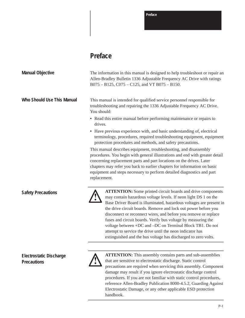
Manual Objective The information in this manual is designed to help troubleshoot or repair anAllen-Bradley Bulletin 1336 Adjustable Frequency AC Drive with ratingsB075 – B125, C075 – C125, and VT B075 – B150.
Who Should Use This Manual This manual is intended for qualified service personnel responsible fortroubleshooting and repairing the 1336 Adjustable Frequency AC Drive.You should:
• Read this entire manual before performing maintenance or repairs todrives.
• Have previous experience with, and basic understanding of, electricalterminology, procedures, required troubleshooting equipment, equipmentprotection procedures and methods, and safety precautions.
This manual describes equipment, troubleshooting, and disassemblyprocedures. You begin with general illustrations and end with greater detailconcerning replacement parts and part locations on the drives. Laterchapters may refer you back to earlier chapters for information on basicequipment and steps necessary to perform detailed diagnostics and partreplacement.
ATTENTION: Some printed circuit boards and drive componentsmay contain hazardous voltage levels. If neon light DS 1 on theBase Driver Board is illuminated, hazardous voltages are present inthe drive circuit boards. Remove and lock out power before youdisconnect or reconnect wires, and before you remove or replacefuses and circuit boards. Verify bus voltage by measuring thevoltage between +DC and –DC on Terminal Block TB1. Do notattempt to service the drive until the neon indicator hasextinguished and the bus voltage has discharged to zero volts.
Safety Precautions
ATTENTION: This assembly contains parts and sub-assembliesthat are sensitive to electrostatic discharge. Static controlprecautions are required when servicing this assembly. Componentdamage may result if you ignore electrostatic discharge controlprocedures. If you are not familiar with static control procedures,reference Allen-Bradley Publication 8000-4.5.2, Guarding AgainstElectrostatic Damage, or any other applicable ESD protectionhandbook.
Electrostatic DischargePrecautions
Preface
P-2
Electrostatic discharge generated by static electricity can damage thecomplimentary metallic oxide semiconductor devices on various driveboards. It is recommended that you perform these procedures to guardagainst this type of damage when circuit boards are removed or installed:
• Wear a wrist type grounding strap that is grounded to the drive chassis.
• Attach the wrist strap before removing the new circuit board from theconductive packet.
• Remove boards from the drive and immediately insert them into theirconductive packets.
1336 Product Identification
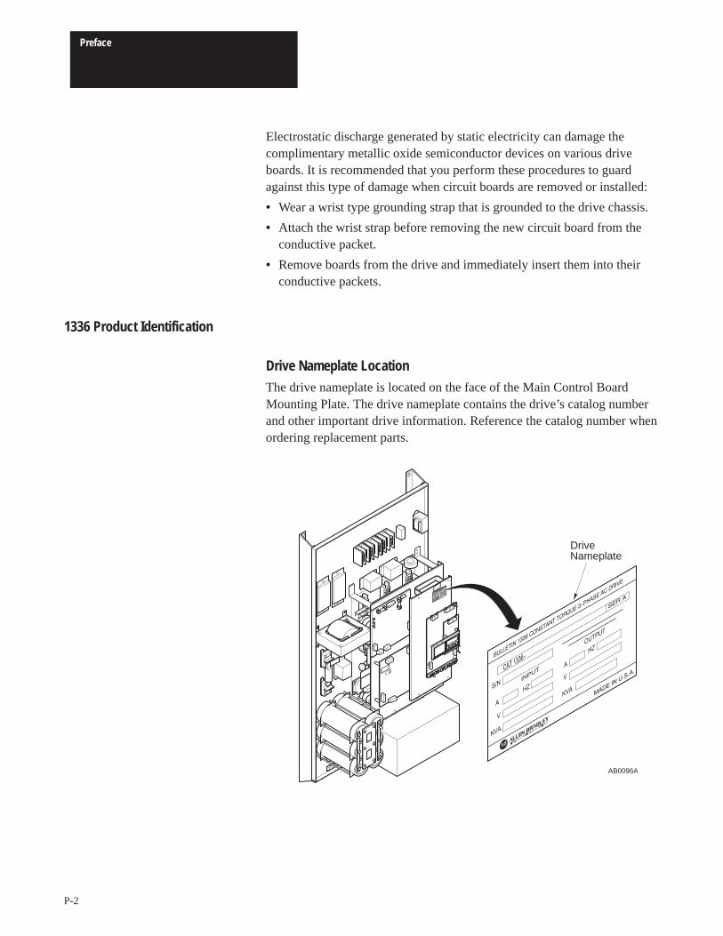
Drive Nameplate LocationThe drive nameplate is located on the face of the Main Control BoardMounting Plate. The drive nameplate contains the drive’s catalog numberand other important drive information. Reference the catalog number whenordering replacement parts.
DriveNameplate
AB0096A
Preface
P-3
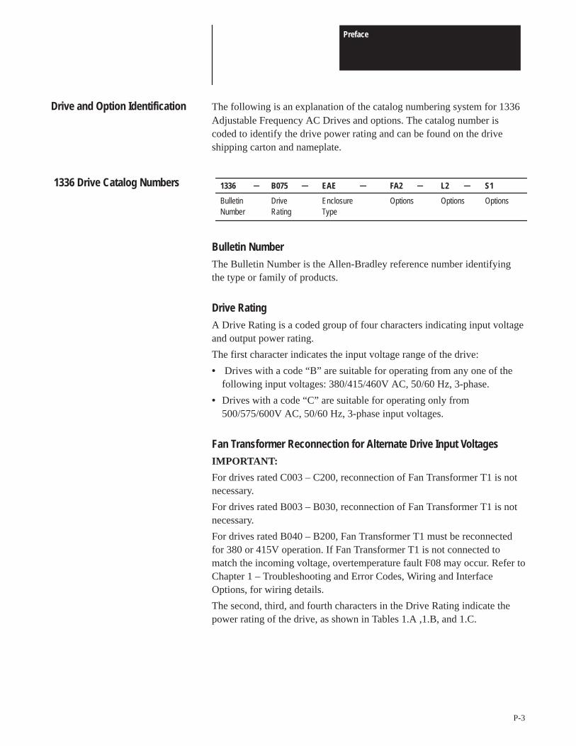
Drive and Option Identification The following is an explanation of the catalog numbering system for 1336Adjustable Frequency AC Drives and options. The catalog number iscoded to identify the drive power rating and can be found on the driveshipping carton and nameplate.
1336 B075 EAE FA2 L2 S1
Bulletin Drive Enclosure Options Options OptionsNumber Rating Type
1336 Drive Catalog Numbers
Bulletin NumberThe Bulletin Number is the Allen-Bradley reference number identifyingthe type or family of products.
Drive RatingA Drive Rating is a coded group of four characters indicating input voltageand output power rating.
The first character indicates the input voltage range of the drive:
• Drives with a code “B” are suitable for operating from any one of thefollowing input voltages: 380/415/460V AC, 50/60 Hz, 3-phase.
• Drives with a code “C” are suitable for operating only from500/575/600V AC, 50/60 Hz, 3-phase input voltages.
Fan Transformer Reconnection for Alternate Drive Input VoltagesIMPORTANT:
For drives rated C003 – C200, reconnection of Fan Transformer T1 is notnecessary.
For drives rated B003 – B030, reconnection of Fan Transformer T1 is notnecessary.
For drives rated B040 – B200, Fan Transformer T1 must be reconnectedfor 380 or 415V operation. If Fan Transformer T1 is not connected tomatch the incoming voltage, overtemperature fault F08 may occur. Refer toChapter 1 – Troubleshooting and Error Codes, Wiring and InterfaceOptions, for wiring details.
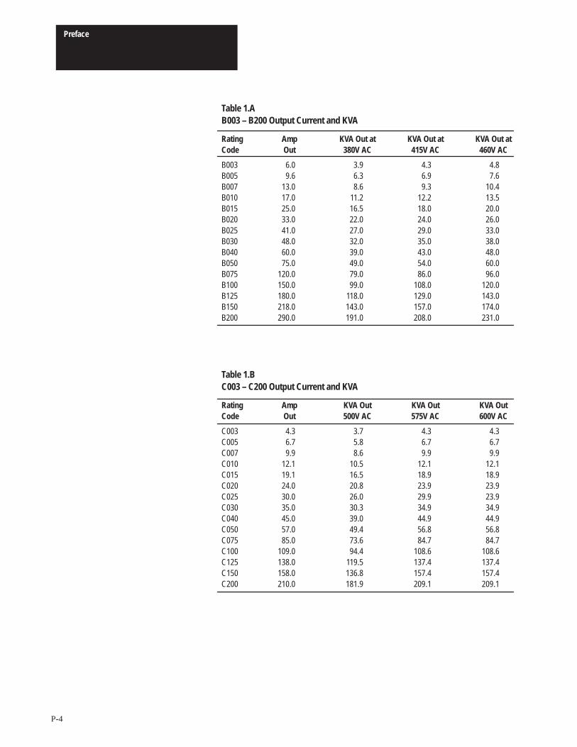
The second, third, and fourth characters in the Drive Rating indicate thepower rating of the drive, as shown in Tables 1.A ,1.B, and 1.C.
Preface
P-4
Table 1.AB003 – B200 Output Current and KVA
Rating Amp KVA Out at KVA Out at KVA Out atCode Out 380V AC 415V AC 460V AC
B003 6.0 3.9 4.3 4.8B005 9.6 6.3 6.9 7.6B007 13.0 8.6 9.3 10.4B010 17.0 11.2 12.2 13.5B015 25.0 16.5 18.0 20.0B020 33.0 22.0 24.0 26.0B025 41.0 27.0 29.0 33.0B030 48.0 32.0 35.0 38.0B040 60.0 39.0 43.0 48.0B050 75.0 49.0 54.0 60.0B075 120.0 79.0 86.0 96.0B100 150.0 99.0 108.0 120.0B125 180.0 118.0 129.0 143.0B150 218.0 143.0 157.0 174.0B200 290.0 191.0 208.0 231.0
Table 1.BC003 – C200 Output Current and KVA
Rating Amp KVA Out KVA Out KVA OutCode Out 500V AC 575V AC 600V AC
C003 4.3 3.7 4.3 4.3C005 6.7 5.8 6.7 6.7C007 9.9 8.6 9.9 9.9C010 12.1 10.5 12.1 12.1C015 19.1 16.5 18.9 18.9C020 24.0 20.8 23.9 23.9C025 30.0 26.0 29.9 23.9C030 35.0 30.3 34.9 34.9C040 45.0 39.0 44.9 44.9C050 57.0 49.4 56.8 56.8C075 85.0 73.6 84.7 84.7C100 109.0 94.4 108.6 108.6C125 138.0 119.5 137.4 137.4C150 158.0 136.8 157.4 157.4C200 210.0 181.9 209.1 209.1
Preface
P-5
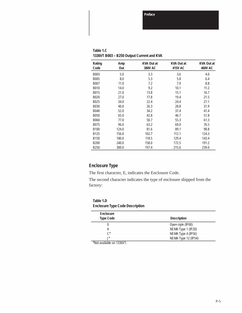
Table 1.C1336VT B003 – B250 Output Current and KVA
Rating Amp KVA Out at KVA Out at KVA Out atCode Out 380V AC 415V AC 460V AC
B003 5.0 3.3 3.6 4.0B005 8.0 5.3 5.8 6.4B007 11.0 7.2 7.9 8.8B010 14.0 9.2 10.1 11.2B015 21.0 13.8 15.1 16.7B020 27.0 17.8 19.4 21.5B025 34.0 22.4 24.4 27.1B030 40.0 26.3 28.8 31.9B040 52.0 34.2 37.4 41.4B050 65.0 42.8 46.7 51.8B060 77.0 50.7 55.3 61.3B075 96.0 63.2 69.0 76.5B100 124.0 81.6 89.1 98.8B125 156.0 102.7 112.1 124.3B150 180.0 118.5 129.4 143.4B200 240.0 158.0 172.5 191.2B250 300.0 197.4 215.6 239.0
Enclosure TypeThe first character, E, indicates the Enclosure Code.
The second character indicates the type of enclosure shipped from thefactory:
Table 1.DEnclosure Type Code Description
EnclosureType Code Description
0 Open style (IP00)A NEMA Type 1 (IP20)C* NEMA Type 4 (IP56)J* NEMA Type 12 (IP54)
*Not available on 1336VT.
Preface
P-6
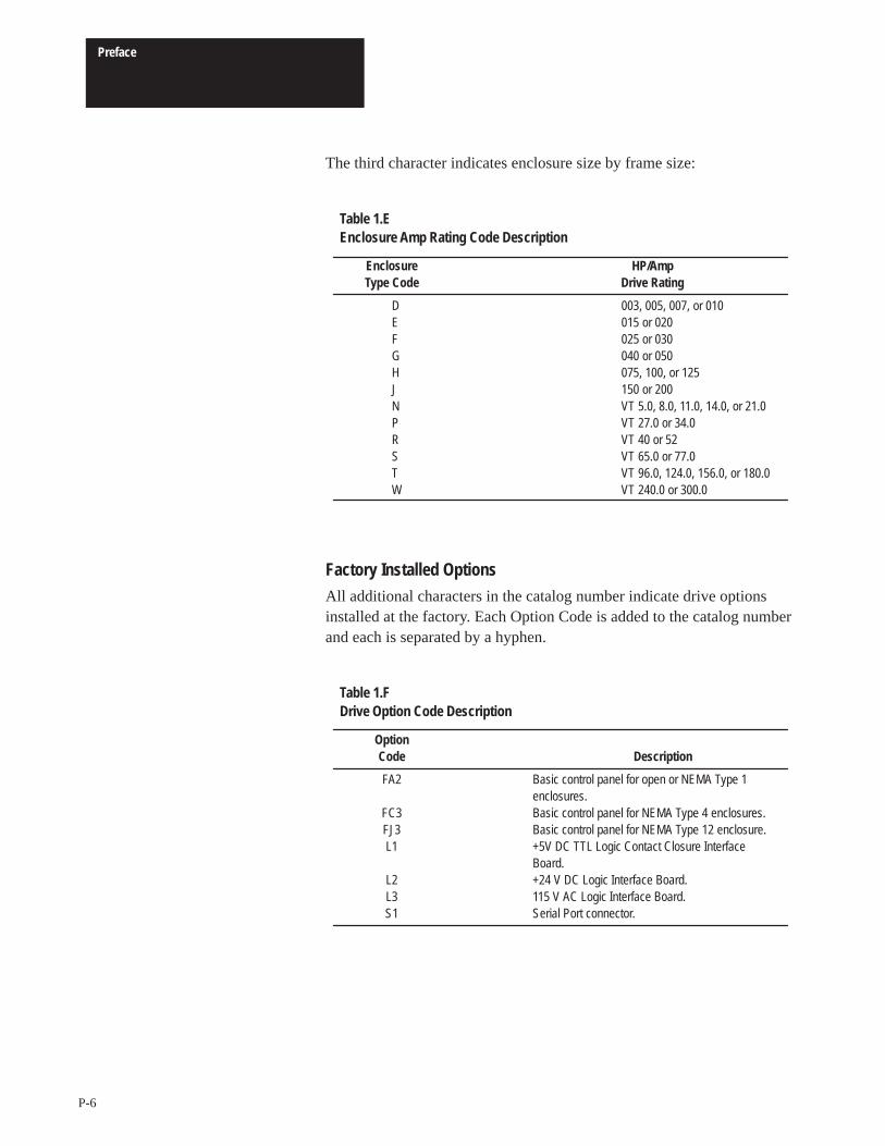
The third character indicates enclosure size by frame size:
Table 1.EEnclosure Amp Rating Code Description
Enclosure HP/AmpType Code Drive Rating
D 003, 005, 007, or 010E 015 or 020F 025 or 030G 040 or 050H 075, 100, or 125J 150 or 200N VT 5.0, 8.0, 11.0, 14.0, or 21.0P VT 27.0 or 34.0R VT 40 or 52S VT 65.0 or 77.0T VT 96.0, 124.0, 156.0, or 180.0W VT 240.0 or 300.0
Factory Installed OptionsAll additional characters in the catalog number indicate drive optionsinstalled at the factory. Each Option Code is added to the catalog numberand each is separated by a hyphen.
Table 1.FDrive Option Code Description
OptionCode Description
FA2 Basic control panel for open or NEMA Type 1 enclosures.
FC3 Basic control panel for NEMA Type 4 enclosures.FJ3 Basic control panel for NEMA Type 12 enclosure.L1 +5V DC TTL Logic Contact Closure Interface
Board.L2 +24 V DC Logic Interface Board.L3 115 V AC Logic Interface Board.S1 Serial Port connector.
Preface
P-7
Conventions The following is a list of conventions used throughout this manual, anddefinitions of the conventions. For a list of terminology and definitions,refer to the Glossary in the back of this manual.
AUX InputThe AUX (Auxiliary Interlock) Input is a terminal connection on the LogicInterface Board. This connection provides a mandatory input for startcommands. The drive will not recognize a Start command unless the AUXInput is logically true.
Auxiliary InterlockThe Auxiliary Interlock is a user supplied circuit such as reset, overload, orsome logical true-state connection associated with the drive AUX input.
BitA bit is a single character or status point used in programmable logic. Eightbits form a BYTE, 16 bits form a word. Drive parameters are actually eightbits or 16 bit words.
CheckTo check means to examine either the physical condition of something orthe setting of some control, such as a Parameter. Checking a drive board orcomponent may also require measurements and tests.
ConnectorA connector connects one drive board to another. Connectors come in twodesigns, male and female. Male connectors are stationary and contain pins,which are sometimes joined by jumpers. Female connectors are mobile andplug into male connectors.
DefaultWhen a drive function defaults, it automatically changes to apre-programmed setting.
Enable InputThe Enable Input is a terminal connection on the Logic Interface Board.This connection provides similar functions as the AUX Input. It must alsobe true to permit the drive to operate.

Preface
P-8
FalseFalse refers to a logical false state. For instance, the Logic Interface signalson TB3, Terminal 22, are false when MOD-L1 contact is open or theappropriate voltage is not applied to the L2 or L3.
Hand-Held TerminalA hand-held terminal is a 1336-MOD-E1 programming terminal that plugsinto the Serial Interface Port. This terminal allows you to adjust Parameterswhile the drive is operating.
JumperA jumper completes a circuit between two pins within a male connector ona drive board. In the absence of certain optional equipment using femaleconnectors, jumpers are applied to certain pins within a male connector tocomplete specific and necessary circuits.
Logic Interface BoardA Logic Interface Board connects to junctions J8 and J9, located on thelower portion of the Main Control Board. This board is identified asMOD-L1, -L2, or -L3 and provides optional control wiring configurationsfor a drive.
ParameterParameters are programmable drive functions that define various operatingmodes of a drive. Refer to Bulletin 1336 Adjustable Frequency AC DriveProgramming Manual for Parameter details.
PressPress a button on the drive’s Programming and Display Board to changeParameter settings and drive functions, or to program the drive.
SetIn this manual, set refers to entering information into the drive by changingParameter values or by changing a setting on a selector switch.
TrueTrue refers to a logical true state. For instance, the Logic Interface signalson TB3, Terminal 22, are true when: MOD-L1 is controlled by a contactclosure only and no voltage is present; MOD-L2 registers 24V DC;MOD-L3 registers 115V AC.

Preface
P-9
Related Publications The following lists other Allen-Bradley publications that apply to the 1336Adjustable Frequency AC Drives with ratings B075 – B125, C075 – C125,and VT B075 – B150:
• Hardware Manual
• Programming Manual
• Renewal Parts List

Preface
P-10
This Page Intentionally Left Blank
Chapter
1-1
Troubleshooting and Error Codes
Chapter Objectives This chapter helps you trace faults to field-replaceable components.
Troubleshooting Overview To troubleshoot a 1336 Adjustable Frequency AC Drive, you need thefollowing:
• A Range DVM, DMM, or VOM with a range capacity of at least 1000 V.
• An oscilloscope with a frequency-response range of at least 1 MHz.
• A1336-MOD-E1.
IMPORTANT: All printed circuit boards, except the Main Control Boardassembly, are referenced to negative ground (-bus).
ATTENTION: Some printed circuit boards and drive componentsmay contain hazardous voltage levels. If neon light DS1 on theBase Driver Board is illuminated, hazardous voltages are present inthe drive circuit boards. Remove power before you disconnect orreconnect wires, and before you remove or replace fuses and circuitboards. Verify bus voltage by measuring the voltage between +DCand –DC on Terminal Block TB1. Do not attempt to service thedrive until the neon indicator has extinguished and the bus voltagehas discharged to zero volts.
ATTENTION: To guard against equipment damage whentroubleshooting the drive, always check the following beforeissuing a Start command:
• Set the Speed Reference to minimum.• Select the proper motor-rotation direction.• Disconnect the motor from its mechanical load.
ATTENTION: This assembly contains parts and sub-assembliesthat are sensitive to electrostatic discharge. Static controlprecautions are required when servicing this assembly. Componentdamage may result if you ignore electrostatic discharge controlprocedures. If you are not familiar with static control procedures,reference Allen-Bradley Publication 8000 – 4.5.2, GuardingAgainst Electrostatic Discharge, or any other applicable ESDprotection handbook.
Chapter 1Troubleshooting and Error Codes
1-2
Electrostatic Discharge Precautions Electrostatic Discharge generated by static electricity can damage the
complimentary metallic oxide semiconductor devices on various driveboards. It is recommended that you perform these procedures to guardagainst this type of damage when circuit boards are removed or installed:
• Wear a wrist type grounding strap that is grounded to the chassis.
• Attach the wrist strap before removing the new circuit board from theconductive packet.
• Remove boards from the drive and immediately insert them into theirconductive packets.
IMPORTANT: Before clearing a fault, refer to the Fault Code Descriptiontable and Diagnostic Procedures by Symptom flowchart in this chapter toisolate and correct faults.
Detailed Product Identification Allen-Bradley Adjustable Frequency AC Drives are modular by design toenhance troubleshooting and spare parts replacement, thereby reduceproduction down-time.
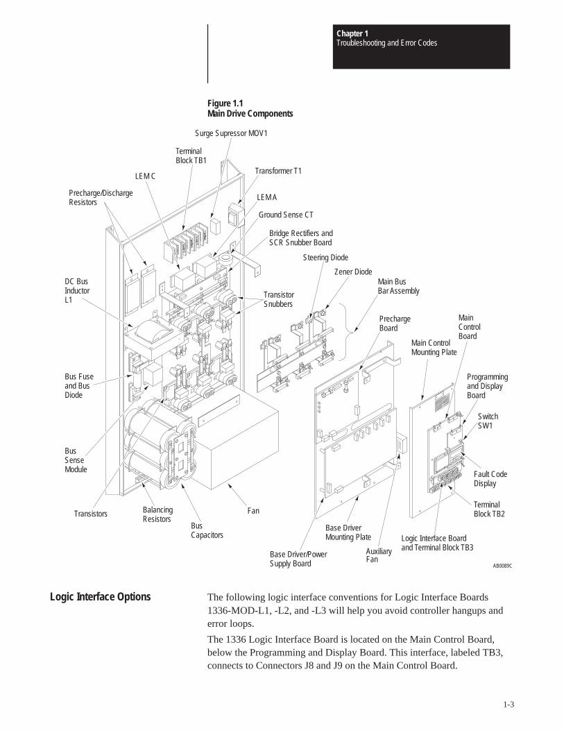
The following illustration calls out the main components of a B075, C075,or 1336VT B075 drive, as discussed in this chapter. Component designsvary slightly among the different drive ratings, but component locations areidentical.
Chapter 1Troubleshooting and Error Codes
1-3
Figure 1.1Main Drive Components
AB0089C
Base Driver/PowerSupply Board
Base DriverMounting Plate
Main BusBar Assembly
Zener Diode
Steering Diode
Surge Supressor MOV1
Main ControlMounting Plate
MainControlBoard
Programmingand DisplayBoard
Switch SW1
Fault CodeDisplay
TerminalBlock TB2
Logic Interface Boardand Terminal Block TB3
PrechargeBoard
TransistorSnubbers
Bridge Rectifiers andSCR Snubber Board
Ground Sense CT
LEM A
Transformer T1
FanBalancingResistors
BusSenseModule
Transistors
Bus Fuseand BusDiode
DC BusInductorL1
Precharge/DischargeResistors
LEM C
TerminalBlock TB1
BusCapacitors
AuxiliaryFan
Logic Interface Options The following logic interface conventions for Logic Interface Boards1336-MOD-L1, -L2, and -L3 will help you avoid controller hangups anderror loops.
The 1336 Logic Interface Board is located on the Main Control Board,below the Programming and Display Board. This interface, labeled TB3,connects to Connectors J8 and J9 on the Main Control Board.
Chapter 1Troubleshooting and Error Codes
1-4
1336-MOD-L1 Logic Interface Options
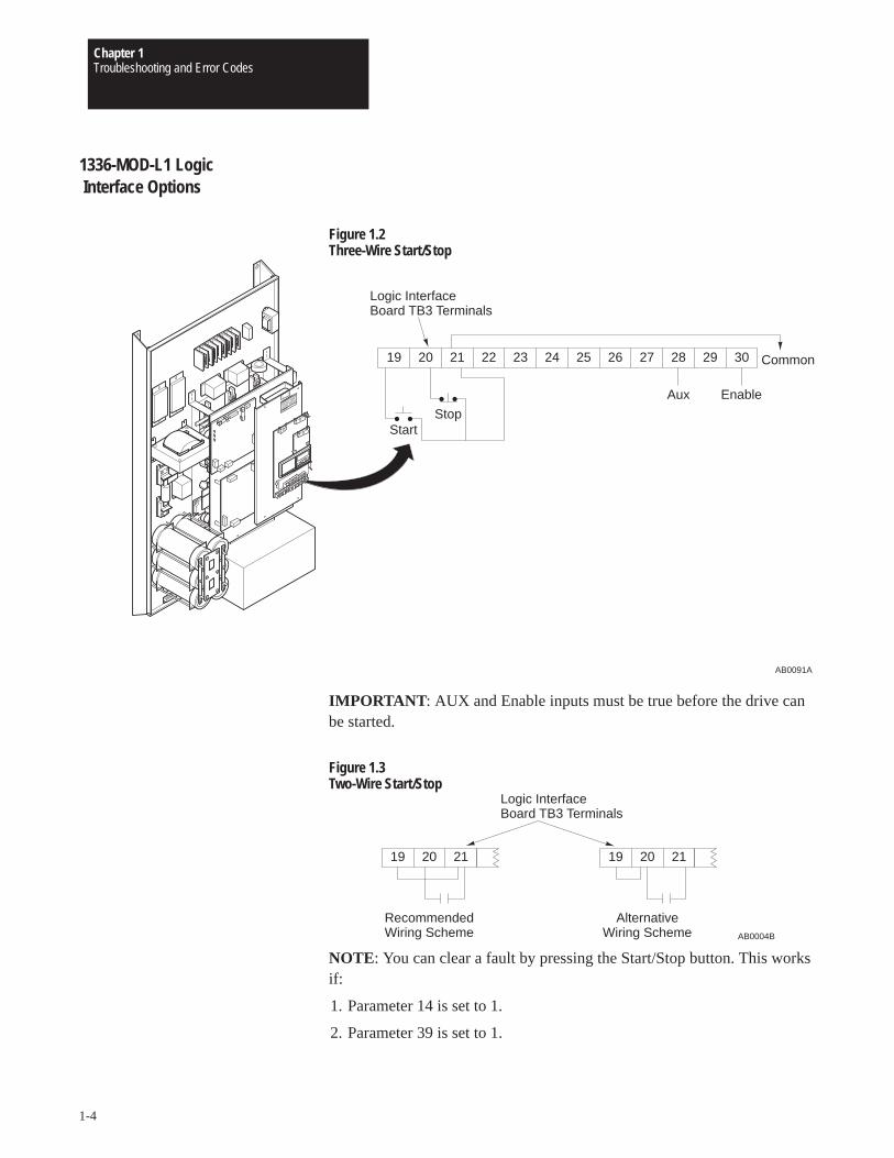
Figure 1.2Three-Wire Start/Stop
AB0091A
Logic InterfaceBoard TB3 Terminals
19 20 21 22 23 24 25 26 27 28 29 30
Aux Enable
StartStop
Common
IMPORTANT : AUX and Enable inputs must be true before the drive canbe started.
Figure 1.3Two-Wire Start/Stop
19 20 21 19 20 21
Logic InterfaceBoard TB3 Terminals
RecommendedWiring Scheme
AlternativeWiring Scheme AB0004B
NOTE: You can clear a fault by pressing the Start/Stop button. This worksif:
1. Parameter 14 is set to 1.
2. Parameter 39 is set to 1.
Chapter 1Troubleshooting and Error Codes
1-5
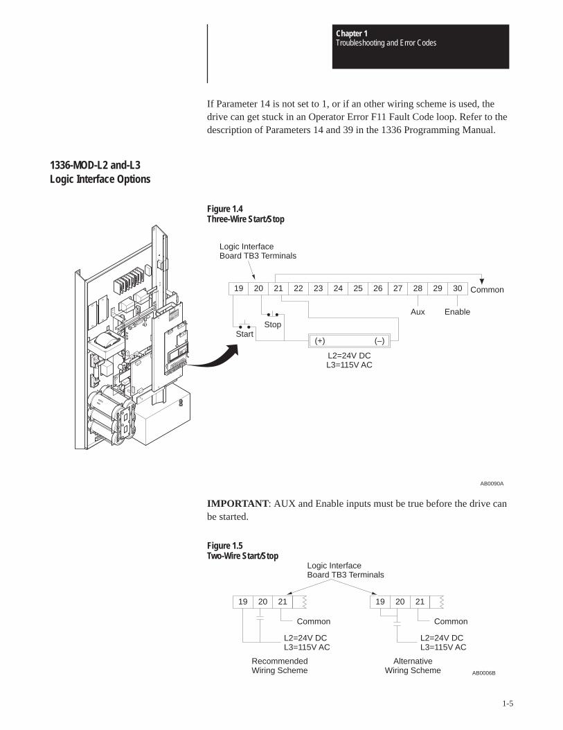
If Parameter 14 is not set to 1, or if an other wiring scheme is used, thedrive can get stuck in an Operator Error F11 Fault Code loop. Refer to thedescription of Parameters 14 and 39 in the 1336 Programming Manual.
1336-MOD-L2 and-L3 Logic Interface Options
Figure 1.4Three-Wire Start/Stop
AB0090A
27 28 29 30
Aux Enable
Common19 20 21 22 23 24 25 26
StartStop
(+) (–)
L2=24V DCL3=115V AC
Logic InterfaceBoard TB3 Terminals
IMPORTANT : AUX and Enable inputs must be true before the drive canbe started.
Figure 1.5Two-Wire Start/Stop
19 20 21 19 20 21
Logic InterfaceBoard TB3 Terminals
RecommendedWiring Scheme
AlternativeWiring Scheme AB0006B
L2=24V DCL3=115V AC
Common
L2=24V DCL3=115V AC
Common
Chapter 1Troubleshooting and Error Codes
1-6
NOTE: You can clear a fault by pressing the Start/Stop button. This worksif:
1. Parameter 14 is set to 1.
2. Parameter 39 is set to 1.
If Parameter 14 is not set to 1, or if an other wiring scheme is used, thedrive can get stuck in an Operator Error F11 Fault Code loop. Refer to thedescription of Parameters 14 and 39 in the 1336 Programming Manual.
Basic Drive Control and Diagnostic procedures refer to both program panel and optional localFault Display control panel. The following information on operation is also located in the
Hardware Manual and Programming Manual. It is provided here for yourconvenience during troubleshooting.
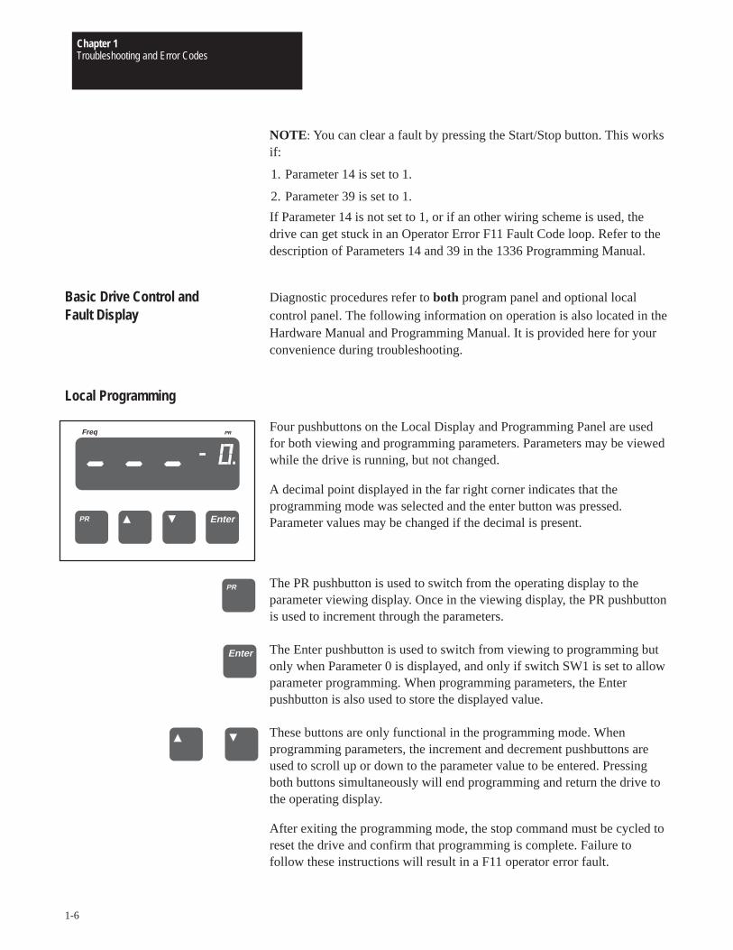
Local Programming
Four pushbuttons on the Local Display and Programming Panel are usedfor both viewing and programming parameters. Parameters may be viewedwhile the drive is running, but not changed.
A decimal point displayed in the far right corner indicates that theprogramming mode was selected and the enter button was pressed.Parameter values may be changed if the decimal is present.
The PR pushbutton is used to switch from the operating display to theparameter viewing display. Once in the viewing display, the PR pushbuttonis used to increment through the parameters.
The Enter pushbutton is used to switch from viewing to programming butonly when Parameter 0 is displayed, and only if switch SW1 is set to allowparameter programming. When programming parameters, the Enterpushbutton is also used to store the displayed value.
These buttons are only functional in the programming mode. Whenprogramming parameters, the increment and decrement pushbuttons areused to scroll up or down to the parameter value to be entered. Pressingboth buttons simultaneously will end programming and return the drive tothe operating display.
After exiting the programming mode, the stop command must be cycled toreset the drive and confirm that programming is complete. Failure tofollow these instructions will result in a F11 operator error fault.
EnterPR
ÎÎÎÎ
ÎÎÎÎÎÎÎÎÎÎÎÎ
Freq PR
ÎÎÎÎ
PR
Enter
Chapter 1Troubleshooting and Error Codes
1-7
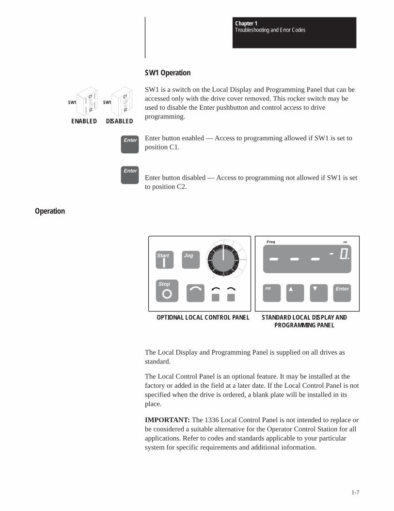
SW1 Operation
SW1 is a switch on the Local Display and Programming Panel that can beaccessed only with the drive cover removed. This rocker switch may beused to disable the Enter pushbutton and control access to driveprogramming.
Enter button enabled — Access to programming allowed if SW1 is set toposition C1.
Enter button disabled — Access to programming not allowed if SW1 is setto position C2.
Operation
Jog
Stop
Start
OPTIONAL LOCAL CONTROL PANEL STANDARD LOCAL DISPLAY ANDPROGRAMMING PANEL
Freq PR
EnterPR
ÎÎÎ
ÎÎÎÎÎÎÎÎÎÎÎÎÎÎÎË
The Local Display and Programming Panel is supplied on all drives asstandard.
The Local Control Panel is an optional feature. It may be installed at thefactory or added in the field at a later date. If the Local Control Panel is notspecified when the drive is ordered, a blank plate will be installed in itsplace.
IMPORTANT: The 1336 Local Control Panel is not intended to replace orbe considered a suitable alternative for the Operator Control Station for allapplications. Refer to codes and standards applicable to your particularsystem for specific requirements and additional information.
SW1 SW1
ENABLED DISABLED
Enter
Enter
Chapter 1Troubleshooting and Error Codes
1-8
Drive Restart
IMPORTANT: The 1336 drive is programmed to avoid responding tounintentional start commands. The stop input to the drive must first befalse, then returned to true to restart the drive:
• When exiting programming at the Local Programming and DisplayPanel.
• After a power-on reset fault has occurred, if Parameter 14 is set to 0.
– F01 power-on reset is displayed when power is first applied to thedrive and when a fault is cleared.
– If Parameter 14 is set to 1, cycling a stop input is not required afterreapplying power or clearing a fault.
If this sequence is not followed, the drive will fault and display F11.
When Parameter 14 is set to 0, the stop command must be repeated twice,once to clear the fault, then again to reset drive logic once the fault hasbeen cleared.
A stop input is any valid stop signal that the drive receives. Valid stopinputs are:
• The Stop pushbutton on the Local Control Panel — As shown on thefollowing page.
• The stop input wired to TB3 at Terminal 20 — As explained inAppendix A, Logic Interface Options.
• When serial communications is used, writing to Parameter 51 to clearthe fault, then setting the stop bit of the serial input control word inParameter 57 — As explained in the 1336 Programming Manual.
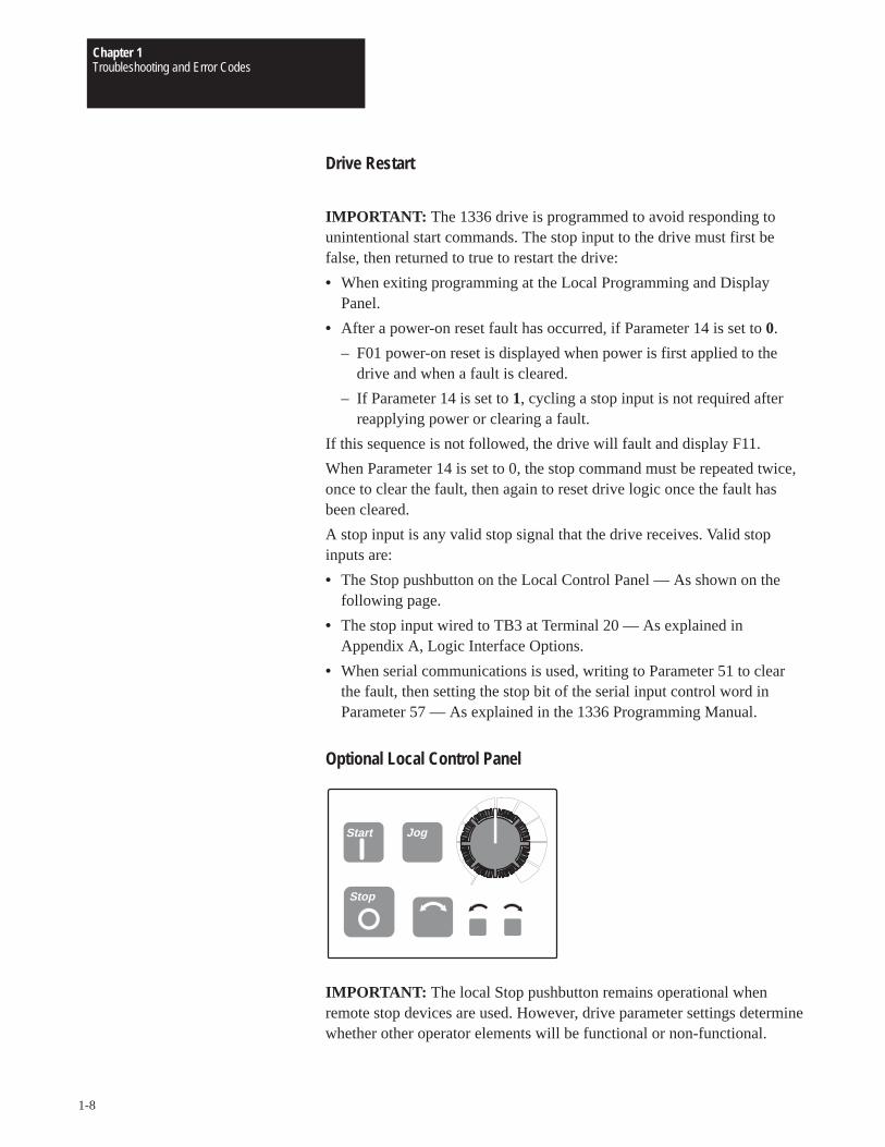
Optional Local Control Panel
Jog
Stop
Start
IMPORTANT: The local Stop pushbutton remains operational whenremote stop devices are used. However, drive parameter settings determinewhether other operator elements will be functional or non-functional.
Chapter 1Troubleshooting and Error Codes
1-9
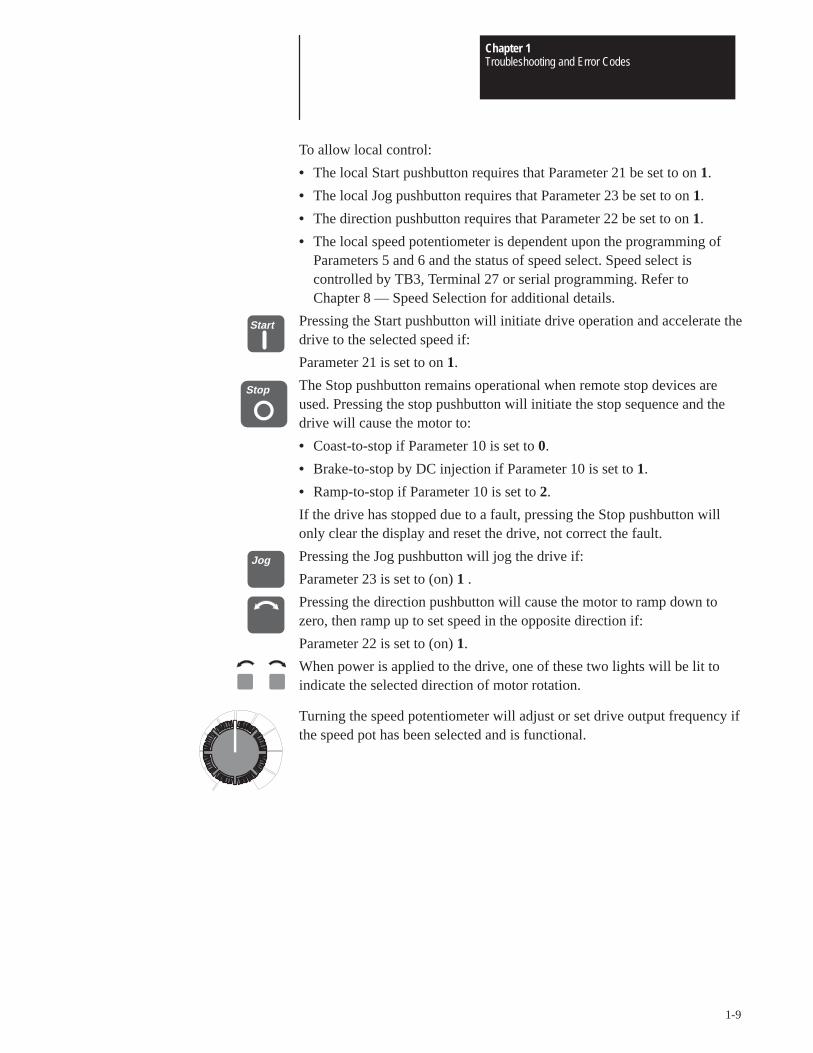
To allow local control:
• The local Start pushbutton requires that Parameter 21 be set to on 1.
• The local Jog pushbutton requires that Parameter 23 be set to on 1.
• The direction pushbutton requires that Parameter 22 be set to on 1.
• The local speed potentiometer is dependent upon the programming ofParameters 5 and 6 and the status of speed select. Speed select iscontrolled by TB3, Terminal 27 or serial programming. Refer to Chapter 8 — Speed Selection for additional details.
Pressing the Start pushbutton will initiate drive operation and accelerate thedrive to the selected speed if:
Parameter 21 is set to on 1.
The Stop pushbutton remains operational when remote stop devices areused. Pressing the stop pushbutton will initiate the stop sequence and thedrive will cause the motor to:
• Coast-to-stop if Parameter 10 is set to 0.
• Brake-to-stop by DC injection if Parameter 10 is set to 1.
• Ramp-to-stop if Parameter 10 is set to 2.
If the drive has stopped due to a fault, pressing the Stop pushbutton willonly clear the display and reset the drive, not correct the fault.
Pressing the Jog pushbutton will jog the drive if:
Parameter 23 is set to (on) 1 .
Pressing the direction pushbutton will cause the motor to ramp down tozero, then ramp up to set speed in the opposite direction if:
Parameter 22 is set to (on) 1.
When power is applied to the drive, one of these two lights will be lit toindicate the selected direction of motor rotation.
Turning the speed potentiometer will adjust or set drive output frequency ifthe speed pot has been selected and is functional.
Start
Stop
Jog
Chapter 1Troubleshooting and Error Codes
1-10
Standard Local Display and Programming Panel
EnterPR
ÎÎÎÎÎ
ÎÎÎÎ
ÎÎÎÎÎÎÎÎÎÎÎÎ
Freq PR
ÎÎÎÎÎÎ
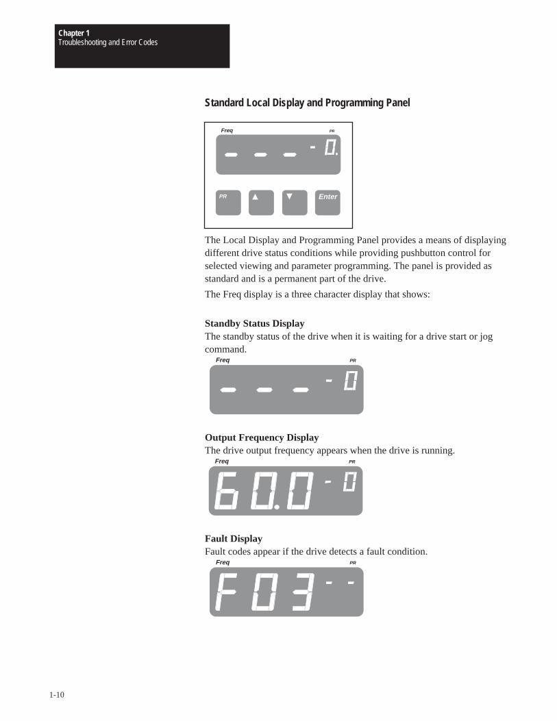
The Local Display and Programming Panel provides a means of displayingdifferent drive status conditions while providing pushbutton control forselected viewing and parameter programming. The panel is provided asstandard and is a permanent part of the drive.
The Freq display is a three character display that shows:
Standby Status DisplayThe standby status of the drive when it is waiting for a drive start or jogcommand.
Freq PR
Output Frequency DisplayThe drive output frequency appears when the drive is running.
Freq PR
Fault DisplayFault codes appear if the drive detects a fault condition.
Freq PR
Chapter 1Troubleshooting and Error Codes
1-11
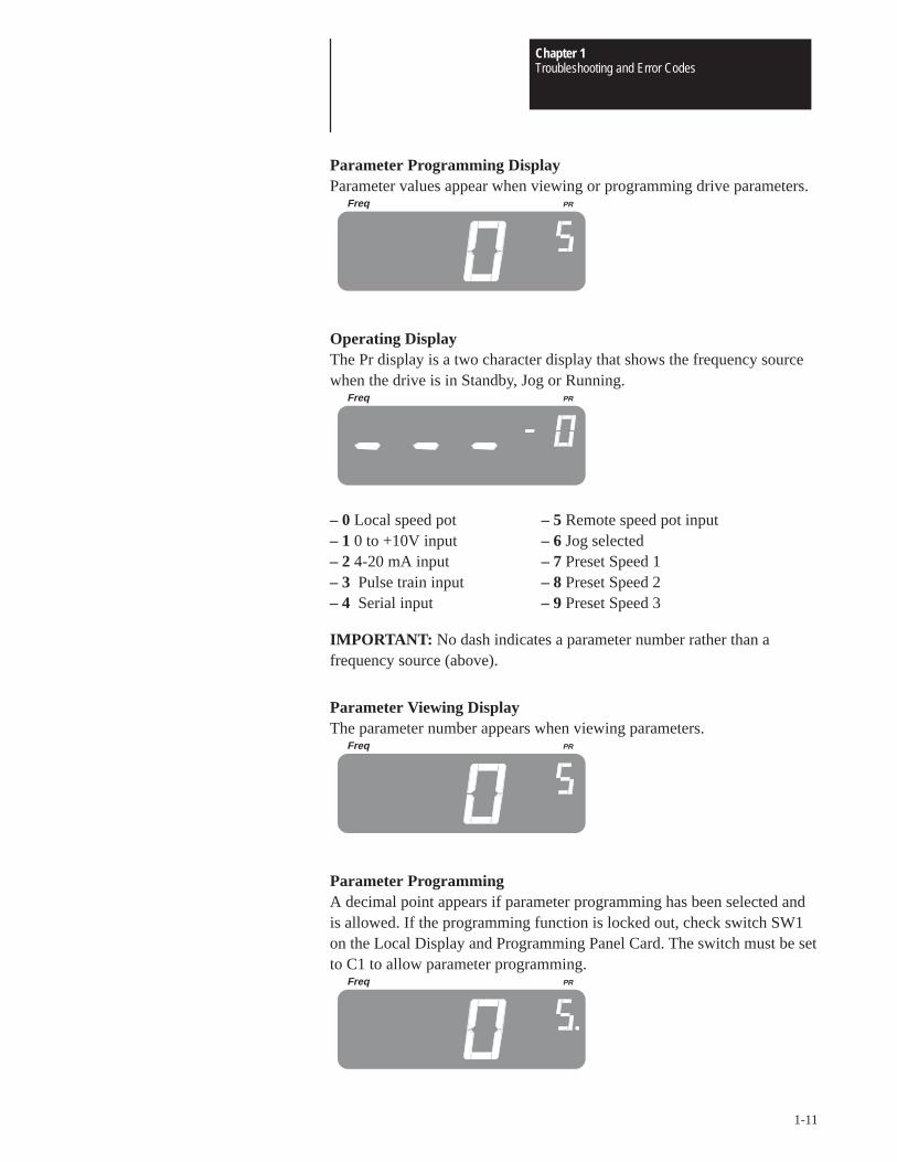
Parameter Programming DisplayParameter values appear when viewing or programming drive parameters.
Freq PR
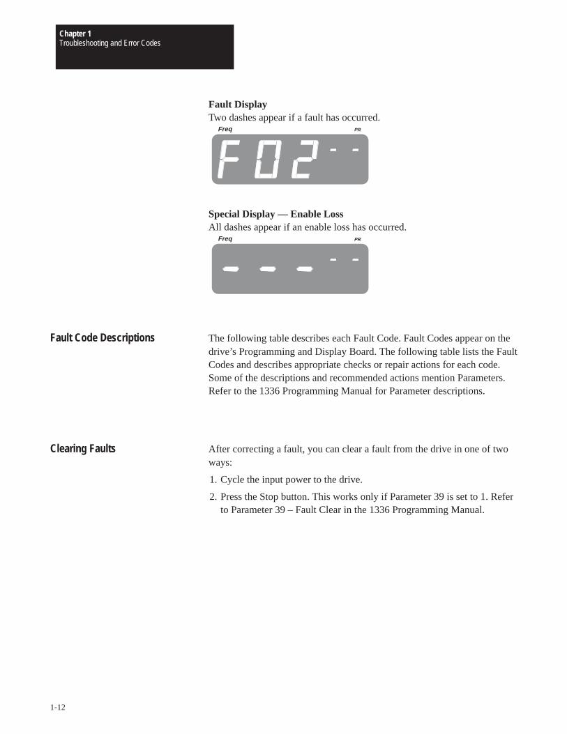
Operating DisplayThe Pr display is a two character display that shows the frequency sourcewhen the drive is in Standby, Jog or Running.
Freq PR
– 0 Local speed pot – 5 Remote speed pot input– 1 0 to +10V input – 6 Jog selected– 2 4-20 mA input – 7 Preset Speed 1– 3 Pulse train input – 8 Preset Speed 2– 4 Serial input – 9 Preset Speed 3
IMPORTANT: No dash indicates a parameter number rather than afrequency source (above).
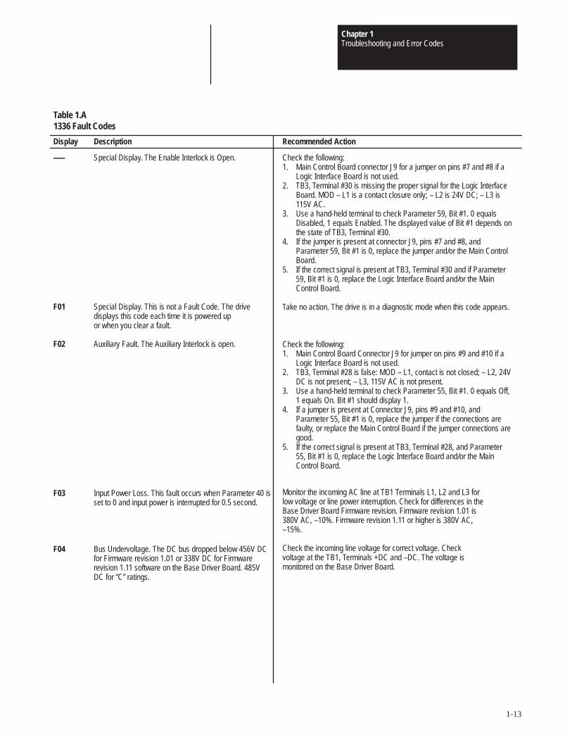
Parameter Viewing DisplayThe parameter number appears when viewing parameters.
Freq PR
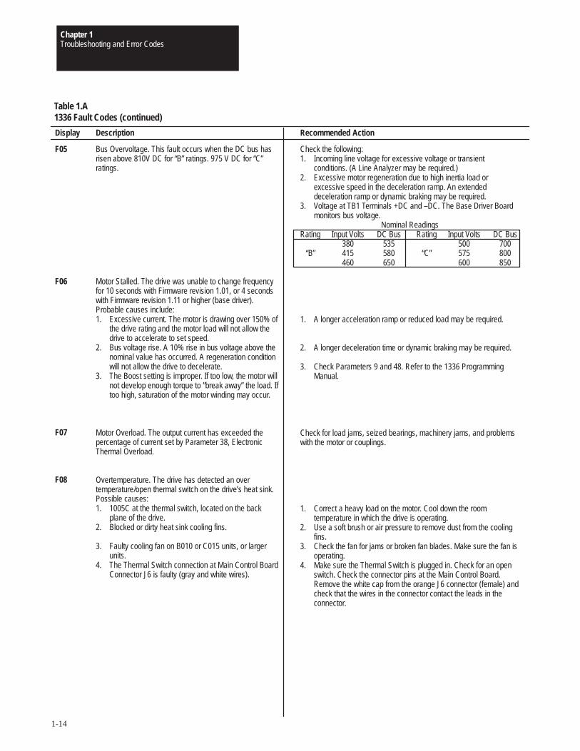
Parameter ProgrammingA decimal point appears if parameter programming has been selected andis allowed. If the programming function is locked out, check switch SW1on the Local Display and Programming Panel Card. The switch must be setto C1 to allow parameter programming.
Freq PR
Chapter 1Troubleshooting and Error Codes
1-12
Fault DisplayTwo dashes appear if a fault has occurred.
Freq PR
Special Display — Enable LossAll dashes appear if an enable loss has occurred.
Freq PR
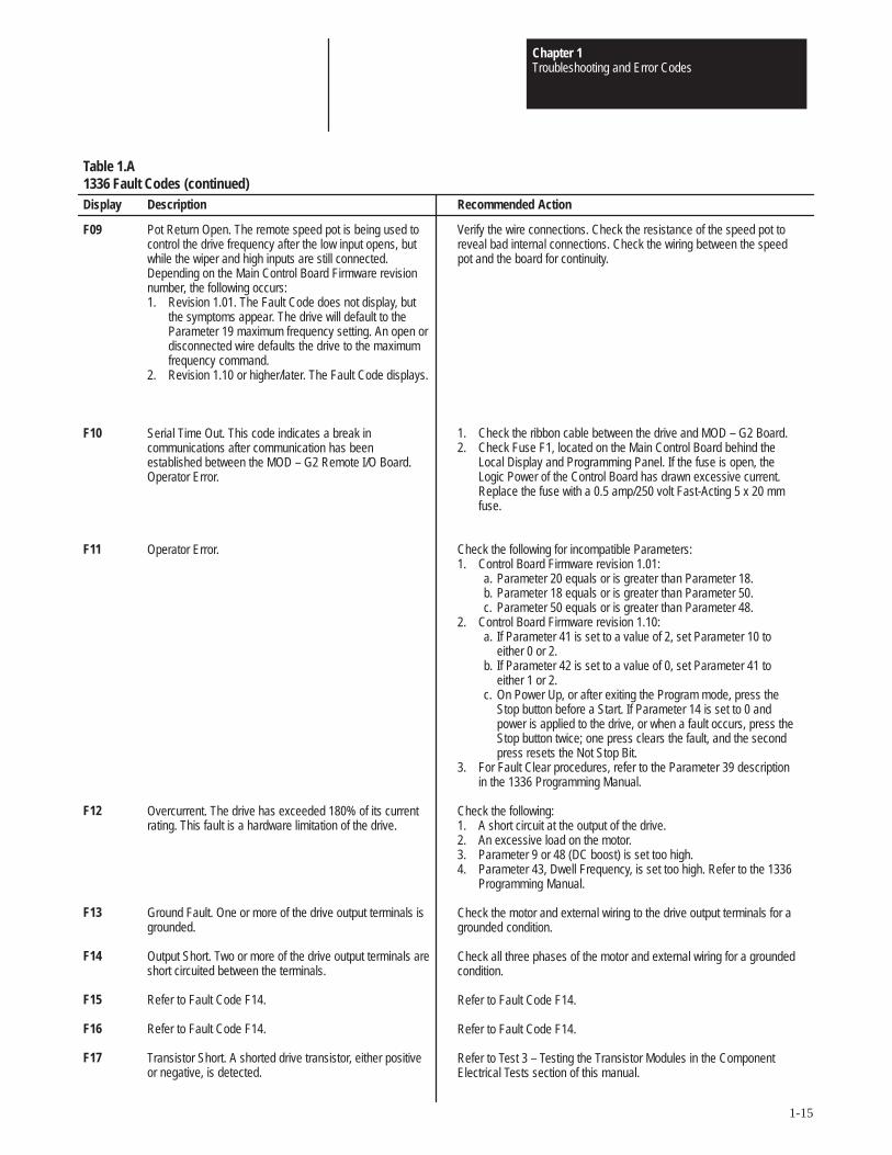
Fault Code Descriptions The following table describes each Fault Code. Fault Codes appear on thedrive’s Programming and Display Board. The following table lists the FaultCodes and describes appropriate checks or repair actions for each code.Some of the descriptions and recommended actions mention Parameters.Refer to the 1336 Programming Manual for Parameter descriptions.
Clearing Faults After correcting a fault, you can clear a fault from the drive in one of twoways:
1. Cycle the input power to the drive.
2. Press the Stop button. This works only if Parameter 39 is set to 1. Referto Parameter 39 – Fault Clear in the 1336 Programming Manual.
Chapter 1Troubleshooting and Error Codes
1-13
Display
-----
F01
F02
F03
F04
Table 1.A1336 Fault Codes
Description
Special Display. The Enable Interlock is Open.
Special Display. This is not a Fault Code. The drivedisplays this code each time it is powered up or when you clear a fault.
Auxiliary Fault. The Auxiliary Interlock is open.
Input Power Loss. This fault occurs when Parameter 40 isset to 0 and input power is interrupted for 0.5 second.
Bus Undervoltage. The DC bus dropped below 456V DCfor Firmware revision 1.01 or 338V DC for Firmwarerevision 1.11 software on the Base Driver Board. 485VDC for “C” ratings.
Recommended Action
Check the following:1. Main Control Board connector J9 for a jumper on pins #7 and #8 if a
Logic Interface Board is not used.2. TB3, Terminal #30 is missing the proper signal for the Logic Interface
Board. MOD – L1 is a contact closure only; – L2 is 24V DC; – L3 is115V AC.
3. Use a hand-held terminal to check Parameter 59, Bit #1. 0 equalsDisabled, 1 equals Enabled. The displayed value of Bit #1 depends onthe state of TB3, Terminal #30.
4. If the jumper is present at connector J9, pins #7 and #8, andParameter 59, Bit #1 is 0, replace the jumper and/or the Main ControlBoard.
5. If the correct signal is present at TB3, Terminal #30 and if Parameter59, Bit #1 is 0, replace the Logic Interface Board and/or the MainControl Board.
Take no action. The drive is in a diagnostic mode when this code appears.
Check the following:1. Main Control Board Connector J9 for jumper on pins #9 and #10 if a
Logic Interface Board is not used.2. TB3, Terminal #28 is false: MOD – L1, contact is not closed; – L2, 24V
DC is not present; – L3, 115V AC is not present.3. Use a hand-held terminal to check Parameter 55, Bit #1. 0 equals Off,
1 equals On. Bit #1 should display 1.4. If a jumper is present at Connector J9, pins #9 and #10, and
Parameter 55, Bit #1 is 0, replace the jumper if the connections arefaulty, or replace the Main Control Board if the jumper connections aregood.
5. If the correct signal is present at TB3, Terminal #28, and Parameter55, Bit #1 is 0, replace the Logic Interface Board and/or the MainControl Board.
Monitor the incoming AC line at TB1 Terminals L1, L2 and L3 forlow voltage or line power interruption. Check for differences in theBase Driver Board Firmware revision. Firmware revision 1.01 is380V AC, –10%. Firmware revision 1.11 or higher is 380V AC,–15%.
Check the incoming line voltage for correct voltage. Checkvoltage at the TB1, Terminals +DC and –DC. The voltage ismonitored on the Base Driver Board.
Chapter 1Troubleshooting and Error Codes
1-14
Display
F05
F06
F07
F08
Table 1.A1336 Fault Codes (continued)
Description
Bus Overvoltage. This fault occurs when the DC bus hasrisen above 810V DC for “B” ratings. 975 V DC for “C”ratings.
Motor Stalled. The drive was unable to change frequencyfor 10 seconds with Firmware revision 1.01, or 4 secondswith Firmware revision 1.11 or higher (base driver).Probable causes include:1. Excessive current. The motor is drawing over 150% of
the drive rating and the motor load will not allow thedrive to accelerate to set speed.
2. Bus voltage rise. A 10% rise in bus voltage above thenominal value has occurred. A regeneration conditionwill not allow the drive to decelerate.
3. The Boost setting is improper. If too low, the motor willnot develop enough torque to ”break away” the load. Iftoo high, saturation of the motor winding may occur.
Motor Overload. The output current has exceeded thepercentage of current set by Parameter 38, ElectronicThermal Overload.
Overtemperature. The drive has detected an overtemperature/open thermal switch on the drive’s heat sink.Possible causes:1. 1005C at the thermal switch, located on the back
plane of the drive.2. Blocked or dirty heat sink cooling fins.
3. Faulty cooling fan on B010 or C015 units, or largerunits.
4. The Thermal Switch connection at Main Control BoardConnector J6 is faulty (gray and white wires).
Recommended Action
Check the following:1. Incoming line voltage for excessive voltage or transient
conditions. (A Line Analyzer may be required.)2. Excessive motor regeneration due to high inertia load or
excessive speed in the deceleration ramp. An extendeddeceleration ramp or dynamic braking may be required.
3. Voltage at TB1 Terminals +DC and –DC. The Base Driver Boardmonitors bus voltage.
Nominal ReadingsRating Input Volts DC Bus Rating Input Volts DC Bus
380 535 500 700“B” 415 580 “C” 575 800
460 650 600 850
1. A longer acceleration ramp or reduced load may be required.
2. A longer deceleration time or dynamic braking may be required.
3. Check Parameters 9 and 48. Refer to the 1336 ProgrammingManual.
Check for load jams, seized bearings, machinery jams, and problemswith the motor or couplings.
1. Correct a heavy load on the motor. Cool down the roomtemperature in which the drive is operating.
2. Use a soft brush or air pressure to remove dust from the coolingfins.
3. Check the fan for jams or broken fan blades. Make sure the fan isoperating.
4. Make sure the Thermal Switch is plugged in. Check for an openswitch. Check the connector pins at the Main Control Board.Remove the white cap from the orange J6 connector (female) andcheck that the wires in the connector contact the leads in theconnector.
Chapter 1Troubleshooting and Error Codes
1-15
Recommended Action
Verify the wire connections. Check the resistance of the speed pot toreveal bad internal connections. Check the wiring between the speedpot and the board for continuity.
1. Check the ribbon cable between the drive and MOD – G2 Board.2. Check Fuse F1, located on the Main Control Board behind the
Local Display and Programming Panel. If the fuse is open, theLogic Power of the Control Board has drawn excessive current.Replace the fuse with a 0.5 amp/250 volt Fast-Acting 5 x 20 mmfuse.
Check the following for incompatible Parameters:1. Control Board Firmware revision 1.01:
a. Parameter 20 equals or is greater than Parameter 18.b. Parameter 18 equals or is greater than Parameter 50.c. Parameter 50 equals or is greater than Parameter 48.
2. Control Board Firmware revision 1.10:a. If Parameter 41 is set to a value of 2, set Parameter 10 to
either 0 or 2.b. If Parameter 42 is set to a value of 0, set Parameter 41 to
either 1 or 2.c. On Power Up, or after exiting the Program mode, press the
Stop button before a Start. If Parameter 14 is set to 0 andpower is applied to the drive, or when a fault occurs, press theStop button twice; one press clears the fault, and the secondpress resets the Not Stop Bit.
3. For Fault Clear procedures, refer to the Parameter 39 descriptionin the 1336 Programming Manual.
Check the following:1. A short circuit at the output of the drive.2. An excessive load on the motor.3. Parameter 9 or 48 (DC boost) is set too high.4. Parameter 43, Dwell Frequency, is set too high. Refer to the 1336
Programming Manual.
Check the motor and external wiring to the drive output terminals for agrounded condition.
Check all three phases of the motor and external wiring for a groundedcondition.
Refer to Fault Code F14.
Refer to Fault Code F14.
Refer to Test 3 – Testing the Transistor Modules in the ComponentElectrical Tests section of this manual.
Table 1.A1336 Fault Codes (continued)
Description
Pot Return Open. The remote speed pot is being used tocontrol the drive frequency after the low input opens, butwhile the wiper and high inputs are still connected.Depending on the Main Control Board Firmware revisionnumber, the following occurs:1. Revision 1.01. The Fault Code does not display, but
the symptoms appear. The drive will default to theParameter 19 maximum frequency setting. An open ordisconnected wire defaults the drive to the maximumfrequency command.
2. Revision 1.10 or higher/later. The Fault Code displays.
Serial Time Out. This code indicates a break incommunications after communication has beenestablished between the MOD – G2 Remote I/O Board.Operator Error.
Operator Error.
Overcurrent. The drive has exceeded 180% of its currentrating. This fault is a hardware limitation of the drive.
Ground Fault. One or more of the drive output terminals isgrounded.
Output Short. Two or more of the drive output terminals areshort circuited between the terminals.
Refer to Fault Code F14.
Refer to Fault Code F14.
Transistor Short. A shorted drive transistor, either positiveor negative, is detected.
Display
F09
F10
F11
F12
F13
F14
F15
F16
F17
Chapter 1Troubleshooting and Error Codes
1-16
Recommended Action
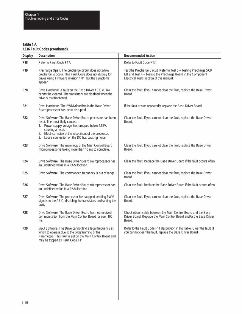
Refer to Fault Code F17.
Test the Precharge Circuit. Refer to Test 5 – Testing Precharge SCRM1 and Test 4 – Testing the Precharge Board in the ComponentElectrical Tests section of this manual.
Clear the fault. If you cannot clear the fault, replace the Base DriverBoard.
If the fault occurs repeatedly, replace the Base Driver Board.
Clear the fault. If you cannot clear the fault, replace the Base DriverBoard.
Clear the fault. If you cannot clear the fault, replace the Base DriverBoard.
Clear the fault. Replace the Base Driver Board if the fault occurs often.
Clear the fault. If you cannot clear the fault, replace the Base DriverBoard.
Clear the fault. Replace the Base Driver Board if the fault occurs often.
Clear the fault. If you cannot clear the fault, replace the Base DriverBoard.
Check ribbon cable between the Main Control Board and the BaseDriver Board. Replace the Main Control Board and/or the Base DriverBoard.
Refer to the Fault Code F11 description in this table. Clear the fault. Ifyou cannot clear the fault, replace the Base Driver Board.
Table 1.A1336 Fault Codes (continued)
Description
Refer to Fault Code F17.
Precharge Open. The precharge circuit does not allowprecharge to occur. This Fault Code does not display fordrives using Firmware revision 1.01, but the symptomsappear.
Drive Hardware. A fault on the Base Driver ASIC (U14)cannot be cleared. The transistors are disabled when thedrive is malfunctioned.
Drive Hardware. The PWM algorithm in the Base DriverBoard processor has been disrupted.
Drive Software. The Base Driver Board processor has beenreset. The most likely causes:1. Power supply voltage has dropped below 4.55V,
causing a reset.2. Electrical noise at the reset input of the processor.3. Loose connection on the DC bus causing noise.
Drive Software. The main loop of the Main Control Boardmicroprocessor is taking more than 10 ms to complete.
Drive Software. The Base Driver Board microprocessor hasan undefined value in a RAM location.
Drive Software. The commanded frequency is out of range.
Drive Software. The Base Driver Board microprocessor hasan undefined value in a RAM location.
Drive Software. The processor has stopped sending PWMsignals to the ASIC, disabling the transistors and setting thefault.
Drive Software. The Base Driver Board has not receivedcommunication from the Main Control Board for over 100ms.
Input Software. The Drive cannot find a legal frequency atwhich to operate due to the programming of theParameters. This fault is set on the Main Control Board andmay be tripped as Fault Code F11.
Display
F18
F19
F20
F21
F22
F23
F24
F25
F26
F27
F28
F29
Chapter 1Troubleshooting and Error Codes
1-17
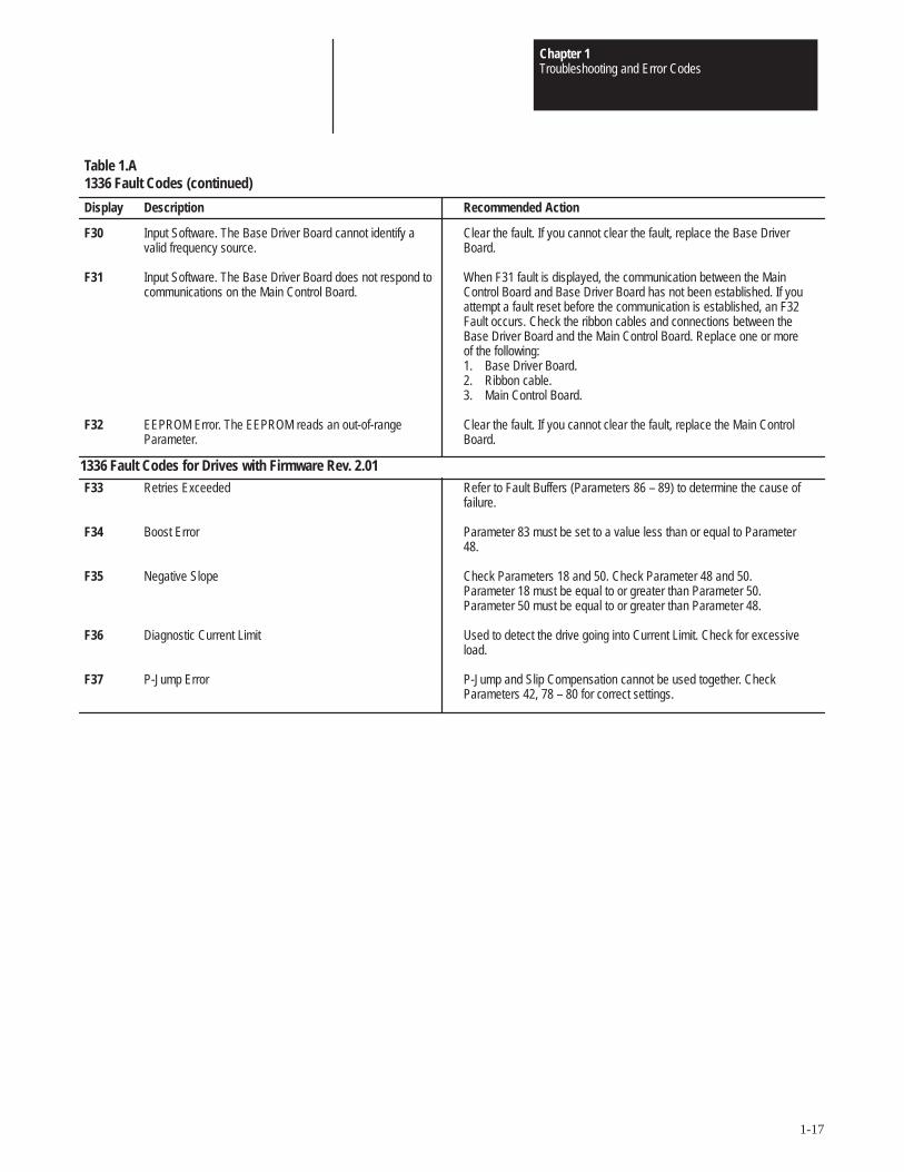
Recommended Action
Clear the fault. If you cannot clear the fault, replace the Base DriverBoard.
When F31 fault is displayed, the communication between the MainControl Board and Base Driver Board has not been established. If youattempt a fault reset before the communication is established, an F32Fault occurs. Check the ribbon cables and connections between theBase Driver Board and the Main Control Board. Replace one or moreof the following:1. Base Driver Board.2. Ribbon cable.3. Main Control Board.
Clear the fault. If you cannot clear the fault, replace the Main ControlBoard.
Table 1.A1336 Fault Codes (continued)
Description
Input Software. The Base Driver Board cannot identify avalid frequency source.
Input Software. The Base Driver Board does not respond tocommunications on the Main Control Board.
EEPROM Error. The EEPROM reads an out-of-rangeParameter.
Display
F30
F31
F32
1336 Fault Codes for Drives with Firmware Rev. 2.01Retries Exceeded
Boost Error
Negative Slope
Diagnostic Current Limit
P-Jump Error
Refer to Fault Buffers (Parameters 86 – 89) to determine the cause offailure.
Parameter 83 must be set to a value less than or equal to Parameter48.
Check Parameters 18 and 50. Check Parameter 48 and 50.Parameter 18 must be equal to or greater than Parameter 50.Parameter 50 must be equal to or greater than Parameter 48.
Used to detect the drive going into Current Limit. Check for excessiveload.
P-Jump and Slip Compensation cannot be used together. CheckParameters 42, 78 – 80 for correct settings.
F33
F34
F35
F36
F37
Chapter 1Troubleshooting and Error Codes
1-18
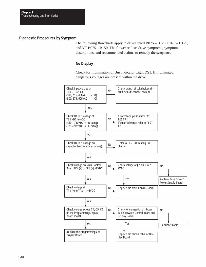
Diagnostic Procedures by SymptomThe following flowcharts apply to drives rated B075 – B125, C075 – C125,and VT B075 – B150. The flowchart lists drive symptoms, symptomdescriptions, and recommended actions to remedy the symptoms.
No Display
Check for illumination of Bus Indicator Light DS1. If illuminated,dangerous voltages are present within the drive.
Replace Base Driver/Power Supply Board
Check for connection of ribboncable between Control Board andDisplay Board
Check input voltage at TB1 L1, L2, L3(380, 415, 460VAC = B)(500, 575, 600VAC = C)
Check branch circuit devices (in-put fuses, disconnect switch)
Yes
Check DC bus voltage at TB1 +DC to –DC(460 – 710VDC = B rating)(725 – 925VDC = C rating)
If no voltage present refer toTEST #1.If out of tolerance refer to TEST#2.
Check DC bus voltage on capacitor bank (same as above)
Refer to TEST #4 Testing Pre-charge
Yes
Yes
Check voltage on Main ControlBoard TP2 (+) to TP3 (–) +9VDC
Check voltage at J7 pin 1 to 29VAC
No
No
No
NoNo
Yes
Check voltage at TP1 (+) to TP3 (–) +5VDC
No Replace the Main Control Board
Yes
Check voltage across C4, C5, C6on the Programming/DisplayBoard +5VDC
No
Yes
Replace the Programming andDisplay Board
Connect cable
Replace the ribbon cable or Dis-play Board
Yes
No
Yes
Chapter 1Troubleshooting and Error Codes
1-19
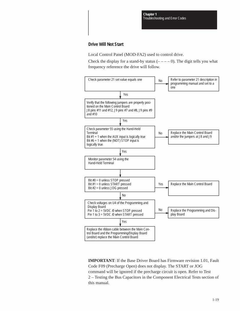
Drive Will Not Start
Local Control Panel (MOD-FA2) used to control drive.
Check the display for a stand-by status (– – – – 0). The digit tells you whatfrequency reference the drive will follow.
Check parameter 21 set value equals one Refer to parameter 21 description inprogramming manual and set to aone
Yes
Verify that the following jumpers are properly posi-tioned on the Main Control BoardJ8 pins #11 and #12, J9 pins #7 and #8, J9 pins #9and #10
Check parameter 55 using the Hand-Held TerminalBit #1 = 1 when the AUX input is logically trueBit #6 = 1 when the (NOT) STOP input is logically true
Yes
Yes
Monitor parameter 54 using the Hand-Held Terminal
Replace the Main Control Boardand/or the jumpers at J8 and J9
No
No
Bit #0 = 0 unless STOP pressedBit #1 = 0 unless START pressedBit #2 = 0 unless JOG pressed
Yes Replace the Main Control Board
No
Check voltages on U4 of the Programming andDisplay Board Pin 1 to 2 = 5VDC /0 when STOP pressedPin 1 to 3 = 5VDC /0 when START pressed
Yes
Replace the ribbon cable between the Main Con-trol Board and the Programming/Display Board(and/or) replace the Main Control Board
Replace the Programming and Dis-play Board
No
IMPORTANT : If the Base Driver Board has Firmware revision 1.01, FaultCode F09 (Precharge Open) does not display. The START or JOGcommand will be ignored if the precharge circuit is open. Refer to Test2 – Testing the Bus Capacitors in the Component Electrical Tests section ofthis manual.
Chapter 1Troubleshooting and Error Codes
1-20
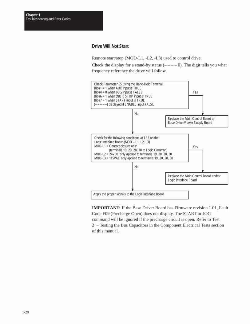
Drive Will Not Start
Remote start/stop (MOD-L1, -L2, -L3) used to control drive.
Check the display for a stand-by status (– – – – 0). The digit tells you whatfrequency reference the drive will follow.
Check Parameter 55 using the Hand-Held Terminal.Bit #1 = 1 when AUX input is TRUEBit #4 = 0 when JOG input is FALSEBit #6 = 1 when (NOT) STOP input is TRUEBit #7 = 1 when START input is TRUE(– – – – –) displayed if ENABLE input FALSE
Replace the Main Control Board or Base Driver/Power Supply Board
Check for the following conditions at TB3 on the Logic Interface Board (MOD – L1, L2, L3)MOD-L1 = Contact closure only
(terminals 19, 20, 28, 30 to Logic Common)MOD-L2 = 24VDC only applied to terminals 19, 20, 28, 30MOD-L3 = 115VAC only applied to terminals 19, 20, 28, 30
No
Yes
Apply the proper signals to the Logic Interface Board
No
Replace the Main Control Board and/or Logic Interface Board
Yes
IMPORTANT: If the Base Driver Board has Firmware revision 1.01, FaultCode F09 (Precharge Open) does not display. The START or JOGcommand will be ignored if the precharge circuit is open. Refer to Test2 – Testing the Bus Capacitors in the Component Electrical Tests sectionof this manual.
Chapter 1Troubleshooting and Error Codes
1-21
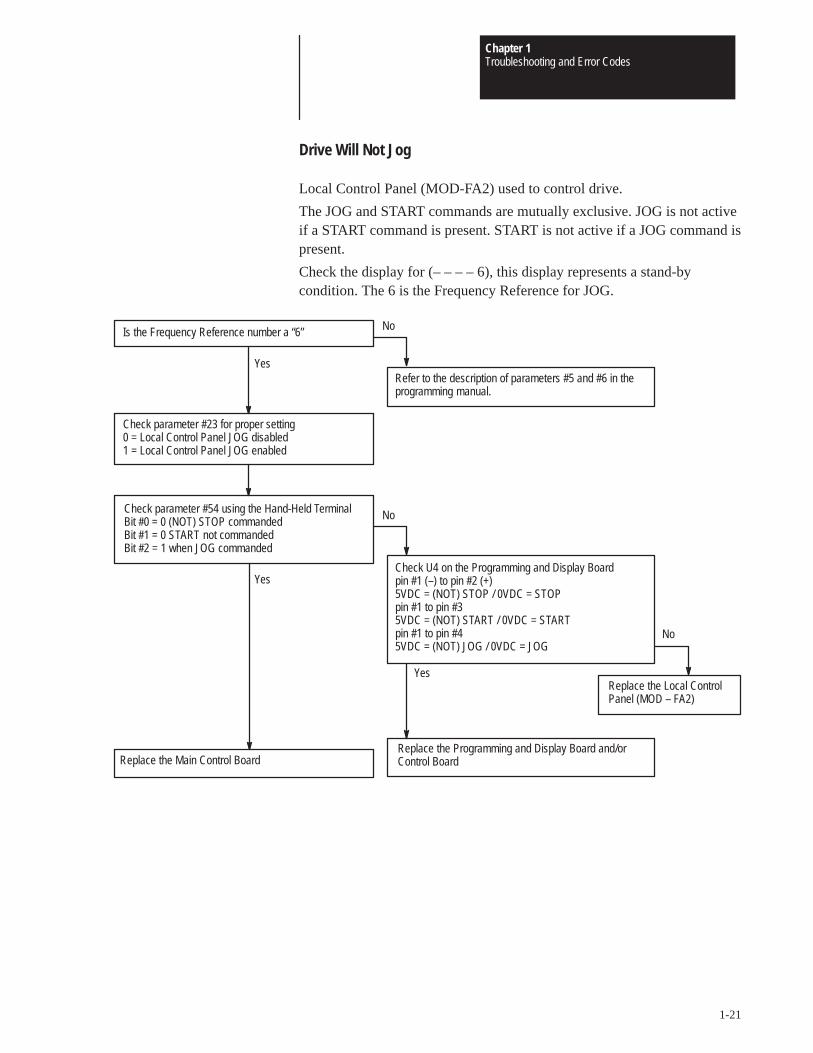
Drive Will Not Jog
Local Control Panel (MOD-FA2) used to control drive.
The JOG and START commands are mutually exclusive. JOG is not activeif a START command is present. START is not active if a JOG command ispresent.
Check the display for (– – – – 6), this display represents a stand-bycondition. The 6 is the Frequency Reference for JOG.
Check U4 on the Programming and Display Boardpin #1 (–) to pin #2 (+)5VDC = (NOT) STOP / 0VDC = STOPpin #1 to pin #35VDC = (NOT) START / 0VDC = STARTpin #1 to pin #45VDC = (NOT) JOG / 0VDC = JOG
Refer to the description of parameters #5 and #6 in theprogramming manual.
Check parameter #54 using the Hand-Held TerminalBit #0 = 0 (NOT) STOP commandedBit #1 = 0 START not commandedBit #2 = 1 when JOG commanded
Yes
No
Replace the Main Control Board
Yes
Check parameter #23 for proper setting0 = Local Control Panel JOG disabled1 = Local Control Panel JOG enabled
No
Replace the Local ControlPanel (MOD – FA2)
Yes
Replace the Programming and Display Board and/orControl Board
Is the Frequency Reference number a “6”
No
Chapter 1Troubleshooting and Error Codes
1-22
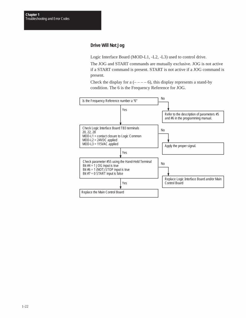
Drive Will Not Jog
Logic Interface Board (MOD-L1, -L2, -L3) used to control drive.
The JOG and START commands are mutually exclusive. JOG is not activeif a START command is present. START is not active if a JOG command ispresent.
Check the display for a (– – – – 6), this display represents a stand-bycondition. The 6 is the Frequency Reference for JOG.
Is the Frequency Reference number a “6”
Refer to the description of parameters #5and #6 in the programming manual.
Check parameter #55 using the Hand-Held TerminalBit #4 = 1 JOG input is trueBit #6 = 1 (NOT) STOP input is trueBit #7 = 0 START input is false
Yes
No
Replace the Main Control Board
Yes
Check Logic Interface Board TB3 terminals 20, 22, 28MOD-L1 = contact closure to Logic CommonMOD-L2 = 24VDC appliedMOD-L3 = 115VAC applied
No
No
Apply the proper signal.
Replace Logic Interface Board and/or MainControl Board
Yes
Chapter 1Troubleshooting and Error Codes
1-23
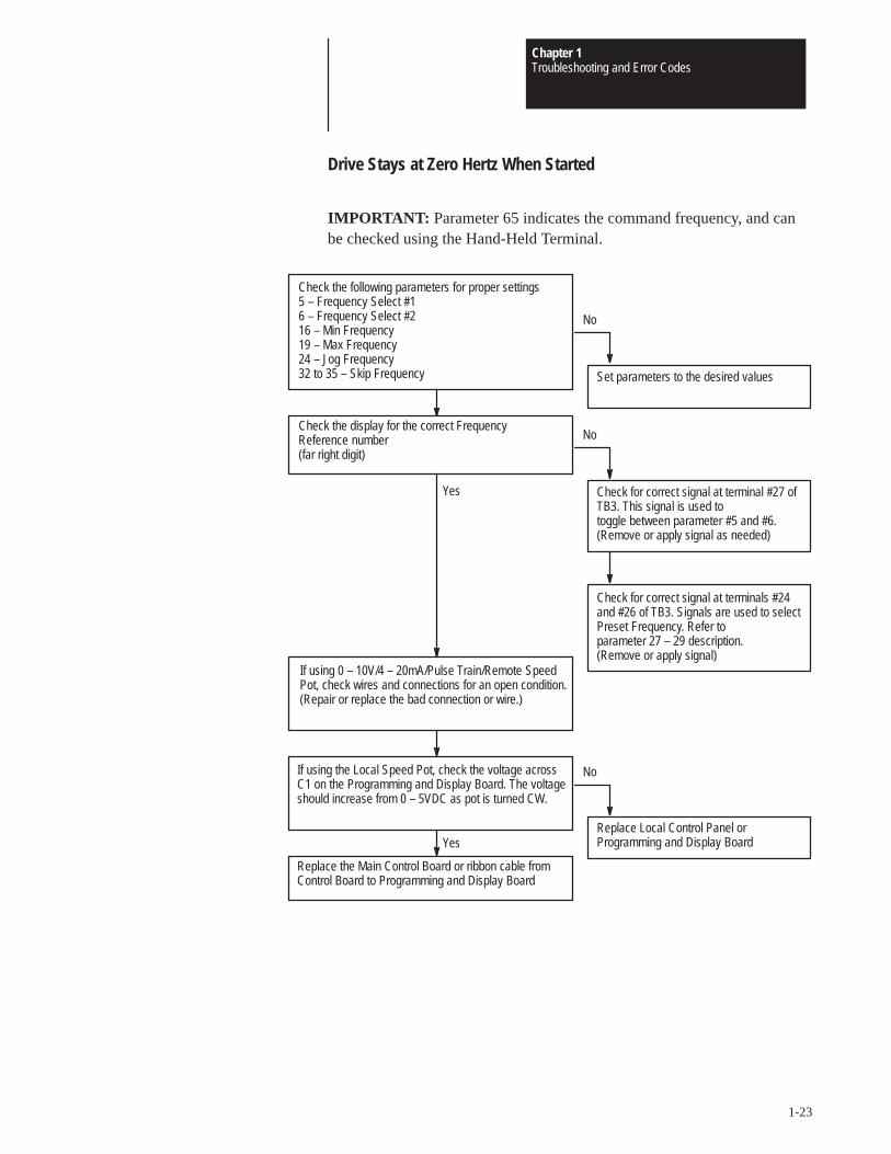
Drive Stays at Zero Hertz When Started
IMPORTANT: Parameter 65 indicates the command frequency, and canbe checked using the Hand-Held Terminal.
If using the Local Speed Pot, check the voltage acrossC1 on the Programming and Display Board. The voltageshould increase from 0 – 5VDC as pot is turned CW.
Check the following parameters for proper settings5 – Frequency Select #16 – Frequency Select #216 – Min Frequency19 – Max Frequency24 – Jog Frequency32 to 35 – Skip Frequency Set parameters to the desired values
If using 0 – 10V/4 – 20mA/Pulse Train/Remote SpeedPot, check wires and connections for an open condition.(Repair or replace the bad connection or wire.)
No
Check the display for the correct Frequency Reference number(far right digit)
No
No
Check for correct signal at terminal #27 ofTB3. This signal is used to toggle between parameter #5 and #6.(Remove or apply signal as needed)
Replace Local Control Panel or Programming and Display Board
Yes
Check for correct signal at terminals #24and #26 of TB3. Signals are used to selectPreset Frequency. Refer to parameter 27 – 29 description. (Remove or apply signal)
Replace the Main Control Board or ribbon cable fromControl Board to Programming and Display Board
Yes
Chapter 1Troubleshooting and Error Codes
1-24
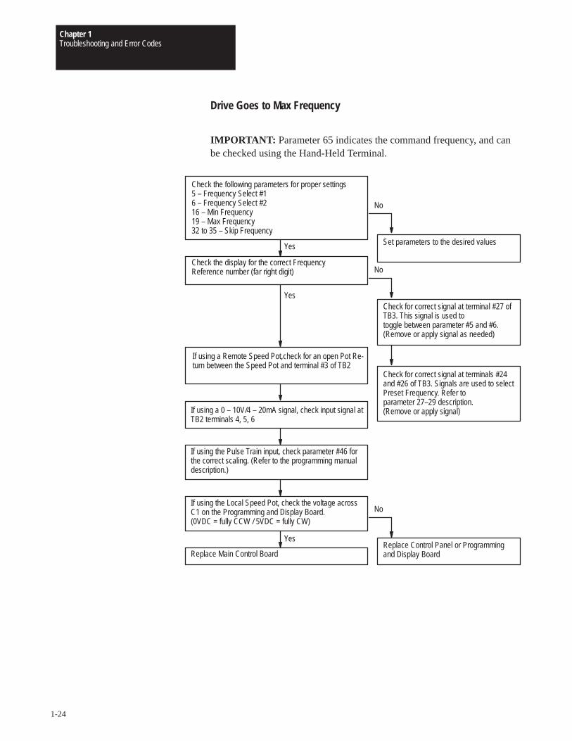
Drive Goes to Max Frequency
IMPORTANT: Parameter 65 indicates the command frequency, and canbe checked using the Hand-Held Terminal.
If using the Pulse Train input, check parameter #46 forthe correct scaling. (Refer to the programming manualdescription.)
If using a 0 – 10V/4 – 20mA signal, check input signal atTB2 terminals 4, 5, 6
Check the following parameters for proper settings5 – Frequency Select #16 – Frequency Select #216 – Min Frequency19 – Max Frequency32 to 35 – Skip Frequency
Set parameters to the desired values
If using a Remote Speed Pot,check for an open Pot Re-turn between the Speed Pot and terminal #3 of TB2
No
Check the display for the correct Frequency Reference number (far right digit)
No
No
Check for correct signal at terminal #27 ofTB3. This signal is used to toggle between parameter #5 and #6.(Remove or apply signal as needed)
Replace Control Panel or Programmingand Display Board
Yes
Check for correct signal at terminals #24and #26 of TB3. Signals are used to selectPreset Frequency. Refer to parameter 27–29 description. (Remove or apply signal)
Yes
If using the Local Speed Pot, check the voltage acrossC1 on the Programming and Display Board.(0VDC = fully CCW / 5VDC = fully CW)
Replace Main Control Board
Yes
Chapter 1Troubleshooting and Error Codes
1-25
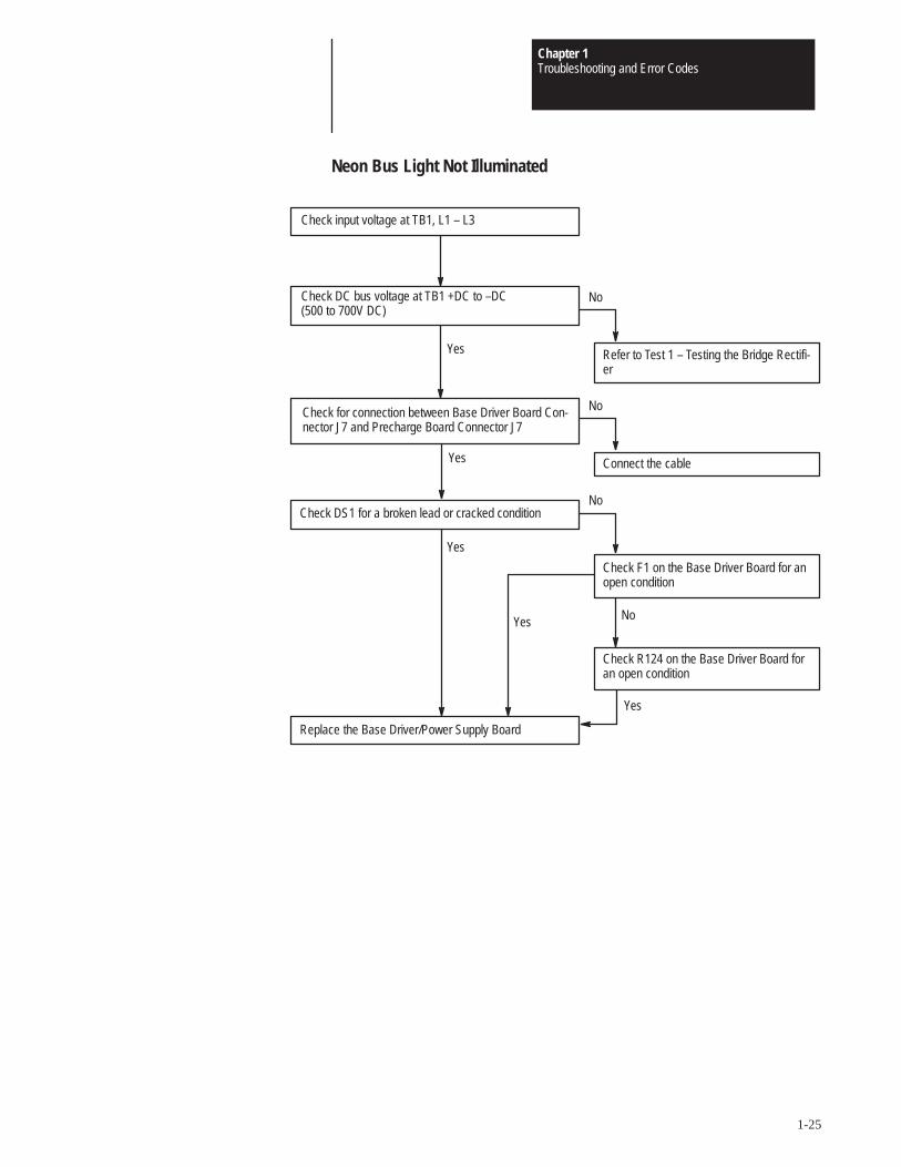
Neon Bus Light Not Illuminated
Replace the Base Driver/Power Supply Board
Check DS1 for a broken lead or cracked condition
Check input voltage at TB1, L1 – L3
Refer to Test 1 – Testing the Bridge Rectifi-er
Check for connection between Base Driver Board Con-nector J7 and Precharge Board Connector J7
NoCheck DC bus voltage at TB1 +DC to –DC(500 to 700V DC)
No
Connect the cable
Check R124 on the Base Driver Board foran open condition
Yes
Check F1 on the Base Driver Board for anopen condition
Yes
Yes
Yes
No
No
Yes
Chapter 1Troubleshooting and Error Codes
1-26
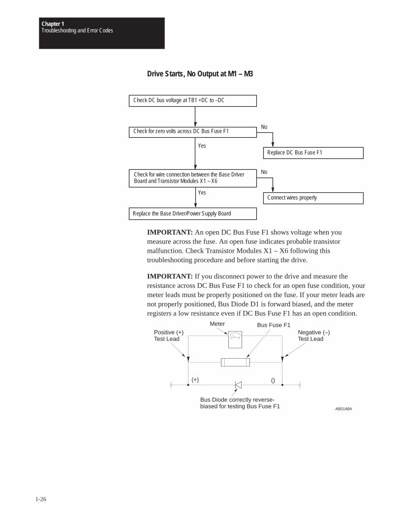
Drive Starts, No Output at M1 – M3
Replace the Base Driver/Power Supply Board
Check DC bus voltage at TB1 +DC to –DC
Replace DC Bus Fuse F1
Check for wire connection between the Base DriverBoard and Transistor Modules X1 – X6
NoCheck for zero volts across DC Bus Fuse F1
No
Connect wires properly
Yes
Yes
IMPORTANT: An open DC Bus Fuse F1 shows voltage when youmeasure across the fuse. An open fuse indicates probable transistormalfunction. Check Transistor Modules X1 – X6 following thistroubleshooting procedure and before starting the drive.
IMPORTANT: If you disconnect power to the drive and measure theresistance across DC Bus Fuse F1 to check for an open fuse condition, yourmeter leads must be properly positioned on the fuse. If your meter leads arenot properly positioned, Bus Diode D1 is forward biased, and the meterregisters a low resistance even if DC Bus Fuse F1 has an open condition.
Bus Diode correctly reverse-biased for testing Bus Fuse F1 AB0148A
Positive (+)Test Lead
Negative (–)Test Lead
(+) ()
Meter Bus Fuse F1
Chapter 1Troubleshooting and Error Codes
1-27
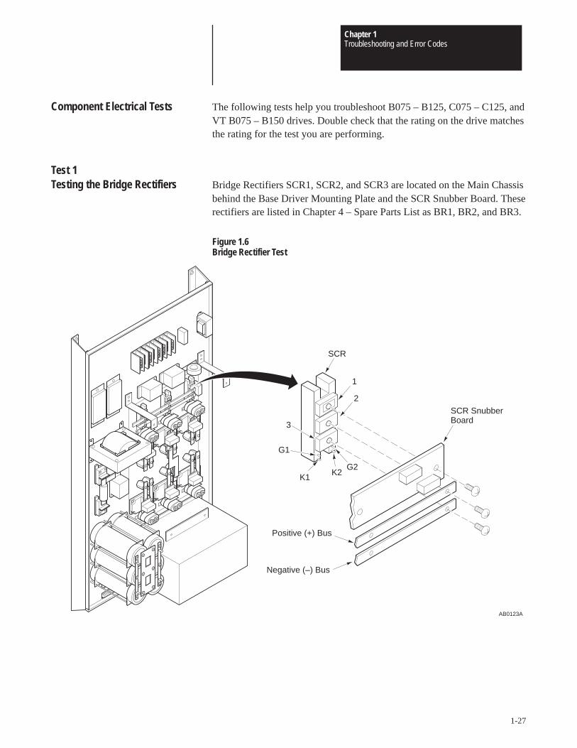
Component Electrical Tests The following tests help you troubleshoot B075 – B125, C075 – C125, andVT B075 – B150 drives. Double check that the rating on the drive matchesthe rating for the test you are performing.
Test 1 Testing the Bridge Rectifiers Bridge Rectifiers SCR1, SCR2, and SCR3 are located on the Main Chassis
behind the Base Driver Mounting Plate and the SCR Snubber Board. Theserectifiers are listed in Chapter 4 – Spare Parts List as BR1, BR2, and BR3.
Figure 1.6Bridge Rectifier Test
AB0123A
SCR
Negative (–) Bus
Positive (+) Bus
K1
G1
3
1
SCR SnubberBoard
2
G2K2
Chapter 1Troubleshooting and Error Codes
1-28
ATTENTION: Disconnect and lock out power from the drivebefore disassembling the drive. Failure to disconnect power mayresult in death or serious injury. A bus charge neon indicatorprovides visual indication that bus voltage is present. Verify busvoltage by measuring the voltage between +DC and –DC onTerminal Block TB1. Do not attempt to service the drive until theneon indicator has extinguished and the bus voltage has dischargedto zero volts.
IMPORTANT: Before you remove connections, bus bars, and wires fromthe drive components, mark the connections, bus bars, and wires tocorrespond with their component connections and terminals to preventincorrect wiring during assembly.
1. Remove power from the drive.
2. Wait for Bus Indicator Light DS1 to turn off before proceeding. Checkfor zero volts at TB1 Terminals +DC and –DC.
3. Remove the Base Driver Mounting Plate from the Drive. Refer toChapter 2 – Removing the Base Driver Mounting Plate.
4. Remove the SCR Snubber Board.
5. Remove the bridge rectifier bus bars.
6. Set your meter to test diodes.
7. Test each of the three bridge rectifiers. The following table shows meterconnections and ideal meter readings for those connections. Refer to theformer illustration for meter connection locations.
Meter (+) Lead Meter (–) Lead Nominal Meter Reading
1 2 Infinite3 1 Infinite
Table 1.BBridge Rectifier Test
Chapter 1Troubleshooting and Error Codes
1-29
8. Attach a 9V DC battery to an SCR:
a. Connect the positive battery lead to SCR Terminal G1
b. Connect the negative battery lead to SCR Terminal K1.
9. Set your meter to test diodes and test the SCR. Refer to the followingtable and former illustration for meter lead and SCR terminalconnections.
Meter (+) Lead Meter (–) Lead Nominal Meter Reading
1 2 0.88 Volts
Table 1.CRectifier Test with 9V DC at G1 and K1
10. Attach a 9V DC battery to an SCR:
a. Connect the positive battery lead to SCR Terminal G2.
b. Connect the negative battery lead to SCR Terminal K2.
c. Test the SCR with your meter set to test diodes. Refer to thefollowing table and former illustration for meter lead and SCRterminal connections.
Meter (+) Lead Meter (–) Lead Nominal Meter Reading
3 1 0.89 Volts
Table 1.DRectifier Test with 9V DC at G2 and K2
11. Replace any SCR producing readings other than those shown in theprevious table. Refer to Chapter 3 – SCR Modules.
Chapter 1Troubleshooting and Error Codes
1-30
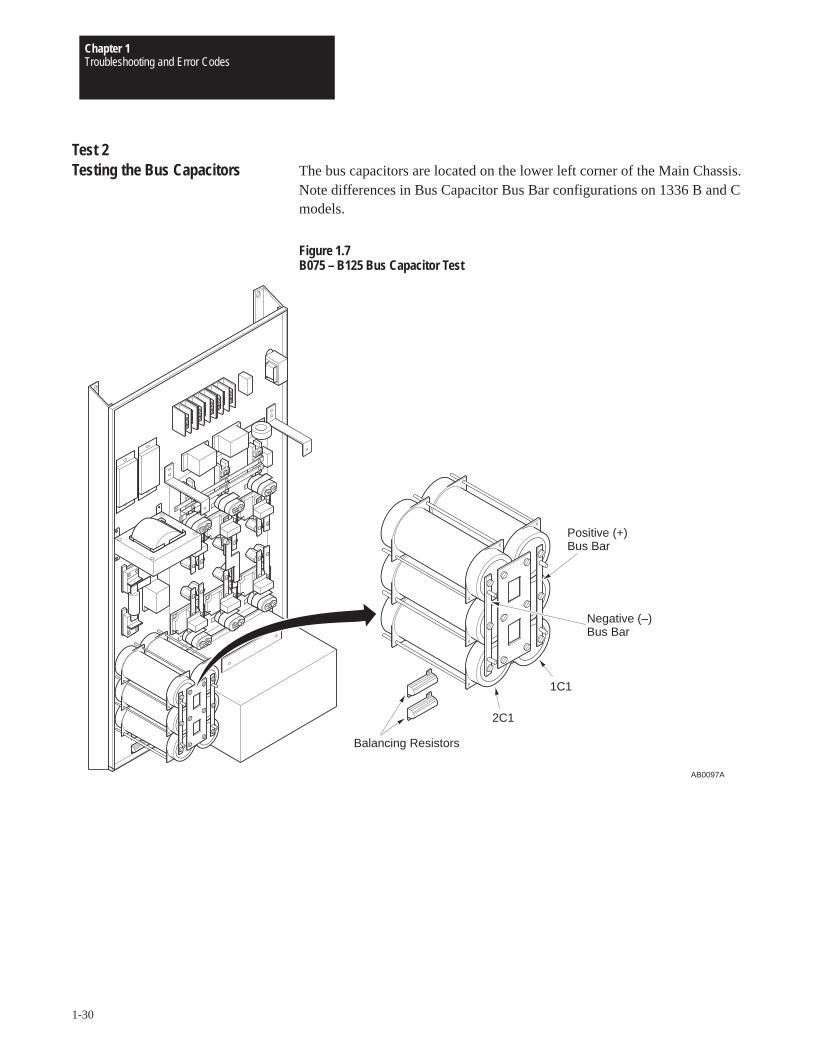
Test 2Testing the Bus Capacitors The bus capacitors are located on the lower left corner of the Main Chassis.
Note differences in Bus Capacitor Bus Bar configurations on 1336 B and Cmodels.
Figure 1.7B075 – B125 Bus Capacitor Test
AB0097A
Balancing Resistors
2C1
1C1
Positive (+)Bus Bar
Negative (–)Bus Bar
Chapter 1Troubleshooting and Error Codes
1-31
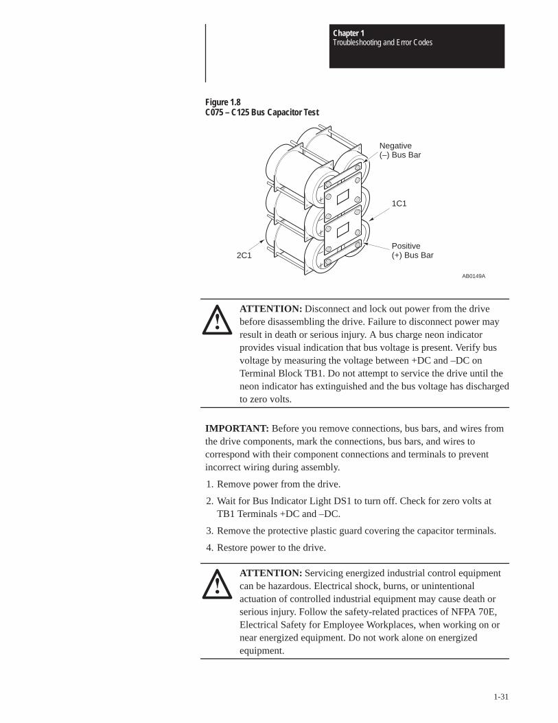
Figure 1.8C075 – C125 Bus Capacitor Test
Negative(–) Bus Bar
2C1
1C1
Positive(+) Bus Bar
AB0149A
ATTENTION: Disconnect and lock out power from the drivebefore disassembling the drive. Failure to disconnect power mayresult in death or serious injury. A bus charge neon indicatorprovides visual indication that bus voltage is present. Verify busvoltage by measuring the voltage between +DC and –DC onTerminal Block TB1. Do not attempt to service the drive until theneon indicator has extinguished and the bus voltage has dischargedto zero volts.
IMPORTANT: Before you remove connections, bus bars, and wires fromthe drive components, mark the connections, bus bars, and wires tocorrespond with their component connections and terminals to preventincorrect wiring during assembly.
1. Remove power from the drive.
2. Wait for Bus Indicator Light DS1 to turn off. Check for zero volts atTB1 Terminals +DC and –DC.
3. Remove the protective plastic guard covering the capacitor terminals.
4. Restore power to the drive.
ATTENTION: Servicing energized industrial control equipmentcan be hazardous. Electrical shock, burns, or unintentionalactuation of controlled industrial equipment may cause death orserious injury. Follow the safety-related practices of NFPA 70E,Electrical Safety for Employee Workplaces, when working on ornear energized equipment. Do not work alone on energizedequipment.
Chapter 1Troubleshooting and Error Codes
1-32
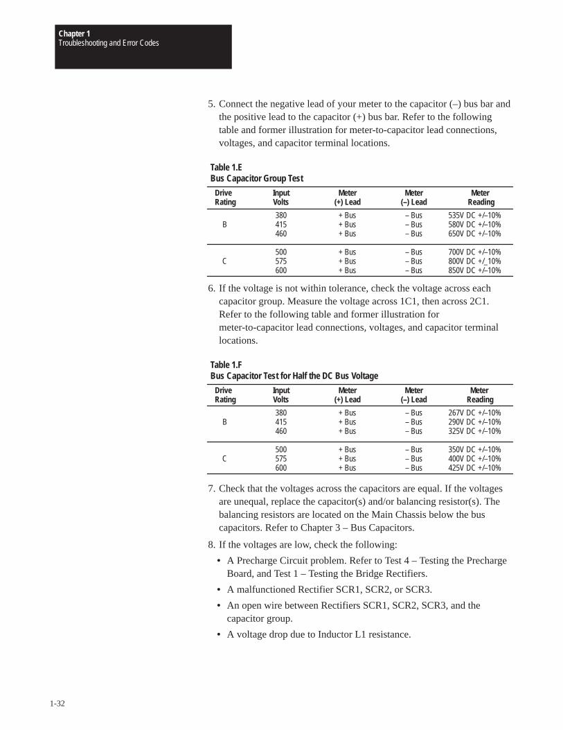
5. Connect the negative lead of your meter to the capacitor (–) bus bar andthe positive lead to the capacitor (+) bus bar. Refer to the followingtable and former illustration for meter-to-capacitor lead connections,voltages, and capacitor terminal locations.
Drive Input Meter Meter MeterRating Volts (+) Lead (–) Lead Reading
380 + Bus – Bus 535V DC +/–10%B 415 + Bus – Bus 580V DC +/–10%
460 + Bus – Bus 650V DC +/–10%
500 + Bus – Bus 700V DC +/–10%C 575 + Bus – Bus 800V DC +/_10%
600 + Bus – Bus 850V DC +/–10%
Table 1.EBus Capacitor Group Test
6. If the voltage is not within tolerance, check the voltage across eachcapacitor group. Measure the voltage across 1C1, then across 2C1.Refer to the following table and former illustration formeter-to-capacitor lead connections, voltages, and capacitor terminallocations.
Drive Input Meter Meter Meter Rating Volts (+) Lead (–) Lead Reading
380 + Bus – Bus 267V DC +/–10%B 415 + Bus – Bus 290V DC +/–10%
460 + Bus – Bus 325V DC +/–10%
500 + Bus – Bus 350V DC +/–10%C 575 + Bus – Bus 400V DC +/–10%
600 + Bus – Bus 425V DC +/–10%
Table 1.FBus Capacitor Test for Half the DC Bus Voltage
7. Check that the voltages across the capacitors are equal. If the voltagesare unequal, replace the capacitor(s) and/or balancing resistor(s). Thebalancing resistors are located on the Main Chassis below the buscapacitors. Refer to Chapter 3 – Bus Capacitors.
8. If the voltages are low, check the following:
• A Precharge Circuit problem. Refer to Test 4 – Testing the PrechargeBoard, and Test 1 – Testing the Bridge Rectifiers.
• A malfunctioned Rectifier SCR1, SCR2, or SCR3.
• An open wire between Rectifiers SCR1, SCR2, SCR3, and thecapacitor group.
• A voltage drop due to Inductor L1 resistance.
Chapter 1Troubleshooting and Error Codes
1-33
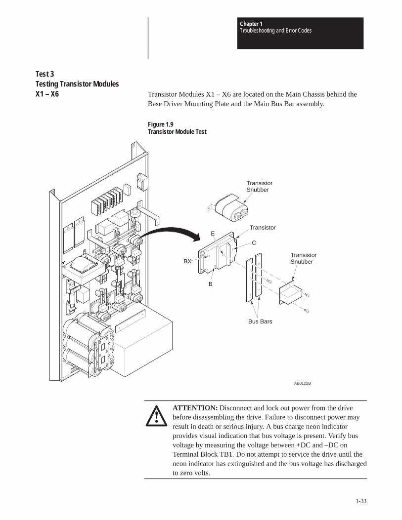
Test 3Testing Transistor Modules X1 – X6 Transistor Modules X1 – X6 are located on the Main Chassis behind the
Base Driver Mounting Plate and the Main Bus Bar assembly.
Figure 1.9Transistor Module Test
AB0122B
TransistorE
C
BX
B
TransistorSnubber
TransistorSnubber
Bus Bars
ATTENTION: Disconnect and lock out power from the drivebefore disassembling the drive. Failure to disconnect power mayresult in death or serious injury. A bus charge neon indicatorprovides visual indication that bus voltage is present. Verify busvoltage by measuring the voltage between +DC and –DC onTerminal Block TB1. Do not attempt to service the drive until theneon indicator has extinguished and the bus voltage has dischargedto zero volts.
Chapter 1Troubleshooting and Error Codes
1-34
IMPORTANT: Before you remove connections, bus bars, and wires fromthe drive components, mark the connections, bus bars, and wires tocorrespond with their component connections and terminals to preventincorrect wiring during assembly.
1. Remove power from the drive.
2. Wait for Bus Indicator Light DS1 to turn off before proceeding. Checkfor zero volts at TB1 Terminals +DC and –DC.
3. Remove the Main Bus Bar assembly. Refer to Chapter 2 – Removingthe Main Bus Bar Assembly.
4. Remove the wires from the transistor modules.
5. Remove the bus bars from the transistor modules.
6. Set your meter to test diodes.
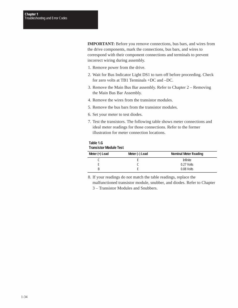
7. Test the transistors. The following table shows meter connections andideal meter readings for those connections. Refer to the formerillustration for meter connection locations.
Meter (+) Lead Meter (–) Lead Nominal Meter Reading
C E InfiniteE C 0.27 VoltsB E 0.08 Volts
Table 1.GTransistor Module Test
8. If your readings do not match the table readings, replace themalfunctioned transistor module, snubber, and diodes. Refer to Chapter3 – Transistor Modules and Snubbers.
Chapter 1Troubleshooting and Error Codes
1-35
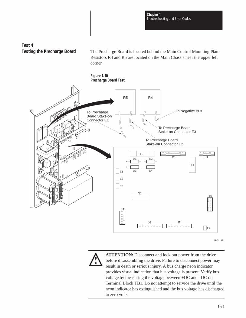
Test 4Testing the Precharge Board The Precharge Board is located behind the Main Control Mounting Plate.
Resistors R4 and R5 are located on the Main Chassis near the upper leftcorner.
Figure 1.10Precharge Board Test
AB0118B
To PrechargeBoard Stake-onConnector E1
F2
F1
E1
E2
E3
J5
E4
J3
J6 J7
D1 D2
D3 D4
+
+
Q1
J1J2
R4R5
To Precharge Board Stake-on Connector E2
To Precharge Board Stake-on Connector E3
To Negative Bus
ATTENTION: Disconnect and lock out power from the drivebefore disassembling the drive. Failure to disconnect power mayresult in death or serious injury. A bus charge neon indicatorprovides visual indication that bus voltage is present. Verify busvoltage by measuring the voltage between +DC and –DC onTerminal Block TB1. Do not attempt to service the drive until theneon indicator has extinguished and the bus voltage has dischargedto zero volts.
Chapter 1Troubleshooting and Error Codes
1-36
IMPORTANT: Before you remove connections, bus bars, and wires fromthe drive components, mark the connections, bus bars, and wires tocorrespond with their component connections and terminals to preventincorrect wiring during assembly.
1. Remove power from the drive.
2. Wait for Bus Indicator Light DS1 to turn off before proceeding. Checkfor zero volts at TB1 Terminals +DC and –DC.
3. Remove the Main Control Mounting Plate. Refer to Chapter 2 –Removing the Main Control Mounting Plate.
4. Remove the following from the Precharge Board:
• Connectors J1, J2, J3, J5, J6, and J7.
• Stake-on Connectors E1 – E4.
5. Set your meter to measure resistance.
6. Test the Precharge Board and Resistors R4 and R5. The following tableshows meter connections and ideal meter readings for testedcomponents. All values are nominal resistance in ohms. Refer to theformer illustration for meter connection locations.
Component Reading
Fuse F1 0 OhmsFuse F2 0 OhmsResistor R4 36 OhmsResistor R5 36 Ohms
Table 1.HPrecharge Board Test
7. If your readings match the table readings, continue to Step 8 in this test.If your readings do not match the table readings for:• Resistors R4 and R5, replace the resistors. Continue with Step 8 in
this test.• Fuses F1 or F2, replace the Precharge Board. Refer to Chapter
2 – Removing the Precharge Board.
8. Set your meter to test diodes.
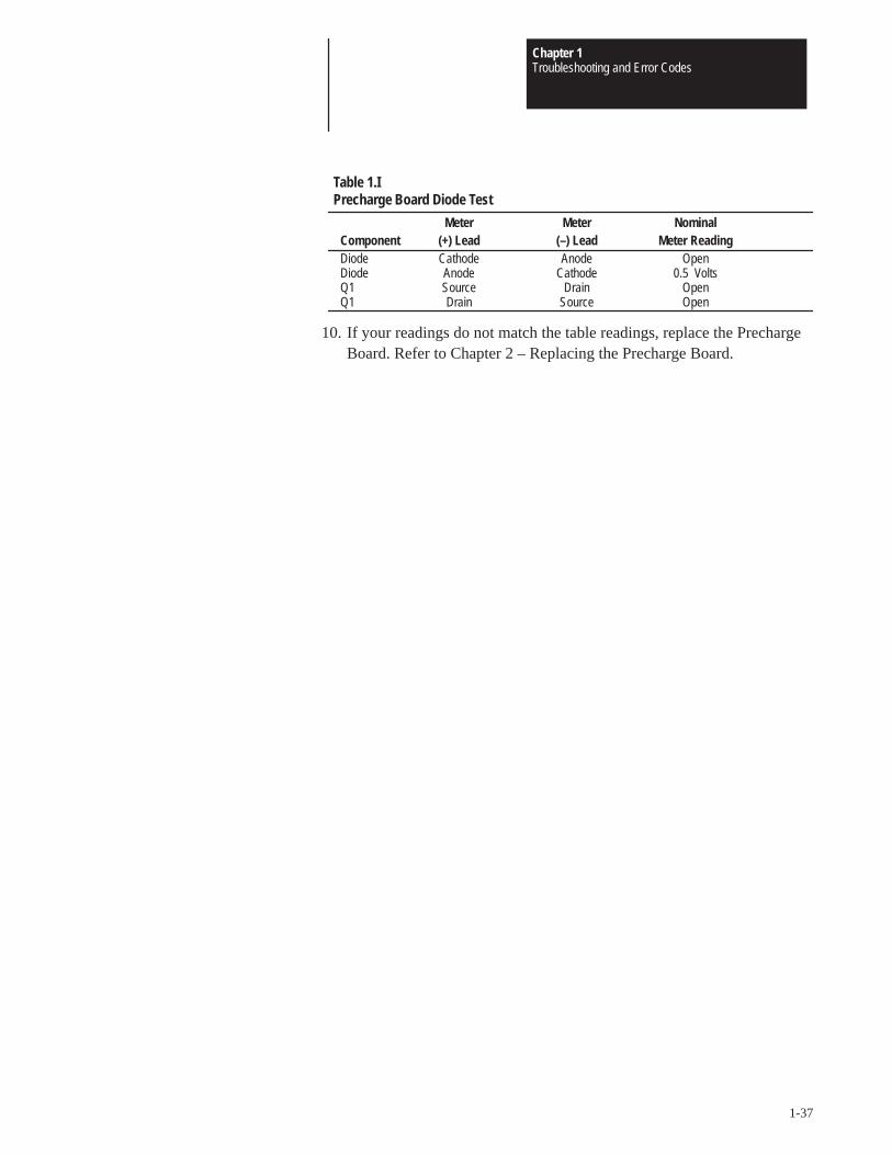
9. Test the Precharge Board diodes. The following table shows ideal meterreadings for tested components. Refer to the former illustration formeter connection locations.
Chapter 1Troubleshooting and Error Codes
1-37
Meter Meter NominalComponent (+) Lead (–) Lead Meter ReadingDiode Cathode Anode OpenDiode Anode Cathode 0.5 VoltsQ1 Source Drain OpenQ1 Drain Source Open
Table 1.IPrecharge Board Diode Test
10. If your readings do not match the table readings, replace the PrechargeBoard. Refer to Chapter 2 – Replacing the Precharge Board.
Chapter 1Troubleshooting and Error Codes
1-38
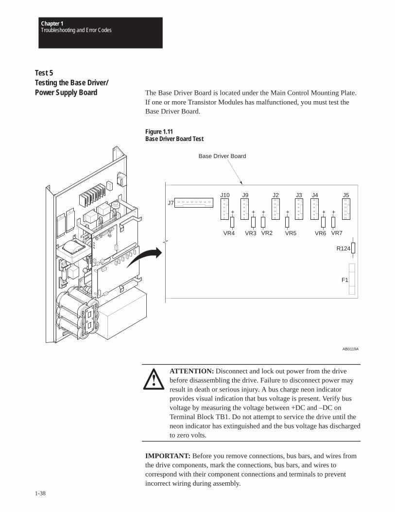
Test 5Testing the Base Driver/Power Supply Board The Base Driver Board is located under the Main Control Mounting Plate.
If one or more Transistor Modules has malfunctioned, you must test theBase Driver Board.
Figure 1.11Base Driver Board Test
AB0119A
F1
R124
VR7VR6VR5VR2
J5
VR3VR4
++++++
J4J3J2J9J10J7
Base Driver Board
ATTENTION: Disconnect and lock out power from the drivebefore disassembling the drive. Failure to disconnect power mayresult in death or serious injury. A bus charge neon indicatorprovides visual indication that bus voltage is present. Verify busvoltage by measuring the voltage between +DC and –DC onTerminal Block TB1. Do not attempt to service the drive until theneon indicator has extinguished and the bus voltage has dischargedto zero volts.
IMPORTANT: Before you remove connections, bus bars, and wires fromthe drive components, mark the connections, bus bars, and wires tocorrespond with their component connections and terminals to preventincorrect wiring during assembly.
Chapter 1Troubleshooting and Error Codes
1-39
1. Remove power from the drive.
2. Wait for Bus Indicator Light DS1 to turn off. Check for zero volts atTB1 Terminals +DC and –DC.
3. Remove the Main Control Mounting Plate. Refer to Chapter2 – Removing the Main Control Mounting Plate.
4. Remove Connectors J2 – J5, J9, and J10 from the Base Driver Board.
5. Set your meter to test diodes.
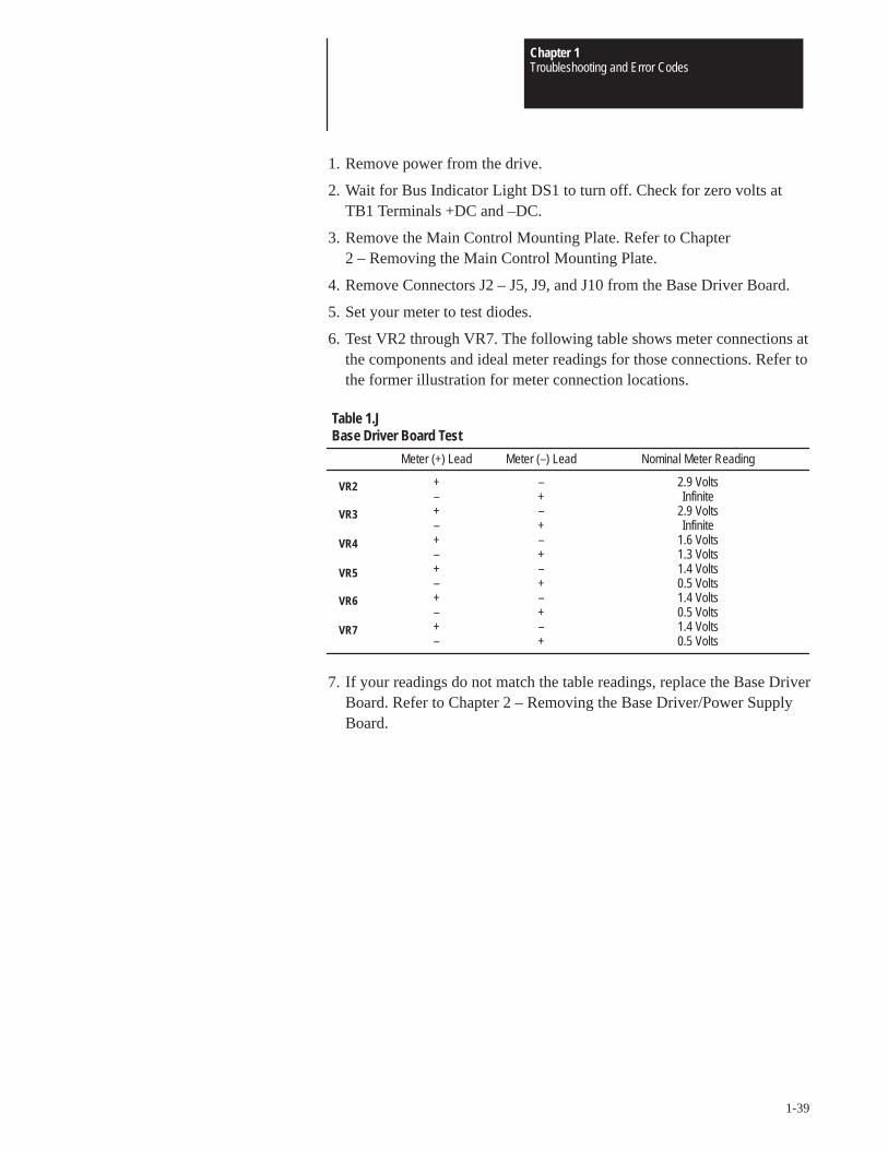
6. Test VR2 through VR7. The following table shows meter connections atthe components and ideal meter readings for those connections. Refer tothe former illustration for meter connection locations.
Meter (+) Lead Meter (–) Lead Nominal Meter Reading
+ – 2.9 Volts– + Infinite+ – 2.9 Volts– + Infinite+ – 1.6 Volts– + 1.3 Volts+ – 1.4 Volts– + 0.5 Volts+ – 1.4 Volts– + 0.5 Volts+ – 1.4 Volts– + 0.5 Volts
Table 1.JBase Driver Board Test
VR2
VR3
VR4
VR5
VR6
VR7
7. If your readings do not match the table readings, replace the Base DriverBoard. Refer to Chapter 2 – Removing the Base Driver/Power SupplyBoard.

Chapter 1Troubleshooting and Error Codes
1-40
This Page Intentionally Left Blank
ChapterChapter
2-1
Disassembly and Access Procedures
Chapter Objectives This chapter describes general disassembly procedures required to accessinternal drive components.
Disassembly and Access Overview
ATTENTION: Some printed circuit boards and drive componentsmay contain hazardous voltage levels. If neon light DS1 on theBase Driver Board is illuminated, hazardous voltages are present inthe drive circuit boards. Remove and lock out power before youdisconnect or reconnect wires, and before you remove or replacefuses and circuit boards. Verify bus voltage by measuring thevoltage between +DC and –DC on Terminal Block TB1. Do notattempt to service the drive until the neon indicator hasextinguished and the bus voltage has discharged to zero volts.
Electrostatic Discharge Precautions
ATTENTION: This assembly contains parts and sub-assembliesthat are sensitive to electrostatic discharge. Static controlprecautions are required when servicing this assembly. Componentdamage may result if you ignore electrostatic discharge controlprocedures. If you are not familiar with static control procedures,reference Allen-Bradley Publication 8000 – 4.5.2, GuardingAgainst Electrostatic Discharge, or any other applicable ESDprotection handbook.
Electrostatic discharge generated by static electricity can damage thecomplimentary metallic oxide semiconductor devices on various driveboards. It is recommended that you perform these procedures to guardagainst this type of damage when circuit boards are removed or installed:
• Wear a wrist type grounding strap that is grounded to the chassis.
• Attach the wrist strap before removing the new circuit board from theconductive packet.
• Remove boards from the drive and immediately insert them into theirconductive packets.
Chapter 2Disassembly and Access Procedures
2-2
Tools
You need the following tools to disassemble and assemble the drive:
• Pliers
• #1 Phillips screwdriver
• #2 Phillips screwdriver
• #3 Phillips screwdriver
• #4-5 standard screwdriver
• #8-10 standard screwdriver
• 3/8-inch or 9.6mm open-end wrench
• 11/16-inch or 17.5mm open-end wrench
• 3/8-inch or 9.6mm socket driver
• 9/16-inch or 15mm socket
• 7/16-inch or 11.5mm socket driver
• 3/16-inch or 4.8mm Allen wrench (B075, B100, C075, and C100Drives)
• 5/16-inch or 8mm Allen wrench (B125 and C125 Drives)
• Torque wrench, metered in lb-in. or N-m
Fastener Torque Specifications
Torque Sequence
When mounting components to a drive’s heat sink, component-fastenertorque sequences and tolerances are crucial to component-to-heat sink heatdissipation.
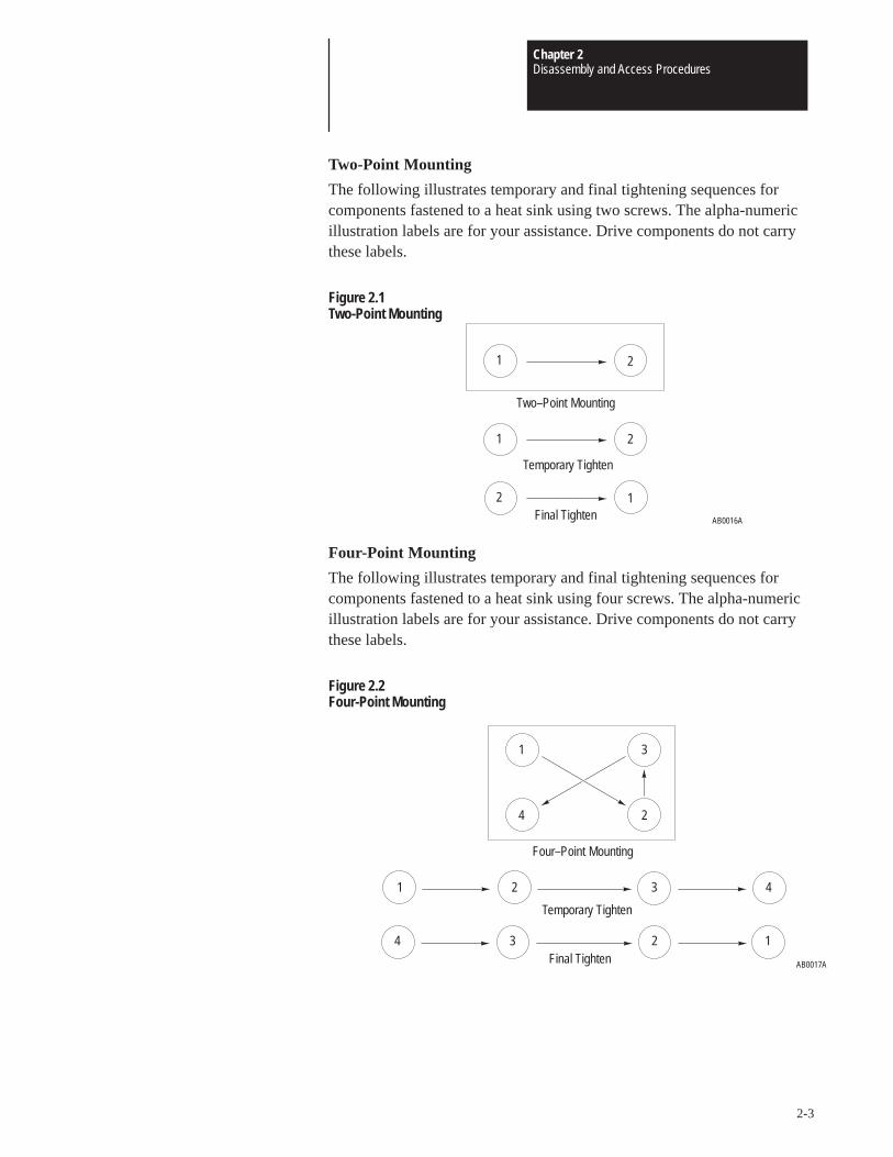
Chapter 2Disassembly and Access Procedures
2-3
Two-Point Mounting
The following illustrates temporary and final tightening sequences forcomponents fastened to a heat sink using two screws. The alpha-numericillustration labels are for your assistance. Drive components do not carrythese labels.
Figure 2.1Two-Point Mounting
21
AB0016A
12
21
Temporary Tighten
Final Tighten
Two–Point Mounting
Four-Point Mounting
The following illustrates temporary and final tightening sequences forcomponents fastened to a heat sink using four screws. The alpha-numericillustration labels are for your assistance. Drive components do not carrythese labels.
Figure 2.2Four-Point Mounting
AB0017A
1
2
3
4
1 32 4
4 123
Temporary Tighten
Final Tighten
Four–Point Mounting
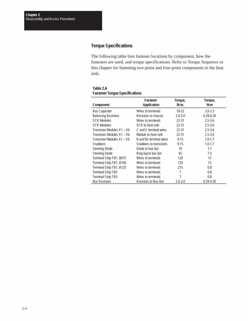
Chapter 2Disassembly and Access Procedures
2-4
Torque Specifications
The following table lists fastener locations by component, how thefasteners are used, and torque specifications. Refer to Torque Sequence inthis chapter for fastening two-point and four-point components to the heatsink.
Fastener Torque, Torque,Component Application lb-in. N-m
Bus Capacitor Wires to terminals 18-22 2.0-2.5Balancing Resistors Resistors to chassis 2.6-3.0 0.29-0.30SCR Modules Wires to terminals 22-31 2.5-3.6SCR Modules SCR to heat sink 22-31 2.5-3.6Transistor Modules X1 – X6 C and E terminal wires 22-31 2.5-3.6Transistor Modules X1 – X6 Module to heat sink 22-31 2.5-3.6Transistor Modules X1 – X6 B and Bx terminal wires 9-15 1.0-1.7Snubbers Snubbers to transistors 9-15 1.0-1.7Steering Diode Diode to bus bar 10 1.1Steering Diode Ring lug to bus bar 65 7.3Terminal Strip TB1, B075 Wires to terminals 120 13Terminal Strip TB1, B100 Wires to terminals 120 13Terminal Strip TB1, B125 Wires to terminals 275 0.8Terminal Strip TB2 Wires to terminals 7 0.8Terminal Strip TB3 Wires to terminals 7 0.8Bus Resistors Resistors to Bus Bar 2.6-3.0 0.29-0.30
Table 2.AFastener Torque Specifications
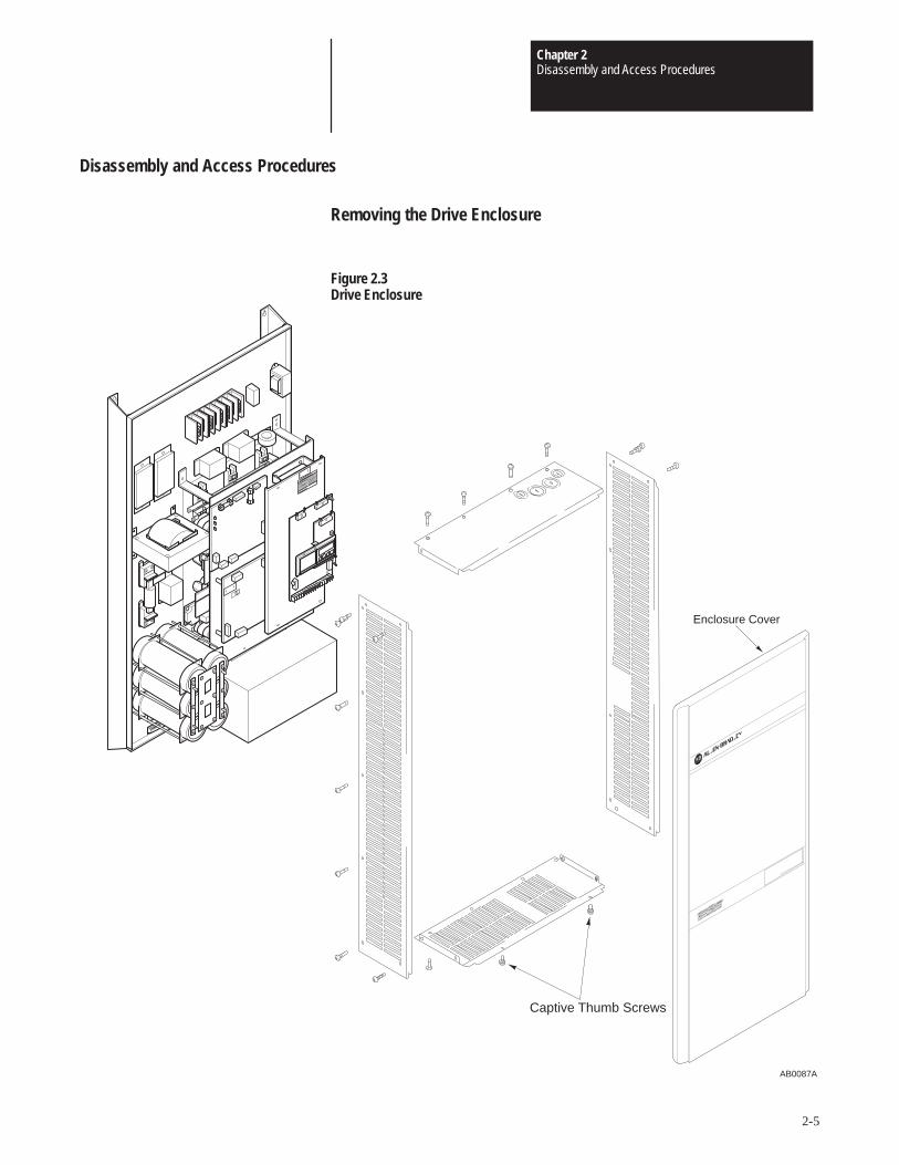
Chapter 2Disassembly and Access Procedures
2-5
Disassembly and Access Procedures
Removing the Drive Enclosure
Figure 2.3Drive Enclosure
Captive Thumb Screws
Enclosure Cover
AB0087A
Chapter 2Disassembly and Access Procedures
2-6
Removal
ATTENTION: Disconnect and lock out power from the drivebefore disassembling the drive. Failure to disconnect power mayresult in death or serious injury. A bus charge neon indicatorprovides visual indication that bus voltage is present. Verify busvoltage by measuring the voltage between +DC and –DC onTerminal Block TB1. Do not attempt to service the drive until theneon indicator has extinguished and the bus voltage has dischargedto zero volts.
ATTENTION: Wear a wrist-type grounding strap when servicing1336 Drives. Failure to protect drive components against ESD maydamage drive components. Refer to Electrostatic DischargePrecautions at the beginning of this chapter.
1. Remove power from the drive.
2. Remove the captive thumb screw fastening the Enclosure cover to thebottom of the Enclosure frame.
3. Pull the bottom of the cover outward to clear the Enclosure frame, thenlift the cover upward to remove the cover.
4. Remove the screws from the Enclosure frame side panels.
5. Remove the screws from the Enclosure frame top and bottom panels.
6. Wait for Bus Indicator Light DS1 to turn off before proceeding withinternal component disassembly. Check for zero volts at TB1 Terminals+DC and –DC.
Installation
Install the Enclosure in reverse order of removal.
ATTENTION: Replace all guards before applying power to thedrive. Failure to replace guards may result in death or seriousinjury.
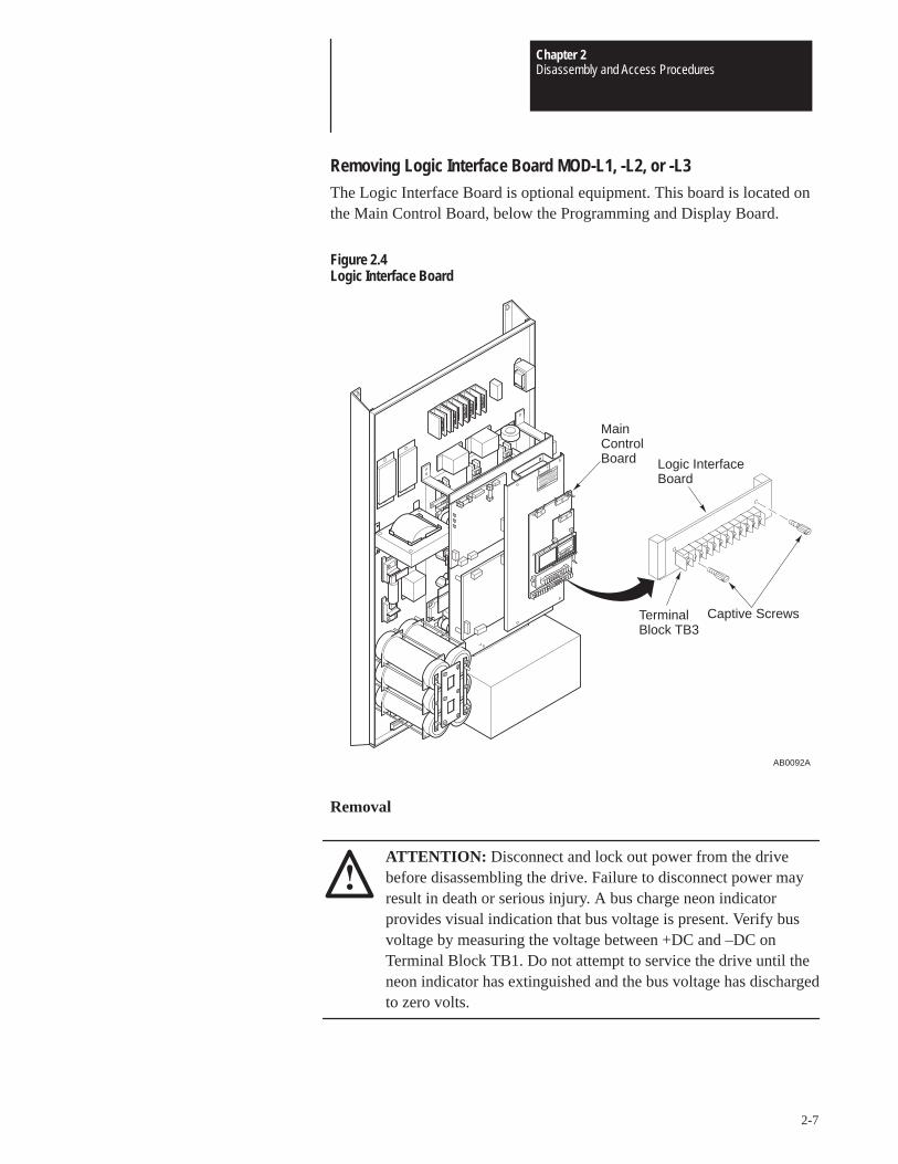
Chapter 2Disassembly and Access Procedures
2-7
Removing Logic Interface Board MOD-L1, -L2, or -L3The Logic Interface Board is optional equipment. This board is located onthe Main Control Board, below the Programming and Display Board.
Figure 2.4Logic Interface Board
AB0092A
Logic InterfaceBoard
Captive ScrewsTerminalBlock TB3
Main ControlBoard
Removal
ATTENTION: Disconnect and lock out power from the drivebefore disassembling the drive. Failure to disconnect power mayresult in death or serious injury. A bus charge neon indicatorprovides visual indication that bus voltage is present. Verify busvoltage by measuring the voltage between +DC and –DC onTerminal Block TB1. Do not attempt to service the drive until theneon indicator has extinguished and the bus voltage has dischargedto zero volts.
Chapter 2Disassembly and Access Procedures
2-8
ATTENTION: Wear a wrist-type grounding strap when servicing1336 Drives. Failure to protect drive components against ESD maydamage drive components. Refer to Electrostatic DischargePrecautions at the beginning of this chapter.
IMPORTANT: Before you remove connections, bus bars, and wires fromthe drive components, mark the connections, bus bars, and wires tocorrespond with their component connections and terminals to preventincorrect wiring during assembly.
1. Remove power from the drive. Check for zero volts at TB1 Terminals+DC and –DC.
2. Remove the Enclosure cover if the drive has an enclosure. Refer toRemoving the Drive Enclosure in this chapter.
3. Remove all wires from the terminals on TB3.
4. Loosen the two captive screws fastening the Logic Interface Board tothe Main Control Board Connectors J8 and J9.
5. Grip the right and left sides of the Logic Interface Board and pull theboard straight outward from the Main Control Board.
Installation
Install the Logic Interface Board in reverse order of removal.
ATTENTION: Replace all guards before applying power to thedrive. Failure to replace guards may result in death or seriousinjury.
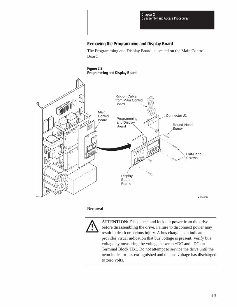
Chapter 2Disassembly and Access Procedures
2-9
Removing the Programming and Display BoardThe Programming and Display Board is located on the Main ControlBoard.
Figure 2.5Programming and Display Board
AB0093B
Flat-HandScrews
Ribbon Cablefrom Main ControlBoard
Connector J1Programmingand DisplayBoard Round-Head
Screw
DisplayBoard Frame
MainControlBoard
Removal
ATTENTION: Disconnect and lock out power from the drivebefore disassembling the drive. Failure to disconnect power mayresult in death or serious injury. A bus charge neon indicatorprovides visual indication that bus voltage is present. Verify busvoltage by measuring the voltage between +DC and –DC onTerminal Block TB1. Do not attempt to service the drive until theneon indicator has extinguished and the bus voltage has dischargedto zero volts.
Chapter 2Disassembly and Access Procedures
2-10
ATTENTION: Wear a wrist-type grounding strap when servicing1336 Drives. Failure to protect drive components against ESD maydamage drive components. Refer to Electrostatic DischargePrecautions at the beginning of this chapter.
IMPORTANT: Before you remove connections, bus bars, and wires fromthe drive components, mark the connections, bus bars, and wires tocorrespond with their component connections and terminals to preventincorrect wiring during assembly.
1. Remove power from the drive. Check for zero volts at TB1 Terminals+DC and –DC.
2. Remove the Enclosure cover if the drive has an enclosure. Refer toRemoving the Drive Enclosure in this chapter.
3. Remove the ribbon cable from Display Board Connector J1.
4. Remove the flat-head screws from the four corners of the grey DisplayBoard frame.
5. Remove the round-head screw from the Display Board’s printed circuitboard.
6. Remove the Programming and Display Board from the Main ControlBoard.
Installation
Install the Programming and Display Board in reverse order of removal.
ATTENTION: Replace all guards before applying power to thedrive. Failure to replace guards may result in death or seriousinjury.
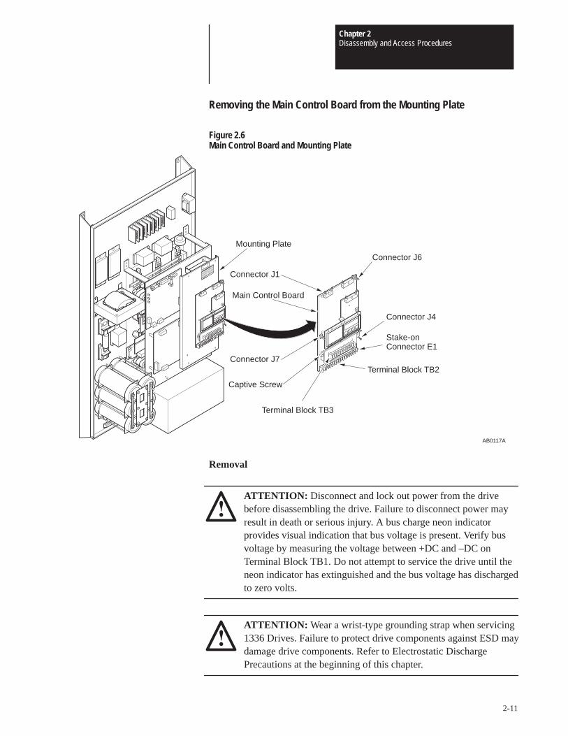
Chapter 2Disassembly and Access Procedures
2-11
Removing the Main Control Board from the Mounting Plate
Figure 2.6Main Control Board and Mounting Plate
AB0117A
Connector J1
Mounting Plate
Connector J6
Connector J4
Stake-onConnector E1
Terminal Block TB2Connector J7
Main Control Board
Terminal Block TB3
Captive Screw
Removal
ATTENTION: Disconnect and lock out power from the drivebefore disassembling the drive. Failure to disconnect power mayresult in death or serious injury. A bus charge neon indicatorprovides visual indication that bus voltage is present. Verify busvoltage by measuring the voltage between +DC and –DC onTerminal Block TB1. Do not attempt to service the drive until theneon indicator has extinguished and the bus voltage has dischargedto zero volts.
ATTENTION: Wear a wrist-type grounding strap when servicing1336 Drives. Failure to protect drive components against ESD maydamage drive components. Refer to Electrostatic DischargePrecautions at the beginning of this chapter.
Chapter 2Disassembly and Access Procedures
2-12
IMPORTANT: Before you remove connections, bus bars, and wires fromthe drive components, mark the connections, bus bars, and wires tocorrespond with their component connections and terminals to preventincorrect wiring during assembly.
1. Remove power from the drive. Check for zero volts at TB1 Terminals+DC and –DC.
2. Remove the Enclosure cover if the drive has an enclosure. Refer toRemoving the Drive Enclosure in this chapter.
3. Remove the Logic Interface Board and the Programming and DisplayBoard. Refer to Removing the Logic Interface Board and Removing theProgramming and Display Board procedures in this chapter.
4. Disconnect the following from the Main Control Board:
• J1 ribbon cable
• J6 connector
• J7 connector
• E1 stake-on connector
• J4 ribbon cable connector, if MOD-S1 is used
• All wires from the TB2 terminals
5. Remove the two captive screws fastening the Main Control Board to theMounting Plate. These screws are located near Main Control BoardConnectors J8 and J9.
6. Turn the six standoff screws 1/4 turn counterclockwise.
7. Pull the Main Control Board away from the standoffs.
Installation
Install the Main Control Board in reverse order of removal.
ATTENTION: Replace all guards before applying power to thedrive. Failure to replace guards may result in death or seriousinjury.
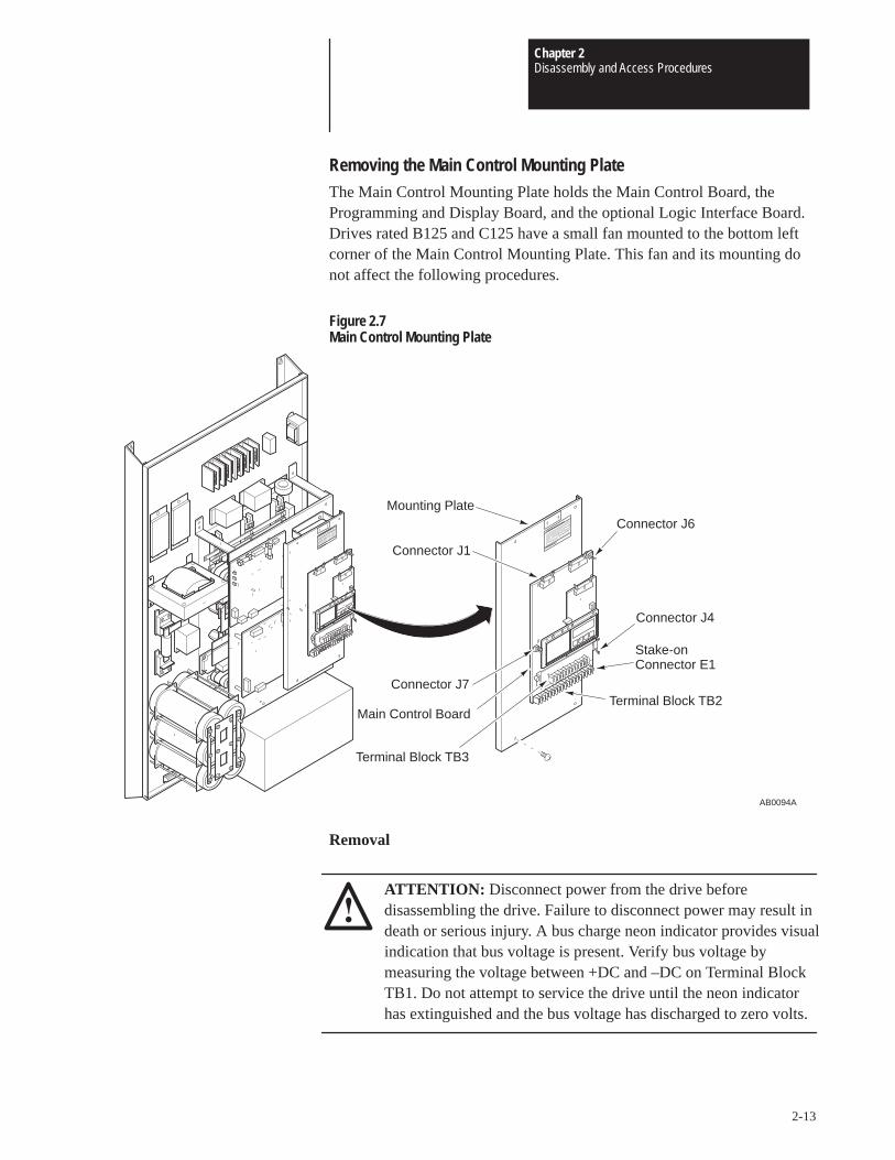
Chapter 2Disassembly and Access Procedures
2-13
Removing the Main Control Mounting PlateThe Main Control Mounting Plate holds the Main Control Board, theProgramming and Display Board, and the optional Logic Interface Board.Drives rated B125 and C125 have a small fan mounted to the bottom leftcorner of the Main Control Mounting Plate. This fan and its mounting donot affect the following procedures.
Figure 2.7Main Control Mounting Plate
AB0094A
Connector J6
Connector J4
Stake-onConnector E1
Terminal Block TB2
Connector J1
Mounting Plate
Connector J7
Main Control Board
Terminal Block TB3
Removal
ATTENTION: Disconnect power from the drive beforedisassembling the drive. Failure to disconnect power may result indeath or serious injury. A bus charge neon indicator provides visualindication that bus voltage is present. Verify bus voltage bymeasuring the voltage between +DC and –DC on Terminal BlockTB1. Do not attempt to service the drive until the neon indicatorhas extinguished and the bus voltage has discharged to zero volts.
Chapter 2Disassembly and Access Procedures
2-14
ATTENTION: Wear a wrist-type grounding strap when servicing1336 Drives. Failure to protect drive components against ESD maydamage drive components. Refer to Electrostatic DischargePrecautions at the beginning of this chapter.
IMPORTANT: Before you remove connections, bus bars, and wires fromthe drive components, mark the connections, bus bars, and wires tocorrespond with their component connections and terminals to preventincorrect wiring during assembly.
1. Remove power from the drive.
2. Remove the Enclosure cover from the drive. Refer to Removing theDrive Enclosure in this chapter.
3. Wait for Bus Indicator Light DS1 to turn off. Check for zero volts atTB1 Terminals +DC and –DC before proceeding.
4. Remove the three screws fastening the plastic guard to the Base Driverand Main Control Mounting Plates.
5. Remove the plastic guard from the snap-on connection at the bottom leftcorner of the guard.
6. Remove the following from the Main Control Board:
• J1 ribbon cable
• J6 connector
• J7 connector
• E1 stake-on connector
• J4 ribbon cable connector if MOD-S1 is used
• All wires from TB2 terminals
7. Remove all wires from the TB3 terminals if a Logic Interface Board isbeing used.
8. Remove the two screws fastening the right side of Main ControlMounting Plate to the drive.
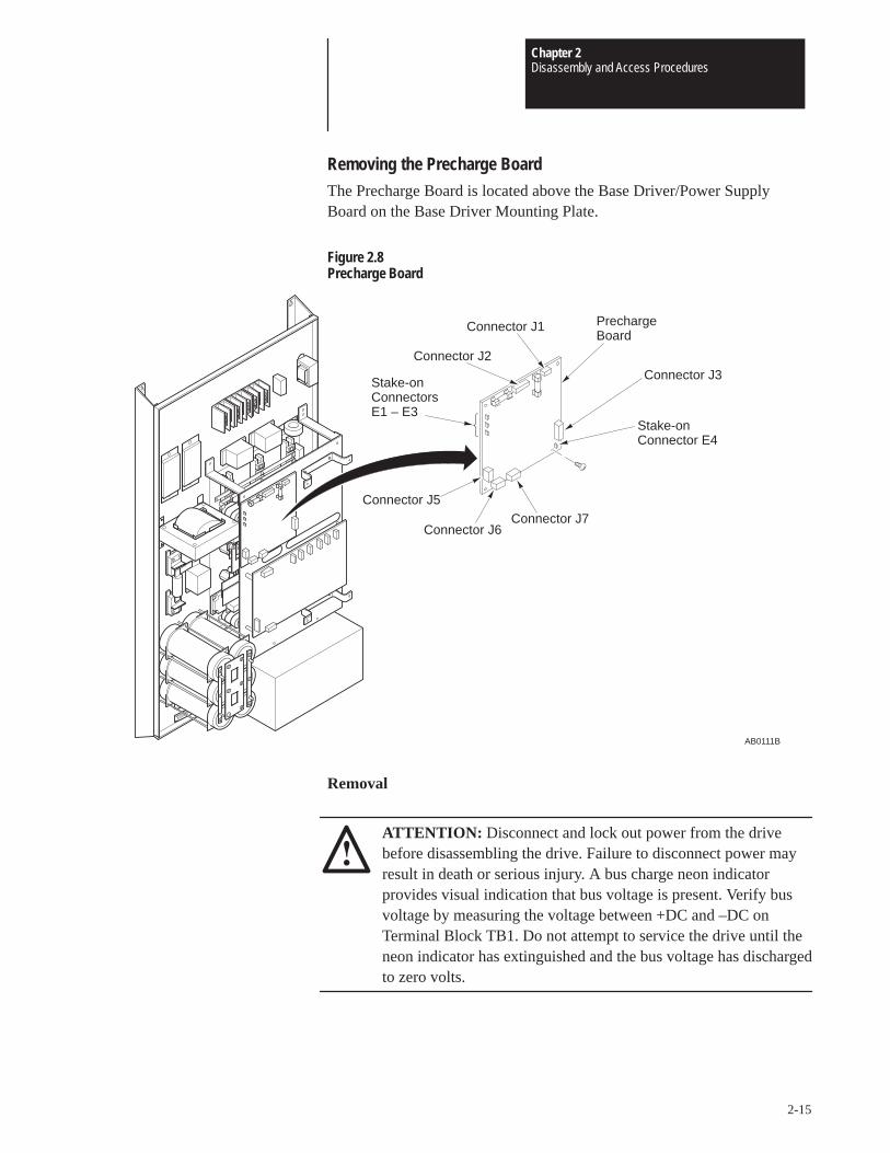
Chapter 2Disassembly and Access Procedures
2-15
Removing the Precharge BoardThe Precharge Board is located above the Base Driver/Power SupplyBoard on the Base Driver Mounting Plate.
Figure 2.8Precharge Board
Stake-onConnectorsE1 – E3
AB0111B
Connector J3
Stake-onConnector E4
Connector J7Connector J6
Precharge Board
Connector J2
Connector J1
Connector J5
Removal
ATTENTION: Disconnect and lock out power from the drivebefore disassembling the drive. Failure to disconnect power mayresult in death or serious injury. A bus charge neon indicatorprovides visual indication that bus voltage is present. Verify busvoltage by measuring the voltage between +DC and –DC onTerminal Block TB1. Do not attempt to service the drive until theneon indicator has extinguished and the bus voltage has dischargedto zero volts.

Chapter 2Disassembly and Access Procedures
2-16
ATTENTION: Wear a wrist-type grounding strap when servicing1336 Drives. Failure to protect drive components against ESD maydamage drive components. Refer to Electrostatic DischargePrecautions at the beginning of this chapter.
IMPORTANT: Before you remove connections, bus bars, and wires fromthe drive components, mark the connections, bus bars, and wires tocorrespond with their component connections and terminals to preventincorrect wiring during assembly. Where connectors pass through accessholes in mounting plates, mark the holes to correspond with the connectorsthat pass through the holes.
1. Remove the Main Control Mounting Plate from the drive. Refer toRemoving the Main Control Mounting Plate in this chapter.
2. Disconnect the following from the Precharge Board:
• J1 through J3 connectors
• J5 through J7 connectors
• E1 through E4 wires at the stake-on connectors.
3. Remove the standoff from the upper left corner of the Precharge Board.
4. Remove the three screws from the remaining corners of the PrechargeBoard.
5. Turn the two standoff screws on the Precharge Board 1/4 turncounterclockwise.
6. Pull the Precharge Board away from the standoffs.
Installation
Install the Precharge Board in reverse order of removal.
ATTENTION: Replace all guards before applying power to thedrive. Failure to replace guards may result in death or seriousinjury.
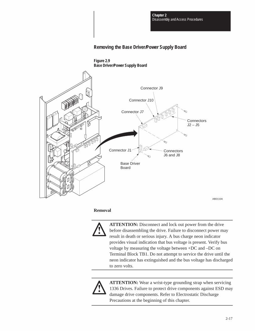
Chapter 2Disassembly and Access Procedures
2-17
Removing the Base Driver/Power Supply Board
Figure 2.9Base Driver/Power Supply Board
ConnectorsJ6 and J8
AB0110A
Connector J9
Connector J10
Base DriverBoard
Connector J7
Connector J1
ConnectorsJ2 – J5
Removal
ATTENTION: Disconnect and lock out power from the drivebefore disassembling the drive. Failure to disconnect power mayresult in death or serious injury. A bus charge neon indicatorprovides visual indication that bus voltage is present. Verify busvoltage by measuring the voltage between +DC and –DC onTerminal Block TB1. Do not attempt to service the drive until theneon indicator has extinguished and the bus voltage has dischargedto zero volts.
ATTENTION: Wear a wrist-type grounding strap when servicing1336 Drives. Failure to protect drive components against ESD maydamage drive components. Refer to Electrostatic DischargePrecautions at the beginning of this chapter.
Chapter 2Disassembly and Access Procedures
2-18
IMPORTANT: Before you remove connections, bus bars, and wires fromthe drive components, mark the connections, bus bars, and wires tocorrespond with their component connections and terminals to preventincorrect wiring during assembly. Where connectors pass through accessholes in mounting plates, mark the holes to correspond with the connectorsthat pass through the holes.
1. Remove power from the drive. Wait for Bus Indicator Light DS1 to turnoff before proceeding.
2. Remove the Main Control Mounting Plate from the drive. Refer toRemoving the Main Control Mounting Plate in this chapter.
3. Remove Connectors J2 through J10 from the Base Driver Board.
4. Remove the four screws fastening the Base Driver Board to the BaseDriver Mounting Plate. These screws are located at the corners of theBase Driver Board.
5. Turn the four standoff screws 1/4 turn counterclockwise.
6. Pull the Base Driver Board away from the standoffs.
Installation
Install the Base Driver/Power Supply Board in reverse order of removal.
ATTENTION: Replace all guards before applying power to thedrive. Failure to replace guards may result in death or seriousinjury.
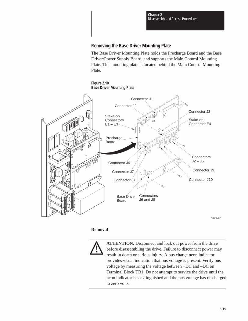
Chapter 2Disassembly and Access Procedures
2-19
Removing the Base Driver Mounting PlateThe Base Driver Mounting Plate holds the Precharge Board and the BaseDriver/Power Supply Board, and supports the Main Control MountingPlate. This mounting plate is located behind the Main Control MountingPlate.
Figure 2.10Base Driver Mounting Plate
AB0099A
Connector J3
Stake-onConnector E4
ConnectorsJ2 – J5
Connector J9
Connector J10
ConnectorsJ6 and J8
Base DriverBoard
Connector J7
Connector J7
Connector J6
Precharge Board
Stake-onConnectorsE1 – E3
Connector J2
Connector J1
Removal
ATTENTION: Disconnect and lock out power from the drivebefore disassembling the drive. Failure to disconnect power mayresult in death or serious injury. A bus charge neon indicatorprovides visual indication that bus voltage is present. Verify busvoltage by measuring the voltage between +DC and –DC onTerminal Block TB1. Do not attempt to service the drive until theneon indicator has extinguished and the bus voltage has dischargedto zero volts.
Chapter 2Disassembly and Access Procedures
2-20
ATTENTION: Wear a wrist-type grounding strap when servicing1336 Drives. Failure to protect drive components against ESD maydamage drive components. Refer to Electrostatic DischargePrecautions at the beginning of this chapter.
IMPORTANT: Before you remove connections, bus bars, and wires fromthe drive components, mark the connections, bus bars, and wires tocorrespond with their component connections and terminals to preventincorrect wiring during assembly. Where connectors pass through accessholes in mounting plates, mark the holes to correspond with the connectorsthat pass through the holes.
1. Remove the Main Control Mounting Plate from the drive. Refer toRemoving the Main Control Mounting Plate in this chapter.
2. Remove Connectors J2 – J5 and J7 – J10 from the Base Driver Board.
3. Remove the following from the Precharge Board:
• J1 – J3 connectors
• J6 and J7 connectors
• E1 – E4 wires at the stake-on connectors
4. Remove the four screws fastening the Base Driver Mounting Plate to thedrive.
Installation
Install the Base Driver Mounting Plate in reverse order of removal.
ATTENTION: Replace all guards before applying power to thedrive. Failure to replace guards may result in death or seriousinjury.
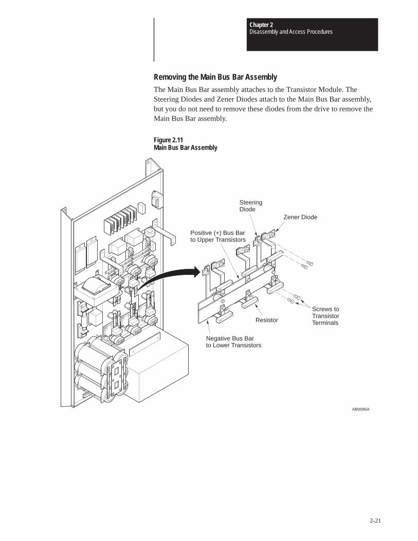
Chapter 2Disassembly and Access Procedures
2-21
Removing the Main Bus Bar AssemblyThe Main Bus Bar assembly attaches to the Transistor Module. TheSteering Diodes and Zener Diodes attach to the Main Bus Bar assembly,but you do not need to remove these diodes from the drive to remove theMain Bus Bar assembly.
Figure 2.11Main Bus Bar Assembly
AB0095A
Screws toTransistorTerminalsResistor
Negative Bus Barto Lower Transistors
Positive (+) Bus Barto Upper Transistors
Zener Diode
SteeringDiode
Chapter 2Disassembly and Access Procedures
2-22
Removal
ATTENTION: Disconnect and lock out power from the drivebefore disassembling the drive. Failure to disconnect power mayresult in death or serious injury. A bus charge neon indicatorprovides visual indication that bus voltage is present. Verify busvoltage by measuring the voltage between +DC and –DC onTerminal Block TB1. Do not attempt to service the drive until theneon indicator has extinguished and the bus voltage has dischargedto zero volts.
ATTENTION: Wear a wrist-type grounding strap when servicing1336 Drives. Failure to protect drive components against ESD maydamage drive components. Refer to Electrostatic DischargePrecautions at the beginning of this chapter.
IMPORTANT: Before you remove connections, bus bars, and wires fromthe drive components, mark the connections, bus bars, and wires tocorrespond with their component connections and terminals to preventincorrect wiring during assembly.
1. Remove the Base Driver Mounting Plate from the drive. Refer toRemoving the Base Driver Mounting Plate in this chapter.
2. Remove the Bus Resistor wires from the Bus Snubber stake-onconnectors.
3. Remove the screws fastening the two wires to the Main Bus Bars. Thewire on the upper negative bus bar comes from the Bus Capacitor group,and the wire on the lower positive bus bar comes from Bus Fuse F1.
4. Remove the screws fastening the Main Bus Bar assembly to theTransistor Module.
5. Remove the screws fastening the M1, M2, and M3 wires to the MainBus Bar assembly.
6. Remove the Main Bus Bar assembly from the drive.
Installation
Install the Main Bus Bar assembly in reverse order of removal.
ATTENTION: Replace all guards before applying power to thedrive. Failure to replace guards may result in death or seriousinjury.

Chapter 2Disassembly and Access Procedures
2-23
Accessing Chassis To access the power components located on the chassis, refer to RemovingPower Components the Base Driver Mounting Plate, Removing the Main Control Mounting
Plate, and Removing the Main Bus Bar Assembly in this chapter.

Chapter 2Disassembly and Access Procedures
2-24
This Page Intentionally Left Blank
Chapter
3-1
Part Replacement Procedures
Chapter Objective This chapter describes procedures required to replace drive components.This chapter references Chapter 2 – Disassembly and Access Proceduresfor basic drive component access.
Part Replacement Overview The part replacement procedures in this chapter assume that the drive youare servicing either has no enclosure or that the enclosure is removed fromthe drive. For more information on removing the Drive Enclosure, refer toChapter 2 – Disassembly and Access Procedures, Removing the DriveEnclosure.
Safety Precautions
ATTENTION: Some printed circuit boards and drive componentsmay contain hazardous voltage levels. If Bus Indicator neon lightDS1 on the Base Driver Board is illuminated, hazardous voltagesare present in the drive circuit boards. Remove power before youdisconnect or reconnect wires, and before you remove or replacefuses and circuit boards. Verify bus voltage by measuring thevoltage between +DC and –DC on Terminal Block TB1. Do notattempt to service the drive until the neon indicator hasextinguished and the bus voltage has discharged to zero volts.
Electrostatic Discharge Precautions
ATTENTION: This assembly contains parts and sub-assembliesthat are sensitive to electrostatic discharge. Static controlprecautions are required when servicing this assembly. Componentdamage may result if you ignore electrostatic discharge controlprocedures. If you are not familiar with static control procedures,reference Allen-Bradley Publication 8000 – 4.5.2, GuardingAgainst Electrostatic Discharge, or any other applicable ESDprotection handbook.
Chapter 3Part Replacement Procedures
3-2
Electrostatic discharge generated by static electricity can damage thecomplimentary metallic oxide semiconductor devices on various driveboards. It is recommended that you perform these procedures to guardagainst this type of damage when circuit boards are removed or installed:
• Wear a wrist type grounding strap that is grounded to the chassis.
• Attach the wrist strap before removing the new circuit board from theconductive packet.
• Remove boards from the drive and immediately insert them into theirconductive packets.
Tools
You need the following tools to disassemble and assemble the drive:
• Pliers
• #1 Phillips screwdriver
• #2 Phillips screwdriver
• #3 Phillips screwdriver
• #4-5 standard screwdriver
• #8-10 standard screwdriver
• 3/8-inch or 9.6mm open-end wrench
• 11/16-inch or 17.5mm open-end wrench
• 3/8-inch or 9.6mm socket driver
• 7/16-inch or 11.5mm socket driver
• 3/16-inch or 4.8mm Allen wrench (B075, B100, C075, and C100Drives)
• 5/16-inch or 8mm Allen wrench (B125 and C125 Drives)
• Torque wrench, metered in lb-in. or N-m
• Wire-terminal crimping tool
Fastener Torque Specifications
Torque Sequence
When mounting components to a drive’s heat sink, component fastenertorque sequences and tolerances are crucial to component-to-heat sink heatdissipation.
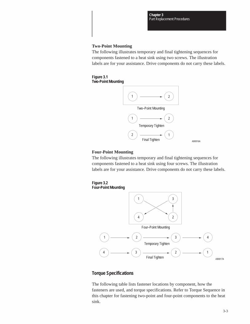
Chapter 3Part Replacement Procedures
3-3
Two-Point MountingThe following illustrates temporary and final tightening sequences forcomponents fastened to a heat sink using two screws. The illustrationlabels are for your assistance. Drive components do not carry these labels.
Figure 3.1Two-Point Mounting
21
AB0016A
12
21
Temporary Tighten
Final Tighten
Two–Point Mounting
Four-Point MountingThe following illustrates temporary and final tightening sequences forcomponents fastened to a heat sink using four screws. The illustrationlabels are for your assistance. Drive components do not carry these labels.
Figure 3.2Four-Point Mounting
AB0017A
1
2
3
4
1 32 4
4 123
Temporary Tighten
Final Tighten
Four–Point Mounting
Torque Specifications
The following table lists fastener locations by component, how thefasteners are used, and torque specifications. Refer to Torque Sequence inthis chapter for fastening two-point and four-point components to the heatsink.
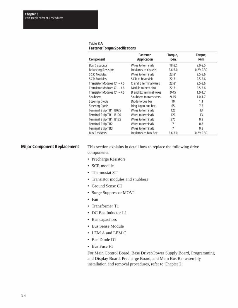
Chapter 3Part Replacement Procedures
3-4
Fastener Torque, Torque,Component Application lb-in. N-m
Bus Capacitor Wires to terminals 18-22 2.0-2.5Balancing Resistors Resistors to chassis 2.6-3.0 0.29-0.30SCR Modules Wires to terminals 22-31 2.5-3.6SCR Modules SCR to heat sink 22-31 2.5-3.6Transistor Modules X1 – X6 C and E terminal wires 22-31 2.5-3.6Transistor Modules X1 – X6 Module to heat sink 22-31 2.5-3.6Transistor Modules X1 – X6 B and Bx terminal wires 9-15 1.0-1.7Snubbers Snubbers to transistors 9-15 1.0-1.7Steering Diode Diode to bus bar 10 1.1Steering Diode Ring lug to bus bar 65 7.3Terminal Strip TB1, B075 Wires to terminals 120 13Terminal Strip TB1, B100 Wires to terminals 120 13Terminal Strip TB1, B125 Wires to terminals 275 0.8Terminal Strip TB2 Wires to terminals 7 0.8Terminal Strip TB3 Wires to terminals 7 0.8Bus Resistors Resistors to Bus Bar 2.6-3.0 0.29-0.30
Table 3.AFastener Torque Specifications
Major Component Replacement This section explains in detail how to replace the following drivecomponents:
• Precharge Resistors
• SCR module
• Thermostat ST
• Transistor modules and snubbers
• Ground Sense CT
• Surge Suppressor MOV1
• Fan
• Transformer T1
• DC Bus Inductor L1
• Bus capacitors
• Bus Sense Module
• LEM A and LEM C
• Bus Diode D1
• Bus Fuse F1
For Main Control Board, Base Driver/Power Supply Board, Programmingand Display Board, Precharge Board, and Main Bus Bar assemblyinstallation and removal procedures, refer to Chapter 2.
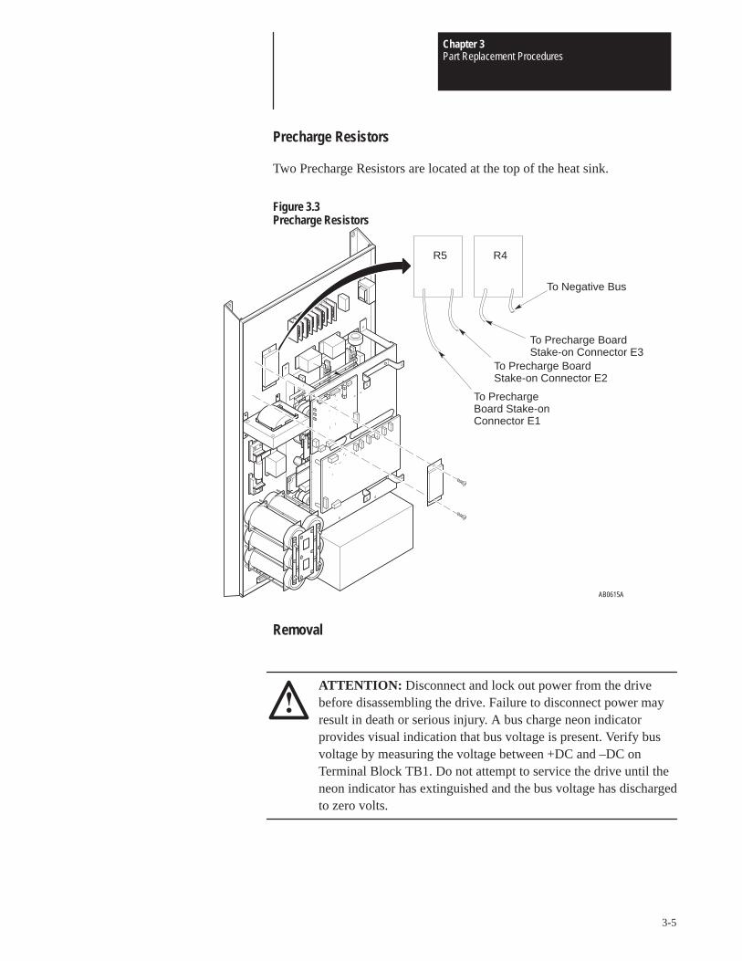
Chapter 3Part Replacement Procedures
3-5
Precharge Resistors
Two Precharge Resistors are located at the top of the heat sink.
Figure 3.3Precharge Resistors
AB0615A
To PrechargeBoard Stake-onConnector E1
R4R5
To Precharge Board Stake-on Connector E2
To Precharge Board Stake-on Connector E3
To Negative Bus
Removal
ATTENTION: Disconnect and lock out power from the drivebefore disassembling the drive. Failure to disconnect power mayresult in death or serious injury. A bus charge neon indicatorprovides visual indication that bus voltage is present. Verify busvoltage by measuring the voltage between +DC and –DC onTerminal Block TB1. Do not attempt to service the drive until theneon indicator has extinguished and the bus voltage has dischargedto zero volts.

Chapter 3Part Replacement Procedures
3-6
ATTENTION: Wear a wrist-type grounding strap when servicing1336 Drives. Failure to protect drive components against ESD maydamage drive components. Refer to Electrostatic DischargePrecautions at the beginning of this chapter.
IMPORTANT: Before you remove connections, bus bars, and wires fromthe drive components, mark the connections, bus bars, and wires tocorrespond with their component connections and terminals to preventincorrect wiring during assembly.
1. Remove power from the drive.
2. Wait for the Bus Indicator Light DS1 to turn off. Check for zero volts atTB1 Terminals +DC and –DC before proceeding.
3. Remove the two screws fastening the Precharge Resistor to the heatsink.
4. Remove the Precharge Resistor wires from the following:
• Precharge Board stake-on connectors
• Negative Bus (R4 only)
Installation
1. Clean the surfaces between the Precharge Resistor and the heat sink.
2. Install the Precharge Resistor in reverse order of removal.
ATTENTION: Replace all guards before applying power to thedrive. Failure to replace guards may result in death or seriousinjury.
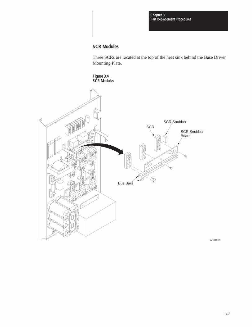
Chapter 3Part Replacement Procedures
3-7
SCR Modules
Three SCRs are located at the top of the heat sink behind the Base DriverMounting Plate.
Figure 3.4SCR Modules
SCR Snubber
AB0101B
Bus Bars
SCR
Board
SCR Snubber
Chapter 3Part Replacement Procedures
3-8
Removal
ATTENTION: Disconnect and lock out power from the drivebefore disassembling the drive. Failure to disconnect power mayresult in death or serious injury. A bus charge neon indicatorprovides visual indication that bus voltage is present. Verify busvoltage by measuring the voltage between +DC and –DC onTerminal Block TB1. Do not attempt to service the drive until theneon indicator has extinguished and the bus voltage has dischargedto zero volts.
ATTENTION: Wear a wrist-type grounding strap when servicing1336 Drives. Failure to protect drive components against ESD maydamage drive components. Refer to Electrostatic DischargePrecautions at the beginning of this chapter.
IMPORTANT: Before you remove connections, bus bars, and wires fromthe drive components, mark the connections, bus bars, and wires tocorrespond with their component connections and terminals to preventincorrect wiring during assembly.
1. Remove power from the drive.
2. Wait for Bus Indicator Light DS1 to turn off. Check for zero volts atTB1 Terminals +DC and –DC before proceeding.
3. Remove the Base Driver Mounting Plate from the drive. Refer toChapter 2 – Removing the Base Driver Mounting Plate.
4. Remove the three screws fastening the SCR Snubber Board to the #1terminals on the SCRs.
5. Remove the standoffs fastening the L1, L2, and L3 wires to the #1terminals of the SCRs.
6. Remove the wires from the malfunctioned SCR Stake-on connectors.
7. Remove the screws fastening the bus bars to the SCR terminals.
8. Remove the screw fastening the SCR Snubber to the heat sink. Thissnubber is located to the right of the SCRs.
9. Remove the screws fastening the malfunctioned SCR to the heat sink.
Chapter 3Part Replacement Procedures
3-9
Installation
1. Clean the surfaces between the SCR and the heat sink.
2. Replace the Preform between the SCR and the heat sink.
3. Install SCR in reverse order of removal. Always replace the SCRsnubbers when replacing an SCR.
IMPORTANT: When installing the SCR Snubber Board, fasten thefollowing Snubber Board leads to the following wires, located at the SCRterminals:
• A∅ to L1
• B∅ to L2
• C∅ to L3The wire from TB1, Terminal L1 connects to SCR1, Terminal 1; L2 toSCR2, Terminal 1; and L3 to SCR3, Terminal 1.
ATTENTION: Replace all guards before applying power to thedrive. Failure to replace guards may result in death or seriousinjury.
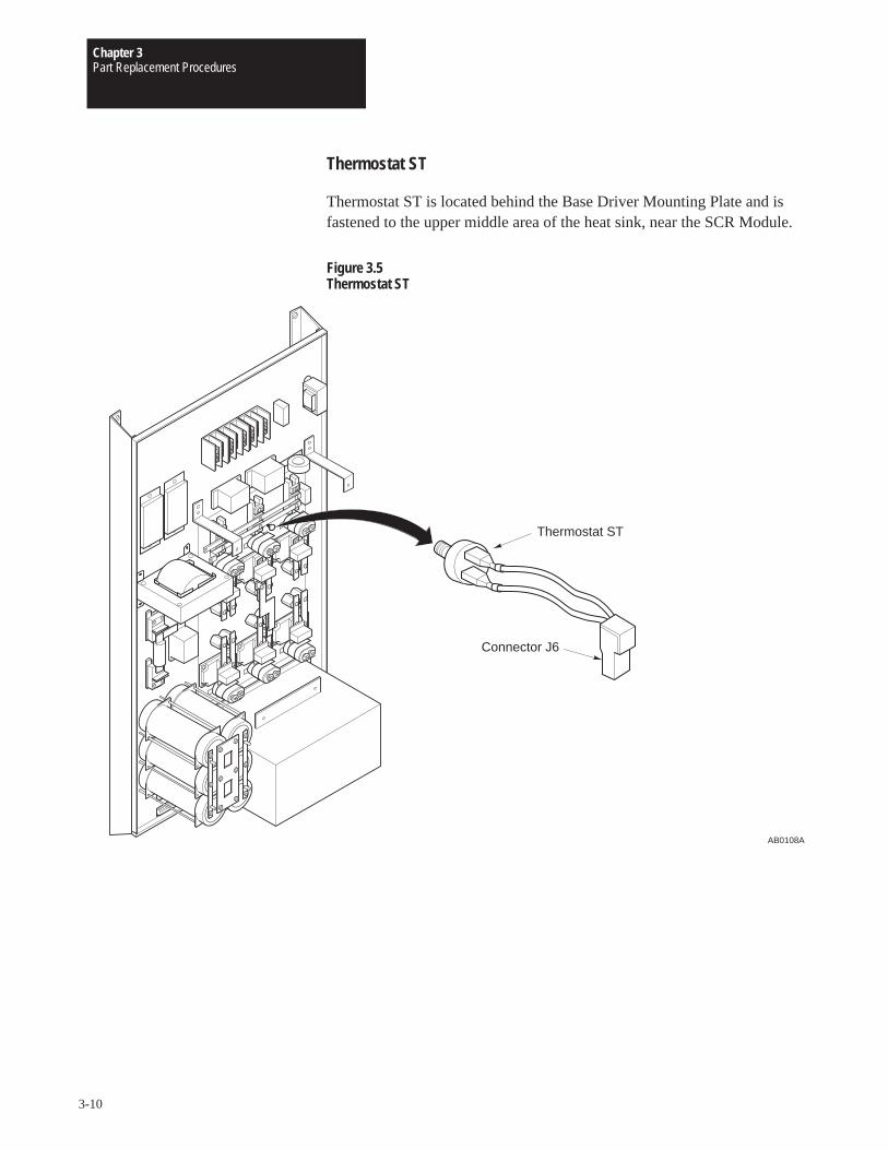
Chapter 3Part Replacement Procedures
3-10
Thermostat ST
Thermostat ST is located behind the Base Driver Mounting Plate and isfastened to the upper middle area of the heat sink, near the SCR Module.
Figure 3.5Thermostat ST
Connector J6
AB0108A
Thermostat ST
Chapter 3Part Replacement Procedures
3-11
Removal
ATTENTION: Disconnect and lock out power from the drivebefore disassembling the drive. Failure to disconnect power mayresult in death or serious injury. A bus charge neon indicatorprovides visual indication that bus voltage is present. Verify busvoltage by measuring the voltage between +DC and –DC onTerminal Block TB1. Do not attempt to service the drive until theneon indicator has extinguished and the bus voltage has dischargedto zero volts.
ATTENTION: Wear a wrist-type grounding strap when servicing1336 Drives. Failure to protect drive components against ESD maydamage drive components. Refer to Electrostatic DischargePrecautions at the beginning of this chapter.
IMPORTANT: Before you remove connections, bus bars, and wires fromthe drive components, mark the connections, bus bars, and wires tocorrespond with their component connections and terminals to preventincorrect wiring during assembly.
1. Remove power from the drive.
2. Wait for Bus Indicator Light DS1 to turn off. Check for zero volts atTB1 Terminals +DC and –DC before proceeding.
3. Remove the Base Driver Mounting Plate from the drive. Refer toChapter 2 – Removing the Base Driver Mounting Plate.
4. Remove the two wires from the Thermostat ST stake-on connectors.
5. Unscrew the thermostat from the heat sink.
Installation
Install Thermostat ST1 in reverse order of removal.
IMPORTANT: When fastening the thermostat to the heat sink,hand-tighten the thermostat to avoid damaging the porcelain thermostatbody.
ATTENTION: Replace all guards before applying power to thedrive. Failure to replace guards may result in death or seriousinjury.
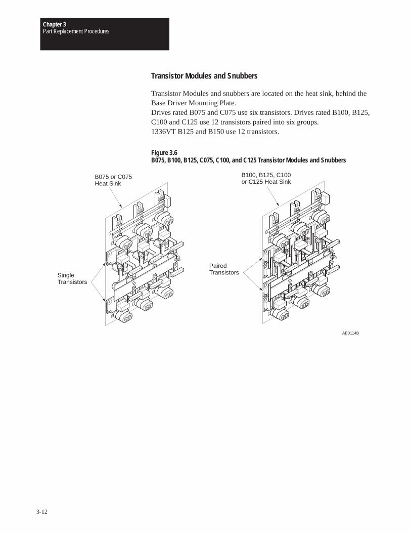
Chapter 3Part Replacement Procedures
3-12
Transistor Modules and Snubbers
Transistor Modules and snubbers are located on the heat sink, behind theBase Driver Mounting Plate.Drives rated B075 and C075 use six transistors. Drives rated B100, B125,C100 and C125 use 12 transistors paired into six groups.1336VT B125 and B150 use 12 transistors.
Figure 3.6B075, B100, B125, C075, C100, and C125 Transistor Modules and Snubbers
AB0114B
B075 or C075Heat Sink
SingleTransistors
B100, B125, C100or C125 Heat Sink
PairedTransistors
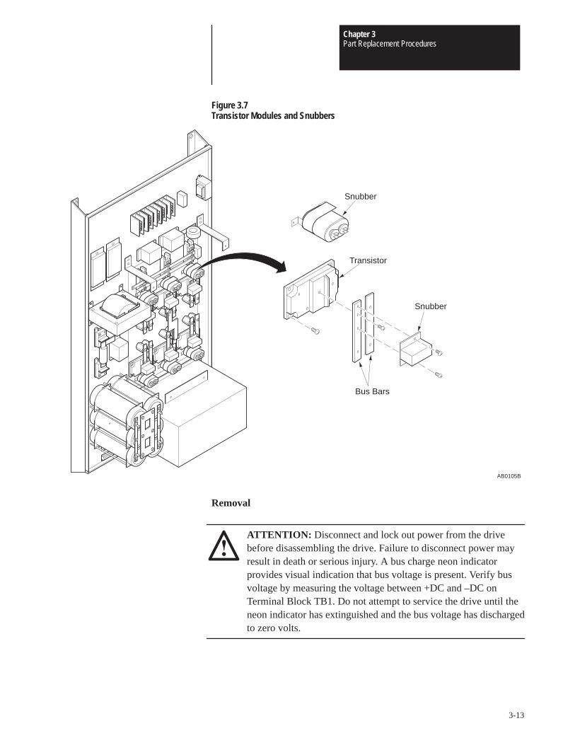
Chapter 3Part Replacement Procedures
3-13
Figure 3.7Transistor Modules and Snubbers
AB0105B
Transistor
Snubber
Snubber
Bus Bars
Removal
ATTENTION: Disconnect and lock out power from the drivebefore disassembling the drive. Failure to disconnect power mayresult in death or serious injury. A bus charge neon indicatorprovides visual indication that bus voltage is present. Verify busvoltage by measuring the voltage between +DC and –DC onTerminal Block TB1. Do not attempt to service the drive until theneon indicator has extinguished and the bus voltage has dischargedto zero volts.
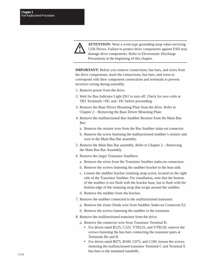
Chapter 3Part Replacement Procedures
3-14
ATTENTION: Wear a wrist-type grounding strap when servicing1336 Drives. Failure to protect drive components against ESD maydamage drive components. Refer to Electrostatic DischargePrecautions at the beginning of this chapter.
IMPORTANT: Before you remove connections, bus bars, and wires fromthe drive components, mark the connections, bus bars, and wires tocorrespond with their component connections and terminals to preventincorrect wiring during assembly.
1. Remove power from the drive.
2. Wait for Bus Indicator Light DS1 to turn off. Check for zero volts atTB1 Terminals +DC and –DC before proceeding.
3. Remove the Base Driver Mounting Plate from the drive. Refer toChapter 2 – Removing the Base Driver Mounting Plate.
4. Remove the malfunctioned Bus Snubber Resistor from the Main BusBar:
a. Remove the resistor wire from the Bus Snubber stake-on connector.
b. Remove the screw fastening the malfunctioned snubber’s resistor andwire to the Main Bus Bar assembly.
5. Remove the Main Bus Bar assembly. Refer to Chapter 2 – Removingthe Main Bus Bar Assembly.
6. Remove the larger Transistor Snubbers:
a. Remove the wires from the Transistor Snubber stake-on connectors.
b. Remove the screws fastening the snubber bracket to the heat sink.
c. Loosen the snubber bracket retaining strap screw, located on the rightside of the Transistor Snubber. For installation, note that the bottomof the snubber is not flush with the bracket base, but is flush with thebottom edge of the retaining strap that wraps around the snubber.
d. Remove the snubber from the bracket.
7. Remove the snubber connected to the malfunctioned transistor:
a. Remove the Zener Diode wire from Snubber Stake-on Connector E2.
b. Remove the screws fastening the snubber to the transistor.
8. Remove the malfunctioned transistor from the drive:
a. Remove the connector wire from Transistor Terminal B.• For drives rated B125, C125, VTB125, and VTB150, remove the
screws fastening the bus bars connecting the transistor pairs atTerminals Bx and B.
• For drives rated B075, B100, C075, and C100, loosen the screwsfastening the malfunctioned transistor Terminal C and Terminal Ebus bars to the insulated standoffs.
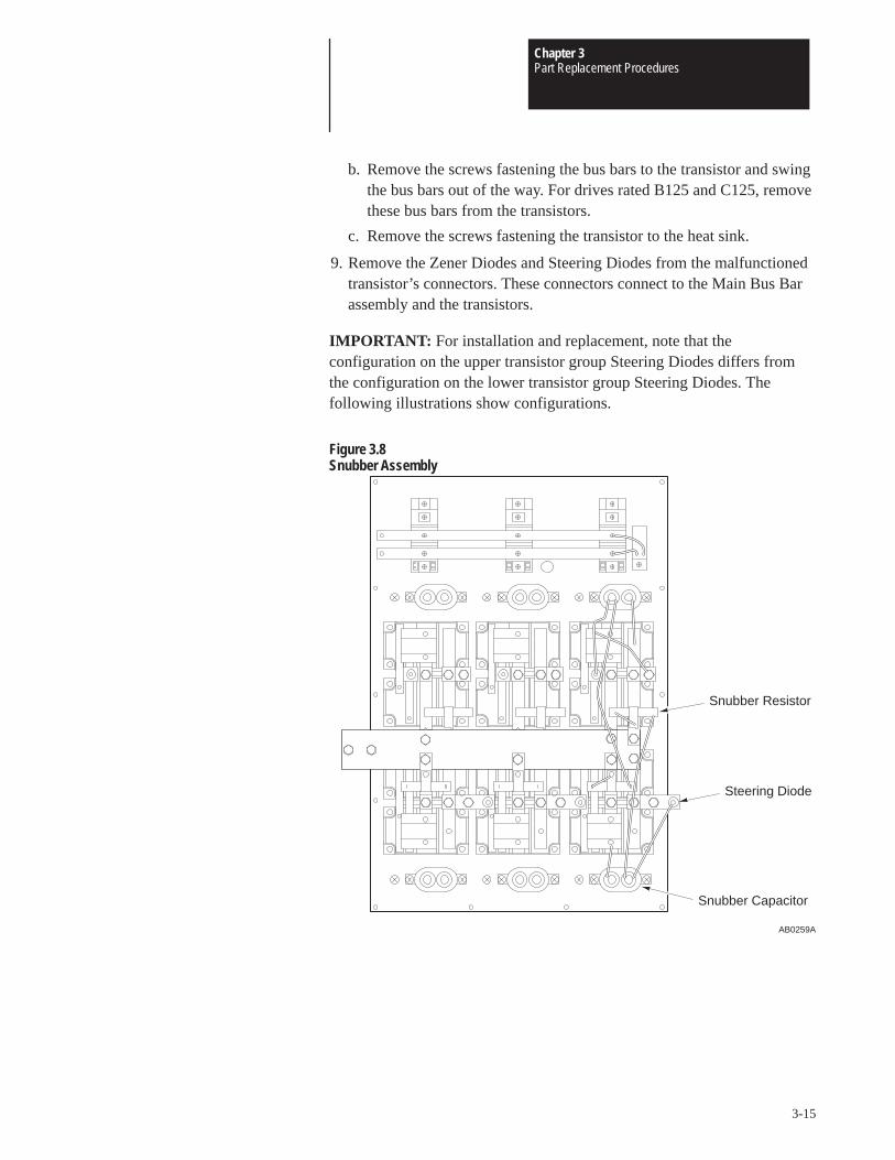
Chapter 3Part Replacement Procedures
3-15
b. Remove the screws fastening the bus bars to the transistor and swingthe bus bars out of the way. For drives rated B125 and C125, removethese bus bars from the transistors.
c. Remove the screws fastening the transistor to the heat sink.
9. Remove the Zener Diodes and Steering Diodes from the malfunctionedtransistor’s connectors. These connectors connect to the Main Bus Barassembly and the transistors.
IMPORTANT: For installation and replacement, note that theconfiguration on the upper transistor group Steering Diodes differs fromthe configuration on the lower transistor group Steering Diodes. Thefollowing illustrations show configurations.
Figure 3.8Snubber Assembly
AB0259A
Snubber Capacitor
Steering Diode
Snubber Resistor
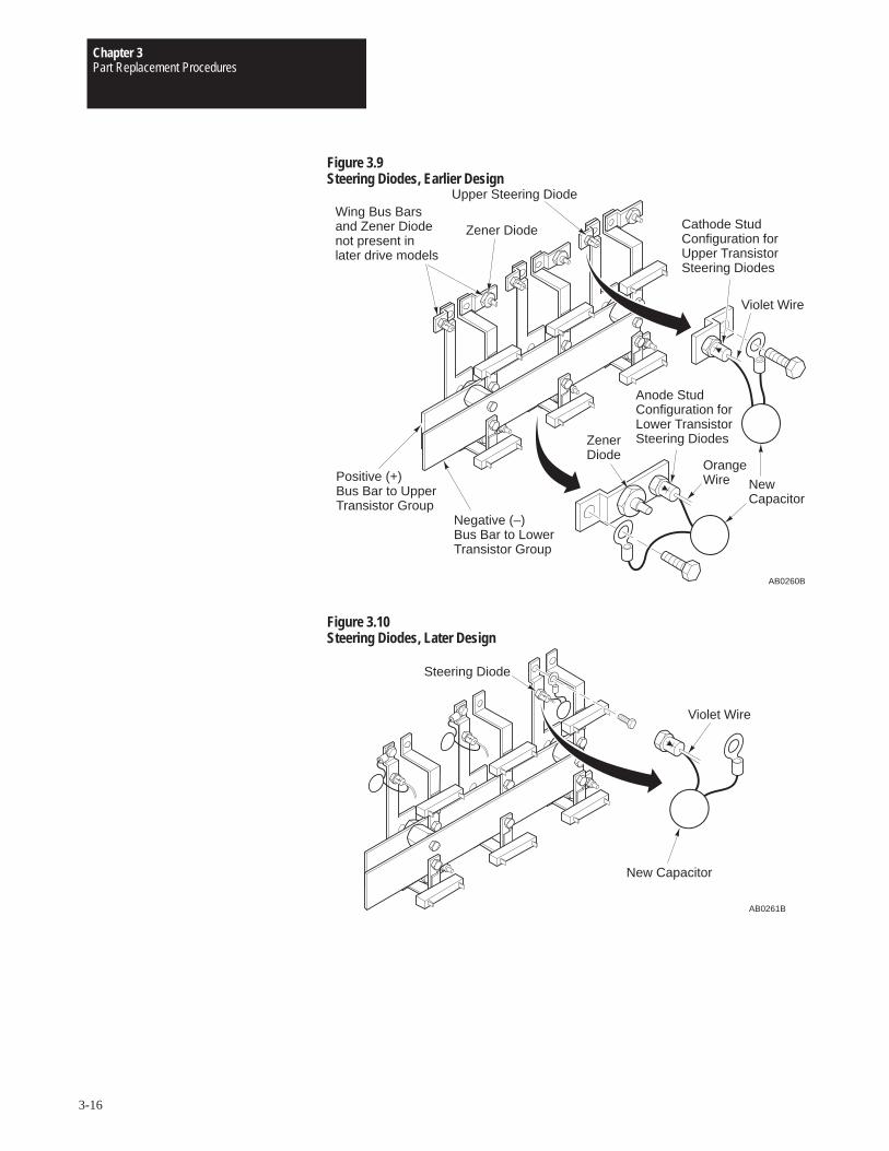
Chapter 3Part Replacement Procedures
3-16
Figure 3.9Steering Diodes, Earlier Design
AB0260B
Positive (+)Bus Bar to UpperTransistor Group
Upper Steering Diode
Negative (–)Bus Bar to LowerTransistor Group
Zener Diode
ZenerDiode
Cathode StudConfiguration forUpper TransistorSteering Diodes
Anode StudConfiguration forLower TransistorSteering Diodes
Wing Bus Barsand Zener Diodenot present inlater drive models
Violet Wire
NewCapacitor
OrangeWire
Figure 3.10Steering Diodes, Later Design
AB0261B
Steering Diode
Violet Wire
New Capacitor
Chapter 3Part Replacement Procedures
3-17
Installation
1. Clean the surfaces between the transistor and the heat sink.
2. Replace the Preform between the transistor and the heat sink.
3. Install the transistor in reverse order of removal. Always replace theTransistor Snubbers when replacing a transistor.
ATTENTION: Replace all guards before applying power to thedrive. Failure to replace guards may result in death or seriousinjury.
IMPORTANT: When you replace transistors, snubbers, and diodes,always replace the snubbers and diodes for the replaced transistor. Notethat the larger snubbers should not touch the heat sink. Mount the base ofthese snubbers flush with the bottom of the snubber bracket retaining strap.
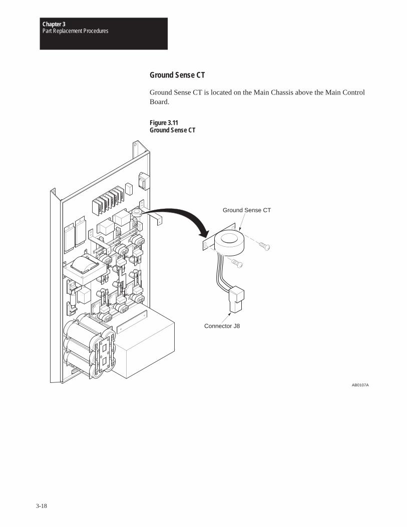
Chapter 3Part Replacement Procedures
3-18
Ground Sense CT
Ground Sense CT is located on the Main Chassis above the Main ControlBoard.
Figure 3.11Ground Sense CT
AB0107A
Connector J8
Ground Sense CT
Chapter 3Part Replacement Procedures
3-19
Removal
ATTENTION: Disconnect and lock out power from the drivebefore disassembling the drive. Failure to disconnect power mayresult in death or serious injury. A bus charge neon indicatorprovides visual indication that bus voltage is present. Verify busvoltage by measuring the voltage between +DC and –DC onTerminal Block TB1. Do not attempt to service the drive until theneon indicator has extinguished and the bus voltage has dischargedto zero volts.
ATTENTION: Wear a wrist-type grounding strap when servicing1336 Drives. Failure to protect drive components against ESD maydamage drive components. Refer to Electrostatic DischargePrecautions at the beginning of this chapter.
IMPORTANT: Before you remove connections, bus bars, and wires fromthe drive components, mark the connections, bus bars, and wires tocorrespond with their component connections and terminals to preventincorrect wiring during assembly.
1. Remove power from the drive.
2. Wait for Bus Indicator Light DS1 to turn off. Check for zero volts atTB1 Terminals +DC and –DC before proceeding.
3. Remove Ground Sense CT Connector J8 from the Base Driver Board.
4. Remove the wires from the TB1 Terminal L1, L2, and L3 connections.
5. Remove the two screws fastening Ground Sense CT to the MainChassis.
6. Slide Ground Sense CT off the TB1 Terminal L1, L2, and L3 wires.
Installation
Install Ground Sense CT in reverse order of removal.
IMPORTANT: Pass the TB1 Terminal L1, L2, and L3 wires throughGround Sense CT before connecting the wires to the bridge rectifiers.
ATTENTION: Replace all guards before applying power to thedrive. Failure to replace guards may result in death or seriousinjury.
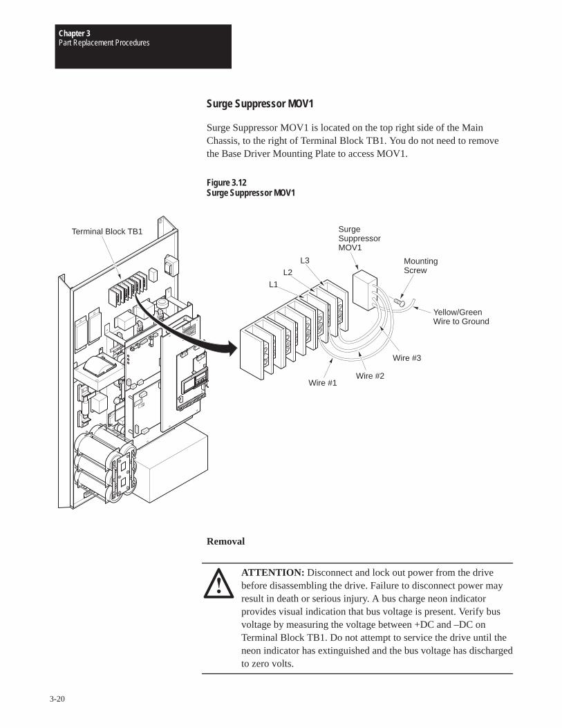
Chapter 3Part Replacement Procedures
3-20
Surge Suppressor MOV1
Surge Suppressor MOV1 is located on the top right side of the MainChassis, to the right of Terminal Block TB1. You do not need to removethe Base Driver Mounting Plate to access MOV1.
Figure 3.12Surge Suppressor MOV1
Yellow/Green Wire to Ground
Surge SuppressorMOV1
L3
L2L1
Terminal Block TB1
Wire #1Wire #2
Wire #3
MountingScrew
Removal
ATTENTION: Disconnect and lock out power from the drivebefore disassembling the drive. Failure to disconnect power mayresult in death or serious injury. A bus charge neon indicatorprovides visual indication that bus voltage is present. Verify busvoltage by measuring the voltage between +DC and –DC onTerminal Block TB1. Do not attempt to service the drive until theneon indicator has extinguished and the bus voltage has dischargedto zero volts.
Chapter 3Part Replacement Procedures
3-21
ATTENTION: Wear a wrist-type grounding strap when servicing1336 Drives. Failure to protect drive components against ESD maydamage drive components. Refer to Electrostatic DischargePrecautions at the beginning of this chapter.
IMPORTANT: Before you remove connections, bus bars, and wires fromthe drive components, mark the connections, bus bars, and wires tocorrespond with their component connections and terminals to preventincorrect wiring during assembly.
1. Remove power from the drive.
2. Wait for Bus Indicator Light DS1 to turn off. Check for zero volts atTB1 Terminals +DC and –DC before proceeding.
3. Remove MOV1 wires from the following:
• Yellow/green wire from the ground location on the top right corner ofthe Main Chassis.
• Wire #1 from TB1, Terminal L1
• Wire #2 from TB1, Terminal L2
• Wire #3 from TB1, Terminal L3
4. Remove the screw fastening MOV1 to the drive.
Installation
Install Surge Suppressor MOV1 in reverse order of removal. Note that theneutral-ground wire on the new MOV1 is yellow on green.
ATTENTION: Replace all guards before applying power to thedrive. Failure to replace guards may result in death or seriousinjury.
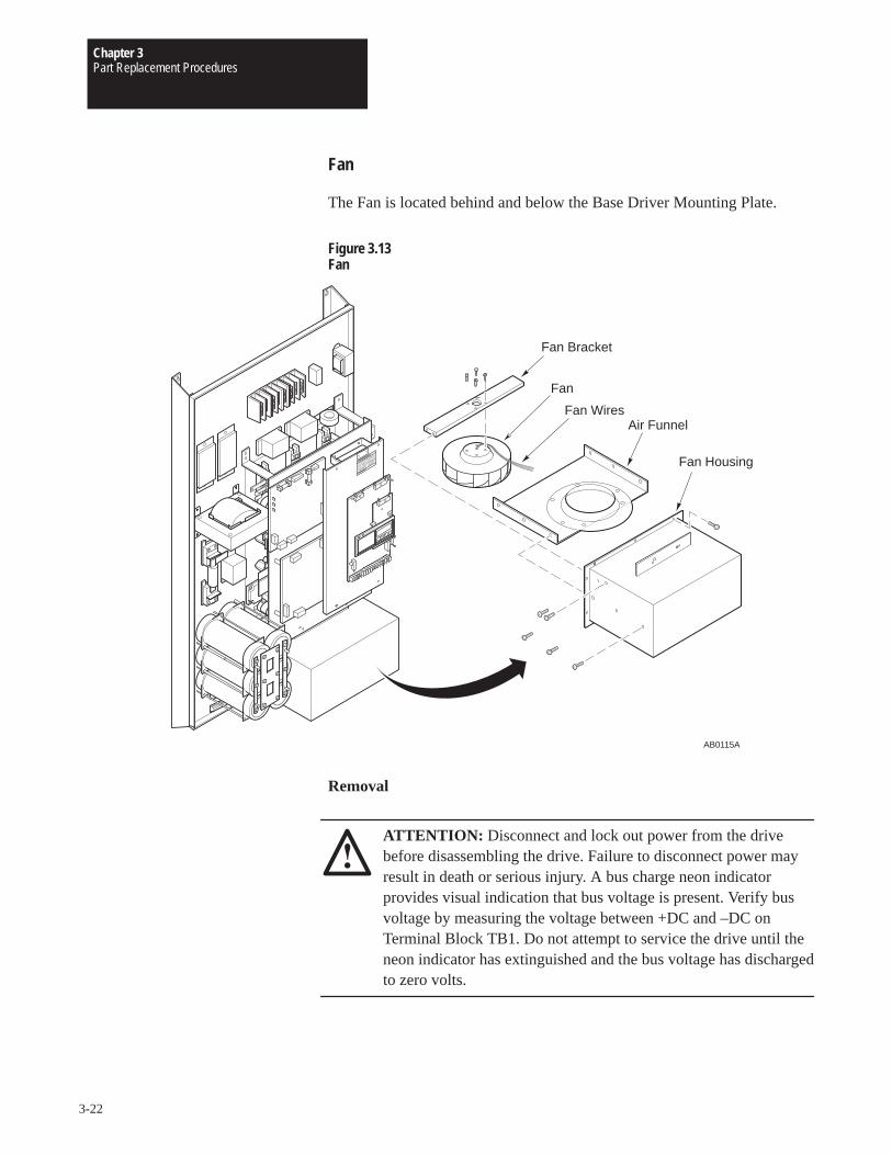
Chapter 3Part Replacement Procedures
3-22
Fan
The Fan is located behind and below the Base Driver Mounting Plate.
Figure 3.13Fan
AB0115A
Fan Bracket
Fan
Fan WiresAir Funnel
Fan Housing
Removal
ATTENTION: Disconnect and lock out power from the drivebefore disassembling the drive. Failure to disconnect power mayresult in death or serious injury. A bus charge neon indicatorprovides visual indication that bus voltage is present. Verify busvoltage by measuring the voltage between +DC and –DC onTerminal Block TB1. Do not attempt to service the drive until theneon indicator has extinguished and the bus voltage has dischargedto zero volts.
Chapter 3Part Replacement Procedures
3-23
ATTENTION: Wear a wrist-type grounding strap when servicing1336 Drives. Failure to protect drive components against ESD maydamage drive components. Refer to Electrostatic DischargePrecautions at the beginning of this chapter.
IMPORTANT: Before you remove connections, bus bars, and wires fromthe drive components, mark the connections, bus bars, and wires tocorrespond with their component connections and terminals to preventincorrect wiring during assembly.
1. Remove power from the drive.
2. Wait for Bus Indicator Light DS1 to turn off. Check for zero volts atTB1 Terminals +DC and –DC before proceeding.
3. Remove the Base Driver Mounting Plate from the drive. Refer toChapter 2 – Removing the Base Driver Mounting Plate.
4. Remove the 0V and 115V wires from the terminal block located on theright side of the Fan Housing.
5. Remove the screws fastening the Fan Housing to the chassis.
6. Pull the Fan Housing away from the drive.
7. Place the Fan Housing on a surface with the open side of the housingfacing up.
8. Cut all fan wires at the adjustable grommet, located on the side of theFan Housing.
9. Remove the screws fastening the Air Funnel to the inside of the FanHousing.
10. Remove the four screws fastening the horizontal Fan Bracket to theinside of the Fan Housing. Two screws are located near the top edge ofeach side of the Fan Housing.
11. Loosen the nut on the adjustable grommet and remove the wires fromthe grommet.
12. Remove the Fan from the Fan Housing.
13. Remove the wires from the Fan Capacitor stake-on connectors.
14. Remove the screws fastening the Fan Capacitor to the Fan Housing.
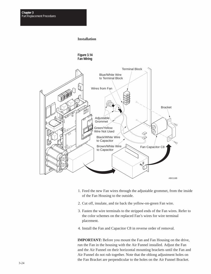
Chapter 3Part Replacement Procedures
3-24
Installation
Figure 3.14Fan Wiring
Bracket
AB0116B
Terminal Block
Fan Capacitor C8
Green/YellowWire Not Used
Blue/White Wireto Terminal Block
Wires from Fan
Black/White Wireto Capacitor
AdjustableGrommet
Brown/White Wireto Capacitor
1. Feed the new Fan wires through the adjustable grommet, from the insideof the Fan Housing to the outside.
2. Cut off, insulate, and tie back the yellow-on-green Fan wire.
3. Fasten the wire terminals to the stripped ends of the Fan wires. Refer tothe color schemes on the replaced Fan’s wires for wire terminalplacement.
4. Install the Fan and Capacitor C8 in reverse order of removal.
IMPORTANT: Before you mount the Fan and Fan Housing on the drive,run the Fan in the housing with the Air Funnel installed. Adjust the Fanand the Air Funnel on their horizontal mounting brackets until the Fan andAir Funnel do not rub together. Note that the oblong adjustment holes onthe Fan Bracket are perpendicular to the holes on the Air Funnel Bracket.
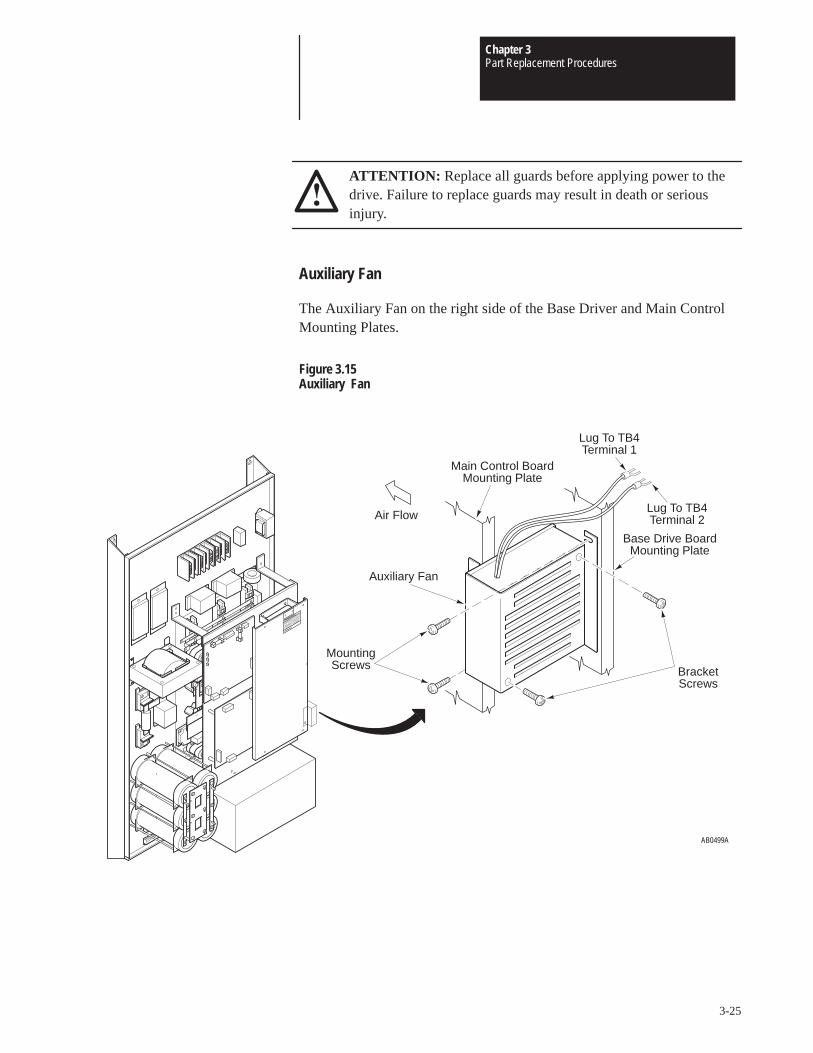
Chapter 3Part Replacement Procedures
3-25
ATTENTION: Replace all guards before applying power to thedrive. Failure to replace guards may result in death or seriousinjury.
Auxiliary Fan
The Auxiliary Fan on the right side of the Base Driver and Main ControlMounting Plates.
Figure 3.15Auxiliary Fan
AB0499A
Air Flow
Main Control BoardMounting Plate
Lug To TB4Terminal 1
Lug To TB4Terminal 2
Base Drive BoardMounting Plate
Auxiliary Fan
MountingScrews Bracket
Screws
Chapter 3Part Replacement Procedures
3-26
Removal
!ATTENTION: Some printed circuit boards and drive componentsmay contain hazardous voltage levels. If Bus Indicator neon lightDS1 on the Base Driver Board is illuminated, hazardous voltagesare present in the drive circuit boards. Remove power before youdisconnect or reconnect wires, and before you remove or replacefuses and circuit boards. Verify bus voltage by measuring thevoltage between +DC and –DC on Terminal Block TB1. Do notattempt to service the drive until the neon indicator hasextinguished and the bus voltage has discharged to zero volts.
!ATTENTION: This assembly contains parts and sub-assembliesthat are sensitive to electrostatic discharge. Static controlprecautions are required when servicing this assembly. Componentdamage may result if you ignore electrostatic discharge controlprocedures. If you are not familiar with static control procedures,reference Allen-Bradley Publication 8000–4.5.2, Guarding AgainstElectrostatic Discharge, or any other applicable ESD protectionhandbook.
IMPORTANT: Before you remove connections, bus bars, and wires fromthe drive components, mark the connections, bus bars, and wires tocorrespond with their component connections and terminals to preventincorrect wiring during assembly.
1. Remove power from the drive.
2. Wait for Bus Indicator Light DS1 to turn off. Check for zero volts atTB1 Terminals +DC and –DC before proceeding.
3. Loosen the screws fastening the fan wires to terminals 1 and 2 onTerminal Block TB4, located on the right side of the Main Fan housing.
4. Remove the fan wires from TB4 and from the nylon fasteners.
5. Loosen the two screws fastening the Auxiliary Fan bracket to theControl Main Mounting Plate and the Base Driver Mounting Plate.
6. Slide the fan to the right to remove the fan from the drive.
7. Remove the two screws fastening the fan to the bracket to remove thefan from the bracket.
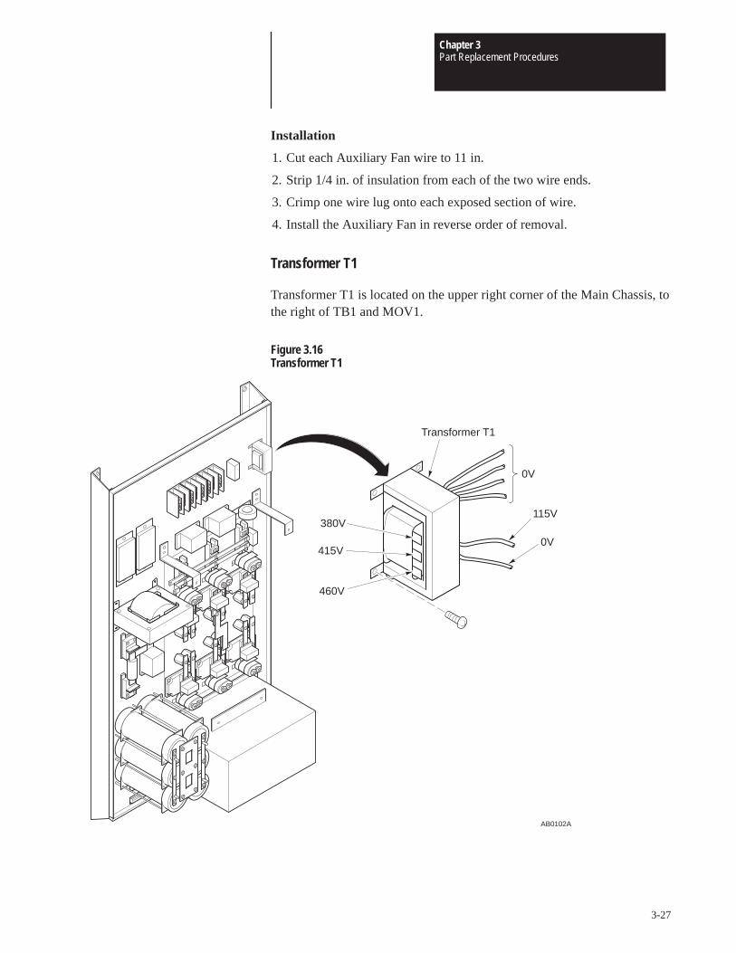
Chapter 3Part Replacement Procedures
3-27
Installation
1. Cut each Auxiliary Fan wire to 11 in.
2. Strip 1/4 in. of insulation from each of the two wire ends.
3. Crimp one wire lug onto each exposed section of wire.
4. Install the Auxiliary Fan in reverse order of removal.
Transformer T1
Transformer T1 is located on the upper right corner of the Main Chassis, tothe right of TB1 and MOV1.
Figure 3.16Transformer T1
115V
0V
AB0102A
Transformer T1
0V
380V
415V
460V
Chapter 3Part Replacement Procedures
3-28
Removal
ATTENTION: Disconnect and lock out power from the drivebefore disassembling the drive. Failure to disconnect power mayresult in death or serious injury. A bus charge neon indicatorprovides visual indication that bus voltage is present. Verify busvoltage by measuring the voltage between +DC and –DC onTerminal Block TB1. Do not attempt to service the drive until theneon indicator has extinguished and the bus voltage has dischargedto zero volts.
ATTENTION: Wear a wrist-type grounding strap when servicing1336 Drives. Failure to protect drive components against ESD maydamage drive components. Refer to Electrostatic DischargePrecautions at the beginning of this chapter.
IMPORTANT: Before you remove connections, bus bars, and wires fromthe drive components, mark the connections, bus bars, and wires tocorrespond with their component connections and terminals to preventincorrect wiring during assembly.
1. Remove power from the drive.
2. Wait for Bus Indicator Light DS1 to turn off. Check for zero volts atTB1 Terminals +DC and –DC before proceeding.
3. Remove the transformer 0V and 115V wires from the terminal block onthe right side of the Fan Housing. The Fan Housing is located at thebottom of the drive.
4. Remove the wire from Transformer T1 380V, 415V, or 460V stake-onconnector.
5. Remove the screws fastening T1 to the Main Chassis.
6. Remove the mounting brackets from T1.
Installation
Install Transformer T1 in reverse order of removal. Insulate and tie backany unused T1 voltage taps.
ATTENTION: Replace all guards before applying power to thedrive. Failure to replace guards may result in death or seriousinjury.
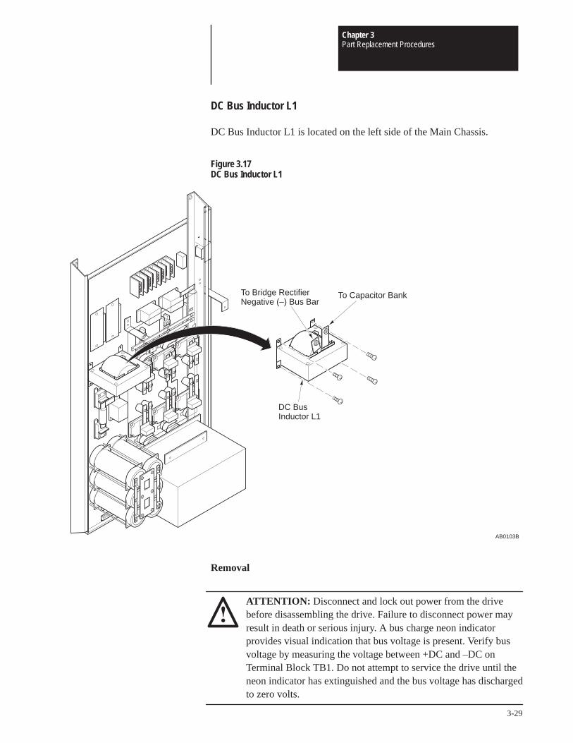
Chapter 3Part Replacement Procedures
3-29
DC Bus Inductor L1
DC Bus Inductor L1 is located on the left side of the Main Chassis.
Figure 3.17DC Bus Inductor L1
AB0103B
To Bridge RectifierNegative (–) Bus Bar
To Capacitor Bank
DC Bus Inductor L1
Removal
ATTENTION: Disconnect and lock out power from the drivebefore disassembling the drive. Failure to disconnect power mayresult in death or serious injury. A bus charge neon indicatorprovides visual indication that bus voltage is present. Verify busvoltage by measuring the voltage between +DC and –DC onTerminal Block TB1. Do not attempt to service the drive until theneon indicator has extinguished and the bus voltage has dischargedto zero volts.
Chapter 3Part Replacement Procedures
3-30
ATTENTION: Wear a wrist-type grounding strap when servicing1336 Drives. Failure to protect drive components against ESD maydamage drive components. Refer to Electrostatic DischargePrecautions at the beginning of this chapter.
IMPORTANT: Before you remove connections, bus bars, and wires fromthe drive components, mark the connections, bus bars, and wires tocorrespond with their component connections and terminals to preventincorrect wiring during assembly.
1. Remove power from the drive.
2. Wait for Bus Indicator Light DS1 to turn off. Check for zero volts atTB1 Terminals +DC and –DC before proceeding.
3. Remove the screws fastening the wires to the inductor.
4. Remove the screws fastening the inductor to the Main Chassis.
5. Remove the brackets from the inductor.
Installation
Install DC Bus Inductor L1 in reverse order of removal.
ATTENTION: Replace all guards before applying power to thedrive. Failure to replace guards may result in death or seriousinjury.
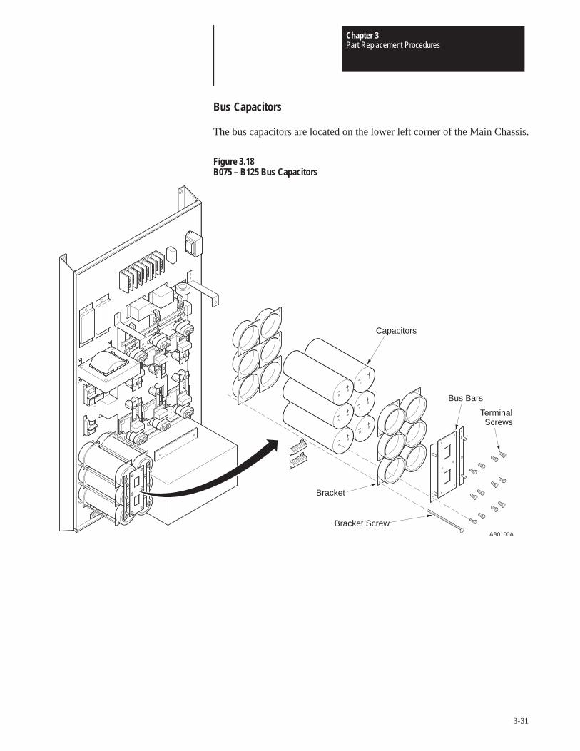
Chapter 3Part Replacement Procedures
3-31
Bus Capacitors
The bus capacitors are located on the lower left corner of the Main Chassis.
Figure 3.18B075 – B125 Bus Capacitors
Capacitors
Bracket
Bracket Screw
TerminalScrews
Bus Bars
AB0100A
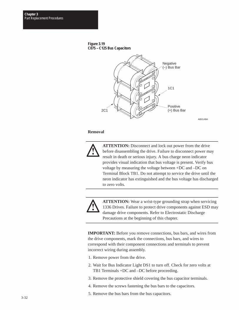
Chapter 3Part Replacement Procedures
3-32
Figure 3.19C075 – C125 Bus Capacitors
Negative(–) Bus Bar
2C1
1C1
Positive(+) Bus Bar
AB0149A
Removal
ATTENTION: Disconnect and lock out power from the drivebefore disassembling the drive. Failure to disconnect power mayresult in death or serious injury. A bus charge neon indicatorprovides visual indication that bus voltage is present. Verify busvoltage by measuring the voltage between +DC and –DC onTerminal Block TB1. Do not attempt to service the drive until theneon indicator has extinguished and the bus voltage has dischargedto zero volts.
ATTENTION: Wear a wrist-type grounding strap when servicing1336 Drives. Failure to protect drive components against ESD maydamage drive components. Refer to Electrostatic DischargePrecautions at the beginning of this chapter.
IMPORTANT: Before you remove connections, bus bars, and wires fromthe drive components, mark the connections, bus bars, and wires tocorrespond with their component connections and terminals to preventincorrect wiring during assembly.
1. Remove power from the drive.
2. Wait for Bus Indicator Light DS1 to turn off. Check for zero volts atTB1 Terminals +DC and –DC before proceeding.
3. Remove the protective shield covering the bus capacitor terminals.
4. Remove the screws fastening the bus bars to the capacitors.
5. Remove the bus bars from the bus capacitors.
Chapter 3Part Replacement Procedures
3-33
6. Remove the bracket screws fastening the malfunctioned capacitor to theMain Chassis.
7. Remove the screws fastening the malfunctioned Balancing Resistor tothe Main Chassis.
Installation
1. Loosely fasten the capacitors to the Main Chassis using the brackets andscrews.
2. Loosely fasten all bus bars and wires to the capacitors.
ATTENTION: Any capacitors not connected correctly willexplode and may cause death or serious injury.On B075 – B125 drives, the bus bar on the far left of the CapacitorGroup must connect three negative (–) capacitor terminals. The busbar on the far right of the Capacitor Group must connect threepositive (+) capacitor terminals. The bus bar in the middle will thenconnect properly to the capacitor terminals.Refer to the former illustration for C075 – C125 capacitor and busbar configuration.
3. Tighten the capacitor bracket screws.
4. Tighten the screws fastening the bus bars to the capacitors.
5. Tighten the wires to the bus bars.
6. Fasten the protective shield to cover the capacitor terminals.
ATTENTION: Replace all guards before applying power to thedrive. Failure to replace guards may result in death or seriousinjury.
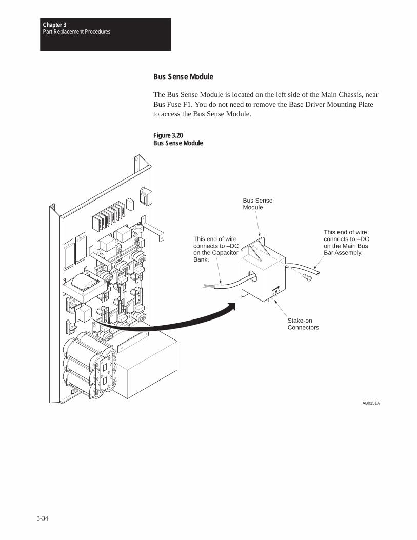
Chapter 3Part Replacement Procedures
3-34
Bus Sense Module
The Bus Sense Module is located on the left side of the Main Chassis, nearBus Fuse F1. You do not need to remove the Base Driver Mounting Plateto access the Bus Sense Module.
Figure 3.20Bus Sense Module
AB0151A
This end of wireconnects to –DCon the CapacitorBank.
This end of wireconnects to –DCon the Main BusBar Assembly.
Bus SenseModule
Stake-onConnectors
Chapter 3Part Replacement Procedures
3-35
Removal
ATTENTION: Disconnect and lock out power from the drivebefore disassembling the drive. Failure to disconnect power mayresult in death or serious injury. A bus charge neon indicatorprovides visual indication that bus voltage is present. Verify busvoltage by measuring the voltage between +DC and –DC onTerminal Block TB1. Do not attempt to service the drive until theneon indicator has extinguished and the bus voltage has dischargedto zero volts.
ATTENTION: Wear a wrist-type grounding strap when servicing1336 Drives. Failure to protect drive components against ESD maydamage drive components. Refer to Electrostatic DischargePrecautions at the beginning of this chapter.
IMPORTANT: Before you remove connections, bus bars, and wires fromthe drive components, mark the connections, bus bars, and wires tocorrespond with their component connections and terminals to preventincorrect wiring during assembly.
1. Remove power from the drive.
2. Wait for Bus Indicator Light DS1 to turn off. Check for zero volts atTB1 Terminals +DC and –DC before proceeding. These terminals arelocated in the upper left corner of the drive.
3. Remove the screws fastening the –DC wire to the Main Bus Barassembly.
4. Pull the –DC wire through the hole in the Bus Sense Module.
5. Remove the wires from the Bus Sense Module stake-on connectors.
6. Remove the screws fastening the Bus Sense Module to the MainChassis.
Installation
Install the Bus Sense Module in reverse order of removal.
IMPORTANT: Pass the –DC wire through the hole in the Bus SenseModule before you fasten the wire to the negative bus bar on the Main BusBar assembly. The arrow on the Bus Sense Module indicates the directionthe –DC wire must travel as the wire passes through the Bus Sense Moduleand connects to the negative bus bar.
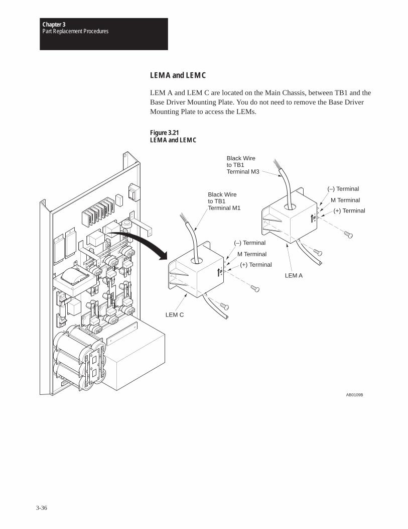
Chapter 3Part Replacement Procedures
3-36
LEM A and LEM C
LEM A and LEM C are located on the Main Chassis, between TB1 and theBase Driver Mounting Plate. You do not need to remove the Base DriverMounting Plate to access the LEMs.
Figure 3.21LEM A and LEM C
AB0109B
Black Wire to TB1Terminal M1
(–) Terminal
M Terminal
(+) Terminal
LEM C
(–) Terminal
M Terminal
(+) Terminal
LEM A
Black Wire to TB1Terminal M3
Chapter 3Part Replacement Procedures
3-37
Removal
ATTENTION: Disconnect and lock out power from the drivebefore disassembling the drive. Failure to disconnect power mayresult in death or serious injury. A bus charge neon indicatorprovides visual indication that bus voltage is present. Verify busvoltage by measuring the voltage between +DC and –DC onTerminal Block TB1. Do not attempt to service the drive until theneon indicator has extinguished and the bus voltage has dischargedto zero volts.
ATTENTION: Wear a wrist-type grounding strap when servicing1336 Drives. Failure to protect drive components against ESD maydamage drive components. Refer to Electrostatic DischargePrecautions at the beginning of this chapter.
IMPORTANT: Before you remove connections, bus bars, and wires fromthe drive components, mark the connections, bus bars, and wires tocorrespond with their component connections and terminals to preventincorrect wiring during assembly.
1. Remove power from the drive.
2. Wait for Bus Indicator Light DS1 to turn off. Check for zero volts atTB1 Terminals +DC and –DC before proceeding.
3. Remove the wire from TB1 Terminal:
• M3 if you are replacing LEM A
• M1 if you are replacing LEM C
4. Remove the wires from the malfunctioned LEM stake-on connectors.
5. Remove the screws fastening the malfunctioned LEM to the MainChassis.
6. Slide the malfunctioned LEM off of the M1 or M3 wire.
Installation
Install LEM A and LEM C in reverse order of removal.
ATTENTION: Replace all guards before applying power to thedrive. Failure to replace guards may result in death or seriousinjury.
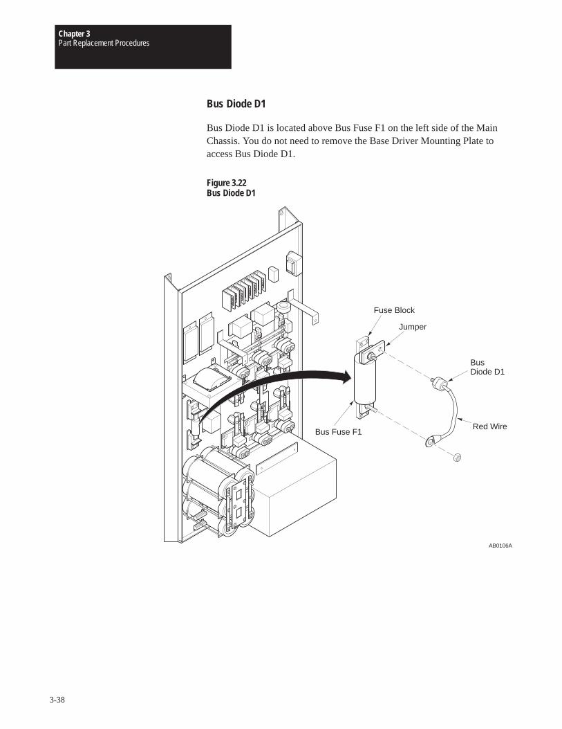
Chapter 3Part Replacement Procedures
3-38
Bus Diode D1
Bus Diode D1 is located above Bus Fuse F1 on the left side of the MainChassis. You do not need to remove the Base Driver Mounting Plate toaccess Bus Diode D1.
Figure 3.22Bus Diode D1
AB0106A
Red Wire
Bus Diode D1
Jumper
Bus Fuse F1
Fuse Block
Chapter 3Part Replacement Procedures
3-39
Removal
ATTENTION: Disconnect and lock out power from the drivebefore disassembling the drive. Failure to disconnect power mayresult in death or serious injury. A bus charge neon indicatorprovides visual indication that bus voltage is present. Verify busvoltage by measuring the voltage between +DC and –DC onTerminal Block TB1. Do not attempt to service the drive until theneon indicator has extinguished and the bus voltage has dischargedto zero volts.
ATTENTION: Wear a wrist-type grounding strap when servicing1336 Drives. Failure to protect drive components against ESD maydamage drive components. Refer to Electrostatic DischargePrecautions at the beginning of this chapter.
IMPORTANT: Before you remove connections, bus bars, and wires fromthe drive components, mark the connections, bus bars, and wires tocorrespond with their component connections and terminals to preventincorrect wiring during assembly.
1. Remove power from the drive.
2. Wait for Bus Indicator Light DS1 to turn off. Check for zero volts atTB1 Terminals +DC and –DC before proceeding.
3. Remove the nut fastening the bus diode wire to the fuse block.
4. Remove Bus Diode D1 from the fuse jumper.
InstallationInstall Bus Diode D1 in reverse order of removal.
ATTENTION: Replace all guards before applying power to thedrive. Failure to replace guards may result in death or seriousinjury.
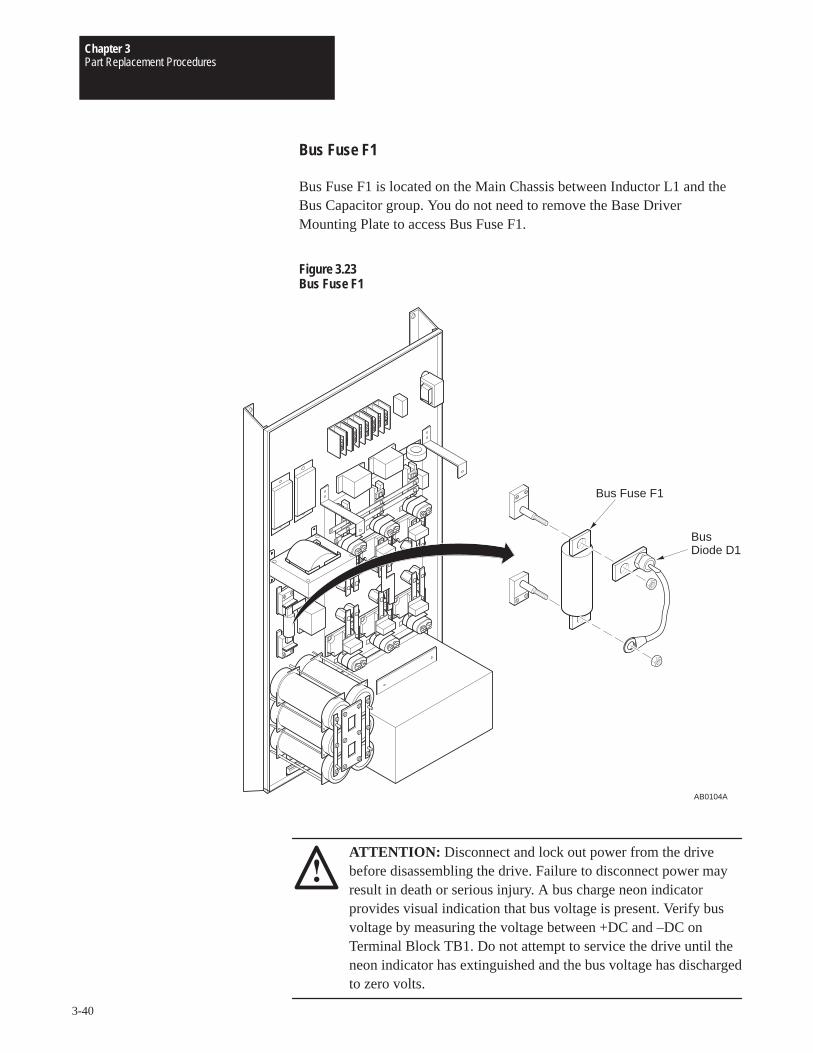
Chapter 3Part Replacement Procedures
3-40
Bus Fuse F1
Bus Fuse F1 is located on the Main Chassis between Inductor L1 and theBus Capacitor group. You do not need to remove the Base DriverMounting Plate to access Bus Fuse F1.
Figure 3.23Bus Fuse F1
AB0104A
Bus Diode D1
Bus Fuse F1
ATTENTION: Disconnect and lock out power from the drivebefore disassembling the drive. Failure to disconnect power mayresult in death or serious injury. A bus charge neon indicatorprovides visual indication that bus voltage is present. Verify busvoltage by measuring the voltage between +DC and –DC onTerminal Block TB1. Do not attempt to service the drive until theneon indicator has extinguished and the bus voltage has dischargedto zero volts.
Chapter 3Part Replacement Procedures
3-41
ATTENTION: Wear a wrist-type grounding strap when servicing1336 Drives. Failure to protect drive components against ESD maydamage drive components. Refer to Electrostatic DischargePrecautions at the beginning of this chapter.
IMPORTANT: Before you remove connections, bus bars, and wires fromthe drive components, mark the connections, bus bars, and wires tocorrespond with their component connections and terminals to preventincorrect wiring during assembly.
1. Remove power from the drive.
2. Wait for Bus Indicator Light DS1 to turn off. Check for zero volts atTB1 Terminals +DC and –DC before proceeding.
3. Remove the screws fastening the bus fuse to the fuse block.
4. Remove the bus fuse from the fuse block.
InstallationInstall Bus Fuse F1 in reverse order of removal.
ATTENTION: Replace all guards before applying power to thedrive. Failure to replace guards may result in death or seriousinjury.

Chapter 3Part Replacement Procedures
3-42
This Page Intentionally Left Blank
Chapter
4-1
Replacement Parts List
Chapter Objectives This chapter illustrates and lists replacement parts for the 1336 Drivesrated B075 – B125, C075 – C125, and 1336VT B075 – B150, anddescribes replacement parts ordering procedures.
Ordering Replacement Parts For your convenience, the Allen-Bradley Motion Control Division and theAllen-Bradley Support Division provide efficient and convenient repairand exchange for eligible equipment.
A product service report number is required to return any equipment forrepair. Your local Allen-Bradley distributor or area sales and support officecan provide you with a product service report number.
You should return equipment to be repaired to the area sales and supportcenter nearest you. Reference the product service report number on thecarton and packing slip. Include:
• Your company name
• Your company address
• The repair purchase order number
• A brief description of the problem
Contact your local Allen-Bradley distributor or sales office for a completelisting of area sales and support centers near you.
Part numbers refer to publication 1336-6.0.
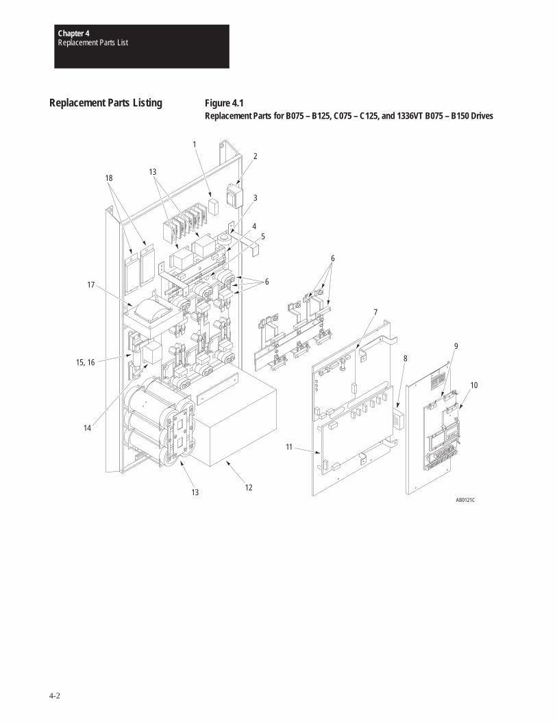
Chapter 4Replacement Parts List
4-2
Replacement Parts Listing Figure 4.1Replacement Parts for B075 – B125, C075 – C125, and 1336VT B075 – B150 Drives
AB0121C
11
6
1
9
10
7
4
3
2
12
14
15, 16
17
1813
13
5
6
8
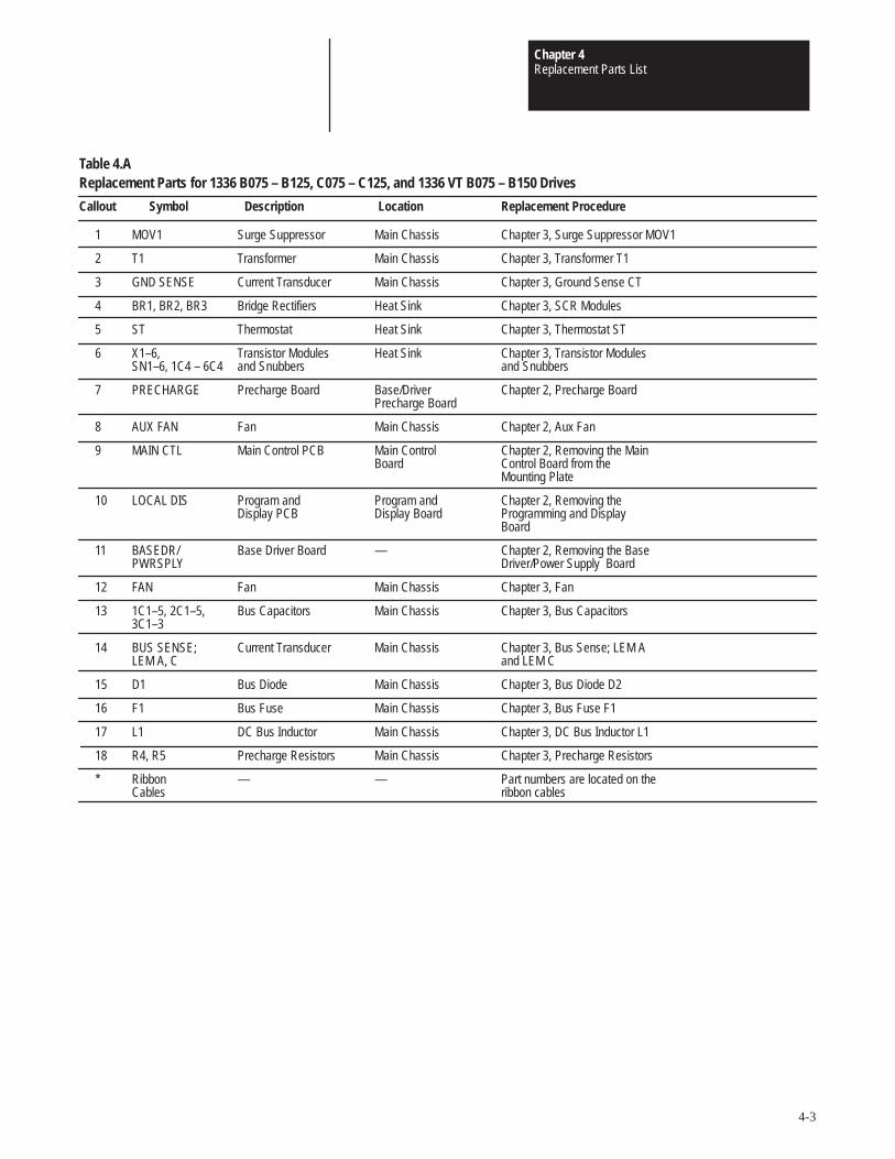
Chapter 4Replacement Parts List
4-3
Table 4.AReplacement Parts for 1336 B075 – B125, C075 – C125, and 1336 VT B075 – B150 Drives
Callout Symbol Description Location Replacement Procedure
1 MOV1 Surge Suppressor Main Chassis Chapter 3, Surge Suppressor MOV1
2 T1 Transformer Main Chassis Chapter 3, Transformer T1
3 GND SENSE Current Transducer Main Chassis Chapter 3, Ground Sense CT
4 BR1, BR2, BR3 Bridge Rectifiers Heat Sink Chapter 3, SCR Modules
5 ST Thermostat Heat Sink Chapter 3, Thermostat ST
6 X1–6, Transistor Modules Heat Sink Chapter 3, Transistor ModulesSN1–6, 1C4 – 6C4 and Snubbers and Snubbers
7 PRECHARGE Precharge Board Base/Driver Chapter 2, Precharge BoardPrecharge Board
8 AUX FAN Fan Main Chassis Chapter 2, Aux Fan
9 MAIN CTL Main Control PCB Main Control Chapter 2, Removing the MainBoard Control Board from the
Mounting Plate
10 LOCAL DIS Program and Program and Chapter 2, Removing theDisplay PCB Display Board Programming and Display
Board
11 BASEDR/ Base Driver Board — Chapter 2, Removing the BasePWRSPLY Driver/Power Supply Board
12 FAN Fan Main Chassis Chapter 3, Fan
13 1C1–5, 2C1–5, Bus Capacitors Main Chassis Chapter 3, Bus Capacitors3C1–3
14 BUS SENSE; Current Transducer Main Chassis Chapter 3, Bus Sense; LEM A LEM A, C and LEM C
15 D1 Bus Diode Main Chassis Chapter 3, Bus Diode D2
16 F1 Bus Fuse Main Chassis Chapter 3, Bus Fuse F1
17 L1 DC Bus Inductor Main Chassis Chapter 3, DC Bus Inductor L1
18 R4, R5 Precharge Resistors Main Chassis Chapter 3, Precharge Resistors
* Ribbon — — Part numbers are located on theCables ribbon cables

Chapter 4Replacement Parts List
4-4
This Page Intentionally Left Blank

B075 – B125, C075 – C1251336 Schematics
S-1
75 – 125 HP 1336 Drives
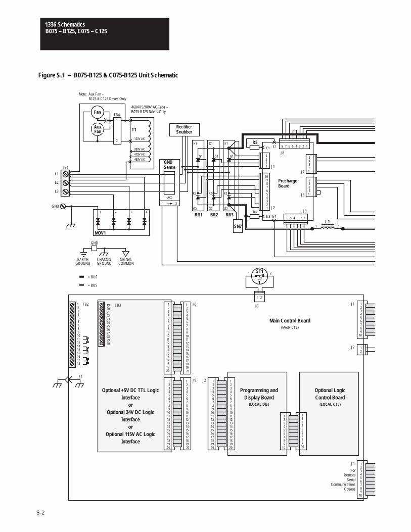
B075 – B125, C075 – C1251336 Schematics
S-2
1234567891011121314151617181920
123456789
1011121314151617181920
1234567891011121314151617181920
123456789
1011121314151617181920
1234567891011121314151617181920
123456789
1011121314151617181920
TB3
123456
1234
4321
TB1
L1
L2
L3
GNDG2
G1
MOV1
(AC)
1 2ST1
1 2
123456789101112131415161718
TB2
E1
192021222324252627282930
J9 J2
J8
12345678910
123456789
10
123456789
10
123456789
10
GND
EARTHGROUND
CHASSISGROUND
SIGNALCOMMON
+ BUS
– BUS
J6 J1
J7
J4
Fan
T1
415V AC
380V AC
460V AC
BR1 BR2 BR3
21
120V AC
1
2
TB4
123456789
10
12345
K2
G2
G1
K2
G2
G1
K2
SN7
R4
E3
R5E1
E4
E2 12345678
12345
J5
J6
J7
J8
J1
J2
L11 2
Figure S.1 – B075-B125 & C075-B125 Unit Schematic
12
K1K1K1
PrechargeBoard
RectifierSnubber
GNDSense
Main Control Board(MAIN CTL)
Optional +5V DC TTL LogicInterface
orOptional 24V DC Logic
Interfaceor
Optional 115V AC LogicInterface
Programming andDisplay Board
(LOCAL DIS)
Optional LogicControl Board
(LOCAL CTL)
ForRemote
SerialCommunications
Options
460/415/380V AC Taps –B075-B125 Drives Only
AuxFan
Note: Aux Fan –B125 & C125 Drives Only
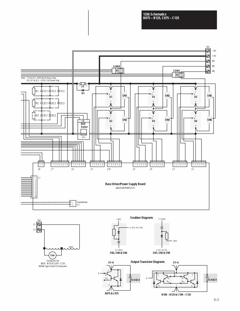
B075 – B125, C075 – C1251336 Schematics
S-3
12345678910
J1
21 1 2 3 4 5 6 7 8
J8 J7
TB1
– DC
+ DC
M1
M2
M3
1 2 3 4 5 6
J6
1 2 3 4 5 6
J5
1 2 3 4 5 6
J10
1 2 3 4 5 6
J4
1 2 3 4 5 6
J9
1 2 3 4 5 6
J3
1 2 3 4 5 6
J2
BSN5X5
C
E
B SN6X6
C
E
+–
LEM C
BSN3X3
C
E
B SN4X4
C
E
BSN1X1
C
E
B SN2X2
C
E
+–
LEM A
D1
F11 2
X1–6
C
BB
B X
E
C
B
B X
C
B
B X
X1–6
B
E E
C
E
12
TransformerT2
Base Driver/Power Supply Board(BASEDR/PWRSPLY)
B075 & C075 B100 – B125 & C100 – C125
TB1
L1
L2
Fan
Xfmr
Enclosure FanB075 - B125 & C075 - C125
NEMA Type 4 and 12 Enclosures
Note: 1C3 & 2C3 – B075-B125 Drives OnlyR3, 3C1 & 3C2 – C075-C125 Drives Only
(AC)
+ –
BUSSense
R1
R2
1C1 1C2 1C3
2C1 2C2 2C3
R3 3C1 3C2
1C4-6C4
Output Transistor Diagrams
C (X2, X4, X6)
E (– BUS)
+ BUS
– BUS
E (X1, X3, X5)
C (+ BUS)
SN2, SN4 & SN6 SN1, SN3 & SN5
Snubber Diagrams
1C4-6C4

B075 – B125, C075 – C1251336 Schematics
S-4
This Page Intentionally Left Blank

B075 – B1501336VT Schematics
S-5
96 – 180 Amp 1336VT Drives

B075 – B1501336VT Schematics
S-6
1234567891011121314151617181920
123456789
1011121314151617181920
1234567891011121314151617181920
123456789
1011121314151617181920
1234567891011121314151617181920
123456789
1011121314151617181920
TB3
123456
1234
4321
TB1
L1
L2
L3
GNDG2
G1
MOV1
(AC)
1 2ST1
1 2
123456789101112131415161718
TB2
E1
192021222324252627282930
J9 J2
J8
12345678910
123456789
10
123456789
10
123456789
10
GND
EARTHGROUND
CHASSISGROUND
SIGNALCOMMON
+ BUS
– BUS
J6 J1
J7
J4
Fan
T1
415V AC
380V AC
460V AC
BR1 BR2 BR3
21
120V AC
1
2
TB4
123456789
10
12345
K2
G2
G1
K2
G2
G1
K2
SN7
R4
E3
R5E1
E4
E2 12345678
12345
J5
J6
J7
J8
J1
J2
L11 2
Figure S.2 – 1336VT 96-180 Amp Unit Schematic
12
K1K1K1
PrechargeBoard
RectifierSnubber
GNDSense
Main Control Board(MAIN CTL)
Optional +5V DC TTL LogicInterface
orOptional 24V DC Logic
Interfaceor
Optional 115V AC LogicInterface
Programming andDisplay Board
(LOCAL DIS)
Optional LogicControl Board
(LOCAL CTL)
ForRemote
SerialCommunications
Options
AuxFan
Note: Aux Fan –156 and 180 Amp Drives Only
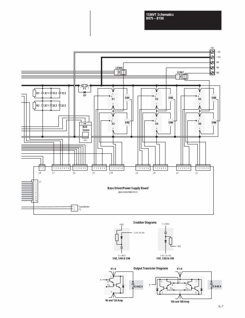
B075 – B1501336VT Schematics
S-7
C (X2, X4, X6)
E (– BUS)
+ BUS
– BUS
E (X1, X3, X5)
C (+ BUS)
SN2, SN4 & SN6 SN1, SN3 & SN5
Snubber Diagrams
12345678910
J1
21 1 2 3 4 5 6 7 8
J8 J7
TB1
– DC
+ DC
M1
M2
M3
1 2 3 4 5 6
J6
1 2 3 4 5 6
J5
1 2 3 4 5 6
J10
1 2 3 4 5 6
J4
1 2 3 4 5 6
J9
1 2 3 4 5 6
J3
1 2 3 4 5 6
J2
BSN5X5
C
E
B SN6X6
C
E
+–
LEM C
BSN3X3
C
E
B SN4X4
C
E
BSN1X1
C
E
B SN2X2
C
E
+–
LEM A
D1
F11 2
X1–6
C
BB
B X
E
C
B
B X
C
B
B X
X1–6
B
E E
C
E
Output Transistor Diagrams
12
TransformerT2
Base Driver/Power Supply Board(BASEDR/PWRSPLY)
96 and 124 Amp 156 and 180 Amp
(AC)
+ –
BUSSense
R1
R2
1C1 1C2 1C3
2C1 2C2 2C3
1C4-6C4 1C4-6C4

B075 – B1501336VT Schematics
S-8
This Page Intentionally Left Blank
Glossary
G-1
Glossary
+Bus: +Bus is the portion of the DC bus that is at positive (+) potential.
–Bus: –Bus is the portion of the DC bus that is at negative (–) potential.
AC Contactor: An alternating-current (AC) contactor establishes orinterrupts an AC Power circuit.
Adjustable Speed: An adjustable speed motor maintains the desiredoperating speed (set speed) regardless of the load.
Adjustable Speed Drive (Electrical): The adjustable speed drive consistsof the motor, drive controller, and (optional) local controls. The remoteoperator/drive controls may be either manual or automatic.
Ambient Temperature: Ambient temperature is the temperature of the airin which equipment is operated or stored.
Base Speed:Base speed is the manufacturer’s nameplate rating at whichthe motor develops rated horsepower (hp) at rated load and voltage. WithAC systems, base speed is commonly the point at which 60 Hz is appliedto the induction motor.
BR: Refer to Bridge Rectifier.
Braking: Braking stops an AC motor. Braking may be accomplished inany of the following ways:
1. Dynamic braking (AC drives) continues to excite the motor from thedrive, since AC motors do not have separate field excitation. Thiscauses a regenerative current to the drive’s intermediate bus todissipate the power returned. The brake resistor is usually switched bya transistor or other power switch controlled by the drive.
2. Regenerative braking is similar to dynamic braking but isaccomplished electronically. The generated power is returned to theline through the power converter. This power may also be dissipated aslosses in the converter (within its limitations).
3. A motor-mounted or separately-mounted brake is a positive-action,mechanical friction device. When power is removed, the brake isactivated.
Glossary
G-2
Breakaway Torque: Breakaway torque is the torque required to start amachine from standstill. Breakaway torque is always greater than thetorque needed to maintain motion.
Breakdown Torque: The breakdown torque of an AC motor is themaximum torque developed with rated voltage applied at rated frequency.
Bridge Rectifier (Diode, SCR): A diode bridge rectifier is anon-controlled, full-wave rectifier that produces a constant, rectified, DCvoltage. An SCR bridge rectifier is a full-wave rectifier with a DC outputthat can be controlled by switching on the gate control element.
Bridge Rectifier: A bridge rectifier is a full-wave rectifier that conductscurrent (through the load) in only one direction with respect to thealternating input voltage. AC applied to the input results in approximateDC at the output.
British Thermal Unit (BTU): A BTU is the quantity of heat required toraise one pound of water by one degree Fahrenheit.
BTU: Refer to British Thermal Unit.
Bus Sense:Bus Sense is a signal transducer that generates a signalproportional to the current in the drive’s DC bus. The control logic usesthis signal to sense the presence or absence of bus voltage.
CEMF: Refer to Counter Electromotive Force.
CMOS: Refer to Complimentary Metallic Oxide Semiconductor.
Cogging: Cogging is a condition in which a motor does not rotatesmoothly but steps or jerks from one position to another during shaftrotation. Cogging is most pronounced at low motor speeds and can causeobjectionable vibrations in the driven machinery.
Complimentary Metallic Oxide Semiconductor (CMOS): A CMOS isan integrated-circuit component for logic circuits. CMOS components usevery low power and have high switching rates. The CMOS is sensitive tohigh-voltage static discharges. Follow proper electrostatic dischargeprecautions to avoid damage to these components.
Constant Torque Range: Constant torque range is a speed range withinwhich a motor is capable of delivering a constant torque, subject to coolinglimitations of the motor.

Glossary
G-3
Constant Voltage Range:Constant voltage range applies to AC drives.This is the range of motor operation within which the drive’s outputvoltage is held constant as output frequency is varied. This range producesmotor performance similar to a DC drive’s constant horsepower (hp) range.
Constant Volts per Hertz (V/Hz): The V/Hz relationship exists in ACdrives where the output voltage is directly proportional to frequency. Thistype of operation produces constant rated torque as the motor’s speedvaries.
Continuous Duty: Continuous duty (CONT) refers to a motor that cancontinue to operate within insulation temperature limits after it has reachednormal operating (equilibrium) temperature.
Converter: A converter changes AC to DC, often through a diode rectifieror thyristor rectifier circuit. Converter also refers to the process ofchanging AC to DC to AC (e.g., adjustable frequency drive). A frequencyconverter, such as that found in an adjustable frequency drive, consists of arectifier, a DC intermediate circuit, an inverter, and a control unit.
Counter Electromotive Force (CEMF): CEMF is the energy per unit ofcharge converted into electrical form by a generator or a motor acting as agenerator. This energy is in opposition to, or counters, the applied voltage.
Current Limiting: Current limiting is an electronic process of limitingthe maximum current available to the motor. This is adjustable so that themotor’s maximum current can be limited. Current limiting can be preset toprotect both the motor and the control from extended overloads.
DC Boost: DC boost compensates for the voltage drop across theresistance of an AC motor circuit and the resulting reduction in torque.
DC Bus: DC bus is a drive’s power structure that transmits a rectified ACline power from the bridge rectifier to the output transistors.
Diode: A diode passes current in one direction but blocks current flow inthe reverse direction.
Drift: Drift is the deviation from the initial set speed with no load changeover a specific time. Normally, the drive must be operated for a specificwarm-up time at a specified ambient temperature before drift specificationsapply. Drift is normally caused by random changes in operatingcharacteristics of various control components.
Glossary
G-4
Drive Controller: A drive controller, sometimes called a variable speeddrive, controls the speed, torque, horsepower, and direction of an AC orDC motor.
Duty Cycle: A time interval occupied by starting, running, stopping andidling.
Dynamic Braking: Refer to Braking.
Efficiency: Efficiency is the ratio of useful output to input, expressed inpercentage. In motors, efficiency is the effectiveness with which a motorconverts electrical energy into mechanical energy.
Electrostatic Discharge (ESD):ESD is a static-electricity discharge thatmay damage drive components. Refer to the ESD precautions found in thismanual to guard against damage to drive components.
Enable: To enable is to allow an action or acceptance of data by applyingan appropriate signal to the appropriate input. Switch SW1, located on theProgramming and Display Board, allows you to enable and disable theprogramming functions of a drive.
Enclosure: An enclosure is the housing in which a motor control ismounted. Enclosures are available for most environmental conditions.
ESD: Refer to Electrostatic Discharge.
Floating Ground: Floating ground describes a circuit in which theelectrical common point is not at earth ground potential or the same groundpotential as the circuitry with which the floating ground circuit isassociated. Voltage differences can exist between the floating ground andearth ground.
Force: Force is the tendency to change the motion of an object with anexertion of energy from a separate source. Force is measured in pound-feet,ounce-inches, Newton-meters, or gram-centimeters.
Full Load Torque: The full-load torque of a motor is the torque necessaryto produce rated horsepower at full-load speed.
Gate: A gate is the control element of the SCR (silicon-controlledrectifier), commonly referred to as a thyristor. When a small positivevoltage is applied momentarily to the gate, the SCR conducts current.Current conduction continues after the gate signal is removed.
Glossary
G-5
GND Sense:GND sense, or ground sense, is a current transducer thatdetects an unequal or imbalanced current in the three-phase AC line or DCbus of the drive. The imbalance indicates an output ground fault condition.
Horsepower (hp): Horsepower is a measure of the amount of work amotor can perform in a given length of time. Refer to “Power” for kilowattequivalent.
Induction Motor: An induction motor is an alternating-current motor inwhich the primary winding on one member is connected to the powersource. A secondary winding on the other member carries the inducedcurrent. There is no physical electrical connection to the secondarywinding; its current is induced.
IEC: Just as the National Electrical Manufacturers Association goes byits acronym, “NEMA,” the International Electrotechnical Commission goesby “IEC.” And, like NEMA, IEC establishes and publishes mechanical andelectrical standards.
Inertia: Inertia is a measure of a body’s resistance to change in velocity,whether a body is at rest or moving at a constant velocity. The velocity canbe either linear or rotational. The moment of inertia (WK2) is the productof the object’s weight (W) and the square of the radius of gyration (K2).The radius of gyration is a measure of how the mass of the object isdistributed on the axis of rotation. The moment of inertia is expressed inlb-ft2 or Newton-meters2.
Integral-Horsepower Motor: An integral-horsepower motor is any motorbuilt in a frame having a continuous rating of 1 horsepower (hp) or more.
Interposing Relay: An interposing relay is a relay that accepts controlsignals of one logic level in order to provide isolated contact signals in acircuit operating at a different logic level.
Inverter: An inverter is an adjustable frequency AC drive or a particularsection of an AC drive. The inverter section uses the DC voltage from aprevious circuit stage (intermediate DC circuit) to produce an AC currentor voltage of a desired frequency.
ISO: The International Standards Organization (ISO) based in Geneva,Switzerland, has developed a series of global standards to define and“harmonize” product, service and business practices worldwide. The ISO9000 series, in particular, describes basic quality systems such as personneltraining guidelines and quality documentation procedures.
Glossary
G-6
Isolation Transformer: An Isolation Transformer electrically separatesthe drive from the AC power supply line. An isolation transformer:
1. Helps protect semiconductors from line voltage transients.
2. Reduces disturbances from other solid-state control equipment such asdrives without isolation transformers, time clock systems, electroniccounters, etc.
Jogging: Jogging is the momentary movement of a motor, usually throughmomentary closure of a circuit using a single pushbutton or contactelement.
Kinetic Energy: Kinetic energy is an object’s energy of motion.
LAD: Refer to Linear Acceleration/Deceleration.
LEM: LEM is a hall-effect current transducer that senses drive outputcurrent and generates a signal for the control logic.
Linear Acceleration/Deceleration (LAD): LAD is a circuit that controlsthe rate at which a motor accelerates to a set speed or decelerates to zerospeed. On most motor drives, this circuit can be adjusted and set toaccommodate particular applications.
Linearity: Linearity is a measure of how closely a characteristic follows astraight-line function.
Locked-Rotor Current: Locked-rotor current is a steady current takenfrom the power supply line current with the rotor at standstill, at ratedvoltage and frequency. This current is present when starting the motor andwhen the motor is under load.
Locked-Rotor Torque: Locked-rotor torque is the minimum torque amotor develops at rest for all angular positions of the rotor, with ratedvoltage applied at rated frequency.
Meggar Test: A Meggar test measures an insulation system’s resistance.This test passes a low current, high voltage through a motor’s windings andmeasures the resistance of the various insulation systems. Meggar testresults are usually expressed in megohms. Must be done with motordisconnected from drive.
MOV: Refer to Surge Protection.
Glossary
G-7
National Electrical Code (NEC): NEC is the code recommendations ofthe National Fire Protection Association. These codes are revised everythree years. City or state code regulations take precedence over, and maydiffer from, NEC code regulations.
National Electrical Manufacturer’s Association (NEMA): NEMA is anon-profit organization organized and supported by electrical equipmentand supply manufacturers. Some NEMA motor standards includehorsepower (hp) ratings, speeds, frame sizes and dimensions, torques, anddrive enclosures.
NEC: Refer to National Electrical Code.
NEMA: Refer to National Electrical Manufacturer’s Association.
Offset: Offset is the steady-state deviation of a controlled variable from afixed setpoint.
Op Amp: Refer to Operational Amplifier.
Open Loop: An open loop is a control system lacking feedback.
Operational Amplifier: An operational amplifier is usually a high-gainDC amplifier designed to be used with external circuit elements.
Overload Capacity: Overload capacity describes the ability of a drive towithstand currents beyond the system’s continuous rating. Overloadcapacity is usually expressed as a percentage of full-load current enduredin a specified time.
PC: Refer to Programmable Controller.
Plugging: Plugging is a method of motor braking that reverses either theline voltage polarity or the phase sequence. Plugging appliescounter-torque to a motor, exerting a retarding, or braking, force.
Pot: A pot is a potentiometer, or variable resistor.
Power Factor (Displacement):Displacement power factor is ameasurement of the time phase difference between the fundamental voltageand fundamental current in an AC circuit. It represents the cosine of thephase angle difference. Fp = cos (α– β)

Glossary
G-8
Power Factor (Distortion): Distortion power factor is a measurement ofthe ratio of the real power (kW) to the apparent power (kVA). Distortionpower factor takes into account harmonic voltage and current distortion aswell as voltage-to-current displacement.
Power: Power is work accomplished per unit of time. Power is measuredand expressed in horsepower (horsepower (hp)) or watts (W): 1horsepower (hp) = 33,000 ft-lb/min. = 746 W or 24,340 N-m/min = 1 kW.
Preform: Preform is a flexible material used between an electroniccomponent and the heat sink to which the component is attached. Preformprovides maximum heat dissipation from the component to the heat sink.
Preset Speed:Preset speed describes one or more fixed speeds at which adrive operates.
Programmable Controller: A programmable controller provides controllogic for machines and processes. A sequence of operations can be changedeasily through software programming.
Pull-In Torque: Pull-in torque is the maximum constant torque to which asynchronous motor accelerates into synchronism at rated voltage andfrequency.
Pull-Out Torque: Pull-out torque is the maximum running torque of asynchronous motor.
Pull-Up Torque: Pull-up torque is the torque required to accelerate a loadfrom standstill to full speed. Breakdown torque occurs at full speed.Pull-up torque is expressed in percentage of running torque. This torqueovercomes friction, windage, product loading, and inertial forces.
Pulse Width Modulating (PWM): PWM is an AC adjustable frequencydrive that accomplishes frequency and output control at the output(inverter) section of the drive. The drive’s voltage is always a constantamplitude, the average voltage of which is controlled through pulse widthmodulating.
PWM: Refer to Pulse Width Modulating.
Reactance: Reactance is the opposition (resistance) of a circuit orcomponent to an alternating current. Reactance is measured and expressedin ohms.
Glossary
G-9
Rectifier: A rectifier is an electrical device that transforms alternatingcurrent (AC) to direct current (DC).
Regeneration: Regeneration is the characteristic of a motor to act as agenerator when a rotor synchronous frequency is greater than the appliedfrequency (AC drives).
Regenerative Braking: Regenerative Braking slows or stops a motorthrough regeneration. Refer to Regeneration and Braking.
Resolution: Resolution is the smallest distinguishable increment intowhich a quantity can be divided. This increment may be shaft speed orshaft position by degrees. Resolution is also the degree to whichnearly-equal values of a quantity can be discriminated.
SCR: Refer to Silicon Controlled Rectifier.
Service Factor: A service factor is a number appearing on a motornameplate. This number indicates the extent to which a motor may beoverloaded above the nameplate rating without causing seriousdegradation. A motor with a 1.15 service factor can produce 15 percentgreater torque than a motor with a 1.0 service factor. A service factor mayalso apply to motors and gearmotors as a figure of merit used to adjustmeasured loads in an attempt to compensate for conditions which aredifficult to measure or define.
Set Speed:The set speed is the desired operating speed of a motor.
Shock Load: Shock loads affect clutches, brakes, and motors in systemsthat transmit high-peak loads. Shock loads are present in crushers,separators, grinders, conveyors, winches, and cranes.
Silicon Controlled Rectifier (SCR): The SCR is a solid-state switchsometimes referred to as a thyristor. The SCR has an anode, a cathode, anda control element called a gate. Because it can be turned on at will, theSCR provides controlled rectification. The SCR is small, lightweight, andcan rapidly switch large currents at high voltages.
Slip: Slip is the difference between the rotating magnetic field speed(synchronous speed) and the rotor speed of an AC induction motor. Slip isusually expressed as a percentage of synchronous speed.
Glossary
G-10
Speed Range:Speed range is the range of minimum and maximum speedwithin which a motor must operate under constant or variable torqueconditions. A 50:1 speed range for a motor with a maximum speed of 1800rpm means the motor must operate at a minimum speed of 36 rpm andremain within regulation specifications. Controllers are capable of widercontrollable speed ranges than motors because there is no thermallimitation, only electrical.
Speed Regulation:Speed regulation is a measurement of how accuratelya motor speed is maintained. Speed regulation is measured and expressedin percentage of change between full-load and no-load speeds.
Surge Protection: Surge protection is the process of absorbing andclipping voltage transients on an incoming AC power line or controlcircuit. Surge protectors include MOVs (Metal Oxide Varistors) andspecially designed R-C networks.
Synchronous Speed:Synchronous speed is the speed of the rotatingmagnetic field on an AC induction motor. The frequency applied to thestator and the number of magnetic poles present in each phase of the statorwindings determines synchronous speed. Synchronous speed ismathematically expressed as: sync speed (rpm) = 120 x applied freq.(Hz)/number of poles per phase.
Torque: Torque is a turning force applied to a shaft. This force tends tocause shaft rotation. Torque is normally measured and expressed inounce-inches (oz-in.) and pound-feet (lb-ft). Torque is the product of theforce applied to an object and the radius through which that force acts uponthe object.
Transducer: A transducer converts one energy form to another, such asmechanical energy to electrical energy. A transducer is also a device that,when actuated by signals form one or more systems or media, suppliesrelated signals to one or more other systems or media.
Transient: A transient is a momentary power deviation in an electrical ormechanical system.
Transistor: A transistor is a solid-state component. The terminals arecalled the emitter, the base, and the collector. Transistors amplify, switch,and control signals.

Glossary
G-11
Work: Work is a force needed to move an object or load over a distance.Work is measured in inch-ounces (in.-oz), gram-cemtimeters (gm-cm),foot-pounds (ft-lbs), or Newton-meters (N-m). Work = force timesdistance.

Glossary
G-12
This Page Intentionally Left Blank

Notes
N-1

Notes
N-2

Notes
N-3

Notes
N-4

Notes
N-5

Notes
N-6

Notes
N-7

Notes
N-8

Notes
N-9

Notes
N-10

Notes
N-11

Notes
N-12
CU
T AL
ON
G D
OTT
ED L
INE
✁We Want Our Manuals to be the Best!
You can help! Our manuals must meet the needs of you, the user. This is your opportunity to make sure they do just that.By filling out this form you can help us provide the most useful, thorough, and accurate manuals available. Please take afew minutes to tell us what you think. Then mail this form, FAX it, or send comments via E-Mail.FAX: to your local Allen-Bradley Sales Office or 414/242-8579E-Mail: via Internet to “[email protected]”
PUBLICATION NAME
PUBLICATION NUMBER, DATE AND PART NUMBER (IF PRESENT)
✓ CHECK THE FUNCTION THAT MOST CLEARLY DESCRIBES YOUR JOB.
� SUGGEST / RESPONSIBLE FOR THE PURCHASE OF EQUIPMENT � MAINTAIN / OPERATE PROGRAMMABLE MACHINERY
� DESIGN / IMPLEMENT ELECTRICAL SYSTEMS � TRAIN/EDUCATE MACHINE USERS
� SUPERVISE FLOOR OPERATIONS
✓ WHAT LEVEL OF EXPERIENCE DO YOU HAVE WITH EACH OF THE FOLLOWING PRODUCTS?
NONE LITTLE MODERATE EXTENSIVE
PROGRAMMABLE CONTROL � � � �
AC / DC DRIVES � � � �
PERSONAL COMPUTERS � � � �
NC / CNC CONTROLS � � � �
DATA COMMUNICATIONS / LAN � � � �
✓ RATE THE OVERALL QUALITY OF THIS MANUAL BY CIRCLING YOUR RESPONSE BELOW. (1) = POOR (5) = EXCELLENT
HELPFULNESS OF INDEX / TABLE OF CONTENTS 1 2 3 4 5
CLARITY 1 2 3 4 5
EASE OF USE 1 2 3 4 5
ACCURACY AND COMPLETENESS 1 2 3 4 5
QUALITY COMPARED TO OTHER COMPANIES’ MANUALS 1 2 3 4 5
QUALITY COMPARED TO OTHER ALLEN-BRADLEY MANUALS 1 2 3 4 5
✓ WHAT DID YOU LIKE MOST ABOUT THIS MANUAL?
✓ WHAT DID YOU LIKE LEAST ABOUT THIS MANUAL?
✓ PLEASE LIST ANY ERRORS YOU FOUND IN THIS MANUAL (REFERENCE PAGE, TABLE, OR FIGURE NUMBERS).
✓ DO YOU HAVE ANY ADDITIONAL COMMENTS?
✓ COMPLETE THE FOLLOWING.
NAME COMPANY
TITLE DEPARTMENT
STREET CITY STATE ZIP
TELEPHONE DATE
FOLD HERE
FOLD HERE
NO POSTAGENECESSARY
IF MAILEDIN THE
UNITED STATES
BUSINESS REPLY MAILPERMIT NO. 413 MEQUON, WI
POSTAGE WILL BE PAID BY ADDRESSEE
ALLEN-BRADLEYAttn: Marketing CommunicationsP.O. Box 760Mequon, WI 53092-9907
FIRST CLASS
Publication 1336-6.3 June, 1997 P/N 156052Supercedes 1336-6.3 — June, 1995 Copyright 1994, Allen-Bradley Company, Inc. Printed in USA