1336 plus ii adjustable frequency ac...
TRANSCRIPT
1336 PLUS IIAdjustableFrequencyAC Drive
Technical Data
2
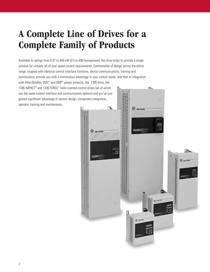
Available in ratings from 0.37 to 448 kW (0.5 to 600 horsepower), the drive helps to provide a single
solution for virtually all of your speed control requirements. Commonality of design across the entire
range, coupled with identical control interface functions, device communications, training and
maintenance, provide you with a tremendous advantage in your control needs. Add that to integration
with Allen-Bradley SMC™ and SMP™ power products, the 1305 drive, the
1336 IMPACT™ and 1336 FORCE™ field-oriented control drives (all of which
use the same control interface and communication options) and you’ve just
gained significant advantage in system design, component integration,
operator training and maintenance.
A Complete Line of Drives for aComplete Family of Products
3
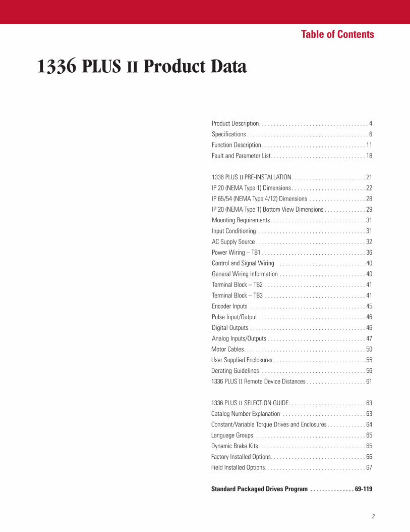
Table of Contents
1336 PLUS II Product Data
Product Description. . . . . . . . . . . . . . . . . . . . . . . . . . . . . . . . . . . . . 4
Specifications . . . . . . . . . . . . . . . . . . . . . . . . . . . . . . . . . . . . . . . . . 6
Function Description . . . . . . . . . . . . . . . . . . . . . . . . . . . . . . . . . . . 11
Fault and Parameter List. . . . . . . . . . . . . . . . . . . . . . . . . . . . . . . . 18
1336 PLUS II PRE-INSTALLATION. . . . . . . . . . . . . . . . . . . . . . . . . 21
IP 20 (NEMA Type 1) Dimensions . . . . . . . . . . . . . . . . . . . . . . . . . 22
IP 65/54 (NEMA Type 4/12) Dimensions . . . . . . . . . . . . . . . . . . . 28
IP 20 (NEMA Type 1) Bottom View Dimensions . . . . . . . . . . . . . . 29
Mounting Requirements . . . . . . . . . . . . . . . . . . . . . . . . . . . . . . . . 31
Input Conditioning. . . . . . . . . . . . . . . . . . . . . . . . . . . . . . . . . . . . . 31
AC Supply Source . . . . . . . . . . . . . . . . . . . . . . . . . . . . . . . . . . . . . 32
Power Wiring – TB1 . . . . . . . . . . . . . . . . . . . . . . . . . . . . . . . . . . . 36
Control and Signal Wiring . . . . . . . . . . . . . . . . . . . . . . . . . . . . . 40
General Wiring Information . . . . . . . . . . . . . . . . . . . . . . . . . . . . . 40
Terminal Block – TB2 . . . . . . . . . . . . . . . . . . . . . . . . . . . . . . . . . . 41
Terminal Block – TB3 . . . . . . . . . . . . . . . . . . . . . . . . . . . . . . . . . . 41
Encoder Inputs . . . . . . . . . . . . . . . . . . . . . . . . . . . . . . . . . . . . . . . 45
Pulse Input/Output . . . . . . . . . . . . . . . . . . . . . . . . . . . . . . . . . . . . 46
Digital Outputs . . . . . . . . . . . . . . . . . . . . . . . . . . . . . . . . . . . . . . . 46
Analog Inputs/Outputs . . . . . . . . . . . . . . . . . . . . . . . . . . . . . . . . . 47
Motor Cables. . . . . . . . . . . . . . . . . . . . . . . . . . . . . . . . . . . . . . . . . 50
User Supplied Enclosures . . . . . . . . . . . . . . . . . . . . . . . . . . . . . . . 55
Derating Guidelines. . . . . . . . . . . . . . . . . . . . . . . . . . . . . . . . . . . . 56
1336 PLUS II Remote Device Distances . . . . . . . . . . . . . . . . . . . . 61
1336 PLUS II SELECTION GUIDE. . . . . . . . . . . . . . . . . . . . . . . . . . 63
Catalog Number Explanation . . . . . . . . . . . . . . . . . . . . . . . . . . . . 63
Constant/Variable Torque Drives and Enclosures . . . . . . . . . . . . . 64
Language Groups. . . . . . . . . . . . . . . . . . . . . . . . . . . . . . . . . . . . . . 65
Dynamic Brake Kits . . . . . . . . . . . . . . . . . . . . . . . . . . . . . . . . . . . . 65
Factory Installed Options. . . . . . . . . . . . . . . . . . . . . . . . . . . . . . . . 66
Field Installed Options. . . . . . . . . . . . . . . . . . . . . . . . . . . . . . . . . . 67
Standard Packaged Drives Program . . . . . . . . . . . . . . . 69-119
4
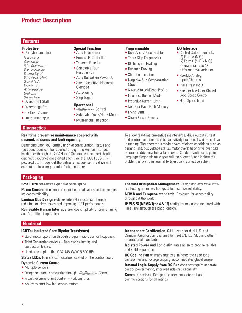
Product Description
Diagnostics
FeaturesProtective• Detection and Trip:
UndervoltageOvervoltageDrive OvercurrentOvertemperatureExternal SignalDrive Output ShortGround FaultEncoder LossAt temperatureLoad LossSingle Phase
• Overcurrent Stall• Overvoltage Stall• Six Drive Alarms• Fault Reset Input
Special Function• Auto Economizer• Process PI Controller• Traverse Function• Selectable Fault
Reset & Run• Auto Restart on Power Up• Speed Sensitive Electronic
Overload• Auto-tuning• Step Logic
Operational• Control• Selectable Volts/Hertz Mode• Multi-lingual selection
Programmable• Dual Accel/Decel Profiles• Three Skip Frequencies• DC Injection Braking• Dynamic Braking• Slip Compensation• Negative Slip Compensation
(Droop)• S Curve Accel/Decel Profile• Line Loss Restart Mode• Proactive Current Limit• Last Four Event Fault Memory• Flying Start• Seven Preset Speeds
I/O Interface• Control Output Contacts
(2) Form A (N.O.)(2) Form C (N.O. - N.C.)Programmable to 17different drive variables.
• Flexible AnalogInputs/Outputs
• Pulse Train Input• Encoder Feedback Closed
Loop Speed Control• High Speed Input
Real time preventive maintenance coupled with customized status and fault reporting.Depending upon your particular drive configuration, status andfault conditions can be reported through the Human InterfaceModule or through the SCANport™ Communications Port. Faultdiagnostic routines are started each time the 1336 PLUS II ispowered up. Throughout the entire run sequence, the drive willcontinue to look for potential fault conditions.
To allow real-time preventive maintenance, drive output currentand control conditions can be selectively monitored while the driveis running. The operator is made aware of alarm conditions such ascurrent limit, bus voltage status, motor overload or drive overloadbefore the drive reaches a fault level. Should a fault occur, plainlanguage diagnostic messages will help identify and isolate theproblem, allowing personnel to take quick, corrective action.
ElectricalIGBT’s (Insulated Gate Bipolar Transistors)• Quiet motor operation through programmable carrier frequency.• Third Generation devices – Reduced switching and
conduction losses.• Used on complete line 0.37-448 kW (0.5-600 HP).Status LEDs. Four status indicators located on the control board.Dynamic Current Control• Multiple sensors.• Exceptional torque production through Control.• Proactive current limit control – Reduces trips.• Ability to start low inductance motors.
Independent Certification. C-UL Listed for dual U.S. andCanadian Certification. Designed to meet EN, IEC, VDE and otherinternational standards.Isolated Power and Logic eliminates noise to provide reliableand stable operation.DC Cooling Fan on many ratings eliminates the need for atransformer and voltage tapping; accommodates global usage.Internal Logic Supply from DC Bus does not require separatecontrol power wiring, improved ride-thru capability.Communications. Designed to accommodate on-boardcommunications for all ratings.
PackagingSmall size conserves expensive panel space.Planer Construction eliminates most internal cables and connectors.Increases reliability.Laminar Bus Design reduces internal inductance, therebyreducing snubber losses and improving IGBT performance.Removable Human Interface provides simplicity of programmingand flexibility of operation.
Thermal Dissipation Management. Design and extensive infra-red testing minimizes hot spots to maximize reliability.NEMA and European standards. Designed for acceptabilitythroughout the world.IP 65 & 54 (NEMA Type 4 & 12) configurations accommodated with“heat sink through the back” design.
5
Product Description
DriveTools, PLC, SLC and SCANport are registered trademarks of Rockwell Automation.
The 1336 PLUS IIThe standard solution to your application needs.The 1336 PLUS II provides ratings from 0.37-448 kW (0.5-600 HP)in three voltage ranges – 200-240V AC, 380-480V AC and 500-600V AC. The 1336 PLUS II is a micro-processor basedadjustable frequency PWM AC drive. Its advanced design provides
exceptional reliability when controlling 3-phase motors. The outputcan be tuned to provide optimum performance for virtually any loadcondition. Selectable or V/Hz operation providesoutstanding motor control.
Simplicity
Design and programming simplicity is evident in:• Condensed packaging that allows for easy mounting,
installation and wiring in all types of applications.• Common assembly parts that reduces the need to stock
a multitude of parts.• Easy to program parameters that are organized in a group
and element structure for quick access to related functions.• Simple tuning for optimum torque performance.
• An easy to read Supertwist Liquid Crystal Display gives 2 lines of 16 characters each for easy “one finger” programming and drive monitoring.
• Serial communications that provide easy integration and access to peripheral equipment – Fully compatible with all Allen-Bradley PLC® or SLC™ equipment.
• Common options that are used throughout the entire family of Drives.
FlexibilityDigitally programmable to help provide precise andaccurate control.The l336 PLUS II uses digitally programmable features to achieveprecise and consistently accurate control, setup and operation. The drive can be programmed locally from the Human InterfaceModule or through a serial communications port using a PLC, SLC,or DriveTools™ programming software.
Configurable I/O allows simple connection to manycustomer preformed control schemes.Control inputs and outputs can be programmed to meet nearlyevery application requirement.
PerformancePowerful algorithms provide unparalleledperformance.Starting acceleration and running torque in excess of 250%combined with a constant torque speed range of 120:1 allow the1336 PLUS II to handle the tough applications other drives can’t.
6
Specifications
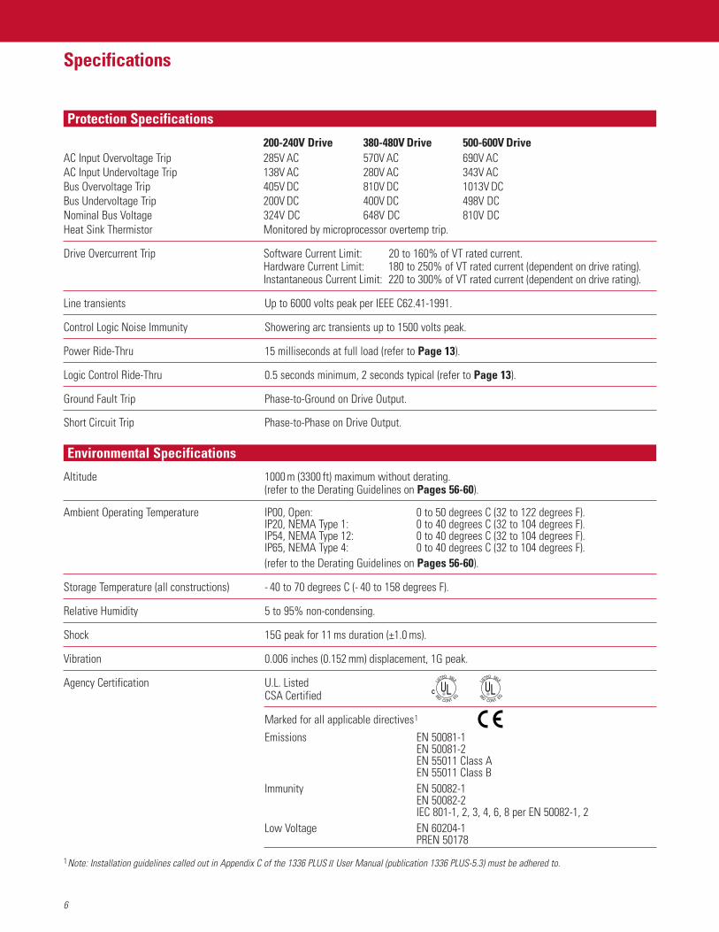
200-240V Drive 380-480V Drive 500-600V DriveAC Input Overvoltage Trip 285V AC 570V AC 690V ACAC Input Undervoltage Trip 138V AC 280V AC 343V ACBus Overvoltage Trip 405V DC 810V DC 1013V DCBus Undervoltage Trip 200V DC 400V DC 498V DCNominal Bus Voltage 324V DC 648V DC 810V DCHeat Sink Thermistor Monitored by microprocessor overtemp trip.
Drive Overcurrent Trip Software Current Limit: 20 to 160% of VT rated current.Hardware Current Limit: 180 to 250% of VT rated current (dependent on drive rating).Instantaneous Current Limit: 220 to 300% of VT rated current (dependent on drive rating).
Line transients Up to 6000 volts peak per IEEE C62.41-1991.
Control Logic Noise Immunity Showering arc transients up to 1500 volts peak.
Power Ride-Thru 15 milliseconds at full load (refer to Page 13).
Logic Control Ride-Thru 0.5 seconds minimum, 2 seconds typical (refer to Page 13).
Ground Fault Trip Phase-to-Ground on Drive Output.
Short Circuit Trip Phase-to-Phase on Drive Output.
Altitude 1000 m (3300 ft) maximum without derating.(refer to the Derating Guidelines on Pages 56-60).
Ambient Operating Temperature IP00, Open: 0 to 50 degrees C (32 to 122 degrees F).IP20, NEMA Type 1: 0 to 40 degrees C (32 to 104 degrees F).IP54, NEMA Type 12: 0 to 40 degrees C (32 to 104 degrees F).IP65, NEMA Type 4: 0 to 40 degrees C (32 to 104 degrees F).(refer to the Derating Guidelines on Pages 56-60).
Storage Temperature (all constructions) - 40 to 70 degrees C (- 40 to 158 degrees F).
Relative Humidity 5 to 95% non-condensing.
Shock 15G peak for 11 ms duration (±1.0 ms).
Vibration 0.006 inches (0.152 mm) displacement, 1G peak.
Agency Certification U.L. ListedCSA Certified
Marked for all applicable directives1
Emissions EN 50081-1EN 50081-2EN 55011 Class AEN 55011 Class B
Immunity EN 50082-1EN 50082-2IEC 801-1, 2, 3, 4, 6, 8 per EN 50082-1, 2
Low Voltage EN 60204-1PREN 50178
ULC
QETNOCDNI
6L65DETSIL
UL
QETNOCDNI
6L65DETSIL
1Note: Installation guidelines called out in Appendix C of the 1336 PLUS II User Manual (publication 1336 PLUS-5.3) must be adhered to.
Protection Specifications
Environmental Specifications
7
Specifications
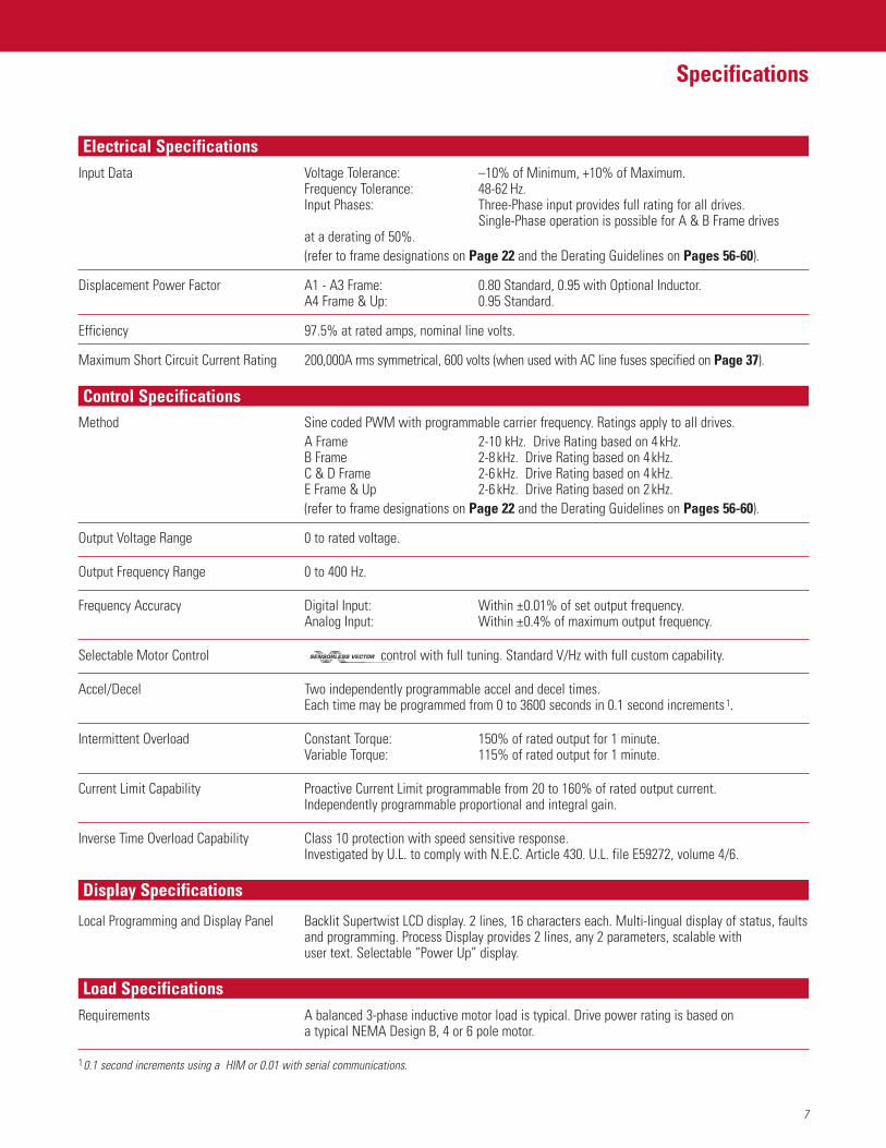
Input Data Voltage Tolerance: –10% of Minimum, +10% of Maximum.Frequency Tolerance: 48-62 Hz.Input Phases: Three-Phase input provides full rating for all drives.
Single-Phase operation is possible for A & B Frame drives at a derating of 50%.(refer to frame designations on Page 22 and the Derating Guidelines on Pages 56-60).
Displacement Power Factor A1 - A3 Frame: 0.80 Standard, 0.95 with Optional Inductor.A4 Frame & Up: 0.95 Standard.
Efficiency 97.5% at rated amps, nominal line volts.
Maximum Short Circuit Current Rating 200,000A rms symmetrical, 600 volts (when used with AC line fuses specified on Page 37).
Method Sine coded PWM with programmable carrier frequency. Ratings apply to all drives.A Frame 2-10 kHz. Drive Rating based on 4 kHz.B Frame 2-8 kHz. Drive Rating based on 4 kHz.C & D Frame 2-6 kHz. Drive Rating based on 4 kHz.E Frame & Up 2-6 kHz. Drive Rating based on 2 kHz.(refer to frame designations on Page 22 and the Derating Guidelines on Pages 56-60).
Output Voltage Range 0 to rated voltage.
Output Frequency Range 0 to 400 Hz.
Frequency Accuracy Digital Input: Within ±0.01% of set output frequency.Analog Input: Within ±0.4% of maximum output frequency.
Selectable Motor Control control with full tuning. Standard V/Hz with full custom capability.
Accel/Decel Two independently programmable accel and decel times.Each time may be programmed from 0 to 3600 seconds in 0.1 second increments1.
Intermittent Overload Constant Torque: 150% of rated output for 1 minute.Variable Torque: 115% of rated output for 1 minute.
Current Limit Capability Proactive Current Limit programmable from 20 to 160% of rated output current. Independently programmable proportional and integral gain.
Inverse Time Overload Capability Class 10 protection with speed sensitive response.Investigated by U.L. to comply with N.E.C. Article 430. U.L. file E59272, volume 4/6.
Local Programming and Display Panel Backlit Supertwist LCD display. 2 lines, 16 characters each. Multi-lingual display of status, faultsand programming. Process Display provides 2 lines, any 2 parameters, scalable with user text. Selectable “Power Up” display.
Requirements A balanced 3-phase inductive motor load is typical. Drive power rating is based on a typical NEMA Design B, 4 or 6 pole motor.
10.1 second increments using a HIM or 0.01 with serial communications.
Electrical Specifications
Control Specifications
Display Specifications
Load Specifications
8
Specifications
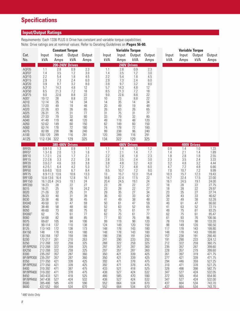
Requirements: Each 1336 PLUS II Drive has constant and variable torque capabilities.Note: Drive ratings are at nominal values. Refer to Derating Guidelines on Pages 56-60.
Constant Torque Variable Torque Variable TorqueCat. Input Input Output Output Input Input Output Output Input Input Output OutputNo. kVA Amps kVA Amps kVA Amps kVA Amps kVA Amps kVA Amps
200-240V Drives 240V DrivesAQF05 1.1 2.8 0.9 2.3 1.1 2.8 0.9 2.3AQF07 1.4 3.5 1.2 3.0 1.4 3.5 1.2 3.0AQF10 2.2 5.4 1.8 4.5 2.2 5.4 1.8 4.5AQF15 2.9 7.3 2.4 6.0 2.9 7.3 2.4 6.0AQF20 3.9 9.7 3.2 8.0 3.9 9.7 3.2 8.0AQF30 5.7 14.3 4.8 12 5.7 14.3 4.8 12AQF50 8.5 21.3 7.2 18 8.5 21.3 7.2 18AQF75 9.0 22.6 8.8 22 9.0 22.6 8.8 22A007 10-12 28 8.8 22 10 23 8.8 22A010 12-14 35 14 34 14 35 14 34A015 17-20 49 19 48 20 49 19 48A020 22-26 63 26 65 26 63 26 65A025 26-31 75 31 77 31 75 31 77A030 27-33 79 32 80 33 79 32 80A040 41-49 119 48 120 49 119 48 120A050 52-62 149 60 150 62 149 60 150A060 62-74 178 72 180 74 178 72 180A075 82-99 238 96 240 99 238 96 240A100 100-120 289 116 291 120 289 116 291A125 112-134 322 129 325 134 322 129 325
380-480V Drives 480V Drives 400V DrivesBRF05 0.9-1.0 1.3 0.9 1.1 1.1 1.4 1.0 1.2 0.9 1.4 1.0 1.33BRF07 1.3-1.6 2.0 1.3 1.6 1.7 2.1 1.4 1.7 1.4 2.1 1.4 1.89BRF10 1.7-2.1 2.6 1.7 2.1 2.2 2.8 1.8 2.3 1.8 2.8 1.8 2.55BRF15 2.2-2.6 3.3 2.2 2.8 2.8 3.5 2.4 3.0 2.3 3.5 2.4 3.33BRF20 3.0-3.7 4.6 3.0 3.8 3.8 4.8 3.2 4.0 3.2 4.8 3.2 4.44BRF30 4.2-5.1 6.4 4.2 5.3 5.7 7.2 4.8 6.0 4.7 7.2 4.8 6.66BRF50 6.6-8.0 10.0 6.7 8.4 8.5 10.7 7.2 9.0 7.0 10.7 7.2 9.99BRF75 8.9-11.3 13.6 10.6 13.3 13 15.7 12.3 15.4 10.3 15.7 12.3 19.43BRF100 10.8-13.6 16.4 12.8 16.1 18.6 22.4 17.5 22 14.7 22.4 17.5 22.00BRF150 16.1-20.4 24.5 19.1 24 20.4 24.5 19.1 24 16.1 24.5 19.1 24.00BRF200 18-23 28 22 27 23 28 22 27 18 28 22 27.75B015 16-21 25 19 24.2 23 28 22 27 18 28 22 29.97B020 21-26 32 25 31 29 35 27 34 23 35 27 37.74B025 26-33 40 31 39 36 43 33 42 28 43 33 46.62B030 30-38 46 36 45 41 49 38 48 32 49 38 53.28BX040 40-50 61 47 59 50 61 47 59 40 61 47 66.60B040 38-48 58 48 60 52 63 52 65 41 63 52 72.15B050 48-60 73 60 75 62 75 61 77 49 75 61 83.25BX0601 62 75 61 77 62 75 61 77 62 75 61 85.47B060 54-68 82 68 85 77 93 76 96 61 93 76 106.56B075 69-87 105 84 106 99 119 96 120 78 119 98 133.20B100 90-114 137 110 138 124 149 120 150 98 149 120 166.50B125 113-143 172 138 173 148 178 143 180 117 178 143 199.80BX150 148 178 143 180 148 178 143 180 148 178 143 199.80B150 130-164 197 159 199 198 238 191 240 157 238 191 266.40B200 172-217 261 210 263 241 290 233 292 191 290 233 324.12B250 212-268 322 259 325 268 322 259 325 212 322 259 360.75BP/BPR250 212-268 322 259 325 297 357 287 360 235 357 287 399.60BX250 212-268 322 259 325 297 357 287 360 228 357 279 399.60B300 235-297 357 287 360 350 421 339 425 261 397 319 471.75BP/BPR300 235-297 357 287 360 350 421 339 425 277 421 339 471.75B350 277-350 421 339 425 392 471 378 475 294 446 359 527.25BP/BPR350 277-350 421 339 425 392 471 378 475 310 471 378 527.25B400 310-392 471 387 475 433 521 418 525 326 496 398 582.75BP/BPR400 310-392 471 378 475 438 527 424 532 347 527 424 532.05B450 343-433 521 418 525 486 585 470 590 372 565 454 654.90BP/BPR450 347-438 527 424 532 438 527 424 532 347 527 424 532.00B500 385-486 585 470 590 552 664 534 670 437 664 534 743.70B600 437-552 664 534 670 552 664 534 670 437 664 534 743.70
1480 Volts Only.
Input/Output Ratings
9
Specifications
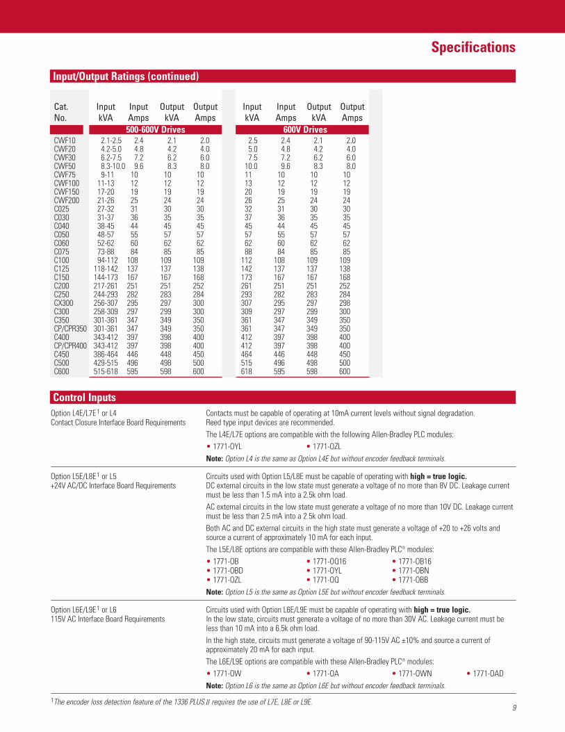
Constant Torque Variable TorqueCat. Input Input Output Output Input Input Output OutputNo. kVA Amps kVA Amps kVA Amps kVA Amps
500-600V Drives 600V DrivesCWF10 2.1-2.5 2.4 2.1 2.0 2.5 2.4 2.1 2.0CWF20 4.2-5.0 4.8 4.2 4.0 5.0 4.8 4.2 4.0CWF30 6.2-7.5 7.2 6.2 6.0 7.5 7.2 6.2 6.0CWF50 8.3-10.0 9.6 8.3 8.0 10.0 9.6 8.3 8.0CWF75 9-11 10 10 10 11 10 10 10CWF100 11-13 12 12 12 13 12 12 12CWF150 17-20 19 19 19 20 19 19 19CWF200 21-26 25 24 24 26 25 24 24C025 27-32 31 30 30 32 31 30 30C030 31-37 36 35 35 37 36 35 35C040 38-45 44 45 45 45 44 45 45C050 48-57 55 57 57 57 55 57 57C060 52-62 60 62 62 62 60 62 62C075 73-88 84 85 85 88 84 85 85C100 94-112 108 109 109 112 108 109 109C125 118-142 137 137 138 142 137 137 138C150 144-173 167 167 168 173 167 167 168C200 217-261 251 251 252 261 251 251 252C250 244-293 282 283 284 293 282 283 284CX300 256-307 295 297 300 307 295 297 298C300 258-309 297 299 300 309 297 299 300C350 301-361 347 349 350 361 347 349 350CP/CPR350 301-361 347 349 350 361 347 349 350C400 343-412 397 398 400 412 397 398 400CP/CPR400 343-412 397 398 400 412 397 398 400C450 386-464 446 448 450 464 446 448 450C500 429-515 496 498 500 515 496 498 500C600 515-618 595 598 600 618 595 598 600
Option L4E/L7E1 or L4 Contacts must be capable of operating at 10mA current levels without signal degradation.Contact Closure Interface Board Requirements Reed type input devices are recommended.
The L4E/L7E options are compatible with the following Allen-Bradley PLC modules:• 1771-OYL • 1771-OZLNote: Option L4 is the same as Option L4E but without encoder feedback terminals.
Option L5E/L8E1 or L5 Circuits used with Option L5/L8E must be capable of operating with high = true logic.+24V AC/DC Interface Board Requirements DC external circuits in the low state must generate a voltage of no more than 8V DC. Leakage current
must be less than 1.5 mA into a 2.5k ohm load.AC external circuits in the low state must generate a voltage of no more than 10V DC. Leakage currentmust be less than 2.5 mA into a 2.5k ohm load.Both AC and DC external circuits in the high state must generate a voltage of +20 to +26 volts andsource a current of approximately 10 mA for each input.The L5E/L8E options are compatible with these Allen-Bradley PLC® modules:• 1771-OB • 1771-OQ16 • 1771-OB16• 1771-OBD • 1771-OYL • 1771-OBN• 1771-OZL • 1771-OQ • 1771-OBBNote: Option L5 is the same as Option L5E but without encoder feedback terminals.
Option L6E/L9E1 or L6 Circuits used with Option L6E/L9E must be capable of operating with high = true logic.115V AC Interface Board Requirements In the low state, circuits must generate a voltage of no more than 30V AC. Leakage current must be
less than 10 mA into a 6.5k ohm load.In the high state, circuits must generate a voltage of 90-115V AC ±10% and source a current ofapproximately 20 mA for each input.The L6E/L9E options are compatible with these Allen-Bradley PLC® modules:• 1771-OW • 1771-OA • 1771-OWN • 1771-OADNote: Option L6 is the same as Option L6E but without encoder feedback terminals.
1The encoder loss detection feature of the 1336 PLUS II requires the use of L7E, L8E or L9E.
Control Inputs
Input/Output Ratings (continued)
10
Specifications
Analog Option Card Slot A No Option Card Two single-ended, non-isolated inputs configurable for a potentiometer reference, 0-10V, or 0-20 mA signal
LA2 Dual Isolated Input CardLA6 Isolated Bipolar/Isolated Thermistor Input CardLA7 Isolated Bipolar Input/Isolated Input Card
Analog Option Card Slot B No Option Card One single-ended, non-isolated input configurable for apotentiometer reference, 0-10V, or 0-20 mA signal and two single-ended, non-isolated 0-10V only outputs.
LA1 Dual Analog Output CardLA3 Dual Isolated Output CardLA4 Isolated Input/Isolated Output CardLA5 Analog Output/Pulse Output/Pulse Input Card
Digital Input Specifications Frequency Resolution:Maximum frequency programmed divided by 32767 (15 bits).60 Hz – 0.0018 Hz.100 Hz – 0.003 Hz.400 Hz – 0.012 Hz.
Contact Outputs 115V AC, 30V DC – 5.0 Amp Resistive – 2.0 Amp Inductive.(2) Form C Contacts.(2) Form A Contacts.All contacts are fully programmable for closure relative to 17 different drive variablesselected through the “CR1-4 Out Select” parameters.
Requirements Line Driver Encoder 5V DC or 8-15V DC Output.Minimum Current – 10mA per Channel.Quadrature or Pulse.Single Ended or Differential.Maximum Input Frequency – 250 kHz
Remote I/O Single drop remote I/O to Allen-Bradley PLCs and SLC 500. Supports full block transfer andlink mode discrete transfer.
RS232/422/485 DFI Protocol – DH485 Protocol – Customer Specific Protocol.
DeviceNet™ DeviceNet to SCANport module – Available for all drive ratings.
Flex™ I/O Flex I/O to SCANport module – Available for all drive ratings.
SLC SLC to SCANport module – Available for all drive ratings.
Flexible Analog Inputs and Outputs
Digital Inputs and Outputs
Encoder Inputs
Serial Communications Options

11
Function Description
New vector control adds exceptional torque performance to the 1336 PLUS II.This powerful algorithm provides the following performance enhancements.• Outstanding low speed torque at speeds as low as 15 rpm, providing a 120:1
constant torque speed range.• Improved acceleration control can provide up to 250% breakaway/acceleration torque to move the toughest loads with ease.• Solid “out-of-the-box” performance. Enhanced performance can be gained by programming the setup parameters with actual motor
nameplate values. Optimum results can be achieved by programming the actual amps required to generate no load flux and the actualvoltage needed for IR compensation. If these values are not known, setup procedures can determine the exact values.
• A fast accel mode is provided. Disabling the Adaptive Current Limit feature provides the lowest possible acceleration time for low inertia applications.
• A fast flux-up mode is programmable to aid in acceleration with large motors.• Selectable Volts/Hertz modes are also available. When selected, they provide full functionality
including Start Boost and Run Boost, Boost Slope and “Full Custom” V/Hz operation.
Simple process control, monitoring a feedback device and adjusting drive output according to feedback requirements can be accomplishedwith the 1336 PLUS II Proportional and integral gain adjustments plus feedback scaling, error inversion, output clamping and integratorreset functions allow the Process PI function to control the output of the 1336 PLUS II based on the PI reference (setpoint) and the PI feedback. If the feedback device indicates that the process is moving away from the desired setpoint, the PI software responds byadjusting the drive output until the feedback again equals the setpoint. Selectable inputs provide “auto/manual” capability for open loop threading operation. Programmable presets and preloads assure smooth transitions.
PI Reference
PI ReferenceSelect
pi reference
∑ ∑
√
PI Config.sqrt_fdbkPI Config.inv_error PI Config.reset_int
PI Feedback
Freq Command
PI Error
Master Frequency Reference
Process KIs
Process KP
Integral Term = 0
PI + Clamp
PI – Clamp
PI Output
SpeedAdder
Output Frequency
SpeedCommand
SpeedRamp
pi feedback
PI FeedbackSelect
ComputeSpeed
AccelControl
+ –1–
+
+
∑
PI Config.zero_clamp
speed ramp>0
++
PI Output
+32767
Parameter 65
–32767
–32767
+32767
0
0
Sensorless Vector Motor Control
Process PI Control
12
Function Description
0
100
99
98
97
% of Speed
96
9510 20 30 40 50
% of Load
60 70 80 90 100
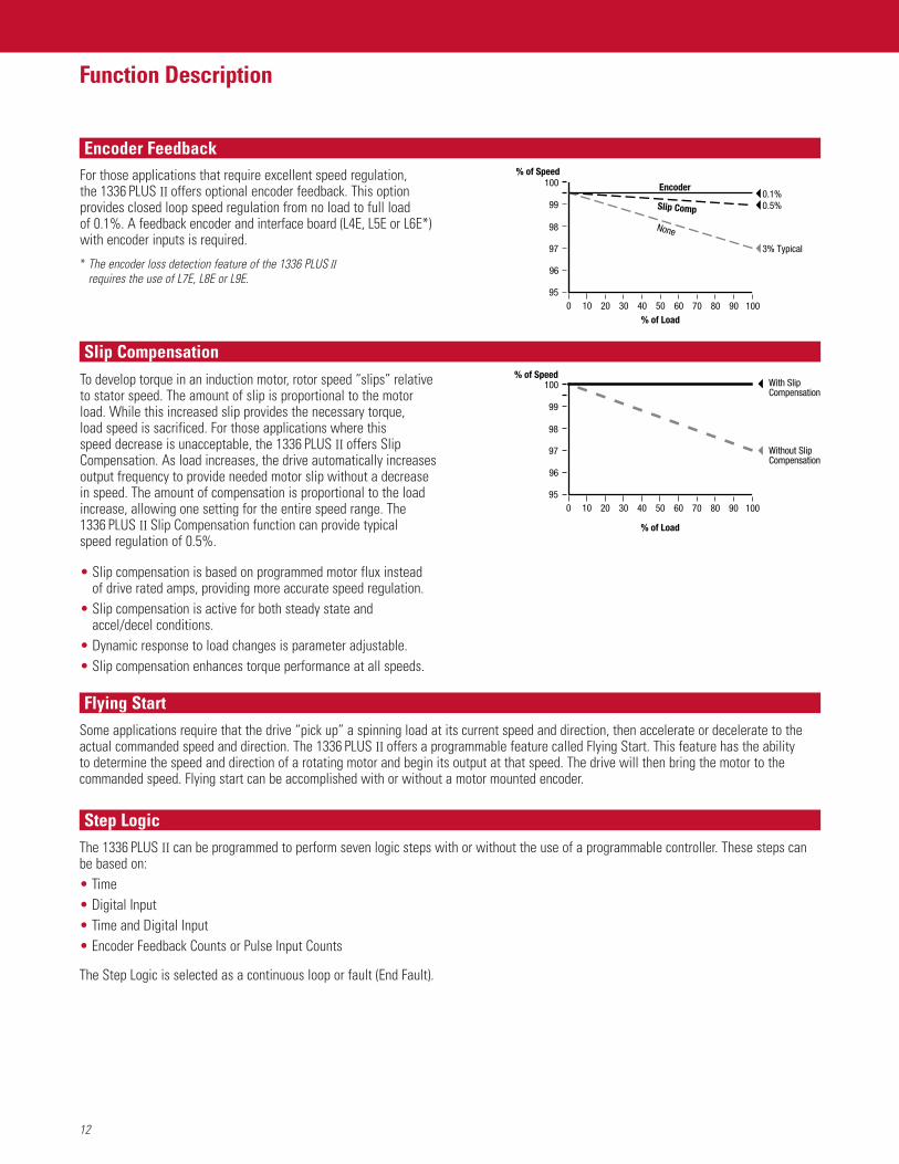
With Slip Compensation
Without Slip Compensation
For those applications that require excellent speed regulation, the 1336 PLUS II offers optional encoder feedback. This optionprovides closed loop speed regulation from no load to full load of 0.1%. A feedback encoder and interface board (L4E, L5E or L6E*)with encoder inputs is required.
* The encoder loss detection feature of the 1336 PLUS II requires the use of L7E, L8E or L9E.
To develop torque in an induction motor, rotor speed “slips” relativeto stator speed. The amount of slip is proportional to the motorload. While this increased slip provides the necessary torque, load speed is sacrificed. For those applications where this speed decrease is unacceptable, the 1336 PLUS II offers SlipCompensation. As load increases, the drive automatically increasesoutput frequency to provide needed motor slip without a decreasein speed. The amount of compensation is proportional to the loadincrease, allowing one setting for the entire speed range. The 1336 PLUS II Slip Compensation function can provide typical speed regulation of 0.5%.
• Slip compensation is based on programmed motor flux instead of drive rated amps, providing more accurate speed regulation.
• Slip compensation is active for both steady state and accel/decel conditions.
• Dynamic response to load changes is parameter adjustable.• Slip compensation enhances torque performance at all speeds.
0
Encoder100
99
98
97
% of Speed
96
95
None
10 20 30 40 50% of Load
60 70 80 90 100
Slip Comp 0.5%0.1%
3% Typical
Some applications require that the drive “pick up” a spinning load at its current speed and direction, then accelerate or decelerate to theactual commanded speed and direction. The 1336 PLUS II offers a programmable feature called Flying Start. This feature has the ability to determine the speed and direction of a rotating motor and begin its output at that speed. The drive will then bring the motor to thecommanded speed. Flying start can be accomplished with or without a motor mounted encoder.
Encoder Feedback
Slip Compensation
Flying Start
The 1336 PLUS II can be programmed to perform seven logic steps with or without the use of a programmable controller. These steps canbe based on:• Time• Digital Input• Time and Digital Input• Encoder Feedback Counts or Pulse Input Counts
The Step Logic is selected as a continuous loop or fault (End Fault).
Step Logic
13
Function Description
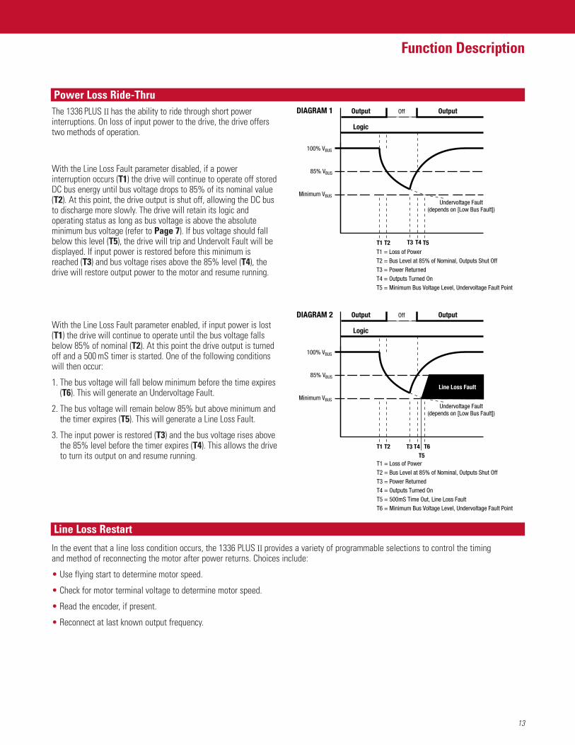
The 1336 PLUS II has the ability to ride through short powerinterruptions. On loss of input power to the drive, the drive offerstwo methods of operation.
Diagram 1With the Line Loss Fault parameter disabled, if a powerinterruption occurs (T1) the drive will continue to operate off storedDC bus energy until bus voltage drops to 85% of its nominal value(T2). At this point, the drive output is shut off, allowing the DC busto discharge more slowly. The drive will retain its logic andoperating status as long as bus voltage is above the absoluteminimum bus voltage (refer to Page 7). If bus voltage should fallbelow this level (T5), the drive will trip and Undervolt Fault will bedisplayed. If input power is restored before this minimum isreached (T3) and bus voltage rises above the 85% level (T4), thedrive will restore output power to the motor and resume running.
Diagram 2With the Line Loss Fault parameter enabled, if input power is lost(T1) the drive will continue to operate until the bus voltage fallsbelow 85% of nominal (T2). At this point the drive output is turnedoff and a 500 mS timer is started. One of the following conditionswill then occur:
1. The bus voltage will fall below minimum before the time expires(T6). This will generate an Undervoltage Fault.
2. The bus voltage will remain below 85% but above minimum andthe timer expires (T5). This will generate a Line Loss Fault.
3. The input power is restored (T3) and the bus voltage rises abovethe 85% level before the timer expires (T4). This allows the driveto turn its output on and resume running.
In the event that a line loss condition occurs, the 1336 PLUS II provides a variety of programmable selections to control the timing and method of reconnecting the motor after power returns. Choices include:
• Use flying start to determine motor speed.
• Check for motor terminal voltage to determine motor speed.
• Read the encoder, if present.
• Reconnect at last known output frequency.
OutputDIAGRAM 1
T1T1 = Loss of PowerT2 = Bus Level at 85% of Nominal, Outputs Shut OffT3 = Power ReturnedT4 = Outputs Turned OnT5 = Minimum Bus Voltage Level, Undervoltage Fault Point
T2 T4 T5T3
Logic
OutputOff
100% VBUS
85% VBUS
Minimum VBUS
Undervoltage Fault(depends on [Low Bus Fault])
Output
T1
T1 = Loss of PowerT2 = Bus Level at 85% of Nominal, Outputs Shut OffT3 = Power ReturnedT4 = Outputs Turned OnT5 = 500mS Time Out, Line Loss FaultT6 = Minimum Bus Voltage Level, Undervoltage Fault Point
T2 T4 T6T5
T3
Logic
OutputOff
100% VBUS
85% VBUS
Minimum VBUS
Undervoltage Fault(depends on [Low Bus Fault])
Line Loss Fault
DIAGRAM 2
Power Loss Ride-Thru
Line Loss Restart
14
Function Description
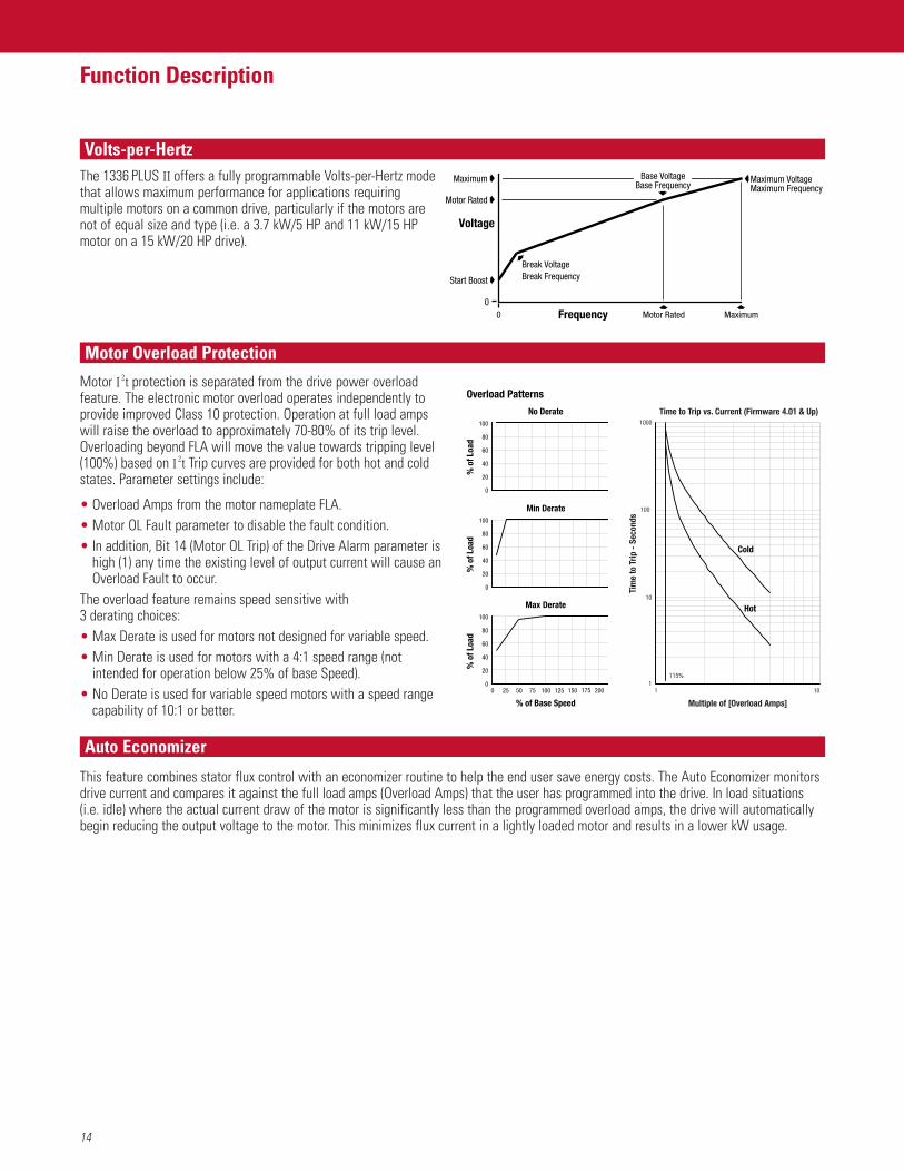
The 1336 PLUS II offers a fully programmable Volts-per-Hertz modethat allows maximum performance for applications requiringmultiple motors on a common drive, particularly if the motors arenot of equal size and type (i.e. a 3.7 kW/5 HP and 11 kW/15 HPmotor on a 15 kW/20 HP drive).
Motor I2t protection is separated from the drive power overloadfeature. The electronic motor overload operates independently toprovide improved Class 10 protection. Operation at full load ampswill raise the overload to approximately 70-80% of its trip level.Overloading beyond FLA will move the value towards tripping level(100%) based on I2t Trip curves are provided for both hot and coldstates. Parameter settings include:
• Overload Amps from the motor nameplate FLA.• Motor OL Fault parameter to disable the fault condition.• In addition, Bit 14 (Motor OL Trip) of the Drive Alarm parameter is
high (1) any time the existing level of output current will cause anOverload Fault to occur.
The overload feature remains speed sensitive with 3 derating choices:• Max Derate is used for motors not designed for variable speed.• Min Derate is used for motors with a 4:1 speed range (not
intended for operation below 25% of base Speed).• No Derate is used for variable speed motors with a speed range
capability of 10:1 or better.
This feature combines stator flux control with an economizer routine to help the end user save energy costs. The Auto Economizer monitorsdrive current and compares it against the full load amps (Overload Amps) that the user has programmed into the drive. In load situations(i.e. idle) where the actual current draw of the motor is significantly less than the programmed overload amps, the drive will automaticallybegin reducing the output voltage to the motor. This minimizes flux current in a lightly loaded motor and results in a lower kW usage.
Min Derate
0
80
100
60
40
20
% o
f Loa
d%
of L
oad
% o
f Loa
d
No Derate
0
80
100
60
40
20
% of Base Speed
Max Derate
0
80
100
60
40
20
0 200175150125100755025
Overload Patterns
1 101
10
100
1000
Time to Trip vs. Current (Firmware 4.01 & Up)
Multiple of [Overload Amps]
Tim
e to
Trip
- S
econ
ds
115%
Cold
Hot
Voltage
00 Frequency Motor Rated Maximum
Start Boost
Break VoltageBreak Frequency
Maximum Base VoltageBase Frequency
Maximum VoltageMaximum Frequency
Motor Rated
Volts-per-Hertz
Motor Overload Protection
Auto Economizer
15
Function Description
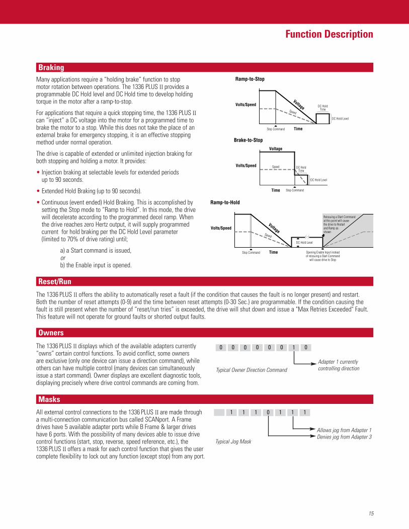
Many applications require a “holding brake” function to stop motor rotation between operations. The 1336 PLUS II provides aprogrammable DC Hold level and DC Hold time to develop holdingtorque in the motor after a ramp-to-stop.
For applications that require a quick stopping time, the 1336 PLUS IIcan “inject” a DC voltage into the motor for a programmed time tobrake the motor to a stop. While this does not take the place of anexternal brake for emergency stopping, it is an effective stoppingmethod under normal operation.
The drive is capable of extended or unlimited injection braking forboth stopping and holding a motor. It provides:
• Injection braking at selectable levels for extended periods up to 90 seconds.
• Extended Hold Braking (up to 90 seconds).
• Continuous (event ended) Hold Braking. This is accomplished bysetting the Stop mode to “Ramp to Hold”. In this mode, the drivewill decelerate according to the programmed decel ramp. Whenthe drive reaches zero Hertz output, it will supply programmedcurrent for hold braking per the DC Hold Level parameter(limited to 70% of drive rating) until;
a) a Start command is issued,orb) the Enable input is opened.
The 1336 PLUS II offers the ability to automatically reset a fault (if the condition that causes the fault is no longer present) and restart. Both the number of reset attempts (0-9) and the time between reset attempts (0-30 Sec.) are programmable. If the condition causing thefault is still present when the number of “reset/run tries” is exceeded, the drive will shut down and issue a "Max Retries Exceeded" Fault.This feature will not operate for ground faults or shorted output faults.
The 1336 PLUS II displays which of the available adapters currently “owns” certain control functions. To avoid conflict, some owners are exclusive (only one device can issue a direction command), whileothers can have multiple control (many devices can simultaneously issue a start command). Owner displays are excellent diagnostic tools, displaying precisely where drive control commands are coming from.
All external control connections to the 1336 PLUS II are made through a multi-connection communication bus called SCANport. A Frame drives have 5 available adapter ports while B Frame & larger drives have 6 ports. With the possibility of many devices able to issue drivecontrol functions (start, stop, reverse, speed reference, etc.), the 1336 PLUS II offers a mask for each control function that gives the user complete flexibility to lock out any function (except stop) from any port.
Volts/Speed
Ramp-to-Stop
TimeStop Command
egatloV
deepS
DC Hold Level
DC HoldTime
Brake-to-Stop
Volts/Speed
Voltage
Time Stop Command
Speed
DC Hold Level
DC HoldTime
Volts/Speed
Ramp-to-Hold
TimeStop Command
egatloV
deepS
DC Hold Level
Reissuing a Start Commandat this point will cause the drive to Restart and Ramp as shown
Opening Enable Input instead of reissuing a Start Command
will cause drive to Stop
Adapter 1 currentlycontrolling directionTypical Owner Direction Command
01000000
Allows jog from Adapter 1Denies jog from Adapter 3
Typical Jog Mask
1110111
Braking
Reset/Run
Owners
Masks
16
Function Description
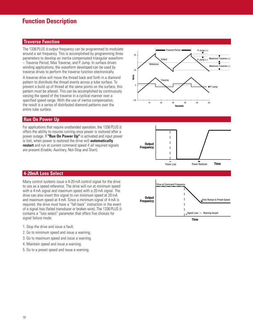
The 1336 PLUS II output frequency can be programmed to modulatearound a set frequency. This is accomplished by programming threeparameters to develop an inertia compensated triangular waveform– Traverse Period, Max Traverse, and P Jump. In surface drivenwinding applications, the waveform developed can be used bytraverse drives to perform the traverse function electronically.A traverse drive will move the thread back and forth in a diamondpattern to distribute the thread evenly across a tube surface. Toprevent a build up of thread at the same points on the surface, thispattern must be altered. This can be accomplished by continuouslyvarying the speed of the traverse in a cyclical manner over aspecified speed range. With the use of inertia compensation, the result is a series of distributed diamond patterns over the entire tube surface.
For applications that require unattended operation, the 1336 PLUS IIoffers the ability to resume running once power is restored after apower outage. If "Run On Power Up" is activated and input poweris lost, when power is restored the drive will automaticallyrestart and run at current command speed if all required signalsare present (Enable, Auxiliary, Not-Stop and Start).
Many control systems issue a 4-20 mA control signal for the driveto use as a speed reference. The drive will run at minimum speedwith a 4 mA signal and maximum speed with a 20 mA signal. Thedrive can also invert this signal to run minimum speed at 20 mAand maximum speed at 4 mA. Since a minimum signal of 4 mA isrequired, the drive must have a “fall back” instruction in the eventof a signal loss (failed transducer or broken wire). The 1336 PLUS IIcontains a “loss select” parameter that offers five choices forsignal failure mode.
1. Stop the drive and issue a fault.2. Go to minimum speed and issue a warning.3. Go to maximum speed and issue a warning.4. Maintain speed and issue a warning.5. Go to a preset speed and issue a warning.
Time
OutputFrequency
Power Lost Power Restored
OutputFrequency
Time
Signal Loss –– Warning Issued
Drive Ramps to Preset Speed
Drive at Command Frequency
Seconds
Hert
z
Maximum Traverse (–)
Traverse
P-Jump
P-Jump (+)
P-Jump (–)Output
Reference
Traverse Period
–20
0
10 20 30 40 50 60
20
40
Maximum Traverse (+)
Traverse Function
Run On Power Up
4-20mA Loss Select
17
Function Description
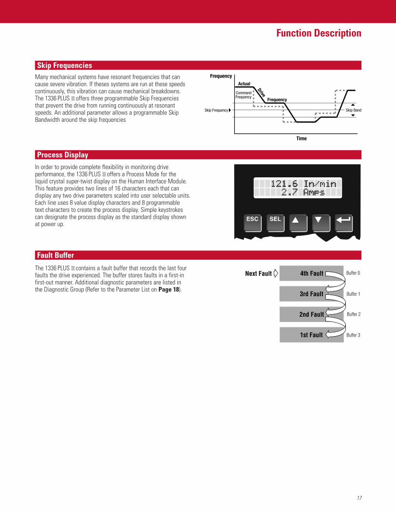
Many mechanical systems have resonant frequencies that cancause severe vibration. If theses systems are run at these speedscontinuously, this vibration can cause mechanical breakdowns.The 1336 PLUS II offers three programmable Skip Frequenciesthat prevent the drive from running continuously at resonantspeeds. An additional parameter allows a programmable SkipBandwidth around the skip frequencies
In order to provide complete flexibility in monitoring driveperformance, the 1336 PLUS II offers a Process Mode for the liquid crystal super-twist display on the Human Interface Module.This feature provides two lines of 16 characters each that candisplay any two drive parameters scaled into user selectable units.Each line uses 8 value display characters and 8 programmable text characters to create the process display. Simple keystrokescan designate the process display as the standard display shownat power up.
The 1336 PLUS II contains a fault buffer that records the last fourfaults the drive experienced. The buffer stores faults in a first-infirst-out manner. Additional diagnostic parameters are listed in the Diagnostic Group (Refer to the Parameter List on Page 18).
evirD
ycneuqerF
lautcA
Frequency
Time
Skip Frequency
CommandFrequency
Skip Band
3rd Fault Buffer 1
4th FaultNext Fault Buffer 0
2nd Fault Buffer 2
1st Fault Buffer 3
Skip Frequencies
Process Display
Fault Buffer
18
Parameter List
Group/Param. No. Disp. Units Min./Max. Values DefaultFrequency Setup (continued)
Pulse In Scale 264 Factor 1/4096 1024 PPREncoder PPR 46 Factor 1/4096 1024 PPRFeature Select
Dwell Frequency 43 0.1 Hertz 0.0/7.0 Hz 0.0 HzDwell Time 44 1 Second 0/10 Sec 0 SecSpeed Control 77 Settings Selection Parameter Slip CompSlip @ F.L.A. 42 0.1 Hertz 0.0/10.0 Hz 1.0 HzSlip Comp Gain 195 None 1/40 1 Run On Power Up 14 Settings Selection Parameter DisabledReset/Run Tries 85 1 Try 0/9 0 TriesReset/Run Time 15 0.1 Second 0.5/30.0 Sec 1.0 SecS Curve Enable 57 Settings Selection Parameter DisabledS Curve Time 56 0.1 Second 0.0/1800.0 Sec 0.0 SecLanguage 47 Settings Selection Parameter EnglishFlying Start En 155 Settings Selection Parameter DisabledFStart Forward 156 1 Hz 0/400 Hz 60 HzFStart Reverse 157 1 Hz 0/400 Hz 0 HzLLoss Restart 228 Settings Selection Parameter Track VoltsLLoss Mode 256 Settings Selection Parameter LoBus>OffLLoss Volts 320 1 Volt 40/80/100 Volts/200/400/500 Volts 59/117/146 VoltsLoss Recover 321 1 Volt 20/40/50 Volts/200/400/500 Volts 29/59/73 VoltsRide Thru Volts 322 1 Volt 40/80/100 Volts/200/400/500 Volts 29/59/73 VoltsMin Bus Volts 323 1 Volt 100/200/250 Volts/200/400/500 Volts 194/388/485 VoltsTraverse Inc 78 0.01 Sec 0.00/30.00 Sec 0.00 SecTraverse Dec 304 0.01 Sec 0.00/30.00 Sec 0.00 SecMax Traverse 79 0.01 Hz 0.00/50% [Maximum Freq] 0.00 HzP Jump 80 0.01 Hz 0.00/25% [Maximum Freq] 0.00 HzBus Regulation 288 Settings Selection Parameter DisabledLoad Loss Det 290 Settings Selection Parameter DisabledLoad Loss Level 291 1 % 0/100 % 0 %Load Loss Time 292 1 Second 0/30 Sec 0 SecBus Reg Level**/ 325 1 Volt 358/716/895 Volts 358/716/895 VoltsMax Bus Volts* 403/807/1009 VoltsDigital I/O
Input Mode 241 Mode # Selection Parameter StatusTB3 Term 22 242 Settings Selection Parameter Rev/For Input 3TB3 Term 23 243 Settings Selection Parameter Jog Input 4TB3 Term 24 244 Settings Selection Parameter Aux Fault Input 5TB3 Term 26 245 Settings Selection Parameter Spd Sel 3 Input 6TB3 Term 27 246 Settings Selection Parameter Spd Sel 2 Input 7TB3 Term 28 247 Settings Selection Parameter Spd Sel 1 Input 8Input Status 55 Settings Selection ParameterCR1 Out Select 158 Settings Selection Parameter At SpeedCR2 Out Select 174 Settings Selection Parameter RunningCR3 Out Select 175 Settings Selection Parameter FaultCR4 Out Select 176 Settings Selection Parameter AlarmDig Out Freq 159 0.01 Hz 0.00 Hz/ [Maximum Freq] 0.00 HzDig Out Current 160 0% 0/200% 0%Dig Out Torque 161 0.1A 0.0/200% of [Rated Amps] 0.0ADig At Temp 267 1° C 0/255° C 0PI Max Error 293 0.01 Hz ±400.00 Hz NonePulse Out Select 280 Settings Selection Parameter Output FreqPulse Out Scale 281 Factor 1/4096 1024 PPRPulse In Scale 264 Factor 1/4096 1024 PPRAt Time* 327 0.01 Sec 0.00/360.00 0.00 SecRemote CR Output* 326 Settings None xxxx0000Analog I/O
Anlg In 0 Lo 237 0.1 % ±300.0% 0.0%Anlg In 0 Hi 238 0.1 % ±300.0% 100.0%Anlg In 1 Lo 239 0.1% ±300.0% 0.0%Anlg In 1 Hi 240 0.1% ±300.0% 100.0%Anlg In 2 Lo 248 0.1% ±300.0% 0.0%Anlg In 2 Hi 249 0.1% ±300.0% 100.0%Analog Trim En 90 Settings Selection Parameter DisabledAnlg Signal Loss 250 Settings Selection Parameter Disabled4-20mA Loss Sel 150 Settings Selection Parameter Min/AlarmAnlg Out 0 Sel 25 Settings Selection Parameter FrequencyAnlg Out 0 Offset 154 Disabled Selection Parameter DisabledAnlg Out 0 Abs 233 Disabled Selection Parameter EnabledAnlg Out 0 Lo 234 0.1% ±300.0% 0.0%Anlg Out 0 Hi 235 0.1% ±300.0% 100.0%Anlg Out 1 Sel 274 Settings Selection Parameter CurrentAnlg Out 1 Abs 277 Enabled Selection Parameter EnabledAnlg Out 1 Offset 278 Enabled Selection Parameter DisabledAnlg Out 1 Lo 275 0.1% ±300.0% 0.0%Anlg Out 1 Hi 276 0.1% ±300.0% 100.0%Slot A Option 252 Settings Selection Parameter StandardSlot B Option 253 Settings Selection Parameter Standard*Firmware 3.001 & later**Firmware 4.001 & later***Firmware 5.001 & later
Group/Param. No. Disp. Units Min./Max. Values Default Metering
Output Current 54 0.1A 0/200% Rtd. Drv. Out. Current NoneOutput Voltage 1 1 Volt 0/200% Rtd. Drv. Out. Volts NoneOutput Power 23 1 kW ±200% Rtd. Drv. Out. Power NoneDC Bus Voltage 53 1 Volt 0/200% DC Bus Volt Max. NoneOutput Freq 66 0.01 Hertz ±400.00 Hz NoneFreq Command 65 0.01 Hertz ±400.00 Hz NoneAnlg In 0 Freq 138 0.01 Hertz 0.00/400.00 Hz NoneAnlg In 1 Freq 139 0.01 Hertz 0.00/400.00 Hz NoneAnlg In 2 Freq 140 0.01 Hertz 0.00/400.00 Hz NoneEncoder Freq 63 0.01 Hertz 0.00/400.00 Hz NonePulse Freq 254 0.01 Hertz 0.00/400.00 Hz NoneMOP Freq 137 0.01 Hertz 0.00/400.00 Hz NoneHeatsink Temp 70 1° C 0/255° C NonePower OL Count 84 1 % 0/200% NoneMotor OL Count 202 1 % 0/200% NoneLast Fault 4 Fault # None NoneTorque Current 162 0.1A ±200% Drive Rating NoneFlux Current 163 0.1A ±200% Drive Rating None% Output Power 3 1 % ±200% Drv. Rated Out. Power None% Output Curr 2 1 % 0/200% Rated Drv. Out. Curr. NoneElapsed Run Time 279 0.1 Hr 0/6553.5 0Setup
Input Mode 241 Mode # None StatusFreq Select 1 5 Settings Selection Parameter Adapter 1Accel Time 1 7 0.1 Second 0.0/3600.0 Sec 10.0 SecDecel Time 1 8 0.1 Second 0.0/3600.0 Sec 10.0 SecMinimum Freq 16 1 Hertz 0/120 Hz 0 HzMaximum Freq 19 1 Hertz 25/400 Hz 60 HzStop Select 1 10 Settings Selection Parameter CoastCurrent Limit 36 1% 20/300% (0.0/300.0***) Rated Amps150%Current Lmt Sel 232 Settings Selection Parameter Current LmtAdaptive I Lim 227 Settings Selection Parameter EnabledOverload Mode 37 Settings Selection Parameter No DerateOverload Amps 38 0.1A 20/115% Drive Rated Amps 115% Drv. Rtd.VT Scaling 203 Settings Selection Parameter DisabledMotor NP RPM 177 1 RPM 60/24000 RPM 1750 RPMMotor NP Hertz 178 1 Hertz 1/400 Hz 60 HzMotor NP Volts 190 1 Volt 0/2 x Drive Rated Volts Drv. Rated VoltsMotor NP Amps 191 1 Amp 0/2 x Drive Rated Amps Drv. Rated AmpsAdvanced Setup
Minimum Freq 16 1 Hertz 0/120 Hz 0 HzMaximum Freq 19 1 Hertz 25/400 Hz 60 HzPWM Frequency 45 2 kHz 2/8 kHz (A & B Frame) Based on Drv Type
2 kHz 2/6 kHz (C Frame & up) Based on Drv TypeAccel Time 2 30 0.1 Second 0.0/3600.0 Sec 10.0 SecDecel Time 2 31 0.1 Second 0.0/3600.0 Sec 10.0 SecSync Time 307 0.0 Second 0.0/6000.0 Sec 0.0 SecStop Select 1 10 Display Drive None CoastDC Hold Time 12 1 Second 0/90.0 Sec 0.0 SecDC Hold Level 13 1 % 0/150 % 100 %Hold Level Sel 231 Settings Selection Parameter DC Hold LvlBus Limit En 11 Settings Selection Parameter DisabledMotor Type 41 Settings Selection Parameter InductionStop Select 2 52 Settings Selection Parameter CoastKP Amps 193 NA 25/400 100Speed Brake En* 319 Settings Selection Parameter DisabledFrequency Setup
Freq Select 1 5 Settings Selection Parameter Adapter 1Freq Select 2 6 Settings Selection Parameter Preset 1Jog Frequency 24 0.1 Hertz 0.0/400.0 Hz 10.0 HzPreset Freq 1 27 0.1 Hertz 0.0/400.0 Hz 0.0 HzPreset Freq 2 28 0.1 Hertz 0.0/400.0 Hz 0.0 HzPreset Freq 3 29 0.1 Hertz 0.0/400.0 Hz 0.0 HzPreset Freq 4 73 0.1 Hertz 0.0/400.0 Hz 0.0 HzPreset Freq 5 74 0.1 Hertz 0.0/400.0 Hz 0.0 HzPreset Freq 6 75 0.1 Hertz 0.0/400.0 Hz 0.0 HzPreset Freq 7 76 0.1 Hertz 0.0/400.0 Hz 0.0 HzSkip Freq 1 32 1 Hertz 0/400 Hz 400 HzSkip Freq 2 33 1 Hertz 0/400 Hz 400 HzSkip Freq 3 34 1 Hertz 0/400 Hz 400 HzSkip Freq Band 35 1 Hertz 0/15 Hz 0 HzMOP Increment 22 0.1 Hertz/Sec 0/78% [Max. Freq]/Sec 1.1 Hz/SecSave MOP Ref 230 Settings Selection Parameter DisabledFreq Ref SqRoot 229 Settings Selection Parameter Disabled
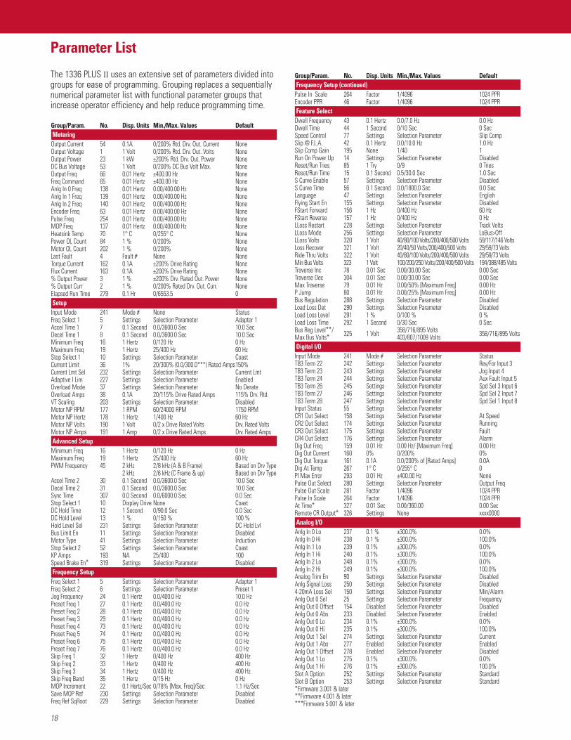
The 1336 PLUS II uses an extensive set of parameters divided intogroups for ease of programming. Grouping replaces a sequentiallynumerical parameter list with functional parameter groups thatincrease operator efficiency and help reduce programming time.
19
Parameter ListGroup/Param. No. Disp. Units Min./Max. Values Default FaultsFault Buffer 0 86 Fault Code Fault Storage NoneFault Buffer 1 87 Fault Code Fault Storage NoneFault Buffer 2 88 Fault Code Fault Storage NoneFault Buffer 3 89 Fault Code Fault Storage NoneClear Fault 51 Settings Selection Parameter ReadyCur Lim Trip En 82 Settings Selection Parameter DisabledShear Pin Fault 226 Settings Selection Parameter DisabledMotor OL Fault 201 Settings Selection Parameter EnabledMotor Therm Flt 268 Fault Code Fault Storage EnabledLine Loss Fault 40 Settings Selection Parameter DisabledBlwn Fuse Flt 81 Settings Selection Parameter EnabledLow Bus Fault 91 Settings Selection Parameter EnabledFault Data 207 Param. # 1/255 NoneFlt Motor Mode 143 Settings Read Only NoneFlt Power Mode 144 Settings Read Only NoneFault Frequency 145 0.01 Hertz 0.00/400.00 Hz NoneFault Status 1 146 Bit 1/0 Read Only NoneFault Status 2 286 Fault Code Fault Storage NoneFault Alarms 1 173 Bit 1/0 Read Only NoneFault Alarms 2 287 Fault Code Fault Storage NoneFlt Clear Mode 39 Settings Selection Parameter EnabledGround Warning 204 Settings Selection Parameter DisabledPhase Loss Mode* 330 Settings Selection Parameter DisabledPhase Loss Level* 331 0.1 Volts 5.1/10.1/12.7Volts/22.5/45.0/56.2 Volts 9.0/18.0/22.5 VoltsPrecharge Fault* 332 Settings Selection Parameter EnabledDiagnostics
Drive Status 1 59 Bit 1/0 Read Only NoneDrive Status 2 236 Bit 1/0 Read Only NoneApplication Sts 316 Bit 1/0 Read Only NoneDrive Alarm 1 60 Bit 1/0 Read Only NoneDrive Alarm 2 269 Bit 1/0 Read Only NoneLatched Alarms 1 205 Bit 1/0 Read Only NoneLatched Alarms 2 270 Bit 1/0 Read Only NoneInput Status 55 Bit 1/0 Read Only NoneFreq Source 62 Settings Read Only Use LastFreq Command 65 0.01 Hertz ±400.00 NoneDrive Direction 69 Settings Read Only NoneStop Mode Used 26 Settings Read Only CoastMotor Mode 141 Settings Read Only NonePower Mode 142 Settings Read Only NoneOutput Pulses 67 1 Pulse 0/65535 NoneCurrent Angle 72 1 Deg. Read Only NoneHeatsink Temp 70 1° C. 0/255° C NoneSet Defaults 64 Settings Selection Parameter ReadyDC Bus Memory 212 1 Volt Read Only NoneMeas. Volts 272 1 Volt Read Only NoneEEPROM Cksum 172 None Read Only NoneRatings
Rated Volts 147 1 Volt Read Only Drive RatingRated Amps 170 0.1 A Read Only Drive RatingRated kW 171 kW Read Only Drive RatingFirmware Ver. 71 None Read Only 0.00Cntrl Board Rev 251 None Read Only 0.00Rated CT Amps 148 0.1A Read Only Drive RatingRated CT kW 149 kW Read Only Drive RatingRated VT Amps 198 0.1A Read Only Drive RatingRated VT kW 199 kW Read Only Drive RatingDrive Type 61 Read Only Drive RatingMasks
Direction Mask 94 Bit 1/0 0/1 01111110Start Mask 95 Bit 1/0 0/1 01111111Jog Mask 96 Bit 1/0 0/1 01111111Reference Mask 97 Bit 1/0 0/1 01111111Accel Mask 98 Bit 1/0 0/1 01111111Decel Mask 99 Bit 1/0 0/1 01111111Fault Mask 100 Bit 1/0 0/1 01111111MOP Mask 101 Bit 1/0 0/1 01111111Traverse Mask 305 Bit 1/0 0/1 01111111Sync Mask 308 Bit 1/0 0/1 01111111Logic Mask 92 Bit 1/0 0/1 01111111Local Mask 93 Bit 1/0 0/1 01111111Alarm Mask 1 206 Bit 1/0 0/1 01111111Alarm Mask 2 271 Bit 1/0 0/1 01111111Owners
Stop Owner 102 Bit 1/0 Read Only NoneDirection Owner 103 Bit 1/0 Read Only NoneStart Owner 104 Bit 1/0 Read Only NoneJog Owner 105 Bit 1/0 Read Only NoneReference Owner 106 Bit 1/0 Read Only NoneAccel Owner 107 Bit 1/0 Read Only NoneDecel Owner 108 Bit 1/0 Read Only NoneFault Owner 109 Bit 1/0 Read Only None
Group/Param. No. Disp. Units Min./Max. Values Default Owners (continued)MOP Owner 110 Bit 1/0 Read Only NoneTraverse Owner 306 Bit 1/0 Read Only NoneSync Owner 309 Bit 1/0 Read Only NoneLocal Owner 179 Bit 1/0 Read Only NoneAdapter I/O
Data In (8) 111-118 Parameter # None 0Data Out (8) 119-126 Parameter # None 0Alt Type 2 Cmd 315 Settings Selection Parameter DisabledProcess Display
Process 1 Par 127 Parameter # None 1Process 1 Scale 128 Numeric ±327.67 +1.00Process 1 Txt 1-8 129-136 ASCII Code None VoltsProcess 2 Par 180 Parameter # None 54Process 2 Scale 181 Numeric ±327.67 +1.00Process 2 Txt 1-8 182-189 ASCII Code None AmpsEncoder Feedback
Speed Control 77 Settings Selection Parameter Slip CompEncoder Type 152 Settings Selection Parameter QuadratureEncoder PPR 46 Factor 1/4096 1024 PPRMaximum Speed 151 1 Hertz 0/400 Hz 400 HzMotor Poles 153 1 Pole Read Only NoneSpeed Kl 165 Numeric 0/20000 100Speed KP 164 Numeric 0/20000 0Speed Error 166 0.01 Hz ±8.33% [Base Frequency] NoneSpeed Integral 167 0.01 Hz ±8.33% [Base Frequency] NoneSpeed Adder 168 0.01 Hz ±8.33% [Base Frequency] NoneSlip Adder 255 0.01 Hz ±8.33% [Base Frequency] NoneMotor NP RPM 177 1 RPM 60/24000 RPM 1750 RPMMotor NP Hertz 178 1 Hertz 1/400 Hz 60 HzEncoder Counts 283 1 Count ±32767 0Enc Count Scale 282 0/4096 NoneEncoder Loss Sel 284 Settings Selection Parameter DisabledEncoder Freq 63 0.01 Hertz 0.00/400.00 Hz NoneMax Enc Counts* 328 1 Count 0/32767 0Process PI
Speed Control 77 Settings Selection Parameter Slip CompPI Config 213 Bit 1/0 0/1 00000000PI Status 214 Bit 1/0 Read Only NonePI Ref Select 215 Settings Selection Parameter Preset 1PI Fdbk Select 216 Settings Selection Parameter Analog In 1PI Reference 217 0.01 Hertz ±400.00 Hz NonePI Feedback 218 0.01 Hertz ±400.00 Hz NonePI Error 219 0.01 Hertz ±400.00 Hz NonePI Output 220 0.01 Hertz ±400.00 Hz NoneKI Process 221 N/A 0/1024 128KP Process 222 N/A 0/1024 256PI Neg Limit 223 0.01 Hz ±400.00 Hz –8.33% [Max Freq]PI Pos Limit 224 0.01 Hz ±400.00 Hz +8.33% [Max Freq]PI Preload 225 0.01 Hz ±8.33 [Max Freq] 0.00 HzMotor Control
Control Select 9 Settings Selection Parameter Sens VectorFlux Amps Ref 192 0.1A 0.0/75% Drive VT Rtd. Amps 0.0AIR Drop Volts 194 1 Volt 0/25% Drive Rated Voltage 0 VoltsFlux Up Time 200 0.1 Sec 0.0/5.0 Sec 0.0 SecStart Boost 48 1 Volt 0/9.5% Drive Rated Voltage 0 VoltsRun Boost 83 1 Volt 0/9.5% Drive Rated Voltage 0 VoltsBoost Slope 169 None 1.0/8.0 1.5Break Voltage 50 1 Volt 0/50% Drive Rated Voltage 25% Drive Rtd. VBreak Frequency 49 1 Hertz 0/120 Hz 25% [Max. Freq]Base Voltage 18 1 Volt 25/120% Drive Rated Voltage Drive Rtd. VoltsBase Frequency 17 1 Hertz 25/400 Hz 60 HzMaximum Voltage 20 1 Volt 25/120% Drive Rated Voltage Drive Rtd. VoltsRun/Accel Volts 317 1% 50%/100% 100%Sync Loss Sel 310 Settings Selection Parameter DisabledSync Loss Gain 311 Numeric 0/100 40Sync Loss Comp 313 1 Volt 0/25% of Drive Rtd. Volts 0 VoltsSync Loss Time 312 1 Sec 1/30 Sec 5 SecPWM Comp Time** 333 None 20/90 80Break Freq** 334 0.01 Hz 0/30 Hz 0 HzStep Logic
SLx Logic Step*** 335-371 Settings Selection Parameter Step On TimeSLx Logic Jump*** 336-372 Settings Selection Parameter Do Not StepSLx Step Jump*** 337-373 Settings Selection Parameter Jump to 0SLx Step Setting*** 338-374 Bit 1/0 0/1 xxxx0000SLx Time*** 339-375 0.01 Sec 0.00/600.00 0.00 SecSLx Encoder Cnts*** 340-376 1 Count ±32767 0Current Step 377 None 0/9 0
*Firmware 3.001 & later**Firmware 4.001 & later***Firmware 5.001 & later
20
Fault List
02 Auxiliary Fault The auxiliary input interlock is open03 Power Loss Fault DC bus voltage remained below 85% of nominal for longer than 500ms04 Undervolt Fault DC Bus voltage fell below the minimum value05 Overvolt Fault DC bus voltage exceeded maximum value06 Motor Stall Fault Current remained over 150% of [Rated Amps] for more than 4 seconds07 Overload Fault Internal electronic overload trip08 Overtemp Fault Heatsink temperature exceeds a predefined value of 90° C (195° F)09 Open Pot Fault An external pot is connected and the common side of the pot is open10 Serial Fault A SCANport adapter has been disconnected and the [Logic Mask] bit for that adapter is set to “1”11 Op Error Fault A SCANport device requests a Read or Write of data type not supported12 Overcurrent Flt Overcurrent is detected in instantaneous overcurrent trip circuit13 Ground Fault A current path to earth ground in excess of 100A has been detected at one or more of the drive output terminals14 Option Error An analog option board has been installed in the wrong slot15 Motor Thermistor An analog option board with thermistor input is installed and the value at the terminals is less than 60 ohms or greater than 3300 ohms16 Bipolar Dir Flt 3 Wire-Bipolar input is the active frequency reference and direction control is not possible
2 Wire-Run Forward or Run Reverse commands attempt direction control, but bipolar input is not masked from direction control19 Precharge Fault The precharge device was open 20ms after the end of a line loss condition or the bus charging alarm remains on for 20 seconds22 DSP Reset Fault Power-up has been attempted with an Open Stop contact or Closed Start contact23 Loop Overrn Fault An overrun of the 2.5ms control loop has occurred24 Motor Mode Fault A fault has been detected originating from the Control Board26 Power Mode Fault The internal power mode variable received an incorrect value29 Hertz Err Fault This fault indicates that there is not a valid operating frequency30 Hertz Sel Fault A frequency select parameter has been programmed with an out-of-range value32 EEPROM Fault EEPROM is being programmed and will not write a new value33 Max Retries Fault Drive unsuccessfully attempted to reset a fault and resume running for the programmed number of tries34 Prm Access Flt A communication error occurred between the microprocessor and serial EEPROM or DSP35 Neg Slope Fault Drive software detected a portion of the v/hz curve with a negative slope36 Diag C Lim Flt The [Cur Lim Trip En] parameter was enabled38 Phase U Fault A phase-to-ground fault has been detected between the drive and motor in this phase39 Phase V Fault A phase-to-ground fault has been detected between the drive and motor in this phase40 Phase W Fault A phase-to-ground fault has been detected between the drive and motor in this phase41 UV Short Fault Excessive current has been detected between these two output terminals42 UW Short Fault Excessive current has been detected between these two output terminals43 VW Short Fault Excessive current has been detected between these two output terminals47 Xsistr Desat Flt Output transistor(s) operating in the active region instead of desaturation. (Frame C & Above)48 Reprogram Fault The drive was commanded to write default values to EEPROM49 Input Phase Flt The drive is operated on single phase power50 Poles Calc Fault Generated if the calculated value of [Motor Poles] is less than 2 or greater than 3251 Bgnd 10ms Over Microprocessor loop fault52 Fgnd 10ms Over Microprocessor loop fault53 EE Init Read Trouble reading EEPROM during initialization or gate drive board needs replacing54 EE Init Value Stored parameter value out of range on initialization55 Temp Sense Open Heatsink thermistor is open or malfunctioning56 Precharge Open The precharge circuit was commanded to close, but was detected to be open57 Ground Warning A current path to earth ground in excess of 2A has been detected at one or more of the drive output terminals58 Blwn Fuse Flt The bus fuse in 30kW (40 HP) and up drives has blown61 Mult Prog Input A single source input function has been programmed to more than one input or more than one “Run Reverse” input62 Ill Prog Input [Fault Data] = 98: “3 Wire” is selected as the [Input Mode] and one or more digital inputs are programmed to “Run Reverse”63 Shear Pin Fault Programmed [Current Limit] amps has been exceeded64 Power Overload The drive rating of 150% for 1 minute has been exceeded65 Adptr Freq Err The SCANport adapter sent an illegal frequency reference to the drive66 EEPROM Checksum The checksum read from the EEPROM does not match the checksum calculated from the EEPROM data68 ROM or RAM Fit Internal power-up ROM or RAM tests have not executed properly69 Step Logic Flt [SLx Step Jump] is set to “End Fault” or [Encoder Counts] has reached the endpoint of ±32767
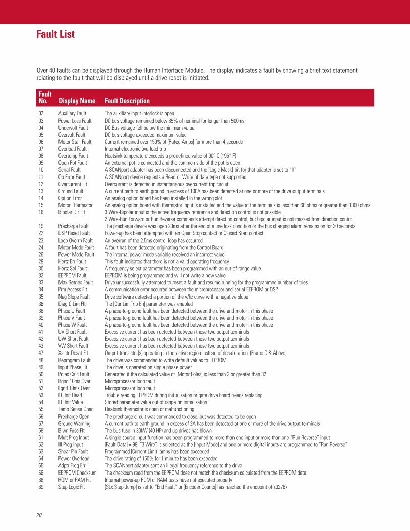
Over 40 faults can be displayed through the Human Interface Module. The display indicates a fault by showing a brief text statementrelating to the fault that will be displayed until a drive reset is initiated.
Fault No. Display Name Fault Description
21
Pre-Installation
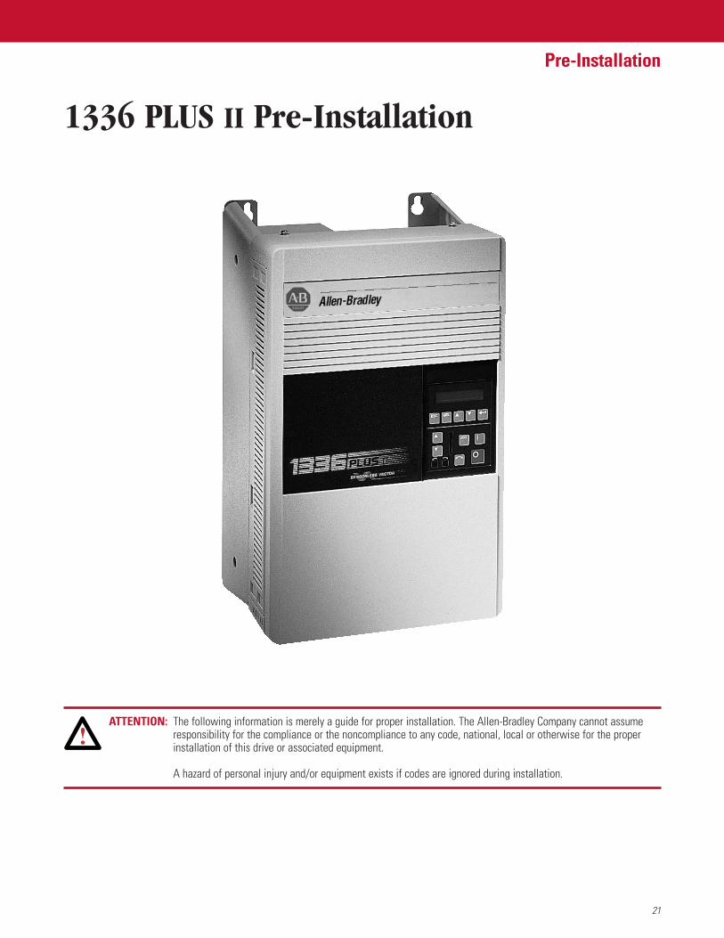
1336 PLUS II Pre-Installation
ATTENTION: The following information is merely a guide for proper installation. The Allen-Bradley Company cannot assumeresponsibility for the compliance or the noncompliance to any code, national, local or otherwise for the properinstallation of this drive or associated equipment.
A hazard of personal injury and/or equipment exists if codes are ignored during installation.
22
Pre-Installation
Features
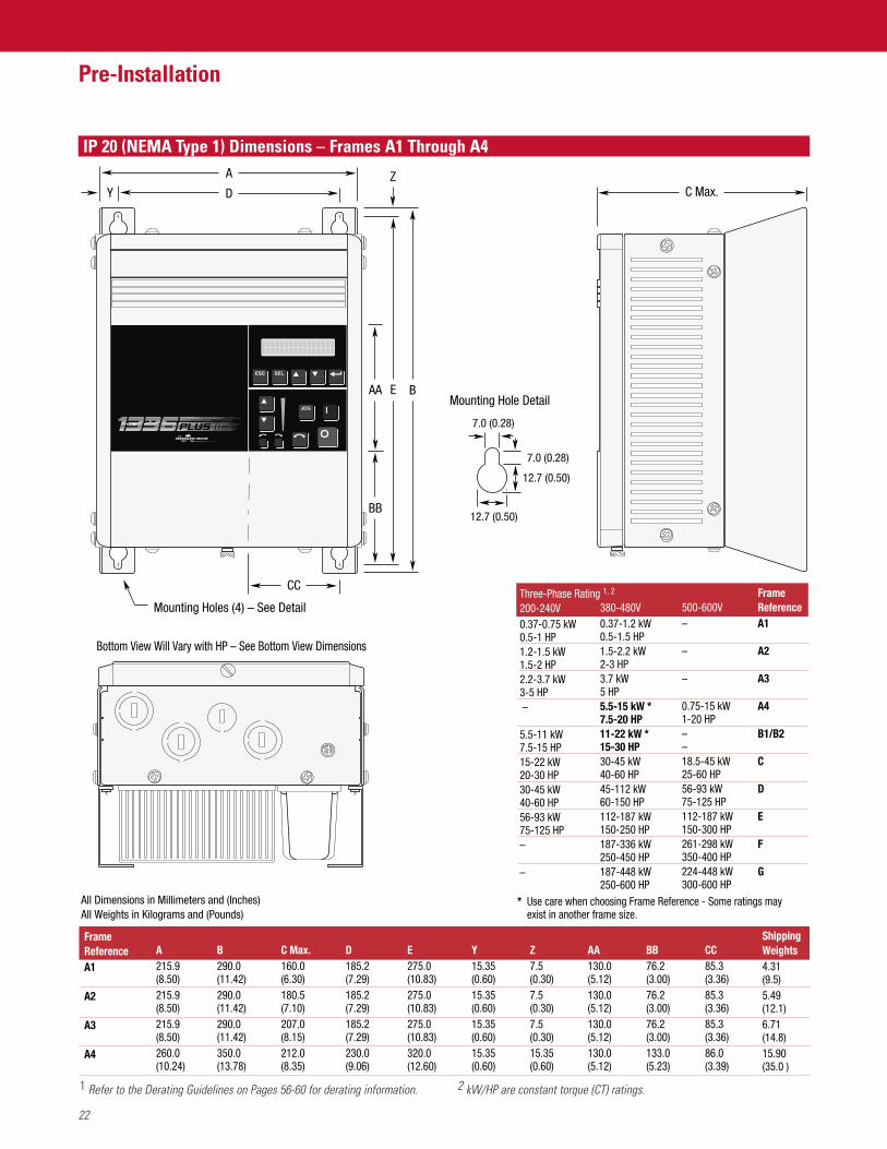
1 Refer to the Derating Guidelines on Pages 56-60 for derating information. 2 kW/HP are constant torque (CT) ratings.
All Dimensions in Millimeters and (Inches)All Weights in Kilograms and (Pounds)
C Max.D
A
Y
CC
E B
Z
BB
AA
A215.9(8.50)215.9(8.50)215.9(8.50)260.0(10.24)
B290.0(11.42)290.0(11.42)290.0(11.42)350.0(13.78)
C Max.160.0(6.30)180.5(7.10)207.0(8.15)212.0(8.35)
D185.2(7.29)185.2(7.29)185.2(7.29)230.0(9.06)
E275.0(10.83)275.0(10.83)275.0(10.83)320.0(12.60)
Y15.35(0.60)15.35(0.60)15.35(0.60)15.35(0.60)
Z7.5(0.30)7.5(0.30)7.5(0.30)15.35(0.60)
AA130.0(5.12)130.0(5.12)130.0(5.12)130.0(5.12)
BB76.2(3.00)76.2(3.00)76.2(3.00)133.0(5.23)
CC85.3(3.36)85.3(3.36)85.3(3.36)86.0(3.39)
ShippingWeights4.31 (9.5)5.49(12.1)6.71(14.8)15.90(35.0 )
Mounting Holes (4) – See Detail
7.0 (0.28)
7.0 (0.28)
12.7 (0.50)
12.7 (0.50)
Mounting Hole Detail
Three-Phase Rating 1, 2
200-240V0.37-0.75 kW0.5-1 HP1.2-1.5 kW1.5-2 HP2.2-3.7 kW3-5 HP – 5.5-11 kW7.5-15 HP15-22 kW20-30 HP30-45 kW40-60 HP56-93 kW75-125 HP– –
380-480V0.37-1.2 kW0.5-1.5 HP1.5-2.2 kW2-3 HP3.7 kW5 HP5.5-15 kW *7.5-20 HP11-22 kW *15-30 HP30-45 kW40-60 HP45-112 kW60-150 HP112-187 kW150-250 HP187-336 kW250-450 HP187-448 kW250-600 HP
500-600V–
–
–
0.75-15 kW1-20 HP––18.5-45 kW25-60 HP56-93 kW75-125 HP112-187 kW150-300 HP261-298 kW350-400 HP 224-448 kW300-600 HP
FrameReferenceA1
A2
A3
A4
B1/B2
C
D
E
F
G
Frame ReferenceA1
A2
A3
A4
Bottom View Will Vary with HP – See Bottom View Dimensions
Use care when choosing Frame Reference - Some ratings mayexist in another frame size.
*
IP 20 (NEMA Type 1) Dimensions – Frames A1 Through A4
23
Pre-Installation
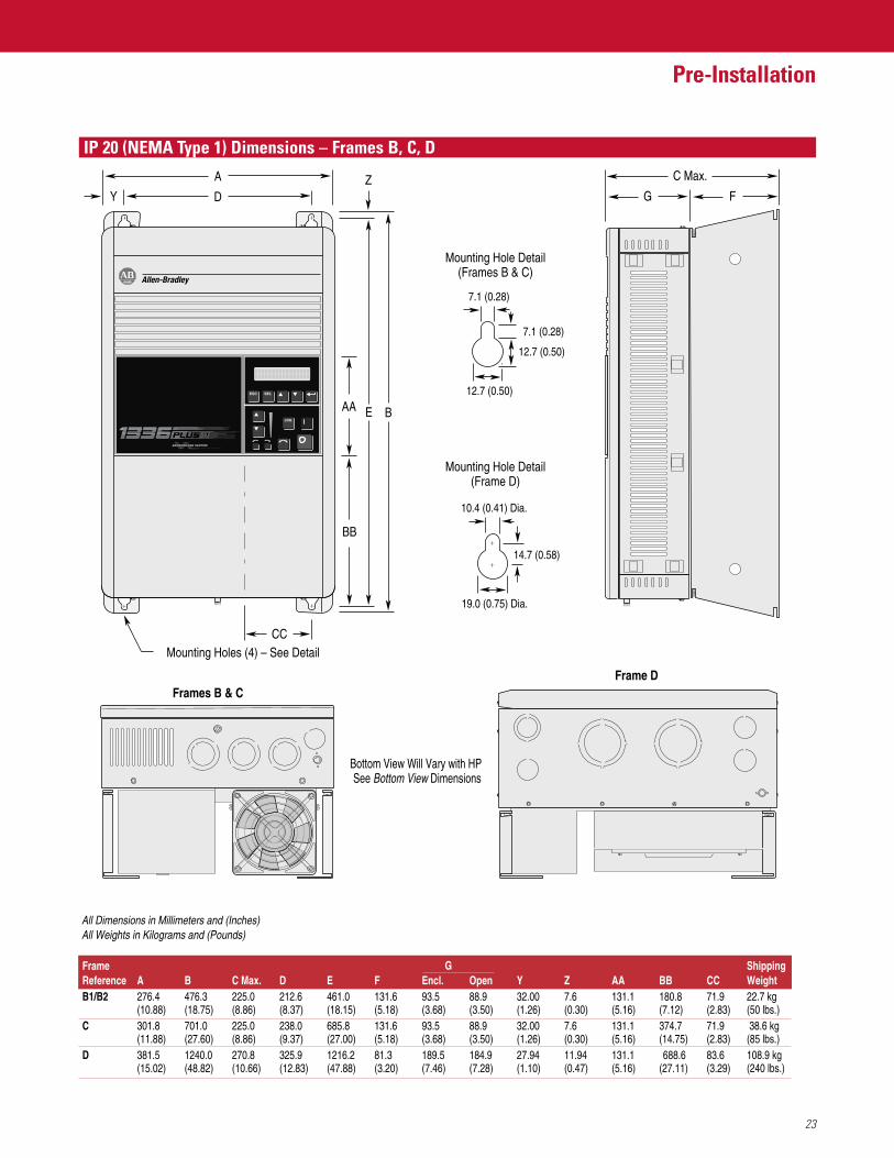
IP 20 (NEMA Type 1) Dimensions – Frames B, C, D
Bottom View Will Vary with HP See Bottom View Dimensions
FG
C Max.
All Dimensions in Millimeters and (Inches)All Weights in Kilograms and (Pounds)
D
A
Y
CC
E B
Z
BB
AA
7.1 (0.28)
7.1 (0.28)
12.7 (0.50)
12.7 (0.50)
10.4 (0.41) Dia.
19.0 (0.75) Dia.
14.7 (0.58)
Mounting Hole Detail(Frames B & C)
Mounting Hole Detail(Frame D)
Mounting Holes (4) – See Detail
ShippingWeight22.7 kg(50 lbs.) 38.6 kg(85 lbs.)108.9 kg(240 lbs.)
CC71.9(2.83)71.9(2.83)83.6(3.29)
FrameReferenceB1/B2
C
D
A276.4(10.88)301.8(11.88)381.5(15.02)
B476.3(18.75)701.0(27.60)1240.0(48.82)
C Max.225.0(8.86)225.0(8.86)270.8(10.66)
D212.6(8.37)238.0(9.37)325.9(12.83)
E461.0(18.15)685.8(27.00)1216.2(47.88)
F131.6(5.18)131.6(5.18)81.3(3.20)
Encl.93.5(3.68)93.5(3.68)189.5(7.46)
Open88.9(3.50)88.9(3.50)184.9(7.28)
Y32.00(1.26)32.00(1.26)27.94(1.10)
Z7.6(0.30)7.6(0.30)11.94(0.47)
AA131.1(5.16)131.1(5.16)131.1(5.16)
BB180.8(7.12)374.7(14.75) 688.6(27.11)
G
Frame DFrames B & C
24
Pre-Installation
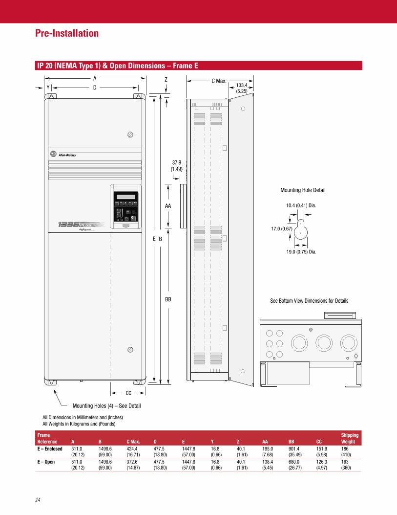
IP 20 (NEMA Type 1) & Open Dimensions – Frame E
C Max.
All Dimensions in Millimeters and (Inches)All Weights in Kilograms and (Pounds)
D
A
Y
CC
E B
Z
BB
AA
Mounting Holes (4) – See Detail
ShippingWeight186(410)163(360)
CC151.9(5.98)126.3(4.97)
Frame ReferenceE – Enclosed
E – Open
A511.0(20.12)511.0(20.12)
B1498.6(59.00)1498.6(59.00)
C Max.424.4(16.71)372.6(14.67)
D477.5(18.80)477.5(18.80)
E1447.8(57.00)1447.8(57.00)
Y16.8(0.66)16.8(0.66)
Z40.1(1.61)40.1(1.61)
AA195.0(7.68)138.4(5.45)
BB901.4(35.49)680.0(26.77)
37.9(1.49)
Mounting Hole Detail
See Bottom View Dimensions for Details
10.4 (0.41) Dia.
133.4(5.25)
17.0 (0.67)
19.0 (0.75) Dia.
Pre-Installation
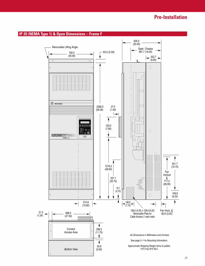
IP 20 (NEMA Type 1) & Open Dimensions – Frame F
2286.0(90.00)
762.0(30.00) 252.7
(9.95)
635.0(25.00)
Open Chassis487.7 (19.20)
37.9(1.49)
274.8(10.82)
193.0(7.60)
1219.2(48.00)
527.1(20.75)
All Dimensions in Millimeters and (Inches)
ConduitAccess Area
Bottom View
31.5(1.24)
698.5(27.50)
298.5(11.75)
50.8(2.00)
See page 2–1 for Mounting Information.
Approximate Shipping Weight (drive & pallet):415.0 kg (915 lbs.)
Removable Lifting Angle
63.5 (2.50)
196.9(7.75)
108.0 (4.25) x 158.8 (6.25)Removable Plate for
Cable Access (1 each side)
19.1(0.75)
FanVertical
CL711.2
(28.00)
Fan Horiz. CL 82.6 (3.25)
501.7(19.75)
158.8(6.25)
25
26
Pre-Installation
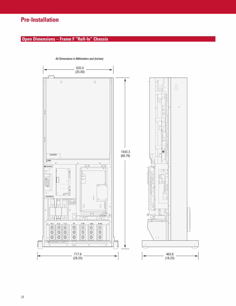
Open Dimensions – Frame F “Roll-In” Chassis
DANGER
DANGER
DANGER
DANGER
DANGER
DANGER
T-L3R-L1 S-L2 W-M3
TE
U-M1PE V-M2
717.6(28.25)
463.6(18.25)
635.0(25.00)
1543.3(60.76)
All Dimensions in Millimeters and (Inches)
27
Pre-Installation
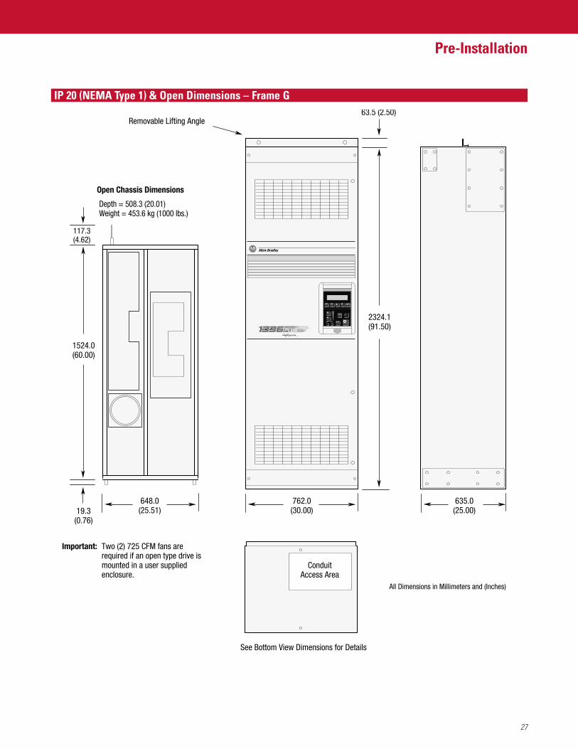
IP 20 (NEMA Type 1) & Open Dimensions – Frame G
2324.1(91.50)
Removable Lifting Angle
762.0(30.00)
Open Chassis Dimensions
635.0(25.00)
63.5 (2.50)
ConduitAccess Area
See Bottom View Dimensions for Details
648.0(25.51)19.3
(0.76)
1524.0(60.00)
117.3(4.62)
Depth = 508.3 (20.01)Weight = 453.6 kg (1000 lbs.)
All Dimensions in Millimeters and (Inches)
Important: Two (2) 725 CFM fans are required if an open type drive is mounted in a user supplied enclosure.
28
Pre-Installation
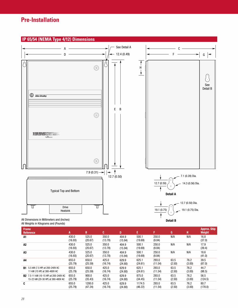
IP 65/54 (NEMA Type 4/12) Dimensions
Typical Top and BottomDetail A
See Detail A
SeeDetail B
A
D F G
H
C
E B
12.7 (0.50)
12.4 (0.49)
7.9 (0.31)
Frame ReferenceA1
A2
A3
A4
B1
B2
C
A430.0(16.93)430.0(16.93)430.0(16.93)655.0(25.79)655.0(25.79)655.0(25.79)655.0(25.79)
B525.0(20.67)525.0(20.67)525.0(20.67)650.0(25.59)650.0(25.59)900.0(35.43)1200.0(47.24)
C350.0(13.78)350.0(13.78)350.0(13.78)425.0(16.74)425.0(16.74)425.0(16.74)425.0(16.74)
E500.1(19.69)500.1(19.69)500.1(19.69)625.1(24.61)625.1(24.61)875.0(34.45)1174.5(46.22)
D404.9(15.94)404.9(15.94)404.9(15.94)629.9(24.80)629.9(24.80)629.9(24.80)629.9(24.80)
F250.0(9.84)250.0(9.84)250.0(9.84)293.0(11.54)293.0(11.54)293.0(11.54)293.0(11.54)
GN/A
N/A
N/A
63.5(2.50)63.5(2.50)63.5(2.50)63.5(2.50)
HN/A
N/A
N/A
76.2(3.00)76.2(3.00)76.2(3.00)76.2(3.00)
All Dimensions in Millimeters and (Inches)All Weights in Kilograms and (Pounds)
7.1 (0.28) Dia.
12.7 (0.50)
12.7 (0.50) Dia.
14.3 (0.56) Dia.
DriveHeatsink
Detail B
19.1 (0.75) 19.1 (0.75) Dia.
5.5 kW (7.5 HP) at 200-240V AC11 kW (15 HP) at 380-480V AC
7.5-11 kW (10-15 HP) at 200-240V AC15-22 kW (20-30 HP) at 380-480V AC
Approx. ShipWeight 16.8(37.0)17.9(39.4)18.6(41.0)39.5(87.0)44.7(98.5)56.5(124.5)80.7(178.0)
29
Pre-Installation
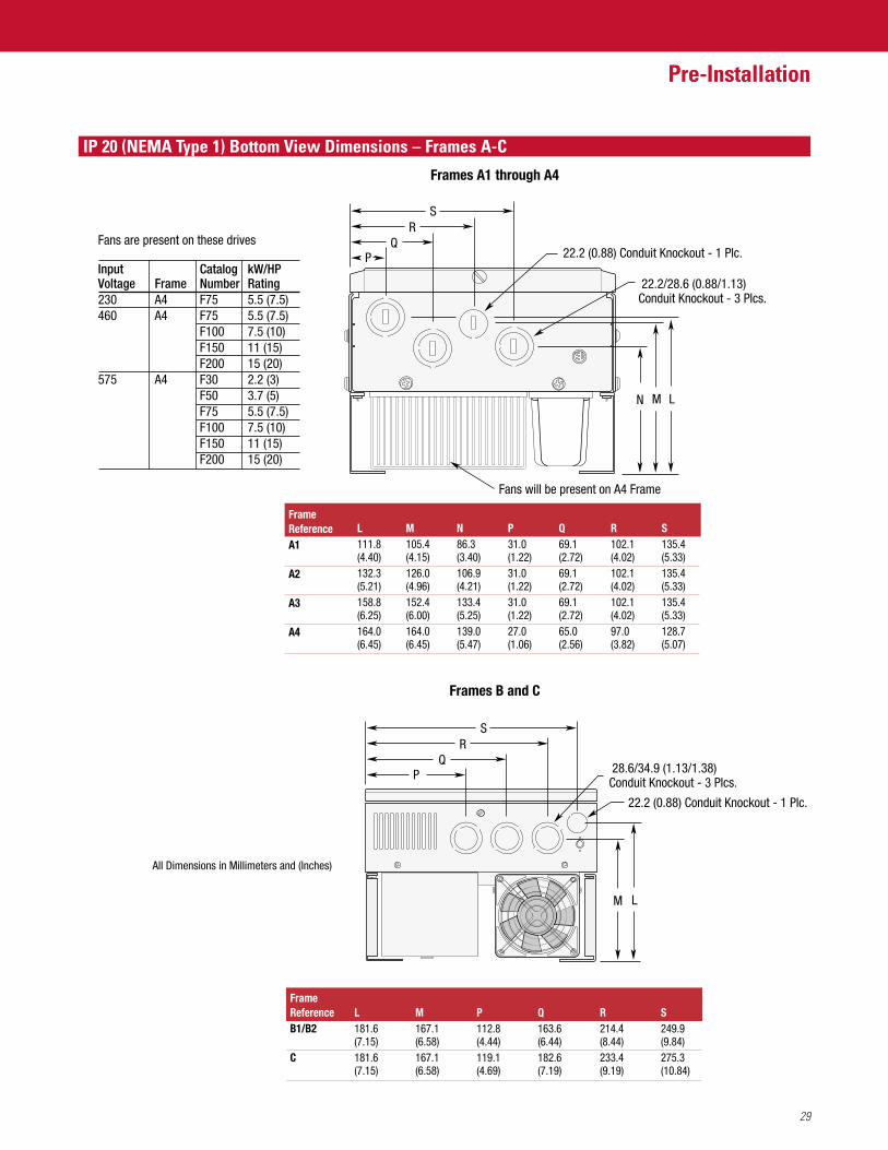
IP 20 (NEMA Type 1) Bottom View Dimensions – Frames A-C
All Dimensions in Millimeters and (Inches)
Frames B and C
Frames A1 through A4
LM
FrameReferenceB1/B2
C
L181.6(7.15)181.6(7.15)
M167.1(6.58)167.1(6.58)
P112.8(4.44)119.1(4.69)
Q163.6(6.44)182.6(7.19)
R214.4(8.44)233.4(9.19)
S249.9(9.84)275.3(10.84)
FrameReferenceA1
A2
A3
A4
L111.8(4.40)132.3(5.21)158.8(6.25)164.0(6.45)
M105.4(4.15)126.0(4.96)152.4(6.00)164.0(6.45)
N86.3(3.40)106.9(4.21)133.4(5.25)139.0(5.47)
P31.0(1.22)31.0(1.22)31.0(1.22)27.0(1.06)
Q69.1(2.72)69.1(2.72)69.1(2.72)65.0(2.56)
R102.1(4.02)102.1(4.02)102.1(4.02)97.0(3.82)
S135.4(5.33)135.4(5.33)135.4(5.33)128.7(5.07)
QR
P
S
28.6/34.9 (1.13/1.38)Conduit Knockout - 3 Plcs.
22.2 (0.88) Conduit Knockout - 1 Plc.
MN L
QR
P
S
22.2/28.6 (0.88/1.13)Conduit Knockout - 3 Plcs.
22.2 (0.88) Conduit Knockout - 1 Plc.
Fans will be present on A4 Frame
Fans are present on these drives
Input Catalog kW/HPVoltage Frame Number Rating230 A4 F75 5.5 (7.5)460 A4 F75 5.5 (7.5)
F100 7.5 (10)F150 11 (15)F200 15 (20)
575 A4 F30 2.2 (3)F50 3.7 (5)F75 5.5 (7.5)F100 7.5 (10)F150 11 (15)F200 15 (20)
30
Pre-Installation
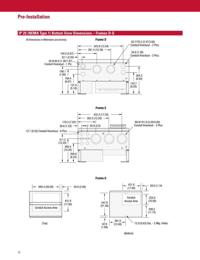
IP 20 (NEMA Type 1) Bottom View Dimensions – Frames D-G
305.3 (12.02)178.3 (7.02)
50.8 (2.0)38.6 (1.52)
432.3 (17.02)
88.9/101.6 (3.50/4.00)Conduit Knockout - 3 Plcs.
12.7 (0.50) Conduit Knockout - 6 Plcs.
All Dimensions in Millimeters and (Inches)
209.6(8.25)
Frame E
Frame G
Frame D
343.9 (13.54)261.4 (10.29)
131.6(5.18)
198.1(7.80)
52.1 (2.05)144.0 (5.67)
169.4(6.67)
204.5(8.05)
153.7(6.05)
311.2(12.25)
260.4(10.25)
34.9 (1.38)Conduit Knockout - 3 Plcs.
34.9/50.0 (1.38/1.97)Conduit Knockout - 1 Plc.
62.7/76.2 (2.47/3.00)Conduit Knockout - 2 Plcs.
(Bottom)
(Top)
29.0 (1.14)
15.9 (0.63) Dia. - 2 Mtg. Holes
431.8(17.00)
381.0(15.00)
298.5(11.75)
42.9(1.69)
254.0(10.00)
547.6(21.56)
ConduitAccess Area
Conduit Access Area
660.4 (26.00) 50.8 (2.00)
431.8(17.00)

31
Pre-Installation
Mounting Requirements
Input Power Conditioning
JOG
ESC SEL
101.6 mm(4.0 in.)
JOG
ESC SEL
152.4 mm(6.0 in.)
152.4 mm(6.0 in.)
152.4 mm(6.0 in.)
152.4 mm(6.0 in.)
UP
NOTE: F Frame drives require 152.4 mm (6.0 in.) on the sides and/or back for proper air flow.
In general, the 1336 PLUS II is suitable for direct connection to a correct voltage AC line that has a minimum impedance of 1% (3% for0.37-22 kW/0.5-30 HP drives) relative to the rated drive input kVA. If the line has a lower impedance, a line reactor or isolation transformermust be added before the drive to increase line impedance. If the line impedance is too low, transient voltage spikes or interruptions can create excessive current spikes that will cause nuisance input fuse blowing, overvoltage faults and may cause damage to the drive power structure.The basic rules for determining if a line reactor or isolation transformer is required are as follows:
1. If the AC input power system does not have a neutral or one phase referenced to ground (see Unbalanced Distribution Systems onnext page), an isolation transformer with the neutral of the secondary grounded is highly recommended. If the line-to-groundvoltages on any phase can exceed 125% of the nominal line-to-line voltage, an isolation transformer with the neutral of thesecondary grounded, is highly recommended.
2. If the AC line supplying the drive has power factor correction capacitors that are switched in and out, an isolation transformer or 5% reactors are recommended between the drive and capacitors. If the capacitors are permanently connected and not switched, the general rules for impedance mismatch (see above) apply.
3. If the AC line frequently experiences transient power interruptions or significant voltage spikes, an isolation transformer or 5% reactors are recommended.
Refer to Unbalanced Distribution Systems on next page.
32
Pre-Installation
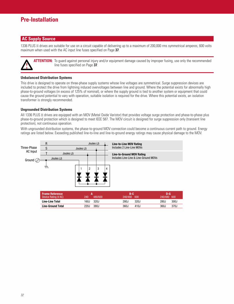
AC Supply Source1336 PLUS II drives are suitable for use on a circuit capable of delivering up to a maximum of 200,000 rms symmetrical amperes, 600 voltsmaximum when used with the AC input line fuses specified on Page 37.
ATTENTION: To guard against personal injury and/or equipment damage caused by improper fusing, use only the recommendedline fuses specified on Page 37.
Unbalanced Distribution SystemsThis drive is designed to operate on three-phase supply systems whose line voltages are symmetrical. Surge suppression devices areincluded to protect the drive from lightning induced overvoltages between line and ground. Where the potential exists for abnormally highphase-to-ground voltages (in excess of 125% of nominal), or where the supply ground is tied to another system or equipment that couldcause the ground potential to vary with operation, suitable isolation is required for the drive. Where this potential exists, an isolationtransformer is strongly recommended.
Ungrounded Distribution SystemsAll 1336 PLUS II drives are equipped with an MOV (Metal Oxide Varistor) that provides voltage surge protection and phase-to-phase plusphase-to-ground protection which is designed to meet IEEE 587. The MOV circuit is designed for surge suppression only (transient lineprotection), not continuous operation.With ungrounded distribution systems, the phase-to-ground MOV connection could become a continuous current path to ground. Energyratings are listed below. Exceeding published line-to-line and line-to-ground energy ratings may cause physical damage to the MOV.
1 2 3 4
Joules (J)Ground
Three-PhaseAC Input
T
SR
Joules (J)
Joules (J)
Joules (J)
Frame ReferenceDevice Rating (V AC)
Line-Line Total
Line-Ground Total
B-C240/480 600
280J 320J
360J 410J
A 240 480/600
160J 320J
220J 380J
D-G 240/480 600
280J 300J
360J 370J
Line-to-Line MOV RatingIncludes 2 Line-Line MOVs
Line-to-Ground MOV RatingIncludes Line-Line & Line-Ground MOVs
33
Pre-Installation
Input Fuses and Circuit Breakers
IEC Installations
1336 PLUS II can be installed with either input fuses or an input circuit breaker. Local/national electrical codes may determine additionalrequirements for these installations.
FusesIn general, the specified fuses are sutiable for branch short circuit protection and provide excellent short circuit protection for the drive. Thefuses offer a high interrupting capacity and are fast acting. Refer to the North American selections in the table on page 37.Circuit BreakersThe Westinghouse HMCP breakers specified in the table on pages 34-35 also provide branch short circuit protection. Because circuitbreakers are typically slower than fuses and those listed are magnetic trip only, they may not be as effective in offering short circuitprotection to the drive in the event of an internal drive short circuit. They may not be as effective in limiting damage to the drive.
FusesFor those installations that are not required to meet the U.S. NEC/UL/CSA, the specified fuses are sutiable for branch short circuitprotection and provide excellent short circuit protection for the drive. The fuses offer a high interrupting capacity and are fast acting. Refer to the European selections in the table on page 37.Circuit BreakersFor those installations that are not required to meet the U.S. NEC/UL/CSA requirements, additional devices are available as input circuit breakers. The Bulletin 140 and KTA3 devices meet the circuit breaker requirements of IEC947-2, but do not meet UL/CSA circuitbreaker requirements. They can be used in “non-U.S.” installations where local/national codes allow, if they are installed per theirinstallation instructions.
ATTENTION: The 1336 PLUS II does not provide input power short circuit protection. Specifications for the recommended fuse orcircuit breaker to provide drive input power protection against short circuits are provided.
Installations Per U.S. NEC/UL/CSA
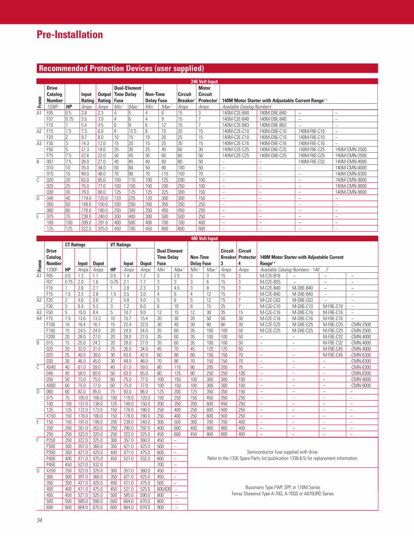
Recommended Protection Devices (user supplied)
34
Pre-Installation
Drive Dual-Element MotorCatalog Input Output Time Delay Non-Time Circuit Circuit Number Rating Rating Fuse Delay Fuse Breaker3 Protector4 140M Motor Starter with Adjustable Current Range5, 6
1336F- HP Amps Amps Min.1 Max.2 Min.1 Max.2 Amps Amps Available Catalog Numbers7
A1 F05 0.5 2.8 2.3 4 5 4 6 15 3 140M-C2E-B40 140M-D8E-B40 – –F07 0.75 3.5 3.0 4 6 4 9 15 7 140M-C2E-B40 140M-D8E-B40 – –F10 1 5.4 4.5 6 9 6 12 15 7 140M-C2E-B63 140M-D8E-B63 – –
A2 F15 1.5 7.3 6.0 8 12.5 8 15 20 15 140M-C2E-C10 140M-D8E-C10 140M-F8E-C10 –F20 2 9.7 8.0 10 15 10 20 25 15 140M-C2E-C10 140M-D8E-C10 140M-F8E-C10 –
A3 F30 3 14.3 12.0 15 20 15 25 35 15 140M-C2E-C16 140M-D8E-C16 140M-F8E-C16 –F50 5 21.3 18.0 25 30 25 45 60 30 140M-C2E-C25 140M-D8E-C25 140M-F8E-C25 140M-CMN-2500F75 7.5 22.6 22.0 30 45 30 60 80 50 140M-C2E-C25 140M-D8E-C25 140M-F8E-C25 140M-CMN-2500
B 007 7.5 28.0 27.0 40 45 40 60 80 50 – – 140M-F8E-C32 140M-CMN-4000010 10 35.0 34.0 50 60 50 80 100 50 – – – 140M-CMN-4000015 15 49.0 48.0 70 90 70 110 150 70 – – – 140M-CMN-6300
C 020 20 63.0 65.0 100 110 100 125 200 100 – – – 140M-CMN-9000025 25 75.0 77.0 100 150 100 200 250 100 – – – 140M-CMN-9000030 30 79.0 80.0 125 175 125 225 300 150 – – – 140M-CMN-9000
D 040 40 119.0 120.0 120 225 120 300 300 150 – – – –050 50 149.0 150.0 200 250 200 350 350 250 – – – –060 60 178.0 180.0 250 300 250 450 450 250 – – – –
E 075 75 238.0 240.0 300 400 300 500 500 250 – – – –100 100 289.0 291.0 400 500 400 700 700 400 – – – –125 125 322.0 325.0 450 700 450 800 800 600 – – – –
240 Volt Input
CT Ratings VT RatingsDrive Dual Element Circuit CircuitCatalog Time Delay Non-Time Breaker Protector 140M Motor Starter with Adjustable CurrentNumber Input Ouput Input Ouput Fuse Delay Fuse 3 4 Range5, 6
1336F- HP Amps Amps HP Amps Amps Min.1 Max.2 Min.1 Max.2 Amps Amps Available Catalog Numbers - 140 . . .7A1 F05 0.5 1.3 1.1 0.5 1.4 1.2 3 2.5 3 3 15 3 M-C2E-B16 – – –
F07 0.75 2.0 1.6 0.75 2.1 1.7 3 3 3 6 15 3 M-C2E-B25 – – –F10 1 2.6 2.1 1 2.8 2.3 3 4.5 3 8 15 3 M-C2E-B40 M-D8E-B40 – –F15 1.5 3.3 2.8 1.5 3.5 3.0 4 6 4 12 15 7 M-C2E-B40 M-D8E-B40 – –
A2 F20 2 4.6 3.8 2 4.8 4.0 5 6 5 12 15 7 M-C2E-C63 M-D8E-C63 – –F30 3 6.4 5.3 3 7.2 6.0 8 10 8 15 25 7 M-C2E-C10 M-D8E-C10 M-F8E-C10 –
A3 F50 5 10.0 8.4 5 10.7 9.0 12 15 12 30 35 15 M-C2E-C16 M-D8E-C16 M-F8E-C16 –A4 F75 7.5 13.6 13.3 10 15.7 15.4 20 30 20 50 50 30 M-C2E-C16 M-D8E-C16 M-F8E-C16 –
F100 10 16.4 16.1 15 22.4 22.0 30 40 30 80 80 30 M-C2E-C25 M-D8E-C25 M-F8E-C25 -CMN-2500F150 15 24.5 24.0 20 24.5 24.0 35 60 35 100 100 50 M-C2E-C25 M-D8E-C25 M-F8E-C25 -CMN-2500F200 20 28.0 27.0 20 28.0 27.0 35 60 35 100 100 50 – – M-F8E-C32 -CMN-4000
B 015 15 25.0 24.2 20 28.0 27.0 35 60 35 100 100 50 – – M-F8E-C32 -CMN-4000020 20 32.0 31.0 25 35.0 34.0 45 70 45 125 125 50 – – M-F8E-C45 -CMN-4000025 25 40.0 39.0 30 43.0 42.0 60 90 60 150 150 70 – – M-F8E-C45 -CMN-6300030 30 46.0 45.0 30 49.0 48.0 70 90 70 150 150 70 – – – -CMN-6300
C X040 40 61.0 59.0 40 61.0 59.0 80 110 80 200 200 70 – – – -CMN-6300040 40 58.0 60.0 50 63.0 65.0 80 125 80 250 250 100 – – – -CMN-6300050 50 73.0 75.0 60 75.0 77.0 100 150 100 300 300 100 – – – -CMN-9000X060 60 75.0 77.0 60 75.0 77.0 100 150 100 300 300 100 – – – -CMN-9000
D 060 60 82.0 85.0 75 93.0 96.0 125 200 125 350 350 150 – – – –075 75 105.0 106.0 100 119.0 120.0 150 250 150 450 350 250 – – – –100 100 137.0 138.0 125 149.0 150.0 200 350 200 600 450 250 – – – –125 125 172.0 173.0 150 178.0 180.0 250 400 250 600 500 250 – – – –X150 150 178.0 180.0 150 178.0 180.0 250 400 250 600 500 250 – – – –
E 150 150 197.0 199.0 200 238.0 240.0 300 500 300 700 700 400 – – – –200 200 261.0 263.0 250 290.0 292.0 400 600 400 800 800 400 – – – –250 250 322.0 325.0 250 322.0 325.0 450 600 450 800 800 400 – – – –
F P250 250 322.0 325.0 300 357.0 360.0 450 –P300 300 357.0 360.0 350 421.0 425.0 500 –P350 350 421.0 425.0 400 471.0 475.0 600 –P400 400 471.0 475.0 450 527.0 532.0 600 –P450 450 527.0 532.0 700 –
G X250 250 322.0 325.0 300 357.0 360.0 450 –300 300 357.0 360.0 350 421.0 425.0 450 –350 350 421.0 425.0 400 471.0 475.0 500 –400 400 471.0 475.0 450 521.0 525.0 600/630 -450 450 521.0 525.0 500 585.0 590.0 800 –500 500 585.0 590.0 600 664.0 670.0 800 –600 600 664.0 670.0 600 664.0 670.0 900 –
A1
A2
A3A4
B
C
D
E
F
G
A1
A2
A3
B
C
D
E
480 Volt Input
Semiconductor fuse supplied with drive.Refer to the 1336 Spare Parts list (publication 1336-6.5) for replacement information.
Bussmann Type FWP, SPP, or 170M SeriesFerraz Shawmut Type A-70Q, A-70QS or A070URD Series
Fram
eFr
ame
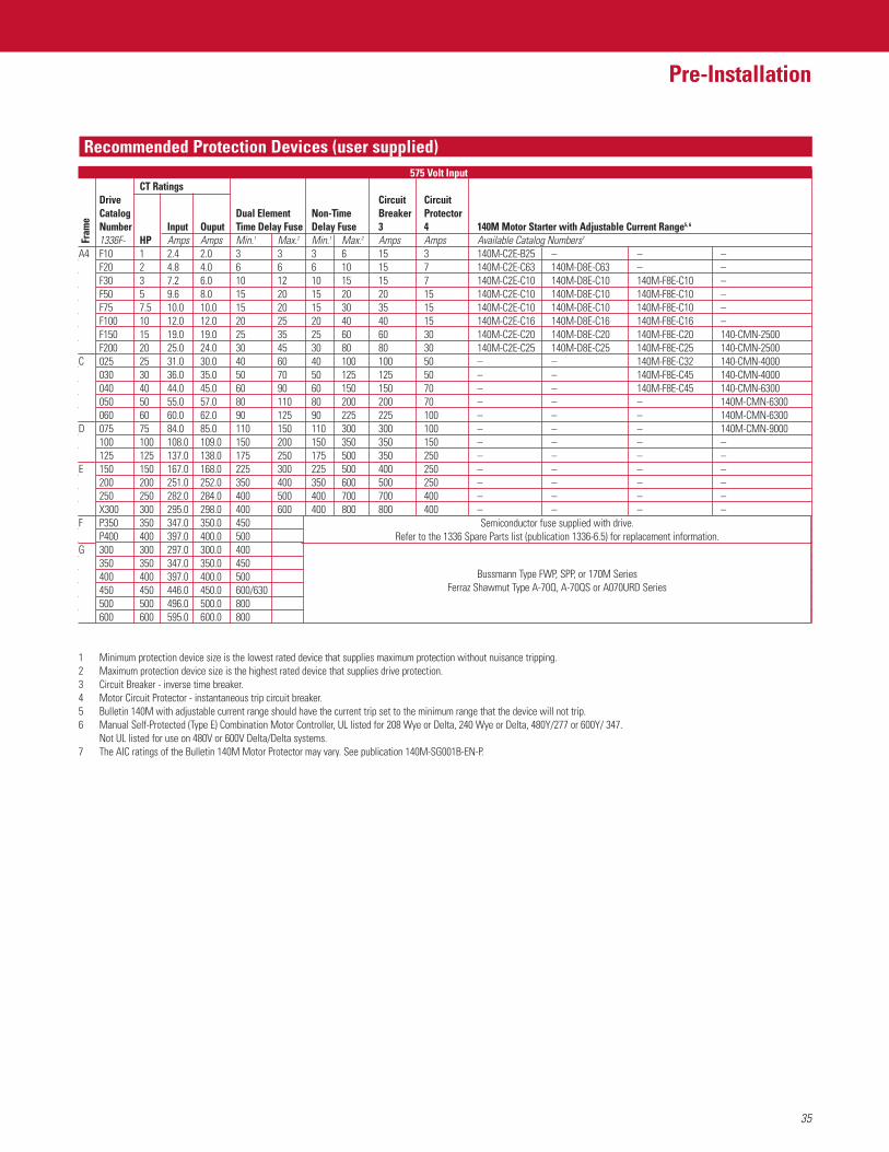
35
Pre-Installation
Recommended Protection Devices (user supplied)
CT RatingsDrive Circuit CircuitCatalog Dual Element Non-Time Breaker ProtectorNumber Input Ouput Time Delay Fuse Delay Fuse 3 4 140M Motor Starter with Adjustable Current Range5, 6
1336F- HP Amps Amps Min.1 Max.2 Min.1 Max.2 Amps Amps Available Catalog Numbers7
A4 F10 1 2.4 2.0 3 3 3 6 15 3 140M-C2E-B25 – – –F20 2 4.8 4.0 6 6 6 10 15 7 140M-C2E-C63 140M-D8E-C63 – –F30 3 7.2 6.0 10 12 10 15 15 7 140M-C2E-C10 140M-D8E-C10 140M-F8E-C10 –F50 5 9.6 8.0 15 20 15 20 20 15 140M-C2E-C10 140M-D8E-C10 140M-F8E-C10 –F75 7.5 10.0 10.0 15 20 15 30 35 15 140M-C2E-C10 140M-D8E-C10 140M-F8E-C10 –F100 10 12.0 12.0 20 25 20 40 40 15 140M-C2E-C16 140M-D8E-C16 140M-F8E-C16 –F150 15 19.0 19.0 25 35 25 60 60 30 140M-C2E-C20 140M-D8E-C20 140M-F8E-C20 140-CMN-2500F200 20 25.0 24.0 30 45 30 80 80 30 140M-C2E-C25 140M-D8E-C25 140M-F8E-C25 140-CMN-2500
C 025 25 31.0 30.0 40 60 40 100 100 50 – – 140M-F8E-C32 140-CMN-4000030 30 36.0 35.0 50 70 50 125 125 50 – – 140M-F8E-C45 140-CMN-4000040 40 44.0 45.0 60 90 60 150 150 70 – – 140M-F8E-C45 140-CMN-6300050 50 55.0 57.0 80 110 80 200 200 70 – – – 140M-CMN-6300060 60 60.0 62.0 90 125 90 225 225 100 – – – 140M-CMN-6300
D 075 75 84.0 85.0 110 150 110 300 300 100 – – – 140M-CMN-9000100 100 108.0 109.0 150 200 150 350 350 150 – – – –125 125 137.0 138.0 175 250 175 500 350 250 – – – –
E 150 150 167.0 168.0 225 300 225 500 400 250 – – – –200 200 251.0 252.0 350 400 350 600 500 250 – – – –250 250 282.0 284.0 400 500 400 700 700 400 – – – –X300 300 295.0 298.0 400 600 400 800 800 400 – – – –
F P350 350 347.0 350.0 450P400 400 397.0 400.0 500
G 300 300 297.0 300.0 400350 350 347.0 350.0 450400 400 397.0 400.0 500450 450 446.0 450.0 600/630500 500 496.0 500.0 800600 600 595.0 600.0 800
1 Minimum protection device size is the lowest rated device that supplies maximum protection without nuisance tripping.2 Maximum protection device size is the highest rated device that supplies drive protection.3 Circuit Breaker - inverse time breaker.4 Motor Circuit Protector - instantaneous trip circuit breaker.5 Bulletin 140M with adjustable current range should have the current trip set to the minimum range that the device will not trip.6 Manual Self-Protected (Type E) Combination Motor Controller, UL listed for 208 Wye or Delta, 240 Wye or Delta, 480Y/277 or 600Y/ 347.
Not UL listed for use on 480V or 600V Delta/Delta systems.7 The AIC ratings of the Bulletin 140M Motor Protector may vary. See publication 140M-SG001B-EN-P.
A4
C
D
E
F
G
575 Volt Input
Semiconductor fuse supplied with drive.Refer to the 1336 Spare Parts list (publication 1336-6.5) for replacement information.
Bussmann Type FWP, SPP, or 170M SeriesFerraz Shawmut Type A-70Q, A-70QS or A070URD Series
Fram
e
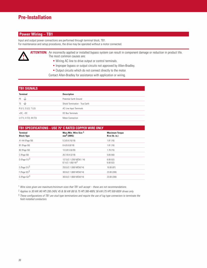
36
Pre-Installation
Power Wiring – TB1Input and output power connections are performed through terminal block, TB1. For maintenance and setup procedures, the drive may be operated without a motor connected.
ATTENTION: An incorrectly applied or installed bypass system can result in component damage or reduction in product life. The most common causes are:
• Wiring AC line to drive output or control terminals.• Improper bypass or output circuits not approved by Allen-Bradley.• Output circuits which do not connect directly to the motor.
Contact Allen-Bradley for assistance with application or wiring.
TB1 SPECIFICATIONS – USE 75° C RATED COPPER WIRE ONLYTerminal Max./Min. Wire Size 1 Maximum TorqueBlock Type mm2 (AWG) N-m (lb.-in.)
A1-A4 (Page 50) 5.3/0.8 (10/18) 1.81 (16)
B1 (Page 50) 8.4/0.8 (8/18) 1.81 (16)
B2 (Page 50) 13.3/0.5 (6/20) 1.70 (15)
C (Page 50) 26.7/0.8 (3/18) 5.65 (50)
D (Page 51)3 127.0/2.1 (250 MCM / 14) 6.00 (52)67.4/2.1 (00/14)2 6.00 (52)
E (Page 51)3 253.0/2.1 (500 MCM/14) 10.00 (87)
F (Page 52)3 303.6/2.1 (600 MCM/14) 23.00 (200)
G (Page 52)3 303.6/2.1 (600 MCM/14) 23.00 (200)
1 Wire sizes given are maximum/minimum sizes that TB1 will accept – these are not recommendations.2 Applies to 30 kW (40 HP) 200-240V, 45 & 56 kW (60 & 75 HP) 380-480V, 56 kW (75 HP) 500-600V drives only.3 These configurations of TB1 are stud type terminations and require the use of lug type connectors to terminate the
field installed conductors.
TB1 SIGNALS
Terminal Description
PE Potential Earth Ground
TE Shield Termination - True Earth
R (L1), S (L2), T (L3) AC Line Input Terminals
+DC, –DC DC Bus Terminals
U (T1), V (T2), W (T3) Motor Connection
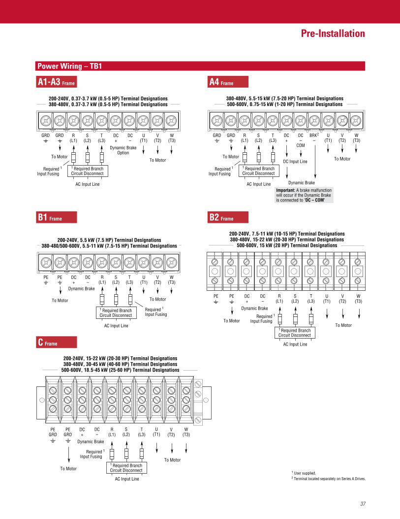
37
Pre-Installation
FeaturesPower Wiring – TB1
GRD GRDGRD GRD R(L1)
S(L2)
T(L3)
DC+
BRK 2–
DC–
COM
U(T1)
V(T2)
W(T3)
AC Input Line
To Motor
380-480V, 5.5-15 kW (7.5-20 HP) Terminal Designations500-600V, 0.75-15 kW (1-20 HP) Terminal Designations
PE PE R(L1)
S(L2)
T(L3)
U(T1)
V(T2)
W(T3)
DC+
DC–
AC Input Line
To Motor
To Motor
To Motor
200-240V, 5.5 kW (7.5 HP) Terminal Designations380-480/500-600V, 5.5-11 kW (7.5-15 HP) Terminal Designations
Dynamic Brake
Dynamic Brake
RequiredInput Fusing
1
To Motor
RequiredInput Fusing
1
RequiredInput Fusing
1
1 User supplied.
PE PE R(L1)
S(L2)
T(L3)
U(T1)
V(T2)
W(T3)
DC+
DC–
RequiredInput Fusing
AC Input Line
To Motor
200-240V, 7.5-11 kW (10-15 HP) Terminal Designations380-480V, 15-22 kW (20-30 HP) Terminal Designations
500-600V, 15 kW (20 HP) Terminal Designations
Dynamic Brake
To Motor1
1 Required BranchCircuit Disconnect
1 Required BranchCircuit Disconnect
1 Required BranchCircuit Disconnect
R(L1)
S(L2)
T(L3)
DC+
DC–
U(T1)
V(T2)
W(T3)
AC Input Line
To Motor
200-240V, 0.37-3.7 kW (0.5-5 HP) Terminal Designations380-480V, 0.37-3.7 kW (0.5-5 HP) Terminal Designations
Dynamic BrakeOption
DC Input Line
2 Terminal located separately on Series A Drives.
1 Required BranchCircuit Disconnect
Important: A brake malfunctionwill occur if the Dynamic Brakeis connected to "DC – COM"
PEGRD
PEGRD
DC+
Dynamic Brake
RequiredInput Fusing
1
DC–
R(L1)
S(L2)
T(L3)
W(T3)
U(T1)
V(T2)
To Motor
AC Input Line
200-240V, 15-22 kW (20-30 HP) Terminal Designations380-480V, 30-45 kW (40-60 HP) Terminal Designations
500-600V, 18.5-45 kW (25-60 HP) Terminal Designations
1 Required BranchCircuit DisconnectTo Motor
A1-A3 Frame A4 Frame
B1 Frame
C Frame
B2 Frame
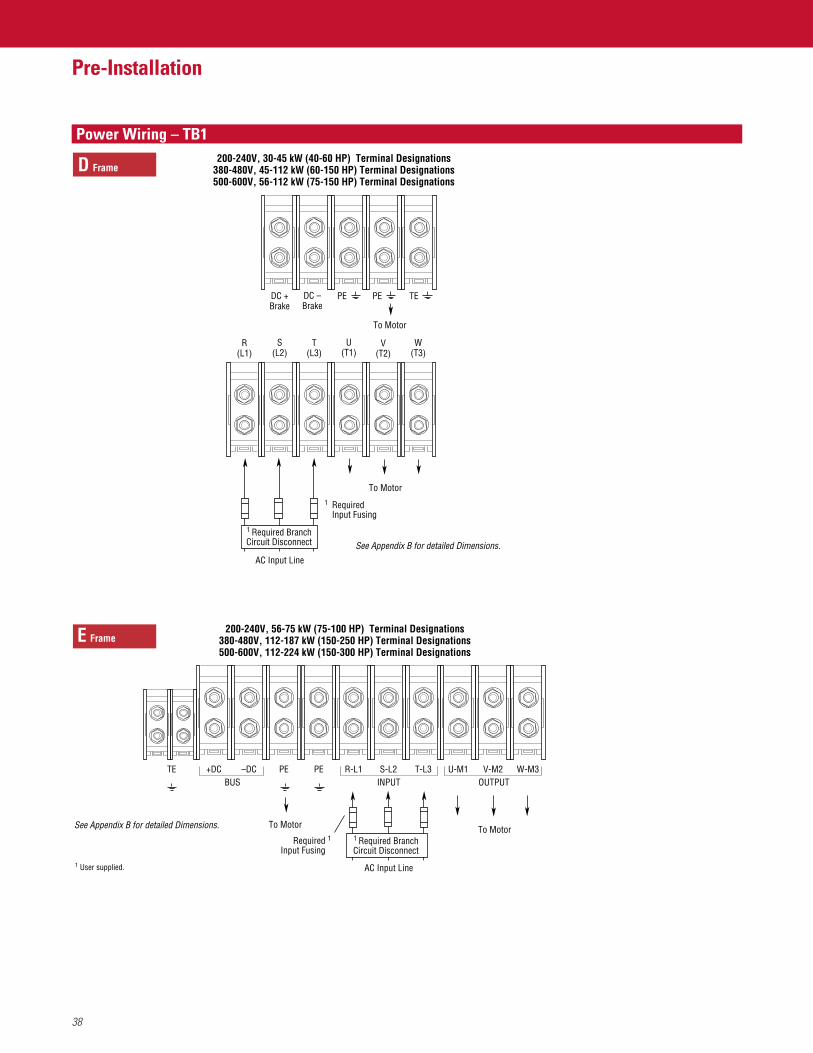
38
Pre-Installation
FeaturesPower Wiring – TB1
PE PE TEDC +Brake
RequiredInput Fusing
1
DC –Brake
R(L1)
S(L2)
T(L3)
W(T3)
U(T1)
V(T2)
To Motor
AC Input Line
200-240V, 30-45 kW (40-60 HP) Terminal Designations380-480V, 45-112 kW (60-150 HP) Terminal Designations500-600V, 56-112 kW (75-150 HP) Terminal Designations
1 Required BranchCircuit Disconnect
To Motor
See Appendix B for detailed Dimensions.
1 User supplied.
200-240V, 56-75 kW (75-100 HP) Terminal Designations380-480V, 112-187 kW (150-250 HP) Terminal Designations500-600V, 112-224 kW (150-300 HP) Terminal Designations
TEBUS INPUT OUTPUT
–DC+DC PE PE R-L1 S-L2 T-L3 U-M1 V-M2 W-M3
RequiredInput Fusing
1To Motor
AC Input Line
1 Required BranchCircuit Disconnect
To MotorSee Appendix B for detailed Dimensions.
D Frame
E Frame
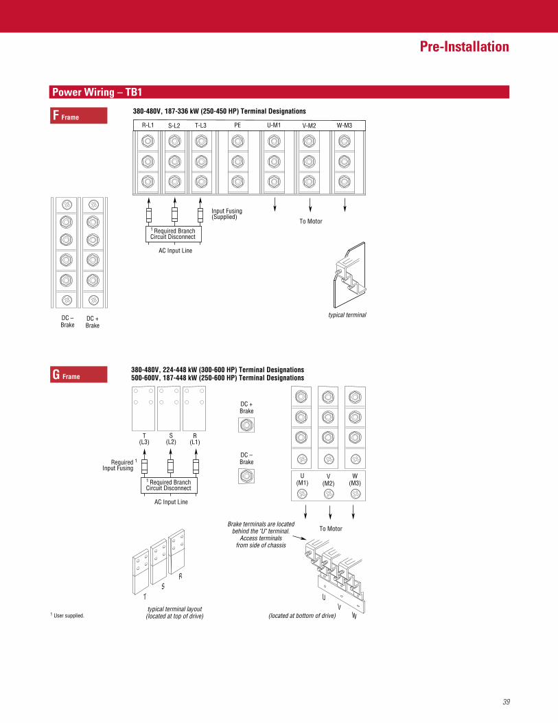
39
Pre-Installation
FeaturesPower Wiring – TB1
DC +Brake
R(L1)
S(L2)
T(L3)
RS
T
380-480V, 224-448 kW (300-600 HP) Terminal Designations500-600V, 187-448 kW (250-600 HP) Terminal Designations
To Motor
DC –BrakeRequired
Input Fusing1
AC Input Line
typical terminal layout(located at top of drive)
typical terminal
Brake terminals are locatedbehind the "U" terminal.
Access terminalsfrom side of chassis
(located at bottom of drive)
W(M3)
U(M1)
V(M2)
W
UV
380-480V, 187-336 kW (250-450 HP) Terminal Designations
To Motor
T-L3R-L1 S-L2 W-M3U-M1PE V-M2F Frame
1 Required BranchCircuit Disconnect
1 User supplied.
Input Fusing(Supplied)
AC Input Line
1 Required BranchCircuit Disconnect
DC –Brake
DC +Brake
G Frame

40
Pre-Installation
FeaturesControl and Signal WiringGeneral Wiring InformationGeneral requirements for analog signal wire include: stranded copper 0.750-0.283 mm2 (18-22 AWG), twisted-pair, 100% shield with drainwire, 300V minimum insulation rating and a temperature rating suitable for the application (not less than 60 degrees C). The recommendedsignal (analog I/O) wire is: • Belden 8760/9460 (or equiv.) – 0.750 mm2 (18 AWG), twisted pair, shielded.• Belden 8770 (or equiv.) – 0.750 mm2 (18 AWG), 3 conductor, shielded for remote pot only.
The recommended wire for encoder inputs/outputs is:• Lengths less than or equal to 30 meters (98 feet) Belden 9730 (or equiv.) – 0.196 mm2 (24 AWG), individually shielded• Lengths greater than 30 meters (98 feet) Belden 9773 (or equiv.) – 0.750 mm2 (18 AWG), twisted pair, shielded
Signal ConnectionsIf the drive control connections are to be linked to an electronic circuit or device, the common or 0V line should, if possible, be grounded atthe device (source) end only.Important: Signal Common – User speed reference signals are terminated to logic common at TB2, terminal 5. This puts the negative
(or common) side of these signals at earth ground potential. Control schemes must be examined for possible conflicts with this type of grounding scheme.
Shield Termination – TE (True Earth)The TE terminal block (not available on 0.37-7.5 kW (0.5-10 HP) A Frame drives) provides a terminating point for signal wiring shields. The maximum and minimum wire size accepted by this block is 2.1 and 0.30 mm2 (14 and 22 AWG). Maximum torque is 1.36 N-m (12 lb.-in.). Use Copper wire only and always separate control and power cabling.
Cable RoutingIf unshielded cable is used, control signal circuits should not run parallel to motor cables or unfiltered supply cables with a spacing lessthan 0.3 meters (1 foot). Cable tray metal dividers or separate conduit should be used.Important: When user-installed control and signal wiring with an insulation rating of less than 600V is used, this wiring must be routed
inside the drive enclosure and separated from any other wiring and/or uninsulated live parts.
41
Pre-Installation
FeaturesTerminal Block – TB2
Terminal Block – TB3
TB2 is located at the bottom of the Main Control Board. 0.37-7.5 kW (0.5-10 HP) A Frame drives have 18 positions. Remaining frame sizes from 5.5 kW (7.5 HP) and up have 22 positions. The maximum and minimum wire size accepted by TB2 is 2.1 and 0.30 mm2 (14 and 22 AWG). Maximum torque for all terminals is 1.36 N-m (12 lb.-in.). Use Copper wire only.
The Control Interface Option provides a means of interfacing various signals and commands to the 1336 PLUS II by using contact closures.Six different versions of the option are available:• L4 Contact Closure Interface1• L4E/L7E2 Contact Closure Interface1 with Encoder Feedback Inputs• L5 +24V AC/DC Interface• L5E/L8E2 +24V AC/DC Interface with Encoder Feedback Inputs• L6 115V AC Interface• L6E/L9E2 115V AC Interface with Encoder Feedback Inputs
The user inputs are connected to the option board through TB3 (see Figure 2.1 for location). The L4, L5 and L6 options each have nine controlinputs. The function of each input must be selected through programming as explained later in this section. The L4E/L7E, L5E/L8E andL6E/L9E2 options are similar to L4, L5 and L6 with the addition of encoder feedback inputs. Refer to Appendix A in Pub. 1336 PLUS – 5.3 forinput impedance values.The maximum and minimum wire size accepted by TB3 is 2.1 and 0.30mm2 (14 and 22 AWG). Recommended torque for all terminals is 0.90-1.13 N-m (8-10 lb.-in.). Use Copper wire only.
Digital InputsDigital inputs are connected at TB3.
Input Mode SelectA number of combinations are available by first programming [Input Mode] to the desired control scheme (i.e. 2-wire, 3-wire or Status). The remaining inputs can then be configured by programming [TB3 Term 22 Sel] through [TB3 term 28 Sel]. Refer to the Digital I/Oparameter group in Chapter 6 of Pub. 1336 PLUS – 5.3 for programming information.
1 Uses internal +5V DC supply.2 The encoder loss detection feature of the 1336 PLUS II requires the use of L7E, L8E or L9E.
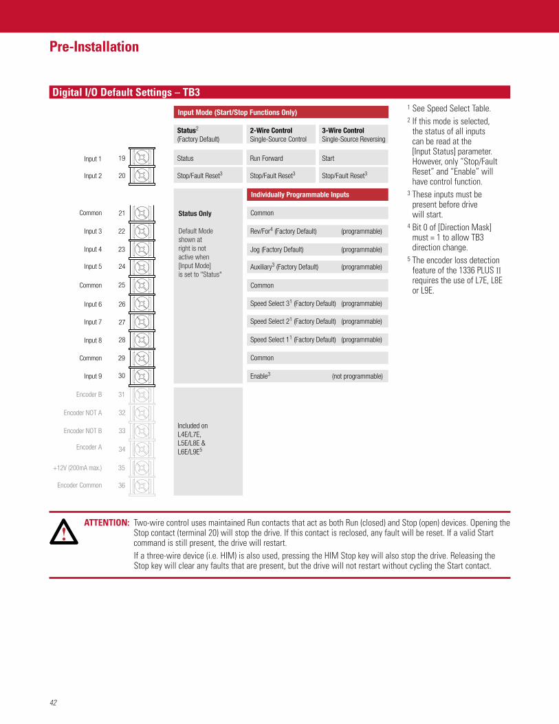
42
Pre-Installation
FeaturesDigital I/O Default Settings – TB3
19
20
21
22
23
24
25
26
27
28
29
30
Input Mode (Start/Stop Functions Only)
Status2
(Factory Default)
Status
Stop/Fault Reset3
2-Wire ControlSingle-Source Control
Run Forward
Stop/Fault Reset3
3-Wire ControlSingle-Source Reversing
Start
Stop/Fault Reset3
Common
Rev/For4 (Factory Default) (programmable)
Individually Programmable Inputs
Jog (Factory Default) (programmable)
Auxiliary3 (Factory Default) (programmable)
Common
Speed Select 31 (Factory Default) (programmable)
Speed Select 21 (Factory Default) (programmable)
Speed Select 11 (Factory Default) (programmable)
Common
Enable3 (not programmable)
Status Only
Default Modeshown at right is not active when[Input Mode] is set to "Status"
Input 1
Input 2
Common
Input 3
Input 4
Input 5
Common
Input 6
Input 7
Input 8
Common
Input 9
Encoder B
Encoder NOT A
Encoder NOT B
Encoder A
+12V (200mA max.)
Encoder Common
31
32
33
34
35
36
Included onL4E/L7E, L5E/L8E & L6E/L9E5
1 See Speed Select Table.2 If this mode is selected,
the status of all inputs can be read at the [Input Status] parameter.However, only “Stop/FaultReset” and “Enable” willhave control function.
3 These inputs must bepresent before drive will start.
4 Bit 0 of [Direction Mask]must = 1 to allow TB3direction change.
5 The encoder loss detectionfeature of the 1336 PLUS IIrequires the use of L7E, L8Eor L9E.
ATTENTION: Two-wire control uses maintained Run contacts that act as both Run (closed) and Stop (open) devices. Opening theStop contact (terminal 20) will stop the drive. If this contact is reclosed, any fault will be reset. If a valid Startcommand is still present, the drive will restart.If a three-wire device (i.e. HIM) is also used, pressing the HIM Stop key will also stop the drive. Releasing theStop key will clear any faults that are present, but the drive will not restart without cycling the Start contact.
43
Pre-Installation
FeaturesDigital I/O Default Settings – TB3Available Functions for Inputs 3 through 8A variety of combinations made up of the following inputs are available.
Input Description
1st/2nd Accel Closing these inputs (1st or 2nd Accel, 1st or 2nd Decel) commands the corresponding 1st/2nd Decel rate. If both inputs are open or both are closed, the current rate is maintained.
1st/2nd Accel/Decel Allows selection of the accel or decel time used by the drive. 1=2nd, 0=1st
Auxiliary Faults the drive via external devices (i.e. motor thermoswitch, O.L. relays, etc.). Opening this contact will fault (F02 - Aux Fault) the drive and shut the output off, ignoring the programmed stop mode.
Clear Fault If drive has faulted, closing this input will clear the fault.
Digital Pot (MOP) These inputs increase (up) or decrease (down) the drive commanded frequency when MOP (Motor Operated Up/Down Potentiometer) is chosen as the frequency command source. The rate of increase/decrease is programmable.
Forward Closing these inputs (Forward or Reverse) commands the corresponding direction. If both inputs are open orboth are closed, the current direction is maintained.
Forward/Reverse Available only with three-wire control - Closing this input commands reverse direction and opening this inputcommands forward direction.
Jog Closing this input starts the drive and causes it to run at programmed jog frequency. Opening this input stopsthe drive using the programmed stop mode.
Line Loss Closing this input gives exclusive control of drive logic to the inputs at terminal blockTB3. No other devices may issue logic commands (excluding Stop) to the drive.
Output Contactor Closed Output contactor auxiliary contact indicates that the output contactor is closed.
Reverse See "Forward" above.
PI Enable Enables the output of the process PI loop.
PI Reset Opening this input clamps the process PI integrator value at zero. Closing this input allows the integrator tocontinue to operate.
Run Reverse Available only with two-wire control - Closing this input issues both a start command and a reverse commandto the drive. Opening the input issues a stop command to the drive.
Speed Select 1, 2, 3 These inputs choose the frequency command source for the drive. See following pages for details.
Stop Type Closing this input selects the stop mode in [Stop Select 2] as the method of stopping when a stop command is issued. Opening this input selects the stop mode in [Stop Select 1] as the method of stopping.
Sync Normally wired to multiple drives – When the Sync input is low, the drive operates normally. When the input is high, the speed of the drive will be held constant and the speed command will have no effect. During thisperiod the speed input of the drive will normally be changed to a different source and/or value. Allowssynchronized change of frequency command to multiple drives.
Traverse Setting this input low disables the traverse function. When the input is high, the traverse function will beactive. [Speed Control] must also be set to "P Jump" for the function to be active.
Important: If a Control Interface Option is not installed, the [Input Mode] parameter must be set to “Status” (default) and jumpers must beinstalled. If the drive was shipped from the factory without the option, these jumpers will have been installed.
Important: The [Input Mode] and [TB3 Term 22-28 Sel] parameters can be changed at any time, but the change will not affect driveoperation until power to the drive has been removed and bus voltage has decayed completely. When changing either parameter,it is important to note that the functions of the Start and Stop inputs will change when power is reapplied to the drive.
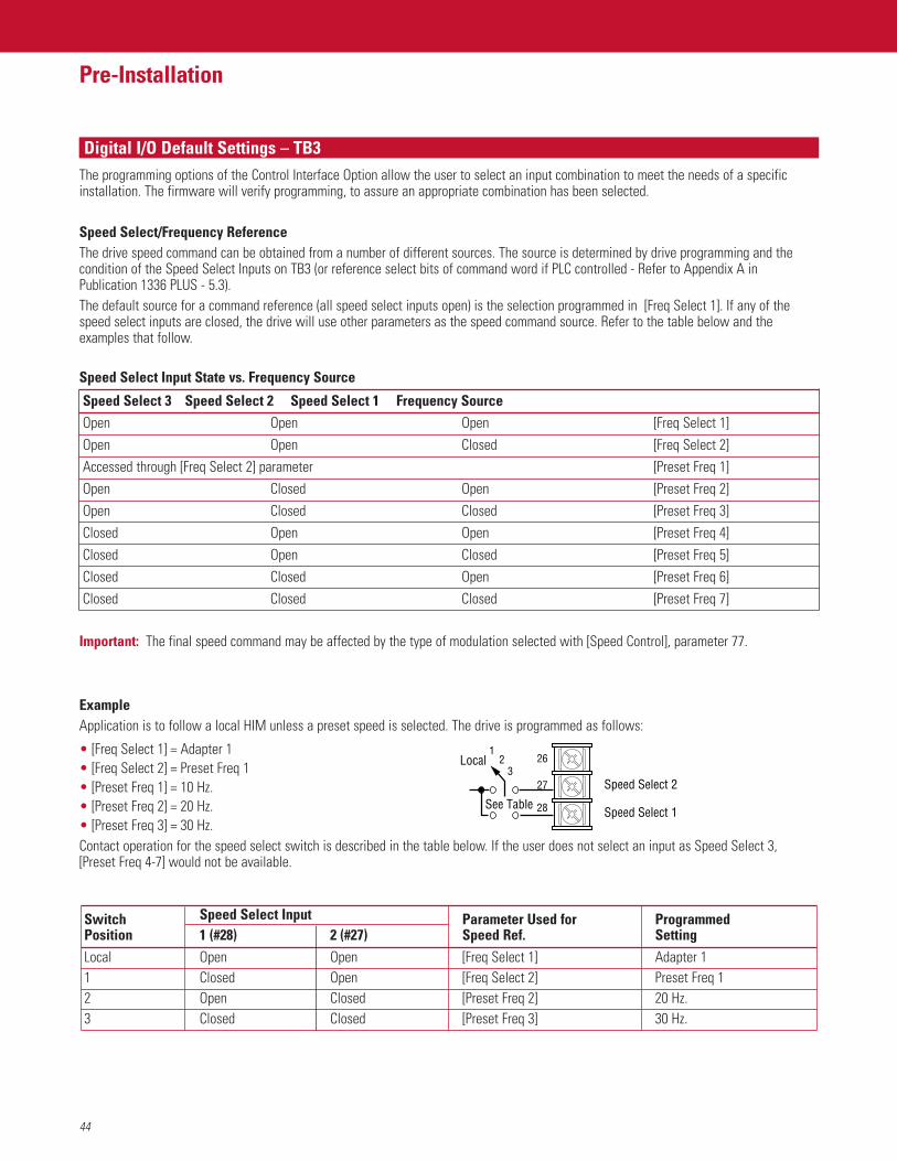
44
Pre-Installation
FeaturesDigital I/O Default Settings – TB3The programming options of the Control Interface Option allow the user to select an input combination to meet the needs of a specificinstallation. The firmware will verify programming, to assure an appropriate combination has been selected.
Speed Select/Frequency ReferenceThe drive speed command can be obtained from a number of different sources. The source is determined by drive programming and thecondition of the Speed Select Inputs on TB3 (or reference select bits of command word if PLC controlled - Refer to Appendix A inPublication 1336 PLUS - 5.3).The default source for a command reference (all speed select inputs open) is the selection programmed in [Freq Select 1]. If any of thespeed select inputs are closed, the drive will use other parameters as the speed command source. Refer to the table below and the examples that follow.
Speed Select Input State vs. Frequency Source
Speed Select 3 Speed Select 2 Speed Select 1 Frequency SourceOpen Open Open [Freq Select 1]Open Open Closed [Freq Select 2]Accessed through [Freq Select 2] parameter [Preset Freq 1]Open Closed Open [Preset Freq 2]Open Closed Closed [Preset Freq 3]Closed Open Open [Preset Freq 4]Closed Open Closed [Preset Freq 5]Closed Closed Open [Preset Freq 6]Closed Closed Closed [Preset Freq 7]
Important: The final speed command may be affected by the type of modulation selected with [Speed Control], parameter 77.
ExampleApplication is to follow a local HIM unless a preset speed is selected. The drive is programmed as follows:
• [Freq Select 1] = Adapter 1• [Freq Select 2] = Preset Freq 1• [Preset Freq 1] = 10 Hz.• [Preset Freq 2] = 20 Hz.• [Preset Freq 3] = 30 Hz.Contact operation for the speed select switch is described in the table below. If the user does not select an input as Speed Select 3, [Preset Freq 4-7] would not be available.
Switch Speed Select Input Parameter Used for ProgrammedPosition 1 (#28) 2 (#27) Speed Ref. SettingLocal Open Open [Freq Select 1] Adapter 11 Closed Open [Freq Select 2] Preset Freq 12 Open Closed [Preset Freq 2] 20 Hz.3 Closed Closed [Preset Freq 3] 30 Hz.
261
23
27
28
Speed Select 2
Speed Select 1
Local
See Table
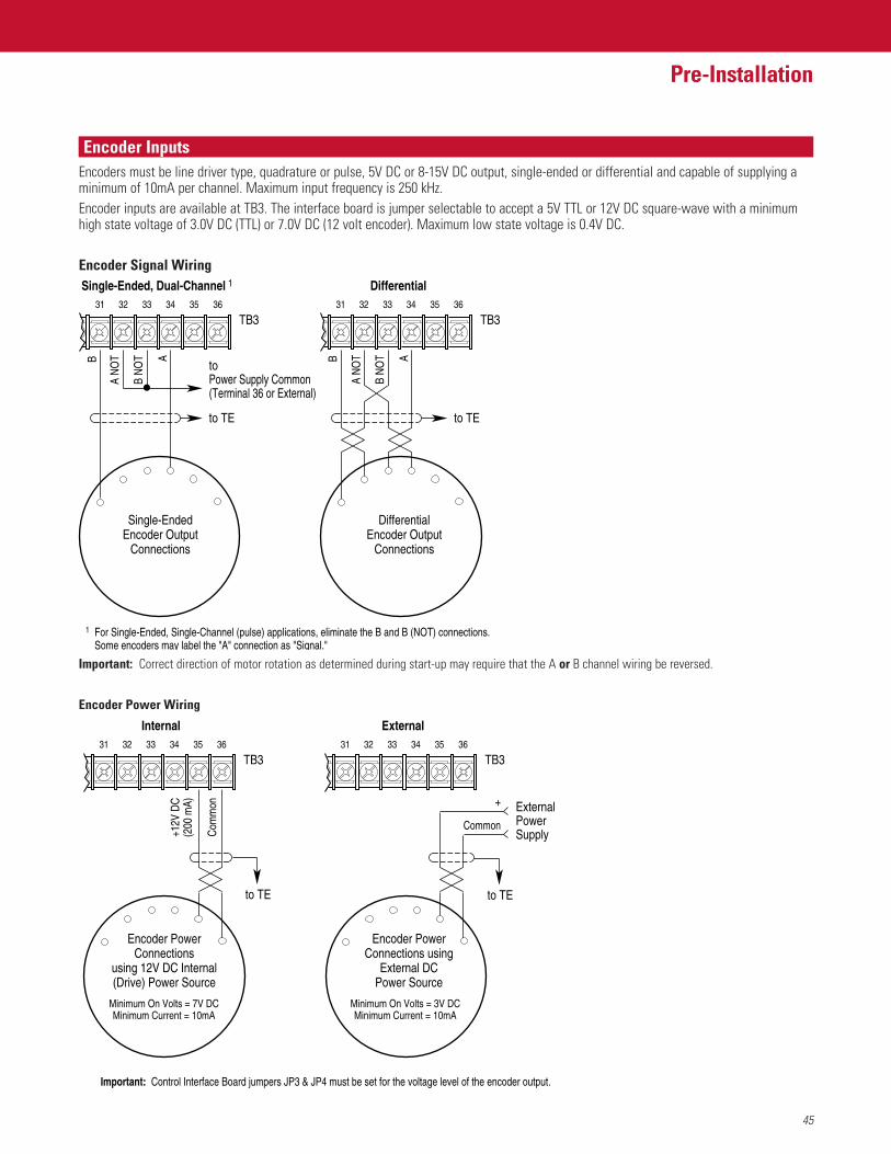
45
Pre-Installation
FeaturesEncoder InputsEncoders must be line driver type, quadrature or pulse, 5V DC or 8-15V DC output, single-ended or differential and capable of supplying aminimum of 10mA per channel. Maximum input frequency is 250 kHz.Encoder inputs are available at TB3. The interface board is jumper selectable to accept a 5V TTL or 12V DC square-wave with a minimumhigh state voltage of 3.0V DC (TTL) or 7.0V DC (12 volt encoder). Maximum low state voltage is 0.4V DC.
Encoder Signal Wiring
31
Single-Ended, Dual-Channel 1 Differential
Single-EndedEncoder Output
Connections
DifferentialEncoder Output
Connections
32 33 34 35 36
A
B N
OT
A N
OTB
31
TB332 33 34 35 36
to TE
A
B N
OT
A N
OTB
TB3
to TE
toPower Supply Common(Terminal 36 or External)
1 For Single-Ended, Single-Channel (pulse) applications, eliminate the B and B (NOT) connections.Some encoders may label the "A" connection as "Signal."
Important: Correct direction of motor rotation as determined during start-up may require that the A or B channel wiring be reversed.
Encoder Power Wiring
Com
mon
+12V
DC
(200
mA)
31
TB3
to TE
Internal External
Encoder PowerConnections
using 12V DC Internal (Drive) Power Source
Encoder PowerConnections using
External DCPower Source
32 33 34 35 36
+
Common
ExternalPowerSupply
31
TB332 33 34 35 36
Important: Control Interface Board jumpers JP3 & JP4 must be set for the voltage level of the encoder output.
Minimum On Volts = 7V DCMinimum Current = 10mA
Minimum On Volts = 3V DCMinimum Current = 10mA
to TE
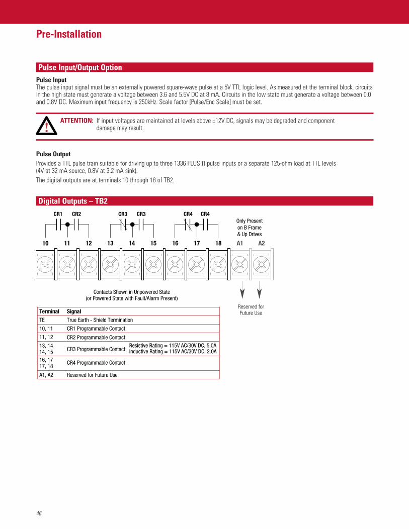
46
Pre-Installation
FeaturesPulse Input/Output OptionPulse InputThe pulse input signal must be an externally powered square-wave pulse at a 5V TTL logic level. As measured at the terminal block, circuitsin the high state must generate a voltage between 3.6 and 5.5V DC at 8 mA. Circuits in the low state must generate a voltage between 0.0and 0.8V DC. Maximum input frequency is 250kHz. Scale factor [Pulse/Enc Scale] must be set.
ATTENTION: If input voltages are maintained at levels above ±12V DC, signals may be degraded and component damage may result.
Pulse OutputProvides a TTL pulse train suitable for driving up to three 1336 PLUS II pulse inputs or a separate 125-ohm load at TTL levels (4V at 32 mA source, 0.8V at 3.2 mA sink).The digital outputs are at terminals 10 through 18 of TB2.
Only Presenton B Frame& Up Drives
Reserved forFuture Use
CR2CR1 CR3CR3 CR4CR4
10 11 12 13 14 15 16 17 18 A1 A2
Terminal
TE
10, 11
11, 12
13, 1414, 1516, 1717, 18
A1, A2
Signal
True Earth - Shield Termination
CR1 Programmable Contact
CR2 Programmable Contact
CR3 Programmable Contact
CR4 Programmable Contact
Reserved for Future Use
Resistive Rating = 115V AC/30V DC, 5.0AInductive Rating = 115V AC/30V DC, 2.0A
Contacts Shown in Unpowered State(or Powered State with Fault/Alarm Present)
Digital Outputs – TB2
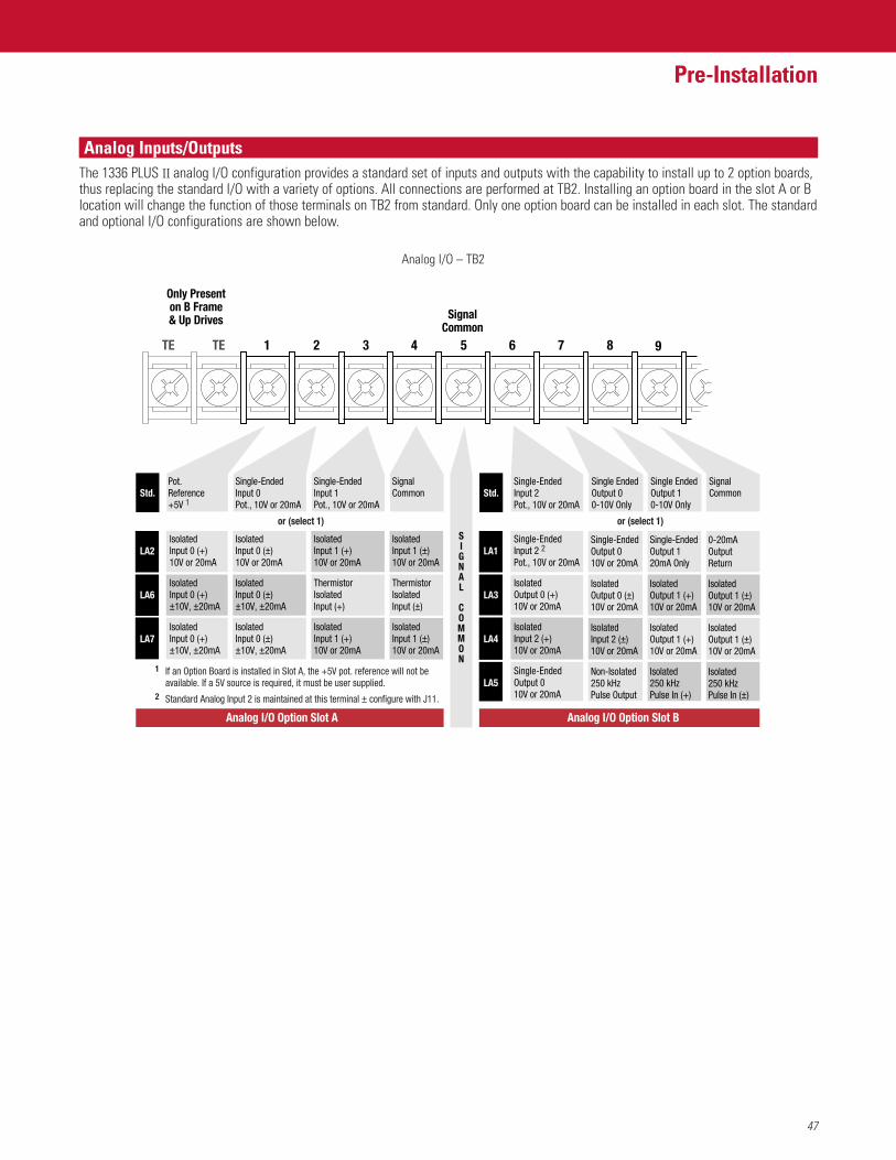
47
Pre-Installation
FeaturesAnalog Inputs/OutputsThe 1336 PLUS II analog I/O configuration provides a standard set of inputs and outputs with the capability to install up to 2 option boards,thus replacing the standard I/O with a variety of options. All connections are performed at TB2. Installing an option board in the slot A or Blocation will change the function of those terminals on TB2 from standard. Only one option board can be installed in each slot. The standardand optional I/O configurations are shown below.
1TE TE
SignalCommon
Only Presenton B Frame& Up Drives
2 3 4 5 6 987
IsolatedInput 0 (±)10V or 20mA
IsolatedInput 0 (±)±10V, ±20mA
IsolatedInput 0 (±)±10V, ±20mA
IsolatedInput 0 (+)10V or 20mA
IsolatedInput 0 (+)±10V, ±20mA
IsolatedInput 0 (+)±10V, ±20mA
LA2
LA6
LA7
Analog I/O Option Slot A Analog I/O Option Slot B
IsolatedInput 1 (+)10V or 20mA
ThermistorIsolatedInput (+)
IsolatedInput 1 (+)10V or 20mA
IsolatedInput 1 (±)10V or 20mA
ThermistorIsolatedInput (±)
IsolatedInput 1 (±)10V or 20mA
Pot.Reference+5V 1
Single-EndedInput 0Pot., 10V or 20mA
Single-EndedInput 1Pot., 10V or 20mA
SignalCommon
SIGNAL COMMON
Std.
LA1
LA3
LA4
LA5
Std.
or (select 1) or (select 1)
Single-EndedInput 2 2Pot., 10V or 20mA
IsolatedOutput 0 (+)10V or 20mA
IsolatedInput 2 (+)10V or 20mA
Single-EndedOutput 010V or 20mA
Single-EndedOutput 010V or 20mA
IsolatedOutput 0 (±)10V or 20mA
IsolatedInput 2 (±)10V or 20mA
Non-Isolated250 kHzPulse Output
Single-EndedOutput 120mA Only
IsolatedOutput 1 (+)10V or 20mA
IsolatedOutput 1 (+)10V or 20mA
Isolated250 kHzPulse In (+)
0-20mAOutputReturn
IsolatedOutput 1 (±)10V or 20mA
IsolatedOutput 1 (±)10V or 20mA
Isolated250 kHzPulse In (±)
SignalCommon
Single EndedOutput 10-10V Only
Single EndedOutput 00-10V Only
Single-EndedInput 2Pot., 10V or 20mA
1 If an Option Board is installed in Slot A, the +5V pot. reference will not be available. If a 5V source is required, it must be user supplied.
2 Standard Analog Input 2 is maintained at this terminal ± configure with J11.
Analog I/O – TB2
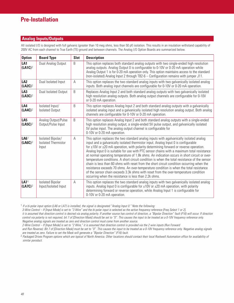
48
Pre-Installation
FeaturesAnalog Inputs/Outputs
Option Board Type Slot DescriptionLA1 Dual Analog Output B This option replaces both standard analog outputs with two single-ended high resolution(LA1C)2 analog outputs. Analog Output 0 is configurable to 0-10V or 0-20 mA operation while
Analog Output 1 is for 0-20 mA operation only. This option maintains access to the standard(non-isolated) Analog Input 2 through TB2-6 – Configuration remains with jumper J11.
LA2 Dual Isolated Input A This option replaces the two standard analog inputs with two galvanically isolated analog (LA2C)2 inputs. Both analog input channels are configurable for 0-10V or 0-20 mA operation.LA3 Dual Isolated Output B Replaces Analog Input 2 and both standard analog outputs with two galvanically isolated(LA3C)2 high resolution analog outputs. Both analog output channels are configurable for 0-10V
or 0-20 mA operation.LA4 Isolated Input/ B This option replaces Analog Input 2 and both standard analog outputs with a galvanically (LA4C)2 Isolated Output isolated analog input and a galvanically isolated high resolution analog output. Both analog
channels are configurable for 0-10V or 0-20 mA operation.LA5 Analog Output/Pulse B This option replaces Analog Input 2 and both standard analog outputs with a single-ended(LA5C)2 Output/Pulse Input high resolution analog output, a single-ended 5V pulse output, and galvanically isolated
5V pulse input. The analog output channel is configurable for 0-10V or 0-20 mA operation.
LA61 Isolated Bipolar/ A This option replaces the two standard analog inputs with agalvanically isolated analog(LA6C)2 Isolated Thermistor input and a galvanically isolated thermistor input. Analog Input 0 is configurable
Input for ±10V or ±20 mA operation, with polarity determining forward or reverse operation.Analog Input 0 is suitable for use with PTC sensor chains with a maximum total resistanceat normal operating temperature of 1.8k ohms. An indication occurs in short circuit or over-temperature conditions. A short circuit condition is when the total resistance of the sensorchain is less than 60 ohms with reset from the short circuit condition occurring when theresistance exceeds 70 ohms. An over-temperature condition is when the total resistance of the sensor chain exceeds 3.3k ohms with reset from the over-temperature conditionoccurring when the resistance is less than 2.2k ohms.
LA71 Isolated Bipolar A This option replaces the two standard analog inputs with two galvanically isolated analog(LA7C)2 Input/Isolated Input inputs. Analog Input 0 is configurable for ±10V or ±20 mA operation, with polarity
determining forward or reverse operation, while Analog Input 1 is configurable for 0-10V or 0-20 mA operation.
1 If a bi-polar input option (LA6 or LA7) is installed, the signal is designated “Analog Input 0.” Note the following:3-Wire Control – If [Input Mode] is set to “3 Wire” and the bi-polar input is selected as the active frequency reference [Freq Select 1 or 2], it is assumed that direction control is desired via analog polarity. If another source has control of direction, a “Bipolar Direction” fault (F16) will occur. If directioncontrol via polarity is not required, bit 7 of [Direction Mask] should be set to “0”. This causes the input to be treated as a 0-10V frequency reference only.Negative analog signals are treated as zero and direction control must come from another source.2-Wire Control – If [Input Mode] is set to “2 Wire,” it is assumed that direction control is provided via the 2 wire inputs (Run Forward and Run Reverse). Bit 7 of [Direction Mask] must be set to “0”. This causes the input to be treated as a 0-10V frequency reference only. Negative analog signalsare treated as zero. Failure to set the Mask will generate a “Bipolar Direction” (F16) fault.
2 Packaged Drives Program options which are typical of North America. Other locations should contact their local Rockwell Automation office for availability ofsimilar poroduct.
All isolated I/O is designed with full galvanic (greater than 10 meg ohms, less than 50 pf) isolation. This results in an insulation withstand capability of200V AC from each channel to True Earth (TE) ground and between channels. The Analog I/O Option Boards are summarized below.
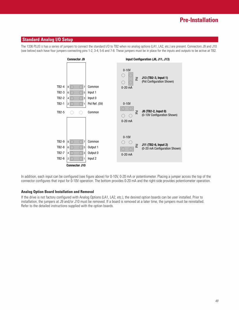
49
Pre-Installation
FeaturesStandard Analog I/O SetupThe 1336 PLUS II has a series of jumpers to connect the standard I/O to TB2 when no analog options (LA1, LA2, etc.) are present. Connectors J9 and J10(see below) each have four jumpers connecting pins 1-2, 3-4, 5-6 and 7-8. These jumpers must be in place for the inputs and outputs to be active at TB2.
In addition, each input can be configured (see figure above) for 0-10V, 0-20 mA or potentiometer. Placing a jumper across the top of theconnector configures that input for 0-10V operation. The bottom provides 0-20 mA and the right-side provides potentiometer operation.
Analog Option Board Installation and RemovalIf the drive is not factory configured with Analog Options (LA1, LA2, etc.), the desired option boards can be user installed. Prior toinstallation, the jumpers at J9 and/or J10 must be removed. If a board is removed at a later time, the jumpers must be reinstalled. Refer to the detailed instructions supplied with the option boards.
Connector J9 Input Configuration (J8, J11, J13)
TB2-4 78 Common
TB2-5 Common
TB2-3 56 Input 1
TB2-2 34 Input 0
TB2-1 12 Pot Ref. (5V)
Connector J10
TB2-9 78 Common
TB2-8 56 Output 1
TB2-7 34 Output 0
TB2-6 12 Input 2
0-10V
J13 (TB2-3, Input 1)(Pot Configuration Shown)
0-20 mA
PotPot
Pot0-10V
J8 (TB2-2, Input 0)(0-10V Configuration Shown)
0-20 mA
0-10V
J11 (TB2-6, Input 2)(0-20 mA Configuration Shown)
0-20 mA
50
Pre-Installation
FeaturesMotor CablesA variety of cable types are acceptable for drive installations. For many installations, unshielded cable is adequate, provided it can beseparated from sensitive circuits. As an approximate guide, allow a spacing of 0.3 meters (1 foot) for every 10 meters (32.8 feet) of length. In all cases, long parallel runs must be avoided. Do not use cable with an insulation thickness less than or equal to 15 mils (0.4mm/0.015 in.).The cable should be 4-conductor with the ground lead being connected directly to the drive ground terminal (PE) and the motor frameground terminal.
Shielded CableShielded cable is recommended if sensitive circuits or devices are connected or mounted to the machinery driven by the motor. The shieldmust be connected to both the drive ground (drive end) and motor frame ground (motor end). The connection must be made at both ends tominimize interference.If cable trays or large conduits are to be used to distribute the motor leads for multiple drives, shielded cable is recommended to reduce orcapture the noise from the motor leads and minimize “cross coupling” of noise between the leads of different drives. The shield should beconnected to the ground connections at both the motor and drive end.Armored cable also provides effective shielding. Ideally it should be grounded only at the drive (PE) and motor frame. Some armored cablehas a PVC coating over the armor to prevent incidental contact with grounded structure. If, due to the type of connector, the armor isgrounded at the cabinet entrance, shielded cable should be used within the cabinet if power leads will be run close to control signals.In some hazardous environments it is not permissible to ground both ends of the cable armor because of the possibility of high currentcirculating at the input frequency if the ground loop is cut by a strong magnetic field. This only applies in the proximity of powerfulelectrical machines. In such cases, consult factory for specific guidelines.
ConduitIf metal conduit is preferred for cable distribution, the following guidelines must be followed. • Drives are normally mounted in cabinets and ground connections are made at a common ground point in the cabinet. Normal installation
of conduit provides grounded connections to both the motor frame ground (junction box) and drive cabinet ground. These groundconnections help minimize interference. This is a noise reduction recommendation only, and does not affect the requirements for safetygrounding.
• No more than three sets of motor leads can be routed through a single conduit. This will minimize “cross talk” that could reduce theeffectiveness of the noise reduction methods described. If more than three drive/motor connections per conduit are required, shieldedcable as previously described must be used. If practical, each conduit should contain only one set of motor leads.
ATTENTION: To avoid a possible shock hazard caused by induced voltages, unused wires in the conduit must be grounded at bothends. For the same reason, if a drive sharing a conduit is being serviced or installed, all drives using this conduitshould be disabled. This will eliminate the possible shock hazard from “cross coupled” drive motor leads.
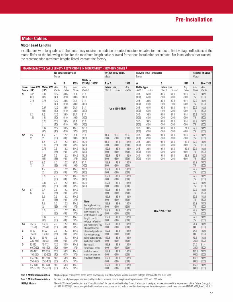
51
Pre-Installation
FeaturesMotor Cables
MAXIMUM MOTOR CABLE LENGTH RESTRICTIONS IN METERS (FEET) - 380V-480V DRIVES 1
No External Devices w/1204-TFB2 Term. w/1204-TFA1 Terminator Reactor at Drive 2
Motor Motor Motor Motor1600V or
A B 1329 1329R/L (1850V) A or B 1329 A B 1329 A B or 1329Drive Drive kW Motor kW Any Any Any Any Cable Type Any Cable Type Cable Type Any Any AnyFrame (HP) (HP) Cable Cable Cable Cable 6 Shld. 3 Unshld. Cable Shld. 3 Unshld. Shld. 3 Unshld. Cable Cable CableA1 0.37 0.37 12.2 33.5 91.4 91.4 30.5 61.0 30.5 61.0 91.4 22.9 182.9
(0.5) (0.5) (40) (110) (300) (300) (100) (200) (100) (200) (300) (75) (600)0.75 0.75 12.2 33.5 91.4 91.4 30.5 30.5 30.5 30.5 91.4 22.9 182.9 (1) (1) (40) (110) (300) (300) (100) (100) (100) (100) (300) (75) (600)
0.37 12.2 33.5 91.4 91.4 30.5 61.0 30.5 61.0 91.4 22.9 182.9 (0.5) (40) (110) (300) (300) (100) (200) (100) (200) (300) (75) (600)
1.2 1.2 12.2 33.5 91.4 91.4 30.5 30.5 61.0 61.0 91.4 22.9 182.9 (1.5) (1.5) (40) (110) (300) (300) (100) (100) (200) (200) (300) (75) (600)
0.75 12.2 33.5 91.4 91.4 30.5 30.5 61.0 61.0 91.4 22.9 182.9 (1) (40) (110) (300) (300) (100) (100) (200) (200) (300) (75) (600)0.37 12.2 33.5 114.3 121.9 30.5 30.5 61.0 61.0 121.9 22.9 182.9 (0.5) (40) (110) (375) (400) (100) (100) (200) (200) (400) (75) (600)
A2 1.5 1.5 7.6 12.2 91.4 91.4 91.4 91.4 91.4 30.5 30.5 91.4 61.0 91.4 22.9 182.9 (2) (2) (25) (40) (300) (300) (300) (300) (300) (100) (100) (300) (200) (300) (75) (600)
1.2 7.6 12.2 114.3 182.9 91.4 182.9 182.9 30.5 30.5 91.4 61.0 182.9 22.9 182.9 (1.5) (25) (40) (375) (600) (300) (600) (600) (100) (100) (300) (200) (600) (75) (600)0.75 7.6 12.2 114.3 182.9 182.9 182.9 182.9 30.5 30.5 91.4 61.0 182.9 22.9 182.9 (1) (25) (40) (375) (600) (600) (600) (600) (100) (100) (300) (200) (600) (75) (600)0.37 7.6 12.2 114.3 182.9 182.9 182.9 182.9 30.5 30.5 91.4 61.0 182.9 22.9 182.9 (0.5) (25) (40) (375) (600) (600) (600) (600) (100) (100) (300) (200) (600) (75) (600)
2.2 2.2 7.6 12.2 91.4 91.4 182.9 182.9 182.9 22.9 182.9 (3) (3) (25) (40) (300) (300) (600) (600) (600) (75) (600)
1.5 7.6 12.2 114.3 182.9 182.9 182.9 182.9 22.9 182.9 (2) (25) (40) (375) (600) (600) (600) (600) (75) (600)0.75 7.6 12.2 114.3 182.9 182.9 182.9 182.9 22.9 182.9 (1) (25) (40) (375) (600) (600) (600) (600) (75) (600)0.37 7.6 12.2 114.3 182.9 182.9 182.9 182.9 22.9 182.9 (0.5) (25) (40) (375) (600) (600) (600) (600) (75) (600)
A3 3.7 3.7 7.6 12.2 114.3 182.9 182.9 182.9 22.9 182.9 (5) (5) (25) (40) (375) (600) (600) (600) (75) (600)
2.2 7.6 12.2 114.3 182.9 182.9 182.9 22.9 182.9 (3) (25) (40) (375) (600) (600) (600) (75) (600)1.5 7.6 12.2 114.3 182.9 182.9 182.9 22.9 182.9 (2) (25) (40) (375) (600) (600) (600) (75) (600)0.75 7.6 12.2 114.3 182.9 182.9 182.9 22.9 182.9 (1) (25) (40) (375) (600) (600) (600) (75) (600)0.37 7.6 12.2 114.3 182.9 182.9 182.9 22.9 182.9 (0.5) (25) (40) (375) (600) (600) (600) (75) (600)
A4 5.5-15 5.5-15 7.6 12.2 114.3 182.9 182.9 182.9 24.4 182.9 (7.5-20) (7.5-20) (25) (40) (375) (600) (600) (600) (80) (600)
B 11-22 11-22 7.6 12.2 114.3 182.9 182.9 182.9 24.4 182.9 (15-30) (15-30) (25) (40) (375) (600) (600) (600) (80) (600)
C 30-45 30-45 7.6 12.2 114.3 182.9 182.9 182.9 76.2 182.9 (X40-X60) (40-60) (25) (40) (375) (600) (600) (600) (250) (600)
D 45-112 45-112 12.2 30.5 114.3 182.9 182.9 182.9 61.0 91.4 (60-X150) (60-150) (40) (100) (375) (600) (600) (600) (200) (300)
E 112-187 112-224 12.2 53.3 114.3 182.9 182.9 182.9 182.9 182.9 (150-250) (150-300) (40) (175) (375) (600) (600) (600) (600) (600)
F 187-336 187-336 18.3 53.3 114.3 182.9 182.9 182.9 182.9 182.9 (250-450) (250-450) (60) (175) (375) (600) (600) (600) (600) (600)
G 187-448 187-448 18.3 53.3 114.3 182.9 182.9 182.9 182.9 182.9 (X250-600) (250-600) (60) (175) (375) (600) (600) (600) (600) (600)
Type A Motor Characteristics: No phase paper or misplaced phase paper, lower quality insulation systems, corona inception voltages between 850 and 1000 volts.
Type B Motor Characteristics: Properly placed phase paper, medium quality insulation systems, corona inception voltages between 1000 and 1200 volts.
1329R/L Motors: These AC Variable Speed motors are “Control-Matched” for use with Allen-Bradley Drives. Each motor is designed to meet or exceed the requirements of the Federal Energy Actof 1992. All 1329R/L motors are optimized for variable speed operation and include premium inverter grade insulation systems which meet or exceed NEMA MG1, Part 31.40.4.2.
NoteFor applications/installations usingnew motors, norestrictions in leadlength due tovoltage reflectionare necessary. Youshould observestandard practicesfor voltage drop,cable capacitance,and other issues.For retrofitsituations, checkwith the motormanufacturer forinsulation rating.
Use 1204-TFA1
Motor Lead LengthsInstallations with long cables to the motor may require the addition of output reactors or cable terminators to limit voltage reflections at themotor. Refer to the following tables for the maximum length cable allowed for various installation techniques. For installations that exceedthe recommended maximum lengths listed, contact the factory.
Use 1204-TFB2
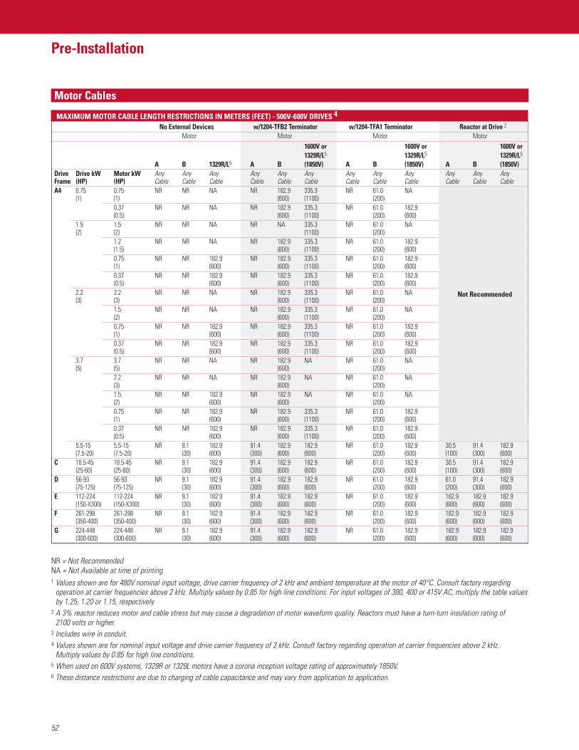
52
Pre-Installation
FeaturesMotor Cables
MAXIMUM MOTOR CABLE LENGTH RESTRICTIONS IN METERS (FEET) - 500V-600V DRIVES 4
No External Devices w/1204-TFB2 Terminator w/1204-TFA1 Terminator Reactor at Drive 2
Motor Motor Motor Motor1600V or 1600V or 1600V or 1329R/L5 1329R/L5 1329R/L5
A B 1329R/L5 A B (1850V) A B (1850V) A B (1850V)Drive Drive kW Motor kW Any Any Any Any Any Any Any Any Any Any Any AnyFrame (HP) (HP) Cable Cable Cable Cable Cable Cable Cable Cable Cable Cable Cable CableA4 0.75 0.75 NR NR NA NR 182.9 335.3 NR 61.0 NA
(1) (1) (600) (1100) (200)0.37 NR NR NA NR 182.9 335.3 NR 61.0 182.9(0.5) (600) (1100) (200) (600)
1.5 1.5 NR NR NA NR NA 335.3 NR 61.0 NA(2) (2) (1100) (200)
1.2 NR NR NA NR 182.9 335.3 NR 61.0 182.9(1.5) (600) (1100) (200) (600)0.75 NR NR 182.9 NR 182.9 335.3 NR 61.0 182.9(1) (600) (600) (1100) (200) (600)0.37 NR NR 182.9 NR 182.9 335.3 NR 61.0 182.9(0.5) (600) (600) (1100) (200) (600)
2.2 2.2 NR NR NA NR 182.9 335.3 NR 61.0 NA(3) (3) (600) (1100) (200)
1.5 NR NR NA NR 182.9 335.3 NR 61.0 NA(2) (600) (1100) (200)0.75 NR NR 182.9 NR 182.9 335.3 NR 61.0 182.9(1) (600) (600) (1100) (200) (600)0.37 NR NR 182.9 NR 182.9 335.3 NR 61.0 182.9(0.5) (600) (600) (1100) (200) (600)
3.7 3.7 NR NR NA NR 182.9 NA NR 61.0 NA(5) (5) (600) (200)
2.2 NR NR NA NR 182.9 NA NR 61.0 NA(3) (600) (200)1.5 NR NR 182.9 NR 182.9 NA NR 61.0 NA(2) (600) (600) (200)0.75 NR NR 182.9 NR 182.9 335.3 NR 61.0 182.9(1) (600) (600) (1100) (200) (600)0.37 NR NR 182.9 NR 182.9 335.3 NR 61.0 182.9(0.5) (600) (600) (1100) (200) (600)
5.5-15 5.5-15 NR 9.1 182.9 91.4 182.9 182.9 NR 61.0 182.9 30.5 91.4 182.9(7.5-20) (7.5-20) (30) (600) (300) (600) (600) (200) (600) (100) (300) (600)
C 18.5-45 18.5-45 NR 9.1 182.9 91.4 182.9 182.9 NR 61.0 182.9 30.5 91.4 182.9(25-60) (25-60) (30) (600) (300) (600) (600) (200) (600) (100) (300) (600)
D 56-93 56-93 NR 9.1 182.9 91.4 182.9 182.9 NR 61.0 182.9 61.0 91.4 182.9(75-125) (75-125) (30) (600) (300) (600) (600) (200) (600) (200) (300) (600)
E 112-224 112-224 NR 9.1 182.9 91.4 182.9 182.9 NR 61.0 182.9 182.9 182.9 182.9(150-X300) (150-X300) (30) (600) (300) (600) (600) (200) (600) (600) (600) (600)
F 261-298 261-298 NR 9.1 182.9 91.4 182.9 182.9 NR 61.0 182.9 182.9 182.9 182.9(350-400) (350-400) (30) (600) (300) (600) (600) (200) (600) (600) (600) (600)
G 224-448 224-448 NR 9.1 182.9 91.4 182.9 182.9 NR 61.0 182.9 182.9 182.9 182.9(300-600) (300-600) (30) (600) (300) (600) (600) (200) (600) (600) (600) (600)
NR = Not RecommendedNA = Not Available at time of printing1 Values shown are for 480V nominal input voltage, drive carrier frequency of 2 kHz and ambient temperature at the motor of 40°C. Consult factory regarding
operation at carrier frequencies above 2 kHz. Multiply values by 0.85 for high line conditions. For input voltages of 380, 400 or 415V AC, multiply the table valuesby 1.25, 1.20 or 1.15, respectively.
2 A 3% reactor reduces motor and cable stress but may cause a degradation of motor waveform quality. Reactors must have a turn-turn insulation rating of 2100 volts or higher.
3 Includes wire in conduit.4 Values shown are for nominal input voltage and drive carrier frequency of 2 kHz. Consult factory regarding operation at carrier frequencies above 2 kHz.
Multiply values by 0.85 for high line conditions.5 When used on 600V systems, 1329R or 1329L motors have a corona inception voltage rating of approximately 1850V.6 These distance restrictions are due to charging of cable capacitance and may vary from application to application.
Not Recommended
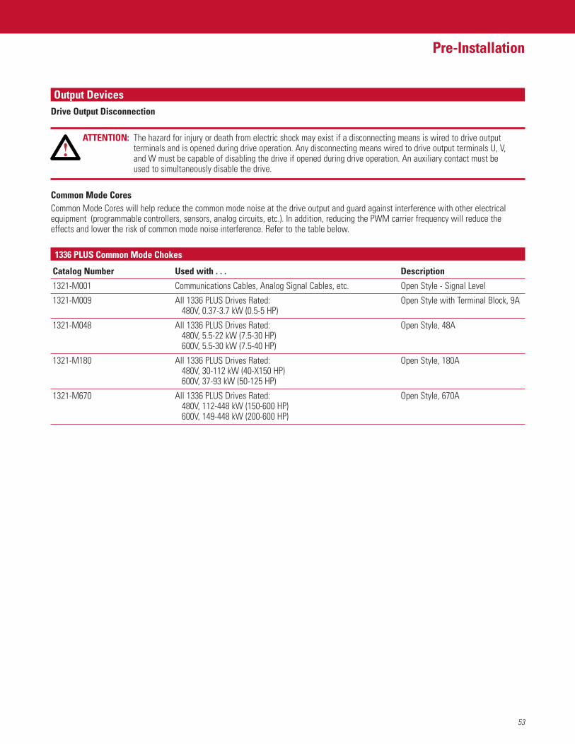
53
Pre-Installation
FeaturesOutput DevicesDrive Output Disconnection
ATTENTION: The hazard for injury or death from electric shock may exist if a disconnecting means is wired to drive outputterminals and is opened during drive operation. Any disconnecting means wired to drive output terminals U, V, and W must be capable of disabling the drive if opened during drive operation. An auxiliary contact must be used to simultaneously disable the drive.
Common Mode CoresCommon Mode Cores will help reduce the common mode noise at the drive output and guard against interference with other electricalequipment (programmable controllers, sensors, analog circuits, etc.). In addition, reducing the PWM carrier frequency will reduce theeffects and lower the risk of common mode noise interference. Refer to the table below.
1336 PLUS Common Mode Chokes
Catalog Number Used with . . . Description
1321-M001 Communications Cables, Analog Signal Cables, etc. Open Style - Signal Level
1321-M009 All 1336 PLUS Drives Rated: Open Style with Terminal Block, 9A480V, 0.37-3.7 kW (0.5-5 HP)
1321-M048 All 1336 PLUS Drives Rated: Open Style, 48A480V, 5.5-22 kW (7.5-30 HP)600V, 5.5-30 kW (7.5-40 HP)
1321-M180 All 1336 PLUS Drives Rated: Open Style, 180A480V, 30-112 kW (40-X150 HP)600V, 37-93 kW (50-125 HP)
1321-M670 All 1336 PLUS Drives Rated: Open Style, 670A480V, 112-448 kW (150-600 HP)600V, 149-448 kW (200-600 HP)
54
Pre-Installation
FeaturesCable TerminationOptional Cable TerminatorVoltage doubling at motor terminals, known as reflected wave phenomenon, standing wave or transmission line effect, can occur whenusing drives with long motor cables.Inverter duty motors with phase-to-phase insulation ratings of 1200 volts or higher should be used to minimize effects of reflected wave on motor insulation life.Applications with non-inverter duty motors or any motor with exceptionally long leads may require an output filter or cable terminator. A filter or terminator will help limit reflection to the motor, to levels which are less than the motor insulation rating. The tables on pages 52 and 53 list the maximum recommended cable length for unterminated cables, since the voltage doublingphenomenon occurs at different lengths for different drive ratings. If your installation requires longer motor cable lengths, a reactor or cable terminator is recommended. Also, refer to these tables for frequency, cable length and voltage restrictions of 1204-TFA1 or 1204-TFB2 terminators.
Optional Output ReactorBulletin 1321 Reactors listed in the 1336 PLUS-3.0 Price Sheet can be used for drive input and output. These reactors are specificallyconstructed to accommodate IGBT inverter applications with switching frequencies up to 20 kHz. They have a UL approved dielectricstrength of 4000 volts, opposed to a normal rating of 2500 volts. The first two and last two turns of each coil are triple insulated to guardagainst insulation breakdown resulting from high dv/dt. When using motor line reactors, it is recommended that the drive PWM frequencybe set to its lowest value to minimize losses in the reactors.
Important: By using an output reactor the effective motor voltage will be lower because of the voltage drop across the reactor - this mayalso mean a reduction of motor torque.
User Supplied Enclosures1336 PLUS II drives installed in user supplied enclosures may be mounted within an enclosure or may be mounted to allow the heatsink toextend outside the enclosure. Use the following information in combination with the enclosure manufacturer’s guidelines for sizing.
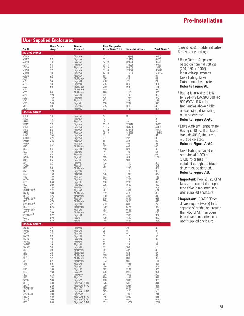
55
Pre-Installation
FeaturesUser Supplied EnclosuresBase Derate Derate Heat Dissipation
Cat No. Amps 1 Curve 2, 3 Drive Watts 2, 3, 4 Heatsink Watts 2 Total Watts 2200-240V DRIVESAQF05 2.3 Figure A 13 (9) 15 (11) 28 (20)AQF07 3.0 Figure A 15 (11) 21 (15) 36 (26)AQF10 4.5 Figure A 17 (12) 32 (23) 49 (35)AQF15 6.0 Figure A 21 (15) 42 (30) 63 (46)AQF20 8.0 Figure A 25 (18) 56 (40) 81 (59)AQF30 12 Figure A 33 (24) 72 (52) 105 (76)AQF50 18 Figure A 42 (30) 116 (84) 158 (114)AQF75 22 Figure A 58 186 244A007 27 No Derate 156 486 642A010 34 Figure B 200 721 921A015 48 Figure D 205 819 1024A020 65 No Derate 210 933 1143A025 77 No Derate 215 1110 1325A030 80 No Derate 220 1110 1330A040 120 Figure G 361 1708 2069A050 150 Figure H 426 1944 2370A060 180 Figure J 522 2664 3186A075 240 Figure L 606 2769 3375A100 291 Figure M 755 3700 4455A125 325 Figure N 902 4100 5002380-480V DRIVESBRF05 1.2 Figure A 12 9 21BRF07 1.7 Figure A 13 15 28BRF10 2.3 Figure A 15 20 35BRF15 3.0 Figure A 16 (12) 27 (21) 43 (33)BRF20 4.0 Figure A 19 (15) 36 (28) 55 (43)BRF30 6.0 Figure A 23 (18) 54 (42) 77 (60)BRF50 9.0 Figure A 29 (23) 84 (65) 113 (88)BRF75 15.4 Figure A 58 186 244BRF100 22.0 Figure A 68 232 300BRF150 24.0 Figure A 88 332 420BRF200 27.0 Figure A 96 356 452B015 27 No Derate 117 486 603B020 34 Figure B 140 628 768B025 42 Figure C 141 720 861B030 48 Figure D 141 820 961BX040 59 Figure E 175 933 1108B040 65 Figure E 175 933 1108B050 77 Figure F 193 1110 1303BX060 77 Figure F 193 1110 1303B060 96 No Derate 361 1708 2069B075 120 Figure G 361 1708 2069B100 150 Figure H 426 1944 2370B125 180 Figure J 522 2664 3186BX150 180 Figure J 606 2769 3375B150 240 Figure L 606 2769 3375B200 292 Figure M 755 3700 4455B250 325 Figure N 902 4100 5002BP/BPR250 6 322 Figure O 491 4658 5149BX250 360 No Derate 902 4100 5002B300 5 425 No Derate 1005 4805 5810BP/BPR300 6 357 Figure P 619 5342 5961B350 5 475 No Derate 1055 5455 6510BP/BPR350 6 421 Figure Q 733 6039 6772B400 5 525 No Derate 1295 6175 7470BP/BPR400 6 471 Figure R 793 6329 7122B450 5 590 No Derate 1335 6875 8210BPBPR450 6 527 Figure S 931 7000 7931B500 5 670 Figure T 1395 7525 8920B600 5 670 Figure T 1485 8767 10252500-600V DRIVESCWF10 2.4 Figure U 25 29 54CWF20 4.8 Figure U 29 57 86CWF30 7.2 Figure U 32 87 119CWF50 9.6 Figure U 35 117 152CWF75 10 Figure U 38 148 186CWF100 12 Figure U 41 177 218CWF150 19 Figure U 52 286 338CWF200 24 Figure U 60 358 418C025 30 No Derate 141 492 633C030 35 No Derate 141 526 667C040 45 No Derate 175 678 853C050 57 No Derate 193 899 1092C060 62 No Derate 193 981 1174C075 85 Figure G 361 1533 1894C100 109 Figure I 426 1978 2404C125 138 Figure K 522 2162 2683C150 168 Figure V 606 2315 2921C200 252 Figure W 755 3065 3820C250 284 Figure X 890 3625 4515CX300 300 Figure Y 940 3990 4930C300 5 300 Figure AB & AC 926 5015 5941C350 5 350 Figure AB & AC 1000 5935 6935CP/CPR350 350 Figure Z 580 6125 6705C400 5 400 Figure AB & AC 1430 7120 8550CP/CPR400 400 Figure AA 711 7000 7711C450 5 450 Figure AB & AC 1465 8020 9485C500 5 500 Figure AB & AC 1500 8925 10425C600 5 600 Figure AB & AC 1610 10767 12377
(parenthesis) in table indicatesSeries C drive ratings.
1 Base Derate Amps are based on nominal voltage(240, 480 or 600V). If input voltage exceeds Drive Rating, Drive Output must be derated. Refer to Figure AE.
2 Rating is at 4 kHz (2 kHz for 224-448 kW/300-600 HP,500-600V). If Carrierfrequencies above 4 kHz are selected, drive ratingmust be derated. Refer to Figure A-AC.
3 Drive Ambient TemperatureRating is 40° C. If ambientexceeds 40° C, the drive must be derated. Refer to Figure A-AC.
4 Drive Rating is based onaltitudes of 1,000 m (3,000 ft) or less. If installed at higher altitude,drive must be derated. Refer to Figure AD.
5 Important: Two (2) 725 CFMfans are required if an opentype drive is mounted in auser supplied enclosure.
6 Important: 1336F-BPRxxxdrives require two (2) fanscapable of producing greaterthan 450 CFM, if an opentype drive is mounted in auser supplied enclosure.
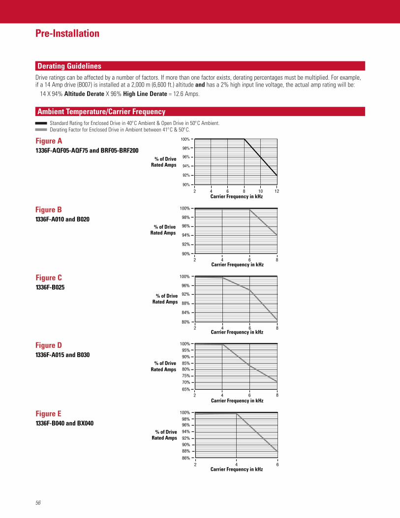
56
Pre-Installation
FeaturesDerating Guidelines
Ambient Temperature/Carrier Frequency
Drive ratings can be affected by a number of factors. If more than one factor exists, derating percentages must be multiplied. For example,if a 14 Amp drive (B007) is installed at a 2,000 m (6,600 ft.) altitude and has a 2% high input line voltage, the actual amp rating will be:
14 X 94% Altitude Derate X 96% High Line Derate = 12.6 Amps.
Carrier Frequency in kHz
% of DriveRated Amps
Figure A 1336F-AQF05-AQF75 and BRF05-BRF200
% of DriveRated Amps
Figure B1336F-A010 and B020
Carrier Frequency in kHz42 6 8
92%
98%
94%
90%
96%
100%
Figure C1336F-B025
Carrier Frequency in kHz42 6 8
84%
96%
88%
80%
92%
100%
% of DriveRated Amps
Figure D1336F-A015 and B030
Carrier Frequency in kHz42 6 8
70%
85%90%95%
75%
65%
80%
100%
% of DriveRated Amps
Figure E1336F-B040 and BX040
Carrier Frequency in kHz2 4 6
88%90%
98%
92%
94%
86%
96%
100%
% of DriveRated Amps
62 4 10 128
92%
98%
94%
90%
96%
100%
Standard Rating for Enclosed Drive in 40º C Ambient & Open Drive in 50º C Ambient.Derating Factor for Enclosed Drive in Ambient between 41º C & 50º C.
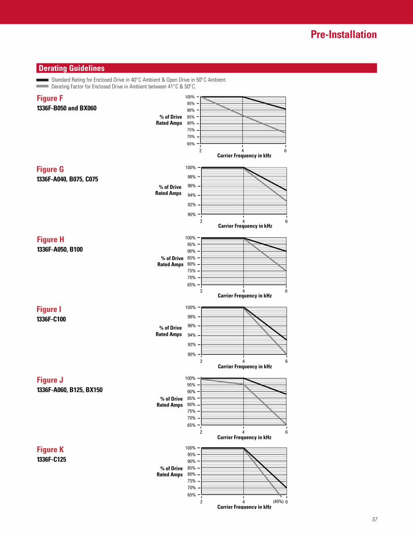
57
Pre-Installation
FeaturesDerating GuidelinesStandard Rating for Enclosed Drive in 40º C Ambient & Open Drive in 50º C Ambient.Derating Factor for Enclosed Drive in Ambient between 41º C & 50º C.
Carrier Frequency in kHz
% of DriveRated Amps
Figure F 1336F-B050 and BX060
% of DriveRated Amps
Figure G1336F-A040, B075, C075
Carrier Frequency in kHz
Figure H1336F-A050, B100
Carrier Frequency in kHz
% of DriveRated Amps
Figure I1336F-C100
Carrier Frequency in kHz
% of DriveRated Amps
Figure J1336F-A060, B125, BX150
Carrier Frequency in kHz
% of DriveRated Amps
Figure K1336F-C125
Carrier Frequency in kHz
% of DriveRated Amps
2 4 6
70%
85%
90%
95%
75%
65%
80%
100%
2 4 6
92%
98%
94%
90%
96%
100%
2 4 6
70%
85%90%95%
75%
65%
80%
100%
2 4 6
92%
98%
94%
90%
96%
100%
2 4 6
70%
85%90%95%
75%
65%
80%
100%
2 4 6
70%
(40%)
85%90%95%
75%
65%
80%
100%
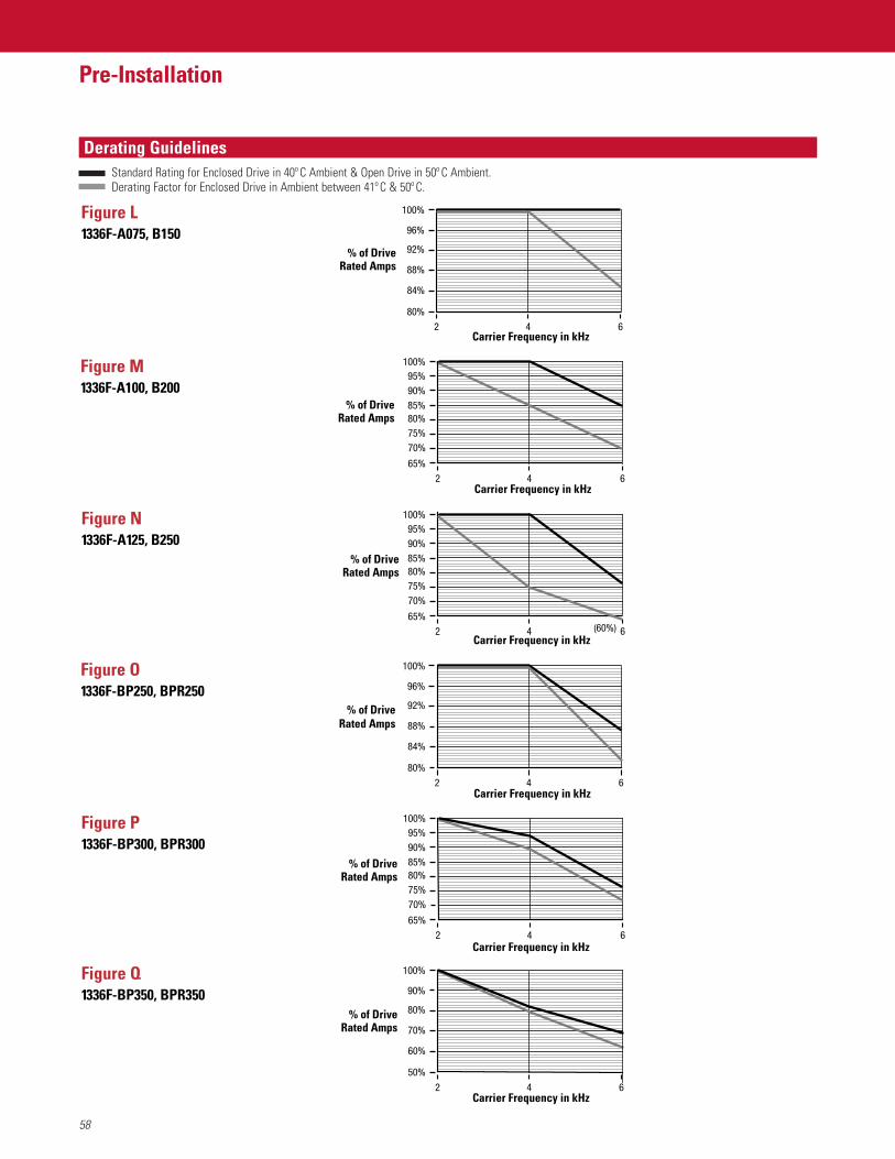
58
Pre-Installation
FeaturesDerating GuidelinesStandard Rating for Enclosed Drive in 40º C Ambient & Open Drive in 50º C Ambient.Derating Factor for Enclosed Drive in Ambient between 41º C & 50º C.
Carrier Frequency in kHz
% of DriveRated Amps
Figure L 1336F-A075, B150
% of DriveRated Amps
Figure M1336F-A100, B200
Carrier Frequency in kHz
Figure N1336F-A125, B250
Carrier Frequency in kHz
% of DriveRated Amps
Figure O1336F-BP250, BPR250
Carrier Frequency in kHz
% of DriveRated Amps
Figure P1336F-BP300, BPR300
Carrier Frequency in kHz
% of DriveRated Amps
Figure Q1336F-BP350, BPR350
Carrier Frequency in kHz
% of DriveRated Amps
42 6
84%
96%
88%
80%
92%
100%
2 4 6
70%
85%90%95%
75%
65%
80%
100%
2 4 6
70%
85%90%95%
75%
65%
80%
100%
(60%)
42 6
84%
96%
88%
80%
92%
100%
2 4 6
70%
85%90%95%
75%
65%
80%
100%
2 4 6
60%
90%
70%
50%
80%
100%
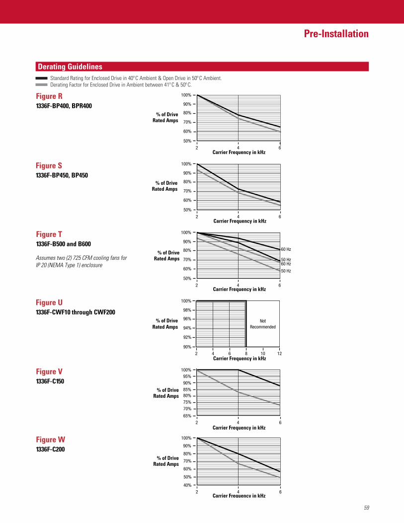
59
Pre-Installation
FeaturesDerating GuidelinesStandard Rating for Enclosed Drive in 40º C Ambient & Open Drive in 50º C Ambient.Derating Factor for Enclosed Drive in Ambient between 41º C & 50º C.
Carrier Frequency in kHz
% of DriveRated Amps
Figure R 1336F-BP400, BPR400
% of DriveRated Amps
Figure S1336F-BP450, BP450
Carrier Frequency in kHz
Figure T1336F-B500 and B600
Carrier Frequency in kHz
% of DriveRated Amps
Figure U1336F-CWF10 through CWF200
Carrier Frequency in kHz
% of DriveRated Amps
Figure V1336F-C150
Carrier Frequency in kHz
% of DriveRated Amps
Figure W1336F-C200
Carrier Frequency in kHz
% of DriveRated Amps
2 4 6
60%
90%
70%
50%
80%
100%
2 4 6
60%
90%
70%
50%
80%
100%
Assumes two (2) 725 CFM cooling fans forIP 20 (NEMA Type 1) enclosure
2 4 6
60%
90%
70%
60 Hz
50 Hz60 Hz
50 Hz
50%
80%
100%
2 4 6
70%
85%90%95%
75%
65%
80%
100%
2 4 6
50%
80%
90%
60%
40%
70%
100%
62 4 10
NotRecommended
128
92%
98%
94%
90%
96%
100%
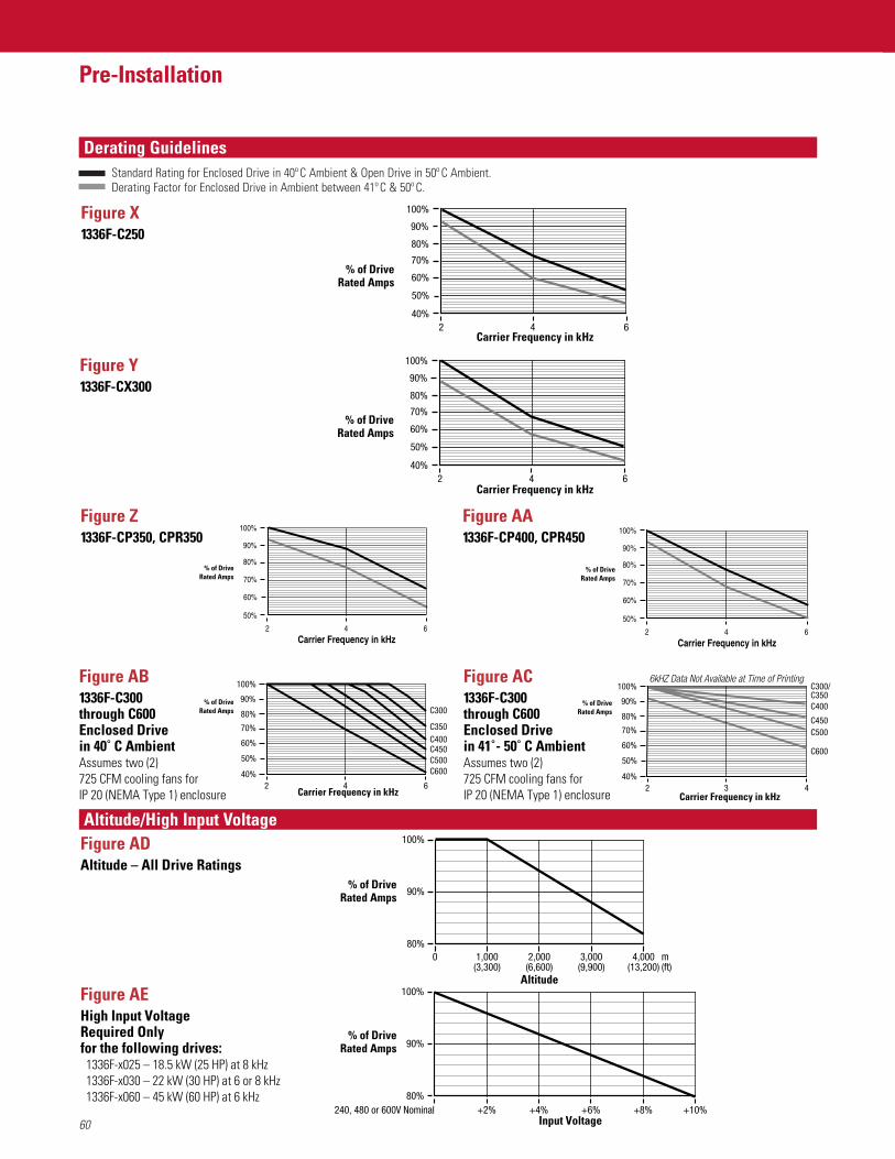
60
Pre-Installation
FeaturesDerating Guidelines
Altitude/High Input Voltage
Standard Rating for Enclosed Drive in 40º C Ambient & Open Drive in 50º C Ambient.Derating Factor for Enclosed Drive in Ambient between 41º C & 50º C.
Carrier Frequency in kHz
% of DriveRated Amps
Figure X 1336F-C250
% of DriveRated Amps
Figure Y1336F-CX300
Carrier Frequency in kHz
Figure AB1336F-C300 through C600Enclosed Drive in 40˚ C AmbientAssumes two (2) 725 CFM cooling fans forIP 20 (NEMA Type 1) enclosure Carrier Frequency in kHz
% of DriveRated Amps
Figure AC1336F-C300 through C600Enclosed Drive in 41˚ - 50˚ C AmbientAssumes two (2) 725 CFM cooling fans forIP 20 (NEMA Type 1) enclosure Carrier Frequency in kHz
% of DriveRated Amps
Figure ADAltitude – All Drive Ratings
% of DriveRated Amps
Figure AEHigh Input VoltageRequired Onlyfor the following drives: 1336F-x025 – 18.5 kW (25 HP) at 8 kHz 1336F-x030 – 22 kW (30 HP) at 6 or 8 kHz 1336F-x060 – 45 kW (60 HP) at 6 kHz
% of DriveRated Amps
2 4 6
50%
80%
90%
60%
40%
70%
100%
2 4 6
50%
80%
90%
60%
40%
70%
100%
2 4 6
50%
80%
90%
60%
40%
70%
100%
C350
C300
C400C450C500C600
Figure Z1336F-CP350, CPR350
% of DriveRated Amps
Figure AA1336F-CP400, CPR450
% of DriveRated Amps
2 3 4
50%
80%
90%
60%
40%
70%
100% C300/C350C400
C450C500
C600
6kHZ Data Not Available at Time of Printing
Altitude
m(ft)
100%
80%
90%
0 4,000(13,200)
3,000(9,900)
2,000(6,600)
1,000(3,300)
Input Voltage
100%
80%
90%
240, 480 or 600V Nominal +6%+4%+2% +10%+8%
Carrier Frequency in kHz2 4 6
60%
90%
70%
50%
80%
100%
Carrier Frequency in kHz2 4 6
60%
90%
70%
50%
80%
100%
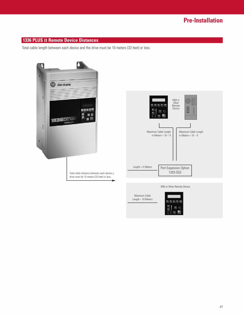
61
Pre-Installation
Features1336 PLUS II Remote Device Distances
Maximum Cable Lengthin Meters = 10 – X
Maximum Cable Lengthin Meters = 10 – X
Length = X Meters
Total cable length between each device and the drive must be 10 meters (33 feet) or less.
Port Expansion Option1203-SG2
HIM orOther
RemoteDevice
Total cable distance between each device &drive must be 10 meters (33 feet) or less.
Maximum CableLength = 10 Meters
HIM or Other Remote Device

62
Pre-Installation
Notes
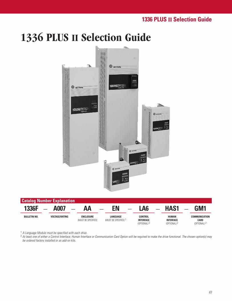
63
1336 PLUS II Selection Guide
Catalog Number Explanation
1336 PLUS II Selection Guide
HAS1HUMAN
INTERFACE(OPTIONAL) 2
LA6CONTROL
INTERFACE(OPTIONAL) 2
ENLANGUAGE
(MUST BE SPECIFIED) 1
1336FBULLETIN NO.
1 A Language Module must be specified with each drive.2 At least one of either a Control Interface, Human Interface or Communication Card Option will be required to make the drive functional. The chosen option(s) may
be ordered factory installed or as add-on kits.
GM1COMMUNICATION
CARD(OPTIONAL) 2
A007VOLTAGE/RATING
AAENCLOSURE
(MUST BE SPECIFIED)
— — — — ——
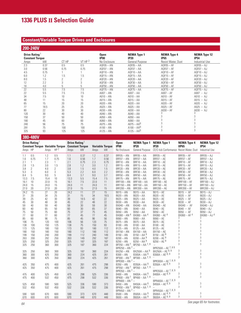
64
1336 PLUS II Selection Guide
FeaturesConstant/Variable Torque Drives and Enclosures
200-240VDrive Rating1 Open NEMA Type 1 NEMA Type 4 NEMA Type 12Constant Torque IP00 IP20 IP65 IP54Amps kW CT HP VT HP 2 No Enclosure General Purpose Resist Water, Dust Industrial Use2.3 0.37 0.5 0.5 AQF05 – AN AQF05 – AA AQF05 – AF AQF05 – AJ3.0 0.56 0.75 0.75 AQF07 – AN AQF07 – AA AQF07 – AF AQF07 – AJ4.5 0.75 1 1 AQF10 – AN AQF10 – AA AQF10 – AF AQF10 – AJ6.0 1.2 1.5 1.5 AQF15 – AN AQF15 – AA AQF15 – AF AQF15 – AJ8.0 1.5 2 2 AQF20 – AN AQF20 – AA AQF20 – AF AQF20 – AJ12 2.2 3 3 AQF30 – AN AQF30 – AA AQF30 – AF AQF30 – AJ18 4.0 5 5 AQF50 – AN AQF50 – AA AQF50 – AF AQF50 – AJ22 5.5 7.5 7.5 AQF75 – AN AQF75 – AA AQF75 – AF AQF75 – AJ22 5.5 7.5 7.5 A007 – AN A007 – AA A007 – AF A007 – AJ34 7.5 10 10 A010 – AN A010 – AA A010 – AF A010 – AJ48 11 15 15 A015 – AN A015 – AA A015 – AF A015 – AJ65 15 20 20 A020 – AN A020 – AA A020 – AF A020 – AJ77 18.5 25 25 A025 – AN A025 – AA A025 – AF A025 – AJ80 22 30 30 A030 – AN A030 – AA A030 – AF A030 – AJ120 30 40 40 A040 – AN A040 – AA 3 3
150 37 50 50 A050 – AN A050 – AA 3 3
180 45 60 60 A060 – AN A060 – AA 3 3
240 56 75 75 A075 – AN A075 – AA9 3 3
291 75 100 100 A100 – AN A100 – AA9 3 3
325 93 125 125 A125 – AN A125 – AA9 3 3
Drive Rating1 Drive Rating1 Open NEMA Type 1 NEMA Type 1 NEMA Type 4 NEMA Type 12Constant Torque Variable Torque Constant Torque Variable Torque IP00 IP20 IP20 IIP65 IP54Amps HP Amps HP 2 Amps kW Amps kW No Enclosure General Purpose CE/C-tick Conformance Resist Water, Dust Industrial Use
1.1 0.5 1.2 0.5 1.1 0.37 1.2 0.37 BRF05 – AN BRF05 – AA BRF05 – AE BRF05 – AF BRF05 – AJ1.6 0.75 1.7 0.75 1.6 0.56 1.7 0.56 BRF07 – AN BRF07 – AA BRF07 – AE BRF07 – AF BRF07 – AJ2.1 1 2.3 1 2.1 0.75 2.3 0.75 BRF10 – AN BRF10 – AA BRF10 – AE BRF10 – AF BRF10 – AJ2.8 1.5 3.0 1.5 2.8 1.2 3.0 1.2 BRF15 – AN BRF15 – AA BRF15 – AE BRF15 – AF BRF15 – AJ3.8 2 4.0 2 3.8 1.5 4.0 1.5 BRF20 – AN BRF20 – AA BRF20 – AE BRF20 – AF BRF20 – AJ5.3 3 6.0 3 5.3 2.2 6.0 2.2 BRF30 – AN BRF30 – AA BRF30 – AE BRF30 – AF BRF30 – AJ8.4 5 9.0 5 8.4 3.7 9.0 3.7 BRF50 – AN BRF50 – AA BRF50 – AE BRF50 – AF BRF50 – AJ13.3 7.5 15.4 10 13.3 5.5 15.4 7.5 BRF75 – AN BRF75 – AA BRF75 – AE BRF75 – AF BRF75 – AJ16.1 10 22.0 15 16.1 7.5 22.0 11 BRF100 – AN BRF100 – AA BRF100 – AE BRF100 – AF BRF100 – AJ24.0 15 24.0 15 24.0 11 24.0 11 BRF150 – AN BRF150 – AA BRF150 – AE BRF150 – AF BRF150 – AJ27.0 20 27.0 20 27.0 15 27.0 15 BRF200 – AN BRF200 – AA BRF200 – AE BRF200 – AF BRF200 – AJ24.2 15 27 20 24.2 11 27 15 B015 – AN B015 – AA B015 – AE B015 – AF B015 – AJ31 20 34 25 31 15 34 18.5 B020 – AN B020 – AA B020 – AE B020 – AF B020 – AJ39 25 42 30 39 18.5 42 22 B025 – AN B025 – AA B025 – AE B025 – AF B025 – AJ45 30 48 30 45 22 48 22 B030 – AN B030 – AA B030 – AE B030 – AF B030 – AJ59 40 59 40 59 30 59 30 BX040 – AN BX040 – AA BX040 – AE BX040 – AF BX040 – AJ60 40 65 50 60 30 65 37 B040 – AN B040 – AA B040 – AE B040 – AF B040 – AJ75 50 75 60 75 37 75 45 B050 – AN B050 – AA B050 – AE B050 – AF B050 – AJ77 60 77 60 77 45 77 45 BX060 – AN 4 BX060 – AA 4 BX060 – AE 4 BX060 – AF 4 BX060 – AJ 485 60 96 75 85 45 96 56 B060 – AN B060 – AA B060 – AE 3 3
106 75 120 100 106 56 120 75 B075 – AN B075 – AA B075 – AE 3 3
138 100 150 125 138 75 150 93 B100 – AN B100 – AA B100 – AE 3 3
173 125 180 150 173 93 180 112 B125 – AN B125 – AA B125 – AE 3 3
180 150 180 150 180 112 180 112 BX150 – AN BX150 – AA BX150 – AE 3 3
199 150 240 200 199 112 240 149 B150 – AN B150 – AA 9 B150 – AE 9 3 3
263 200 292 250 263 149 292 187 B200 – AN B200 – AA 9 B200 – AE 9 3 3
325 250 325 250 325 187 325 187 B250 – AN B250 – AA 9 B250 – AE 9 3 3
325 250 360 300 325 187 360 224 BP250 – AN 7 BP250 – AA 7, 9 – 3 3
BPR250 – AN 7 – BPR250A – AE 7, 8 9
325 250 360 300 325 187 360 224 BX250 – AN BX250A – AA 9 BX250A – AE 8, 9 3 3
360 300 425 350 360 224 425 261 B300 – AN B300A – AA 9 B300A – AE 8, 9 3 3
360 300 425 350 360 224 425 261 BP300 – AN 7 BP300 – AA 7, 9 – 3 3
BPR300 – AN 7 – BPR300A – AE 7, 8, 9
425 350 475 400 425 261 475 298 B350 – AN B350A – AA 9 B350A – AE 8, 9 3 3
425 350 475 400 425 261 475 298 BP350 – AN 7 BP350 – AA 7, 9 – 3 3
BPR350 – AN 7 – BPR350A – AE 7, 8, 9
475 400 525 450 475 298 525 336 B400 – AN B400A – AA 9 B400A – AE 8, 9 3 3
475 400 532 450 475 298 532 336 BP400 – AN 7 BP400 – AA 7, 9 – 3 3
BPR400 – AN 7 – BPR400A – AE 7, 8, 9
525 450 590 500 525 336 590 373 B450 – AN B450A – AA 9 B450A – AE 8, 9 3 3
532 450 532 450 532 336 532 336 BP450 – AN 7 BP450 – AA 7, 9 – 3 3
BPR450 – AN 7 – BPR450A – AE 7, 8, 9
590 500 670 600 590 373 670 448 B500 – AN B500A – AA 9 B500A – AE 8, 9 3 3
670 600 670 600 670 448 670 448 B600 – AN B600A – AA 9 B600A – AE 8, 9 3 3
See page 65 for footnotes.
380-480V
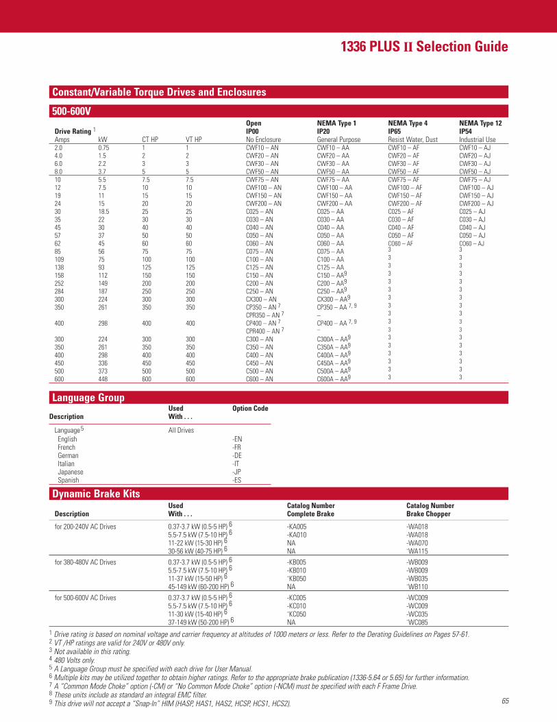
65
1336 PLUS II Selection Guide
Constant/Variable Torque Drives and Enclosures
500-600V
Language Group
Dynamic Brake KitsUsed Catalog Number Catalog Number
Description With . . . Complete Brake Brake Chopper
for 200-240V AC Drives 0.37-3.7 kW (0.5-5 HP) 6 -KA005 -WA0185.5-7.5 kW (7.5-10 HP) 6 -KA010 -WA01811-22 kW (15-30 HP) 6 NA -WA07030-56 kW (40-75 HP) 6 NA -WA115
for 380-480V AC Drives 0.37-3.7 kW (0.5-5 HP) 6 -KB005 -WB0095.5-7.5 kW (7.5-10 HP) 6 -KB010 -WB00911-37 kW (15-50 HP) 6 -KB050 -WB03545-149 kW (60-200 HP) 6 NA -WB110
for 500-600V AC Drives 0.37-3.7 kW (0.5-5 HP) 6 -KC005 -WC0095.5-7.5 kW (7.5-10 HP) 6 -KC010 -WC00911-30 kW (15-40 HP) 6 -KC050 -WC03537-149 kW (50-200 HP) 6 NA -WC085
Used Option Code Description With . . .
Language5 All DrivesEnglish -ENFrench -FRGerman -DEItalian -ITJapanese -JPSpanish -ES
Open NEMA Type 1 NEMA Type 4 NEMA Type 12Drive Rating 1 IP00 IP20 IP65 IP54Amps kW CT HP VT HP No Enclosure General Purpose Resist Water, Dust Industrial Use2.0 0.75 1 1 CWF10 – AN CWF10 – AA CWF10 – AF CWF10 – AJ4.0 1.5 2 2 CWF20 – AN CWF20 – AA CWF20 – AF CWF20 – AJ6.0 2.2 3 3 CWF30 – AN CWF30 – AA CWF30 – AF CWF30 – AJ8.0 3.7 5 5 CWF50 – AN CWF50 – AA CWF50 – AF CWF50 – AJ10 5.5 7.5 7.5 CWF75 – AN CWF75 – AA CWF75 – AF CWF75 – AJ12 7.5 10 10 CWF100 – AN CWF100 – AA CWF100 – AF CWF100 – AJ19 11 15 15 CWF150 – AN CWF150 – AA CWF150 – AF CWF150 – AJ24 15 20 20 CWF200 – AN CWF200 – AA CWF200 – AF CWF200 – AJ30 18.5 25 25 C025 – AN C025 – AA C025 – AF C025 – AJ35 22 30 30 C030 – AN C030 – AA C030 – AF C030 – AJ45 30 40 40 C040 – AN C040 – AA C040 – AF C040 – AJ57 37 50 50 C050 – AN C050 – AA C050 – AF C050 – AJ62 45 60 60 C060 – AN C060 – AA CO60 – AF CO60 – AJ85 56 75 75 C075 – AN C075 – AA 3 3
109 75 100 100 C100 – AN C100 – AA 3 3
138 93 125 125 C125 – AN C125 – AA 3 3
158 112 150 150 C150 – AN C150 – AA9 3 3
252 149 200 200 C200 – AN C200 – AA9 3 3
284 187 250 250 C250 – AN C250 – AA9 3 3
300 224 300 300 CX300 – AN CX300 – AA9 3 3
350 261 350 350 CP350 – AN 7 CP350 – AA 7, 9 3 3
CPR350 – AN 7 – 3 3
400 298 400 400 CP400 – AN 7 CP400 – AA 7, 9 3 3
CPR400 – AN 7 – 3 3
300 224 300 300 C300 – AN C300A – AA9 3 3
350 261 350 350 C350 – AN C350A – AA9 3 3
400 298 400 400 C400 – AN C400A – AA9 3 3
450 336 450 450 C450 – AN C450A – AA9 3 3
500 373 500 500 C500 – AN C500A – AA9 3 3
600 448 600 600 C600 – AN C600A – AA9 3 3
1 Drive rating is based on nominal voltage and carrier frequency at altitudes of 1000 meters or less. Refer to the Derating Guidelines on Pages 57-61.2 VT /HP ratings are valid for 240V or 480V only.3 Not available in this rating.4 480 Volts only.5 A Language Group must be specified with each drive for User Manual.6 Multiple kits may be utilized together to obtain higher ratings. Refer to the appropriate brake publication (1336-5.64 or 5.65) for further information.7 A “Common Mode Choke” option (-CM) or “No Common Mode Choke” option (-NCM) must be specified with each F Frame Drive.8 These units include as standard an integral EMC filter.9 This drive will not accept a “Snap-In” HIM (HASP, HAS1, HAS2, HCSP, HCS1, HCS2).
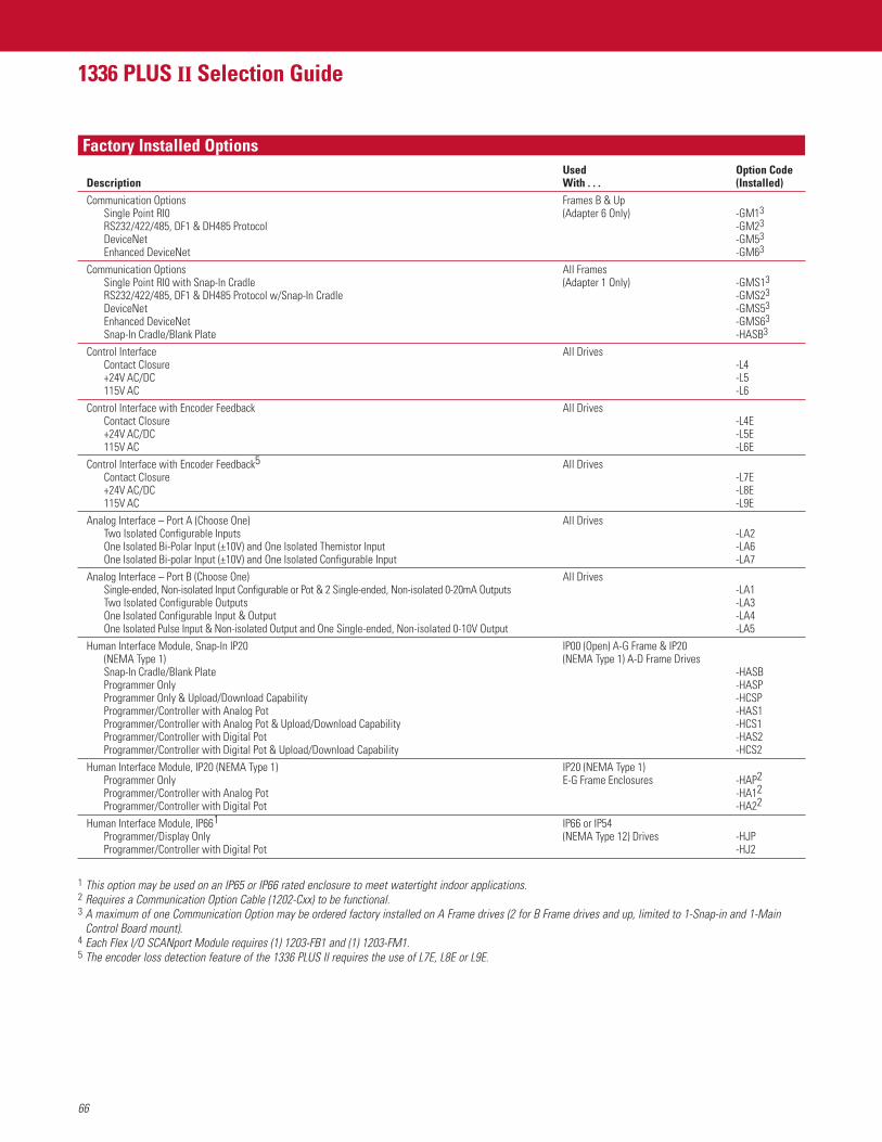
66
1336 PLUS II Selection Guide
Factory Installed OptionsUsed Option Code
Description With . . . (Installed)Communication Options Frames B & Up
Single Point RI0 (Adapter 6 Only) -GM13
RS232/422/485, DF1 & DH485 Protocol -GM23
DeviceNet -GM53
Enhanced DeviceNet -GM63
Communication Options All FramesSingle Point RI0 with Snap-In Cradle (Adapter 1 Only) -GMS13
RS232/422/485, DF1 & DH485 Protocol w/Snap-In Cradle -GMS23
DeviceNet -GMS53
Enhanced DeviceNet -GMS63
Snap-In Cradle/Blank Plate -HASB3
Control Interface All DrivesContact Closure -L4+24V AC/DC -L5115V AC -L6
Control Interface with Encoder Feedback All DrivesContact Closure -L4E+24V AC/DC -L5E115V AC -L6E
Control Interface with Encoder Feedback5 All DrivesContact Closure -L7E+24V AC/DC -L8E115V AC -L9E
Analog Interface – Port A (Choose One) All DrivesTwo Isolated Configurable Inputs -LA2One Isolated Bi-Polar Input (±10V) and One Isolated Themistor Input -LA6One Isolated Bi-polar Input (±10V) and One Isolated Configurable Input -LA7
Analog Interface – Port B (Choose One) All DrivesSingle-ended, Non-isolated Input Configurable or Pot & 2 Single-ended, Non-isolated 0-20mA Outputs -LA1Two Isolated Configurable Outputs -LA3One Isolated Configurable Input & Output -LA4One Isolated Pulse Input & Non-isolated Output and One Single-ended, Non-isolated 0-10V Output -LA5
Human Interface Module, Snap-In IP20 IP00 (Open) A-G Frame & IP20(NEMA Type 1) (NEMA Type 1) A-D Frame DrivesSnap-In Cradle/Blank Plate -HASBProgrammer Only -HASPProgrammer Only & Upload/Download Capability -HCSPProgrammer/Controller with Analog Pot -HAS1Programmer/Controller with Analog Pot & Upload/Download Capability -HCS1Programmer/Controller with Digital Pot -HAS2Programmer/Controller with Digital Pot & Upload/Download Capability -HCS2
Human Interface Module, IP20 (NEMA Type 1) IP20 (NEMA Type 1)Programmer Only E-G Frame Enclosures -HAP2Programmer/Controller with Analog Pot -HA12Programmer/Controller with Digital Pot -HA22
Human Interface Module, IP661 IP66 or IP54 Programmer/Display Only (NEMA Type 12) Drives -HJPProgrammer/Controller with Digital Pot -HJ2
1 This option may be used on an IP65 or IP66 rated enclosure to meet watertight indoor applications.2 Requires a Communication Option Cable (1202-Cxx) to be functional.3 A maximum of one Communication Option may be ordered factory installed on A Frame drives (2 for B Frame drives and up, limited to 1-Snap-in and 1-Main
Control Board mount).4 Each Flex I/O SCANport Module requires (1) 1203-FB1 and (1) 1203-FM1.5 The encoder loss detection feature of the 1336 PLUS II requires the use of L7E, L8E or L9E.
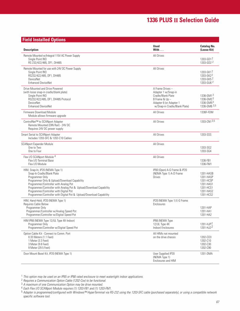
67
1336 PLUS II Selection Guide
Field Installed OptionsUsed Catalog No.
Description With . . . (Loose Kit)
Remote Mounted w/Integral 115V AC Power Supply All DrivesSingle Point RIO 1203-GD12
RS 232/422/485, DF1, DH485 1203-GD2 2
Remote Mounted for use with 24V DC Power Supply All DrivesSingle Point RIO 1203-GK12
RS232/422/485, DF1, DH485 1203-GK22
DeviceNet 1203-GK5 2
Enhanced DeviceNet 1203-GU6 2
Drive Mounted and Drive Powered A Frame Drives –(with loose snap-in cradle/blank plate) Adapter 1 w/Snap-in
Single Point RIO Cradle/Blank Plate 1336-GM13
RS232/422/485, DF1, DH485 Protocol B Frame & Up – 1336-GM23
DeviceNet Adapter 6 (or Adapter 1 1336-GM53
Enhanced DeviceNet w/Snap-in Cradle/Blank Plate) 1336-GM6 3,5
Firmware Download Module All Drives 1336F-FDMModule allows firmware upgrade
ControlNet™ to SCANport Adapter All Drives 1203-CN13,5
Remote Mounted (DIN Rail) - 24V DCRequires 24V DC power supply
Smart Serial to SCANport Adapter All Drives 1203-SSSIncludes 1203-SFC & 1202-C10 Cables
SCANport Expander Module All DrivesOne to Two 1203-SG2One to Four 1203-SG4
Flex I/O SCANport Module 4 All DrivesFlex I/O Terminal Base 1336-FB1Flex I/O Module 1336-FM1
HIM, Snap-In, IP20 (NEMA Type 1) IP00 (Open) A-G Frame & IP20Snap-In Cradle/Blank Plate (NEMA Type 1) A-D Frame 1201-HASBProgrammer Only Drives 1201-HASPProgrammer Only & Upload/Download Capability 1201-HCSPProgrammer/Controller with Analog Pot 1201-HAS1Programmer/Controller with Analog Pot & Upload/Download Capability 1201-HCS1Programmer/Controller with Digital Pot 1201-HAS2Programmer/Controller with Digital Pot & Upload/Download Capability 1201-HCS2
HIM, Hand-Held, IP20 (NEMA Type 1) IP20 (NEMA Type 1) E-G FrameRequires Cable Below Enclosures
Programmer Only 1201-HAPProgrammer/Controller w/Analog Speed Pot 1201-HA1Programmer/Controller w/Digital Speed Pot 1201-HA2
HIM IP66 (NEMA Type 12/UL Type 4X-Indoor) IP66 (NEMA TypeProgrammer Only 12/UL Type 4X 1201-HJP2
Programmer/Controller w/Digital Speed Pot Indoor) Enclosures 1201-HJ22
Option Cable Kit - Connect to Comm. Port All HIMs not mounted0.33 Meters (1.1 Feet) on the drive chassis 1202-CO31 Meter (3.3 Feet) 1202-C103 Meter (9.8 Feet) 1202-C309 Meter (29.5 Feet) 1202-C90
Door Mount Bezel Kit, IP20 (NEMA Type 1) User Supplied IP20 1201-DMA(NEMA Type 1)Enclosures and HIM
1 This option may be used on an IP65 or IP66 rated enclosure to meet watertight indoor applications.2 Requires a Communication Option Cable (1202-Cxx) to be functional.3 A maximum of one Communication Option may be drive mounted.4 Each Flex I/O SCANport Module requires (1) 1203-FB1 and (1) 1203-FM1.5 Adapter is programmed/configured with Windows™ HyperTerminal via RS-232 using the 1203-SFC cable (purchased separately), or using a compatible network
specific software tool.

68
1336 PLUS II Selection Guide
Notes
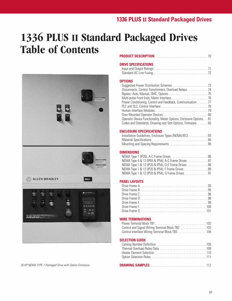
69
1336 PLUS II Standard Packaged Drives
1336 PLUS II Standard Packaged DrivesTable of Contents
30 HP NEMA TYPE 1 Packaged Drive with Option Enclosure
PRODUCT DESCRIPTION . . . . . . . . . . . . . . . . . . . . . . . . . . . . . . . . . 70
DRIVE SPECIFICATIONSInput and Output Ratings. . . . . . . . . . . . . . . . . . . . . . . . . . . . . . . . . . 71Standard AC Line Fusing . . . . . . . . . . . . . . . . . . . . . . . . . . . . . . . . . . 72
OPTIONSSuggested Power Distribution Schemes . . . . . . . . . . . . . . . . . . . . . . 73Disconnects, Control Transformers, Overload Relays. . . . . . . . . . . . . 74Bypass- Auto, Manual, SMC, Options. . . . . . . . . . . . . . . . . . . . . . . . . 75Multi-pulse Front Ends, Motor Interface. . . . . . . . . . . . . . . . . . . . . . . 76Power Conditioning, Control and Feedback, Communication. . . . . . . 77PLC and SLC, Control Interface . . . . . . . . . . . . . . . . . . . . . . . . . . . . . 78Human Interface Modules . . . . . . . . . . . . . . . . . . . . . . . . . . . . . . . . . 79Door Mounted Operator Devices . . . . . . . . . . . . . . . . . . . . . . . . . . . . 80Operator Device Functionality, Meter Options, Enclosure Options. . . 81Codes and Standards, Drawing and Test Options, Firmware . . . . . . . 82
ENCLOSURE SPECIFICATIONSInstallation Guidelines, Enclosure Types (NEMA/IEC) . . . . . . . . . . . . 83Material Specifications . . . . . . . . . . . . . . . . . . . . . . . . . . . . . . . . . . . 84Mounting and Spacing Requirements . . . . . . . . . . . . . . . . . . . . . . . . 85
DIMENSIONSNEMA Type 1 (IP20), A-C Frame Drives . . . . . . . . . . . . . . . . . . . . . . . 86NEMA Type 4 & 12 (IP65 & IP54), A-C Frame Drives . . . . . . . . . . . . . 87NEMA Type 1 & 12 (IP20 & IP54), D-E Frame Drives . . . . . . . . . . . . . 88NEMA Type 1 & 12 (IP20 & IP54), F Frame Drives . . . . . . . . . . . . . . . 89NEMA Type 1 & 12 (IP20 & IP54), G Frame Drives. . . . . . . . . . . . . . . 91
PANEL LAYOUTSDrive Frame A . . . . . . . . . . . . . . . . . . . . . . . . . . . . . . . . . . . . . . . . . . 93Drive Frame B . . . . . . . . . . . . . . . . . . . . . . . . . . . . . . . . . . . . . . . . . . 95Drive Frame C . . . . . . . . . . . . . . . . . . . . . . . . . . . . . . . . . . . . . . . . . . 96Drive Frame D . . . . . . . . . . . . . . . . . . . . . . . . . . . . . . . . . . . . . . . . . . 98Drive Frame E . . . . . . . . . . . . . . . . . . . . . . . . . . . . . . . . . . . . . . . . . . 99Drive Frame F. . . . . . . . . . . . . . . . . . . . . . . . . . . . . . . . . . . . . . . . . . 100Drive Frame G . . . . . . . . . . . . . . . . . . . . . . . . . . . . . . . . . . . . . . . . . 101
WIRE TERMINATIONSPower Terminal Block TB1 . . . . . . . . . . . . . . . . . . . . . . . . . . . . . . . . 102Control and Signal Wiring Terminal Block TB2 . . . . . . . . . . . . . . . . 103Control Interface Wiring Terminal Block TB3 . . . . . . . . . . . . . . . . . . 104
SELECTION GUIDECatalog Number Definition . . . . . . . . . . . . . . . . . . . . . . . . . . . . . . . 105Thermal Overload Relay Data . . . . . . . . . . . . . . . . . . . . . . . . . . . . . 109Heater Element Selection . . . . . . . . . . . . . . . . . . . . . . . . . . . . . . . . 110Option Selection Rules . . . . . . . . . . . . . . . . . . . . . . . . . . . . . . . . . . 111
DRAWING SAMPLES . . . . . . . . . . . . . . . . . . . . . . . . . . . . . . . . . . . 112
General Specifications
70
Product Description
Drive Specifications
The 1336 PLUS II Standard Packaged Drive Package
In most cases the general specifications of a standard packaged drive will match those of a stand-alone drive, refer to pages 18 and 19.Some items such as Agency Certification and Maximum Short Circuit Protection will be specific to the options chosen.
Agency Certification Refer to the Codes and Standards in the Options section
Maximum Short Circuit Drive Package The short circuit interrupt capability of any standard packaged drive will be based upon the specific(Current Rating) combination of power options chosen
The heart of every standard packaged drive is a 1336 PLUS II variable frequency controller.The packaged drives program provides 1336 PLUS II drives assembled with a much larger offering of factory mounted options than what isnormally available with a standard product.Ratings are provides for 0.37-93 kW (0.5-125 HP) at 230V, 0.37-448 kW (0.5-600 HP) at 460V, or 0.75-448 kW (1-600 HP) at 575V. Separateconstant torque and variable torque ratings are available for 460V applications.
PackagingRemovable common Human Interface Module.Provides simplicity of programming and flexibility of operation.Thermal dissipation management.Design and extensive infra-red testing minimizes hot spots to maximize reliability.Modular enclosure.Design to accommodate a wide variety of drive ratings and option combinations.IP 20, IP65 & IP54 (NEMA Type 1, 4 & 12) configurations.Accommodated with “heat sink through the back” design wherever possible.
StandardizationPre-defined to reduce cost and time.By using pre-defined, and in most cases pre-engineered, options standardization provides consistency of product offering, resulting inreduced costs, shorter delivery time, and ease of product installation. Even in the case of custom designed drive packages, generally 80%of the engineering already exists.
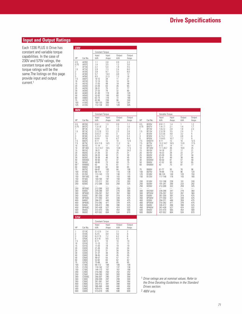
71
Drive Specifications
Input and Output Ratings
1 Drive ratings are at nominal values. Refer tothe Drive Derating Guidelines in the StandardDrives section.
2 480V only.
230VConstant TorqueInput Input Output Output
HP Cat No. kVA Amps kVA Amps
0.5 AF05C 1.1 2.8 0.9 2.30.75 AF07C 1.4 3.5 1.2 3.01 AF10C 2.2 5.4 1.8 4.51.5 AF15C 2.9 7.3 2.4 6.02 AF20C 3.9 9.7 3.2 8.03 AF30C 5.7 14.3 4.8 125 AF50C 8.5 21.3 7.2 187.5 A007C 10-12 28 11 2710 A010C 12-14 35 14 3415 A015C 17-20 49 19 4820 A020C 22-26 63 26 6525 A025C 26-31 75 31 7730 A030C 27-33 79 32 8040 A040C 41-49 119 48 12050 A050C 52-62 149 60 15060 A060C 62-74 178 72 18075 A075C 82-99 238 96 240100 A100C 100-120 289 116 291125 A125C 112-134 322 129 325
460VConstant Torque Variable TorqueInput Input Output Output Input Input Output Output
HP Cat No. kVA Amps kVA Amps HP Cat No. kVA Amps kVA Amps
0.5 BFO5C 0.9-1 1.3 0.9 1.1 0.5 BF05V 0.9-1.1 1.4 1 1.20.75 BFO7C 1.3-1.6 2 1.3 1.6 0.75 BF07V 1.4-1.7 2.1 1.4 1.71 BF10C 1.6-2 2.8 1.6 2.1 1 BF10V 1.8-2.2 2.8 1.8 2.31.5 BF15C 2.2-2.6 3.3 2.2 2.8 1.5 BF15V 2.3-2.8 3.5 2.4 32 BF20C 3.0-3.7 4.6 3 3.8 2 BF20V 3.2-3.8 4.8 3.2 43 BF30C 4.2-5.1 6.4 4.2 5.3 3 BF30V 4.7-5.7 7.2 4.8 65 BF50C 6.6-8 10 6.7 8.4 5 BF50V 7.0-8.5 10.7 7.2 97.5 B007C 8-11 13 10 12.5 7.5 BX007V 8-11 13 10 12.57.5 BF75C 9.5-11.6 14.5 11.2 14 7.5 BF75V 12.2-14.7 18.5 13.9 17.510 B010C 11-14 17 13 16.1 10 B007V 9-12 14 11 1410 BF100C 12.2-14.7 18.5 13.9 17.5 10 BF100V 17.1-20.7 26 19.9 2515 B015C 16-21 25 19 24.2 15 B010V 14-18 22 17 2120 B020C 21-26 32 25 31 20 B015V 18-23 28 22 2725 B025C 26-33 40 31 39 25 B020V 23-29 35 27 3430 B030C 30-38 46 36 45 30 B030V 32-41 49 38 4840 BX040C 40-50 61 47 59 40 BX040V 40-50 61 47 5950 B050C 48-60 73 60 75 50 B040V 41-52 63 52 6560 2 BX060C 62 75 61 77 60 BX060V 62 75 61 7760 B060C 54-68 82 68 8575 B075C 69-87 105 84 106 75 B060V 61-77 93 76 96100 B100C 90-114 137 110 138 100 B075V 78-99 119 96 120125 B125C 113-143 172 138 173 125 B100V 98-124 149 120 150150 BX150C 148 178 143 180 150 B125V 117-148 178 143 180150 B150C 130-164 197 159 199200 B200C 172-217 261 210 263 200 B150V 157-198 238 191 240250 B250C 212-268 322 259 325 250 B200V 191-241 290 233 292— — — — — — 250 B250V 212-268 322 259 325250 BP250C 212-268 322 259 325 — — — — — —300 B300C 228-288 347 279 360 300 BX250V 228-288 347 279 360300 BP300C 235-297 357 287 360 300 BP250V 235-297 357 287 360350 B350C 261-330 397 319 425 350 B300V 261-330 397 319 425350 BP350C 277-350 421 339 425 350 BP300V 277-350 421 339 425400 B400C 294-371 446 359 475 400 B350V 294-371 446 359 475400 BP400C 310-392 471 378 475 400 BP350V 310-392 471 378 475450 B450C 326-412 496 398 525 450 B400V 326-412 496 398 525450 BP450C 347-438 527 424 532 450 BP400V 347-438 527 424 532500 B500C 372-470 565 454 590 500 B450V 372-470 565 454 590600 B600C 437-552 664 534 670 600 B500V 437-552 664 534 670
575VConstant TorqueInput Input Output Output
HP Cat No. kVA Amps kVA Amps
1 CF10C 2.1-2.5 2.4 2.1 22 CF20C 4.2-5 4.8 4.2 43 CF30C 6.2-7.5 7.2 6.2 65 CF50C 8.3-10 9.6 8.3 87.5 C007C 9-11 10 10 1010 C010C 11-13 12 12 1215 C015C 17-20 19 19 1920 C020C 21-26 25 24 2425 C025C 27-32 31 30 3030 C030C 31-37 36 35 3540 C040C 38-45 44 45 4550 C050C 48-57 55 57 5760 C060C 52-62 60 62 6275 C075C 73-88 84 85 85100 C100C 94-112 108 109 109125 C125C 118-142 137 137 138150 C150C 144-173 167 167 168200 C200C 216-260 250 252 252250 C250C 244-293 282 283 384300 CX300C 256-307 295 297 300300 C300C 258-309 297 299 300350 C350C 301-361 347 349 350400 C400C 343-412 397 398 400450 C450C 386-464 446 448 450500 C500C 429-515 496 498 500600 C600C 515-618 595 598 600
Each 1336 PLUS II Drive hasconstant and variable torquecapabilities. In the case of230V and 575V ratings, theconstant torque and variabletorque ratings will be thesame.The listings on this pageprovide input and outputcurrent.1
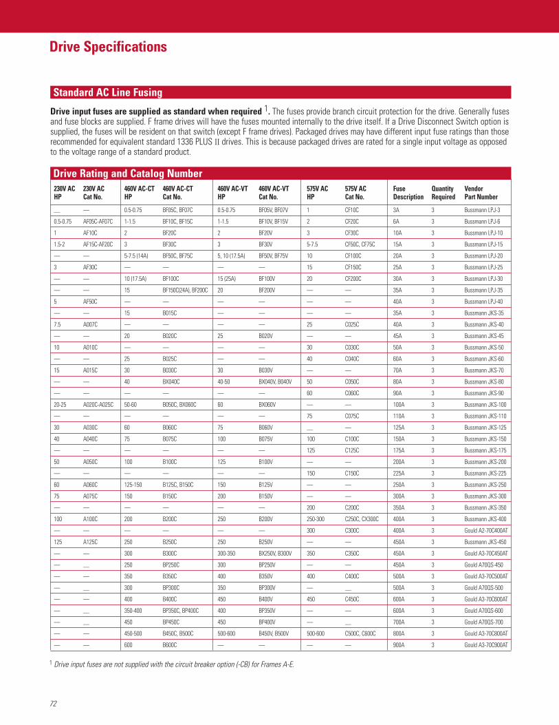
Standard AC Line Fusing
Drive Rating and Catalog Number
72
Drive Specifications
230V AC 230V AC 460V AC-CT 460V AC-CT 460V AC-VT 460V AC-VT 575V AC 575V AC Fuse Quantity VendorHP Cat No. HP Cat No. HP Cat No. HP Cat No. Description Required Part Number
— — 0.5-0.75 BF05C, BF07C 0.5-0.75 BF05V, BF07V 1 CF10C 3A 3 Bussmann LPJ-3
0.5-0.75 AF05C-AF07C 1-1.5 BF10C, BF15C 1-1.5 BF10V, BF15V 2 CF20C 6A 3 Bussmann LPJ-6
1 AF10C 2 BF20C 2 BF20V 3 CF30C 10A 3 Bussmann LPJ-10
1.5-2 AF15C-AF20C 3 BF30C 3 BF30V 5-7.5 CF50C, CF75C 15A 3 Bussmann LPJ-15
— — 5-7.5 (14A) BF50C, BF75C 5, 10 (17.5A) BF50V, BF75V 10 CF100C 20A 3 Bussmann LPJ-20
3 AF30C — — — — 15 CF150C 25A 3 Bussmann LPJ-25
— — 10 (17.5A) BF100C 15 (25A) BF100V 20 CF200C 30A 3 Bussmann LPJ-30
— — 15 BF150C(24A), BF200C 20 BF200V — — 35A 3 Bussmann LPJ-35
5 AF50C — — — — — — 40A 3 Bussmann LPJ-40
— — 15 B015C — — — — 35A 3 Bussmann JKS-35
7.5 A007C — — — — 25 C025C 40A 3 Bussmann JKS-40
— — 20 B020C 25 B020V — — 45A 3 Bussmann JKS-45
10 A010C — — — — 30 C030C 50A 3 Bussmann JKS-50
— — 25 B025C — — 40 C040C 60A 3 Bussmann JKS-60
15 A015C 30 B030C 30 B030V — — 70A 3 Bussmann JKS-70
— — 40 BX040C 40-50 BX040V, B040V 50 C050C 80A 3 Bussmann JKS-80
— — — — — — 60 C060C 90A 3 Bussmann JKS-90
20-25 A020C-A025C 50-60 B050C, BX060C 60 BX060V — — 100A 3 Bussmann JKS-100
— — — — — — 75 C075C 110A 3 Bussmann JKS-110
30 A030C 60 B060C 75 B060V — — 125A 3 Bussmann JKS-125
40 A040C 75 B075C 100 B075V 100 C100C 150A 3 Bussmann JKS-150
— — — — — — 125 C125C 175A 3 Bussmann JKS-175
50 A050C 100 B100C 125 B100V — — 200A 3 Bussmann JKS-200
— — — — — — 150 C150C 225A 3 Bussmann JKS-225
60 A060C 125-150 B125C, B150C 150 B125V — — 250A 3 Bussmann JKS-250
75 A075C 150 B150C 200 B150V — — 300A 3 Bussmann JKS-300
— — — — — — 200 C200C 350A 3 Bussmann JKS-350
100 A100C 200 B200C 250 B200V 250-300 C250C, CX300C 400A 3 Bussmann JKS-400
— — — — — — 300 C300C 400A 3 Gould A2-70C400AT
125 A125C 250 B250C 250 B250V — — 450A 3 Bussmann JKS-450
— — 300 B300C 300-350 BX250V, B300V 350 C350C 450A 3 Gould A3-70C450AT
— — 250 BP250C 300 BP250V — — 450A 3 Gould A70QS-450
— — 350 B350C 400 B350V 400 C400C 500A 3 Gould A3-70C500AT
— — 300 BP300C 350 BP300V — — 500A 3 Gould A70QS-500
— — 400 B400C 450 B400V 450 C450C 600A 3 Gould A3-70C600AT
— — 350-400 BP350C, BP400C 400 BP350V — — 600A 3 Gould A70QS-600
— — 450 BP450C 450 BP400V — — 700A 3 Gould A70QS-700
— — 450-500 B450C, B500C 500-600 B450V, B500V 500-600 C500C, C600C 800A 3 Gould A3-70C800AT
— — 600 B600C — — — — 900A 3 Gould A3-70C900AT
Drive input fuses are supplied as standard when required 1. The fuses provide branch circuit protection for the drive. Generally fusesand fuse blocks are supplied. F frame drives will have the fuses mounted internally to the drive itself. If a Drive Disconnect Switch option issupplied, the fuses will be resident on that switch (except F frame drives). Packaged drives may have different input fuse ratings than thoserecommended for equivalent standard 1336 PLUS II drives. This is because packaged drives are rated for a single input voltage as opposedto the voltage range of a standard product.
1 Drive input fuses are not supplied with the circuit breaker option (-CB) for Frames A-E.
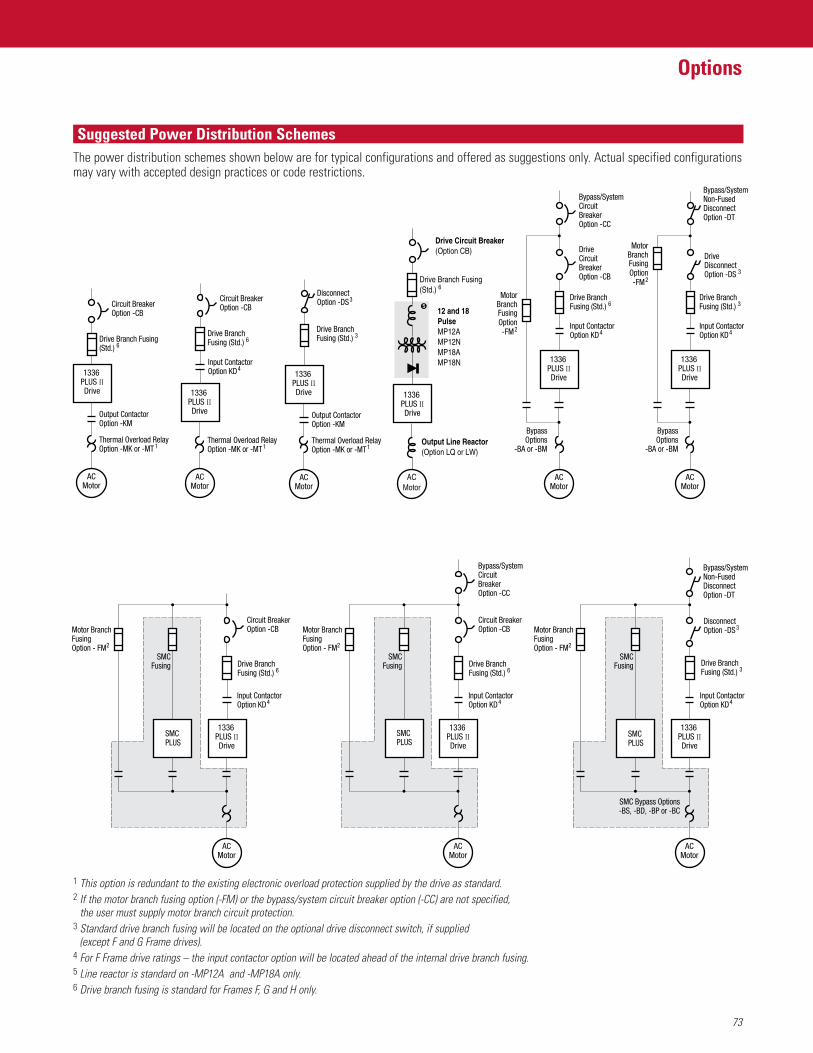
73
Options
Suggested Power Distribution Schemes
Drive Branch Fusing(Std.) 6
Circuit BreakerOption -CB
Circuit BreakerOption -CB
1336 PLUS IIDrive
1336 PLUS IIDrive
1336 PLUS IIDrive
ACMotor
Output ContactorOption -KM
Thermal Overload RelayOption -MK or -MT 1
Bypass/SystemCircuit BreakerOption -CC
DriveCircuit BreakerOption -CB
Bypass/SystemCircuit BreakerOption -CC
Input ContactorOption KD4
Input ContactorOption KD4
Drive Branch Fusing (Std.) 3
Drive Branch Fusing (Std.) 3
DriveDisconnect Option -DS 3
Disconnect Option -DS3Motor Branch
FusingOption - FM2
Bypass/SystemNon-FusedDisconnectOption -DT
Bypass/SystemNon-FusedDisconnectOption -DT
BypassOptions
-BA or -BM
ACMotor
MotorBranch FusingOption-FM2
1336 PLUS IIDrive
Input ContactorOption KD4
Drive Branch Fusing (Std.) 6
BypassOptions
-BA or -BM
SMC Bypass Options-BS, -BD, -BP or -BC
SMC Bypass Options-BS, -BD, -BP or -BC
ACMotor
MotorBranch FusingOption-FM2
Motor BranchFusingOption - FM2
Drive BranchFusing (Std.) 6
SMCFusing
ACMotor
SMC PLUS
Circuit BreakerOption -CB
1336 PLUS IIDrive
Input ContactorOption KD4
Drive BranchFusing (Std.) 6
SMCFusing
Motor BranchFusingOption - FM2
ACMotor
SMC PLUS
SMC Bypass Options-BS, -BD, -BP or -BC
1336 PLUS IIDrive
Input ContactorOption KD4
SMCFusing
ACMotor
SMC PLUS
1336 PLUS IIDrive
ACMotor
12 and 18PulseMP12AMP12NMP18AMP18N
Drive Branch Fusing(Std.) 6
Output Line Reactor(Option LQ or LW)
Drive Circuit Breaker(Option CB)
5
1336 PLUS IIDrive
Drive BranchFusing (Std.) 6
Circuit BreakerOption -CB
Input ContactorOption KD4
ACMotor
Thermal Overload RelayOption -MK or -MT1
1336 PLUS IIDrive
Drive Branch Fusing (Std.) 3
Disconnect Option -DS3
ACMotor
Output ContactorOption -KM
Thermal Overload RelayOption -MK or -MT1
The power distribution schemes shown below are for typical configurations and offered as suggestions only. Actual specified configurationsmay vary with accepted design practices or code restrictions.
1 This option is redundant to the existing electronic overload protection supplied by the drive as standard.2 If the motor branch fusing option (-FM) or the bypass/system circuit breaker option (-CC) are not specified,
the user must supply motor branch circuit protection.3 Standard drive branch fusing will be located on the optional drive disconnect switch, if supplied
(except F and G Frame drives).4 For F Frame drive ratings – the input contactor option will be located ahead of the internal drive branch fusing.5 Line reactor is standard on -MP12A and -MP18A only.6 Drive branch fusing is standard for Frames F, G and H only.
Power Disconnect Options
74
Options
Drive Input Fuses This is a standard feature of all packaged drive assemblies except for frames A-E with the circuit (Standard) breaker option (-CB). These fuses provide branch circuit protection in the drive mode of operation. If a
bypass option is included, then separate branch circuit protection may be supplied by the customer or byspecifying option -FM. Refer to AC Line Fusing in the Drive Specifications section for specific fuse ratinginformation.
Drive Circuit Breaker This option provides branch circuit protection for frames A-E and is for disconnecting power only for (Option CB) frames F, G & H. Standard drive input fuses (see above) supply branch circuit protection for frames F, G &
H. Most ratings will utilize a motor circuit protector (MCP) type breaker. Where MCP’s are not available amolded case switch will be provided. All switches include handle operators, door interlocking and arepadlockable. Thermal magnetic type breakers are not required since this type of protection is alreadysupplied in the drive.
Drive Disconnect Switch An Allen-Bradley Bulletin 194R rotary switch is provided on A-C frame drives. A flange mount or rotary(Option DS) style switch (1494 F where possible) is provided on D frame drives and larger. With the exception of the F
frame drive, the drive input fuses will be resident on the switch, allowing it to meet the requirements forbranch circuit protection. All disconnect switches are door interlocked and padlockable.
Drive Input Contactor An Allen-Bradley Bulletin 100 contactor (where available) is provided between the AC line and the drive.(Option KD) The contactor will close on power up using A-B circuitry, or may be alternately controlled by customer
supplied remote contact closure logic.
Drive Output Contactor An Allen-Bradley Bulletin 100 contactor (where available) is provided between the drive output (Option KM) and the motor. The contactor will close on power up, and open after a drive fault or loss of power.
Drive Only Control Power Provides a control power transformer mounted and wired inside the drive enclosure. The transformer(Option CF) is rated for drive and options power only. There is no additional capacity for customer use.
Drive Plus 250VA Control Power This option provides a control power transformer mounted and wired inside the drive enclosure. The(Option CP) transformer is rated for drive power plus an additional 250VA at 120V AC for customer use.
Drive Plus 500VA Control Power This option provides a control power transformer mounted and wired inside the drive enclosure. The(Option CT) transformer is rated for drive power plus an additional 500VA at 120V AC for customer use.
Class 10 Motor Thermal Overload Relay This option provides an Allen-Bradley Bulletin 193 bi-metallic thermal overload relay. The 193 contains(Option MT) an integral heater element with an adjustable trip setting – refer to Motor Thermal Overload Relay
Selection in the Selection Guide section. No additional heater elements are required. A Class 10 overloadrelay will trip in 10 seconds or less at 600% of motor current setting. The motor overload protectionprovided by this option is redundant to the electronic overload protection provided by the drive itself.
Class 20 Motor Thermal Overload Relay This option provides an Allen-Bradley Bulletin 592 thermal overload relay. The Bulletin 592 contains(Option MK) a manual reset and requires a eutectic alloy heater element – refer to Heater Element Selection in the
Selection Guide section. The heater element is not supplied with this option because specific motor datagenerally is not known. A Class 20 overload relay will trip in 20 seconds or less at 600% of motor currentsetting. The motor overload protection provided by this option is redundant to the electronic overloadprotection provided by the drive itself.
Control Power Options
Thermal Overload Relay Options
Bypass OptionsWhere system downtime cannot be tolerated, a bypass option can be provided to allow the motor to run at base speed by operating across the line.
Manual Bypass 1, 2, 3 This option provides a means to manually switch a single motor from drive control to bypass (across (Option BM) the line) operation. Separate Bulletin 100 (where available) contactors are provided for drive output and
bypass operation, and are electrically interlocked. A Bulletin 193 Class 10 overload is also provided formotor protection while operating in the bypass mode – refer to Motor Thermal Overload Data in theSelection Guide section. A door-mounted “Drive/Off/Bypass” selector switch is provided. Optional “DriveMode” and “Bypass Mode” pilot lights are available (option D41).
75
Options
Bypass Options (continued)Automatic Bypass 1, 2, 3 This option provides a means to manually or automatically (upon a drive fault) switch a single motor(Option BA) from drive control to bypass (across the line) operation. Separate Bulletin 100 (where available)
contactors are provided for drive output and bypass operation, and are electrically interlocked. ABulletin 193 Class 10 overload is also provided for motor protection while operating in the bypass mode – refer to Motor Thermal Overload Data in the Selection Guide section. Door-mounted“Drive/Off/Bypass” and “Auto Bypass Off/On” selector switches are provided. Optional “Bypass Mode”and “Auto Bypass Enable On” pilot lights are available (option D42).
Manual Bypass with SMC Plus 1, 2, 3 This option provides a means to manually switch a single motor from drive control to bypass (Option BS) (across the line) operation. An SMC Plus™ solid state controller provides soft start capability when first
switching to bypass operation. Separate Bulletin 100 (where available) contactors are provided for driveoutput, SMC output and total bypass. All contactors are electrically interlocked. A door-mounted“Drive/Off/Bypass” selector switch is provided. Optional “Drive Mode” and “Bypass Mode” pilot lightsare available (option D41).
Automatic Bypass with SMC Plus 1, 2, 3 This option provides a means to manually or automatically (upon a drive fault) switch a single motor(Option BD) from drive control to bypass (across the line) operation. An SMC Plus solid state controller provides
soft start capability when first switching to bypass operation. Separate Bulletin 100 (where available)contactors are provided for drive output, SMC output and total bypass. All contactors are electricallyinterlocked. Door-mounted “Drive/Off/Bypass” and “Auto Bypass Off/On” selector switches areprovided. Optional “Bypass Mode” and “Auto Bypass Enable On” pilot lights are available (option D42).
Manual Bypass with SMC Plus / This option provides a means to manually switch a single motor from drive control to bypass Pump Option 1, 2, 3 (across the line) operation. An SMC Plus (with the pump control option) solid state controller provides (Option BP) soft start and smooth acceleration capability when first switching to bypass operation and smooth
deceleration when stopping in bypass. Separate Bulletin 100 (where available) contactors are providedfor drive output, SMC output and total bypass. All contactors are electrically interlocked. A door-mounted “Drive/Off/Bypass” selector switch is provided. Optional “Drive Mode” and “Bypass Mode”pilot lights are available (option D41).
Automatic Bypass with SMC Plus/ This option provides a means to manually or automatically (upon a drive fault) switch a single motorPump Option 1, 2, 3 from drive control to bypass (across the line) operation. An SMC Plus (with the pump control option)(Option BC) solid state controller provides soft start and smooth acceleration capability when first switching to
bypass operation and smooth deceleration when stopping in bypass. Separate Bulletin 100 (whereavailable) contactors are provided for drive output, SMC output and total bypass. All contactors areelectrically interlocked. Door-mounted “Drive/Off/Bypass” and “Auto Bypass Off/On” selector switchesare provided. Optional “Bypass Mode” and “Auto Bypass Enable On” pilot lights are available (option D42).
Bypass Mode Circuit Breaker This option is for disconnecting power only, and is not intended for branch circuit protection.(Option CC) Branch circuit protection is provided by the bypass fusing option -FM. Most ratings will utilize a motor
circuit protector (MCP) type breaker. Where MCP’s are not available a circuit breaker will be provided.All switches include handle operators, door interlocking and are padlockable.
Bypass Mode Non-Fused Disconnect Switch This option is for disconnecting power only, and is not intended for branch circuit protection. Branch (Option DT) circuit protection is provided by the bypass fusing option -FM. An Allen-Bradley Bulletin 194R rotary
switch is provided on A-C frame drives. A flange mount or rotary style switch (1494 F where possible) isprovided on D frame drives and larger. All disconnect switches are non-fusible, door interlocked andpadlockable.
Bypass Mode Motor Fuse Block This option provides a fuse block only. Fuses must be customer supplied and installed. (Option FM) This option is used in conjunction with any bypass option for motor branch circuit protection.
1 The Bypass Operation capability provided by this option is not intended for maintenance of the drive or entry into the enclosure with power applied whileoperating in the bypass mode. Maintenance Bypass (positive lockout) is available as a custom option.
2 Bypass Options do not include the required 120V AC control power. Control power may be supplied remotely by the user, or as part of the drive package byordering a Control Power option CF, CP or CT – see Options section.
3 SMC style bypass options will include short circuit fusing for the SMC. Once the motor is up to speed it is transferred from the SMC control to total across-the-lineoperation, which required option FM to have branch circuit protection.
76
Options
Multi-Pulse Harmonic Mitigation OptionThis 1336 PLUS II drive may be quoted with a multi-pulse front end option for use in harmonic mitigation. This feature reduces drive harmonics at the driveinput that could be reflected back to the power distribution system. Excessive harmonics can cause component overheating, nuisance tripping and noisetransfer to other load surfaces. The hardware supplied with this option will include line fusing, phase shifting input transformer and an AC to DC diode typeconverter bridge. The traditional AC fed 1336 PLUS II drive will be replaced by a DC common bus equivalent.
Guidelines for Harmonic Specification IEEE519-1992This is a North American standard developed from input provided by utilities, electrical equipment manufacturers and power consumers. Total harmonicdistortion limits are recommended based upon the type of installation. Important: For compliance to this standard refer to the description in thespecific option detailed below. For more information on harmonic mitigation and the IEEE519-1992 standard refer to publication Drives-BR007A-EN-P.
12 Pulse Front End with Auto Transformer This option provides a 12 pulse drive front end fed by a 12 pulse auto transformer. It does not (Option MP12A) guarantee meeting the guidelines of harmonic specification IEEE519-1992 without a detailed harmonic
analysis.
12 Pulse Front End with Isolation Transformer This option provides a 12 pulse drive front end fed by a 12 pulse isolation transformer. It does not(Option MP12N) guarantee meeting the guidelines of harmonic specification IEEE519-1992 without a detailed harmonic
analysis.
18 Pulse Front End with Auto Transformer This option provides an 18 pulse drive front end fed by an 18 pulse auto transformer. It will meet the (Option MP18A) guidelines of IEEE519-1992 at the drive input terminals provided the input power phases are balanced
to within 1%.
18 Pulse Front End with Isolation Transformer This option provides an 18 pulse drive front end fed by an 18 pulse isolation transformer. It will meet(Option MP18N) the guidelines of IEEE519-1992 at the drive input terminals provided the input power phases are
balanced to within 2%.
Blower Motor Starter This option provides blower motor fusing, an Allen-Bradley Bulletin 100 contactor and an Allen-Bradley (Option MB) Bulletin 193 Class 10 thermal overload relay. The blower starter is electrically interlocked with the drive
enable function or the bypass contactor (if bypass is provided and selected). The blower motor will beassumed to be 1 HP unless motor data is supplied with the order.
Motor Heater Control This option provides the drive control circuitry for an existing motor heater. The heater is interlocked (Option MH) with the drive run relay and will be energized whenever the motor is not running. Option includes a (Option MH2) 4 white Motor Heater On pilot light mounted on the enclosure door.
(Option MH) Customer supplied remote 120VAC/360W power(Option MH2) 120VAC supplied from drive package
RTD Protection Module This option provides a door-mounted RTD sensing module for over temperature and under temperatureprotection. Each unit will monitor up to (8) motor mounted RTD’s and has (3) output relays for alarm, tripand fault. Customer contacts are rated 5A-250V AC res.(Option N6A) 120 Ohm Nickel RTD(Option N7A) 10 Ohm Copper RTD(Option N8A) 100 Ohm Platinum RTD
Motor Interface Options
Power Conditioning OptionsNEMA Type 1 Line Reactor 5 This option provides an open core line reactor which mounts inside the NEMA Type 1 drive enclosure. (Option LR) Input This option may require a larger enclosure than the standard.(Option LQ) Output Reactor Specifications: Iron core, 3% impedance, Class H insulation, 115°C rise,
copper wound, 50/60 Hz.
NEMA Type 4/12 Line Reactor 5 This option provides an open core line reactor which mounts inside NEMA Type 4 or 12 drive enclosures. (Option LT) Input This non-ventilated construction will often require a larger enclosure than the same option in a (Option LW) Output NEMA-type 1 box.
Reactor Specifications: Iron core, 3% impedance, Class H insulation, 115°C rise, copper wound, 50/60 Hz.
Common Mode Choke 5 This option will help reduce the common mode noise at the drive output, and help guard against (Option CM) nuisance tripping of the drive caused by capacitive leakage effects. Capacitive currents are larger at
higher PWM frequencies.
77
Options
Auxiliary Contacts(Option JM) Alarm(Option JT) At Speed(Option JC) Control Power On(Option JF) Drive Fault(Option JR) Drive Run
Isolated Analog Input This option provides an isolator for the analog input speed reference to the drive and is mounted and (Option N3) wired in the drive enclosure. The default (as shipped) setting will be to accept a remote 4-20mA input.
The isolator may be reconfigured by the user to accept any input signal in the range of 0-256V DC or 0-100mA, with or without offset and optional inverse operation. This option is generally requiredwhen both a local speed pot and a remote speed input are utilized.
Analog Inputs/Outputs 7 All isolated I/O are designed with full galvanic isolation. This results in an isolation withstand capability of 200V AC from each channel to True Earth (TE) ground and between channels.
Analog Interface – Port A (Choose One)LA2C Two Isolated Configurable InputsLA6C One Isolated Bi-polar Input (±10V or
± 20mA) and one Isolated ThermistorInput
LA7C One Isolated Bi-polar Input (±10V) and One Isolated Configurable Input
3-15 PSI Transducer (Local) Feedback This option provides a 4-wire, 3-15 PSI transducer mounted inside the enclosure. The transducer accepts(Option N4C) Speed Command air pressure only with a 1/4" NPT fitting and generates an isolated output of 4-20mA proportional to(Option N4T) Speed Trim the input pressure. The 4-20mA signal is fed to the drive as either a speed command or speed trim.
3-15 PSI Transducer (Remote) Feedback This option provides a 2-wire, 3-15 PSI transducer as a loose item for remote mounting. The transducer (Option N5C) Speed Command accepts air or fluid pressure with a 1/4” NPT fitting and generates an isolated output of 4-20mA (Option N5T) Speed Trim proportional to the input pressure. The 4-20mA signal is fed to the drive as either a speed command or
speed trim.
Single Point RIO 6, 7 RIO communication options provide a single point remote I/O interface board. The board can be (Option GM1C, GD1C or GMS1C) configured for 1/4, 1/2, 3/4 or full rack with a baud rate of 57.6, 115, or 230 kBaud. The remote I/O
Board may be set up by the user to control drive logic, control speed reference commands, monitordrive status and monitor drive logic.
RS232/422/485, DF1 or DH485 Protocol 6, 7 Communication interface module(Option GM2C, GD2C or GMS2C)
DeviceNet 6, 7 DeviceNet to scanport module(Option GM5C, GMS5C,GM6C, GMS6C or GU6C)
1 The Bypass Operation capability provided by this option does not allow for maintenance of the drive or entry into the enclosure with power applied while operating in the bypass mode.
2 Bypass Options do not include the required 120V AC control power. Control power may be supplied remotely by the user, or as part of the drive package by ordering a Control Power option CF, CP or CT – see Options section.
3 Where branch circuit protection is required in the drive, option FM should be specified – see Options section.4 Requires a control power transformer option CF, CP or CT.5 Contact Allen-Bradley for possible drive enclosure size changes when selecting this option.6 GM Series Options are drive mounted (maximum of one). GD Series Options are panel mounted, and require 120V AC power.
GU Series Options are panel mounted and require 24V DC power.7 For more information refer to the Standard Drives section.
Analog Interface – Port B (Choose One)LA1C Single-ended, Non-isolated Configurable or Pot &
2 Single-ended, Non-isolated Outputs (1-Configurable, 1-20mA)
LA3C Two Isolated Configurable OutputsLA4C One Isolated Configurable Input & OutputLA5C One Isolated Pulse Input & Output and
One Single-ended, Non-isolated ConfigurableOutput
Control and Feedback Options
Communication Options
Figure 1
Figure 2
ContactsAvailable 230V AC 460V AC-CT 460V AC-VT 575V AC
— 250-600 HP 250 (325A)-600 HP 350-600 HP
0.5-125 HP 0.5-200 HP 0.5-250 (292A) HP 1-300 HP
PLC and SLC Control Options
78
Options
PLC Hardware and Mounting 1, 2 This options provides PLC hardware mounted in the drive or option enclosure. (Option JL) Option includes a maximum of: 4 Position Rack (1771-A1B)
16 Amp Power Supply (1771-P1)(no programming included)
SLC 500™ Hardware and Mounting 1, 2 This options provides SLC 500 hardware mounted in the drive or option enclosure.(Option JS) Option includes a maximum of: 4 Position Rack (1746-A4)
Power Supply (1746-P1)(No programming included)
All 1336 PLUS II Packaged Drives come with a 115V AC Control Interface Card (Option L6) as standard unless otherwise specified. 24V AC/DC control and Contact Closure control are available as options. Encoder feedback is also available as an option with any of the three control methods.
All control interface cards provide input terminals for access to fixed drive functions that include start, stop, auxiliary fault, line loss, output contactor close,speed select, sync, traverse, reset, and enable. Additional inputs are programmed for functions such as reverse, preset speed access, jog, second accel/deceltime access and local control selection. The function of each input is defined through programming. For Packaged Drives, functions are pre-programmed atthe factory for a specific application and configuration and should not require field programming.
Operator control devices provided as part of the drive package will be interfaced to these same input terminals. All control input terminals are opticallyisolated from the drive internal control logic.
Optional encoder feedback is available for use with single-ended or differential type encoders. When using a single ended encoder there is a 12V DC powersupply available for customer use. Differential encoders will require a user supplied power supply.
Contact Closure Control Interface 3 Circuits used with Option L4C or L7EC must be capable of operating with low = true logic.(Option L4C) Without Encoder Feedback In the low state,external circuits must be capable of a sinking current of approximately 10 mA to pull (Option L7EC) With Encoder Feedback the terminal voltage low to 3.0V DC or less.
In the high state, external circuits must allow the terminal voltage to rise to a voltage of 4.0-5.0V DC.Note: Reed type input devices are recommended.The L4C/L7EC option is compatible with the following Allen-Bradley PLC modules:• 1771-OYL • 1771-OZL
+24V AC/DC Control Interface 3 Circuits used with Option L5C or L8EC must be capable of operating with high = true logic.(Option L5C) Without Encoder Feedback DC external circuits in the low state must generate a voltage of no more than 8V DC. (Option L8EC) With Encoder Feedback Leakage current must be less than 1.5 mA into a 2.5k ohm load.
AC external circuits in the low state must generate a voltage of no more than 10V AC. Leakage current must be less than 2.5 mA into a 2.5k ohm load.Both AC and DC external circuits in the high state must generate a voltage of +20 to +26 volts and source a current of approximately 10 mA for each input.The L5C/L8EC option is compatible with the following Allen-Bradley PLC modules:• 1771-OB • 1771-OBN • 1771-OQ16 • 1771-OZL • 1771-OB16• 1771-OBD • 1771-OQ • 1771-OYL • 1771-OBB
115V AC Control Interface 3 Circuits used with the standard L6 interface or Option L9EC must be capable of operating with high = true logic.(Standard L6 Interface) Without Encoder Feedback In the low state, circuits must generate a voltage of no more than 30V AC. Leakage current must be less than (Option L9EC) With Encoder Feedback 10 mA into a 6.5k ohm load.
In the high state, circuits must generate a voltage of 90-115V AC ±10% and source a current of approximately 20 mA for each input.The L6C/L9EC option is compatible with the following Allen-Bradley PLC modules:• 1771-OW • 1771-OWN• 1771-OA • 1771-OAD (Contact Factory for Recommended Series/Rev. Level)
Control Interface Options
1 Rack size will impact enclosure size. Contact Allen-Bradley for possible enclosure size changes.2 Actual hardware list will be determined at time of order entry.3 For more information refer to the Standard Drives section.
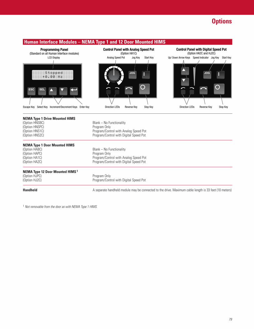
79
Options
Human Interface Modules – NEMA Type 1 and 12 Door Mounted HIMSProgramming Panel
(Standard on all Human Interface modules)
Escape Key Select Key Increment/Decrement Keys Enter Key
LCD Display
Reverse Key Stop Key
Start KeyJog Key
Direction LEDs
Control Panel with Analog Speed Pot(Option HA1C)
Analog Speed Pot
JOG
Speed Indicator
Reverse Key Stop Key
Start KeyJog KeyUp/ Down Arrow Keys
Direction LEDs
Control Panel with Digital Speed Pot(Option HA2C and HJ2C)
JOG
NEMA Type 1 Drive Mounted HIMS(Option HNSBC) Blank – No Functionality(Option HNSPC) Program Only(Option HNS1C) Program/Control with Analog Speed Pot(Option HNS2C) Program/Control with Digital Speed Pot
NEMA Type 1 Door Mounted HIMS(Option HABC) Blank – No Functionality(Option HAPC) Program Only(Option HA1C) Program/Control with Analog Speed Pot(Option HA2C) Program/Control with Digital Speed Pot
NEMA Type 12 Door Mounted HIMS 1
(Option HJPC) Program Only(Option HJ2C) Program/Control with Digital Speed Pot
Handheld A separate handheld module may be connected to the drive. Maximum cable length is 33 feet (10 meters)
1 Not removable from the door as with NEMA Type 1 HIMS.
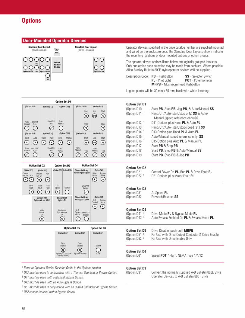
Door-Mounted Operator Devices
80
Options
1 Refer to Operator Device Function Guide in the Options section.2 D22 must be used in conjunction with a Thermal Overload or Bypass Option.3 D41 must be used with a Manual Bypass Option.4 D42 must be used with an Auto Bypass Option.5 D51 must be used in conjunction with an Output Contactor or Bypass Option.6 D52 cannot be used with a Bypass Option.
Operator devices specified in the drive catalog number are supplied mountedand wired on the enclosure door. The Standard Door Layouts shown indicatethe mounting locations of door mounted options or option groups.
The operator device options listed below are logically grouped into sets.Only one option code selection may be made from each set. Where possible,Allen-Bradley Bulletin 800E style operator devices will be supplied.
Description Code: PB = Pushbutton SS = Selector SwitchPL = Pilot Light POT = PotentiometerMHPB = Mushroom Head Pushbutton
Legend plates will be 30 mm x 50 mm, black with white lettering.
Option Set D1(Option D10) Start PB, Stop PB, Jog PB, & Auto/Manual SS(Option D11) 1 Hand/Off/Auto (start/stop only) SS & Auto/
Manual (speed reference only) SS(Option D12) 1 D11 Options plus Hand PL & Auto PL(Option D13) 1 Hand/Off/Auto (start/stop/speed ref.) SS(Option D14) 1 D13 Option plus Hand PL & Auto PL(Option D15) 1 Auto/Manual (speed reference only) SS(Option D16) 1 D15 Option plus Auto PL & Manual PL(Option D17) Start PB & Stop PB(Option D18) Start PB, Stop PB & Auto/Manual SS(Option D19) Start PB, Stop PB & Jog PB
Option Set D2(Option D21) Control Power On PL, Run PL & Drive Fault PL(Option D22) 2 D21 Options plus Motor Fault PL
Option Set D3(Option D31) At Speed PL(Option D32) Forward/Reverse SS
Option Set D4(Option D41) 3 Drive Mode PL & Bypass Mode PL(Option D42) 4 Auto Bypass Enabled On PL & Bypass Mode PL
Option Set D5 Drive Disable (push-pull) MHPB(Option D51) 5 For Use with Drive Output Contactor & Drive Enable(Option D52) 6 For Use with Drive Enable Only
Option Set D6(Option D61) Speed POT, 1-Turn, NEMA Type 1/4/12
Option Set D9(Option D91) Convert the normally supplied A-B Bulletin 800E Style
Operator Devices to A-B Bulletin 800T Style
Option Set D1
Hand/Off/Auto
Auto/Manual
Hand Auto
(Option D12)
Auto/Manual
Hand/Off/Auto
(Option D11)
Hand/Off/Auto
Hand Auto
(Option D14)
Hand/Off/Auto
Auto/Manual
(Option D13)
Auto/Manual
ManualAuto
(Option D16)
(Option D15)
Auto/Manual
Stop
StartJog
(Option D19)
PB
PB
PB
PB
Stop
StartJog
(Option D10)
PB
PB
(Option D17)
Stop
Start
PB
PB
Stop
Start
Auto/Manual
(Option D18)
PB
PB
A A A A A A
Option Set D5
(Option D61)
Speed
1-Turn
DriveDisable
(By Drive Enable)
MHPB
MHPB
(By Output Contactor& Drive Enable)
(Option D52)(Option D51)
DriveDisable
Option Set D6
Option Set D2
W
ControlPwr. On Run
DriveFault
(Option D21)
MotorFault
R
DriveFault
RunControlPwr. On
(Option D22)
Option Set D4
Drive/Off/Bypass
A.B.BypassOff/On
A.B.Enabled
DriveMode
BypassMode
Drive/Off/Bypass
Standard with AnyManual Bypass Option
Standard with AnyAuto Bypass Option Bypass
Mode
(Option D42)
(Option D41)(Option D31)
Fwd/Rev
A
AtSpeed
Option Set D3
(Option D32)
MotorHeater
On
Standard withOption -MH and -MH2
W
EnclosureSpace Heater
On
Standard withOption -EH
W W W
R
W
R R
A A
A A
Standard Door Layout(Drive Enclosure) Elapsed
TimeMeter
Option Set D1
D3
D6
D5
Option Set D2
HumanInterfaceModule
Standard Door Layout(Option Enclosure)
Option Set D4
81
Options
Operator Device Function Guide
Meter Options
Drive Start Control Drive Stop Control Drive Speed ReferencePushbutton H.I.M. Pushbutton H.I.M. H.I.M. Options Defined
Device or Selector With Remote or Selector With Remote With Control by DriveOption Mode Switch Control Contact None Switch Control Contact None Parameter #5 = Adapter 1 Parameter 1 NoneD10 Start/ • •
Stop/ • •Jog • •Auto/ • • •Manual • • •
D11 Hand/ • • • •& Off/ • •D12 Auto • • • •
Auto/ • • •Manual • • •
D13 Hand/ • • • •& Off/ • •D14 Auto • • • •D15 Auto/ • • •& Manual • • •D16
1 The function of the “Auto Mode” speed reference is dependent upon the programming of [Freq Select 2], parameter 6 in the drive. The use of an Analog Input Card isrecommended for any analog signal being fed to the drive. The function of the "Jog" mode is dependent upon the programming of [Jog Freq], parameter 24 in the drive.
Motor Run Time Meter This option provides a digital, non-resettable, door-mounted elapsed time meter. The meter is (Option ET) electrically interlocked with the Drive Run relay and Bypass contactor (if supplied) to indicate actual
motor operating hours. (Note: The standard internal drive elapsed time meter requires a HIM for viewing and is not operablein the bypass mode.)
Line Metering System, Deluxe This option provides a Powermonitor II unit at the point of incoming power to the drive package. (Option MQ2) Option includes a powermonitor and a single display. Current transformers are supplied as necessary.
Line Metering System, Basic This option provides a Powermonitor 3000 unit at the point of incoming power to the drive package. (Option MQ3) Option includes a powermonitor and a single display. Current transformers are supplied as necessary.
Voltage Barriers Protective covers for line side of disconnect switch, door-mounted devices above 50V (Option EB) (except for devices with finger safe terminals), and any foreign voltage sources.
Floor Stand This option converts a wall-mounted enclosure to a floor-mounted enclosure and adds 12" or 24" to (Option EF1) 12" High the height of the enclosure. Special consideration should be given to the final height of the drive (Option EF2) 24" High package and corresponding operator devices.
Nameplate Pin or screw-mounted 6.25" x 2" door-mounted white lamacoid nameplate with black letters. The message(Option ET) is defined by the customer at order entry – if no definition is supplied, the nameplate is shipped blank
for customer engraving.
Special Paint (Option EP1) 1-color, Special color(s) and/or type of paint. A manufacturer’s specification number and/or paint chip(Option EP2) 2-color, (Option EP3) 3-color will be required at order entry. (Note: A special primer specification is considered as one color.)
Space Heater, Remote Powered Provides (1) enclosure space heater to help prevent condensation inside the enclosure during periods(Option EH) of drive inactivity. Space heater is energized whenever drive power is removed (requires a remote 120V
AC power source). Option includes a 180W fin strip type heater and a white Enclosure Space HeaterOn pilot light mounted on the enclosure door. If remote power is not available, refer to option EH2.
Space Heater, Locally Powered Provides (1) enclosure space heater to help prevent condensation inside the enclosure during periods of(Option EH2) Requires a control drive inactivity. Space heater is energized whenever the drive is not in Run status. If the space heater power transformer option CF, CP or CT is required to run when drive power is removed refer to option EH
Filtered Door Openings Only This option provides washable metal mesh filters on the outside of the enclosure door and over all (Option EC) other vented openings. This option applies only to NEMA Type 1 drives.
Gasketed with Filtered Door Openings This option provides filtering as described in option EC. In addition all doors and wall panels will be (Option EG) gasketed as necessary to prevent unfiltered air from entering the enclosure.
ElapsedTime Meter
Enclosure Options
Codes and Standards
82
Options
Code/Standard Action
CE Consult the factory with requirements to meet the separate Low Voltage and/or EMC directives.(European Conference Standard) In most cases Packaged Drives qualify for “Restricted Industrial” applications and will only require
meeting the Low Voltage directive.
IEEE519 Provide a one-line plant power distribution drawing, and the associated harmonic specification to (Harmonic Distortion Levels) the factory, for review. A software-based harmonic analysis will be performed to determine actual
harmonic mitigation requirements.
UL, C-UL (CSA) Add a “-UL” option to the catalog string at no charge. This option provides UL panel recognition from the factory.
Approval Drawings One set 11" x 17" electrical schematics and enclosure outlines – see sample drawings at the back of this publication.
Cat. No. 1301-APPDWG (Black & Whites) Further engineering and manufacture of drive held until drawings are returned approved by Cat. No. 1301-APPRV (Velumes) the customer and any changes are approved by the manufacturer.
Manufacturing Drawings One set 11" x 17" electrical schematics and enclosure outlines – see sample drawings at the back of this publication.
Cat. No. 1301-MFDWG (Black & Whites) Information Only – Does not affect drive manufacturing. Availability is typically 2-3 weeksCat. No. 1301-MFRV (Velumes) prior to shipment of the drive(s).
Final Drawings One set 11" x 17" electrical schematics and enclosure outlines – see sample drawings at the back of this publication.
Cat. No. 1301-FINDWG (Black & Whites) Same drawings as shipped with the configured drive instruction bookCat. No. 1301-FINRV (Velumes)Cat. No. 1301-FINRM (Mylar)
Special Drawings and ReportsCat. No. 1301-TESTR Test Report, Configured Drive Only – Certifies that the configured drive has gone through test.Cat. No. 1301-CERMTR Certified Motor Dimension Drawing.Cat. No. 1301-CERXFR Certified Transformer Dimension Drawing.Cat. No. 1301-CERLR Certified Line Reactor Dimension Drawing – Not available if mounted in the drive enclosure.Cat. No. 1301-DISK AutoCAD™ Disk copy of order schematics after order has shipped.Cat. No. 1301-HARM1 Basic Harmonic Analysis – Pre-order review of customer’s one-line power distribution diagram.Cat. No. 1301-HARM2 Complete Harmonic Analysis – Post order detailed Harmonic Spectrum Analysis followed up with
a written report.Cat. No. 1301-HARM3 Deluxe Harmonic Analysis – Post order site verification of actual harmonics, detailed Spectrum
Analysis and written report.Cat. No. 1301-WT Witness Test – Customer viewing of A-B standard test procedures only. Additional tests and
documentation per customer requirements are also available.
2 Second Power Loss Implementation of a 2 second power loss fault delay time. The timer is engaged when the Fault Delay 1 [Line Loss Fault] parameter is enabled and bus voltage drops below 85%, but above minimum (Option EN910) bus voltage.
MOP Reset On Stop MOP frequency source is programmed to reset to zero following a stop.(Option EN935)
60 Hertz Maximum Frequency Maximum frequency of the drive is limited to 60 Hz.(Option EN945)
1 This option should not be used with other packaged drive options that do not have power fault delay capability.
LISTED 56L6
IND CONT EQ®C
LISTED 56L6
IND CONT EQ®
Drawing and Test Options
Custom Drive Firmware Options
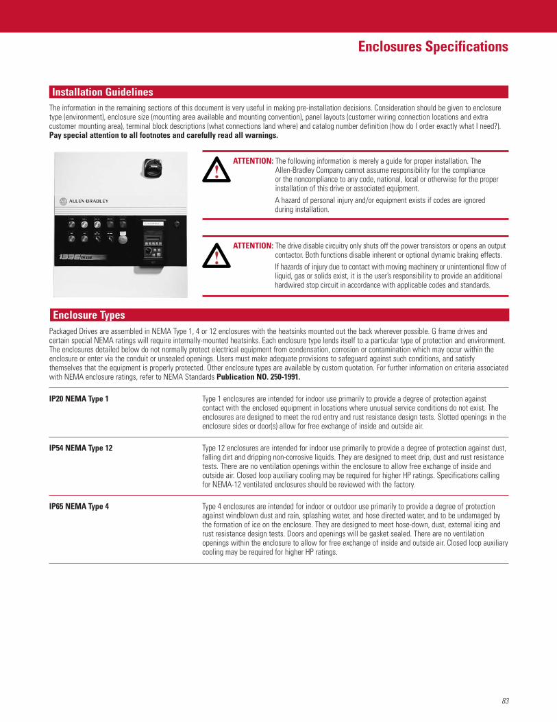
83
Enclosures Specifications
Installation Guidelines
ATTENTION: The following information is merely a guide for proper installation. The Allen-Bradley Company cannot assume responsibility for the compliance or the noncompliance to any code, national, local or otherwise for the properinstallation of this drive or associated equipment. A hazard of personal injury and/or equipment exists if codes are ignored during installation.
ATTENTION: The drive disable circuitry only shuts off the power transistors or opens an outputcontactor. Both functions disable inherent or optional dynamic braking effects.If hazards of injury due to contact with moving machinery or unintentional flow ofliquid, gas or solids exist, it is the user’s responsibility to provide an additionalhardwired stop circuit in accordance with applicable codes and standards.
Packaged Drives are assembled in NEMA Type 1, 4 or 12 enclosures with the heatsinks mounted out the back wherever possible. G frame drives andcertain special NEMA ratings will require internally-mounted heatsinks. Each enclosure type lends itself to a particular type of protection and environment.The enclosures detailed below do not normally protect electrical equipment from condensation, corrosion or contamination which may occur within theenclosure or enter via the conduit or unsealed openings. Users must make adequate provisions to safeguard against such conditions, and satisfythemselves that the equipment is properly protected. Other enclosure types are available by custom quotation. For further information on criteria associatedwith NEMA enclosure ratings, refer to NEMA Standards Publication NO. 250-1991.
IP20 NEMA Type 1 Type 1 enclosures are intended for indoor use primarily to provide a degree of protection againstcontact with the enclosed equipment in locations where unusual service conditions do not exist. Theenclosures are designed to meet the rod entry and rust resistance design tests. Slotted openings in theenclosure sides or door(s) allow for free exchange of inside and outside air.
IP54 NEMA Type 12 Type 12 enclosures are intended for indoor use primarily to provide a degree of protection against dust,falling dirt and dripping non-corrosive liquids. They are designed to meet drip, dust and rust resistancetests. There are no ventilation openings within the enclosure to allow free exchange of inside andoutside air. Closed loop auxiliary cooling may be required for higher HP ratings. Specifications callingfor NEMA-12 ventilated enclosures should be reviewed with the factory.
IP65 NEMA Type 4 Type 4 enclosures are intended for indoor or outdoor use primarily to provide a degree of protectionagainst windblown dust and rain, splashing water, and hose directed water, and to be undamaged bythe formation of ice on the enclosure. They are designed to meet hose-down, dust, external icing andrust resistance design tests. Doors and openings will be gasket sealed. There are no ventilationopenings within the enclosure to allow for free exchange of inside and outside air. Closed loop auxiliarycooling may be required for higher HP ratings.
The information in the remaining sections of this document is very useful in making pre-installation decisions. Consideration should be given to enclosuretype (environment), enclosure size (mounting area available and mounting convention), panel layouts (customer wiring connection locations and extracustomer mounting area), terminal block descriptions (what connections land where) and catalog number definition (how do I order exactly what I need?).Pay special attention to all footnotes and carefully read all warnings.
Enclosure Types
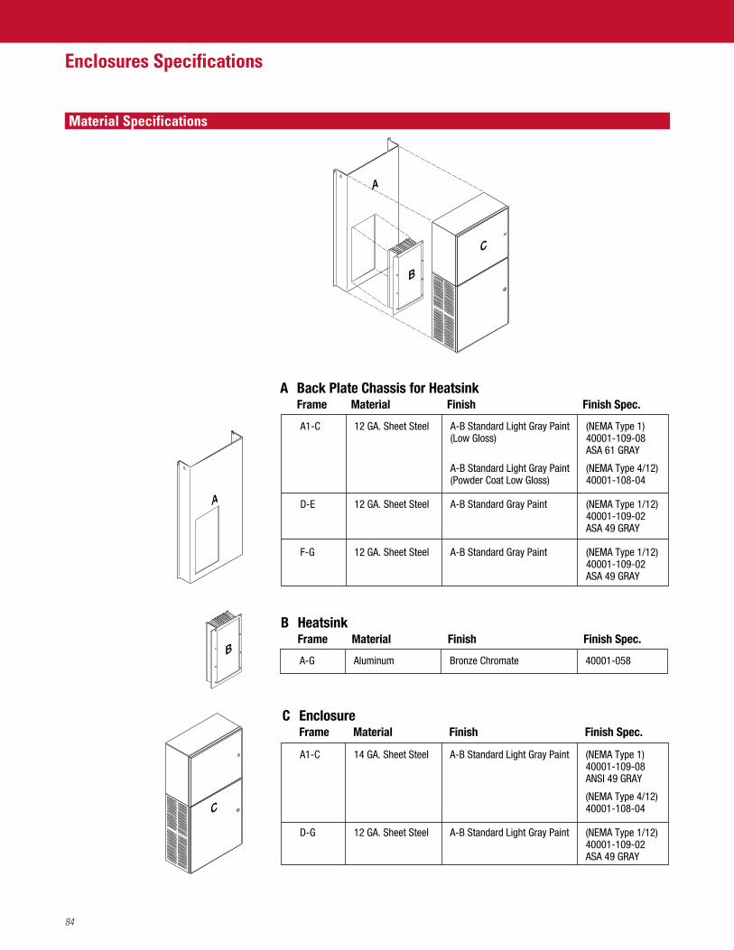
Material Specifications
84
Enclosures Specifications
A-G Aluminum Bronze Chromate 40001-058
B HeatsinkFrame Material Finish Finish Spec.
A Back Plate Chassis for HeatsinkFrame Material Finish Finish Spec.
A1-C 12 GA. Sheet Steel A-B Standard Light Gray Paint (NEMA Type 1)(Low Gloss) 40001-109-08
ASA 61 GRAY
A-B Standard Light Gray Paint (NEMA Type 4/12)(Powder Coat Low Gloss) 40001-108-04
D-E 12 GA. Sheet Steel A-B Standard Gray Paint (NEMA Type 1/12)40001-109-02ASA 49 GRAY
F-G 12 GA. Sheet Steel A-B Standard Gray Paint (NEMA Type 1/12)40001-109-02ASA 49 GRAY
A1-C 14 GA. Sheet Steel A-B Standard Light Gray Paint (NEMA Type 1)40001-109-08ANSI 49 GRAY
(NEMA Type 4/12)40001-108-04
D-G 12 GA. Sheet Steel A-B Standard Light Gray Paint (NEMA Type 1/12)40001-109-02ASA 49 GRAY
C EnclosureFrame Material Finish Finish Spec.
A
C
B
B
A
C
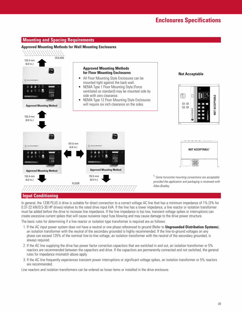
85
Enclosures Specifications
Mounting and Spacing Requirements
In general, the 1336 PLUS II drive is suitable for direct connection to a correct voltage AC line that has a minimum impedance of 1% (3% for0.37-22 kW/0.5-30 HP drives) relative to the rated drive input kVA. If the line has a lower impedance, a line reactor or isolation transformermust be added before the drive to increase line impedance. If the line impedance is too low, transient voltage spikes or interruptions cancreate excessive current spikes that will cause nuisance input fuse blowing and may cause damage to the drive power structure.The basic rules for determining if a line reactor or isolation type transformer is required are as follows:
1. If the AC input power system does not have a neutral or one phase referenced to ground (Refer to Ungrounded Distribution Systems), an isolation transformer with the neutral of the secondary grounded is highly recommended. If the line-to-ground voltages on any phase can exceed 125% of the nominal line-to-line voltage, an isolation transformer with the neutral of the secondary grounded, isalways required.
2. If the AC line supplying the drive has power factor correction capacitors that are switched in and out, an isolation transformer or 5%reactors are recommended between the capacitors and drive. If the capacitors are permanently connected and not switched, the generalrules for impedance mismatch above apply.
3. If the AC line frequently experiences transient power interruptions or significant voltage spikes, an isolation transformer or 5% reactorsare recommended.
Line reactors and isolation transformers can be ordered as loose items or installed in the drive enclosure.
101.6 mm(4.0 in.)
Not Acceptable
NOT ACCEPTABLE 1
Approved Mounting Method Approved Mounting Method
Approved Mounting Method
Approved Mounting Methods for Wall Mounting Enclosures
ΙΙ
NO
T A
CCEP
TAB
LE
152.4 mm(6.0 In.)
152.4 mm(6.0 In.)
152.4 mm(6.0 In.)
152.4 mm(6.0 In.)
Input Conditioning
1 Some horizontal mounting conventions are acceptableprovided the application and packaging is reviewed withAllen-Bradley.
FLOOR
CEILING
Approved Mounting Methods for Floor Mounting Enclosures
• All Floor Mounting Style Enclosures can be mounted tight against the back wall.
• NEMA Type 1 Floor Mounting Style (Force ventilated as standard) may be mounted side by side with zero clearance.
• NEMA Type 12 Floor Mounting Style Enclosureswill require six inch clearance on the sides.
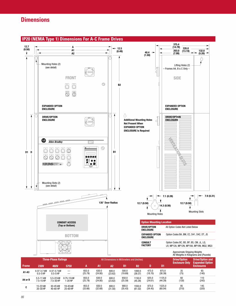
40.4(1.59)
Mounting Slots (2)(see detail)
B1
B2
A2A1A
Mounting Holes (2)(see detail)
DD1
DRIVE/OPTIONENCLOSURE
EXPANDED OPTIONENCLOSURE
DRIVE/OPTIONENCLOSURE
EXPANDED OPTIONENCLOSURE
Additional Mounting HolesNot Present When EXPANDED OPTION ENCLOSURE Is Required
135° Door Radius
All Option Codes Not Listed BelowDRIVE/OPTIONENCLOSURE
Option Codes BC, BD, BP, BS, CM, JL, LQ, LR, MP12A, MP12N, MP18A, MP18N, MQ2, MQ3
CONSULTFACTORY
Option Codes BA, BM, CC, D41, D42, DT, JSEXPANDED OPTIONENCLOSURE
Approximate Shipping WeightsAll Weights in Kilograms and (Pounds)
All Dimensions in Millimeters and (Inches)
Frame
A1-A3
A4 or B
C
575V
——
0.75-15 kW1-20 HP
19-45 kW25-60 HP
230V
0.37-3.7 kW0.5-5 HP
5.5-11 kW7.5-15 HP
15-22 kW20-30 HP
460V
0.37-3.7 kW0.5-5 HP
5.5-22 kW7.5-30 HP
30-45 kW40-60 HP
B1
500.0(19.69)
650.0(25.59)
900.0(35.43)
B2
1000.0(39.37)
1150.0(45.28)
1550.0(61.02)
A2
600.0(23.62)
600.0(23.62)
800.0(31.50)
D
475.0(18.70)
625.0(24.61)
875.0(34.45)
D1
975.0(38.39)
1125.0(44.29)
1525.0(60.04)
A1
630.0(24.80)
630.0(24.80)
830.0(32.68)
A
655.0(25.79)
655.0(25.79)
855.0(33.66)
35(75)
60(130)
95(210)
65(140)
110(243)
145(320)
Drive/Option andExpanded OptionEnclosures
Three-Phase Ratings
Mounting Holes
7.1 (0.28)
12.7 (0.50)14.3 (0.56)
Mounting Slots
12.7 (0.50)
7.9 (0.31)
203.0(7.99)
335.0(13.19)
375.4(14.78)
132.0(5.20)
CONDUIT ACCESS(Top or Bottom)
BOTTOM
FRONT SIDE
VENTILATION SLOTS
POWER ONAT SPEED
HAND AUTO DRIVE FAULTHAND OFF
AUTO AUTO MANUAL
EMERGENCY
STOP
MOTOR FAULTDRIVE FAULTDRIVE RUN
AUTO BYPASSOFF ON DRIVE BYPASS
OFF
DRIVE MODE BYPASS MODE
ON
OFF
ON
OFF
12.7(0.50) 12.5
(0.49)
Lifting Holes (2)– Frames A4, B & C Only –
Option Mounting Location
Drive/OptionEnclosure Only
II
IP20 (NEMA Type 1) Dimensions For A-C Frame Drives
86
Dimensions
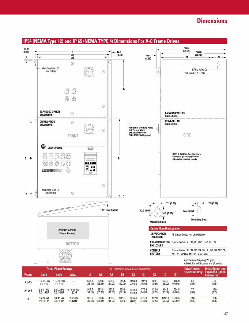
87
Dimensions
IP54 (NEMA Type 12) and IP 65 (NEMA TYPE 4) Dimensions For A-C Frame Drives
135° Door Radius
Approximate Shipping WeightsAll Weights in Kilograms and (Pounds)
All Dimensions in Millimeters and (Inches)
Frame
A1-A3
A4 or B
C
575V
——
0.75-15 kW1-20 HP
19-45 kW25-60 HP
230V
0.37-3.7 kW0.5-5 HP
5.5-11 kW7.5-15 HP
15-22 kW20-30 HP
460V
0.37-3.7 kW0.5-5 HP
5.5-22 kW7.5-30 HP
30-45 kW40-60 HP
B1
685.8(27.00)
939.8(37.00)
1320.8(52.0)
A2
609.6(24.00)
863.6(34.00)
863.6(34.00)
B2
1193.8(47.00)
1549.4(61.00)
1930.4(76.0)
C1
407.9(16.06)
375.9(14.80)
375.9(14.80)
D
660.9(26.02)
914.9(36.02)
1295.9(51.02)
D1
1168.9(46.02)
1524.5(60.02)
1905.5(75.02)
C2
100.1(3.94)
132.0(5.20)
132.0(5.20)
A1
639.8(25.19)
893.8(35.19)
893.8(35.19)
A
664.7(26.17)
918.7(36.17)
918.7(36.17)
50(110)
77(170)
116(255)
Drive/OptionEnclosure Only
79(175)
129(285)
166(365)
Drive/Option andExpanded OptionEnclosures
Three-Phase Ratings
CONDUIT ACCESS(Top or Bottom)
BOTTOM
Mounting Slots (2)(see detail)
B1
B2
C1 C2A2A1A
Mounting Holes (2)(see detail)
ON
OFF
DD1
DRIVE/OPTIONENCLOSURE
DRIVE/OPTIONENCLOSURE
EXPANDED OPTIONENCLOSURE
EXPANDED OPTIONENCLOSURE
FRONT
40.4(1.59)
SIDE
DRIVE/OPTIONENCLOSURE
Option Codes BC, BD, BP, BS, CM, JL, LQ, LR, MP12A, MP12N, MP18A, MP18N, MQ2, MQ3
CONSULTFACTORY
Option Codes BA, BM, CC, D41, D42, DT, JSEXPANDED OPTIONENCLOSURE
Option Mounting Location
All Option Codes Not Listed Below
Mounting Holes
7.1 (0.28)
12.7 (0.50)14.3 (0.56)
Mounting Slots
12.7 (0.50)
7.9 (0.31)
POWER ONAT SPEED
HAND AUTO DRIVE FAULTHAND OFF
AUTO AUTO MANUAL
EMERGENCY
STOP
MOTOR FAULTDRIVE FAULTDRIVE RUN
AUTO BYPASSOFF ON DRIVE BYPASS
OFF
DRIVE MODE BYPASS MODE
508.0(20.00)
548.4(21.59)
Lifting Holes (2)– Frames A4, B & C Only –
12.70(0.50) 12.5
(0.49)
Additional Mounting HolesNot Present When EXPANDED OPTION ENCLOSURE Is Required
NOTE: IP 65 (NEMA Type 4) will have waterproof gasketing system and drive/option mounting chassis.
II
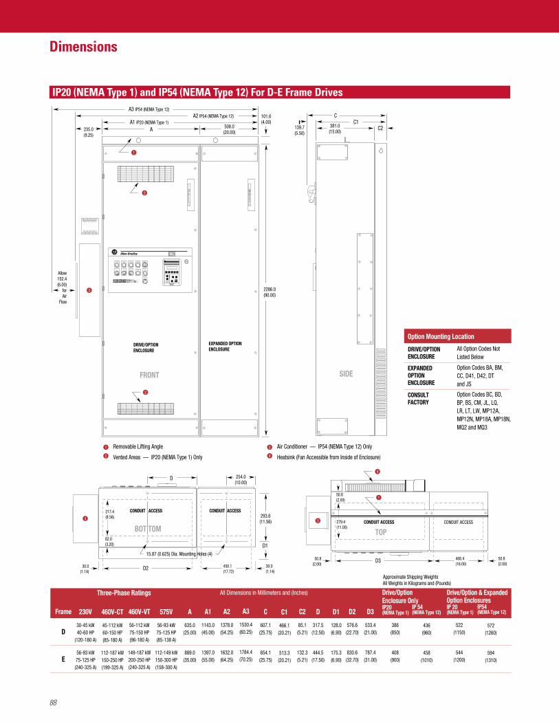
IP20 (NEMA Type 1) and IP54 (NEMA Type 12) For D-E Frame Drives
88
Dimensions
235.0(9.25)
AA1 IP20 (NEMA Type 1)
A3 IP54 (NEMA Type 12)A2 IP54 (NEMA Type 12)
508.0(20.00)
2
1
2
DRIVE/OPTIONENCLOSURE
EXPANDED OPTIONENCLOSURE
1 Removable Lifting Angle
Vented Areas — IP20 (NEMA Type 1) Only2
Air Conditioner — IP54 (NEMA Type 12) Only
Heatsink (Fan Accessible from Inside of Enclosure)
3
4
3
Allow152.4(6.00)
forAir
Flow
Option Codes BA, BM, CC, D41, D42, DT and JS
EXPANDEDOPTIONENCLOSURE
Option Codes BC, BD,BP, BS, CM, JL, LQ,LR, LT, LW, MP12A,MP12N, MP18A, MP18N, MQ2 and MQ3
CONSULTFACTORY
Option Mounting Location
All Option Codes NotListed Below
DRIVE/OPTIONENCLOSURE
BOT TOM
FRONT
D1
CONDUIT ACCESS
D
CONDUIT ACCESS CONDUIT ACCESS
TOP
CONDUIT ACCESS
C1C2
C
SIDE
381.0(15.00)
139.7(5.50)
2286.0(90.00)
101.6(4.00)
293.6(11.56) 279.4
(11.00)
50.8(2.00)
254.0(10.00)
3 3
4
1
POWER ONAT SPEED
HAND AUTO DRIVE FAULTHAND OFF
AUTO AUTO MANUAL
EMERGENCY
STOP
MOTOR FAULTDRIVE FAULTDRIVE RUN
406.4(16.00)
50.8(2.00)
D350.8(2.00)450.1
(17.72)30.0(1.14)
D230.0(1.14)
217.4(8.56)
82.0(3.20)
Approximate Shipping Weights
All Dimensions in Millimeters and (Inches)
All Weights in Kilograms and (Pounds)
Frame
D
E
575V
56-93 kW75-125 HP(85-138 A)
112-149 kW150-300 HP(158-300 A)
460V-CT
45-112 kW60-150 HP(85-180 A)
112-187 kW150-250 HP(199-325 A)
460V-VT
56-112 kW75-150 HP(96-180 A)
149-187 kW200-250 HP(240-325 A)
230V
30-45 kW40-60 HP
(120-180 A)
56-93 kW75-125 HP(240-325 A)
C
607.1(25.75)
654.1(25.75)
C1
466.1(20.21)
513.3(20.21)
C2
85.1(5.21)
132.3(5.21)
D
317.5(12.50)
444.5(17.50)
D1
128.0(6.90)
175.3(6.90)
D2
576.6(22.70)
830.6(32.70)
D3
533.4(21.00)
787.4(31.00)
A1
1143.0(45.00)
1397.0(55.00)
A2
1378.0(54.25)
1632.0(64.25)
A3
1530.4(60.25)
1784.4(70.25)
A
635.0(25.00)
889.0(35.00)
Drive/Option Enclosure OnlyIP20(NEMA Type 1)
IP 54(NEMA Type 12)
Drive/Option & Expanded Option EnclosuresIP 20(NEMA Type 1)
IP54(NEMA Type 12)
Three-Phase Ratings
15.87 (0.625) Dia. Mounting Holes (4)15.87 (0.625) Dia. Mounting Holes (4)
II
386(850)
408(900)
436(960)
458(1010)
522(1150)
544(1200)
572(1260)
594(1310)
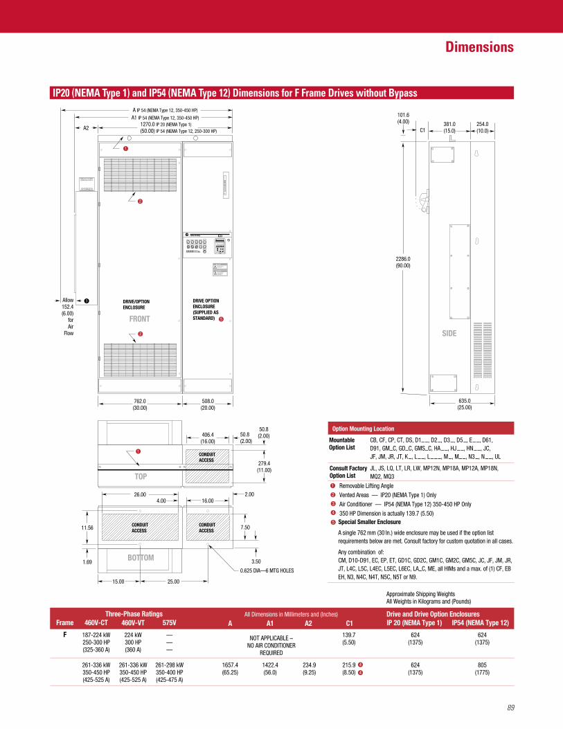
89
Dimensions
IP20 (NEMA Type 1) and IP54 (NEMA Type 12) Dimensions for F Frame Drives without Bypass
DRIVE/OPTIONENCLOSURE
CONDUITACCESS
CONDUITACCESS
CONDUITACCESS
DRIVE OPTIONENCLOSURE(SUPPLIED ASSTANDARD)
ELECTRICAL SHOCK HAZARD FROMENERGY STORAGE CAPACITORS.VERIFY LOW VOLTAGE DISCHARGEBEFORE SERVICING.SEE INSTRUCTION MANUAL.
DANGERREMOTE SOURCE(S) OF POWERDISCONNECT ALL SOURCES OF POWERBEFORE OPENING DOOR.
DANGER
762.0(30.00)
508.0(20.00)
FRONT
2
TOP
SIDE
406.4(16.00)
50.8(2.00)
50.8(2.00)
279.4(11.00)
1
JL, JS, LQ, LT, LR, LW, MP12N, MP18A, MP12A, MP18N, MQ2, MQ3
Consult FactoryOption List
CB, CF, CP, CT, DS, D1– –, D2 –, D3
–, D5 –, E
– –, D61, D91, GM–C, GD–C, GMS–C, HA
– –, HJ – –, HN
– –, JC, JF, JM, JR, JT, K
–, L – –, L
– – –, M –, M– –, N3
–, N – –, UL
MountableOption List
Option Mounting Location
A single 762 mm (30 In.) wide enclosure may be used if the option listrequirements below are met. Consult factory for custom quotation in all cases.
Any combination of:CM, D10-D91, EC, EP, ET, GD1C, GD2C, GM1C, GM2C, GM5C, JC, JF, JM, JR,JT, L4C, L5C, L4EC, L5EC, L6EC, LA–C, ME, all HIMs and a max. of (1) CF, EBEH, N3, N4C, N4T, N5C, N5T or N9.
Special Smaller Enclosure
1270.0 IP 20 (NEMA Type 1)(50.00) IP 54 (NEMA Type 12, 250-300 HP)
A1 IP 54 (NEMA Type 12, 350-450 HP)
A IP 54 (NEMA Type 12, 350-450 HP)
A2
3Allow152.4(6.00)
forAir
Flow
C1
1 Removable Lifting AngleVented Areas — IP20 (NEMA Type 1) OnlyAir Conditioner — IP54 (NEMA Type 12) 350-450 HP Only350 HP Dimension is actually 139.7 (5.50)
2
3
4
4
5
IP 20 (NEMA Type 1) IP54 (NEMA Type 12)Drive and Drive Option EnclosuresAll Dimensions in Millimeters and (Inches)
460V-CT
261-336 kW350-450 HP(425-525 A)
460V-VT
261-336 kW350-450 HP(425-525 A)
575V
261-298 kW350-400 HP(425-475 A)
187-224 kW250-300 HP(325-360 A)
224 kW300 HP(360 A)
———
A
1657.4(65.25)
A1 A2 C1
1422.4(56.0)
234.9(9.25)
215.9(8.50) 4
NOT APPLICABLE –NO AIR CONDITIONER
REQUIRED
139.7(5.50)
624(1375)
624(1375)
805(1775)
624(1375)
Frame
F
Three-Phase Ratings
POWER ONAT SPEED
HAND AUTODRIVE FAULT
HAND OFF
AUTO AUTO MANUAL
EMERGENCY
STOP
MOTOR FAULTDRIVE FAULTDRIVE RUN
Approximate Shipping WeightsAll Weights in Kilograms and (Pounds)
2
5
1
635.0(25.00)
101.6(4.00) 381.0
(15.0)254.0(10.0)
2286.0(90.00)
26.00
15.00 25.00
4.00 16.00
BOTTOM
11.56
1.69
7.50
3.50
0.625 DIA—6 MTG HOLES
2.00
II
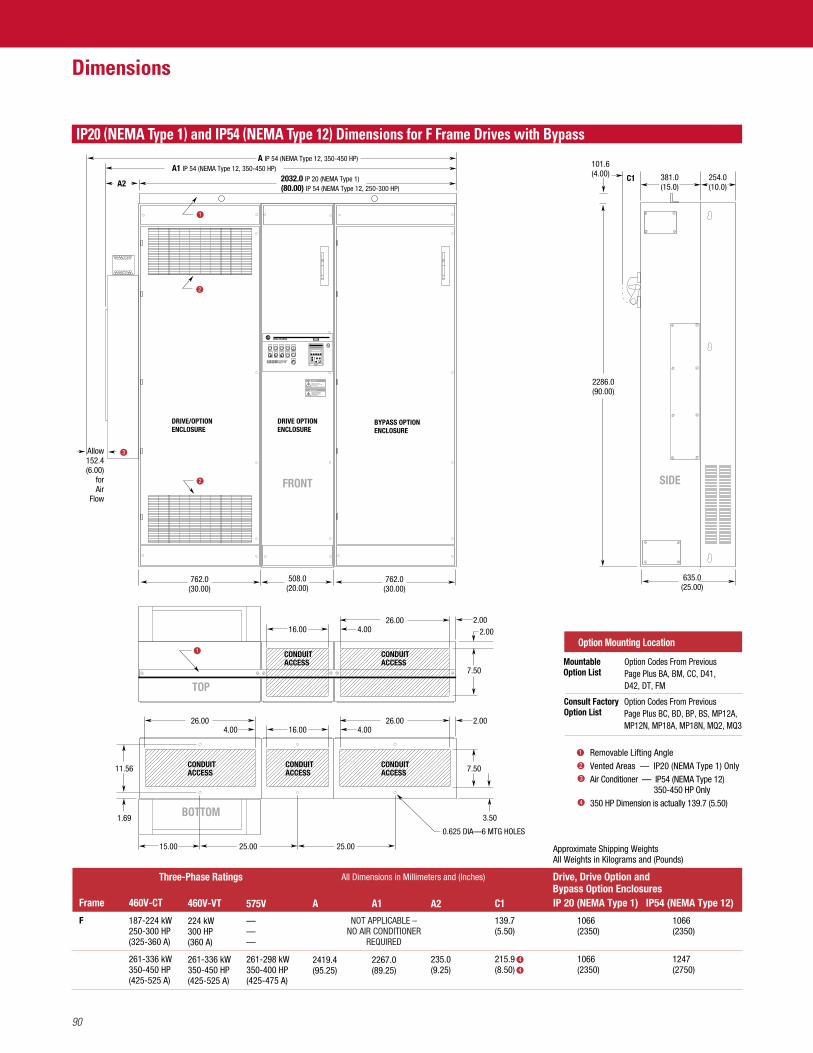
IP20 (NEMA Type 1) and IP54 (NEMA Type 12) Dimensions for F Frame Drives with Bypass
90
Dimensions
1 Removable Lifting AngleVented Areas — IP20 (NEMA Type 1) OnlyAir Conditioner — IP54 (NEMA Type 12)
350-450 HP Only350 HP Dimension is actually 139.7 (5.50)
2
3
4
4
4
2032.0 IP 20 (NEMA Type 1)(80.00) IP 54 (NEMA Type 12, 250-300 HP)
A1 IP 54 (NEMA Type 12, 350-450 HP)A IP 54 (NEMA Type 12, 350-450 HP)
1
DRIVE/OPTIONENCLOSURE
DRIVE OPTIONENCLOSURE
CONDUITACCESS
CONDUITACCESS
CONDUITACCESS
CONDUITACCESS
CONDUITACCESS
BYPASS OPTIONENCLOSURE
ELECTRICAL SHOCK HAZARD FROMENERGY STORAGE CAPACITORS.VERIFY LOW VOLTAGE DISCHARGEBEFORE SERVICING.SEE INSTRUCTION MANUAL.
DANGERREMOTE SOURCE(S) OF POWERDISCONNECT ALL SOURCES OF POWERBEFORE OPENING DOOR.
DANGER
762.0(30.00)
762.0(30.00)
508.0(20.00)
FRONT
Option Codes From PreviousPage Plus BC, BD, BP, BS, MP12A,MP12N, MP18A, MP18N, MQ2, MQ3
Consult FactoryOption List
Option Codes From PreviousPage Plus BA, BM, CC, D41,D42, DT, FM
MountableOption List
2
3
2
Allow152.4(6.00)
forAir
Flow
POWER ONAT SPEED
HAND AUTODRIVE FAULT
HAND OFF
AUTO AUTO MANUAL
EMERGENCY
STOP
MOTOR FAULTDRIVE FAULTDRIVE RUN
A2
Approximate Shipping WeightsAll Weights in Kilograms and (Pounds)
IP 20 (NEMA Type 1) IP54 (NEMA Type 12)
Drive, Drive Option andBypass Option Enclosures
All Dimensions in Millimeters and (Inches)
460V-CT
187-224 kW250-300 HP(325-360 A)
261-336 kW350-450 HP(425-525 A)
460V-VT
224 kW300 HP(360 A)
261-336 kW350-450 HP(425-525 A)
575V
———
261-298 kW350-400 HP(425-475 A)
A
2419.4(95.25)
A1
2267.0(89.25)
A2
235.0(9.25)
C1
139.7(5.50)
215.9(8.50)
1066(2350)
1066(2350)
1066(2350)
1247(2750)
Frame
F
Three-Phase Ratings
NOT APPLICABLE –NO AIR CONDITIONER
REQUIRED
TOP
SIDE
7.5011.56
3.50
7.50
1.69
0.625 DIA—6 MTG HOLES
1
635.0(25.00)
101.6(4.00) 381.0
(15.0)254.0(10.0)
2286.0(90.00)
26.00 26.00 2.00
2.002.00
15.00 25.00 25.00
4.00 4.0016.00
26.004.0016.00
C1
II
BOTTOM
Option Mounting Location
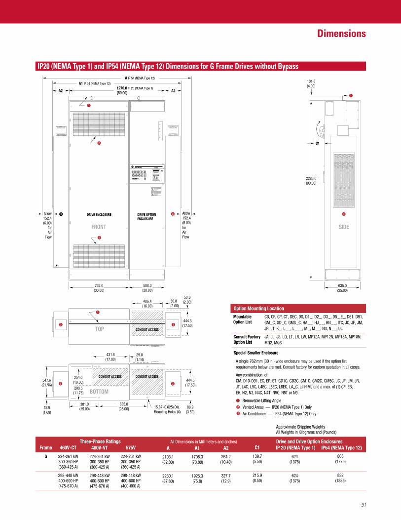
91
Dimensions
IP20 (NEMA Type 1) and IP54 (NEMA Type 12) Dimensions for G Frame Drives without Bypass
DRIVE ENCLOSURE DRIVE OPTIONENCLOSURE
ELECTRICAL SHOCK HAZARD FROMENERGY STORAGE CAPACITORS.VERIFY LOW VOLTAGE DISCHARGEBEFORE SERVICING.SEE INSTRUCTION MANUAL.
DANGERREMOTE SOURCE(S) OF POWERDISCONNECT ALL SOURCES OF POWERBEFORE OPENING DOOR.
DANGER
762.0(30.00)
508.0(20.00)
FRONT
2
635.0(25.00)
1
SIDE
3
TOP CONDUIT ACCESS
406.4(16.00)
50.8(2.00)
50.8(2.00)
444.5(17.50)
1
33
BOTTOM
29.0(1.14)
431.8(17.00)
CONDUIT ACCESSCONDUIT ACCESS
635.0(25.00)
381.0(15.00)
3 3547.6(21.56)
254.0(10.00)298.5(11.75)
42.9(1.69)
88.9(3.50)
444.5(17.50)
15.87 (0.625) Dia.Mounting Holes (4)
JA, JL, JS, LQ, LT, LR, LW, MP12A, MP12N, MP18A, MP18N,MQ2, MQ3
Consult FactoryOption List
CB, CF, CP, CT, DEC, DS, D1 –, D2
–, D3 –, D5
–,E–, D61, D91, GM
–C, GD –C, GMS
–C, HA – –, HJ
– –, HN – –, ITC, JC, JF, JM,
JR, JT, K –, L
– –, L – – –, M
–, M – –, N3, N
– –, UL
MountableOption List
Option Mounting Location
A single 762 mm (30 In.) wide enclosure may be used if the option listrequirements below are met. Consult factory for custom quotation in all cases.
Any combination of:CM, D10-D91, EC, EP, ET, GD1C, GD2C, GM1C, GM2C, GM5C, JC, JF, JM, JR,JT, L4C, L5C, L4EC, L5EC, L6EC, LA–C, all HIMs and a max. of (1) CF, EB,EH, N2, N3, N4C, N4T, N5C, N5T or N9.
Special Smaller Enclosure
1270.0 IP 20 (NEMA Type 1)(50.00)
A1 IP 54 (NEMA Type 12)
A IP 54 (NEMA Type 12)
A2
3Allow152.4(6.00)
forAir
Flow
A2
3 Allow152.4(6.00)forAirFlow
101.6(4.00)
2286.0(90.00)
C1
1 Removable Lifting AngleVented Areas — IP20 (NEMA Type 1) OnlyAir Conditioner — IP54 (NEMA Type 12) Only
2
3
IP 20 (NEMA Type 1) IP54 (NEMA Type 12)Drive and Drive Option EnclosuresAll Dimensions in Millimeters and (Inches)
460V-CT
224-261 kW300-350 HP(360-425 A)
298-448 kW400-600 HP(475-670 A)
460V-VT
224-261 kW300-350 HP(360-425 A)
298-448 kW400-600 HP(475-670 A)
575V
224-261 kW300-350 HP(360-425 A)
298-448 kW400-600 HP(400-600 A)
A
2103.1(82.80)
2230.1(87.80)
A1
1798.3(70.80)
1925.3(75.8)
A2
264.2(10.40)
327.7(12.9)
C1
139.7(5.50)
215.9(8.50)
624(1375)
624(1375)
805(1775)
832(1885)
Frame
G
Three-Phase Ratings
POWER ONAT SPEED
HAND AUTODRIVE FAULT
HAND OFF
AUTO AUTO MANUAL
EMERGENCY
STOP
MOTOR FAULTDRIVE FAULTDRIVE RUN
Approximate Shipping WeightsAll Weights in Kilograms and (Pounds)
2
1
II
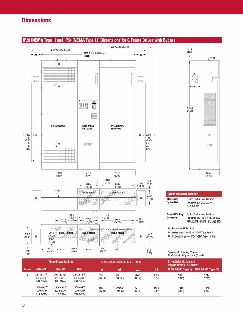
IP20 (NEMA Type 1) and IP54 (NEMA Type 12) Dimensions for G Frame Drives with Bypass
92
Dimensions
1 Removable Lifting AngleVented Areas — IP20 (NEMA Type 1) OnlyAir Conditioner — IP54 (NEMA Type 12) Only
2
3
101.6(4.00)
2286.0(90.00)
635.0(25.00)
SIDE
BOTTOM
15.87 (0.625) Dia. — Mounting Holes (6)
431.8(17.00)
406.4(16.00)
CONDUIT ACCESSCONDUIT ACCESS
635.0(25.00)
635.0(25.00)
381.0(15.00)
547.6(21.56)
88.9(3.50)
444.5(17.50)
CONDUIT ACCESS
29.0(1.14) 50.8
(2.00)
101.6(4.00) 660.4
(26.00)
254.0(10.00)298.5(11.75)
42.9(1.69)
CONDUIT ACCESS CONDUIT ACCESS
50.8(2.00)
444.5(17.50)
406.4(16.00)
50.8(2.00)
101.6(4.00) 660.4
(26.00)
TOP
2032.0 IP 20 (NEMA Type 1)(80.00)
A1 IP 54 (NEMA Type 12)A IP 54 (NEMA Type 12)
C1
A2
1
1
DRIVE ENCLOSURE DRIVE OPTIONENCLOSURE
BYPASS OPTIONENCLOSURE
ELECTRICAL SHOCK HAZARD FROMENERGY STORAGE CAPACITORS.VERIFY LOW VOLTAGE DISCHARGEBEFORE SERVICING.SEE INSTRUCTION MANUAL.
DANGERREMOTE SOURCE(S) OF POWERDISCONNECT ALL SOURCES OF POWERBEFORE OPENING DOOR.
DANGER
762.0(30.00)
762.0(30.00)
508.0(20.00)
FRONT
Option Codes From PreviousPage Plus BC, BD, BP, BS, MP12A,MP12N, MP18A, MP18N, MQ2, MQ3
Consult FactoryOption List
Option Codes From PreviousPage Plus BA, BM, CC, D41,D42, DT, FM
MountableOption List
2
3 3
2
1
Allow152.4(6.00)
forAir
Flow
3
33
33
Allow152.4(6.00)forAirFlow
POWER ONAT SPEED
HAND AUTODRIVE FAULT
HAND OFF
AUTO AUTO MANUAL
EMERGENCY
STOP
MOTOR FAULTDRIVE FAULTDRIVE RUN
A2
Approximate Shipping WeightsAll Weights in Kilograms and (Pounds)
IP 20 (NEMA Type 1) IP54 (NEMA Type 12)
Drive, Drive Option andBypass Option Enclosures
All Dimensions in Millimeters and (Inches)
460V-CT
224-261 kW300-350 HP(360-425 A)
298-448 kW400-600 HP(475-670 A)
460V-VT
224-261 kW300-350 HP(360-425 A)
298-448 kW400-600 HP(475-670 A)
575V
224-261 kW300-350 HP(360-425 A)
298-448 kW400-600 HP(400-600 A)
A
2865.1(112.80)
2992.1(117.80)
A1
2560.3(100.80)
2687.3(105.80)
A2
264.2(10.40)
327.7(12.90)
C1
139.7(5.50)
215.9(8.50)
1066(2350)
1066(2350)
1247(2750)
1275(2810)
Frame
G
Three-Phase Ratings
Option Mounting Location
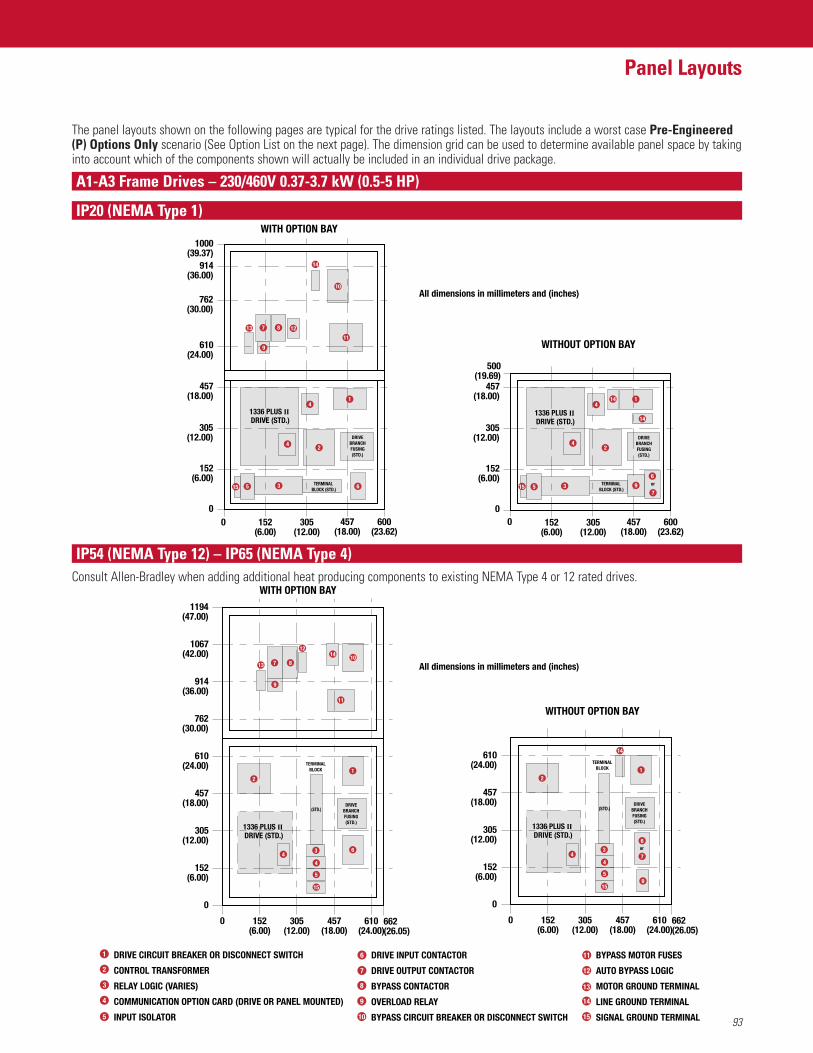
93
Panel Layouts
A1-A3 Frame Drives – 230/460V 0.37-3.7 kW (0.5-5 HP)
IP20 (NEMA Type 1)
The panel layouts shown on the following pages are typical for the drive ratings listed. The layouts include a worst case Pre-Engineered(P) Options Only scenario (See Option List on the next page). The dimension grid can be used to determine available panel space by takinginto account which of the components shown will actually be included in an individual drive package.
WITH OPTION BAY
All dimensions in millimeters and (inches)
All dimensions in millimeters and (inches)
WITHOUT OPTION BAY
10
13
14
11
1287
6
9
41
2
35
DRIVEBRANCHFUSING(STD.)
914(36.00)
1000(39.37)
762(30.00)
610(24.00)
457(18.00)
305(12.00)
305(12.00)
152(6.00)
152(6.00)
00 457
(18.00)600
(23.62)
41
14
2
6
7935
1336 PLUS II DRIVE (STD.)
1336 PLUS II DRIVE (STD.)
DRIVEBRANCHFUSING(STD.)
or
457(18.00)
500(19.69)
305(12.00)
305(12.00)
152(6.00)
152(6.00)
00 457
(18.00)600
(23.62)
TERMINAL BLOCK (STD.)
TERMINAL BLOCK (STD.)1515
4
14
4
14
WITHOUT OPTION BAY762
(30.00)
610(24.00)
305(12.00)
457(18.00)
152(6.00)
152(6.00)
457(18.00)
0 662(26.05)
305(12.00)
610(24.00)
WITH OPTION BAY
914(36.00)
1067(42.00)
1194(47.00)
6
7
7 8
9
12
10
1
6
4
5
15
11
DRIVEBRANCHFUSING(STD.)
(STD.)
2
3
0
610(24.00)
305(12.00)
457(18.00)
152(6.00)
152(6.00)
457(18.00)
0 662(26.05)
305(12.00)
610(24.00)
1
DRIVEBRANCHFUSING(STD.)
or
2
0
9
44
14
13
4
5
(STD.)
3
TERMINALBLOCK
15
TERMINALBLOCK
1336 PLUS II DRIVE (STD.)
1336 PLUS II DRIVE (STD.)
DRIVE CIRCUIT BREAKER OR DISCONNECT SWITCH
CONTROL TRANSFORMER
RELAY LOGIC (VARIES)
COMMUNICATION OPTION CARD (DRIVE OR PANEL MOUNTED)
INPUT ISOLATOR
1
4
5
6
72
3
DRIVE INPUT CONTACTOR
DRIVE OUTPUT CONTACTOR
BYPASS CONTACTOR
OVERLOAD RELAY
BYPASS CIRCUIT BREAKER OR DISCONNECT SWITCH
8
9
10
11
12
BYPASS MOTOR FUSES
AUTO BYPASS LOGIC
MOTOR GROUND TERMINAL
LINE GROUND TERMINAL
SIGNAL GROUND TERMINAL
13
14
15
IP54 (NEMA Type 12) – IP65 (NEMA Type 4)Consult Allen-Bradley when adding additional heat producing components to existing NEMA Type 4 or 12 rated drives.
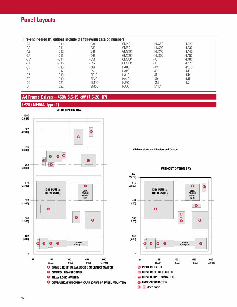
IP20 (NEMA Type 1)
A4 Frame Drives – 460V 5.5-15 kW (7.5-20 HP)
94
Panel Layouts
0
0
1000(39.37)
1067(42.00)
916(36.00)
762(30.00)
610(24.00)
457(18.00)
305(12.00)
152(6.00)
152(6.00)
305(12.00)
457(18.00)
600(23.62)
WITH OPTION BAY
5 3
2
4
1
13
14
14
11
10
DRIVEBRANCHFUSING(STD.)
7 8 12
0
0
610(24.00)
650(25.59)
457(18.00)
305(12.00)
152(6.00)
152(6.00)
305(12.00)
457(18.00)
600(23.62)
WITHOUT OPTION BAY
5 3
2
4
1
DRIVEBRANCHFUSING(STD.)
6
7
or
9
14
1515 TERMINAL BLOCK (STD.)
TERMINAL BLOCK (STD.)
1336 PLUS II DRIVE (STD.)
1336 PLUS II DRIVE (STD.)
6
9
4 4
DRIVE CIRCUIT BREAKER OR DISCONNECT SWITCH
CONTROL TRANSFORMER
RELAY LOGIC (VARIES)
COMMUNICATION OPTION CARD (DRIVE OR PANEL MOUNTED)
1
4
5
6
7
2
3
INPUT ISOLATOR
DRIVE INPUT CONTACTOR
DRIVE OUTPUT CONTACTOR
BYPASS CONTACTOR
NEXT PAGE
8
9 15-
All dimensions in millimeters and (inches)
Pre-engineered (P) options include the following catalog numbers-AA-AF-AJ-BA-BM-CB-CC-CF-CP-CT-DS-DT
-D10-D11-D12-D13-D14-D15-D16-D17-D18-D19-D21-D22
-D31-D32-D41-D42-D51-D52-D61-FM-GD1C-GD2C-GM1C-GM2C
-GM5C-GM6C-GMS1C-GMS2C-GMS5C-GMS6C-HABC-HAPC-HA1C-HA2C-HJPC-HJ2C
-HNSBC-HNSPC-HNS1C-HNS2C-JC-JF-JM-JR-JT-KD-KM-LA1C
-LA2C-LA3C-LA4C-LA5C-LA6C-LA7C-L9EC-ME-MK-MT-N3
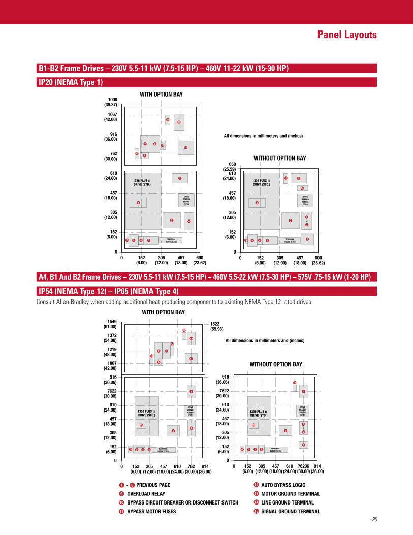
95
Panel Layouts
B1-B2 Frame Drives – 230V 5.5-11 kW (7.5-15 HP) – 460V 11-22 kW (15-30 HP)
IP20 (NEMA Type 1)
00
1000(39.37)
1067(42.00)
916(36.00)
762(30.00)
610(24.00)
457(18.00)
305(12.00)
152(6.00)
152(6.00)
305(12.00)
457(18.00)
600(23.62)
WITH OPTION BAY
5 3
2
4
1
913
14
14
6
7 8 1211
10
DRIVEBRANCHFUSING(STD.)
WITHOUT OPTION BAY
00
650(25.59)
610(24.00)
457(18.00)
305(12.00)
152(6.00)
152(6.00)
305(12.00)
457(18.00)
600(23.62)
5 3 9
2
4
14
1
DRIVEBRANCHFUSING(STD.)
6
7
or
1336 PLUS II DRIVE (STD.)
15 4 15 4
1336 PLUS II DRIVE (STD.)
TERMINAL BLOCK (STD.)
TERMINAL BLOCK (STD.)
All dimensions in millimeters and (inches)
WITHOUT OPTION BAY
152(6.00)
457(18.00)
0 305(12.00)
610(24.00)
WITH OPTION BAY
0762
(30.00)914
(36.00)152
(6.00)457
(18.00)0 305
(12.00)610
(24.00)76236(30.00)
914(36.00)
1522(59.93)
7622(30.00)
610(24.00)
305(12.00)
457(18.00)
152(6.00)
916(36.06)
0
1
DRIVEBRANCHFUSING(STD.)
1336 PLUS II DRIVE (STD.)
DRIVEBRANCHFUSING(STD.)
or
1336 PLUS II DRIVE (STD.)
12
7
119
45
15 15
22
14
13
14
45
7622(30.00)
610(24.00)
305(12.00)
457(18.00)
152(6.00)
916(36.06)
1067(42.00)
1219(48.00)
1372(54.00)
1549(61.00)
1616
All dimensions in millimeters and (inches)
TERMINAL BLOCK (STD.)
TERMINAL BLOCK (STD.)
11
3
8
10
3
6
7
9
6
1 AUTO BYPASS LOGIC
MOTOR GROUND TERMINAL
LINE GROUND TERMINAL
SIGNAL GROUND TERMINAL
PREVIOUS PAGE
OVERLOAD RELAY
BYPASS CIRCUIT BREAKER OR DISCONNECT SWITCH
BYPASS MOTOR FUSES
8
11
12
13
14
15
9
10
-
A4, B1 And B2 Frame Drives – 230V 5.5-11 kW (7.5-15 HP) – 460V 5.5-22 kW (7.5-30 HP) – 575V .75-15 kW (1-20 HP)
IP54 (NEMA Type 12) – IP65 (NEMA Type 4)Consult Allen-Bradley when adding additional heat producing components to existing NEMA Type 12 rated drives.
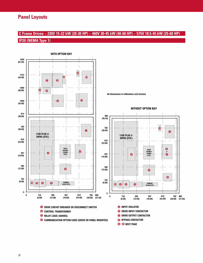
96
Panel Layouts
C Frame Drives – 230V 15-22 kW (20-30 HP) – 460V 30-45 kW (40-60 HP) – 575V 18.5-45 kW (25-60 HP)
IP20 (NEMA Type 1)
WITHOUT OPTION BAY
762(30.00)
900(35.43)
762(30.00)
800(31.50)
610(24.00)
610(24.00)
457(18.00)
457(18.00)
305(12.00)
305(12.00)
152(6.00)
152(6.00)
00
345
1
9
DRIVEBRANCHFUSING(STD.)
WITH OPTION BAY
1336 PLUS DRIVE(STD.)
914(36.00)
1000(42.00)
1550(61.02)
1372(54.00)
1000(48.00)
762(30.00)
762(30.00)
800(31.50)
610(24.00)
610(24.00)
457(18.00)
457(18.00)
305(12.00)
305(12.00)
152(6.00)
152(6.00)
00
7
10
9
8
12
345
1
DRIVEBRANCHFUSING(STD.)
1515
1336 PLUS II DRIVE (STD.) 1336 PLUS II
DRIVE (STD.)
TERMINAL BLOCK (STD.) TERMINAL
BLOCK (STD.)
44
All dimensions in millimeters and (inches)
22
6
7
or
14
6
119
14
13
DRIVE CIRCUIT BREAKER OR DISCONNECT SWITCH
CONTROL TRANSFORMER
RELAY LOGIC (VARIES)
COMMUNICATION OPTION CARD (DRIVE OR PANEL MOUNTED)
1
4
5
6
7
2
3
INPUT ISOLATOR
DRIVE INPUT CONTACTOR
DRIVE OUTPUT CONTACTOR
BYPASS CONTACTOR
NEXT PAGE
8
9 15-
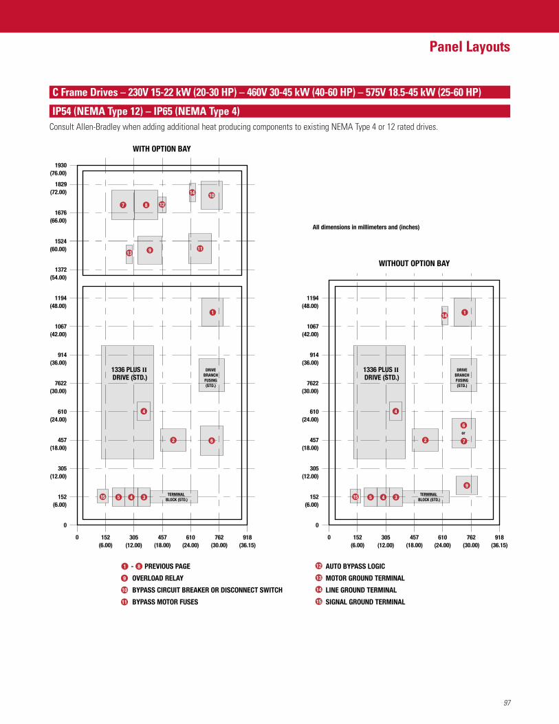
97
Panel Layouts
C Frame Drives – 230V 15-22 kW (20-30 HP) – 460V 30-45 kW (40-60 HP) – 575V 18.5-45 kW (25-60 HP)
IP54 (NEMA Type 12) – IP65 (NEMA Type 4)Consult Allen-Bradley when adding additional heat producing components to existing NEMA Type 4 or 12 rated drives.
WITHOUT OPTION BAY
7622(30.00)
610(24.00)
305(12.00)
457(18.00)
152(6.00)
152(6.00)
457(18.00)
0 305(12.00)
610(24.00)
WITH OPTION BAY
914(36.00)
1067(42.00)
1194(48.00)
0
762(30.00)
918(36.15)
1372(54.00)
1524(60.00)
7 8
9 11
10
1676(66.00)
1829(72.00)
1930(76.00)
7622(30.00)
610(24.00)
305(12.00)
457(18.00)
152(6.00)
914(36.00)
1067(42.00)
1194(48.00)
0
9
1
or
6
1
DRIVEBRANCHFUSING(STD.)
152(6.00)
457(18.00)
0 305(12.00)
610(24.00)
762(30.00)
918(36.15)
1336 PLUS II DRIVE (STD.)
1336 PLUS II DRIVE (STD.)
TERMINAL BLOCK (STD.)
TERMINAL BLOCK (STD.)
DRIVEBRANCHFUSING(STD.)
12
1515 5 4 3
2 2
14
5 4 3
6
4 4
14
13
7
All dimensions in millimeters and (inches)
1 AUTO BYPASS LOGIC
MOTOR GROUND TERMINAL
LINE GROUND TERMINAL
SIGNAL GROUND TERMINAL
PREVIOUS PAGE
OVERLOAD RELAY
BYPASS CIRCUIT BREAKER OR DISCONNECT SWITCH
BYPASS MOTOR FUSES
8
11
12
13
14
15
9
10
-
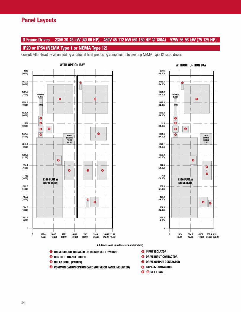
98
Panel Layouts
D Frame Drives – 230V 30-45 kW (40-60 HP) – 460V 45-112 kW (60-150 HP @ 180A) – 575V 56-93 kW (75-125 HP)
IP20 or IP54 (NEMA Type 1 or NEMA Type 12)Consult Allen-Bradley when adding additional heat producing components to existing NEMA Type 12 rated drives.
WITH OPTION BAY
152.4(6.00)
457.2(18.00)
609.6(24.00)
762(30.00)
914.4(36.00)
1066.8(42.00)
1143(45.00)
0
0
304.8(12.00)
152.4(6.00)
304.8(12.00)
457.2(18.00)
609.6(24.00)
762(30.00)
914.4(36.00)
1066.8(42.00)
1219.2(48.00)
1371.6(54.00)
1524(60.00)
1828.8(72.00)
2133.6(84.00)
2286(90.00)
1676.4(66.00)
1981.2(78.00)
13
76 8
1
(STD.)
WITHOUT OPTION BAY
152.4(6.00)
457.2(18.00)
609.6(24.00)
635(25.00)
0
0
304.8(12.00)
152.4(6.00)
304.8(12.00)
457.2(18.00)
609.6(24.00)
762(30.00)
914.4(36.00)
1066.8(42.00)
1219.2(48.00)
1371.6(54.00)
1524(60.00)
1828.8(72.00)
2133.6(84.00)
2286(90.00)
1676.4(66.00)
1981.2(78.00)
6
7
or
9
14 14
1
13
TERMINALBLOCK
TERMINALBLOCK
1336 PLUS II DRIVE (STD.)
1336 PLUS II DRIVE (STD.)
10
11
5
3
4
15
2 5
3
4
15
2
DRIVEBRANCHFUSING(STD.)
DRIVEBRANCHFUSING(STD.)
4 4
(STD.)
9
All dimensions in millimeters and (inches)
DRIVE CIRCUIT BREAKER OR DISCONNECT SWITCH
CONTROL TRANSFORMER
RELAY LOGIC (VARIES)
COMMUNICATION OPTION CARD (DRIVE OR PANEL MOUNTED)
1
4
5
6
7
2
3
INPUT ISOLATOR
DRIVE INPUT CONTACTOR
DRIVE OUTPUT CONTACTOR
BYPASS CONTACTOR
NEXT PAGE
8
9 15-
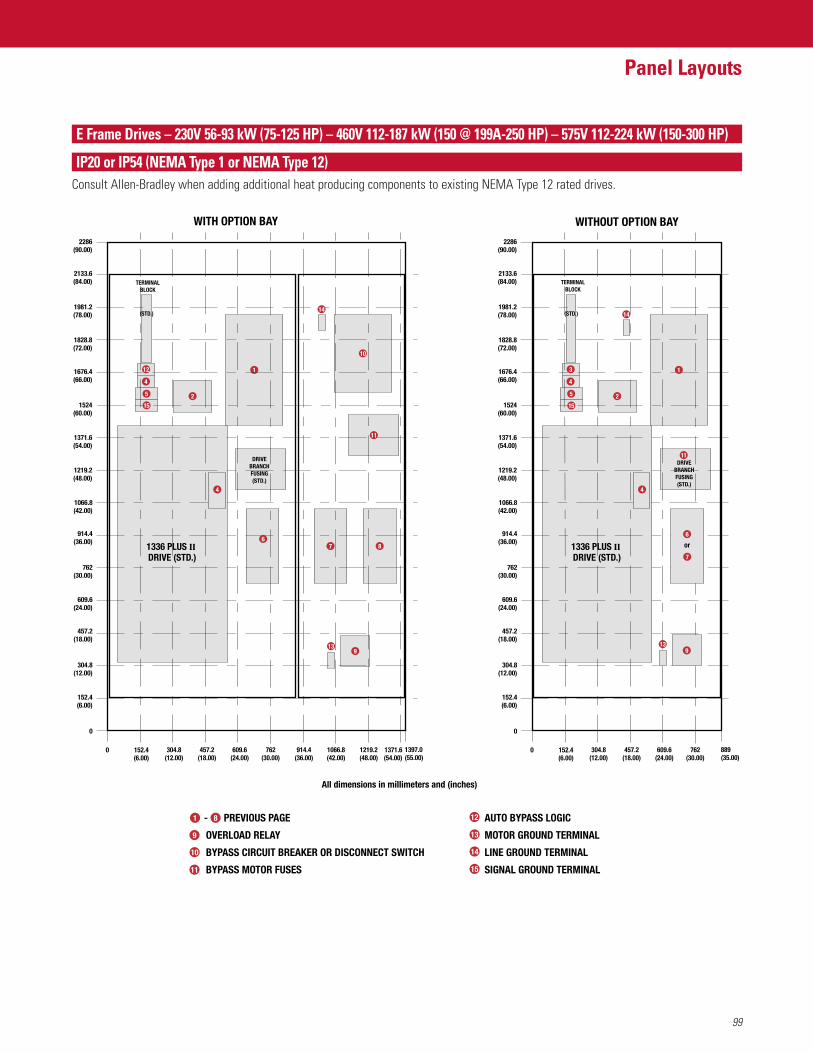
99
Panel Layouts
E Frame Drives – 230V 56-93 kW (75-125 HP) – 460V 112-187 kW (150 @ 199A-250 HP) – 575V 112-224 kW (150-300 HP)
IP20 or IP54 (NEMA Type 1 or NEMA Type 12)Consult Allen-Bradley when adding additional heat producing components to existing NEMA Type 12 rated drives.
152.4(6.00)
457.2(18.00)
609.6(24.00)
762(30.00)
914.4(36.00)
1066.8(42.00)
1219.2(48.00)
0
0
304.8(12.00)
152.4(6.00)
304.8(12.00)
457.2(18.00)
609.6(24.00)
762(30.00)
914.4(36.00)
1066.8(42.00)
1219.2(48.00)
1371.6(54.00)
1524(60.00)
1828.8(72.00)
2133.6(84.00)
2286(90.00)
1676.4(66.00)
1981.2(78.00)
WITH OPTION BAY
1371.6(54.00)
1397.0(55.00)
12
4
5 2
1
10
7 8
913
(STD.)
152.4(6.00)
457.2(18.00)
609.6(24.00)
762(30.00)
0
0
304.8(12.00)
152.4(6.00)
304.8(12.00)
457.2(18.00)
609.6(24.00)
762(30.00)
914.4(36.00)
1066.8(42.00)
1219.2(48.00)
1371.6(54.00)
1524(60.00)
1828.8(72.00)
2133.6(84.00)
2286(90.00)
1676.4(66.00)
1981.2(78.00)
WITHOUT OPTION BAY
889(35.00)
3
4
5 2
11
(STD.) 14
9
6
7
or
13
TERMINALBLOCK
TERMINALBLOCK
1336 PLUS II DRIVE (STD.)
1336 PLUS II DRIVE (STD.)
6
15 15
DRIVEBRANCHFUSING(STD.)
DRIVEBRANCHFUSING(STD.)
4 4
14
11
1
All dimensions in millimeters and (inches)
1 AUTO BYPASS LOGIC
MOTOR GROUND TERMINAL
LINE GROUND TERMINAL
SIGNAL GROUND TERMINAL
PREVIOUS PAGE
OVERLOAD RELAY
BYPASS CIRCUIT BREAKER OR DISCONNECT SWITCH
BYPASS MOTOR FUSES
8
11
12
13
14
15
9
10
-
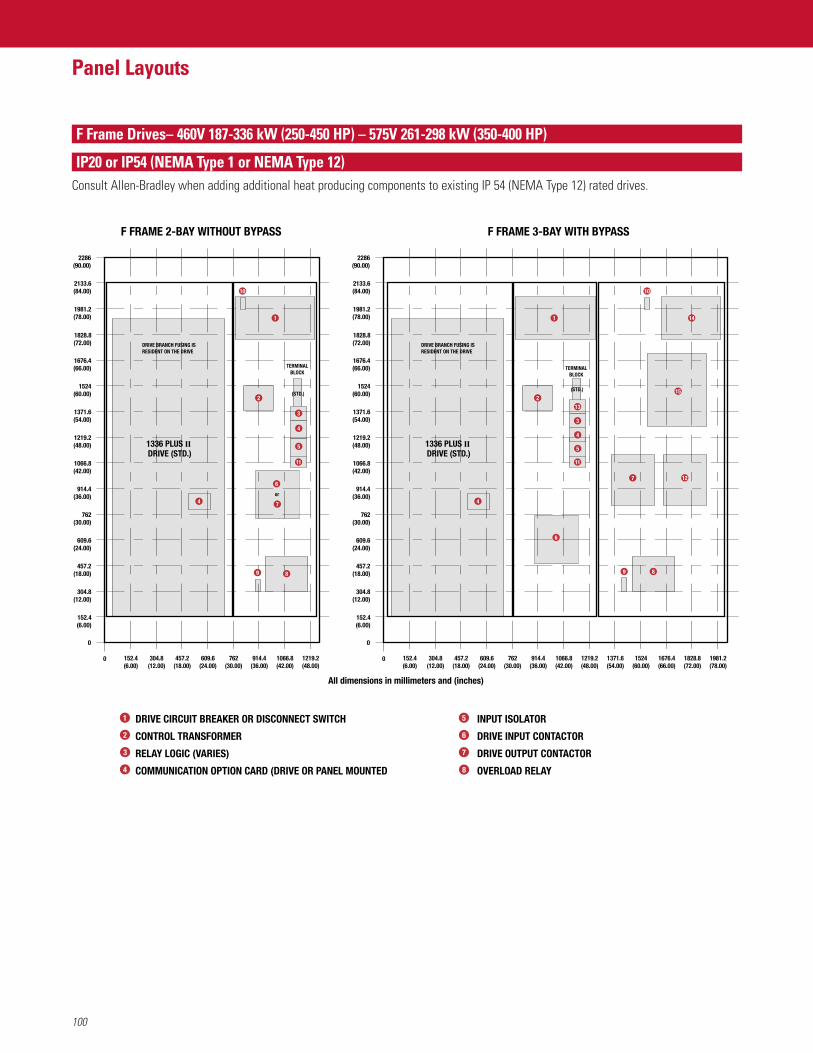
100
Panel Layouts
F Frame Drives– 460V 187-336 kW (250-450 HP) – 575V 261-298 kW (350-400 HP)
IP20 or IP54 (NEMA Type 1 or NEMA Type 12)Consult Allen-Bradley when adding additional heat producing components to existing IP 54 (NEMA Type 12) rated drives.
F FRAME 2-BAY WITHOUT BYPASS
1
10
4
6
7
or
(STD.)
TERMINALBLOCK
152.4(6.00)
457.2(18.00)
609.6(24.00)
762(30.00)
914.4(36.00)
1066.8(42.00)
1219.2(48.00)
0
0
304.8(12.00)
152.4(6.00)
304.8(12.00)
457.2(18.00)
609.6(24.00)
762(30.00)
914.4(36.00)
1066.8(42.00)
1219.2(48.00)
1371.6(54.00)
1524(60.00)
1828.8(72.00)
2133.6(84.00)
2286(90.00)
1676.4(66.00)
1981.2(78.00)
DRIVE BRANCH FUSING IS RESIDENT ON THE DRIVE
All dimensions in millimeters and (inches)
1336 PLUS II DRIVE (STD.)
8
5
4
3
11
9
F FRAME 3-BAY WITH BYPASS
1
10
4
6
7
(STD.)
TERMINALBLOCK
152.4(6.00)
457.2(18.00)
609.6(24.00)
762(30.00)
914.4(36.00)
1066.8(42.00)
1219.2(48.00)
0
0
304.8(12.00)
152.4(6.00)
304.8(12.00)
457.2(18.00)
609.6(24.00)
762(30.00)
914.4(36.00)
1066.8(42.00)
1219.2(48.00)
1371.6(54.00)
1524(60.00)
1828.8(72.00)
2133.6(84.00)
2286(90.00)
1676.4(66.00)
1981.2(78.00)
1371.6(54.00)
1524(60.00)
1676.4(66.00)
1828.8(72.00)
1981.2(78.00)
DRIVE BRANCH FUSING IS RESIDENT ON THE DRIVE
1336 PLUS II DRIVE (STD.)
8
5
4
13
3
11
12
9
14
152 2
DRIVE CIRCUIT BREAKER OR DISCONNECT SWITCH
CONTROL TRANSFORMER
RELAY LOGIC (VARIES)
COMMUNICATION OPTION CARD (DRIVE OR PANEL MOUNTED
INPUT ISOLATOR
DRIVE INPUT CONTACTOR
DRIVE OUTPUT CONTACTOR
OVERLOAD RELAY
1
4
5
6
7
2
3
8
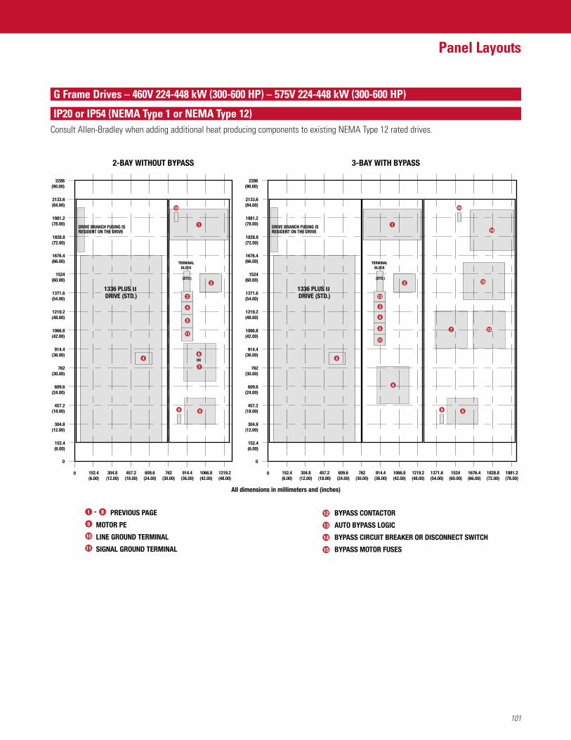
101
Panel Layouts
G Frame Drives – 460V 224-448 kW (300-600 HP) – 575V 224-448 kW (300-600 HP)
IP20 or IP54 (NEMA Type 1 or NEMA Type 12)Consult Allen-Bradley when adding additional heat producing components to existing NEMA Type 12 rated drives.
2
3-BAY WITH BYPASS
152.4(6.00)
457.2(18.00)
609.6(24.00)
762(30.00)
914.4(36.00)
1066.8(42.00)
1219.2(48.00)
0
0
304.8(12.00)
152.4(6.00)
304.8(12.00)
457.2(18.00)
609.6(24.00)
762(30.00)
914.4(36.00)
1066.8(42.00)
1219.2(48.00)
1371.6(54.00)
1524(60.00)
1828.8(72.00)
2133.6(84.00)
2286(90.00)
1676.4(66.00)
1981.2(78.00)
7
8
114
15
4
1371.6(54.00)
1524(60.00)
1828.8(72.00)
1676.4(66.00)
1981.2(78.00)
10
9
5
11
3
4
13
(STD.)
TERMINALBLOCK
1336 PLUS II DRIVE (STD.)
DRIVE BRANCH FUSING IS RESIDENT ON THE DRIVE
2
2-BAY WITHOUT BYPASS
152.4(6.00)
457.2(18.00)
609.6(24.00)
762(30.00)
914.4(36.00)
1066.8(42.00)
1219.2(48.00)
0
0
304.8(12.00)
152.4(6.00)
304.8(12.00)
457.2(18.00)
609.6(24.00)
762(30.00)
914.4(36.00)
1066.8(42.00)
1219.2(48.00)
1371.6(54.00)
1524(60.00)
1828.8(72.00)
2133.6(84.00)
2286(90.00)
1676.4(66.00)
1981.2(78.00)
6
8
1
4
9
5
11
4
3
(STD.)
TERMINALBLOCK
1336 PLUS II DRIVE (STD.)
DRIVE BRANCH FUSING IS RESIDENT ON THE DRIVE
7
OR
10
12
All dimensions in millimeters and (inches)
8 PREVIOUS PAGE
MOTOR PE
LINE GROUND TERMINAL
SIGNAL GROUND TERMINAL
BYPASS CONTACTOR
AUTO BYPASS LOGIC
BYPASS CIRCUIT BREAKER OR DISCONNECT SWITCH
BYPASS MOTOR FUSES
1
11
12
13
14
9
8
10
15
6
-
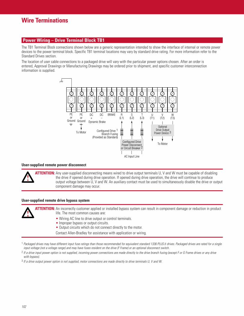
102
Wire Terminations
Power Wiring – Drive Terminal Block TB1The TB1 Terminal Block connections shown below are a generic representation intended to show the interface of internal or remote powerdevices to the power terminal block. Specific TB1 terminal locations may vary by standard drive rating. For more information refer to theStandard Drives section.The location of user cable connections to a packaged drive will vary with the particular power options chosen. After an order is entered, Approval Drawings or Manufacturing Drawings may be ordered prior to shipment, and specific customer interconnectioninformation is supplied.
ATTENTION: Any user-supplied disconnecting means wired to drive output terminals U, V and W must be capable of disablingthe drive if opened during drive operation. If opened during drive operation, the drive will continue to produceoutput voltage between U, V and W. An auxiliary contact must be used to simultaneously disable the drive or outputcomponent damage may occur.
ATTENTION: An incorrectly customer applied or installed bypass system can result in component damage or reduction in productlife. The most common causes are:• Wiring AC line to drive output or control terminals.• Improper bypass or output circuits.• Output circuits which do not connect directly to the motor.Contact Allen-Bradley for assistance with application or wiring.
1 Packaged drives may have different input fuse ratings than those recommended for equivalent standard 1336 PLUS II drives. Packaged drives are rated for a singleinput voltage (not a voltage range) and may have fuses resident on the drive (F Frame) or an optional disconnect switch.
2 If a drive input power option is not supplied, incoming power connections are made directly to the drive branch fusing (except F or G Frame drives or any drive with bypass).
3 If a drive output power option is not supplied, motor connections are made directly to drive terminals U, V and W.
AC Input Line
R(L1)
S(L2)
T(L3)
U(T1)
V(T2)
W(T3)
Configured Drive 1Branch Fusing
(Provided as Standard)
Configured DrivePower Disconnect
or Circuit Breaker 2To Motor
OptionalDrive Output
Power Device 3
PEor
Ground
PEor
Ground
DC+
DC–
Dynamic Brake
To Motor
BRAKE
User-supplied remote drive bypass system
User-supplied remote power disconnect
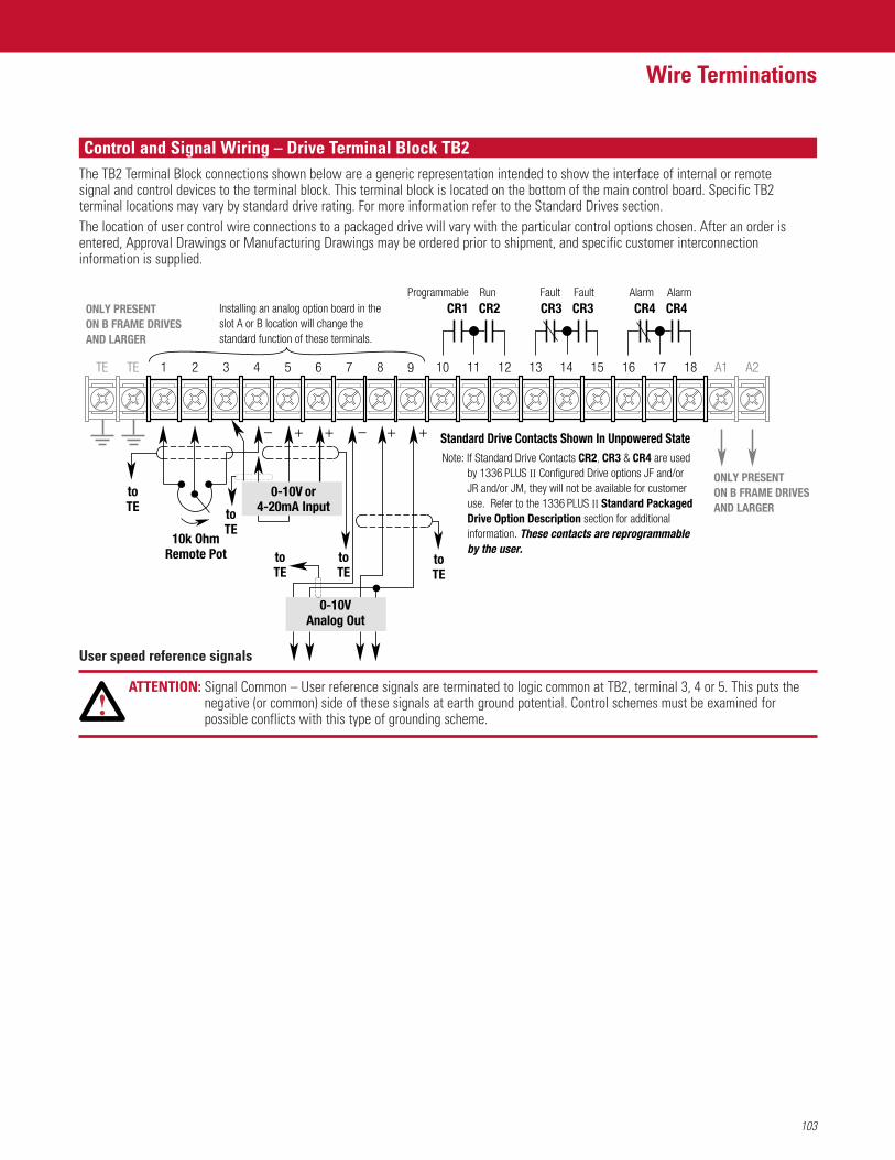
103
Wire Terminations
Control and Signal Wiring – Drive Terminal Block TB2
1
Standard Drive Contacts Shown In Unpowered State
10k OhmRemote Pot
toTE to
TE
toTE
toTE
toTE
ONLY PRESENT ON B FRAME DRIVES AND LARGER
ONLY PRESENTON B FRAME DRIVESAND LARGER
Note: If Standard Drive Contacts CR2, CR3 & CR4 are usedby 1336 PLUS II Configured Drive options JF and/or JR and/or JM, they will not be available for customer use. Refer to the 1336 PLUS II Standard Packaged Drive Option Description section for additional information. These contacts are reprogrammable by the user.
CR2Run
Installing an analog option board in the slot A or B location will change the standard function of these terminals.
Fault AlarmFaultProgrammable
TETE
CR1 CR3CR3 CR4CR4
2 3 4 5 6 9 10 11 12 13 14 15 16 17 18 A1 A287
– +– + + +
Alarm
0-10VAnalog Out
0-10V or4-20mA Input
The TB2 Terminal Block connections shown below are a generic representation intended to show the interface of internal or remote signal and control devices to the terminal block. This terminal block is located on the bottom of the main control board. Specific TB2terminal locations may vary by standard drive rating. For more information refer to the Standard Drives section.The location of user control wire connections to a packaged drive will vary with the particular control options chosen. After an order is entered, Approval Drawings or Manufacturing Drawings may be ordered prior to shipment, and specific customer interconnectioninformation is supplied.
ATTENTION: Signal Common – User reference signals are terminated to logic common at TB2, terminal 3, 4 or 5. This puts thenegative (or common) side of these signals at earth ground potential. Control schemes must be examined forpossible conflicts with this type of grounding scheme.
User speed reference signals
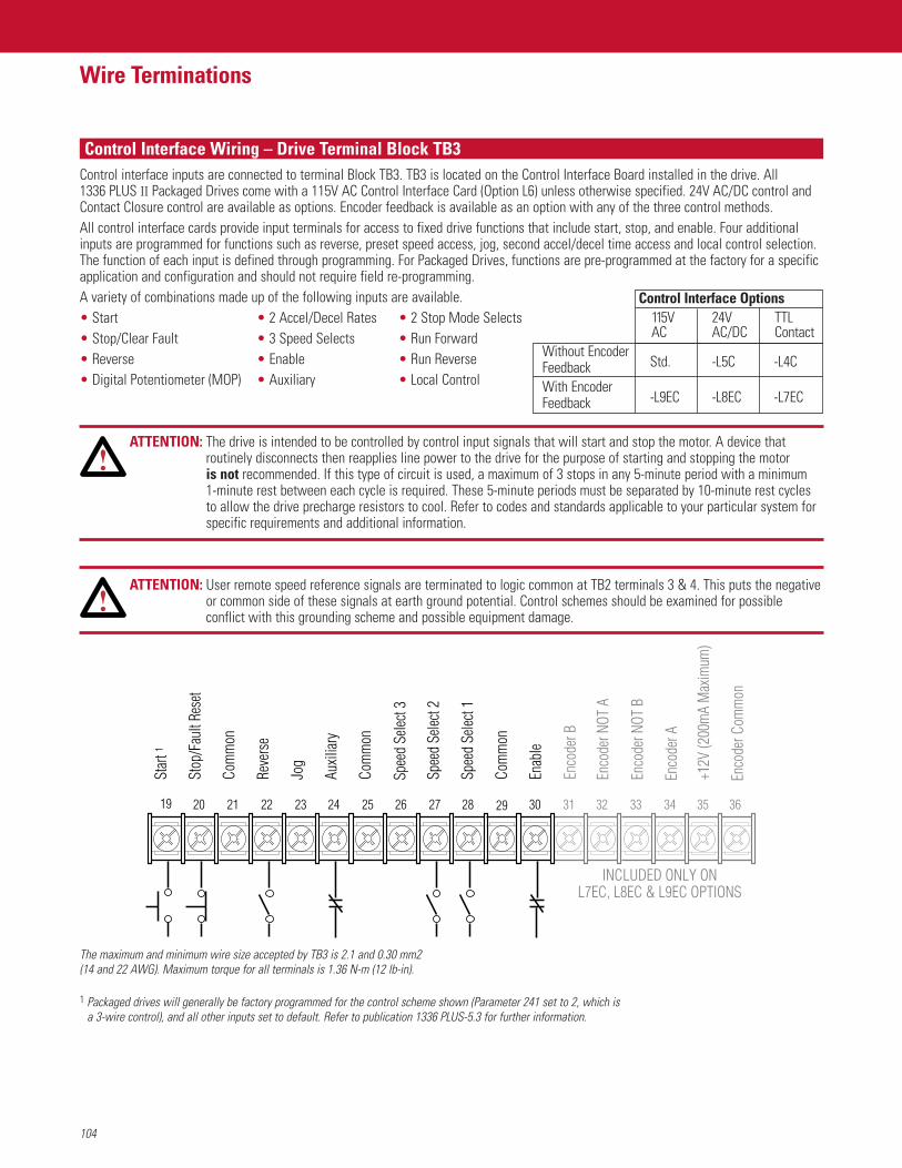
104
Wire Terminations
Control interface inputs are connected to terminal Block TB3. TB3 is located on the Control Interface Board installed in the drive. All 1336 PLUS II Packaged Drives come with a 115V AC Control Interface Card (Option L6) unless otherwise specified. 24V AC/DC control andContact Closure control are available as options. Encoder feedback is available as an option with any of the three control methods.All control interface cards provide input terminals for access to fixed drive functions that include start, stop, and enable. Four additionalinputs are programmed for functions such as reverse, preset speed access, jog, second accel/decel time access and local control selection.The function of each input is defined through programming. For Packaged Drives, functions are pre-programmed at the factory for a specificapplication and configuration and should not require field re-programming.A variety of combinations made up of the following inputs are available.• Start • 2 Accel/Decel Rates • 2 Stop Mode Selects• Stop/Clear Fault • 3 Speed Selects • Run Forward• Reverse • Enable • Run Reverse• Digital Potentiometer (MOP) • Auxiliary • Local Control
ATTENTION: The drive is intended to be controlled by control input signals that will start and stop the motor. A device thatroutinely disconnects then reapplies line power to the drive for the purpose of starting and stopping the motor is not recommended. If this type of circuit is used, a maximum of 3 stops in any 5-minute period with a minimum 1-minute rest between each cycle is required. These 5-minute periods must be separated by 10-minute rest cyclesto allow the drive precharge resistors to cool. Refer to codes and standards applicable to your particular system forspecific requirements and additional information.
ATTENTION: User remote speed reference signals are terminated to logic common at TB2 terminals 3 & 4. This puts the negativeor common side of these signals at earth ground potential. Control schemes should be examined for possibleconflict with this grounding scheme and possible equipment damage.
Control Interface Wiring – Drive Terminal Block TB3
1 Packaged drives will generally be factory programmed for the control scheme shown (Parameter 241 set to 2, which isa 3-wire control), and all other inputs set to default. Refer to publication 1336 PLUS-5.3 for further information.
The maximum and minimum wire size accepted by TB3 is 2.1 and 0.30 mm2 (14 and 22 AWG). Maximum torque for all terminals is 1.36 N-m (12 lb-in).
INCLUDED ONLY ONL7EC, L8EC & L9EC OPTIONS
19
Star
t 1
Jog
Stop
/Fau
lt Re
set
Com
mon
Reve
rse
Auxil
iary
Com
mon
Spee
d Se
lect 2
Spee
d Se
lect 3
Spee
d Se
lect 1
Com
mon
Enco
der B
Enco
der C
omm
on
+12V
(200
mA
Max
imum
)
Enco
der A
Enco
der N
OT B
Enco
der N
OT A
Enab
le
24 25 26 27 28 29 30 31 3332 3534 3623222120
Without EncoderFeedback Std. -L5C -L4C
With EncoderFeedback -L9EC -L8EC -L7EC
Control Interface Options115V 24V TTLAC AC/DC Contact
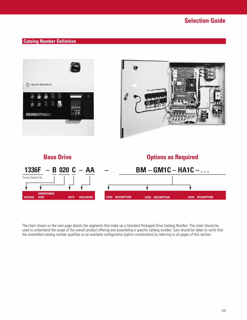
105
Selection Guide
Catalog Number Definition
The chart shown on the next page details the segments that make up a Standard Packaged Drive Catalog Number. This chart should beused to understand the scope of the overall product offering and assembling a specific catalog number. Care should be taken to verify thatthe assembled catalog number qualifies as an available configuration (option combination) by referring to all pages of this section.
1336FProduct Bulletin No.
AAC020 –B BM – GM1C – HA1C – . . .
Base Drive Options as Required
HORSEPOWERVOLTAGE CODE DUTY ENCLOSURE CODE DESCRIPTION
– –
CODE DESCRIPTIONCODE DESCRIPTION
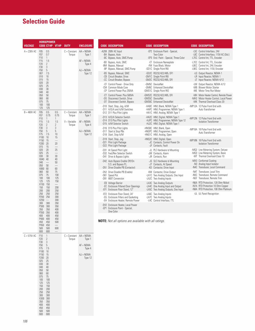
106
Selection Guide
HORSEPOWERVOLTAGE CODE CT HP VT HP DUTY ENCLOSURE
A = 230V AC F05 0.5 C = Constant AA = NEMAF07 0.7 Torque Type 1F10 1F15 1.5 AF = NEMAF20 2 Type 4F30 3F50 5 AJ = NEMA007 7.5 Type 12010 10015 15020 20025 25030 30040 40050 50060 60075 75100 100125 125
B = 460V AC F05 0.5 0.5 C = Constant AA = NEMAF07 0.75 0.75 Torque Type 1F10 1 1F15 1.5 1.5 V = Variable AF = NEMAF20 2 2 Torque Type 4F30 3 3F50 5 5 AJ = NEMAF75 7.5 10 Type 12F100 10 15F150 15 —F200 20 20015 15 —020 20 25025 25 —030 30 30X040 40 40040 — 50050 50 —X060 60 60060 60 75075 75 100100 100 125125 125 150X150 150 —150 150 200200 200 250250 250 250P250 250 300X250 — 300300 300 350P300 300 350350 350 400P350 350 400400 400 450P400 400 450450 450 500P450 450 —500 500 600600 600 —
C = 575V AC F10 1 C = Constant AA = NEMAF20 2 Torque Type 1F30 3F50 5 AF = NEMAF75 7.5 Type 4F100 10F150 15 AJ = NEMAF200 20 Type 12025 25030 30040 40050 50060 60075 75100 100125 125150 150200 200250 250300 300X300 300350 350400 400450 450500 500600 600
NOTE: Not all options are available with all ratings.
CODE DESCRIPTION
-A208 208V AC Input-BA Bypass, Auto-BC Bypass, Auto, SMC-Pump
-BD Bypass, Auto, SMC-BM Bypass, Manual-BP Bypass, Manual, SMC-Pump
-BS Bypass, Manual, SMC-CB Circuit Breaker, Drive-CC Circuit Breaker, Bypass
-CF Control Power - Drive Only-CM Common Mode Core-CP Control Power Plus 250VA
-CT Control Power. Plus 500VA-DS Disconnect Switch, Drive-DT Disconnect Switch, Bypass
-D10 Start, Stop, Jog, A/M-D11 H/O/A and A/M Switches-D12 D11 Plus Pilot Lights
-D13 H/O/A Selector Switch-D14 D13 Plus PIlot Lights-D15 A/M Selector Switch
-D16 D15 Plus Pilot Lights-D17 Start & Stop PBs-D18 Start, Stop A/M
-D19 Start, Stop, Jog-D21 Pilot Light Package-D22 Pilot Light Package
-D31 At Speed Pilot Light-D32 Fwd/Rev Selector Switch-D41 Drive & Bypass Lights
-D42 Auto Bypass Enable Off/OnS.S. and Bypass P.L.
-D51 Drive Disable PB (Contactor)
-D52 Drive Disable PB (Enable)-D61 Speed Pot-D91 800T Conversion
-EB Voltage Barrier-EC Enclosure Filtered Door Openings
-EF1 Enclosure Floor Stand, 12"
-EF2 Enclosure Floor Stand, 24"-EG Enclosure Filters and Gasketing-EH Enclosure Heater, Remote Power
-EH2 Enclosure Heater, Local Power-EP1 Enclosure Paint - Special,
One-Color
CODE DESCRIPTION
-EP2 Enclosure Paint - Special,Two-Color
-EP3 Encl. Paint - Special, Three-Color
-ET Enclosure Nameplate-FM Fuse Block, Motor
-GD1C Single Point RI0
-GD2C RS232/422/485, DF1-GM1C Single Point RI0-GM2C RS232/422/485, DFI
-GM5C DeviceNet-GM6C Enhanced DeviceNet
-GMS1C Single Point RIO
-GMS2C RS232/422/485, DFI-GMS5C DeviceNet-GMS6C Enhanced DeviceNet
-HABC HIM, Blank, NEMA Type 1-HAPC HIM, Programmer, NEMA Type 1-HA1C HIM, Analog, NEMA Type 1
-HA2C HIM, Digital, NEMA Type 1-HJPC HIM, Programmer, NEMA Type 12-HJ2C HIM, Digital, NEMA Type 1
-HNSBC HIM, Blank, Open-HNSPC HIM, Programmer, Open-HNS1C HIM, Analog, Open
-HNS2C HIM, Digital, Open-JC Contacts, Control Power On-JF Contacts, Fault
-JL PLC Hardware & Mounting-JM Contacts, Alarm-JR Contacts, Run
-JS SLC Hardware & Mounting-JT Contacts, At Speed-KD Contactor, Drive Input
-KM Contactor, Drive Output-LA1C Two Analog Outputs, One Input-LA2C Two Analog Inputs
-LA3C Two Analog Outputs-LA4C One Analog Input and Output-LA5C Two Analog Outputs, One Input
-LA6C Two Analog Inputs-LA7C Two Analog Inputs
-L4C Control Interface, TTL
CODE DESCRIPTION
-L5C Control Interface, 24V-L6C Control Interface, 115V AC (Std.)
-L7EC Control Int, TTL, Encoder
-L7EC Control Int, TTL, Encoder-L8EC Control Int, 24V, Encoder-L9EC Control Int, 115V, Encoder
-LQ Output Reactor, NEMA 1-LR Input Reactor, NEMA 1-LT Input Reactor, NEMA 4/12
-LW Output Reactor, NEMA 4/12-MB Blower Motor Starter-ME Motor Time Run Meter
-MH Motor Heater Control, Remote Power-MH2 Motor Heater Control, Local Power
-MK Thermal Overload-Class 20
-MP12A 12 Pulse Front End with Auto Transformer
-MP12N 12 Pulse Front End with Isolation Transformer
-MP18A 18 Pulse Front End with Auto Transformer
-MP18N 18 Pulse Front End with Isolation Transformer
-MQ2 Line Metering System, Deluxe-MQ3 Line Metering System, Basic
-MT Thermal Overload-Class 10
-MX3 Conformal Coating-N3 Analog Input Isolator
-N4C Transducer, Local Command
-N4T Transducer, Local Trim-N5C Transducer, Remote Command-N5T Transducer, Remote Trim
-N6A RTD Protection, 120 Ohm NIckel-N7A RTD Protection 10 Ohm Copper-N8A RTD Protection, 100 Ohm Platinum
-UL UL Panel Recognition
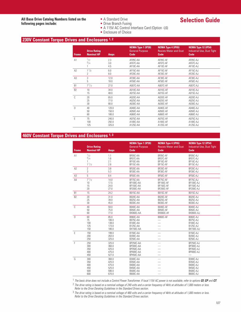
107
Selection Guide
230V Constant Torque Drives and Enclosures 1, 2
460V Constant Torque Drives and Enclosures 1, 3
1 The basic drive does not include a Control Power Transformer. If local 115V AC power is not available, refer to options CF, CP and CT.2 The drive rating is based on a nominal voltage of 240 volts and a carrier frequency of 4kHz at altitudes of 1,000 meters or less.
Refer to the Drive Derating Guidelines in the Standard Drives section.3 The drive rating is based on a nominal voltage of 480 volts and a carrier frequency of 4kHz at altitudes of 1,000 meters or less.
Refer to the Drive Derating Guidelines in the Standard Drives section.
All Base Drive Catalog Numbers listed on the • A Standard Drivefollowing pages include: • Drive Branch Fusing
• A 115V AC Control Interface Card (Option -L6)• Enclosure of Choice
NEMA Type 1 (IP20) NEMA Type 4 (IP65) NEMA Type 12 (IP54)Drive Rating General Purpose Resists Water and Dust Industrial Use, Dust Tight
Frame Nominal HP Amps Code Code Code
A1 1/ 2 2.3 AF05C-AA AF05C-AF AF05C-AJ3/ 4 3.0 AF07C-AA AF07C-AF AF07C-AJ1 4.5 AF10C-AA AF10C-AF AF10C-AJ
A2 1 1/2 6.0 AF15C-AA AF15C-AF AF15C-AJ2 8.0 AF20C-AA AF20C-AF AF20C-AJ
A3 3 12.0 AF30C-AA AF30C-AF AF30C-AJ5 18.0 AF50C-AA AF50C-AF AF50C-AJ
B1 7 1/ 2 27.0 A007C-AA A007C-AF A007C-AJ
B2 10 34.0 A010C-AA A010C-AF A010C-AJ15 48.0 A015C-AA A015C-AF A015C-AJ
C 20 65.0 A020C-AA A020C-AF A020C-AJ25 77.0 A025C-AA A025C-AF A025C-AJ30 80.0 A030C-AA A030C-AF A030C-AJ
D 40 120.0 A040C-AA A040C-AF A040C-AJ50 150.0 A050C-AA A050C-AF A050C-AJ60 180.0 A060C-AA A060C-AF A060C-AJ
E 75 240.0 A075C-AA A075C-AF A075C-AJ100 292.0 A100C-AA A100C-AF A100C-AJ125 325.0 A125C-AA A125C-AF A125C-AJ
NEMA Type 1 (IP20) NEMA Type 4 (IP65) NEMA Type 12 (IP54)Drive Rating General Purpose Resists Water and Dust Industrial Use, Dust Tight
Frame Nominal HP Amps Code Code Code
A1 1/ 2 1.1 BF05C-AA BF05C-AF BF05C-AJ3/ 4 1.6 BF07C-AA BF07C-AF BF07C-AJ1 2.1 BF10C-AA BF10C-AF BF10C-AJ1 1/ 2 2.8 BF15C-AA BF15C-AF BF15C-AJ
A2 2 3.8 BF20C-AA BF20C-AF BF20C-AJ3 5.3 BF30C-AA BF30C-AF BF30C-AJ
A3 5 8.4 BF50C-AA BF50C-AF BF50C-AJA4 7 1/ 2 14.0 BF75C-AA BF75C-AF BF75C-AJ
10 17.5 BF100C-AA BF100C-AF BF100C-AJ15 24.0 BF150C-AA BF150C-AF BF150C-AJ20 27.0 BF200C-AA BF200C-AF BF200C-AJ
B1 15 24.2 B015C-AA B015C-AF B015C-AJB2 20 31.0 B020C-AA B020C-AF B020C-AJ
25 39.0 B025C-AA B025C-AF B025C-AJ30 45.0 B030C-AA B030C-AF B030C-AJ
C 40 59.0 B040C-AA B040C-AF B040C-AJ50 75.0 B050C-AA B050C-AF B050C-AJ60 77.0 BX060C-AA BX060C-AF BX060C-AJ
D 60 85.0 B060C-AA B060C-AF B060C-AJ75 106.0 B075C-AA — B075C-AJ100 138.0 B100C-AA — B100C-AJ125 173.0 B125C-AA — B125C-AJ150 180.0 BX150C-AA — BX150C-AJ
E 150 199.0 B150C-AA — B150C-AJ200 263.0 B200C-AA — B200C-AJ250 325.0 B250C-AA — B250C-AJ
F 250 325.0 BP250C-AA — BP250C-AJ300 360.0 BP300C-AA — BP300C-AJ350 425.0 BP350C-AA — BP350C-AJ400 475.0 BP400C-AA — BP400C-AJ450 527.0 BP450C-AA — —
G 300 360.0 B300C-AA — B300C-AJ350 425.0 B350C-AA — B350C-AJ400 475.0 B400C-AA — B400C-AJ450 525.0 B450C-AA — B450C-AJ500 590.0 B500C-AA — B500C-AJ600 670.0 B600C-AA — B600C-AJ
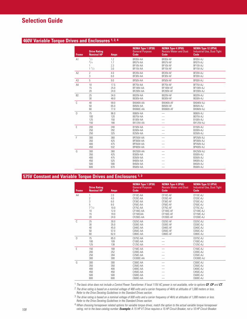
108
Selection Guide
460V Variable Torque Drives and Enclosures 1, 2, 4
1 The basic drive does not include a Control Power Transformer. If local 115V AC power is not available, refer to options CF, CP and CT.2 The drive rating is based on a nominal voltage of 480 volts and a carrier frequency of 4kHz at altitudes of 1,000 meters or less.
Refer to the Drive Derating Guidelines in the Standard Drives section.3 The drive rating is based on a nominal voltage of 600 volts and a carrier frequency of 4kHz at altitudes of 1,000 meters or less.
Refer to the Drive Derating Guidelines in the Standard Drives section.4 When choosing horsepower related options for variable torque drives, match the option to the actual variable torque horsepower
rating, not to the base catalog number. Example: A 15 HP VT Drive requires a 15 HP Circuit Breaker, not a 10 HP Circuit Breaker.
NEMA Type 1 (IP20) NEMA Type 4 (IP65) NEMA Type 12 (IP54)Drive Rating General Purpose Resists Water and Dust Industrial Use, Dust Tight
Frame Nominal HP Amps Code Code Code
A1 1/ 2 1.2 BF05V-AA BF05V-AF BF05V-AJ3/ 4 1.7 BF07V-AA BF07V-AF BF07V-AJ1 2.3 BF10V-AA BF10V-AF BF10V-AJ1 1/ 2 3.0 BF15V-AA BF15V-AF BF15V-AJ
A2 2 4.0 BF20V-AA BF20V-AF BF20V-AJ3 6.0 BF30V-AA BF30V-AF BF30V-AJ
A3 5 9.0 BF50V-AA BF50V-AF BF50V-AJ
A4 10 17.5 BF75V-AA BF75V-AF BF75V-AJ15 25.0 BF100V-AA BF100V-AF BF100V-AJ20 24.0 BF200V-AA BF200V-AF BF200V-AJ
B2 25 34.0 B020V-AA B020V-AF B020V-AJ30 48.0 B030V-AA B030V-AF B030V-AJ
C 40 59.0 BX040V-AA BX040V-AF BX040V-AJ50 65.0 B050V-AA B050V-AF B050V-AJ60 77.0 BX060C-AA BX060V-AF BX060V-AJ
D 75 96.0 B060V-AA — B060V-AJ100 120 B075V-AA — B075V-AJ125 150 B100V-AA — B100V-AJ150 180 BX125V-AA — BX125V-AJ
E 200 240 B150V-AA — B150V-AJ250 292 B200V-AA — B200V-AJ250 325 B250V-AA — B250V-AJ
F 300 360 BP250V-AA — BP250V-AJ350 425 BP300V-AA — BP300V-AJ400 475 BP350V-AA — BP350V-AJ450 532 BP400V-AA — BP400V-AJ
G 300 360 BX250V-AA — BX250V-AJ350 425 B300V-AA — B300V-AJ400 475 B350V-AA — B350V-AJ450 525 B400V-AA — B400V-AJ500 590 B450V-AA — B450V-AJ600 670 B500V-AA — B500V-AJ
NEMA Type 1 (IP20) NEMA Type 4 (IP65) NEMA Type 12 (IP54)Drive Rating General Purpose Resists Water and Dust Industrial Use, Dust Tight
Frame Nominal HP Amps Code Code Code
A4 1 2.0 CF10C-AA CF10C-AF CF10C-AJ2 4.0 CF20C-AA CF20C-AF CF20C-AJ3 6.0 CF30C-AA CF30C-AF CF30C-AJ5 8.0 CF50C-AA CF50C-AF CF50C-AJ7 1/ 2 10.0 CF75C-AA CF75C-AF CF75C-AJ10 12.0 CF100C-AA CF100C-AF CF100C-AJ15 19.0 CF150CAA CF150C-AF CF150C-AJ20 24.0 CF200C-AA CF200C-AF CF200C-AJ
C 25 30.0 C025C-AA C025C-AF C025C-AJ30 35.0 C030C-AA C030C-AF C030C-AJ40 45.0 C040C-AA C040C-AF C040C-AJ50 57.0 C050C-AA C050C-AF C050C-AJ60 62.0 C060C-AA C060C-AF C060C-AJ
D 75 85.0 C075C-AA — C075C-AJ100 109 C100C-AA — C100C-AJ125 138 C125C-AA — C125C-AJ
E 150 168 C150C-AA — C150C-AJ200 252 C200C-AA — C200C-AJ250 284 C250C-AA — C250C-AJ300 300 CX300C-AA — CX300C-AJ
G 300 300 C300C-AA — C300C-AJ350 350 C350C-AA — C350C-AJ400 400 C400C-AA — C400C-AJ450 450 C450C-AA — C450C-AJ500 500 C500C-AA — C500C-AJ600 600 C600C-AA — C600C-AJ
575V Constant and Variable Torque Drives and Enclosures 1, 3
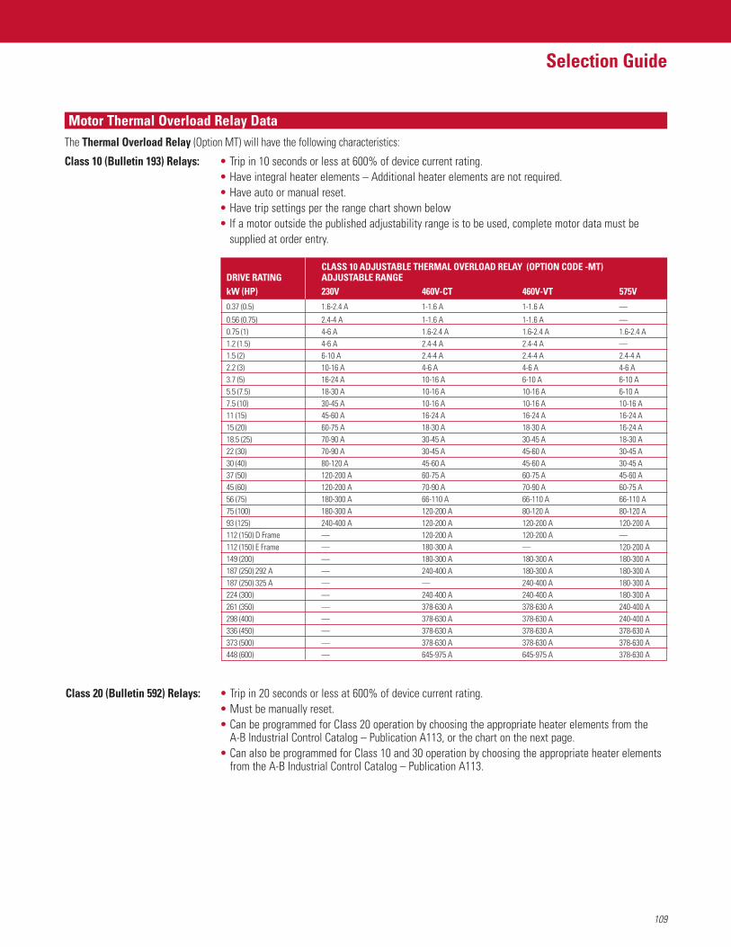
109
Selection Guide
Motor Thermal Overload Relay DataThe Thermal Overload Relay (Option MT) will have the following characteristics:
Class 10 (Bulletin 193) Relays: • Trip in 10 seconds or less at 600% of device current rating.• Have integral heater elements – Additional heater elements are not required.• Have auto or manual reset.• Have trip settings per the range chart shown below• If a motor outside the published adjustability range is to be used, complete motor data must be
supplied at order entry.
Class 20 (Bulletin 592) Relays: • Trip in 20 seconds or less at 600% of device current rating.• Must be manually reset.• Can be programmed for Class 20 operation by choosing the appropriate heater elements from the
A-B Industrial Control Catalog – Publication A113, or the chart on the next page.• Can also be programmed for Class 10 and 30 operation by choosing the appropriate heater elements
from the A-B Industrial Control Catalog – Publication A113.
CLASS 10 ADJUSTABLE THERMAL OVERLOAD RELAY (OPTION CODE -MT)DRIVE RATING ADJUSTABLE RANGEkW (HP) 230V 460V-CT 460V-VT 575V
0.37 (0.5) 1.6-2.4 A 1-1.6 A 1-1.6 A —
0.56 (0.75) 2.4-4 A 1-1.6 A 1-1.6 A —0.75 (1) 4-6 A 1.6-2.4 A 1.6-2.4 A 1.6-2.4 A1.2 (1.5) 4-6 A 2.4-4 A 2.4-4 A —1.5 (2) 6-10 A 2.4-4 A 2.4-4 A 2.4-4 A2.2 (3) 10-16 A 4-6 A 4-6 A 4-6 A3.7 (5) 16-24 A 10-16 A 6-10 A 6-10 A5.5 (7.5) 18-30 A 10-16 A 10-16 A 6-10 A7.5 (10) 30-45 A 10-16 A 10-16 A 10-16 A11 (15) 45-60 A 16-24 A 16-24 A 16-24 A15 (20) 60-75 A 18-30 A 18-30 A 16-24 A18.5 (25) 70-90 A 30-45 A 30-45 A 18-30 A22 (30) 70-90 A 30-45 A 45-60 A 30-45 A30 (40) 80-120 A 45-60 A 45-60 A 30-45 A37 (50) 120-200 A 60-75 A 60-75 A 45-60 A45 (60) 120-200 A 70-90 A 70-90 A 60-75 A56 (75) 180-300 A 66-110 A 66-110 A 66-110 A75 (100) 180-300 A 120-200 A 80-120 A 80-120 A93 (125) 240-400 A 120-200 A 120-200 A 120-200 A112 (150) D Frame — 120-200 A 120-200 A —112 (150) E Frame — 180-300 A — 120-200 A149 (200) — 180-300 A 180-300 A 180-300 A187 (250) 292 A — 240-400 A 180-300 A 180-300 A187 (250) 325 A — — 240-400 A 180-300 A224 (300) — 240-400 A 240-400 A 180-300 A261 (350) — 378-630 A 378-630 A 240-400 A298 (400) — 378-630 A 378-630 A 240-400 A336 (450) — 378-630 A 378-630 A 378-630 A373 (500) — 378-630 A 378-630 A 378-630 A448 (600) — 645-975 A 645-975 A 378-630 A
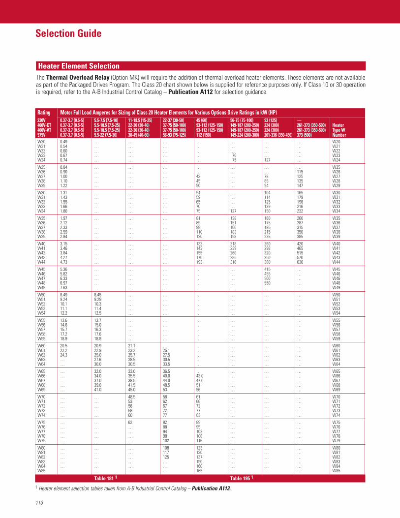
110
Heater Element SelectionThe Thermal Overload Relay (Option MK) will require the addition of thermal overload heater elements. These elements are not availableas part of the Packaged Drives Program. The Class 20 chart shown below is supplied for reference purposes only. If Class 10 or 30 operationis required, refer to the A-B Industrial Control Catalog – Publication A112 for selection guidance.
Selection Guide
Rating Motor Full Load Amperes for Sizing of Class 20 Heater Elements for Various Options Drive Ratings in kW (HP)230V 0.37-3.7 (0.5-5) 5.5-7.5 (7.5-10) 11-18.5 (15-25) 22-37 (30-50) 45 (60) 56-75 (75-100) 93 (125) —460V-CT 0.37-3.7 (0.5-5) 5.5-18.5 (7.5-25) 22-30 (30-40) 37-75 (50-100) 93-112 (125-150) 149-187 (200-250) 224 (300) 261-373 (350-500) Heater460V-VT 0.37-3.7 (0.5-5) 5.5-18.5 (7.5-25) 22-30 (30-40) 37-75 (50-100) 93-112 (125-150) 149-187 (200-250) 224 (300) 261-373 (350-500) Type W575V 0.37-3.7 (0.5-5) 5.5-22 (7.5-30) 30-45 (40-60) 56-93 (75-125) 112 (150) 149-224 (200-300) 261-336 (350-450) 373 (500) NumberW20 0.49 … … … … … … … W20W21 0.54 … … … … … … … W21W22 0.60 … … … … … … … W22W23 0.67 … … … … 70 … … W23W24 0.74 … … … … 75 127 … W24
W25 0.84 … … … … … … … W25W26 0.90 … … … … … … 115 W26W27 1.00 … … … 43 … 78 125 W27W28 1.10 … … … 45 … 85 135 W28W29 1.22 … … … 50 … 94 147 W29
W30 1.31 … … … 54 … 104 165 W30W31 1.43 … … … 59 … 114 179 W31W32 1.55 … … … 65 … 125 196 W32W33 1.66 … … … 70 … 139 216 W33W34 1.80 … … … 75 127 150 232 W34
W35 1.97 … … … 81 138 160 260 W35W36 2.12 … … … 89 151 175 287 W36W37 2.33 … … … 98 166 195 315 W37W38 2.59 … … … 110 183 215 350 W38W39 2.84 … … … 120 198 235 385 W39
W40 3.15 … … … 132 218 260 420 W40W41 3.46 … … … 143 239 298 465 W41W42 3.84 … … … 155 260 320 515 W42W43 4.27 … … … 170 285 350 570 W43W44 4.73 … … … 193 310 380 630 W44
W45 5.36 … … … … … 415 … W45W46 5.82 … … … … … 455 … W46W47 6.33 … … … … … 500 … W46W48 6.97 … … … … … 550 … W48W49 7.63 … … … … … … … W49
W50 8.49 8.45 … … … … … … W50W51 9.24 9.29 … … … … … … W51W52 10.1 10.3 … … … … … … W52W53 11.1 11.4 … … … … … … W53W54 12.2 12.5 … … … … … … W54
W55 13.6 13.7 … … … … … … W55W56 14.6 15.0 … … … … … … W56W57 15.7 16.3 … … … … … … W57W58 17.2 17.6 … … … … … … W58W59 18.9 18.9 … … … … … … W59
W60 20.5 20.9 21.1 … … … … … W60W61 22.2 22.9 23.2 25.1 … … … … W61W62 24.3 25.0 25.7 27.5 … … … … W62W63 … 27.6 28.5 30.5 … … … … W63W64 … 30.0 30.5 33.5 … … … … W64
W65 … 32.0 33.0 36.5 … … … … W65W66 … 34.0 35.5 40.0 43.0 … … … W66W67 … 37.0 38.5 44.0 47.0 … … … W67W68 … 39.0 41.5 48.5 51 … … … W68W69 … 41.0 45.0 53 56 … … … W69
W70 … … 48.5 58 61 … … … W70W71 … … 53 62 66 … … … W71W72 … … 56 67 72 … … … W72W73 … … 58 72 77 … … … W73W74 … … 60 77 83 … … … W74
W75 … … 62 82 89 … … … W75W76 … … … 88 95 … … … W76W77 … … … 94 102 … … … W77W78 … … … 98 108 … … … W78W79 … … … 102 116 … … … W79
W80 … … … 108 123 … … … W80W81 … … … 117 130 … … … W81W82 … … … 125 137 … … … W82W83 … … … … 150 … … … W83W84 … … … … 160 … … … W84W85 … … … … 165 … … … W85
Table 181 1 Table 195 1
1 Heater element selection tables taken from A-B Industrial Control Catalog – Publication A113.
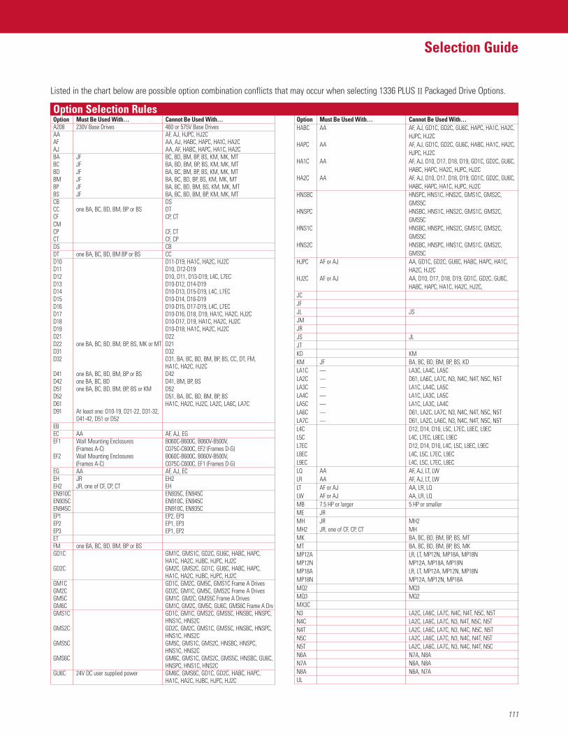
111
Selection Guide460V Variable Torque Drives and Enclosures 1, 2, 4
Option Selection RulesOption Must Be Used With… Cannot Be Used With…A208 230V Base Drives 460 or 575V Base DrivesAA AF, AJ, HJPC, HJ2CAF AA, AJ, HABC, HAPC, HA1C, HA2CAJ AA, AF, HABC, HAPC, HA1C, HA2CBA JF BC, BD, BM, BP, BS, KM, MK, MTBC JF BA, BD, BM, BP, BS, KM, MK, MTBD JF BA, BC, BM, BP, BS, KM, MK, MTBM JF BA, BC, BD, BP, BS, KM, MK, MTBP JF BA, BC, BD, BM, BS, KM, MK, MTBS JF BA, BC, BD, BM, BP, KM, MK, MTCB DSCC one BA, BC, BD, BM, BP or BS DTCF CP, CTCMCP CF, CTCT CF, CPDS CBDT one BA, BC, BD, BM BP or BS CCD10 D11-D19, HA1C, HA2C, HJ2CD11 D10, D12-D19D12 D10, D11, D13-D19, L4C, L7ECD13 D10-D12, D14-D19D14 D10-D13, D15-D19, L4C, L7ECD15 D10-D14, D16-D19D16 D10-D15, D17-D19, L4C, L7ECD17 D10-D16, D18, D19, HA1C, HA2C, HJ2CD18 D10-D17, D19, HA1C, HA2C, HJ2CD19 D10-D18, HA1C, HA2C, HJ2CD21 D22D22 one BA, BC, BD, BM, BP, BS, MK or MT D21D31 D32D32 D31, BA, BC, BD, BM, BP, BS, CC, DT, FM,
HA1C, HA2C, HJ2CD41 one BA, BC, BD, BM, BP or BS D42D42 one BA, BC, BD D41, BM, BP, BSD51 one BA, BC, BD, BM, BP, BS or KM D52D52 D51, BA, BC, BD, BM, BP, BSD61 HA1C, HA2C, HJ2C, LA2C, LA6C, LA7CD91 At least one: D10-19, D21-22, D31-32,
D41-42, D51 or D52EBEC AA AF, AJ, EGEF1 Wall Mounting Enclosures B060C-B600C, B060V-B500V,
(Frames A-C) C075C-C600C, EF2 (Frames D-G)EF2 Wall Mounting Enclosures B060C-B600C, B060V-B500V,
(Frames A-C) C075C-C600C, EF1 (Frames D-G)EG AA AF, AJ, ECEH JR EH2EH2 JR, one of CF, CP, CT EHEN910C EN935C, EN945CEN935C EN910C, EN945CEN945C EN910C, EN935CEP1 EP2, EP3EP2 EP1, EP3EP3 EP1, EP2ETFM one BA, BC, BD, BM, BP or BSGD1C GM1C, GMS1C, GD2C, GU6C, HABC, HAPC,
HA1C, HA2C, HJBC, HJPC, HJ2CGD2C GM2C, GMS2C, GD1C, GU6C, HABC, HAPC,
HA1C, HA2C, HJBC, HJPC, HJ2CGM1C GD1C, GM2C, GM5C, GMS1C Frame A DrivesGM2C GD2C, GM1C, GM5C, GMS2C Frame A DrivesGM5C GM1C. GM2C, GMS5C Frame A DrivesGM6C GM1C, GM2C, GM5C, GU6C, GMS6C Frame A DrvGMS1C GD1C, GM1C, GMS2C, GMS5C, HNSBC, HNSPC,
HNS1C, HNS2CGMS2C GD2C, GM2C, GMS1C, GMS5C, HNSBC, HNSPC,
HNS1C, HNS2CGMS5C GM5C, GMS1C, GMS2C, HNSBC, HNSPC,
HNS1C, HNS2CGMS6C GM6C, GMS1C, GMS2C, GMS5C, HNSBC, GU6C,
HNSPC, HNS1C, HNS2CGU6C 24V DC user supplied power GM6C, GMS6C, GD1C, GD2C, HABC, HAPC,
HA1C, HA2C, HJBC, HJPC, HJ2C
Option Must Be Used With… Cannot Be Used With…HABC AA AF, AJ, GD1C, GD2C, GU6C, HAPC, HA1C, HA2C,
HJPC, HJ2CHAPC AA AF, AJ, GD1C, GD2C, GU6C, HABC, HA1C, HA2C,
HJPC, HJ2CHA1C AA AF, AJ, D10, D17, D18, D19, GD1C, GD2C, GU6C,
HABC, HAPC, HA2C, HJPC, HJ2CHA2C AA AF, AJ, D10, D17, D18, D19, GD1C, GD2C, GU6C,
HABC, HAPC, HA1C, HJPC, HJ2CHNSBC HNSPC, HNS1C, HNS2C, GMS1C, GMS2C,
GMS5CHNSPC HNSBC, HNS1C, HNS2C, GMS1C, GMS2C,
GMS5CHNS1C HNSBC, HNSPC, HNS2C, GMS1C, GMS2C,
GMS5CHNS2C HNSBC, HNSPC, HNS1C, GMS1C, GMS2C,
GMS5CHJPC AF or AJ AA, GD1C, GD2C, GU6C, HABC, HAPC, HA1C,
HA2C, HJ2CHJ2C AF or AJ AA, D10, D17, D18, D19, GD1C, GD2C, GU6C,
HABC, HAPC, HA1C, HA2C, HJ2C, JCJFJL JSJMJRJS JLJTKD KMKM JF BA, BC, BD, BM, BP, BS, KDLA1C — LA3C, LA4C, LA5CLA2C — D61, LA6C, LA7C, N3, N4C, N4T, N5C, N5TLA3C — LA1C, LA4C, LA5CLA4C — LA1C, LA3C, LA5CLA5C — LA1C, LA3C, LA4CLA6C — D61, LA2C, LA7C, N3, N4C, N4T, N5C, N5TLA7C — D61, LA2C, LA6C, N3, N4C, N4T, N5C, N5TL4C D12, D14, D16, L5C, L7EC, L8EC, L9EC L5C L4C, L7EC, L8EC, L9ECL7EC D12, D14, D16, L4C, L5C, L8EC, L9EC L8EC L4C, L5C, L7EC, L9ECL9EC L4C, L5C, L7EC, L8ECLQ AA AF, AJ, LT, LWLR AA AF, AJ, LT, LWLT AF or AJ AA, LR, LQLW AF or AJ AA, LR, LQMB 7.5 HP or larger 5 HP or smallerME JRMH JR MH2MH2 JR, one of CF, CP, CT MHMK BA, BC, BD, BM, BP, BS, MTMT BA, BC, BD, BM, BP, BS, MKMP12A LR, LT, MP12N, MP18A, MP18NMP12N MP12A, MP18A, MP18NMP18A LR, LT, MP12A, MP12N, MP18NMP18N MP12A, MP12N, MP18AMQ2 MQ3MQ3 MQ2MX3CN3 LA2C, LA6C, LA7C, N4C, N4T, N5C, N5TN4C LA2C, LA6C, LA7C, N3, N4T, N5C, N5T N4T LA2C, LA6C, LA7C, N3, N4C, N5C, N5TN5C LA2C, LA6C, LA7C, N3, N4C, N4T, N5TN5T LA2C, LA6C, LA7C, N3, N4C, N4T, N5CN6A N7A, N8AN7A N6A, N8AN8A N6A, N7AUL
Listed in the chart below are possible option combination conflicts that may occur when selecting 1336 PLUS II Packaged Drive Options.
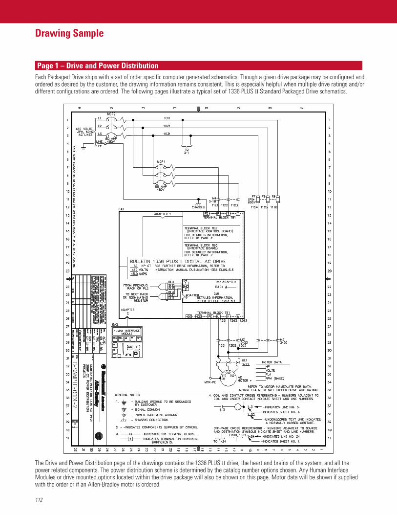
112
Drawing Sample
Page 1 – Drive and Power DistributionEach Packaged Drive ships with a set of order specific computer generated schematics. Though a given drive package may be configured andordered as desired by the customer, the drawing information remains consistent. This is especially helpful when multiple drive ratings and/ordifferent configurations are ordered. The following pages illustrate a typical set of 1336 PLUS II Standard Packaged Drive schematics.
The Drive and Power Distribution page of the drawings contains the 1336 PLUS II drive, the heart and brains of the system, and all thepower related components. The power distribution scheme is determined by the catalog number options chosen. Any Human InterfaceModules or drive mounted options located within the drive package will also be shown on this page. Motor data will be shown if suppliedwith the order or if an Allen-Bradley motor is ordered.
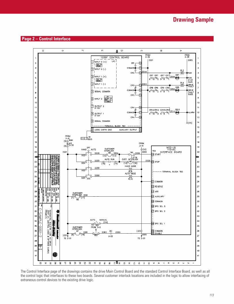
113
Drawing Sample
Page 2 – Control Interface
The Control Interface page of the drawings contains the drive Main Control Board and the standard Control Interface Board, as well as allthe control logic that interfaces to these two boards. Several customer interlock locations are included in the logic to allow interfacing ofextraneous control devices to the existing drive logic.
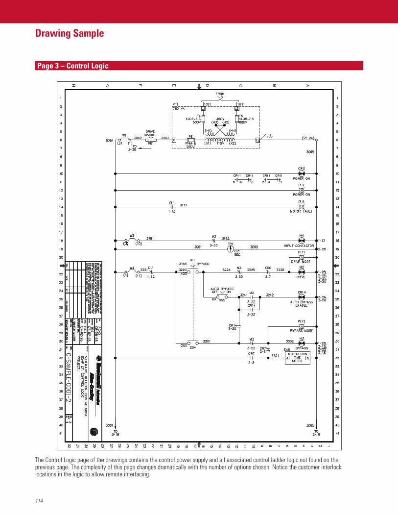
114
Drawing Sample
Page 3 – Control Logic
The Control Logic page of the drawings contains the control power supply and all associated control ladder logic not found on theprevious page. The complexity of this page changes dramatically with the number of options chosen. Notice the customer interlocklocations in the logic to allow remote interfacing.
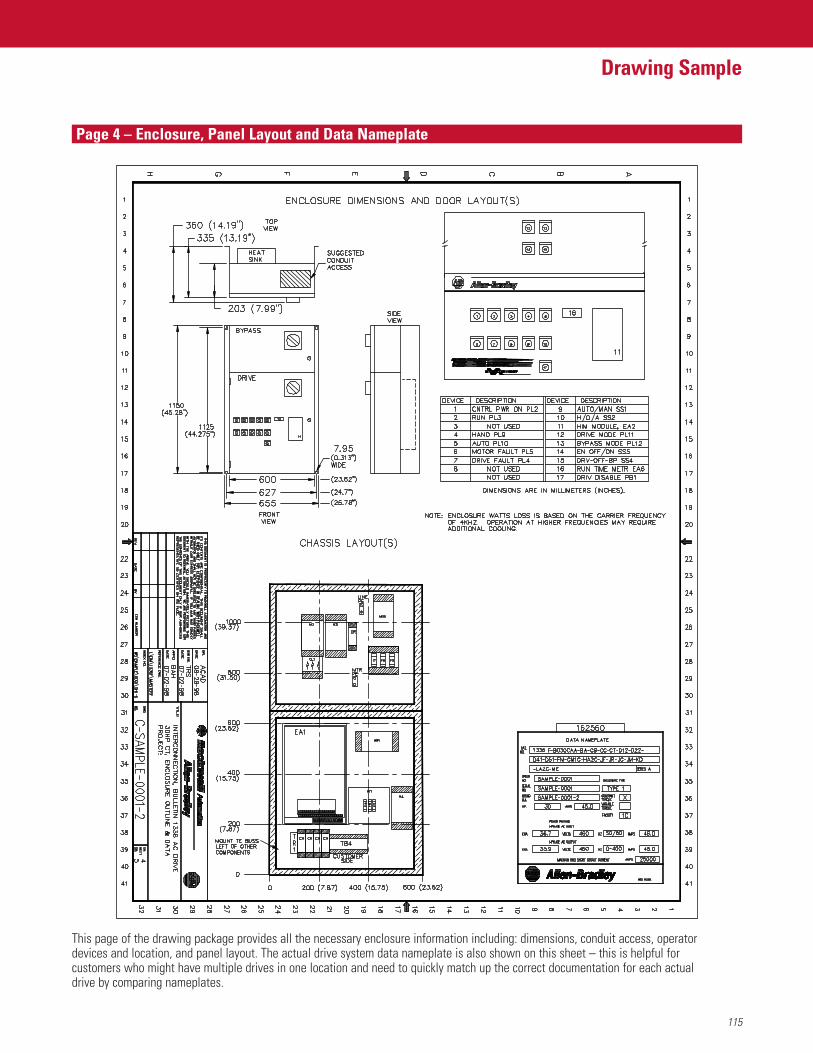
115
Drawing Sample
Page 4 – Enclosure, Panel Layout and Data Nameplate
This page of the drawing package provides all the necessary enclosure information including: dimensions, conduit access, operatordevices and location, and panel layout. The actual drive system data nameplate is also shown on this sheet – this is helpful forcustomers who might have multiple drives in one location and need to quickly match up the correct documentation for each actualdrive by comparing nameplates.
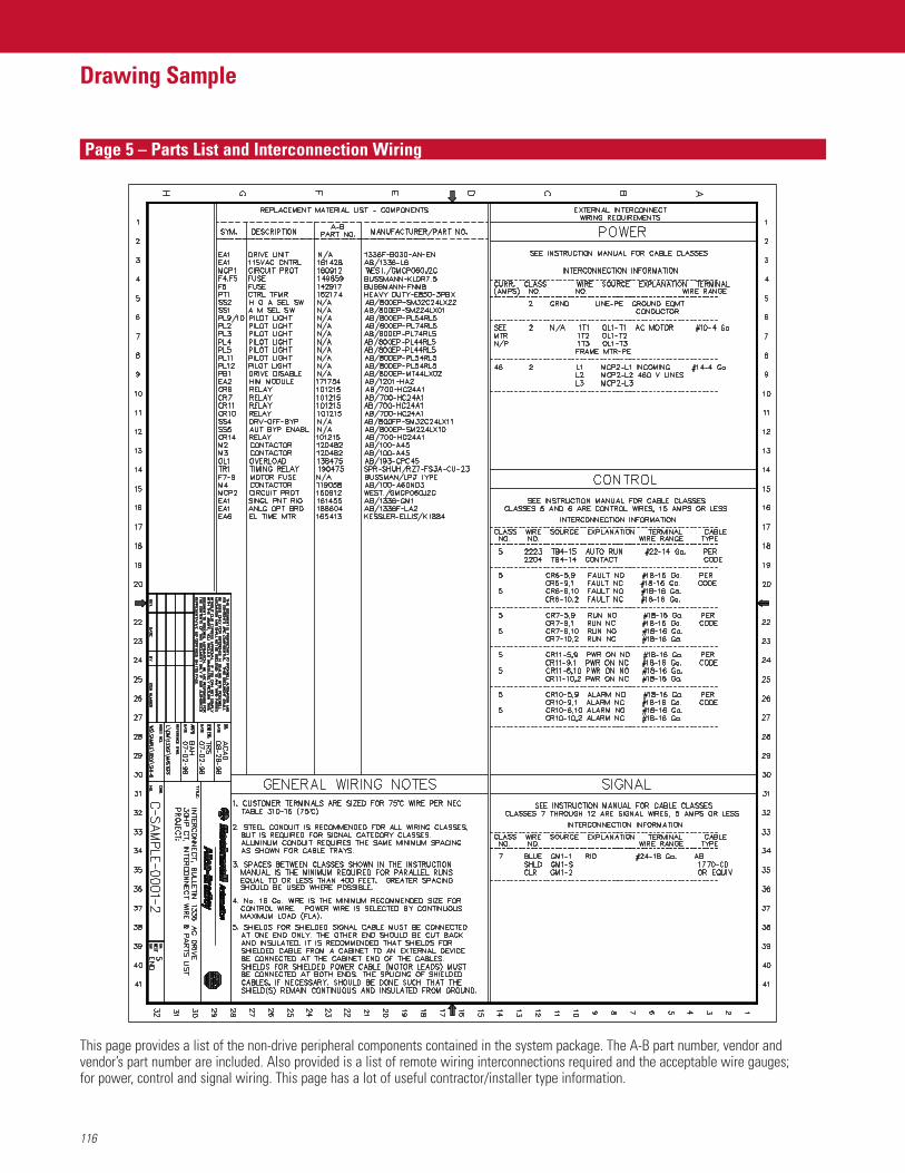
116
Drawing Sample
Page 5 – Parts List and Interconnection Wiring
This page provides a list of the non-drive peripheral components contained in the system package. The A-B part number, vendor andvendor’s part number are included. Also provided is a list of remote wiring interconnections required and the acceptable wire gauges;for power, control and signal wiring. This page has a lot of useful contractor/installer type information.
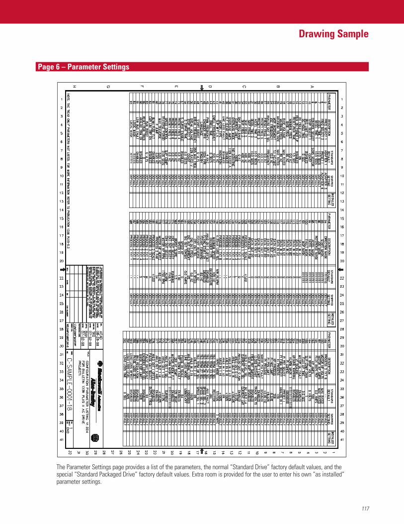
117
Drawing Sample
Page 6 – Parameter Settings
The Parameter Settings page provides a list of the parameters, the normal “Standard Drive” factory default values, and thespecial “Standard Packaged Drive” factory default values. Extra room is provided for the user to enter his own “as installed”parameter settings.
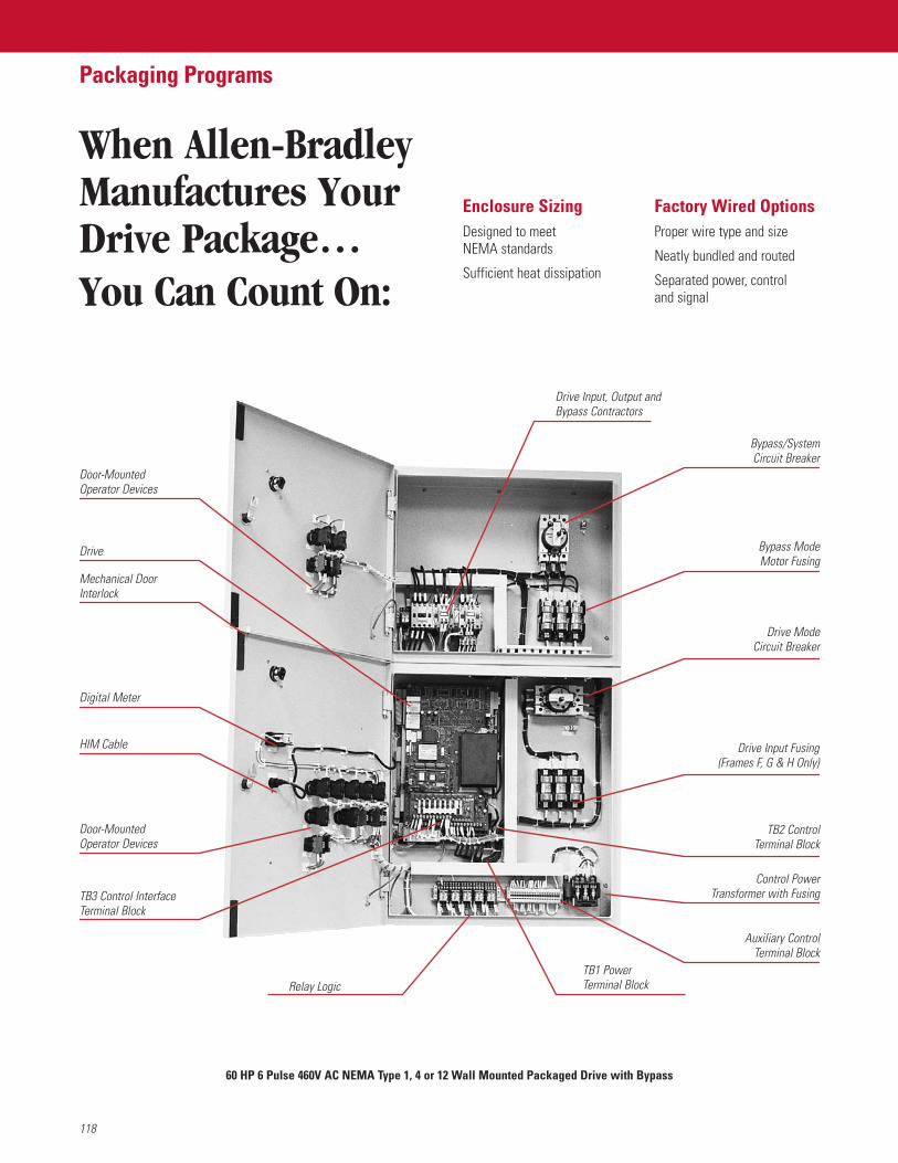
When Allen-BradleyManufactures YourDrive Package…You Can Count On:
118
Packaging Programs
Enclosure SizingDesigned to meetNEMA standards
Sufficient heat dissipation
Factory Wired OptionsProper wire type and size
Neatly bundled and routed
Separated power, control and signal
Door-MountedOperator Devices
Drive
Mechanical DoorInterlock
Digital Meter
HIM Cable
Door-MountedOperator Devices
TB3 Control InterfaceTerminal Block
Relay LogicTB1 PowerTerminal Block
Auxiliary ControlTerminal Block
Control PowerTransformer with Fusing
Drive Input Fusing(Frames F, G & H Only)
TB2 ControlTerminal Block
Drive ModeCircuit Breaker
Bypass ModeMotor Fusing
Bypass/SystemCircuit Breaker
Drive Input, Output and Bypass Contractors
60 HP 6 Pulse 460V AC NEMA Type 1, 4 or 12 Wall Mounted Packaged Drive with Bypass
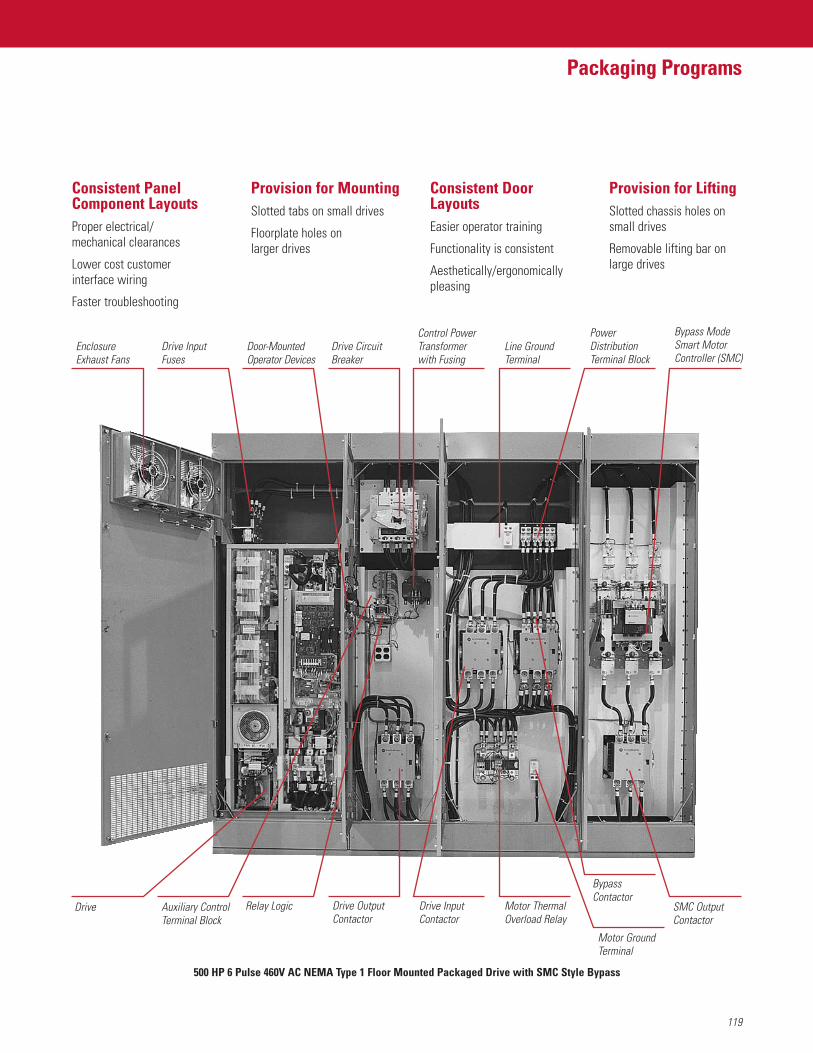
119
Packaging Programs
500 HP 6 Pulse 460V AC NEMA Type 1 Floor Mounted Packaged Drive with SMC Style Bypass
Consistent PanelComponent LayoutsProper electrical/mechanical clearances
Lower cost customerinterface wiring
Faster troubleshooting
Provision for MountingSlotted tabs on small drives
Floorplate holes on larger drives
Consistent DoorLayoutsEasier operator training
Functionality is consistent
Aesthetically/ergonomicallypleasing
Provision for LiftingSlotted chassis holes on small drives
Removable lifting bar onlarge drives
EnclosureExhaust Fans
Drive InputFuses
Door-MountedOperator Devices
Drive CircuitBreaker
Control PowerTransformerwith Fusing
Line GroundTerminal
PowerDistributionTerminal Block
Bypass ModeSmart MotorController (SMC)
Drive Auxiliary ControlTerminal Block
Relay Logic Drive OutputContactor
Drive InputContactor
Motor ThermalOverload Relay
BypassContactor
SMC OutputContactor
Motor GroundTerminal

The 1336 PLUS II is a world class product that will help to provide
you with a single solution for virtually all of your speed control
requirements. Its common design and control interface functions
will help save you time and money in set-up, integration, and
maintenance of your automation system.
For Allen-Bradley Drives support, there are specialists at local
sales offices and distributor locations across North America and
around the world. We also offer Global Technical Services,
specializing in a full spectrum of value-added services and
expertise to help simplify maintenance and enhance productivity.
Rockwell Automation is committed to helping you meet ever-
changing customer demands for more, less expensive product in
less time. Our capabilities enable us to become your “Complete
Automation™” partner.
1336 FORCE, 1336 IMPACT, DriveTools32, Flex, SLC, SCANport, SMC, SMC Dialog Plus,SMP, CENTERLINE, Complete Automation and the Complete Automation graphic aretrademarks of Rockwell Automation.
DeviceNet is a trademark of the Open DeviceNet Vendor Association.ControlNet is a trademark of ControlNet International, Ltd.
Publication 1336F-TD001E-EN-P — December, 2004 Copyright ©2004 Rockwell Automation, Inc. All Rights Reserved. Printed in U.S.A.Supersedes 1336F-TD001D-EN-P — November, 2003