preevision technical article · cific views is favorable. the required technical layers include...
TRANSCRIPT

01
interpretation-free communication within the organiza-tion. Specialized views are also required for modeling domain-specific technical data. These views enable both the entry of data as well as presentation (Figure 2).
An E/E architectural design has to enable the many new functions of the next generation of vehicles and must also consider and reserve space for future model upgrade func-tions. The driver assistance (ADAS) and connectivity (Car2x/V2x) domains, in particular, are leading to major technical changes here. Completely new functions which are no longer limited to just the vehicle, but are also provid-ed in the “backend” outside the vehicle, are emerging here. The increased complexity and variety of concepts also has to be faced. E/E architects face the task of having to con-nect these innovations to the classic powertrain, chassis, body and multimedia domains. In order to do this, you will need a tool which supports you in all the important aspects and enables solid architecture work and well-founded architectural decisions (Figure 1).
Domain-Specific LanguageIn comparison to a purely textual description, a system using a model-driven approach is formally described. The formal description requires a specialized language which is clearly comprehensible within a development domain. If the language can also be learned intuitively, it quickly ensures
Specification and modeling tools for subtasks in the development of electric/electronic systems are widely used today. This is not due in small part to the fact that their use is what enables today’s complex development processes to be con-trolled. Abstraction allows for transparency in domain concepts and systematically avoids repeated maintenance, which increases development speed significantly. Integrated, model-based system development for the entire E/E architecture still seems like a far-off dream, though.
Integrated Development of a Complete E/E Architecture:Reaching Goals Reliably Using a Model-Based Approach
PREEvision Technical Article
Figure 1: Communication relationships betweenvehicle domains from a functional viewpoint.

02
Development of a Complete E/E Architecture / November 2016
The advantages of a formal system description are allur-ing. In addition to easy, time-saving entry, the technical data is also always syntactically correct. Semantic incon-sistencies and incomplete models are possible and, at certain times, are even tolerated in the development cycle. Formally described systems can be automated for consis-tency and completeness checking at any time, however, and errors can even be corrected automatically on occasion here. This consistency checking is an early quality assurance measure at the time of design. It minimizes the risk of errors or missing information not being noticed until late in the development or manufacturing process and then requiring extensive correction. Quality-assured architec-ture modules also enable more efficient integration processes during the late development phases.
Another advantage of formally described technical data lies in multiple use, where identical data can be displayed from different viewpoints in specific views. The channeling of data into documents and reports is also possible, as is the conversion into standard formats for data exchange. In sub-domains, e.g. the development of application soft-ware, a model-driven development approach with the advantages mentioned above is indispensable today.
Modeling PrinciplesTo be able to take all the relevant aspects of an E/E archi-tecture into consideration and keep them consistent, a model-based procedure which models all the required fea-tures in an integrated approach and displays them in spe-cific views is favorable. The required technical layers include functions, features/requirements, software/communica-tion, network/function distribution, hardware, wiring har-ness and geometry. Two other things are required to con-trol complex E/E systems. The first thing is to follow the three tried-and-tested system engineering principles: ab-straction, decomposition and reuse. Secondly, support for modeling in product lines and variants with model layers is required. Dividing a technical model into layers also enables
a decoupled manner of working. For one thing, it allows many distributed users to work in a collaborative environ-ment and, at the same time, on a single model. Temporal decoupling from development phases is also possible, such as with software and hardware development.
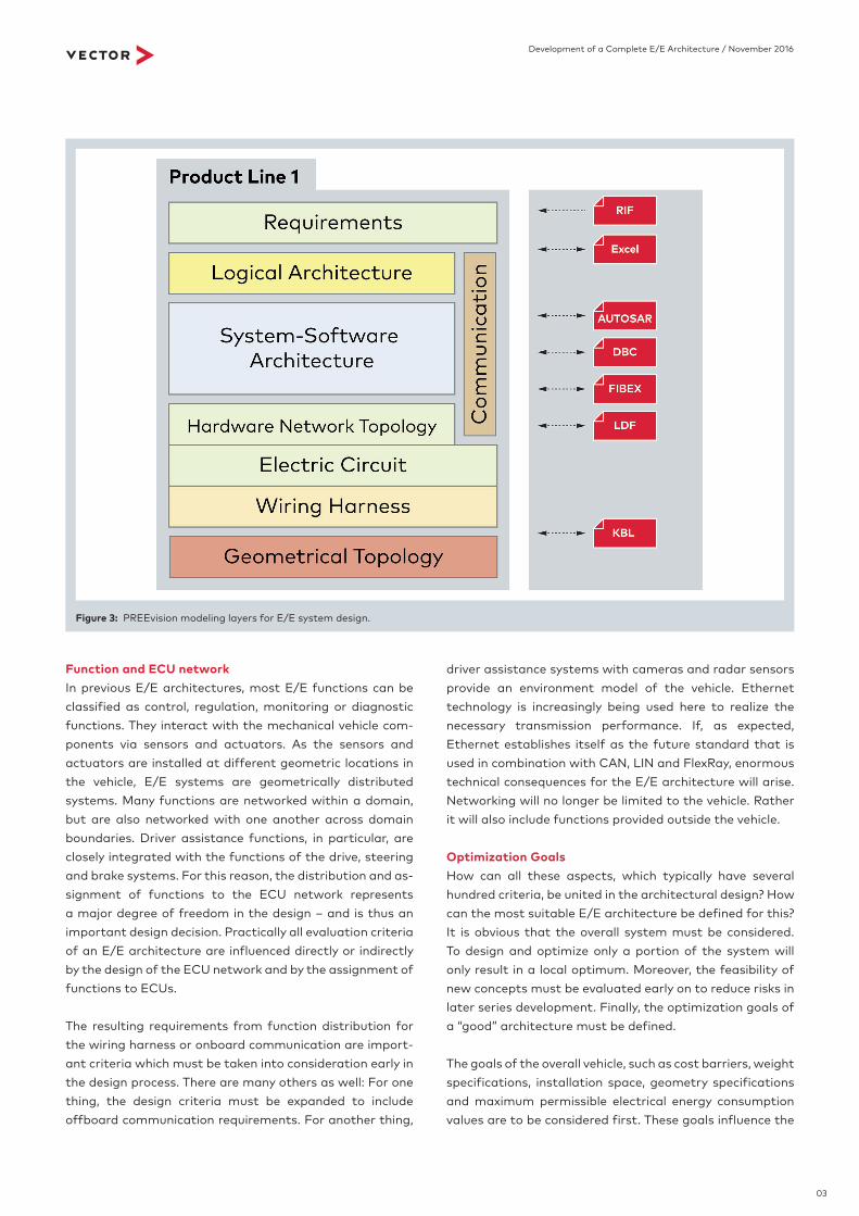
The PREEvision system design tool is structured in the technical layers mentioned (Figure 3). In the data model, everything from the abstraction layers from the geometry layer with installation locations and routing paths to the wiring harness layer, the electric circuit layer and the layer of the ECU network are represented in the vertical direction. The software and communication details are de-signed in parallel with that. Hardware and software as-pects are described abstractly in the layer of the logical function architecture; an even greater degree of abstrac-tion occurs on the layers for requirements and customer functions. The data model is built in the layers mentioned above in such a way that it is understood intuitively in each respective technical area and functions as a domain- specific language. At dedicated points, the layers are avail-able via mappings, which contributes to the decoupled manner of working.
The horizontal direction of the PREEvision model supports decomposition. Hierarchical concepts are available in each layer through decomposition. The third direction in the model is orthogonal to the other two directions and en-ables reuse and variant concepts on each model layer and hierarchy layer. Development progress can also be tracked via integrated version management, and work products can be frozen at specific points in time.
The engineering data model is inspired and shaped by the relevant automotive standards: RIF and ReqIF for require-ments, customer functions and test cases; AUTOSAR for the system, software and communication design; DBC, LDF, FIBEX for specific bus technologies, KBL and VEC for wiring harness and geometry specifications.
Figure 2: Data model and domain-specific representation in PREEvision.
03
Development of a Complete E/E Architecture / November 2016
driver assistance systems with cameras and radar sensors provide an environment model of the vehicle. Ethernet technology is increasingly being used here to realize the necessary transmission performance. If, as expected, Ethernet establishes itself as the future standard that is used in combination with CAN, LIN and FlexRay, enormous technical consequences for the E/E architecture will arise. Networking will no longer be limited to the vehicle. Rather it will also include functions provided outside the vehicle.
Optimization GoalsHow can all these aspects, which typically have several hundred criteria, be united in the architectural design? How can the most suitable E/E architecture be defined for this? It is obvious that the overall system must be considered. To design and optimize only a portion of the system will only result in a local optimum. Moreover, the feasibility of new concepts must be evaluated early on to reduce risks in later series development. Finally, the optimization goals of a “good” architecture must be defined.
The goals of the overall vehicle, such as cost barriers, weight specifications, installation space, geometry specifications and maximum permissible electrical energy consumption values are to be considered first. These goals influence the
Function and ECU networkIn previous E/E architectures, most E/E functions can be classified as control, regulation, monitoring or diagnostic functions. They interact with the mechanical vehicle com-ponents via sensors and actuators. As the sensors and actuators are installed at different geometric locations in the vehicle, E/E systems are geometrically distributed systems. Many functions are networked within a domain, but are also networked with one another across domain boundaries. Driver assistance functions, in particular, are closely integrated with the functions of the drive, steering and brake systems. For this reason, the distribution and as-signment of functions to the ECU network represents a major degree of freedom in the design – and is thus an important design decision. Practically all evaluation criteria of an E/E architecture are influenced directly or indirectly by the design of the ECU network and by the assignment of functions to ECUs.
The resulting requirements from function distribution for the wiring harness or onboard communication are import-ant criteria which must be taken into consideration early in the design process. There are many others as well: For one thing, the design criteria must be expanded to include offboard communication requirements. For another thing,
Figure 3: PREEvision modeling layers for E/E system design.

04
Development of a Complete E/E Architecture / November 2016
Architecture development is not just an activity carried out before the beginning of the series development project, though! In fact, it occurs progressively and at the same time. Architectural decisions and changes are continuously being made during series development and thus affect the architecture of the following generation. This is why close cooperation and exchange between the architecture team and series development is absolutely necessary during the entire development process.
Summary and OutlookTo control the growing functional scope of future E/E sys-tems, an integrated view of the overall architecture within and outside of the vehicle is required. Service-oriented E/E architectures, in particular, are increasingly being used in the driver assistance domain and connectivity environ-ment. First and foremost, they identify the challenges of future architectures!
The consistent use of model-based tools such as PREEvi-sion lends itself to the approach and mastery of these chal-lenges. The many advantages of such comprehensive solu-tions for the overall E/E development process help archi-tects to implement the innovations of the next generation of vehicles and reliably help them reach their goal.
Dipl.-Ing. (FH) Markus Helmling
Product Management Engineer at Vector Informatik GmbH.
Responsible for PREEvision since 2012 with focus on AUTOSAR
communication design.
Translation of a German publication in Hanser Automotive, issue 1-2/2017 Image rights: Vector Informatik GmbH
E/E components from the hardware perspective and also influence the wiring harness. Architecture optimization is not limited to this, however. There is another group of goals that are derived from the implemented vehicle functions. These include real-time requirements for buses and ECUs and all diagnostic and service requirements. Bus load lim-itations and safety requirements are also in this group. E/E architectures are ultimately not just designed for one individual vehicle. Rather, a portfolio of vehicles, vehicle variants and vehicle options must be supported by an E/E architecture. For this reason, the other essential goal cate-gory of product line requirements takes the following into account:
> Variants and options > Expected quantities and proportions of vehicleswith the equipment > Function-oriented decomposition or component- oriented reuse > Building blocks with dedicated use strategies forcomponents and subsystems
Here, the solution is always a compromise between two extremes. On the one hand, there are special E/E compo-nents for a dedicated variant with low production quanti-ties. On the other hand, there are general E/E components for multiple variants with high production quantities but with additional costs for possibly unneeded functionality. The definition of the “best” E/E architecture is thus a non-trivial multidimensional optimization problem.
Architecture Development ProcessModel-based architecture development generally does not start at zero, but rather is a further development of exist-ing architectures. Innovations and optimizations are there-by taken into account for the next architecture generation. Typical steps here are the recording and consolidation of data of the predecessor architecture and its integration and validation. The innovations are then designed for the next-generation architecture. Various alternatives are evaluated and compared with user-defined optimization goals. When a solution is determined, the architecture is exported as the basis for series development. This enables the fast introduction and implementation of new architec-tures in serial developments with high concept quality at the start of development.