prefeasibility report - welcome to environment report of vrkp sponge and power plant llp sy no. 229,...
TRANSCRIPT

Prefeasibility Report
Of
VRKP Sponge and Power Plant LLP
Sy No. 229, 288, 289, Halkundi village, Bellary taluk and district
Karnataka state
Production: TMT Bars (40,000 TPM)
Project Category: A
Prepared By:
M/s Pragathi Labs and Consultants Pvt. Ltd. (Recognized by Ministry of Environment and Forest, Govt. of India)
Plot No. B15 & 16, Industrial Estate
Sanath Nagar, Hyderabad – 500 018

Pre- Feasibility Report VRKP Sponge and Power Plant LLP
M/s Pragathi Labs and Consultants Pvt. Ltd. Page 1
List of Contents
Chapter Title Page No.
1.0
Executive Summary 01-02
1.1 Location Details 01
1.2 Project Proponent 02
2.0
Introduction 03-06
2.1 Identification of the project and project
proponent
03
2.2 Need For the Project and its Importance to the
country or Region
03
2.3 Demand and Supply Gap 04
2.4 Export Possibility 05
2.5 Domestic/Export Markets 06
2.6 Employment Generation (Direct and Indirect)
due to the project
06
3.0
Project Description 07-26
3.1 Type of Project 07
3.2 Location Details 07
3.3 Details of Alternate sites considered 11
3.4 Size or Magnitude of operation 11
3.5 Project Description 11
3.5.1 Rotary Kiln based Sponge Iron Plant 11
3.5.1.1 Manufacturing Process 11
3.5.2 Steel Melting Shop 14
3.5.2.1 Induction Furnace 14
3.5.3 TMT Rolling Mill 17
3.5.3.1 Hot Rolling Process 17
3.5.3.2 Thermo Mechanical Processing 18
3.5.4 Captive Power Plant 19
3.5.4.1 Brief description of major plant and
equipment
20
3.5.4.2 Waste Heat Recovery Boiler 20
3.5.4.3 Flue gas cleaning system 21
3.5.4.4 AFBC Boiler 21
3.5.4.5 Steam Turbine generator 21
3.5.4.6 Deaerator and feed water system 22
3.5.4.7 Electrics 22
3.5.4.8 Instrumentation & Control 22
3.5.4.9 Auxiliary Services 22
3.5.4.10 Ash Handling 22
3.5.4.11 Bottom Ash 22
3.5.4.12 Distributed Control System (DCS) 22
3.6 Raw Material Details 24
3.7 Water Requirement 24

Pre- Feasibility Report VRKP Sponge and Power Plant LLP
M/s Pragathi Labs and Consultants Pvt. Ltd. Page 2
3.8 Power Requirement 25
3.9 Water Pollution Control 25
3.10 Solid Waste Management 25
4.0
Site Analysis 27-31
4.1 Connectivity 27
4.2 Land Details 27
4.3 Existing Social Infrastructure 27
4.4 Geographic Profile and Soil Classification 27
4.5 Secondary Meteorological Data 28
4.5.1 Temperature 29
4.5.2 Relative Humidity 29
4.5.3 Rainfall 30
4.5.4 Wind Speed 30
5.0
Planning 32-33
5.1 Planning Concept 32
5.2 Population Projection 32
5.3 Land Use Planning 33
5.4 Amenities / Facilities 33
6.0
Proposed Infrastructure 34-35
6.1 Industrial and Residential Area 34
6.2 Green Belt Development Plan 34
6.3 Drinking Water management 34
6.4 Industrial Waste Management 35
6.5 Power Requirement 35
7.0 Rehabilitation and Resettlement Plan 36
8.0
Project Schedule and Cost estimates 37
8.1 Time Schedule 37
8.2 Estimated Project Cost 37
9.0 Analysis of Proposal 38
9.1 Financial & social benefits 38
List of Tables
Table No. Title Page No.
1.1 Existing and Expansion details 01
2.1 Indian steel industry sale production 05
3.1 Expansion Details 11
3.2 Raw Material data (Existing + Proposed) 24
3.3 Water requirement details 24
3.4 Power Breakup 25
4.1 Social Land Use of plant surroundings 27
4.2 Secondary Meteorological Data 28
8.1 Proposed Investments 37

Pre- Feasibility Report VRKP Sponge and Power Plant LLP
M/s Pragathi Labs and Consultants Pvt. Ltd. Page 3
List of Figures
Fig. No. Figure Name Page No.
2.1 Growth of Steel Sector in India 04
3.1 Location Map of Plant 08
3.2 Topo map of the project site 09
3.3 Layout Plan of Project site 10
3.4 Schematic Diagram of rotary kiln process 12
3.5 Process Flow diagram of Sponge Iron plant 13
3.6 Process Flow Diagram for Steel Making 17
3.7 Process Flow diagram of TMT rolling mill 19
3.8 Flow Diagram of WHRB based CPP 23
4.1 Monthly variation in Temperature 29
4.2 Monthly comparison of Relative Humidity 30
4.3 Monthly comparison of Rainfall 30
4.4 Monthly average observation of Wind speed 31
4.5 Monthly Comparison of Temperature, Relative
humidity and Rainfall
31

Pre- Feasibility Report VRKP Sponge and Power Plant LLP
M/s Pragathi Labs and Consultants Pvt. Ltd. Page 1
1.0 EXECUTIVE SUMMARY M/s VRKP Sponge and Power Plant LLP proposes to expand the existing Sponge iron plant
at Sy No. 229, 288, 289, Halkundi village, Bellary taluk and district, Karnataka along with
the expansion of Rolling mill, Steel melting shop and captive power generation using the
waste heat and gases. The total capacity of finished products i.e. TMT rods in the expansion
of project is 40,000 MT/month.
The Company has received the Environmental Clearance for the existing Sponge Iron Plant
(1,00,000 TPA), Steel Melting Shop (47,000 TPA), Rolling Mill (72,000 TPA) and Power
Plant (10 MW). The proposed expansion details with total production are detailed in Table
No. 1.1.
Table 1.1 Existing and Expansion details
No Details Existing Production Proposed Production Total Production 1 Sponge Iron Plant 100x3 TPD/1,00,000 TPA 350x3 TPD/3,50,000 TPA 4,50,000 MTPA
2 Steel Melting Shop 12 MT x 1/47,000 MTPA 40 MT x 3/ 4,95,000 MTPA 5,42,000 MTPA
3 Rolling Mill 72,000 MTPA 3,30,000 MTPA 4,02,000 MTPA
4 Power Plant 10 MW 24 MW 34 MW
The source of fresh water required for the expansion project is expected from bore wells. The
waste water of plant will be settled, neutralized in neutralization pit and will be reused in the
plant and there will be zero waste water discharge to outside project boundary. More over
during monsoon season the rain water will be harvested and will be used in the process,
which will help in reducing fresh water intake from bore wells. Power requirement of the
expansion project will be met with the captive power generation and in case of emergency 3
DG sets of 2x1000 and 1x1250 KVA will be utilized.
1.1 Location Details
The proposed project site is located near to Halkundi village, Bellary taluk and district,
Karnataka. No forest land is involved in the project site. The transportation and infrastructure
is already available and is well maintained in the existing area. NH 63 is at a distance of 4.6
km from project site in North direction. Nearest railway station (Bellary) is at a distance of
9.4 km from project site in north-east direction. Nearest airport from the project site (142 km
in SE) is Sri Sathya Sai airport at Puttaparthi which is a domestic airport while Bangalore
airport which is 225 km away from the project site in south direction is a combined domestic
and International Airport. Tungabhadra high level canal is passing from north to south east
and is nearly at a distance of 5.0 km from the project site in North East direction. The
interstate boundary of Andhra Pradesh and Karnataka is at a distance of 0.56 km in south
direction. The total land requirement for the proposed expansion of the project is 388 acres
out of which 88 acres of land already exists and 300 acres of land will be used for further
expansion.

Pre- Feasibility Report VRKP Sponge and Power Plant LLP
M/s Pragathi Labs and Consultants Pvt. Ltd. Page 2
1.2 Project Proponent
Project proponent of M/s VRKP Sponge and Power Plant LLP is Mr. Prateek Agrawal,
having years of experience in steel and Sponge iron manufacturing units. The project
proponent has annual turnover of about Rs. 122.5 Crores. Directors have a vast knowledge in
the field of ferrous and non-ferrous metals, including steel operating medium size
manufacturing units.
VRKP Sponge and Power plant LLP is a Bellary based company and has become a well-
known player in steel industry. The company deals with the manufacture of Sponge Iron,
TMT Bars & Captive Power Plant. The production was so selected because of the vast
knowledge of the directors in the field.
VRKP’s final product of TMT bars is produced through secondary steel melting route using
the best quality iron ore, imported coal and good quality dolomite. It is subsequently
processed through DRI plant and then processed in Induction Furnace (IF) through Ladle
Refining Furnace and then Continuously Cast into Billets. These billets are then send to
rolling mill for further processing with final output as TMT bars of desired sizes. The
resultant steel is of superior quality containing no harmful ingredients and ensures the desired
and consistent properties in TMT bars.
The core competency of the VRKP Sponge and Power Plant LLP is to focus on making
excellent quality of TMT bars and making efficient deliveries to its respective customers. The
rolling mills, DRI plant and the melting shop are continuously upgraded to remain
competitive with the best quality products. At present there is good demand for steel products
like TMT Bars (Thermally Mechanically Treated Bars) which are mainly used in building
constructions, laying of roads, power transmission lines, etc.

Pre- Feasibility Report VRKP Sponge and Power Plant LLP
M/s Pragathi Labs and Consultants Pvt. Ltd. Page 3
2.0 INTRODUCTION
2.1 Identification of the project and project proponent
VRKP Sponge and Power plant LLP is a private limited company, having its registered office
at # 31, TBR Tower, 4th
Floor, New Misssion road, 1st Cross, J.C.Road, Bangalore- 560 027.
The company is promoted by Mr. Prateek Agarwal. Presently, company is involved in
production of TMT bars from rolling mills of 72,000 MT annual capacity at Sy No. 229, 288,
289, Halkundi village, Bellary taluk and district, Karnataka. The industry was formerly under
the control of Hothur Steels and has received EC from SEAC, Karnataka dated 1st January
2009, against application No. HS/FEE/2007, Dated: 25/10/2007 entitled as Establishment of
10 MW captive Power Plant, 72,000 TPA rolling mill and 12 MT Induction Furnaces with
matching LRF & CCM for production of 10,000 TPM TMT bars. Hothur Steels then
transferred the sale deed of the industry to VRKP Sponge and Power Plant LLP on 01st July
2015. Later on, the EC certificate for existing capacity was also transferred to VRKP Sponge
and Power Plant LLP on 23rd
December 2016 with the same conditions and validity period as
given for existing plant.
Now, the company intends to expand its production so as to get 40,000 TPM TMT bars.
Proposed expansion will be carried out partly in the existing plant and partly in the land
adjoining to the existing plant since, the project is running on a land of 88 Acres and on the
vacant space of about 300 acres available beside the existing unit the expansion is proposed.
2.2 Need For the Project and its Importance to the country or Region
Iron and Steel Industry has a very important role to play in India’s economic growth as it is a
developing country. The basic need of Indian economy today is rapid industrialization. The
manufacturing of steel is regarded as one of the key industries in its development. Important
industries like Railway locomotive, Ship Building, Heavy and Light Machinery,
Construction, etc. depend on the availability of iron and steel which is in turn provided by
iron and steel industry and thus becoming the backbone of all industries.
During 2014 through 2015, India was the third largest producer of raw steel and the largest
producer of sponge iron in the world. The industries produced 91.46 million tons of total
finished steel and 9.7 million tons of pig iron. The amount of steel and iron ore a country
produces and consumes is indicative of the building activity, economic and business activity
in the country. Manufacturing and infrastructure are the two key industries that are directly
affected by iron and steel production. The total employee strength of the steel industry in
India is more than two million. This number includes both direct and indirect employees. The
steel manufacturing prowess of a country directly affects it development and economic
growth. Steel and iron ore manufacturing has enabled a developing country like India to
leapfrog from a subsistence agrarian economy to a large industrial economy.
Indian steel is quite cost effective as compared to globally available steel. According to
World Steel Dynamics, the total cost of steel production in the United States is for about
$510 per metric tons, Japan stands at $550, Germany at $557 and Canada at $493. India’s
cost of producing one metric ton of steel stands at $525. This is so because, of the high

Pre- Feasibility Report VRKP Sponge and Power Plant LLP
M/s Pragathi Labs and Consultants Pvt. Ltd. Page 4
material cost coupled with higher import duties. Indian steel industry is expected to be even
more competitive in the coming years with a slashing of duties set on iron ore.
The Indian steel industry is very modern with state-of-the-art steel mills. It has always strived
for continuous modernization and up-gradation of older plants and higher energy efficiency
levels.
Total production of finished steel in India grew by 34% during financial year of April 2016-
February 2017. India is expected to become the world's second largest producer of crude steel
in the next 10 years, moving up from the third position, as its capacity is projected to increase
by 2025. Huge scope for growth is offered by India’s comparatively low per capita steel
consumption and the expected rise in consumption due to increased infrastructure
construction and the thriving automobile and railways sectors.
2.3 Demand and Supply Gap
India has emerged as a net exporter of steel in the year 2016-17, with 97% increase in overall
exports and a 37% decline in imports of steel products over the same period. In the last three
years, there has been capacity addition at a steady Compound annual growth rate (CAGR) of
about 7%. There has also been an improvement in the overall capacity utilization. While the
demand for steel is continuing to grow in traditional sectors, specialized steel is also
increasingly being employed in various hi-tech engineering industries. Globally, a relation
can be observed between steel consumption and the GDP growth rate. The progressive
growth charts of steel products in India for last 5 years are shown in Fig.No.2.1.
Fig No. 2.1 Growth of Steel Sector in India
The most significant policy interventions in India are the rolling out of the National Steel
Policy 2017. The policy will be the road map for the industry in the coming years and will
help in harnessing the sector’s untapped potential. The sale production for steel in india for
last five financial years is given in Table 2.1.

Pre- Feasibility Report VRKP Sponge and Power Plant LLP
M/s Pragathi Labs and Consultants Pvt. Ltd. Page 5
The policy reflects the aspirations of domestic steel industry for achieving 300 MT of
steelmaking capacity by 2030-31. This translates into additional investment of about Rs. 10
lakh crore and 1.1 Million additional workforce getting employed in the steel sector
As part of the NSP, emphasis is also being laid at considering the total life cycle cost while
evaluating projects rather than looking at just the upfront cost in isolation. This would
encourage greater usage of steel in Government as well as private sector. While India roars
on the world stage through its Make in India campaign, it plans to increase steel capacity to
300 million tonnes and per capita steel consumption to a level of 158 Kgs by 2030-31. The
Ministry of Steel is steadfast at making sure that doing business in the steel sector in India is
easier, more profitable, eco-friendly and sustainable while it makes a mark on the global
scene.
Table 2.1 Indian steel industry sale production (million tons)
Category 2011-12 2012-13 2013-14 2014-15 2015-16 April 2016-Jan 2017
Pig Iron 5.37 6.87 7.95 9.69 9.23 7.85
Sponge Iron 19.63 14.33 18.20 20.38 14.53 12.39
Total Finished Steel
(alloy/stainless+non alloy) 75.70 81.68 87.67 92.16 90.98 83.01
Reference- Ministry of Steel, GOI
VRKP Sponge and Power plant LLP has drawn up a growth plan with the objective of
increasing its market share in Indian steel industry which is bound to witness sustained
growth in steel requirement in the years to come. Keeping all these in mind, the Company has
planned to set up the proposed expansion project in a more environment friendly way.
2.4 Export Possibility
Exports of Indian steel have surpassed imports after a gap of three years due to government
measures like the minimum import price (MIP). According to the Joint Plant Committee
figures, during April-February 2017, exports increased 77.48% to 6.62 million tons while
imports fell by 65.20% to 6.59 million tons.
As the Indian steel industry has entered into a new development stage, the steel industries all
over the nation are riding high on the resurgent economy and rising demand for steel. Rapid
rise in production has resulted in India becoming the 3rd
largest producer of crude steel and
the largest producer of sponge iron or DRI in the world. As the demand is more the export
possibility of sponge iron will also be more.
2.5 Domestic/Export Markets
While the demand for steel will continue to grow in traditional sectors such as infrastructure,
construction, steel tubes and pipes, consumer durables, packaging, and ground transportation,
specialized steel will be increasingly used in hi-tech engineering industries such as power
generation, petrochemicals, fertilizers, etc. The new airports and railway metro projects will
require a large amount of steel. Hence the domestic and export markets for steel sector will
rise.

Pre- Feasibility Report VRKP Sponge and Power Plant LLP
M/s Pragathi Labs and Consultants Pvt. Ltd. Page 6
2.6 Employment Generation (Direct and Indirect) due to the project
The project will plan to give more employment opportunities to skilled & unskilled workers
by direct & indirect employment. The project proponent is keen on giving more employment
opportunities to the people living in the surrounding villages around the plant area. The total
man power requirement for proposed expansion is around 831 and the man power for the
existing plant operation is 347. The proposed expansion will comprise of 60% of skilled
employees and 40% of unskilled employees from the total manpower. Besides this some
contractual workers are to be employed to manage canteen, security and housekeeping during
construction as well as operation phase.

Pre- Feasibility Report VRKP Sponge and Power Plant LLP
M/s Pragathi Labs and Consultants Pvt. Ltd. Page 7
3.0 PROJECT DESCRIPTION
3.1 Type of Project
VRKP Sponge and Power Plant LLP located near Halkundi village, Bellary district,
Karnataka is a secondary metallurgical plant manufacturing TMT rods as finished product.
The industry already exists at the same location and now the proponents are planning for the
expansion of its plant. Following are the proposed expansion capacities of the plant.
Enhance the capacity of sponge iron unit by installing 3x350 TPD DRI Kiln from
1,00,000 TPA to 4,50,000 TPA.
Enhance the capacity of steel melting shop by installing 40x3 MT induction furnaces
from 47,000 TPA to 5,42,000 TPA.
Enhance the capacity of rolling mills from 72,000 MTPA to 4,02,000 MTPA
Enhance Power generation from 10 MW to 34 MW through Waste Heat Recovery Boilers
and FBC based boilers.
Proposed expansion will be carried out in the existing plant and the land unused besides
existing plant (300 acres). The land used for expansion will be acquired in the due process.
This project is independent plant without any interlink or interdependence.
3.2 Location Details
The proposed project site is located at Sy No. 229, 288 and 289, Halkundi village, Bellary
taluk and district, Karnataka. The latitude and longitude of the project site are 15o04’0.09” N
and 76o52’9.90”E respectively. Bellary is at a distance of 9.4 km from project site in north-
east direction. The plant area comes under seismic zone II. The location map and
Topographic map of the plant are shown in Fig 3.1 and 3.2 respectively. The layout map of
project site is shown in Fig.3.3.

Pre- Feasibility Report VRKP Sponge and Power Plant LLP
M/s Pragathi Labs and Consultants Pvt. Ltd. Page 8
Fig. 3.1 Location Map of Plant

Pre- Feasibility Report VRKP Sponge and Power Plant LLP
M/s Pragathi Labs and Consultants Pvt. Ltd. Page 9
Fig. 3.2 Topo map of the project site

Pre- Feasibility Report VRKP Sponge and Power Plant LLP
M/s Pragathi Labs and Consultants Pvt. Ltd. Page 10
Fig. 3.3 Layout Plan of Project site

Pre- Feasibility Report VRKP Sponge and Power Plant LLP
M/s Pragathi Labs and Consultants Pvt. Ltd. Page 11
3.3 Details of Alternate sites considered
The proposed expansion project will be executed within the existing plant premises. So no
alternate site has been taken into consideration.
3.4 Size or Magnitude of operation
The proposed expansion project will be setup besides the existing plant site in the area of 300
acres of land which is dry agricultural land and the acquiring of this land is in the process with
additional cost of about 570 crores. The raw materials are acquired with good quality assurance.
The project proposes to use 3016 KLD of water from the bore wells which will be recycled and
reused again with zero discharge method. The project after expansion will produce 40,000 MT/
month TMT rods and bars. The details regarding expansion of the plant is shown in Table 3.1.
Table 3.1 Expansion Details
No Details Existing Production Proposed Production Total Production
1 Sponge Iron Plant 100x3 TPD/1,00,000 TPA 350x3 TPD/3,50,000 TPA 4,50,000 MTPA
2 Steel Melting Shop 12 MT x 1/47,000 MTPA 40 MT x 3/ 4,95,000 MTPA 5,42,000 MTPA
3 Rolling Mill 72,000 MTPA 3,30,000 MTPA 4,02,000 MTPA
4 Power Plant 10 MW 24 MW 34 MW
3.5 Project Description
3.5.1 Rotary Kiln based Sponge Iron Plant
The proposed expansion project is planning to expand three (3) DRI kiln, to 350 TPD capacity
for the total production of 4,50,000 TPA sponge iron.
The major plant facilities for the Sponge Iron plant envisaged are as follows
Day bins
Rotary Kiln & Cooler
Central Control Room
Product processing and product storage
Off gas system including waste heat recovery power generation
3.5.1.1 Manufacturing Process
The plant proposes to use the coal based process in which iron oxide in Pellet form will be
reduced with coal in a rotary kiln to make sponge iron. The raw materials (Pellet, coal and
dolomite), in desired quantities and sizes, are fed into the rotary kiln from the feed end, after the
rotary kiln has been fired and reaches the desired temperature.
The process starts with rotary kiln as the main reactor where the reduction of iron ore in the form
of iron oxide is carried out with coal acting as reductant. The inner of steel frame shell kiln will
be protected by refractory lining. The kiln will have a slope of 2.50 down towards the discharge

Pre- Feasibility Report VRKP Sponge and Power Plant LLP
M/s Pragathi Labs and Consultants Pvt. Ltd. Page 12
end. Air blowers having dampers will be provided on the kiln shell in different heating zones for
introducing air for combustion. Sized iron ore and coal shall be fed in to the kiln at the feeding
end with the help of weigh feeders. Due to the slope and rotational movement of the kiln the
charge will move towards the discharge end. Temperature measurement and control shall be
done with the help of thermocouples provided in different heating zones of the kiln. Additional
coal requirement shall be met by injecting fine coal through the discharge end of the kiln.
Kiln discharge consisting of mixture of sponge iron and dolochar, mixture of unreduced iron, un-
calcinated limestone/Dolomite, gangue and semi burnt coal, will be passed on to a rotary cooler
where water will be sprayed to cool the discharge mix to about 120°C. The cooler discharge will
fall on to a hopper and taken through conveyers for screening of fines and coarse materials and
subsequently subjected to magnetic separation where sponge iron will be separated from
dolochar. The reducing gases generated from the combustion of the coal will flow in the counter
current direction and emerge from the feed end of the kiln which will be maintained at a positive
pressure of about +5 mm water column. The flue gases will then pass through a gravitational
Dust Settling Chamber (DSC) and then to the After Burner Chamber (ABC) where CO will get
converted to non-toxic CO2. The flue gas at about 900°C to 1000°C, will be taken to the Waste
Heat Recovery Boilers (WHRB) to utilize the waste heat content of flue gases.
The rotary kiln diagram is shown in Fig. 3.3 and the Schematic Process flow diagram of sponge
iron unit is depicted in Fig. 3.4.
Fig 3.4 Schematic Diagram of rotary kiln process

Pre- Feasibility Report VRKP Sponge and Power Plant LLP
M/s Pragathi Labs and Consultants Pvt. Ltd. Page 13
Fig. 3.5 Process Flow diagram of Sponge Iron plant

Pre- Feasibility Report VRKP Sponge and Power Plant LLP
M/s Pragathi Labs and Consultants Pvt. Ltd. Page 14
3.5.2 Steel Melting Shop
Steel is made in steel melting shop in the refractory lined vessels called LD Converters by
blowing oxygen through the hot metal bath. While iron making is a reduction process, steel
making is an oxidation process. The oxygen reacts with impurities like carbon, silicon,
phosphorous, sulphur etc. present in hot metal to produce steel. No external fuel is required as
the silicon & carbon releases huge amount of heat energy. Also the carbon reaction releases large
quantities of gas rich in carbon monoxide along with huge amount of dust. The gases released
from the converter are collected, cooled, cleaned and recovered for use as fuel in the steel plant.
The entire molten steel is continuously cast at the radial type continuous casting machines
resulting in significant energy conservation and better quality steel. The proposed expanded
capacity of steel melting shop is 5,42,000 TPA through 3 x 40 MT and 12 x 1 MT induction
furnace.
3.5.2.1 Induction Furnace
An induction furnace is an electrical furnace in which the heat is applied by induction
heating of metal. An induction furnace consists of a nonconductive crucible holding the charge
of metal to be melted, surrounded by a coil of copper wire. A powerful alternating current flows
through the wire. The coil creates a rapidly reversing magnetic field that penetrates the metal.
The magnetic field induces eddy currents, circular electric currents, inside the metal,
by electromagnetic induction. The eddy currents, flowing through the electrical resistance of the
bulk metal, heat it by Joule heating. Once melted, the eddy currents cause vigorous stirring of the
melt, assuring good mixing. An advantage of induction heating is that the heat is generated
within the furnace's charge itself rather than applied by a burning fuel or other external heat
source, which can be important in applications where contamination is an issue.
Generally, the smaller the volume of the melts, the higher the frequency of the furnace used, this
is due to the skin depth which is a measure of the distance an alternating current can penetrate
beneath the surface of a conductor. For the same conductivity, the higher frequencies have a
shallow skin depth i.e. less penetration into the melt. Lower frequencies can generate stirring or
turbulence in the metal.
The process for manufacturing of steel is described in following stages.
Melting the charge mixed of steel and Iron scrap
The furnace is switched on, current starts flowing at a high rate and a comparatively low voltage
through the induction coils of the furnace, producing an induced magnetic field inside the central
space of the coils where the crucible is located. The induced magnetic fluxes thus generated out
through the packed charge in the crucible, which is placed centrally inside the induction coil.
As the magnetic fluxes generated out through the scraps and complete the circuit, they generate
and induce eddy current in the scrap. This induced eddy current, as it flows through the highly
resistive bath of scrap, generates tremendous heat and melting starts. It is thus apparent that the

Pre- Feasibility Report VRKP Sponge and Power Plant LLP
M/s Pragathi Labs and Consultants Pvt. Ltd. Page 15
melting rate depends primarily on two things (1) the density of magnetic fluxes and (2)
compactness of the charge. The charge mixed arrangement has already been described. The
magnetic fluxes can be controlled by varying input of power to the furnace, especially the current
and frequency.
In a medium frequency furnace, the frequency range normally varies between 150-10K
cycles/second. This heat is developed mainly in the outer rim of the metal in the charge but is
carried quickly to the center by conduction. Spontaneously, a pool of molten metal is formed in
the bottom causing the charge to sink. At this point any remaining charge mixed is added
gradually. The eddy current, which is generated in the charge, has other uses. It imparts a molten
effect on the liquid steel, which is thereby stirred and mixed and heated more homogeneously.
This stirring effect is inversely proportional to the frequency of the furnace and so that furnace
frequency is selected in accordance with the purpose for which the furnace will be utilized.
The melting continues till all the charge is melted and the bath develops a convex surface.
However as the convex surface is not favorable to slag treatment, the power input is then
naturally decreased to flatten the convexity and to reduce the circulation rate when refining under
a reducing slag. The reduced flow of the liquid metal accelerates the purification reactions by
constantly bringing new metal into close contact with the slag. Before the actual reduction of
steel is done, the liquid steel which might contain some trapped oxygen is first treated with some
suitable deoxidizer. When no purification is attempted, the chief metallurgical advantages of the
process attributable to the stirring action are uniformity of the product, control over the super
heat temperature and the opportunity afforded by the conditions of the melt to control de-
oxidation through proper addition.
As soon as the charge has melted and de-oxidizing ions have ceased, any objectionable slag is
skimmed off, and the necessary alloying elements are added. When these additives have melted
and diffused through the bath of the power input may be increased to bring the temperature of
metal up to the point most desirable for pouring. The current is then turned off and the furnace is
tilted for pouring into a ladle. As soon as pouring has ceased, any slag adhering to the wall of the
crucible is crapped out and the furnace is readied for charging again.
As the furnace is equipped with a higher cover over the crucible very little oxidation occurs
during melting. Such a cover also serves to prevent cooling by radiation from the surface heat
loss and protecting the metal is unnecessary, though slags are used in special cases. Another
advantage of the induction furnace is that there is hardly any melting loss compared with the arc
furnace.
Ladle Teaming Practice
The molten metal from crucible taken out in a ladle by tilting the crucible and crucible is made
free for further charge of next batch.

Pre- Feasibility Report VRKP Sponge and Power Plant LLP
M/s Pragathi Labs and Consultants Pvt. Ltd. Page 16
Direct Teeming Practice
In addition to the bottom pouring Ladle Teeming process, Direct Teeming process can also be
used as and when required. Direct teeming of liquid metal from induction furnace to mould
assemble is another process of the Billet casting practice. In this process the mould assemble
comprising bottom plate; Billet mould and trumpet properly lined with refractories are placed on
top of a rail bound transfer trolley moving across in front of the crucible which is supported
properly from the furnace structure.
While teeming the mould bogie transfer car is so positioned that the trumpet of the mould
assembly is properly aligned with the outlet nozzle of the tundish. The liquid metal from the
spout is directed through the tundish to the trumpet for casting of Billets. After the teeming is
over, the car is moved aside for stripping and removal of Billets. Normally two (2) such transfer
cars are provided. While one is engaged for casting purposes the other is kept ready for next
melt. Direct teeming practice obviates the use of stopper sleeve, stopper head and ladle refractory
and requires only a nominal quantity of refractory for lining the tundish and thus affects
substantial savings in refractory costs.
Continuous Casting Machine
The molten steel from the IF or the ladle metallurgical facility is cast in a continuous casting
machine (6/11 2 stand Billet Caster) to produce cast shapes including billets. In some processes,
the cast shape is torch cut to length and transported hot to the hot rolling mill for further
processing. Other steel mills have reheat furnaces. Steel billets are allowed to cool, and then be
reheated in a furnace prior to rolling the billets into bars or other shapes.
Castings operations consist of following
Preparation
Match Plates (Patterns)
Preparation of moulds
Pouring of molten steel into prepared moulds
Solidification of molten steel
Knocking of moulds
Removal of runners & risers.
Finishing of casting/ Ingots.
1) The process is continuous because liquid steel is continuously poured into a bottomless
mould at the same rate as a continuous steel casting is extracted.
2) Before casting begins a dummy bar is used to close the bottom of the mould.
3) A ladle of molten steel is lifted above the casting machine and a hole in the bottom of the
ladle is opened, allowing the liquid steel to pour into the mould to form the required
shape.

Pre- Feasibility Report VRKP Sponge and Power Plant LLP
M/s Pragathi Labs and Consultants Pvt. Ltd. Page 17
4) As the steel’s outer surface solidifies in the mould, the dummy bar is slowly withdrawn
through the machine, pulling the steel with it.
5) Water is sprayed along the machine to cool/solidify the steel.
6) At the end of the machine, the steel is cut to the required length by gas torches.
The process flow diagram of Steel Melting Shop is shown below in Fig. 3.5.
Fig. 3.6 Process Flow Diagram for Steel Making
3.5.3 TMT Rolling Mill
In rolling mill the working principle is based on metal forming process in which the metal stock
is passed through one or more pairs of rolls to reduce the thickness and to make the thickness
uniform. Rolling is classified according to the temperature of the metal rolled. If the temperature
of the metal is above its recrystallization temperature, then the process is known as hot
rolling. Roll stands and holding pairs of rolls are grouped together into rolling mills that can
quickly process metal, typically steel, into products such as structural steel (I-beams, angle stock,
channel stock, and so on), bar stock, and rails. Rolling mill divisions can convert the semi-
finished casting products into finished products. The company has planned to expand the rolling
mill for production of 40,000 MT/ month TMT bars as a finished product.
3.5.3.1 Hot Rolling Process
Hot rolling is a metalworking process that occurs above the recrystallization temperature of the
material. After the grains deform during processing, they recrystallize, which maintains

Pre- Feasibility Report VRKP Sponge and Power Plant LLP
M/s Pragathi Labs and Consultants Pvt. Ltd. Page 18
an equated microstructure and prevents the metal from work hardening. The starting material is
usually large pieces of metal, like semi-finished casting products, such as slabs, blooms, and
billets. If these products came from a continuous casting operation the products are usually fed
directly into the rolling mills at the proper temperature. In smaller operations the material starts
at room temperature and must be heated. This is done in a gas- or oil-fired soaking pit for larger
work pieces and for smaller work pieces induction heating is used. As the material is worked the
temperature must be monitored to make sure it remains above the recrystallization temperature.
To maintain a safety factor a finishing temperature is defined above the recrystallization
temperature which is usually 50 to 100 °C (90 to 180 °F) above the recrystallization temperature.
If the temperature does drop below this temperature the material must be re-heated before more
hot rolling.
3.5.3.2 Thermo Mechanical Processing
Thermo-mechanical processing, is a metallurgical process that combines mechanical or plastic
deformation process like compression or forging, rolling etc. with thermal processes like heat-
treatment, water quenching, heating and cooling at various rates into a single process.
The quenching process produces a high strength bar from inexpensive low carbon steel. The
process quenches the surface layer of the bar, which pressurizes and deforms the crystal structure
of intermediate layers, and simultaneously begins to temper the quenched layers using the heat
from the bar's core. Steel billets are heated to approximately 1200°C to 1250°C in a reheat
furnace. Then, they are progressively rolled to reduce the billets to the final size and shape
of reinforcing bar. After the last rolling stand, the billet moves through a quench box. The
quenching converts the billet's surface layer to martensite, and causes it to shrink. The shrinkage
pressurizes the core, helping to form the correct crystal structures. The core remains hot,
and austenitic. A microprocessor controls the water flow to the quench box, to manage the
temperature difference through the cross-section of the bars. The correct temperature difference
assures that all processes occur, and bars have the necessary mechanical properties.
The bar leaves the quench box with a temperature gradient through its cross section. As the bar
cools, heat flows from the bar's center to its surface so that the bar's heat and pressure correctly
tempers an intermediate ring of martensite and bainite. Finally, the slow cooling after quenching
automatically tempers the austenitic core to ferrite and pearlite on the cooling bed.
These bars therefore exhibit a variation in microstructure in their cross section, having strong,
tough, tempered martensite in the surface layer of the bar, an intermediate layer of martensite
and bainite, and a refined, tough and ductile ferrite and pearlite core.
When the cut ends of TMT bars are etched in Nital (a mixture of nitric acid and methanol), three
distinct rings appear:
1) A tempered outer ring of martensite
2) A semi-tempered middle ring of martensite and bainite, and
3) A mild circular core of bainite, ferrite and pearlite.
This is the desired micro structure for quality construction rebar.

Pre- Feasibility Report VRKP Sponge and Power Plant LLP
M/s Pragathi Labs and Consultants Pvt. Ltd. Page 19
In contrast, lower grades of rebar are twisted when cold, work hardening them to increase their
strength. However, after thermo mechanical treatment (TMT), bars do not need more work
hardening. As there is no twisting during TMT, no torsional stress occurs, and so torsional stress
cannot form surface defects in TMT bars. Therefore TMT bars resist corrosion better than cold,
twisted and deformed (CTD) bars.
After thermo-mechanical processing, some grades in which TMT Bars can be covered includes
Fe: 415 /500 /550/ 600. These are much stronger compared with conventional CTD Bars and
give up to 20% more strength to concrete structure with same quantity of steel.
The process flow diagram of rolling mill is shown in Fig. 3.6.
Fig. 3.7 Process Flow diagram of TMT rolling mill
3.5.4 Captive Power Plant
A captive power plant also called auto-producer or embedded generation is a power generation
facility used and managed by an industrial or commercial energy user for its own energy
consumption. Captive power plants can operate off-grid or they can be connected to the electric
grid to exchange excess generation. Captive power plants are generally used by power-intensive

Pre- Feasibility Report VRKP Sponge and Power Plant LLP
M/s Pragathi Labs and Consultants Pvt. Ltd. Page 20
industries where continuity and quality of energy supply are crucial, such as aluminum
smelters, steel plants, chemical industries etc.
The Proponents of the industry intends to expand the capacity of Captive Power Plant upto 34
MW, out of which 17 MW will be based on WHR Boiler, utilizing waste heat from the DRI plant
and 17 MW, based on AFBC Boiler, utilizing dolochar from the DRI plant & imported coal.
3.5.4.1 Brief description of major plant and equipment
Waste Heat Recovery Boilers will be installed behind the ABC of existing DRI kilns in bypass
configuration. The flue gases after ABC will be taken to uni-fired furnace chamber and then flow
over banks of super heater, convective evaporator and economizer before being discharged to
atmosphere through ESP, ID fan and stack. In the proposed Fluidized Bed Combustion (FBC)
boiler, combustion of fuel particles is achieved in suspension with an inert aggregate i.e. sand.
Combustion air will be fed through air nozzles from underneath into the sand fuel bed. Oil
burner will be provided for startup and low load flame stabilization. The fuel proposed for FBC
Boiler is dolochar. The flue gases will pass over various heat transfer surfaces to ESP and then
finally discharged into chimney by ID fan. Condensate extraction pumps will pump the
condensate after condenser of STG to a common de-aerator. Feed water from the de-aerator will
be pumped to the waste heat recovery boiler as well as FBC boiler by boiler feed pumps. The
steam generated from both the Waste Heat Recovery boilers and AFBC boilers will drive the
steam turbine through a common steam header.
The proposed plant will comprise the following major systems:
Fluidized bed combustion boiler with auxiliaries
Steam turbine generator and auxiliaries
De-aerator and feed water system
Electrical systems
Instrumentation and controls
Compressed air system (service air and instrument air)
Handling & hoisting facilities
Plant communication system
Ventilation and air conditioning
Fire-fighting detection & alarm system
3.5.4.2 Waste Heat Recovery Boiler
After burning chamber (ABC) and Dust settling chamber (DSC) will be located at the exit of
DRI Plant Kilns. Part of the dust carried by the waste gases will settle down at DSC. The DSC
and ABC assembly will be connected to the DRI Plant Kilns through refractory lined duct.
The combustibles in the waste gases are burnt in the After Burning Chamber which will raise the
waste gas temperature thus making the waste gases free from carbon mono-oxide. Provision for
spraying water will be made to control the temperature if required. From ABC outlet the WHRB
will be connected through a refractory lined duct. An emergency stack cap on top of ABC will be
Pre- Feasibility Report VRKP Sponge and Power Plant LLP
M/s Pragathi Labs and Consultants Pvt. Ltd. Page 21
provided for diverting the waste gases to atmosphere when WHRB is under shutdown or break
down.
The boiler will be complete with evaporator steam drum, mud drum, bank of super heaters,
economizer, attemperator, air fans, ESP, internal piping etc. Soot blowing and super heater
attemperation system will also be provided. Boiler will be provided with blow down tanks (IBD,
CBD etc), sample cooler.
3.5.4.3 Flue gas cleaning system
The exhaust gases will be discharged from boiler to ESP and then into the atmosphere through
induced Draft fan and chimney. The pressure drop in the boiler ducts and ESP will be kept to
match with the requirement of existing ID fan. The boiler will be of semi-outdoor type with a
weather canopy and side covering of trapeze corrugated steel sheets or other suitable materials,
as available.
The gases passing out of WHRB will be passed through one multi-field Electrostatic Precipitator
before releasing the gas, having huge quantity of dust particles, into the atmosphere. The ESP
will be installed between the WHRB and the stack. The dust content in the gas, downstream of
ESP shall be limited to 50 mg/Nm3. The ESP Unit will be provided with transformers, rectifier
and controls. The dust particles will be collected below ESP in hoppers and conveyed by means
of conveyors or pneumatically and stored in silos. This will be subsequently disposed off by
trucks.
3.5.4.4 AFBC Boiler
It has been proposed to install a 4 MW capacity captive power plant based on AFBC Boiler,
utilizing dolochar from the DRI Plants (existing & proposed) & imported coal. The AFBC boiler
plant shall comprise of boiler and its auxiliaries.
3.5.4.5 Steam Turbine generator
There shall be one TG of 34 MW capacity. The Steam turbine will be single, Horizontal, Single
blade condensing type. The set shall be complete with gear box, barring gear box, condenser, air
evacuation system condensate extract pumps, generator cooling systems, gland sealing with
gland vent condenser and lube oil system. Condensing steam turbine generator with inlet steam
parameter of 66 ata and 465±5°C at emergency steam valve inlet is provided.
Conversion of Heat Energy in Steam to Mechanical work will be done by expanding the same in
Steam Turbine which shall provide mechanical energy in the form of rotational torque. Steam
while passing through various stages of Turbine will release both pressure and temperature and
will be ultimately dumped to Condenser at near vacuum condition.
Low pressure steam will be condensed by air in Air Cooled Condenser. Condensed Water from
the Air Cooled Condenser will be fed back to boiler through Air Ejector, Gland Steam
Condenser and De-aerator for re-generative heating and air removal. Boiler Feed Pump shall take
suction from De-aerator and feed de-aerated water to boiler economizer.

Pre- Feasibility Report VRKP Sponge and Power Plant LLP
M/s Pragathi Labs and Consultants Pvt. Ltd. Page 22
3.5.4.6 Deaerator and feed water system
There will be a de-aerator with feed tank. 2 boiler feed water pumps with motors (1 working + 1
stand by) shall be provided along with common suction header, auto recirculation valve,
suction/discharge valve, non-return valve, pressure gauge, temperature gauge etc.
3.5.4.7 Electrics
The electrics include generators, transformers, switchgear – main and auxiliary, battery room etc.
3.5.4.8 Instrumentation & Control
Effective control and measurement of process parameters along with data acquisition system in
the control room has been envisaged.
3.5.4.9 Auxiliary Services
Auxiliary service systems such as ash handling, EOT crane, telecommunication, air conditioning
and ventilation shall be adequately envisaged.
3.5.4.10 Ash Handling
Ash handling plant system design would be based on bottom and fly ash quantities. The fly ash
from the proposed AFBC boiler will be collected in economizer hoppers, air heater hoppers, ESP
hoppers and will be conveyed through dense phase pneumatic conveying system to silo. The fly
ash to be disposed from the silo will be moistened to reduce the dust while collecting the ash.
The system will be provided with telescopic chute and rotary feeder for loading the ash into
covered trucks.
3.5.4.11 Bottom Ash
Bottom ash from proposed AFBC boiler will be carried through a submerged belt conveyor to
silo. From silo it will be disposed to ash dump area in covered trucks in moistened condition.
3.5.4.12 Distributed Control System (DCS)
The control system for Captive thermal power plant shall be DCS based with complete
interlocking, protection, control and monitoring of the main power plant (i.e. Boiler & Turbine)
other than BOP packages like Ash handling, Coal handling, DM plant, Air compressors etc.
However for Turbine governing, there can be a dedicated control system by the Turbine supplier
in case the control is not envisaged through the main DCS.
DCS has the advantage over PLC/SCADA with respect to advanced control features in open
loops and closed loops, execution timers, flexible operational features, standard display groups
etc. Especially in closed loop control, DCS has an edge over the conventional PLCs in capability

Pre- Feasibility Report VRKP Sponge and Power Plant LLP
M/s Pragathi Labs and Consultants Pvt. Ltd. Page 23
and response times. And hence it is recommended to have a suitable version of present day DCS
system of reputed make.
Indicative process flow diagram of WHRB captive power plant is shown in Fig. 3.7.
Fig. 3.8 Flow Diagram of WHRB based CPP

Pre- Feasibility Report VRKP Sponge and Power Plant LLP
M/s Pragathi Labs and Consultants Pvt. Ltd. Page 24
3.6 Raw Material Details
The raw materials which are proposed in the expansion project consist of Sponge Iron, dolomite,
imported coal etc. The annual requirement of major raw materials, which will be required for the
proposed project, is presented in Table 3.2
Table 3.2 Raw Material data (Existing + Proposed)
Name
Existing Details Proposed Details Total
(MT/month) Quantity
(MT/month) Storage
Quantity
(MT/month) Storage
Pallet/Iron Ore 15000/20000 Open 45000/60000 Open 60000/80000
South African coal 10000 Shed 30000 Shed 40000
Indonesian Coal 2000 Shed 6000 Shed 8000
Dolomite/Limestone 300/1658 Shed 900/4800 Shed 1200/6458
Sponge finished goods 9000 Storage Bins 27000 Storage Bins 34000
Raw material for SMS 10000 Shed 45000 Shed 55000
Billets 10000 Shed 30000 Shed 40000
In addition to the above indicated major raw materials LDO/HSD & lubricating oil will also be
required for meeting the requirement of various production modules of the plant.
The raw materials as well as finished products will be following the transport link of road
network passing through Bellary and joining NH-63 for further transportation to desired
locations. The raw materials & products will be covered fully during the transportation to avoid
spillage & dust emissions on the road.
3.7 Water Requirement
Ground water through bore wells will be used for meeting the daily water requirement of the
plant. There is a provision for overhead water tank reservoir for water storage.
The proponents already acquire the permission to use 1558 KLD of water for existing plant
operations. As per an initial estimate around 3016 KLD will be needed for the proposed
expansion project. Thus the total water requirement will be 4574 KLD. The estimated unit wise
make up water requirement for the proposed project are given below.
Table 3.3 Water requirement details
Particulars Water Requirement (KLD)
Existing Proposed Total
Sponge Iron Plant 100 400 500
Power Plant 1050 500 1550
Steel Melting Shop 200 1600 1800
Rolling Mill 200 500 700
Domestic 8 16 24
Total 1558 3016 4574

Pre- Feasibility Report VRKP Sponge and Power Plant LLP
M/s Pragathi Labs and Consultants Pvt. Ltd. Page 25
3.8 Power Requirement
The estimated power requirement of the proposed unit is around 89.5 MW. The power
requirement will be met from total 34 MW captive power plant and from nearby grid of state.
Unit wise power breakup for the proposed project is given in Table 3.4.
Table 3.4 Power Breakup
Particulars Power Requirement (MW)
Existing Proposed Total
Sponge Iron Plant 1.5 5 6.5
Power Plant 1 3.5 4.5
Steel Melting Shop 10 55 65
Rolling Mill 2.5 7 9.5
Domestic 1 3 4
Total 16 73.5 89.5
3.9 Water Pollution Control
Waste water generated from the different areas of the plant will be treated to the desired extent in
suitable treatment facilities and recycled back to the process, as far as practicable, facilitating
adequate reuse of-water in the respective recirculating systems and economizing on the make-up
water requirement.
There is no wastewater generation from the existing plant as Closed circuit cooling system is
being adopted. Boiler blowdown & DM plant regeneration wastewater is being treated in
Neutralization tanks and is being mixed in a Central Monitoring Basin (CMB). The treated
effluent from CMB is being utilized for dust suppression, ash conditioning and for greenbelt
development. Only wastewater is sanitary wastewater, which is being treated in septic tank
followed by sub-surface dispersion trench. Zero liquid effluent discharge is being maintained in
the existing plant.
The Boiler blowdown will be controlled to maintain system solids loading within normal limits
for proper water chemistry. The effluent will have less than 100 ppm suspended solids and will
be led into the station sump mix with other station effluents to reduce temperature and utilized
for disposal of ash in slurry form.
Surface run-off will be settled in a settling basin prior to reuse/ disposal.
3.10 Solid Waste Management
Solid wastes that will be generated from IF are slag and dust. The hot slag generated from IF will
be transferred to slag yard after cooling. IF slag will be used for road construction and land
filling purpose. Dolo-char from the DRI units will be used in AFBC boiler. Solid wastes that
will be generated from caster are the scales. The scales are collected from the drain and
transferred to IF for reuse.

Pre- Feasibility Report VRKP Sponge and Power Plant LLP
M/s Pragathi Labs and Consultants Pvt. Ltd. Page 26
The solid wastes from the rolling mill are end cuts and miss rolls, which will be re-used in
induction furnace. The fly ash generated from Captive Power Plant will be sold as a raw material
for cement plants and brick manufacturing. The bottom ash from CPP will be used as land
filling. Fly ash and bottom ash from ESP and Boiler furnace will be transferred by close pipes to
two closed silos. From silos that ash will be transferred in closed trucks and then brought to
cement and brick manufacturing. The landfill will be lined by plastic liner and ash, conveyors
will be periodically sprayed with water to avoid fugitive dust. As per guidelines of government
procedure of waste disposal to the landfill, maximum utilization of solid waste will be made to
level the different layers of land in and around the plant.

Pre- Feasibility Report VRKP Sponge and Power Plant LLP
M/s Pragathi Labs and Consultants Pvt. Ltd. Page 27
4.0 SITE ANALYSIS
The proposed expansion project requires 300 acres of land apart from 88 acres of existing land.
The expansion will be subjected at the dry land besides the existing unit. The surroundings of the
plant area is very well developed with good infrastructure and transport network.
4.1 Connectivity
The project site is very well connected with rail, road and air transport. NH 63 is at a distance of
4.6 km from project site in north direction. Nearest railway station (Bellary) is at a distance of
9.4 km from project site in north-east direction. Nearest airport from the project site (142 km in
SE) is Sri Sathya Sai airport at Puttaparthi which is a domestic airport while Bangalore airport
which is 225 km away from the project site in south direction is a combined domestic and
International Airport.
4.2 Land Details
Existing plant is located at Halkundi village, Bellary district, Karnataka. Proposed expansion will
be carried out inside the existing plant premises utilizing the un-used area. Total land envisaged
for the entire project will be 300 acres. Total land after proposed expansion will be 388 acres and
same is in possession of management. The project area spans between Latitude 15°04'0.09"N
and 76°52'9.90"E Longitude. The entire project area will fall in the Survey of India Topo sheet
no. 57G/7 and 57G/8.
4.3 Existing Social Infrastructure
Table 4.1 Social Land Use of plant surroundings
Particulars Details Dist. (km) Dir.
Nearest village Halkundi 1.8 NE
Nearest Town Bellary 9.4 NE
Nearest Forest Mincheri RF 2.5 SE
Nearest River/Canal Tungabhadra high level canal 4.9 NE
Nearest Hospital Panduranga Hospital, Bellary 10.1 NE
Nearest Educational Facility Nandi International School, Bellary 7.6 NW
Nearest Religious Place Jamia masjid, Mincheri 4.5 E
Interstate Boundary Andhra Pradesh and Karnataka 0.6 S
Dist. and dir. w.r.t. Plant
4.4 Geographic Profile and Soil Classification
Bellary district is spread over in the central region of the eastern sector of the state. Total area of
the district is 9885 Sq.kms. The district is endowed with three major economic resources:
agricultural land, a mighty river and an abundance of mineral deposits. Tungabharda which

Pre- Feasibility Report VRKP Sponge and Power Plant LLP
M/s Pragathi Labs and Consultants Pvt. Ltd. Page 28
flows all along the western and the northern boundary of the district is the most important river.
It has two tributaries, namely the Hagari in the east and Chikka-Hagari in the west. In addition,
there are a few minor streams which ultimately flow into the river Tungabhadra.
Bellary district is situated in and arid zone. The rainfall is scanty and capricious. It consists of
Achaean complex composed of crystalline schist, epidorites, granitic, gneisses and later granites.
The Sandur hill range cuts across the district from north - west to south and divides the district
into two distinct natural divisions. The eastern portion is smaller and consists of a free less plain
country with sporadic rocky hills. On the other hand, the western portion which is larger abounds
in picturesque valleys studded with lush green vegetation and enhancing sceneries. Of these, the
Sandur valley deserves a special mention. The hill above the famous Kumaraswamy temple near
Sandur rises to a height of 1020 meters above the mean sea level and incidentally this peak
happens to be the highest point in the district.
While the soils in the western decision are predominantly sandy & red loamy, those in the
eastern portion covering the taluks of Bellary and Siruguppa are mainly of the deep black -
cotton type. Under rain fed conditions, these soils yield the crops of Jowar, Cotton & Groundnut.
However when suitably irrigated the same lands would yield paddy and sugarcane as well.
4.5 Secondary Meteorological Data
The latest and updated secondary data for 30 years (1981 – 2010) is procured from IMD, Pune
for observing parameters like Temperature, Relative humidity, Rainfall, Wind speed and Wind
direction in the Bellary district of Karnataka. The data is summarized in Table 4.2. The
ombrothermic diagram for the IMD data is shown in Fig. 4.5.
Table 4.2 Secondary Meteorological Data (Avg. years 1981-2010)
Month Temp. (°C) RH (%) RF
(mm)
WS
(Kmph) WD
Max. Min. Max. Min.
January 31.4 15.6 70 43 2.9 3.9 SE
February 34.4 18.1 61 37 2.3 3.6 E
March 38.1 21.1 51 30 6 3.8 E
April 40.4 23.9 50 29 17.2 4.6 NW
May 39.6 24.4 55 34 54.3 7 NW
June 35.3 23.3 66 50 59.2 10 W
July 32.7 23 68 56 42.6 10.7 W
August 31.9 22.7 70 58 70 9.9 W
September 32.3 21.9 72 58 111 6.8 W
October 31.8 20.9 73 62 89 3.7 W
November 30.8 18.3 72 56 39.5 2.8 E
December 30.2 15.6 71 50 5.5 4.2 E
Average 34.1 20.73 65 47 41.63 5.9
Ref: Data collected from IMD, Pune for Bellary district

Pre- Feasibility Report VRKP Sponge and Power Plant LLP
M/s Pragathi Labs and Consultants Pvt. Ltd. Page 29
4.5.1 Temperature
Temperature is a measure of a quality of a state of a material. Temperature may be regarded as
the most extensively studied universal ecological factor which greatly affects the vital activities
such as metabolism, behavior, reproduction and development. Temperature fluctuations have
been more pronounced in the air than in the water medium. Temperature is known to influence
or gets largely influenced by other environmental factors such as moisture and wind.
Temperature influences the dispersion of gases in the ambient air and it is now used in the
prediction of air quality models.
The maximum temperature is 40.4oC recorded in summer season in the month of April. The
minimum temperature is 15.6oC recorded in winter season in the month of December. The
average annual temperature was 27.4oC. The monthly mean of maximum and minimum
temperatures are depicted in Fig.4.1.
Fig. 4.1 Monthly variation in Temperature
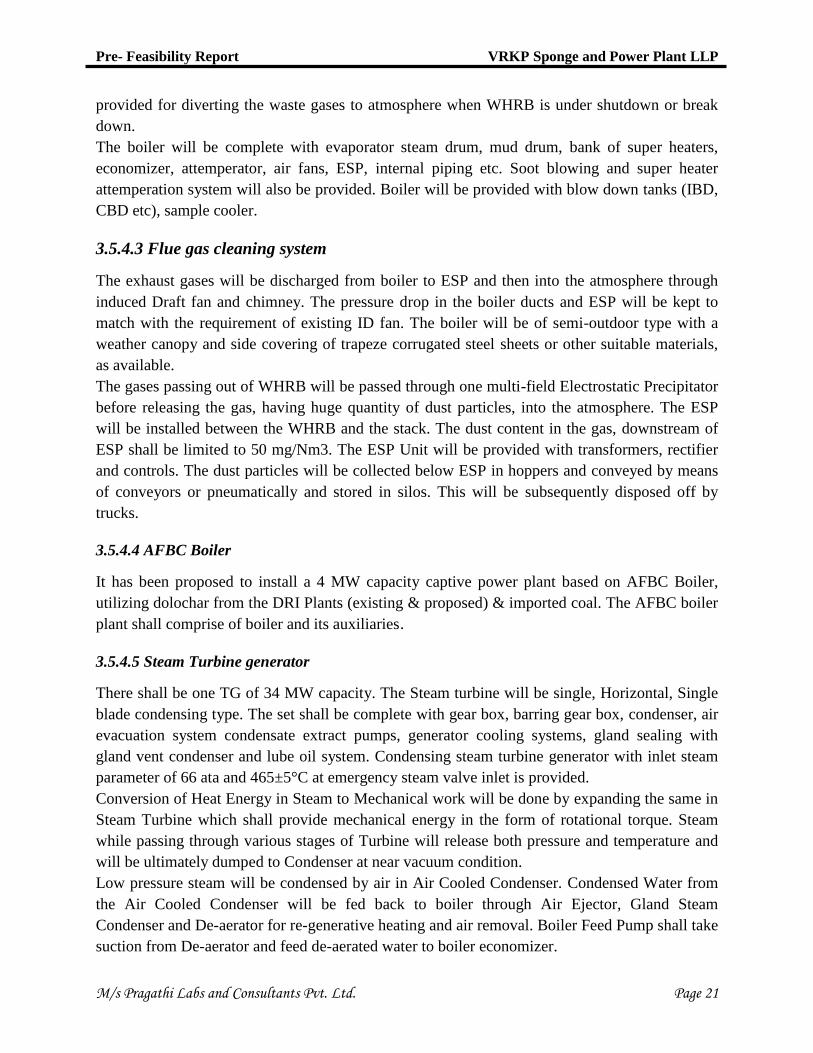
4.5.2 Relative Humidity
Relative humidity is the ratio of the partial pressure of water vapor to the equilibrium vapor
pressure of water at a given temperature. Relative humidity depends on temperature and the
pressure of the system. Relative humidity is usually high during rainy days when moist air passes
over the area. Higher values are normally observed during the nights and early mornings while it
is opposite during day and early evenings.
The average relative humidity at 8:30 hrs and 17:30 hrs were 65 and 47 % respectively. The
maximum relative humidity was observed in months of September, October and November,
while the minimum relative humidity was observed in months of March, April and May. The
month wise mean maximum and minimum relative humidity is depicted in Fig. 4.2.
Pre- Feasibility Report VRKP Sponge and Power Plant LLP
M/s Pragathi Labs and Consultants Pvt. Ltd. Page 30
Fig. 4.2 Monthly comparison of Relative Humidity
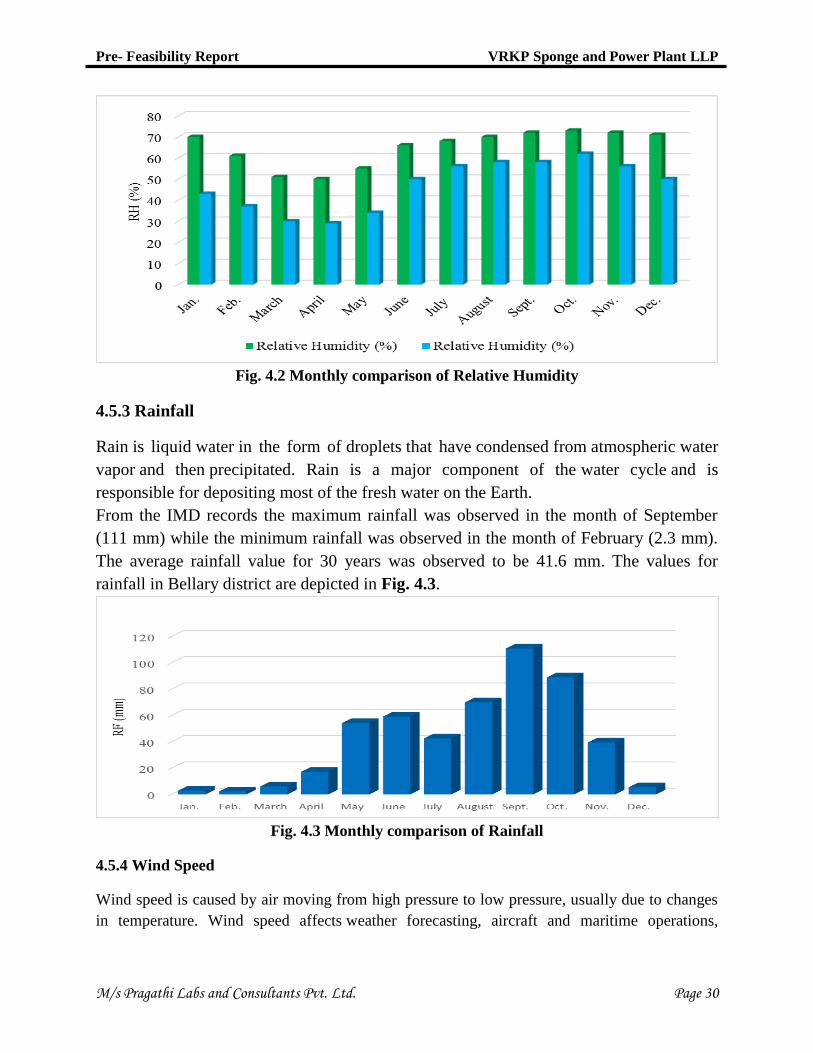
4.5.3 Rainfall
Rain is liquid water in the form of droplets that have condensed from atmospheric water
vapor and then precipitated. Rain is a major component of the water cycle and is
responsible for depositing most of the fresh water on the Earth.
From the IMD records the maximum rainfall was observed in the month of September
(111 mm) while the minimum rainfall was observed in the month of February (2.3 mm).
The average rainfall value for 30 years was observed to be 41.6 mm. The values for
rainfall in Bellary district are depicted in Fig. 4.3.
Fig. 4.3 Monthly comparison of Rainfall
4.5.4 Wind Speed
Wind speed is caused by air moving from high pressure to low pressure, usually due to changes
in temperature. Wind speed affects weather forecasting, aircraft and maritime operations,

Pre- Feasibility Report VRKP Sponge and Power Plant LLP
M/s Pragathi Labs and Consultants Pvt. Ltd. Page 31
construction projects, growth and metabolism rate of many plant species, and countless other
implications. Wind speed is measured with an anemometer.
The data obtained from IMD for Bellary district shows the maximum wind speed was recorded
during July (10.7 Kmph). Predominant wind direction was observed to be west. The wind speed
variation is depicted in Fig. 4.4.
Fig.No.4.4 Monthly average observation of Wind speed
Ref: Data collected from IMD, Pune for Bellary District
Fig.No.4.5 Monthly Comparison of Temperature, Relative humidity and Rainfall

Pre- Feasibility Report VRKP Sponge and Power Plant LLP
M/s Pragathi Labs and Consultants Pvt. Ltd. Page 32
5.0 PLANNING
5.1 Planning Concept
The installation of several production units along with utilities and services require co-operation
for procurement of equipment, equipment foundations, award of all contracts and supervision of
all construction jobs at plant site. The factors which are responsible for timely implementation of
the project are
Arrangement of proper finance for the project.
Finalization of layout of the proposed plant.
Design of utilities and services.
Placement of orders for plant and machinery.
Arrangements for Govt. sanctions and supply of power.
Recruitment of personnel.
The plant is an integrated steel plant having captive power generation. It is a labor intensive
project. However, depending on the production schedule, there will be additional technical labor
engaged for production operations.
The raw materials shall be transported through covered trucks by road up to the plant premises.
And the finished products will be transported by road. The transportation load will not add much
to the existing load on the said road system.
Appropriate plantation program shall be undertaken along with the developmental program to at
least cover the boundary areas with thick and tall plants for containment of the air borne
pollutants within the premises. The seasonal water body passing through the existing plant will
come inside the plant after expansion. So it will be diverted through the boundary of the
proposed plant with entry and exit points of the nalla being the same.
There will not be any further infrastructural development other than needed for the
commissioning of the total project component machineries. This expansion-commodification
shall utilize the existing infrastructural facilities for all purposes.
5.2 Population Projection
As per 2011 census the population of the district stood at 24,52,595 (Male : 12,36,954, Female :
12,15,641). Rural Population is 15,32,356 and Urban population is 9,20,239. Scheduled Castes
population is 5,17,409 and Scheduled Tribes population is 4,51,406.The geographical area is
8447 sq. km. It has 2 revenue sub divisions, Bellary subdivision and Hospet subdivision, which
in all have seven taluks. The Bellary subdivision has 3 taluks, while there are four taluks in
Hospet subdivision. There are 27 hoblies, two CMC's, one town municipality, seven town
panchayats, 542 revenue villages, and 436 thandas/habitations. The rural population constitutes
62% of the total population. The density of population is 290 per sq. km. The scheduled
caste/scheduled tribe population constitutes 39.50% of the total population. The sex-ratio was
983. The normal rainfall is 639 mm. The major occupation of this district is agriculture and 75%

Pre- Feasibility Report VRKP Sponge and Power Plant LLP
M/s Pragathi Labs and Consultants Pvt. Ltd. Page 33
total labor force is dependent on agriculture for its livelihood. The most common language in the
district is Kannada.
There are no major human settlements in the close vicinity of the project site. The manpower
requirement will be sourced from the local areas to the extent possible hence not much of
settlement of outside people in the area is expected. However population concentration may
increase in the surrounding habitations of the plant due to increase in ancillary activities.
5.3 Land Use Planning
Existing plant is located at Sy No. 229, 288, 289, Halkundi village, Bellary taluk and district,
Karnataka. Existing plant is located in 88 acres of land. Proposed expansion will accumulate in
300 acres of land. Total land after proposed expansion will be 388 acres and same is in
possession of management.
5.4 Amenities / Facilities
Facilities like canteen, rest room and washrooms has already been provided in the existing plant
as basic facilities to workers. No other additional facilities are proposed.

Pre- Feasibility Report VRKP Sponge and Power Plant LLP
M/s Pragathi Labs and Consultants Pvt. Ltd. Page 34
6.0 PROPOSED INFRASTRUCTURE
6.1 Industrial and Residential Area
Proposed project will be planned besides existing plant premises. The area is a dry agriculture
land which will be developed as an industrial area. The expansion project will be accommodated
besides the boundary of existing premises of project site. The main plant area comprises of DRI
Kilns, Induction furnace, Furnace sheds, Rolling mill area, captive power plant area, raw
material storage and product storage etc.
No colonization is proposed in the expansion of this project. Facilities like canteen, rest room,
washrooms, quality control block and administration block are already available in the plant
premises and will be developed as per the demand.
6.2 Green Belt Development Plan
The green belt is a set of rows of trees planted in such a way that they form an effective barrier
between the plant and the surrounding areas. Prevalent wind directions shall be taken into
consideration to ensure adequate capturing of the air pollutants around the plant. Open spaces,
where tree plantation is not possible shall be covered with shrubs and grass. The plantations shall
match with the general landscape of the area and be aesthetically pleasant. Adequate attention
will be paid to planting of trees and their maintenance and protection.
In order to combat the air pollution, noise pollution and also to improve the aesthetic, the
company proposes to develop greenbelt, landscaping and avenue plantation. 33% of the total
area i.e. about 128 acres of land will be demarcated for green belt purpose as per the expansion
of the project. For that purpose certain plans are adopted which are enlisted below:
Local DFO will be consulted in developing the green belt.
Greenbelt of 33% of the area will be developed in the plant premises as per CPCB
guidelines.
15 m wide greenbelt will be maintained all around the plant.
The tree species to be selected for the plantation are pollutant tolerant, fast growing, wind
firm and deep rooted.
A three tier plantation is proposed comprising of an outer most belt of taller trees which
will act as barrier, middle core acting as air cleaner and the innermost core which may be
termed as absorptive layer consisting of trees which are known to be particularly tolerant
to pollutants.
6.3 Drinking Water management
It is estimated that 16 KLD of water will be required for domestic purpose during operation of
proposed expansion of the plant. The desired amount of water will be drawn from ground water
through bore wells.

Pre- Feasibility Report VRKP Sponge and Power Plant LLP
M/s Pragathi Labs and Consultants Pvt. Ltd. Page 35
6.4 Industrial Waste Management
The wastes which will be generated from the industrial process are used oil, ash and slag. The
induction furnace slag being equivalent to river sand can be used as land filling. The ash will be
used for land filling as well as it will be supplied to brick manufacturing units. The air pollutants
from raw material handling, transfer points and storage units will be mitigated by implying
suitable measures like water sprinkling, tarpaulin covers on conveyor belts, trucks and sheds.
The air pollutants from Power plant, DRI Kilns and induction furnace will be mitigated by the
use of ESP and bag filters. The hazardous waste like used and waste oil will be disposed as per
Hazardous waste disposal management. The waste water from domestic sources will be sent to
septic tank followed by soak pit. Effluents from power plant will be treated and after ensuring
the quality of water from KSPCB norms, it will be utilized for operations, dust suppression, ash
conditioning and for greenbelt development. Zero liquid effluent discharge is being maintained
in the existing plant.
6.5 Power Requirement
Power requirement after expansion will be about 89.5 MW and captive generation will be
34 MW, hence about 55.5 MW will be incorporated from the district power supply.

Pre- Feasibility Report VRKP Sponge and Power Plant LLP
M/s Pragathi Labs and Consultants Pvt. Ltd. Page 36
7.0 REHABILITATION AND RESETTLEMENT PLAN
The proposed expansion units will be implemented in the existing plant premises. The existing
land is already derived as industrial land. As settlement will not be affected so, no R&R facility
is anticipated.

Pre- Feasibility Report VRKP Sponge and Power Plant LLP
M/s Pragathi Labs and Consultants Pvt. Ltd. Page 37
8.0 PROJECT SCHEDULE AND COST ESTIMATES
8.1 Time Schedule
The plant will be implemented in 2 years from the date of receipt of Environmental Clearance
from the MoEF&CC, New Delhi & Consent from KSPCB. Some works will proceed parallel and
some in series. Critical Path Method (CPM) and Project Evaluation & Review Technique
(PERT) will be followed for completion of project work. In short the schedule of expansion of
plant will be completed within two years of time after getting EC.
8.2 Estimated Project Cost
The total estimated cost of expansion of the plant is 570 crores. The details of unit wise breakup
of cost are given in Table 8.1.
Table 8.1 Proposed Investments
Details Investment (Crores)
Sponge Iron Plant 100
Power Plant 120
Steel Melting Shop 150
Rolling Mill 150
Land 30
Miscellaneous 20
Total 570

Pre- Feasibility Report VRKP Sponge and Power Plant LLP
M/s Pragathi Labs and Consultants Pvt. Ltd. Page 38
9.0 ANALYSIS OF PROPOSAL
9.1 Financial & social benefits
The proposed expansion project is expected to bring socio-economic and environmental benefits
both at local and global level as described below
Social awareness programs will be further improved by the local authority such as sanitation
and hygiene, HIV Prevention Program.
Through this project, adult education and female education will be provided to the illiterate
adults and backward females of the villages in the project surrounding area.
The proposed expansion project will set up training center for the male and female youth
group by considering their skills and qualification which will support the people for self-
employment.
The project is going to create substantial employment and income.
Due to this project activity, some persons in the project area will be recruited as skilled and
semi-skilled workers by the company as per its policy. Therefore, substantial amount of
employment and income is likely to be generated for the local people. So, the project will
contribute in a positive manner towards direct employment in the project area.
Generating additional associated jobs due to establishment of the project.
VRKP Sponge and Power Plant LLP shall produce TMT rods and bars that will be utilized in
construction activities. The products are in demand and production shall contribute to the
GDP growth of the country.
Primary health center will be developed by the project proponents and the medical facilities
will certainly improve due to the proposed expansion project.
The outcome shows that results are positive which indicate a positive feasibility