preliminary design and computational analysis of an ...lyrintzi/aiaa-2011-918-deepak.pdf · ccl cfx...
TRANSCRIPT
Preliminary Design and Computational Analysis of an
Ejector Nozzle with Chevrons
Deepak Thirumurthy∗
Energy Division, Rolls-Royce North America, Mount Vernon, OH 43050
Gregory A. Blaisdell†, Anastasios S. Lyrintzis‡ and John P. Sullivan§
School of Aeronautics and Astronautics, Purdue University, West Lafayette, IN 47907
The jet propulsion exhaust nozzle system is an integral part of an airbreathing gasturbine engine and critical to its overall performance. Challenges associated with thedesign and manufacturing of an exhaust nozzle increases with the cruise speed of theaircraft. The exhaust nozzle system for a supersonic cruise aircraft mandates additionalfeatures such as variable throat and exit area, jet noise suppression, and reverse thrust. Inthe past, in order to address this challenge, an ejector nozzle with clamshells was designedand fabricated. The experimental investigation and computation of the nozzle at lowsubsonic conditions showed the presence of a recirculation zone at the inner surface ofthe clamshells. The present work summarizes the computational simulation of the ejectornozzle with clamshells at flight conditions. Similar recirculation zones were predicted at theinner surface of the clamshells. Initiatives were taken to improve the ejector performanceby the elimination of the recirculation zone. The current nozzle design was modified bythe application of chevrons on the nozzle throat. A preliminary design and computationalanalysis of the ejector nozzle with clamshells and chevrons was carried out. Two designcases with different number of chevrons were implemented and their computational analysiswas successfully carried out. It was observed that the nozzle flow features were improvedbecause of enhanced mixing and the recirculation zone was decreased in its extent.
Nomenclature
CAD Computer-aided-designCCL CFX command languageCD Convergent-divergentCFD Computational fluid dynamicsCFL Courant-Friedrichs-LewyCNC Computed-numerically-controlledDES Detached eddy simulationsGRC Glenn Research CenterHSR High speed researchIGES Initial graphics exchange specificationLES Large eddy simulationsNASA National Aeronautics and Space AdministrationNPR Nozzle pressure ratioPIV Particle image velocimetryRANS Reynolds-averaged Navier-StokesSCAR Supersonic cruise aircraft researchSST Supersonic transport
∗Mechanical Engineer, Turbomachinery R&D, [email protected], Member AIAA.†Associate Professor, School of Aeronautics & Astronautics, [email protected], Associate Fellow AIAA.‡Professor, School of Aeronautics & Astronautics, [email protected], Associate Fellow AIAA.§Professor, School of Aeronautics & Astronautics, [email protected], Associate Fellow AIAA.
1 of 17
American Institute of Aeronautics and Astronautics
49th AIAA Aerospace Sciences Meeting including the New Horizons Forum and Aerospace Exposition4 - 7 January 2011, Orlando, Florida
AIAA 2011-918
Copyright © 2011 by Deepak Thirumurthy. Published by the American Institute of Aeronautics and Astronautics, Inc., with permission.
SST Shear stress transportSTEP Standard for the exchange of productTKE Turbulent kinetic energyUDF User defined functionsAt Nozzle throat cross-section area (m2)DEQ Equivalent diameter of the nozzle throat (m)Mthroat Nozzle throat Mach numberReD Reynolds number based on the nozzle throat equivalent diameterU Centerline jet axial velocity (m/s)Uplenum Mean axial velocity inside the rig plenum (m/s)U∗ Frictional velocity at the wall (m/s)k Turbulent kinetic energy (m2/s2)mej Secondary mass flow entrained through the ejector slot (kg/s)min Primary nozzle mass flow (kg/s)y+ Normalized wall distance
Greek Alphabetsε Turbulent kinetic energy dissipation rate (m2/s3)ν Kinematic viscosity of the fluid (m2/s)ω Specific turbulent kinetic energy dissipation rate (s−1)
I. Introduction
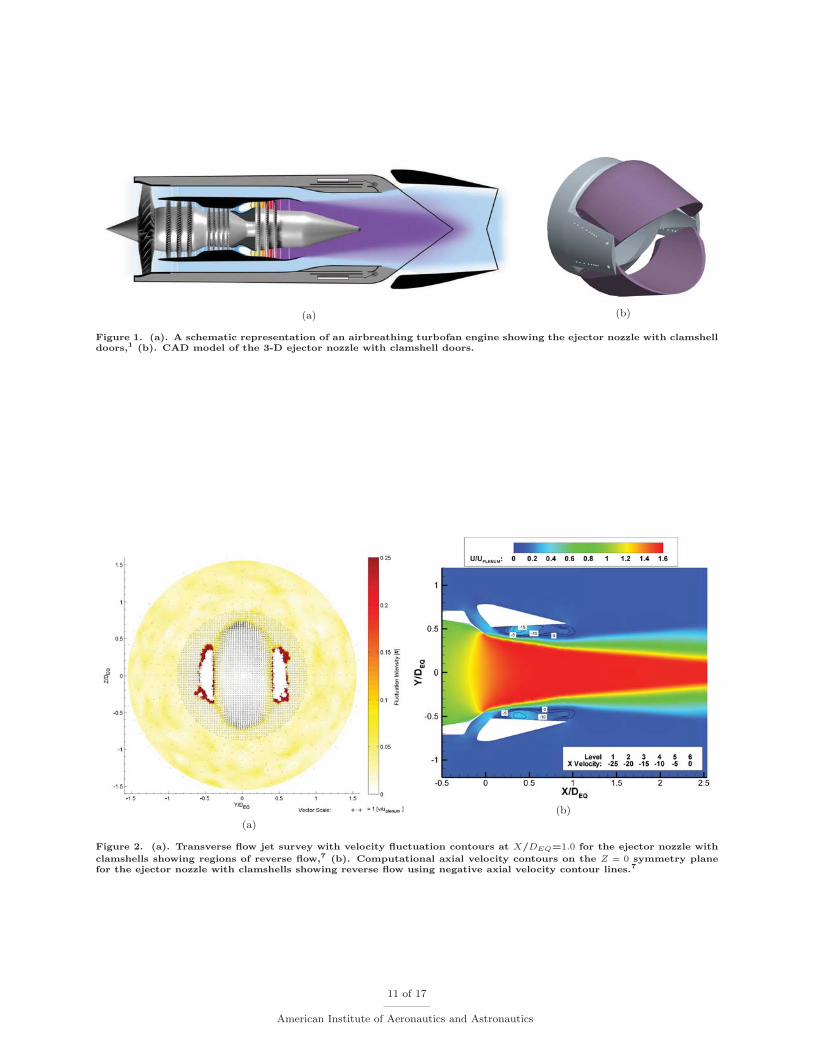
Design requirements for a viable supersonic transport aircraft pose conflicting requirements on thedesign and configuration of the propulsion system.1 The performance of the exhaust nozzle is critical to theoverall system performance as it provides the required thrust efficiently during different phases of flight suchas subsonic take-off, transonic acceleration, supersonic cruise and subsonic approach. Engine manufacturerRolls-Royce and business class aircraft manufacturer Gulfstream Aerospace Corporation are collaboratingon the development of technologies for a supersonic jet. Figure 1(a) shows the schematic representation of ahigh-speed turbofan engine with variable area nozzle. Research and technology development activities werecarried out at the Rolls-Royce university technology center for high Mach propulsion, Purdue university.Two different supersonic exhaust nozzle concepts viz. the shrouded plug nozzle and the ejector nozzle withclamshells, were extensively studied and their experimental investigation and computation was carried out.2–4
The present work summarizes the results obtained from the computational simulation of the ejector nozzleat flight conditions. In the past, a similar ejector nozzle was used in the Olympus-593 engine which poweredthe Concorde aircraft.
The potential of ejectors in thrust augmentation and jet noise reduction was identified during the 1960s,during various supersonic transport programs. From 1960 to 1985, several supersonic transport programssuch as the supersonic transport (SST:1963-1972), supersonic cruise aircraft research (SCAR:1975-1981)and high speed research (HSR) were started and several new ejector-based nozzle concepts were realized.A comprehensive summary of various nozzles designed during these supersonic transport programs andtheir experimental results is given by Stitt.5 Ejector propulsion nozzles have several advantages such asjet noise reduction, infra-red signature control, and improvement in the converging-diverging (CD) nozzlegross thrust coefficient in certain operating regimes.6 A recent study demonstrated the application of ejectorphenomenon in extracting the nacelle boundary layer and resulting in a nacelle drag reduction.6 Additionally,the potential of the entrained ejector flow in effective thermal management by acting as a cool heat sink fornacelle-immersed heat exchangers was explored.
II. Experimental Investigation and Computation7
In the past, a new design of the ejector nozzle with clamshells was proposed and fabricated using thecomputed-numerically-controlled (CNC) technique. Figure 1(b) shows the computer-aided-design (CAD)model of the ejector nozzle with clamshell doors. The experimental investigation of the ejector nozzle withclamshells at low subsonic conditions was carried out in the Boeing wind tunnel at Purdue University’s
2 of 17
American Institute of Aeronautics and Astronautics
Aerospace Sciences Laboratory. The test nozzle was of 0.123 scale operated at approximately Mthroat = 0.25and ReD = 760, 000. The experimental results showed a zone of flow separation at the inner surface of theclamshells, as shown in Figure 2(a).
Computational simulations of the ejector nozzle with and without clamshells were carried out to under-stand the flow physics in a better way. A zone of flow separation, similar to experiments, was captured atthe inner surface of the clamshells and shown in Figure 2(b). It was concluded that this flow separation wasbecause of the inability of the resulting free shear layer in attaching with the inner surface of the clamshells.This study was extended by the computational simulation of the nozzle at flight conditions. Similar re-circulation zones were encountered at the inner surface of the clamshells. In the present work chevronsare introduced on the nozzle throat to enhance mixing and minimize the recirculation zone. The design,computational analysis, and results are discussed.
III. Design Philosophy
The presence of a zone of separation and recirculation near the inner surface of the clamshells haddetrimental effects on the advantages of the ejector nozzle with clamshell doors, such as reduced thrustaugmentation and noise suppression. The flow was separated because of the inability of the free shearlayers, originating from the primary nozzle surface, to attach to the inner surface of the clamshells. Thisphenomenon was studied in detail by Der.8
One of the proposed measures to overcome flow separation and recirculation zones is to introduce stream-wise vortices in the ejector flow by the application of passive mixing devices such as chevrons or tabs, therebyenhancing the mixing between the ejector flow and the nozzle flow. The concept of chevrons is not new andhas already been used in civil air-transportation powerplants such as the Rolls-Royce Trent-1000 and theGeneral Electric GE-NX. The application of chevrons on the ejector nozzle is expected to result in theenhanced spreading of the jet and forces the shear layer to attach to the inner surface of the clamshellsthereby reducing the flow separation as shown in Figure 3. In addition to the ejector nozzle performanceimprovement, chevrons have noise suppression capability in the low frequency part of the spectrum.
The term Chevrons literally means a V-shaped pattern and in the context of jet engines, a chevronnozzle features triangular serrated trailing edge. When compared with a baseline axisymmetric nozzle, thisadditional feature promotes streamwise vortices, which along with the naturally occurring toroidal vortices,accelerate the mixing between the jet exhaust and surrounding atmospheric air. Enhanced mixing resultsin a reduction of the exhaust velocity and therefore the jet noise in accordance with the Lighthill’s eighthpower law (U8).9
The ejector nozzle with chevrons introduces counter-rotating streamwise vortices into the primary nozzleflow. These kidney-shaped vortices interact with the ejector flow and the primary nozzle flow. This resultsin an increased mixing and outward spreading of the shear layer which finally attaches to the inner surface ofthe clamshell doors. The design of the chevron is critical from the aeroacoustic point of view. The enhancedmixing results in additional small-scale eddies which produce high frequency noise. Hence the design of thechevron should be such that it increases the mixing with minimum high frequency noise penalty. This canbe achieved by the use of advanced optimization techniques.
As compared to other passive mixers such as corrugated mixers, which suffer from additional weight, drag,and increased specific fuel consumption, chevrons offer simplicity in design, manufacturing, and maintenancewith much smaller weight and high frequency penalties.10 As an example of previous studies, Kenzakowskiet al.11 studied the effect of passive noise reduction devices such as chevrons and tabs in plume mixingenhancement and compared the mean and turbulent flow fields obtained using the in-house CRAFT flowsolver with experiments conducted at National Aeronautics and Space Administration (NASA) Glenn Re-search Center (GRC). Also, Bridges and Brown12 conducted a parametric experimental study of the chevronnozzles. They performed flow field measurements using particle image velocimetry (PIV) and acoustic-fieldmeasurements on single-flow hot and cold jets with chevrons, varying their count, penetration length, andsymmetry.
IV. Nozzle Design and CAD Geometry
The baseline ejector nozzle geometry used in the current design task was scaled up (8.13 : 1) to representthe full-scale flight geometry. The baseline CAD geometry, parametrically defined using the CATIA CAD
3 of 17
American Institute of Aeronautics and Astronautics
package, was exported as a standard for the exchange of product (STEP) model file for better compatibilitywith the Pro/Engineer CAD package. Chevrons were designed based on the dimensions from the previousstudy of Janardan et al. and documented in reference.13 Various dimensional variables used in the design ofthe chevron are given in Table 1.
The chevron on the nozzle surface was created using the Pro/Engineer Wildfire 4.0 CAD package. Solidmodeling operations such as extrusion and subtraction were used to cut the nozzle throat surface in the formof chevrons. In the current study, two designs were implemented which differ from each other in the totalnumber of chevrons and their dimensions. Design I consisted of 12 chevrons resulting in the chevron-creston the ejector nozzle Z=0 symmetry plane. Design II was based on the dimensions corresponding to 14chevrons and resulted in the chevron-trough on the ejector nozzle Z=0 symmetry plane. The chevron-crestis defined as the peak of the chevron and the chevron-trough is defined as the middle point in between thetwo chevron peaks. The basic features of the above mentioned two designs are tabulated in Table 1.
Table 1. Dimensions of the chevron on the 3-D ejector nozzle with clamshell doors for Design I and Design II.
Variable Design I Design IINozzle circumference (C = πD) 17.93 in. 17.93 in.Total number of chevrons (N) 12 14
Actual number of chevrons (Na) 8 10Chevron arc length (s=C/N) 1.494 in. 1.281 in.
Length of the chevron (l) 1.00 in. 0.92 in.Chevron angle at the throat center (θ=360◦/N) 30.0◦ 25.7◦
Included angle at chevron tip (Φ) 90◦ 90◦
The presence of the clamshell door-support allowed only 8 and 10 chevrons for Design I and DesignII, respectively. The isometric views of the ejector nozzle with 8 chevrons and 10 chevrons are shown inFigures 4(a) and 4(b), respectively.
V. Computational Analysis
Detailed computational simulations of the above mentioned two designs were carried out using commer-cial computational fluid dynamics (CFD) flow solvers viz. the ANSYS FLUENT and the ANSYS CFX. Inaddition to this, Rolls-Royce in-house HYDRA-CFD flow solver was used for comparison. The computa-tional simulation of the baseline nozzle (without chevrons) was performed for the flow field comparison andnozzle performance analysis. Details about the computational mesh, boundary conditions implemented, anddiscussion on the flow solvers are as follows:
A. Computational Mesh
As a first step towards the three-dimensional computational simulation of the ejector nozzle with chevrons,computational meshes for the baseline ejector nozzle (without chevrons), ejector nozzle with 12 chevrons(Design I) and ejector nozzle with 14 chevrons (Design II) were created. Grids were created using thePointwise GRIDGEN14 version 15.10 grid generation code. The nozzle geometry was exported in the initialgraphics exchange specification (IGES) format from the Pro/Engineer Wildfire v4.0 CAD package withedges and surfaces as the required entities. Edges are required for the creation of connectors and surfacesare required for creating databases on which GRIDGEN projects the surface mesh.
A 3-D, multiblock, nonoverlapping hybrid grid was created. An unstructured mesh was used on chevronsurfaces which were extruded as prisms for the boundary layer mesh. Structured blocks were used for thefar field and shear layer region. The nozzle geometry was symmetric about the Y =0 and Z=0 plane. Hencea quadrant of the geometry was used for grid generation and CFD simulation.
In order to capture the streamwise vortices introduced by the chevrons, additional grid points were placedinside the unstructured block in the form of a structured block. The interface between the structured andunstructured blocks consisted of pyramid cells. The present CFD simulation involved high subsonic Machnumbers inside the nozzle (flight conditions) and hence a refined wall resolution was required to capture thethin boundary layers near the walls. A variable wall-normal spacing was used to keep the y+ values within
4 of 17
American Institute of Aeronautics and Astronautics
the range of 30 ∼ 300 and hence wall functions were used for the near wall turbulence. y+ is defined as
y+ =(
yU∗ν
), (1)
where U∗ is the frictional velocity at the nearest wall and ν is the kinematic viscosity of the fluid.The mesh for the baseline ejector nozzle with clamshells consisted of 28 blocks resulting in a total of 2.0
million cells. The computational domain for Design I consisted of a total of 29 blocks resulting in a total of3.36 million cells. The total number of blocks included one unstructured block enclosing the region of theclamshell doors and chevrons. Figure 5(a) shows the computational mesh for the Design I nozzle. Similarly,the computational mesh for Design II consisted of 31 blocks resulting in a total of 3.56 million cells. Thismesh is shown in Figure 5(b).
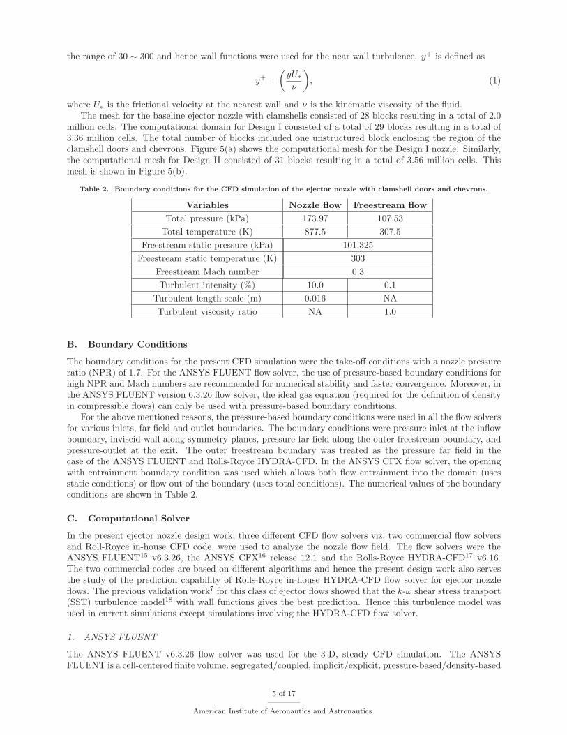
Table 2. Boundary conditions for the CFD simulation of the ejector nozzle with clamshell doors and chevrons.
Variables Nozzle flow Freestream flowTotal pressure (kPa) 173.97 107.53
Total temperature (K) 877.5 307.5Freestream static pressure (kPa) 101.325
Freestream static temperature (K) 303Freestream Mach number 0.3Turbulent intensity (%) 10.0 0.1
Turbulent length scale (m) 0.016 NATurbulent viscosity ratio NA 1.0
B. Boundary Conditions
The boundary conditions for the present CFD simulation were the take-off conditions with a nozzle pressureratio (NPR) of 1.7. For the ANSYS FLUENT flow solver, the use of pressure-based boundary conditions forhigh NPR and Mach numbers are recommended for numerical stability and faster convergence. Moreover, inthe ANSYS FLUENT version 6.3.26 flow solver, the ideal gas equation (required for the definition of densityin compressible flows) can only be used with pressure-based boundary conditions.
For the above mentioned reasons, the pressure-based boundary conditions were used in all the flow solversfor various inlets, far field and outlet boundaries. The boundary conditions were pressure-inlet at the inflowboundary, inviscid-wall along symmetry planes, pressure far field along the outer freestream boundary, andpressure-outlet at the exit. The outer freestream boundary was treated as the pressure far field in thecase of the ANSYS FLUENT and Rolls-Royce HYDRA-CFD. In the ANSYS CFX flow solver, the openingwith entrainment boundary condition was used which allows both flow entrainment into the domain (usesstatic conditions) or flow out of the boundary (uses total conditions). The numerical values of the boundaryconditions are shown in Table 2.
C. Computational Solver
In the present ejector nozzle design work, three different CFD flow solvers viz. two commercial flow solversand Roll-Royce in-house CFD code, were used to analyze the nozzle flow field. The flow solvers were theANSYS FLUENT15 v6.3.26, the ANSYS CFX16 release 12.1 and the Rolls-Royce HYDRA-CFD17 v6.16.The two commercial codes are based on different algorithms and hence the present design work also servesthe study of the prediction capability of Rolls-Royce in-house HYDRA-CFD flow solver for ejector nozzleflows. The previous validation work7 for this class of ejector flows showed that the k-ω shear stress transport(SST) turbulence model18 with wall functions gives the best prediction. Hence this turbulence model wasused in current simulations except simulations involving the HYDRA-CFD flow solver.
1. ANSYS FLUENT
The ANSYS FLUENT v6.3.26 flow solver was used for the 3-D, steady CFD simulation. The ANSYSFLUENT is a cell-centered finite volume, segregated/coupled, implicit/explicit, pressure-based/density-based
5 of 17
American Institute of Aeronautics and Astronautics
solution technique. In cell-centered schemes, the flow variables are stored at the center of the mesh elementsas shown in Figure 6. Hence, the ANSYS FLUENT is more costly to run when compared to the ANSYS CFXwhich is a cell-vertex finite volume flow solver. The ANSYS FLUENT is also sensitive to poor mesh, andhence requires tunings to get converged solution for complex geometries. The ANSYS FLUENT provides acapability to access its in-built functions by the application of user defined function (UDF) which are welldocumented and flexible.
The solver settings in ANSYS FLUENT for the present work were similar for the CFD simulation of bothDesign I and Design II. A NPR of 1.7 results in a Mthroat of the order of 0.9 and hence the computationalsimulation of the compressible equations mandated a coupled solver. For this reason, the density-basedexplicit coupled solver was used for the numerical stability and better convergence. In general, the explicitcoupled solver requires less computational time compared to the implicit coupled solver. The system ofReynolds-averaged Navier-Stokes (RANS) equations was closed using Menter’s k-ω SST turbulence modelwith wall functions.
The converged solution was obtained by using the underrelaxation values of 0.5 for the turbulent kineticenergy, 0.7 for the specific dissipation rate and 0.7 for the turbulent viscosity. A Courant-Friedrichs-Lewy(CFL) number of 1.0 was used because of the numerical stability issues associated with the hybrid grid.The convergence was monitored using the residuals of the flow variables, the iteration history of the velocitymagnitude at a point in the flow field, and the mass balance between the inflow and outflow. When thevelocity magnitude reached a steady state value, the solution was considered to be converged. In this case,the iteration history of the velocity magnitude oscillated about a mean converged value because of thepresence of a separation bubble on the clamshells.
2. ANSYS CFX
The ANSYS CFX v12.1 general purpose unsteady Navier-Stokes flow solver was used as the second flowsolver in the present design work. The ANSYS CFX flow solver involves a cell-vertex finite volume, coupledimplicit, pressure-based solution technique. In vertex-based schemes, the flow variables are stored at thevertices of the mesh elements as shown in Figure 6. This pressure-based solver consists of the Rhie andChow velocity-pressure coupling resulting in a fully coupled equation system.
The ANSYS CFX uses an unstructured finite element-based finite volume method. The finite elementnature is implemented by the application of shape functions to describe the way a flow variable changesacross each mesh element. The ANSYS CFX assembles the control volumes around the element vertices,resulting in polyhedral control volumes and hence there are fewer nodes than cells with an unstructuredmesh. This results in a very fast convergence when compared to the ANSYS FLUENT flow solver. It wasobserved that the ANSYS CFX is less sensitive to poor mesh quality and very robust for steady problems.The ANSYS CFX uses an easy-to-use CFX command language (CCL) to access in-built functions. Menter’sk-ω SST turbulence model was used for CFD simulations involving the ANSYS-CFX flow solver.
3. HYDRA-CFD
As the third flow solver, the Rolls-Royce CFD code HYDRA-CFD was used for RANS calculations. TheHYDRA-CFD is a suite of non-linear, linear, unsteady and adjoint solvers being developed collaborativelyby Rolls-Royce and its partners. It is a general purpose 3-D, computational fluid flow solver which uses anefficient edge-based data structure.19 The flow equations are integrated around medial-dual control volumesusing a MUSCL-based flux-differencing algorithm. The discrete flow equations are preconditioned usinga Block-Jacobi preconditioner and iterated towards steady-state using the 5-stage Runge-Kutta scheme ofMartinelli.20 Convergence to steady state is further accelerated through the use of an element-collapsingmulti-grid algorithm. Non-linear unsteady calculations are performed using either explicit or implicit dualtime-stepping.
The HYDRA-CFD has the capability to predict inviscid, laminar and turbulent flows. The currentproduction version includes the Spalart-Allmaras turbulence model, the standard k-ε turbulence model andother higher order turbulence prediction methodologies such as large eddy simulations (2-D and 3-D LES)and detached eddy simulations (DES). The RANS solution presented here uses the standard k-ε turbulencemodel with wall functions. A constant CFL value of 2.0 was used during the entire flow simulation.
6 of 17
American Institute of Aeronautics and Astronautics

VI. Results and Discussion
As discussed in the previous work,7 a zone of recirculation was encountered during the experimentalinvestigation of the ejector nozzle with clamshells at subsonic flow conditions. Similar flow features werepredicted in CFD simulations. Similar recirculation zones were obtained at the inner surface of the clamshelldoors at flight conditions. Hence, chevrons were implemented as a measure to decrease the extent of the flowrecirculation. In addition to the nozzle flow field analysis, ejector nozzle performance characteristics werealso studied for the above mentioned three configurations.
A. Nozzle flow field
The results from the CFD simulation of the ejector nozzle with clamshell doors and chevrons are discussedin this section. These results are compared with the ejector nozzle without chevrons. Qualitative data arepresented in the form of Mach number and turbulent kinetic energy (TKE) contours on the nozzle symmetryplane. Quantitative data presented are normalized using the equivalent diameter DEQ = 1.165 m. of thenozzle throat cross-section for length scale which is defined as:
At = π ∗(
DEQ
2
)2
. (2)
The origin of the nozzle geometry is shifted to the center of the nozzle throat plane for postprocessingthe results. The visualization of the complex 3-D flow field of the baseline ejector nozzle, obtained usingthe ANSYS FLUENT flow solver, is shown in Figure 7 and the ejector nozzle with 14 chevrons (DesignII) is shown in Figure 8. It is evident that the application of chevrons significantly alters the nozzle flow.The counter-rotating vortices (characteristic of chevrons) are well captured and results in enhanced mixing(shown in the form of diffused turbulent kinetic energy contours). Comparisons among the baseline, DesignI, and Design II are shown in the form of Mach number contours and turbulent kinetic energy contours fromFigure 9 through Figure 13.
1. Baseline ejector nozzle at flight conditions
The computational simulation of the baseline ejector nozzle at flight conditions shows a zone of flow separationat the inner surface of the clamshells. Figure 9 shows the contours of Mach number and turbulent kineticenergy on the Z=0 symmetry plane. Mach number contour lines are shown on the top half of the symmetryplane in Figure 9 (a),(c) and (e). The bottom half of the symmetry plane shows the contour lines for negativeaxial velocity showing the extent of reverse flow.
In general, a good agreement is obtained among three flow solvers. The shear layers originating from theprimary nozzle are predicted well in the case of FLUENT and CFX. It is also observed that the length ofthe potential core for CFX is shorter than that for FLUENT and HYDRA-CFD. This may be because of thedifference in the turbulence model used in simulations. The recirculation zones are similar in extent whencompared between CFX and HYDRA.
2. Design I
Design I consists of 8 actual chevrons, with the chevron-crest on the Z=0 symmetry plane. Figure 10 showsthe contours of Mach number and turbulent kinetic energy on the symmetry plane. A recirculation zonewith decreased extent is predicted at the inner surface of the clamshells. Figure 11 shows the contour plotscorresponding to the chevron-trough plane. In the chevron-trough plane, the high speed nozzle flow entrainsinto the shear layer and results in its attachment with the inner surface of the clamshell doors. In thechevron-crest plane, which is aligned with the axis of the kidney vortex and Z=0 symmetry plane, thereis not much entrainment of the high speed flow. Hence the flow separates from the clamshell doors aftera certain distance along the nozzle axis. It is evident that the zone of separation near the inner surface ofthe clamshells is decreased in size when compared to the baseline ejector nozzle case without chevrons. Theaddition of chevrons increase the mixing and hence the levels of the turbulent kinetic energy are decreasedwhen compared with the baseline ejector nozzle.
7 of 17
American Institute of Aeronautics and Astronautics

3. Design II
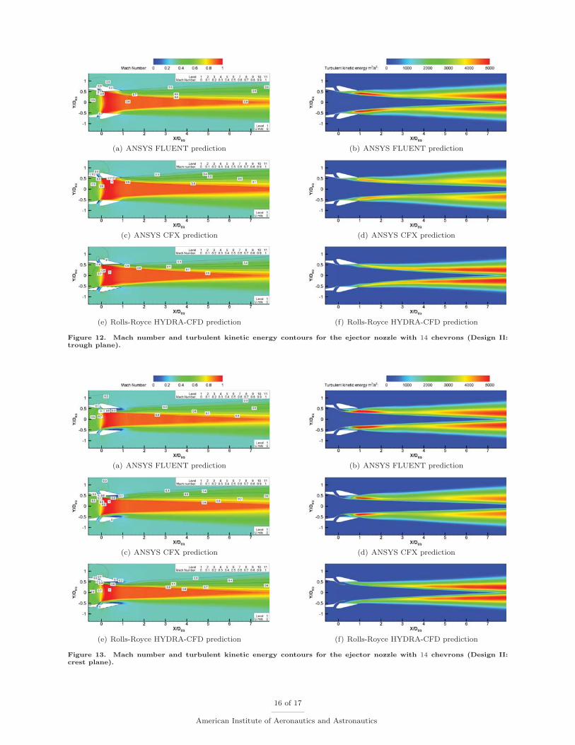
Design II is based on the dimensions for 14 chevrons. The presence of the clamshell door-supports allow theplacement of only 10 chevrons. Design II is different from Design I in the sense that the chevron-trough isaligned with the nozzle Z=0 symmetry plane. This results in a clocking of the vortices so that high speed flowis entrained into the shear layer on the plane where the maximum flow separation is present. Figure 12 showsthe contours of Mach number and turbulent kinetic energy on the symmetry plane. The flow separation,observed in the case of the baseline nozzle and Design I, is completely removed in the chevron-trough planebecause of the attachment of the shear layers. On the chevron-crest plane, a region of flow separation isobserved as shown in Figure 13. Therefore, the flow separation zone observed in Design I is redistributedand divided into two smaller zones by increasing the number of chevrons from 12 to 14.
Hence, it is concluded that the extent of flow separation and recirculation zone is decreased considerablywith the application of chevrons. Each chevron results in the formation of a counter-rotating vortex in thestreamwise direction which are of the shape of a kidney. This causes an enhanced mixing between the nozzleflow and the ejector flow and the shear layer spreads more outwards. The nozzle flow stays attached to theclamshell’s inner surface entirely on the chevron-trough plane and until around half the axial length of theclamshell doors on the chevron-crest plane. The recirculation zone is still present at the rear end of theclamshells. The effect of chevrons on the nozzle and ejector performance is discussed below.
B. Nozzle performance
One of the advantages associated with the ejector nozzle is the thrust augmentation. This is because of theaddition mass flow introduced into the primary nozzle flow through the ejector slots. Therefore, the thrustperformance of the ejector nozzle is dependent on the ejector flow. One of the objectives of this designstudy was to analyze the effect of chevrons on the ejector flow. It is observed that the addition of chevronsresulted in an increased nozzle-inlet mass flow by 10.7% for Design I and 9.4% for Design II. The reason forthis increased primary inlet flow is not well understood and is a topic which deserves further investigation.The addition of chevrons increased the primary nozzle exit area and this may be the reason for the abovementioned behavior. Table 3 shows a quantitative measure of the secondary flow, entrained into the primary
Table 3. The effect of chevrons on the entrained ejector mass flow.
Variables mej,min mej/min
Chevrons Flow Solvers FLUENT CFX HYDRA FLUENT CFX HYDRA
0 Inlet flow (kg/s) 57.737 57.914 58.003 0.1697 0.1736 0.2006Ejector flow (kg/s) 9.802 10.053 11.637
12 Inlet flow(kg/s) 63.893 64.851 63.940 0.1381 0.1258 0.0943Ejector flow(kg/s) 8.829 9.334 6.029
14 Inlet flow(kg/s) 63.158 63.819 63.567 0.1559 0.1582 0.0955Ejector flow(kg/s) 9.844 10.100 6.073
nozzle flow for the baseline ejector nozzle, the ejector nozzle with 12 chevrons and the ejector nozzle with14 chevrons. The ejector performance is represented by the ratio of the secondary mass flow entrainedthrough the ejector slot (mej) to the primary nozzle mass flow (min). It was observed that the increase inthe number of chevrons from 12 to 14 resulted in an improved mass entrainment because of the enhancedmixing. However, the mass entrainment was diminished in the case of 12 and 14 chevrons when comparedwith the baseline design. The reason behind this flow phenomenon was not well understood.
The nozzle performance predictions using ANSYS FLUENT and ANSYS CFX are in good agreementwith each other. The HYDRA-CFD flow solver predicts low secondary mass entrainment when comparedwith the other two solvers. This may be because of the application of the k-ε turbulence model in HYDRAcompared to the k-ω SST turbulence model in FLUENT and CFX.
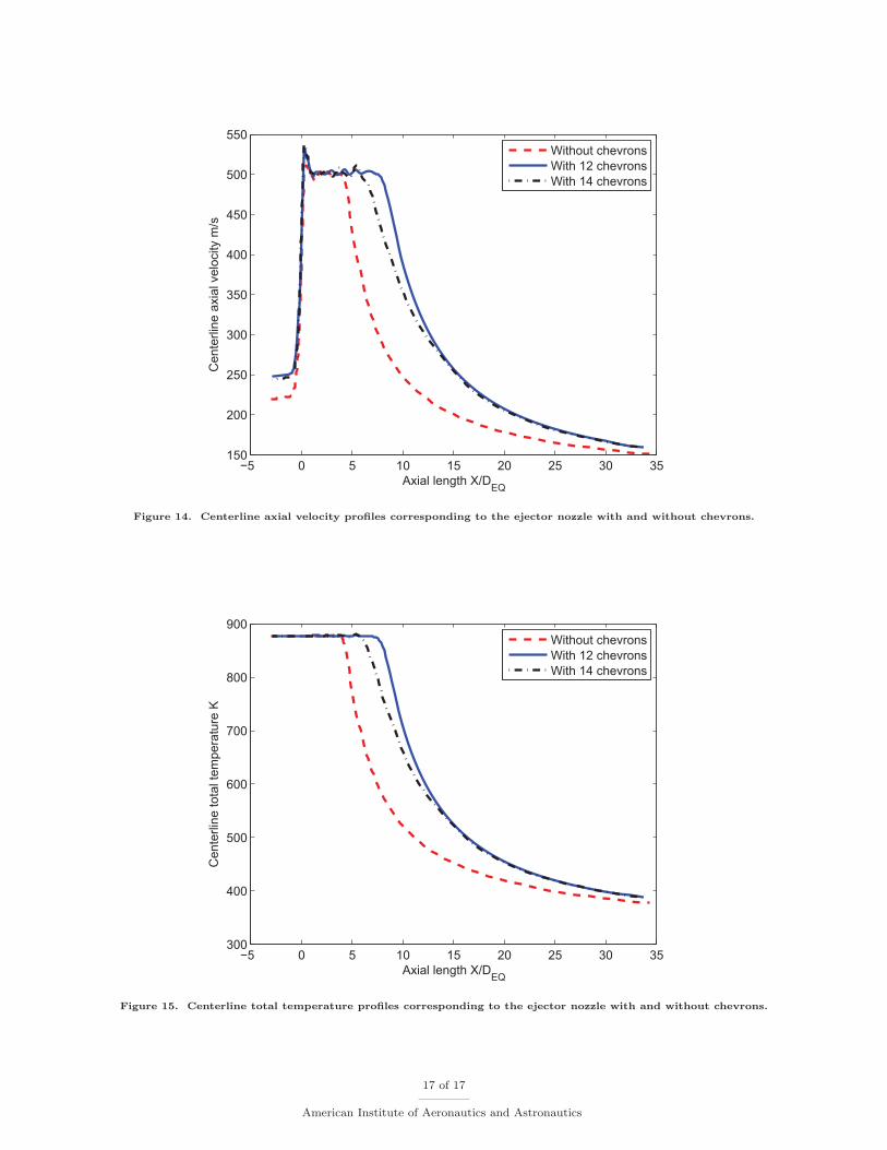
1. Discussion on the centerline statistics
Nozzle flow variables along the nozzle-axis are of utmost importance in understanding the characteristics ofthe jet. Figure 14 shows the distribution of the centerline velocity magnitude with respect to the normalized
8 of 17
American Institute of Aeronautics and Astronautics
axial distance along the streamwise direction, obtained by the application of the ANSYS FLUENT solver.The fundamental characteristics of jet flows such as the constant velocity potential core and inverse-spreadingof the jet with respect to axial distance are well captured. The oscillations in the potential core region showsthe presence of weak Mach waves. It was observed that the length of the potential core was longer forthe chevron nozzle when compared with the baseline nozzle. This may be because of the reason that theseparated jet flow in the baseline case pushes the streamlines closer creating a smaller jet; and thereforea shorter jet potential core length. In conclusion, this issue of longer potential core length in the case ofchevrons when compared with the baseline design is not well understood.
The variation of the total temperature with respect to the axial distance is shown in Figure 15. Increasingthe number of chevrons from 12 in Design I to 14 in Design II resulted in enhanced mixing. This is evidentfrom the decrease in the length of the potential core for Design II when compared with Design I.
VII. Conclusions
The computational simulation of the ejector nozzle was successfully carried out at flight conditions. Thepresent design of the ejector nozzle with clamshells showed a recirculation zone at the inner surface of theclamshells. The preliminary design of the ejector nozzle with clamshells and chevrons was completed andthe computational results obtained by the CFD simulations were discussed. In general, good agreementwas obtained among ANSYS FLUENT, ANSYS CFX and Rolls-Royce HYDRA-CFD code. Low massentrainment was predicted in the case of HYDRA-CFD which may be associated with the difference in theturbulence model used.
Two configurations with a different number of chevrons were designed and their computational simulationswere performed. Design I consisted of 12 chevrons which resulted in the alignment of the chevron-crest planewith the Z=0 symmetry plane. Design II consisted of 14 chevrons and ensured that the chevron-troughplane was aligned with the Z=0 symmetry plane. A reduction in the extent of flow separation was observedin both Design I and Design II when compared with the baseline ejector nozzle. The addition of chevronsshowed decreased ejector performance when compared with the baseline ejector nozzle. There is also anincrease in the length of the potential core for ejector nozzles with chevrons. This phenomenon is not wellunderstood and deserves further investigation.
Acknowledgments
This work was a part of the supersonic business jet program, sponsored by Rolls-Royce and the GulfstreamAerospace Corporation. The authors would like to thank Rolls-Royce and Gulfstream Aerospace Corporationfor publication approval.
References
1Whurr, J., “Propulsion System Concepts and Technology Requirements for Quiet Supersonic Transports,” InternationalJournal of Aeroacoustics, Vol. 3, No. 3, 2004, pp. 259–270.
2Thirumurthy, D., Design and Analysis of Noise Suppression Exhaust Nozzle Systems, Master’s thesis, School of Aero-nautics & Astronautics, Purdue University, West Lafayette, Indiana, USA, May 2010.
3Jones, J., Wind Tunnel Testing of a Supersonic Cruise Nozzle in Subsonic Ejector Configuration, Master’s thesis, Schoolof Aeronautics & Astronautics, Purdue University, West Lafayette, Indiana, USA, May 2009.
4Kapilavai, D., Tapee, J., Sullivan, J., Merkle, C. L., Wayman, T. R., and Conners, T. R., “Experimental Testing andNumerical Simulations of Shrouded Plug Nozzle Flow-fields,” 45th AIAA/ASME/SAE/ASEE Joint Propulsion Conference &Exhibit , Denver, CO, USA, August 2009, AIAA-2009-4902.
5Stitt, L. E., “Exhaust Nozzles for Propulsion Systems with Emphasis on Supersonic Cruise Aircraft,” Tech. Rep. RP-1235,NASA, May 1990.
6Khalid, S., Sokhey, J., Chakka, P., and Pierluissi, A., “Ejector/Engine/Nacelle Integration for Increased Thrust minusDrag,” 46th AIAA/ASME/SAE/ASEE Joint Propulsion Conference and Exhibit , Nashville, TN, USA, June 2010, AIAA-2010-6501.
7Thirumurthy, D., Jones, J., Blaisdell, G., Lyrintzis, A., and Sullivan, J., “Experimental Investigation and Computationof a Supersonic Ejector Nozzle with Clamshells,” 40th AIAA Fluid Dynamics and Applied Aerodynamics Conference, Chicago,IL, USA, June 2010, AIAA-2010-4575.
8Der, J. J., “Improved Methods of Characterizing Ejector Performance,” Journal of Propulsion and Power , Vol. 7, No. 3,1991.
9 of 17
American Institute of Aeronautics and Astronautics
9Lighthill, M. J., “On Sound Generated Aerodynamically I: General Theory,” Proceedings of the Royal Society of London,Vol. 211, No. 1107, 1952, pp. 564–587.
10Saiyed, N., Mikkelsen, K., and Bridges, J., “Acoustics and Thrust of Separate-Flow Exhaust Nozzles with Mixing Devicesfor High-Bypass-Ratio Engines,” 8th AIAA/CEAS Aeroacoustics Conference and Exhibit, Lahaina, Hawaii, USA, June 2000,AIAA-2000-1961.
11Kenzakowski, D. C., Shipman, J., Dash, S. M., Bridges, J., and Saiyed, N. H., “Study of Three-Stream Laboratory Jetswith Passive Mixing Enhancements for Noise Reduction,” 38th AIAA Aerospace Sciences Meeting and Exhibit, Orlando, FL,USA, January 2000, AIAA-2000-0219.
12Bridges, J. and Brown, C. A., “Parametric Testing of Chevrons on Single Flow Hot Jets,” 10th AIAA/CEAS AeroacousticsConference and Exhibit , Manchester, UK, May 2004, AIAA-2004-2824.
13Janardan, B. A., Hoff, G. E., Martens, S., Mengle, V., and Dalton, W. N., “AST Critical Propulsion and Noise ReductionTechnologies for Future Commercial Subsonic Engines,” Tech. Rep. CR-2000-210039, NASA, December 2000.
14Pointwise, Inc., Fort Worth, TX, GRIDGEN v15.09 User Manual , 2006.15ANSYS, Inc., Lebanon, NH 03766, USA, ANSYS FLUENT v6.3 User Guide, 2006.16ANSYS, Inc., Pittsburgh, PA, USA, ANSYS CFX Release 12.1 User Guide, 2009.17Lapworth, B. L., “HYDRA-CFD: A Framework for Collaborative CFD Development,” International Conference on
Scientific and Engineering Computation (IC-SEC), Singapore, June, 2004.18Menter, F., “Two-Equation Eddy-Viscosity Turbulence Models for Engineering Applications,” AIAA Journal , Vol. 32,
No. 3, March 1994, pp. 1598–1605.19Moininer, P., Muller, J. D., and Giles, M. B., “Edge-based Multigrid Schemes and Preconditioning for Hybrid Grids,”
AIAA Journal , Vol. 40, No. 10, 2002, pp. 1954–1960.20Martinelli, L., Calculations of Viscous Flows with a Multigrid Method , Ph.D. thesis, Department of Mechanical and
Aerospace Engineering, Princeton University, Princeton, USA, 2010.
10 of 17
American Institute of Aeronautics and Astronautics
(a) (b)
Figure 1. (a). A schematic representation of an airbreathing turbofan engine showing the ejector nozzle with clamshelldoors,1 (b). CAD model of the 3-D ejector nozzle with clamshell doors.
(a)
(b)
Figure 2. (a). Transverse flow jet survey with velocity fluctuation contours at X/DEQ=1.0 for the ejector nozzle with
clamshells showing regions of reverse flow,7 (b). Computational axial velocity contours on the Z = 0 symmetry planefor the ejector nozzle with clamshells showing reverse flow using negative axial velocity contour lines.7
11 of 17
American Institute of Aeronautics and Astronautics
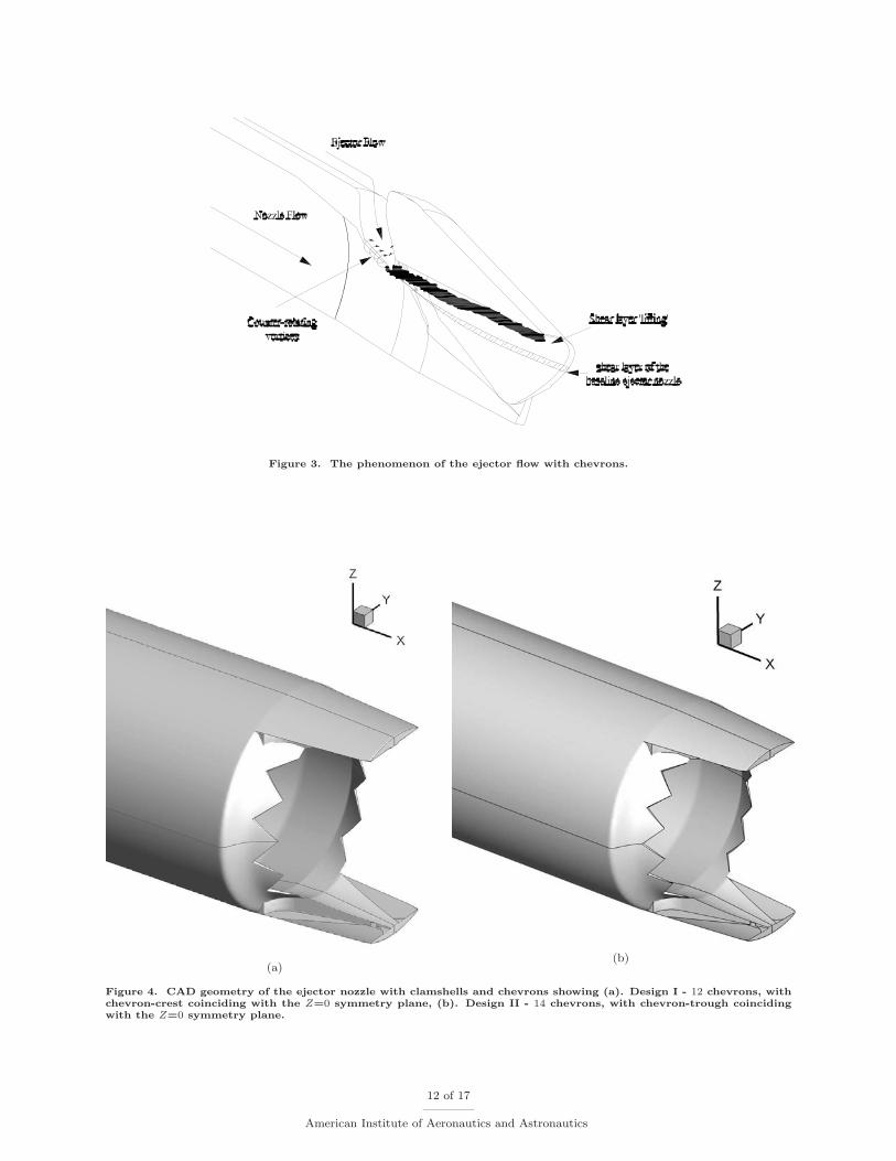
Figure 3. The phenomenon of the ejector flow with chevrons.
(a)(b)
Figure 4. CAD geometry of the ejector nozzle with clamshells and chevrons showing (a). Design I - 12 chevrons, withchevron-crest coinciding with the Z=0 symmetry plane, (b). Design II - 14 chevrons, with chevron-trough coincidingwith the Z=0 symmetry plane.
12 of 17
American Institute of Aeronautics and Astronautics

(a)(b)
Figure 5. Computational mesh for the ejector nozzle wall and chevrons corresponding to (a). Design I (based on 12chevrons.), (b). Design II (based on 14 chevrons.).
Figure 6. The control volume architecture of ANSYS FLUENT (cell center), ANSYS CFX (cell vertex) and Rolls-RoyceHYDRA-CFD (median-dual volume).
Figure 7. Contours of Mach number and turbulent kinetic energy corresponding to the CFD simulation of the baselineejector nozzle.
13 of 17
American Institute of Aeronautics and Astronautics
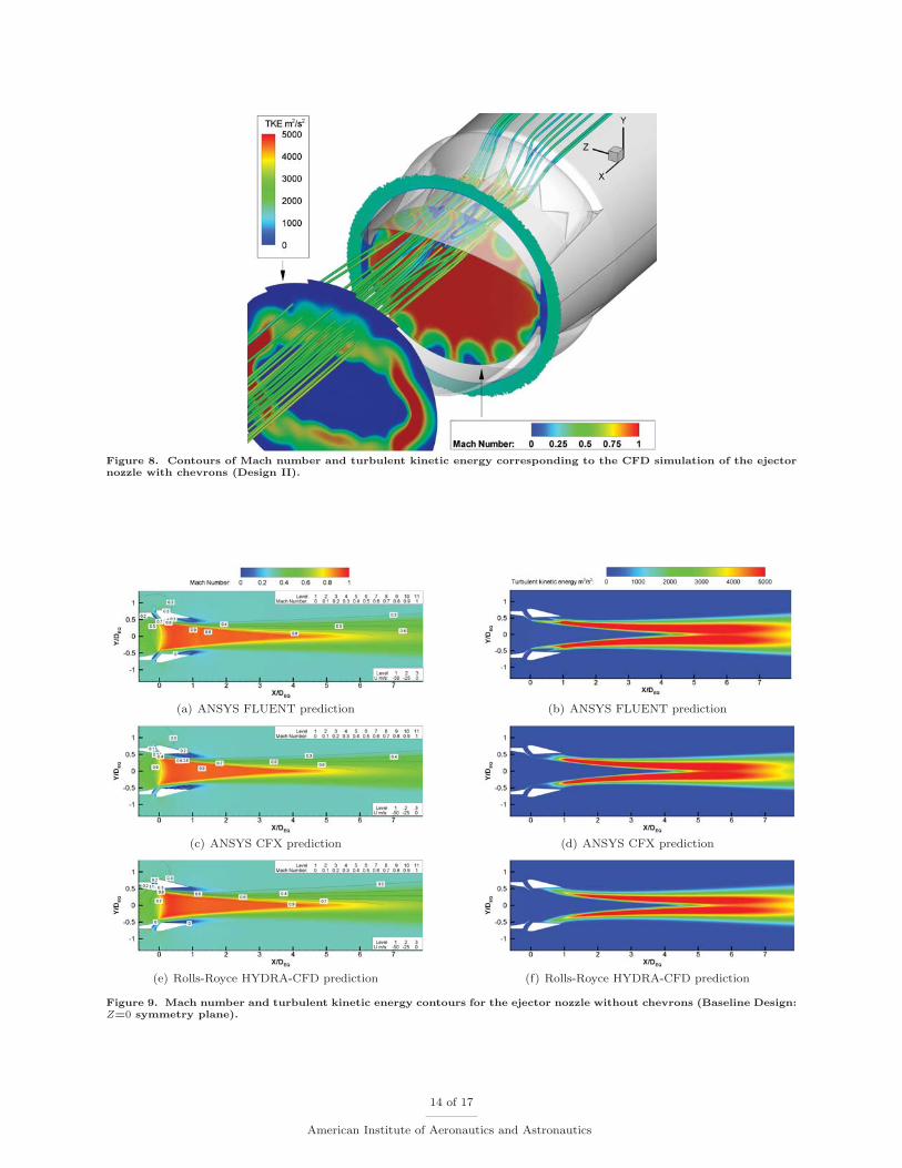
Figure 8. Contours of Mach number and turbulent kinetic energy corresponding to the CFD simulation of the ejectornozzle with chevrons (Design II).
(a) ANSYS FLUENT prediction (b) ANSYS FLUENT prediction
(c) ANSYS CFX prediction (d) ANSYS CFX prediction
(e) Rolls-Royce HYDRA-CFD prediction (f) Rolls-Royce HYDRA-CFD prediction
Figure 9. Mach number and turbulent kinetic energy contours for the ejector nozzle without chevrons (Baseline Design:Z=0 symmetry plane).
14 of 17
American Institute of Aeronautics and Astronautics

(a) ANSYS FLUENT prediction (b) ANSYS FLUENT prediction
(c) ANSYS CFX prediction (d) ANSYS CFX prediction
(e) Rolls-Royce HYDRA-CFD prediction (f) Rolls-Royce HYDRA-CFD prediction
Figure 10. Mach number and turbulent kinetic energy contours for the ejector nozzle with 12 chevrons (Design I: crestplane).
(a) ANSYS FLUENT prediction (b) ANSYS FLUENT prediction
(c) ANSYS CFX prediction (d) ANSYS CFX prediction
(e) Rolls-Royce HYDRA-CFD prediction (f) Rolls-Royce HYDRA-CFD prediction
Figure 11. Mach number and turbulent kinetic energy contours for the ejector nozzle with 12 chevrons (Design I:trough plane).
15 of 17
American Institute of Aeronautics and Astronautics
(a) ANSYS FLUENT prediction (b) ANSYS FLUENT prediction
(c) ANSYS CFX prediction (d) ANSYS CFX prediction
(e) Rolls-Royce HYDRA-CFD prediction (f) Rolls-Royce HYDRA-CFD prediction
Figure 12. Mach number and turbulent kinetic energy contours for the ejector nozzle with 14 chevrons (Design II:trough plane).
(a) ANSYS FLUENT prediction (b) ANSYS FLUENT prediction
(c) ANSYS CFX prediction (d) ANSYS CFX prediction
(e) Rolls-Royce HYDRA-CFD prediction (f) Rolls-Royce HYDRA-CFD prediction
Figure 13. Mach number and turbulent kinetic energy contours for the ejector nozzle with 14 chevrons (Design II:crest plane).
16 of 17
American Institute of Aeronautics and Astronautics
−5 0 5 10 15 20 25 30 35150
200
250
300
350
400
450
500
550
Axial length X/DEQ
Cen
terli
ne a
xial
vel
ocity
m/s
Without chevronsWith 12 chevronsWith 14 chevrons
Figure 14. Centerline axial velocity profiles corresponding to the ejector nozzle with and without chevrons.
−5 0 5 10 15 20 25 30 35300
400
500
600
700
800
900
Axial length X/DEQ
Cen
terli
ne to
tal t
empe
ratu
re K
Without chevronsWith 12 chevronsWith 14 chevrons
Figure 15. Centerline total temperature profiles corresponding to the ejector nozzle with and without chevrons.
17 of 17
American Institute of Aeronautics and Astronautics