preliminary structural evaluation and presentation …report· usher mill structural evaluation 8 1...
TRANSCRIPT

Alexander C. Schreyer, M.A.Sc., Dipl.Ing. (FH)
Preliminary Structural Evaluation and Presentation of Refurbishment Options for the
Usher Mill in Erving, MA
Report – August 2003
Building Materials and Wood Technology
University of Massachusetts, Amherst, MA
© 2003, A. Schreyer, UMass Amherst

Report· Usher Mill Structural Evaluation
2
Disclaimer The author of this report is not a registered professional engineer in Massachusetts. As such, all structural assessments and recommendations conveyed in this report are solely preliminary in nature. Findings and suggestions are non-binding and only for estimation purposes. All structural assessments and recommendations must be reviewed and finalized by a registered professional engineer before they are implemented or acted upon. The author of this report does not assume any liability for direct or indirect damages and claims deriving from this work.
Within the scope of this assessment, it is not possible to warrant the correctness, value and sufficiency of all cost estimates.
Contact:
Alexander C. Schreyer, M.A.Sc., Dipl.-Ing. (FH) Graduate Research Assistant / Lecturer
Mail: University of Massachusetts Building Materials & Wood Technology Department of Natural Resources Conservation 160 Holdsworth Way Amherst, MA 01003-9285
E-Mail: [email protected]
Website: www.alexschreyer.de

Report· Usher Mill Structural Evaluation
3
Executive Summary This report provides a preliminary structural evaluation of the Usher Mill buildings which are located in the center of Erving, Massachusetts. Furthermore, it offers refurbishment options together with associated cost estimates.
All investigations were based on data gathered during a set of visits to the buildings where these were surveyed and structural damages were evaluated and charted (for most buildings). In addition, a preliminary structural analysis of all wooden members in buildings 1, 2 and 6 was performed according to current design standards. Finally, construction costs were estimated using common costing handbooks and contractors’ and manufacturers’ budgets.
It was determined that buildings 1, 2 and 3 on the Usher Mill site represent typical industrial structures from the beginning of the 20th century. In addition, lesser quality buildings dating from the middle of that century also exist on the site. Architecturally, the most interesting structures are buildings 1, 2 and 3. Existing structural collapses and overall architectural layout suggest that buildings 4, 5 and 7 have no remaining value and should be demolished. Possible re-uses of buildings 1 and 2 were determined to be ranging from office / residential to retail / light industry. Due to their layout, buildings 3 and 6 were not considered as being able to provide office / residential re-uses.
All buildings were found to be in a damaged but savable condition. Structural damages range from moisture-related mold problems in buildings 1, 2 and 6 to rust-induced steel collapses in building 5. Masonry (walls) and concrete (walls and slabs) were generally found to be in good condition although some repair will be necessary on the exterior faces.
It was determined that the sole cause for the current state of structural deterioration of most of the buildings was the negligence to maintain a sound enclosure after the buildings had been vacated. Roof leaks as well as vandalized windows allowed the uncontrolled intrusion of water into the structures and caused deterioration of the wooden members in buildings 1, 2 and to a lesser extent 6. This deterioration was found to be more widespread in the lower floors than it was on the roof.
Structural deficiencies (partial or full) in buildings 1 and 2 were mainly located in the wooden beams and rafters and were found in at least 40-50% of all of those members. Columns were affected to a lesser degree, but moisture levels were found to be high enough that undiscovered deterioration at their bases would be likely.
Although building 3 did not appear to have suffered any structural damages, it was assumed that it contains Asbestos in its ceilings and pipe insulation, which would need to be removed. It was suggested that the extent of hazardous materials in all buildings would need to be evaluated before any final renovation cost estimate could be produced.
Three refurbishment options were presented for buildings 1 and 2. These consisted of either retaining the current structure and replacing its deteriorated parts (option 1/2.A) or removing the entire interior wooden structure and replacing it with a heavy-timber (option 1/2.B) or a light frame structure (option 1/2.C). Option 1/2.C effectively involved the creation of a separate building within the existing walls.
A structural analysis of buildings 1 and 2 showed that although the existing structure (if sound) would be able to carry loads (with minor limitations) from the 50 psf category that includes offices and residential uses, industrial or retail loads would not receive sufficient support unless the existing structure is either upgraded or its material is re-evaluated. The analysis of building 6 for re-
Report· Usher Mill Structural Evaluation
4
use with light industrial loads (125 psf) showed insufficient strengths in the floor as well as the roof beams. A new structural system using a wood-concrete composite floor was presented as a possible structural upgrade for heavy-timber floors in buildings 1 and 2.
Cost estimates showed that option 1/2.A would be the most expensive (due to material inefficiencies and construction difficulties) and option 1/2.C would cost least to refurbish buildings 1 and 2. Since building 6 showed only minor damages, repair and replacement of the deteriorated structural members was the only investigated option for refurbishment. Although this solution is quite cost efficient, any future reuse of building 6 would be determined more by its accessibility and its necessary architectural improvements than by its structural upgrades.
Although demolition of the entire site was estimated at $ 420,000, it was assumed that this figure would have to be corrected upward if hazardous waste (Asbestos, etc.) removal was included. Also, it is expected that mothballing of the buildings that are deemed to be redeveloped will have to occur in any case since the timeframe until reconstruction commences may be quite long.
Although it is likely that any development on the site will be influenced by the Rivers Protection Act, redevelopment as well as new construction should not be hindered by it.
It was suggested that any final structural concept for the remaining buildings should use floor load categories that allow for a flexible use of the interior space.

Report· Usher Mill Structural Evaluation
5
Table of Contents Disclaimer.........................................................................................................................................................2 Executive Summary ........................................................................................................................................3 Table of Contents............................................................................................................................................5 Acknowledgements .........................................................................................................................................7 1 Introduction ..........................................................................................................................................8
1.1 Project Context................................................................................................................................8 1.2 Rivers Protection Act Issues .......................................................................................................10 1.3 Scope...............................................................................................................................................10
2 Description of Site .............................................................................................................................12 2.1 Structural Systems of Buildings...................................................................................................13 2.2 Historic Considerations................................................................................................................18
3 Current Structural Condition............................................................................................................21 4 Options for Action.............................................................................................................................28
4.1 Refurbishment Options ...............................................................................................................28 4.1.1 Buildings 1 and 2 ...................................................................................................................29 4.1.2 Building 3................................................................................................................................32 4.1.3 Building 6................................................................................................................................32 4.1.4 Mothballing.............................................................................................................................33
4.2 Problems due to Fungal Infestation...........................................................................................34 4.3 Preliminary Structural Analysis ...................................................................................................35
4.3.1 Buildings 1 and 2 ...................................................................................................................35 4.3.2 Building 6................................................................................................................................36 4.3.3 Strengthening of Wood Members.......................................................................................37
5 Cost Estimation ..................................................................................................................................38 5.1 Refurbishment...............................................................................................................................39 5.2 Demolition / Deconstruction and Mothballing.......................................................................41
6 Conclusions and Recommendations ...............................................................................................42 6.1 Required Immediate Actions.......................................................................................................44
References and Further Reading.................................................................................................................45 Appendix A – Plans of Usher Mill Site and Buildings.............................................................................47 Appendix B – Plans of Condition of Structural Members......................................................................48

Report· Usher Mill Structural Evaluation
6
Appendix C – Estimating Data ...................................................................................................................49

Report· Usher Mill Structural Evaluation
7
Acknowledgements Thanks to Rebecca Loveland, James Palma, Alexandra Proshina, Robert Lacey and Pamela Miller from the Donahue Institute at the University of Massachusetts Amherst for their help during the walk-through.
Thanks also to R. Bruce Hoadley, Professor in Building Materials and Wood Technology at the University of Massachusetts, Amherst for his help in identifying the wood samples.
The following companies provided cost estimates which were verified (and modified where necessary) and included into the estimates presented in this report. Mention of any of these companies does not constitute an endorsement of their services or products.
Demolition:
Associated Building Wreckers 352 Albany St. Springfield, MA 01101 1-800-448-2822
Heavy-Timber (new and recycling):
Bensonwood Homes 6 Blackjack Crossing Walpole, NH 03608 1-603-756-3600
Engineered Wood Products:
TrusJoist, A Weyerhaeuser Business 460 Smith St. Suite C Middletown, CT 06457 1-860-635-7999

Report· Usher Mill Structural Evaluation
8
1 Introduction This preliminary structural evaluation and presentation of refurbishment options for the Usher Mill in Erving, Massachusetts is part of a larger planning project conducted and coordinated by the Donahue Institute at the University of Massachusetts. The entire project is based on a Massachusetts planning grant, which, under Executive Order 418, awards towns and cities up to $ 30,000 to create a Community Development Plan. Ultimately, the development of such a plan is intended to aid in the establishment of a full Master Plan (Erving has completed this in 2002).
Located in the center of Erving, the now deteriorating structures that make up the Usher Mill complex belong to one of four mills that are still in existence in this traditional New England industrial town. Of these, only two are currently in use: the new Erving Paper Mill and the “Renovator’s” Mill that has been redeveloped and rededicated as a home of Renovator’s Supply. Of the remaining two mills, the International Paper Mill was vacated recently and remains boarded up. The most crucial issue in the re-use of the Usher Mill is the fact that it was never properly boarded up, which permitted its enclosure to be vandalized and – together with roof problems – allowed the structure to deteriorate in an uncontrolled fashion.
In considering a re-use of the currently abandoned structures, it is important to recognize the advantages that their location presents. Having been built directly on the banks of Miller’s River, between two state forests and almost adjacent to Route 2, accessibility in combination with already existing recreational activities should be able to offer this site a demand for a whole range of re-use options.
It was identified early on during the investigation of development options for Erving (Hoke et al., 2000) that one of the most crucial points would be an assessment of the condition and reusability of the Usher Mill site. In combination with an environmental assessment of the site, a structural assessment of all buildings was identified as an immediate requirement.
This report provides a preliminary structural evaluation of the Usher Mill buildings and presents refurbishment options together with associated cost estimates. Although it was attempted to offer enough information to allow an educated decision to be made on the viability of any re-use (or demolition), the reader has to keep in mind that unless the environmental questions (possible soil contamination, asbestos in buildings, etc.) have been answered and an overall master plan has been created (by an architectural consultant), the final costs and efforts can only roughly be estimated.
1.1 Project Context The town of Erving, which is currently home to almost 1,500 inhabitants, is a traditional Massachusetts town with an industrial heritage. Its location on Miller’s River fostered industrial production for the major part of the last two centuries (and in the case of the current Erving Paper Mill still does today). As shown by Mattos (2002), Erving paid for its high economic dependency on manufacturing with a jump in unemployment in the early 1990s when the old Erving Mill plant closed. Together with other mill closings, local unemployment increased and today, Erving provides a location for only 357 jobs (2001 figure). This fate is typical for old manufacturing towns in Massachusetts that suffered from an overall cost-driven shift away from low-value manufacturing which occurred over the last decades in the United States.

Report· Usher Mill Structural Evaluation
9
Erving, which is included on Massachusetts’ list of Economically Distressed Areas is also typical for local manufacturing towns in that it has a set of old mills that (for several reasons) have been abandoned by the former owners. Fear (and likely knowledge) of hazardous materials problems on these old mill sites together with insufficient public funding for cleanup left many mill sites unsellable and only created financial burdens for the owners. As a result, any re-use will have to be founded on a solid financial framework based on private as well as public funds and will need to be fully supported by local town governments through tax incentives and an overall tolerant attitude towards any developer.
Redeveloping old mill sites involves a host of regulatory and technological challenges. Regulatory challenges arise from building code requirements, site accessibility, fire and hazardous materials legislation. Also, the Wetlands Protection Act (MGL, Ch. 131, §40) puts limits on new construction next to rivers and prohibits any new runoff (see next chapter). Related to the technological challenges are problems of structural integrity and building performance. All of these challenges make it easier for any industrial developer to eye an undeveloped green field before looking at redeveloping an old building. Nevertheless, current Massachusetts brownfields legislation (Mattos, 2002) provides options that ease regulatory issues for owners and potential developers. Cleanup funding is also available under certain circumstances. In any case, developing an old mill can be rewarding if location, historic value and public demand create economic incentives to do so.
Successful mill redevelopments can be found all over Massachusetts. High profile examples of these are the historic mills in Lowell or the Sprague Mill in North Adams that now houses Mass MoCA, a contemporary art exhibition space (Figure 1; see also Mass MoCA, 2000). More locally, the “Renovator’s” Mill between Erving and Miller’s Falls is an example of such a rededication of an old building.
Figure 1 - Mass MoCA Interior (Café)
Structurally, historic mill buildings in Massachusetts are in a whole range of conditions. While some continuously occupied mills still are in good and easily upgradeable shape, early abandoned buildings were simply left to deteriorate. Main challenges that are being faced derive from the question of which historic structural elements are worth keeping and which need to be repaired or

Report· Usher Mill Structural Evaluation
10
replaced. In some cases, an entire replacement of the main structural system is necessary while in others, cleaning may be all that is required. If desired, existing structural systems can even be completely reconfigured as can be found in some of the tall gallery spaces at Mass MoCA.
Also, the kind of re-use largely determines the choice of structural and architectural solutions. While an artists’ space, such as Mass MoCA, accepts and maybe even desires a rougher, unfinished look (which is cheaper to achieve) then a minimal repair of the existing structure might be a viable solution. If, however, as in the case for elderly housing, a whole range of amenities and services are required, then this may need a more thorough refurbishment approach.
1.2 Rivers Protection Act Issues The Rivers Protection Act, which is part of the Massachusetts Wetlands Protection Act (MGL, Ch. 131, §40), is a legislative framework designed to prevent any kind of environmental dangers to rivers and their ecosystem, which would arise from adjacent land uses. As such, it curtails new development close to rivers and prohibits runoff into streams.
In its exact terms, this law prohibits new construction within a band that extends 200 ft from either side of a river’s mean annual high water level. Fortunately (and surely to foster cleanup of existing mill sites), riverfront areas that are or have been occupied by historic mill complexes (which were in existence before 1946) are exempt from this legislation. As a result, rehabilitation and likely new construction are possible on the grounds of any mill building in Massachusetts.
Since the implementation of this law is handled by a city- or town-level Conservation Commission, it is important that any development has the full support of the townspeople. If any disagreement exists between a developer and a Conservation Commission, the Department of Environmental Protection provides a higher-level ruling body (Jackson, 2003).
1.3 Scope The main goal of this report is to provide a preliminary (“phase one”) assessment of the structural condition of the Usher Mill site in Erving, Massachusetts. Key structural problems relevant to the oldest buildings on the site (buildings 1, 2 and 3) as well as the warehouse (building 6) on the far end of the site have been identified. Resulting from this, a discussion of potential rehabilitation options and strategies has been initiated. Finally, estimates for the cost of structural rehabilitation of these buildings for different types of uses as well as their demolition have been presented. Where necessary, the need for further investigations has been discussed.
Although the condition of all structural and non-structural elements is reported (where feasible), the main focus has been the wooden members (beams, joists, columns). Also, architectural elements such as doors, windows, partitions, finishes, utilities etc. as well as non-structural building performance criteria such as egress, lighting, fire protection, energy conservation etc. have not been considered in the discussion of cost estimates since they are not part of a structural assessment.

Report· Usher Mill Structural Evaluation
11
This report focuses on conversions of the existing structures to possible end-uses as follows:
1. Housing
2. Commercial / retail / office space
3. Light industrial use
4. Mixed use
5. Mothballing
6. Demolition
In the creation of this report, it was assumed that buildings 4 (kilns) and 7 (gymnasium) as well as possibly building 5 (the atrium) would be demolished in any case due to existing structural collapses and lack of potential for reasonable use.

Report· Usher Mill Structural Evaluation
12
2 Description of Site The User Mill site is located on 5.76 acres of land adjacent to Miller’s River, immediately off Route 2 and near the center of Erving, Massachusetts. The property is bounded by the Boston & Maine Railroad in the north and Miller’s River in the south.
Structures on the site are all located west of Arch Street and include seven buildings which are connected either by abutting each other or through ramps and passageways. Figure 2 shows an overview of these buildings. In addition to these structures, parking areas and utility items such as a water tower and small sheds also exist on the opposite side of Arch Street in the east.
The area occupied by buildings measures approximately 69,000 sq ft (excluding loading docks and ramps). If the various floors are considered, a total enclosed floor area of approximately 87,000 sq ft is available. The enclosed space measures approximately 1,340,000 cu ft.
Figure 2 - Structures on the Usher Mill Site (1/2: Offices, Manufacturing;
3: Boiler House; 4: Kilns; 5: Atrium; 6: Warehouse; 7: Gymnasium)
Structural systems, building materials and structural quality vary considerably throughout the array of buildings. Due to continuing expansion and obvious rededications, buildings were added on or modified using building practices that were common at the time of construction. This led to some degree to a decreasing trend of quality over time.
Buildings 1, 2 (offices and manufacturing) and 3 (boiler room and smokestack) are the oldest structures on the site dating from 1918. The kilns (building 4), the enclosed courtyard (building 5) and the warehouse (building 6) were added in 1948 (Hoke et al. 2000). No construction date could be determined for building 7.
Detailed drawings of all surveyed buildings can be found in Appendix A. A textual summary is presented in the following chapter.
Since measurements were taken of an old structure (which is inherently somewhat irregular), all dimensions that are mentioned in this report and its accompanying plans represent actual dimensions, not nominal values.

Report· Usher Mill Structural Evaluation
13
2.1 Structural Systems of Buildings Building 1:
This building’s footprint has a rectangular shape measuring approximately 60 ft x 100 ft. It features two floors over an enclosed basement which yields an approximate overall height above ground of 30 - 35 ft.
The main supporting structure consists of red-brick masonry perimeter walls and a heavy-timber Southern Yellow Pine post-and-beam structure on the inside. The roof is built as a flat-roof and is minimally sloped from a central N-S apex towards both outside walls at approx. 3º.
The brick walls, which are 16 in thick, feature stepped-back sections (12 in thick) containing large multiple-pane windows spaced at 7 ft (E, W walls) and at approx. 9-½ ft (N, S walls) on center. Contrasting to the upper floors, the basement walls (thickness: 16 in) are concrete and only feature small openings.
The heavy-timber structure consists of 9-½ in x 9-½ in columns on the first floor and 7-½ in x 7-½ in columns on the second. Floor beam cross-sections vary from 11-½ in x 15 in to 13-½ in x 17 in on the second floor and 7-½ in x 12-½ in to 7-½ in x 14 in on the roof. Although the basement could not be surveyed, observations from building 2 indicate that the first floor beams measure 11-½ in x 15-½ in.
Columns are spaced at a 14 ft x 19 ft – 3-½ in grid and beams span between 14 ft (longitudinal headers) and approx. 18 ft – 7 in (outside field). All second floor and roof beams appear to be single-span systems bearing either on steel shoes or directly on top of the columns. At the outside walls, beams frame into the masonry for an unspecifiable distance. A ventilation space around these bearings is notably absent.
Both floors as well as the roof feature tightly laid 3 in x 7 in timber decking which appears to be continuous over at least two fields (2x 7 ft spans). This, however, could not be verified due to additional floor covering.
Figure 3 - Building 1: Outside View; Second Floor
Since the basement of this building could not be surveyed, it can only be assumed that it is constructed similarly to the basement of building 2.

Report· Usher Mill Structural Evaluation
14
Due to the existence of building 7, all first-floor windows on the western wall are enclosed with infill concrete-block masonry.
Building 2:
This building is identical to building 1 in its structural features and system. Differences arise mainly from the changed orientation (E-W) and the size: Building 2 is twice as long as building 1 yielding a 200 ft x 60 ft footprint. This also explains the existence of an interior masonry wall in the center of the building, which divides it into two 100 ft long parts. Adjacent to this wall are two masonry shafts: One on the north side containing a freight elevator and one on the south side containing rooms and electrical services.
Figure 4 - Building 2: Outside View; First Floor
Figure 5 - Building 2: Basement
The basement of this building was partially examined, which revealed concrete columns supporting the first floor beam structure. Column diameters are either 12 in x 24 in (below beams) or 27-½ in x 27-½ in (below columns). These columns are resting on irregularly shaped concrete foundations (which could not be evaluated further). Some portions of the basement also feature concrete-block masonry walls directly below first floor beams as well as round steel tube columns

Report· Usher Mill Structural Evaluation
15
on the north side of the building. The basement floor consists of a concrete slab of an unspecifiable thickness.
Similar to building 1, all windows facing the atrium (building 5) are enclosed by concrete-block masonry infill.
Building 3:
This building has a rectangular footprint measuring approx. 81 ft x 92 ft. It is divided in the N-S direction into two bays of 38 ft – 2 in internal width, which in turn are divided by masonry walls into two larger and two smaller rooms.
The structure of this building consists of red-brick masonry exterior walls similar to buildings 1 and 2 and Pratt-type steel roof trusses spanning E-W spaced at 10 ft. The sloped roof features apex skylights in all four rooms and is covered with what appears to be cementitious plates. Due to the use as a boiler building, it is very likely that these plates contain Asbestos.
The floor levels vary between the two bays. The eastern bay has a level similar to building 5, which allows for easy transition between them. The western bay contains a large boiler as well as the chimney (and their foundations). It has a floor level that is one story below the one of building 5 and is only accessible from the rear room by stairs. All floors consist of concrete slabs.
All windows facing buildings 5 and 7 have been enclosed by infill concrete-block masonry (except for door openings).
Figure 6 - Building 3: Boiler; Adjacent Room
Building 4:
This one-level structure has an irregular shape with a maximum N-S expanse of 154 ft and a maximum E-W dimension of 129 ft. It encloses long rooms (the kilns) which are bounded by long red-brick masonry walls extending north from a wide main E-W corridor (in extension of building 5).

Report· Usher Mill Structural Evaluation
16
Its structure consists of red-brick and concrete block masonry walls, steel columns and a beam-and-purlin timber roof. The roof is flat and decked in wood. Due to existing roof failures, no slope could be determined.
Figure 7 - Building 4: South-West Wall; Kiln Room
Building 5:
This is not a building per se since its perimeter consists mainly of the walls of surrounding buildings. Nevertheless, its roof creates an enclosed atrium linking buildings 1, 2, 3, 4 and 7. Building 5 has a length of 154 ft and a width varying from 31 ft to 40 ft. Its height is identical with the roof lines of buildings 1 and 2.
The roof structure of this building consists of parallel-chord open-web steel trusses spanning N-S at a spacing of 7 ft. These are covered by corrugated steel. The lower height of building 3 made it necessary to construct a steel support structure directly above its walls.
Figure 8 - Building 5: West View, East View

Report· Usher Mill Structural Evaluation
17
Building 6:
This building has a rectangular footprint of 150 ft x 122 ft less a triangular section in the south-west corner whose edges measure 22 ft and 54 ft. It encloses a large one-level open space and rests on concrete piers over an accessible mud crawlspace. A loading dock of approx. 50 ft x 34 ft is located adjacent to the north-west corner of this building.
The structure of building 6 consists of a post-and-beam Southern Yellow Pine timber frame with wooden floor and roof joists and wood decking. The foundation piers as well as the timber columns are arranged on a 13–½ ft x 11 ft grid.
Timber columns have a 7–½ in x 7–½ in cross-section and are 11 ft 1 in and 14 ft 6 in high at the lowest and highest points of the roof, respectively. Approximately 3 ft from their top, all columns also feature face-nailed knee-braces on two sides.
First floor beams measure 11 in x 13 in and run continuously over two fields in the N-S direction. First floor joists sit on top of the beams, run simply supported E-W and have a 2-½ in x 11-½ in cross section. They are spaced at 17-¾ in on center. In addition to the main floor beams, there also exists a set of beams running diagonally in one line across the entire building width. These beams frame into the main floor beams and rest on common or additional concrete or steel piers.
The roof is similarly built-up with main beams (6 in x 11-½ in) running N-S, diagonal beams (6 in x 11-½ in) and roof joists (2-½ in x 7 in and same spacing as floor joists) over which decking is laid. Some roof beams have received steel C-channel reinforcements on both sides. In addition, the roof features 11 shed dormers that face either east or west and provide the only natural light in the structure.
The foundation piers are concrete and measure 14 in x 14 in in their cross-section. Due to the sloping ground under the building, the perceivable height of these columns varies. In addition, a capped wood-pier support runs between the concrete piers in one field E-W across the entire building width.
Figure 9 - Building 6: Post-and-Beam Structure, Foundations

Report· Usher Mill Structural Evaluation
18
Building 7:
This building with a rectangular footprint of 30 ft x 100 ft is, similar to building 5 only an infill structure providing an enclosed space between existing walls. Its steel-beam roof structure rests directly on the western wall of building 1 and the eastern wall of building 3. In the north as well as the south end of building 7, concrete-block masonry walls have been erected to enclose it and provide support for the longitudinal roof beams. This building’s height is level with the outside wall of building 3 and measures approximately 20 ft.
The flat roof structure is made up of rolled steel beams spanning E-W and N-S over which decking is laid.
Figure 10 - Building 7: Wall of Building 1
In addition to these structures, several loading ramps and train platforms exist at the northern side of the buildings. These have not been accounted for in the building footprints.
2.2 Historic Considerations Buildings 1, 2 and 3 are historically the most interesting ones of the entire mill. Having been built in 1918, all three reflect the building and structural types of the era. Architecturally, however, buildings 1 and 2 offer only minor value due to an exterior which largely lacks interesting detail. Nevertheless, these buildings’ locations, masonry walls and heavy timber interior offer a wide range of opportunities in today’s market – given that they can be structurally and possibly architecturally upgraded.
With the advent of standardized building components (masonry blocks, rolled steel, standardized timber sizes etc.) in the 19th century, it became efficient to manufacture somewhat standardized structures as well. Mill buildings, which are typical for Massachusetts, are examples of that trend.
As shown in Figure 11 (from Rabun, 2000), standard mill construction involved masonry walls with regularly spaced, large windows in slightly arched openings as well as an interior structure made of a regular heavy-timber post-and-beam grid. In this system, floor beams spanned (typically simply supported) from one longitudinal wall to the other via a number of interior column rows.

Report· Usher Mill Structural Evaluation
19
One end of the beams rested directly on the masonry while the other either sat on the columns or a (metal or wood) cap on their top.
This type of construction allowed for a deck to be laid upon the beams which could span continuously over relatively short spans allowing for a good distribution of the high floor loads of manufacturing occupants. Where normal floor loads were expected, the decks were laid flat. Higher loads required a nail-laminated lay-up where the decking was laid on edge.
Standard mill construction also involved only minimally pitched roofs which required no advanced roof structure but made it necessary for the roof (and all supporting elements) to be designed for the full snow loads. In addition, this design proved prone to leakage since the low pitch allowed for snow or ice accumulation and only provided for slow runoff. In any case, regular maintenance was important with these relatively flat roofs.
Figure 11 - Standard 1926 Mill Construction Details (from Rabun, 2000)
Foundations consisted of stepped linear footings under the walls and widened point footings under the interior columns. Where it became necessary, wooden piles were driven into the ground below these footings. This allowed bridging any soil that may have had insufficient strength.
Late 19th and early 20th-century mill buildings were built to a height of several stories and it was common before the implementation of regular structural analysis that building codes prescribed masonry wall thicknesses and member dimensions relative to the number of stories (Rabun, 2000). This practice, however, led to walls that were in some cases unable to withstand wind loads.

Report· Usher Mill Structural Evaluation
20
Buildings of less than 30-40 ft height typically featured walls that had a thickness of 16 in at the foundations and 12 in at the upper stories.
The material used for all wooden members in buildings 1 and 2 has been identified as Southern Yellow Pine. This species choice is common for mill buildings in Massachusetts that date from the turn of the last century.
As presented in Rabun (2000), allowable stresses for Southern Pine structural timber published in tabular form in 1916 were very similar to those prescribed in today’s structural standards (NDS, 1997). See Table 1 for details.
Bending Strength
(psi)
Shear Strength
(psi)
Compression Parallel to
Grain (psi)
Compression Perpendicular
to Grain (Bearing)
(psi)
Southern Pine (1916) 1): - Dense, grade - Sound
1,600 1,300
125 85
1,200 900
350 300
Southern Pine (1997) 2): - SS - No. 1 - No. 2
1,500 1,350 850
110 110 100
950 825 525
375 375 375
1) From Paul (1916) in Rabun (2000) 2) From NDS (AF&PA, 1997), Supplement, Table 4D, Visually Graded Timbers, 5” x 5” and larger
Table 1 - Comparison of Allowable Stresses for Southern Pine (1916 and 1997)
In the early 1900s, expected live loads for stores, warehouses and manufacturing were quite high compared to today’s values. In the Boston area (closest available data), these were prescribes at 250 pounds per square foot (psf). Comparable categories (heavy manufacturing) in today’s building codes mention a live floor load of 150 psf. However, it is discussed in Rabun (2000) that these values were recognized as being too high even by engineers at that time and consequently reduced. Live loads for offices and dwellings were assumed to be 100 and 50 psf, respectively (today these are prescribed at 50 and 40 psf plus an allowance of 20 psf for partition walls).
Contrasting to the floor live loads, wind and snow loads of that period are very consistent with today’s values. Wind pressure on vertical surfaces averaged 30-40 psf (10-70 psf today) and snow was typically included into a combined wind & snow load for the roof and estimated at 40 psf (25-40 psf for snow only). Wind uplift was usually not considered.

Report· Usher Mill Structural Evaluation
21
3 Current Structural Condition A walk-through of the site was performed on June 4, 2003. This yielded moderately detailed surveying data for most buildings (except building 4) as well as a structural member damage charting for buildings 1, 2 and 6. Data from this visit was combined with photographic observations and subsequently transformed into plans which can be found in Appendices A (structural plans) and B (damage charting).
In addition, a further visit on June 13, 2003 yielded moisture content readings of selected structural members.
All wooden structural members (where accessible) were evaluated by assessing the extent of moisture and other damages that could be observed from the floor. Naturally, in some cases not all sides were fully visible (due to obstructions and paint) so that the reported damages in this report and in all accompanying plans may not fully represent the actual level of damage. Therefore damages need to be re-evaluated once all obstructing objects in the interior of the buildings as well as the decking have been removed. In addition, future readers of this report need to be aware that moisture damage in wood progresses over time (especially if the structure is not properly enclosed) and may have further deteriorated structural members.
Non-wood structural members (masonry and concrete walls, concrete floors, footings, steel trusses etc.) were excluded from the scope of this report. Nevertheless, where observations were available, they have been included.
Figure 12 - Aerial Photography of the Usher Mill Site
The following summarizes the condition of all buildings on the site:

Report· Usher Mill Structural Evaluation
22
Building 1:
Unlike building 2, the wooden structural elements in building 1 were not easily accessible. On the second floor, room enclosures, dropped ceilings and debris prevented an easy evaluation of the members. On the first floor, partitions and very enclosed, dark rooms mainly on the west side of the building hampered accessibility as well. In addition, the basement was not accessible so that the first floor beams could not be evaluated.
Damages in this building derive mainly from water intrusion through the roof and the windows. As can be identified in Figure 12 by standing water on the roof, drainage of the minimally sloped roof is insufficient (and very likely has been for some time). In addition, almost all exterior windows have been vandalized and provide no protection against the elements. As a result, water damages are mainly located at the eastern or western exterior walls of this building.
Typical structural damage to the wood beams, rafters and headers (and to a lesser extent to the columns) consists of rotting and the formation of mold as can be seen in Figure 13. This is in the less drastic cases limited to only the upper portion of the members and is located very frequently near the eaves. In more severe cases, this involves the entire members (top and bottom) and can extend over their full length. The latter is more frequently the case for floor beams in the lower stories since water had been able to spread over a larger floor area by the time it reaches them.
For the same reason, the degree and amount of deteriorated floor decking increases from the roof to the first floor.
No attempt was made to determine the exact kind of the rot or mold. See the following chapter for a discussion on this issue.
At the roof level, it was found that 41% of all wooden members showed visible damages (partial or full). Since the second and first floor levels could not fully be accessed, it can only be speculated that damage would be in approximately 40-50% of all second floor and more than 50% of all first floor members (judging from the condition of the first floor beams in building 2). Columns (where accessible) appear for the most part to be in good condition, although it can be expected that elevated moisture content levels at their bases (where they sit on horizontal beams in very moist environments due to water accumulation) made them prone to fungal growth as well. Due to floor coverings, these areas could not be investigated further.
Figure 13 - Building 1: Mold Damaged Beams on 2nd and 1st Floor

Report· Usher Mill Structural Evaluation
23
Building 2:
Due to the open space layout for this building, the wooden floor structure of the first and second floors were (for the most part) very accessible. The roof structure, however, lacked accessibility in part due to the existence of room partitions and dropped ceilings on the second floor (mainly in the western half of the building). Nevertheless, it was possible to chart this building in a more complete fashion than building 1.
Similar to building 1, roof damage can be identified by areas of standing water on the aerial overview picture (Figure 12). As a result, roof damage is mostly located at the eaves (northern and southern outside walls). Consequently, most rot and mold in roof-level wood members was observed at these locations as well (see Figure 15). Wooden beams and decking closer to the apex of the roof are mostly in good condition.
In addition, all windows had been extensively vandalized which led to further water accumulation. Although some windows appear to have been boarded up at some point, most panes are now broken and the remaining plywood only loosely covers the openings.
Structural damage to the wood members in this building is similar to building 1 and consists of rot and mold formation (see Figure 14, Figure 15 and Figure 16) and subsequent deterioration (in part or in full). Although most inside members (beams, headers and columns) are dry and appear to be sound at the roof level (Figure 14), water distributing through the structure (as described before) also affected similarly located second floor members. Finally, all first floor beams (and the decking) are severely damaged by mold (see Figure 16).
Figure 14 - Building 2: Sound Beam Intersection above Column;
Deteriorated top of Beam at Wall
Resulting from this, the level of damaged wooden members increases sharply from the roof to the first floor (39% at the roof, 47% on the second floor and an estimated 80-100% on the first floor). An area that exhibits a large number of deteriorated structural members is located in the south-western corner of this building (one of the second floor beams is severely deflecting).
Most columns appear to be in good condition; however, some clearly show signs of moisture damage.
Report· Usher Mill Structural Evaluation
24
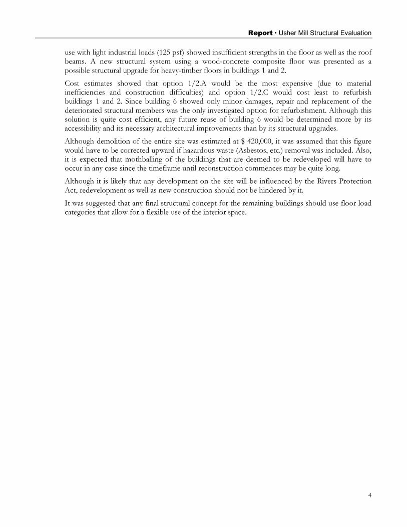
Moisture content readings were only gathered in this building and from columns on the first floor (due to accessibility). Two sets of readings were made: one at approximately 5 ft height and one at 1 ft above the floor covering. All measurements were made using a hand-held resistance-type wood moisture meter.
Results from these measurements indicate a moisture content ranging between 13 and 17% at 5 ft and 20-21% at 1 ft height. While the 5 ft readings are not a cause for concern, the 1 ft readings indicate that all wood at floor level is well within a range where fungal attack is possible.
Figure 15 - Building 2: Deterioration at Roof Drain;
Sagging Molded Beam in SW Corner
Due to the moisture transported through the structure, the interior side of the basement concrete wall is damp (Figure 16). In addition, the outside of this wall showed some vertical cracks at the floor beam locations in the south-eastern corner of the building. Since this area could not be viewed from the inside it is only speculated that the cracks might be due to moisture expansion of the floor beams.
Figure 16 - Building 2: - 1st Floor Decking Deterioration;
Mold on 1st Floor Beams, Moisture in Concrete Basement Wall
Report· Usher Mill Structural Evaluation
25
Masonry in this building appears to be mostly in good condition. On the inside, water intrusion led to cracking of paint in several locations. Although the outside of the wall appears to be in good condition for the entire first story, some mortar joint deterioration and spalling can be observed at the roof level. This is very likely due to water intrusion and freeze-thaw effects.
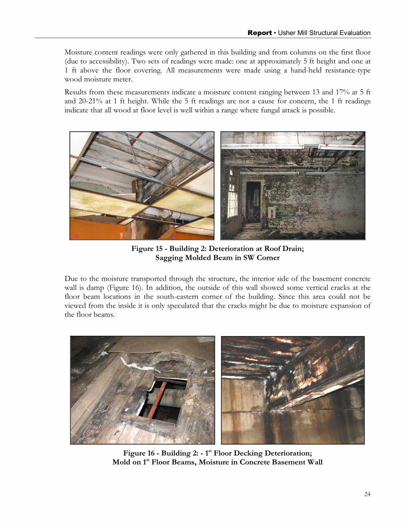
Building 3:
This building – which has no wooden structural members – appears to have had only very little water intrusion (see Figure 17). This may have been due to a larger roof slope (compared to buildings 1 and 2). Any water that has entered the walls is very likely caused by drainage problems of the adjacent roofs (or ponding between roof slopes).
This structure appears to have a built-up roof consisting in part of cementitious plates that enclose the top chord of all steel trusses. While this also may have contributed to the little water intrusion, it can be observed that the entire roof underside shows discoloration which may indicate some deterioration or have been caused by smoke from the original use as a boiler house.
All walls as well as the concrete floor appear to be in a dirty but good condition.
Figure 17 - Building 3: Various Masonry Types; Truss Bearings
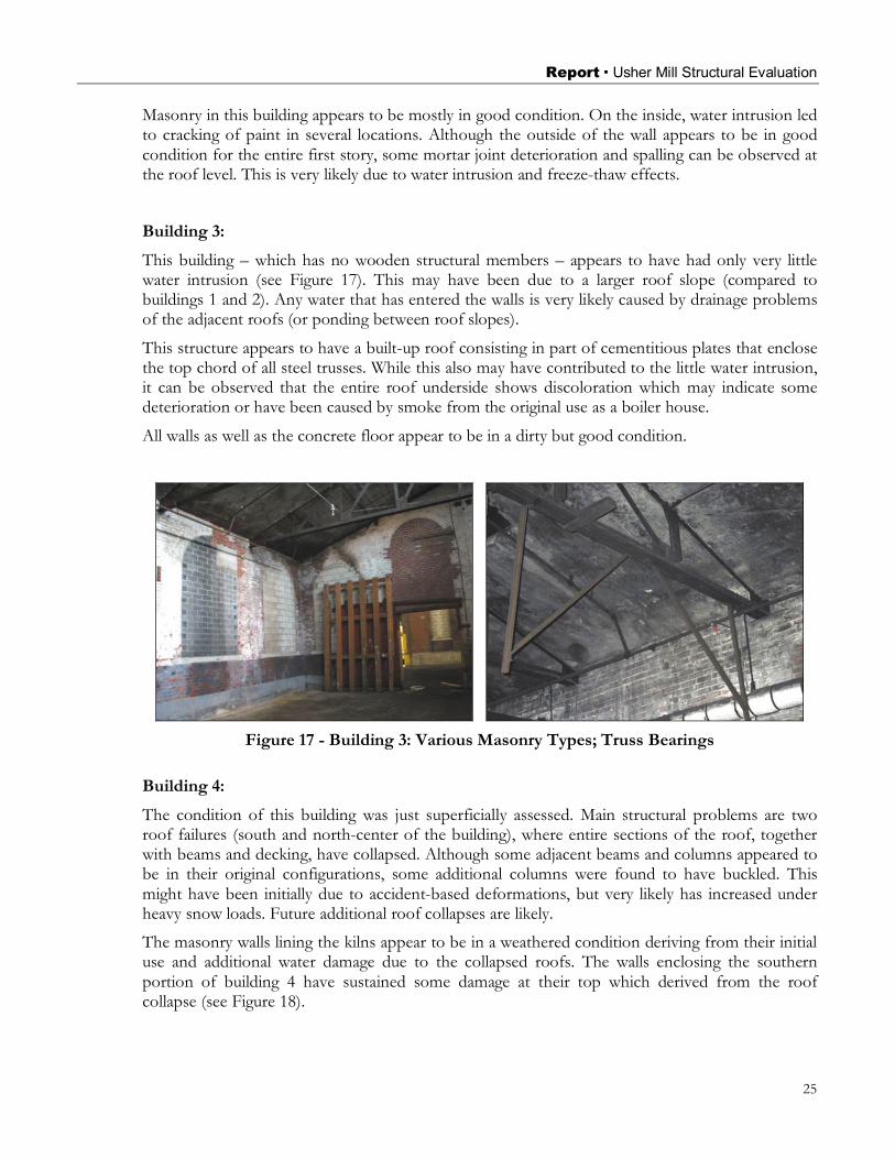
Building 4:
The condition of this building was just superficially assessed. Main structural problems are two roof failures (south and north-center of the building), where entire sections of the roof, together with beams and decking, have collapsed. Although some adjacent beams and columns appeared to be in their original configurations, some additional columns were found to have buckled. This might have been initially due to accident-based deformations, but very likely has increased under heavy snow loads. Future additional roof collapses are likely.
The masonry walls lining the kilns appear to be in a weathered condition deriving from their initial use and additional water damage due to the collapsed roofs. The walls enclosing the southern portion of building 4 have sustained some damage at their top which derived from the roof collapse (see Figure 18).

Report· Usher Mill Structural Evaluation
26
Figure 18 - Building 4: Roof Collapse; Damaged Masonry Wall
Building 5:
This building, which consists of a roof and partial wall enclosure over the atrium between buildings 1, 2 and 3, also shows the effects of water leakage through the roof.
As can be observed at the wall bearings of some of the open-web steel trusses, water intrusion has led to the formation of rust (see Figure 19, right). This in turn led to the deterioration of some trusses at that crucial location which subsequently allowed the failure and collapse of some of these trusses at the eastern end of the building (over the loading dock). It is thus very likely that more roof collapses will occur since other trusses are rusting as well. In addition, deflected trusses near the roof collapse will accumulate snow and are very likely to fail under these conditions.
Figure 19 - Building 5: Partial Roof Collapse; Water Damage
The majority of the corrugated metal ceiling as well as the added walls on the northern and north-western sides of this building appear to be in good condition. The same is true for the concrete floor.

Report· Usher Mill Structural Evaluation
27
Building 6:
Although this is the largest building on the site, it shows a comparably small amount of structural damage. Generally, most floor and roof beams and joists as well as the interior columns appear to be in sound condition. The only problematic areas are located at a number of small roof leakages.
Water entering the buildings at these points led to severe but quite localized damages (as can be seen in Figure 20, right). These damages typically extend to both the roof as well as the floor structure and may also be present in the column.
Figure 20 - Building 6: Intact Floor System (Note: Eccentricity of Column);
Mold Damaged Floor Beams and Joists
Building 7:
This building was not assessed.
Figure 21 - Building 7: Walls and Roof Structure Detail

Report· Usher Mill Structural Evaluation
28
4 Options for Action In preparing the options for action it was assumed that no identifiable uses exist for buildings 4, 5 and 7.
Two roof collapses in building 4 together with a very simple structural system led to the conclusion that there is no remaining value in this building and that it should be demolished. Although building 7 did not experience any major collapses, it was believed that its windowless nature leaves it with very few options for reuse and that it, too, should be demolished.
Building 5 also experienced a partial roof collapse on its eastern end (directly above the loading dock). Rusting of additional structural members may lead to further instability and it is recommended that unless the soundness of the remaining steel trusses is guaranteed, this building should also be demolished. In any case, the existing roof collapse will prevent even load distribution and may create problems also for the adjacent buildings 1 and 2.
Demolition of buildings 5 and 7 would allow for removal of the masonry infill in the adjacent structures’ windows thereby creating additional access to daylight.
4.1 Refurbishment Options The following targeted uses were assumed for the refurbishment of the Usher Mill buildings:
Housing
Commercial / retail / office space
Light industrial use
Mixed use
Mothballing
Demolition
For the purpose of a structural evaluation, these uses can be agglomerated into the following categories:
50 psf Category: Multi-family housing (40 psf), offices (50 psf)
125 psf Category: Retail (100 psf, first floor), light industrial (125 psf)
Demolition (full or partial)
By evaluating and later designing the structures according to these load categories, a provision is made to allow for flexible uses of the refurbished space. As an example, if the structures were designed for 50 psf and developed into offices, the option would exist to later re-position interior partition walls and create residential space – if this was needed.
Due to the interior layout of the buildings on the site, it does not appear feasible to consider the 50 psf category for buildings 3 or 6 whose floor layout is not at all conducive to housing or office uses.

Report· Usher Mill Structural Evaluation
29
4.1.1 Buildings 1 and 2 The following refurbishment options provide open interior spaces similar to the existing layout. This allows for a flexible arrangement of partition walls. In addition, all existing outside masonry and concrete walls are retained (for historic value, aesthetics and Rivers Protection Act compliance, if needed).
All options include removal of interior partitions (light-frame walls, dropped ceilings, etc.) and deteriorated floor coverings. Limited masonry refurbishment (mostly near eaves) and concrete perimeter wall repair have also been added.
Additional construction will be required for lateral load-resisting elements such as shear walls or diaphragms and/or improvements of foundations. This, however, has not been included in these options.
Option 1/2.A: Keep Timber Structure / Replace Damaged Beams and Decking
Figure 22 - Refurbishment Option 1/2.A
Involves:
Remove roofing, floor and roof decking (to examine all beams)
Replace severely damaged members with glulam or solid sawn members, remove damaged material from lightly damaged members
Re-saw removed beams into decking
Replace decking (incl. recycled material)
Issues:
Keeps original structure and structural members to a high degree. Preserves historic value, if desired
Uncertainty of extent of damages until all decking and interior partitions are removed (possible additional costs)

Report· Usher Mill Structural Evaluation
30
First floor columns need to be supported (shored) while beams below are being replaced
Possible option of reinforcing of floor plates with wood-concrete system
Option 1/2.B: Replace Timber Structure with Glulam Post-and-Beam
Figure 23 - Refurbishment Option 1/2.B
Involves:
Remove roofing, floor and roof decking
Remove entire timber structure (recycle and/or sell)
Re-saw beams into decking
Erect new glulam frame (same layout)
Replace decking (incl. recycled material)
Issues:
Keeps the “feel” of the original structure while providing a modern replacement. Preserves historic idea
Walls may need to be stabilized during construction
Good cost certainty
Option of reinforcing of floor plates with wood-concrete system

Report· Usher Mill Structural Evaluation
31
Option 1/2.C: Replace Timber Structure with Light-Frame Structure
Figure 24 - Refurbishment Option 1/2.C
Involves:
Remove roofing, floor and roof decking
Remove timber structure, recycle beams and decking
Erect new light frame structure (stud or Laminated Strand Lumber (LSL) walls, glulam or Parallel Strand Lumber (PSL) posts and headers, open-web joists, plywood sub-floors)
Issues:
Upgrades interior of structure and may improve energy efficiency while keeping the exterior consistent with historic structure
Walls may need to be stabilized during construction
Good cost certainty
Open-web trusses allow for services (ductwork etc.) within floor height
Double wall reduces structural dependency on old masonry and offers added insulation space
Option 1/2.D: Demolish Buildings
Involves:
Removal of structure including all foundation piers and walls
Issues:

Report· Usher Mill Structural Evaluation
32
This may be done partially. E.g.: only building 1 or building 2 or one half of building 2 can be demolished.
4.1.2 Building 3 Although this building has not been assessed structurally, one option for refurbishment will be discussed here. If this building is to be retained, a thorough investigation of the condition of the roof and its supporting steel trusses should be undertaken. At this point, it is assumed that both only need minor repairs.
Option 3.A: Keep Structure / Repair Minor Damages
Involves:
Remove boilers
Clean and repair masonry and concrete (if needed)
Issues:
Roof, steel trusses, masonry and smokestack need to be investigated for any damages that would require their replacement or removal
Due to the previous use as a boiler room, asbestos removal will be necessary
Option 3.B: Demolish Structure
Involves:
Removal of structure including boiler, smokestack, foundations and walls
Issues:
Asbestos removal will be necessary
4.1.3 Building 6 Since this structure is in an acceptable condition, only one re-use option has been evaluated. This option simply replaces damaged structural parts.
It should be noted that due to the utility nature of this building, any change from the use as a warehouse may need extensive architectural work which would include creating a thermally viable building enclosure, the addition of services and utilities and the upgrading of some structural elements. Since this can significantly add to the cost, future re-use may be limited by these costs rather than the structural remediation presented below.
As with buildings 1/2, additional construction may be required for lateral load-resisting elements such as shear walls or diaphragms and/or improvements of foundations. This, however, has not been included in these options.
Option 6.A: Keep Structure / Replace Damaged Members

Report· Usher Mill Structural Evaluation
33
Involves:
Replace severely damaged beams and joists with glulam, solid sawn or dimension lumber, remove damaged material from lightly damaged members
Repair floor and roof decking
Issues:
First floor may need to be supported while beams below are being replaced
Option 6.B: Demolish Structure
Involves:
Removal of structure including all foundation piers and walls
4.1.4 Mothballing Due to the expected timeframe for the development and implementation of any of the refurbishment options, mothballing will be necessary at some point. To reduce the amount of work and maximize the protection of the buildings and structural parts that are slated for re-use, mothballing should follow these goals:
Determine which structures are to be retained and protect these from demolition or deconstruction efforts in adjacent buildings.
Protect these structures from accidental collapse due to deteriorating members (where failure would have a trigger effect) and/or collapses in adjacent buildings.
Protect all interior structural members from further exposure to water and allow the wooden structural members to dry out.
These goals require the following actions:
Structural temporary support needs to be installed for highly deteriorated members (the effect of this support on the structure below has to be accounted for). This applies mainly to buildings 1 and 2 wooden beams, headers and rafters.
Structural members in danger of collapse that are located adjacent to a building that is to be protected should be either sufficiently supported or removed. This applies mainly to buildings 4 and 5.
A tight building enclosure has to be created by boarding up windows, fixing roof leaks and opening roof drains. Note: a protected path of cross-circulating air should be created in the buildings so that existing moisture can evaporate and be transported to the outside. Heating or mechanical ventilation are beneficial but might not be needed if sufficient time is available for the drying process. Regular inspection of the soundness of the enclosure is also suggested. While this applies to all buildings that are to be retained, main focus should be laid on buildings 1, 2, 3 and 6.

Report· Usher Mill Structural Evaluation
34
4.2 Problems due to Fungal Infestation Molds and other fungal infestations of structures are a problem for potential redevelopment in many ways. Primarily, they pose a health hazard for occupants if they are not properly removed. Also, contractors involved in the renovation of the building are exposed to any spores that may become airborne. In addition to that and depending on the type of fungus they can affect and destroy structural wooden members. It is thus important that all structural and non-structural members which are heavily affected by fungal growth are thoroughly cleaned or removed, if necessary.
Fungal infestation needs a set of criteria to establish itself in a building. Since fungal spores exist in the air or live dormant in organic materials or on inorganic surfaces, it is impossible to prevent the arrival of these spores. By themselves, fungal spores pose no danger in any case. In order for molds or rot to grow, three additional ingredients need to be present: One is a sustained supply of water, another is air and the third and most important one is the availability of a food source. Since this food source needs to be of an organic nature, wood beams that have been sufficiently moistened (above approx. 20% moisture content) are prime targets for any attack.
In order to remove any fungal problems in wood structures, the most important action that is needed is always the removal of the “water supply”. Once an infected wood-based building product is allowed to dry out, fungal growth stops and thereby arrests any decay that might be occurring. At that point, the decision has to be made whether a structural member is decayed too far and needs to be replaced or whether it can be treated by simply removing a safe area around a decayed zone.
In any case, it can be a costly undertaking to treat any wooden structure that contains mold. This is especially true for structures whose mold problem is of a significant size as can be found in the Usher Mill. The following issues are therefore pertinent for this project:
Several types of wood affecting fungi exist. Among them are stains that simply discolor the member, molds that grow on and possibly in the wood and rot, which breaks down the cell structure of the wood leaving it useless for any purpose. Although it is possible to identify the exact type of damage that is present in a wooden member, the size of the Usher Mill complex renders it cost prohibitive to do so. Unless there is a clear historic or architectural value to the specific wooden member and the higher cost is justified, it would be more feasible to remove damaged beams and replace them with new ones. Another option would be to simply replace the entire wooden structural system.
Since all structural beams, headers and rafters are covered with decking, it is not possible to assess the full extent of the damages before it has been removed. This introduces a vague variable into the cost calculation.
In the absence of an identification of the exact kind of deterioration for each structural member, structural engineers will not likely assume the responsibility for re-using even partially damaged wood.
If selective replacements of water damaged structural members are desired, then work-safety requirements for contractors will likely increase the cost for renovation.

Report· Usher Mill Structural Evaluation
35
4.3 Preliminary Structural Analysis A preliminary structural analysis and re-design of the wooden members was performed for buildings 1, 2 and 6. In this analysis, only vertical loads were considered (i.e. snow, live, dead). Lateral loads were ignored since these would have to be accommodated either by the existing masonry walls or by additional structural elements (shear walls, floor diaphragms etc.) which typically also serve an architectural function. In both cases, construction costs are very dependent on the chosen structural system and may vary in a wide range. Also, the effect of the vertical (and horizontal) loads on the foundations was ignored since no geotechnical information was available and the size of the foundations could not be determined. All foundations were assumed to be able to take the applied loads. In a final structural analysis (by a registered professional engineer) these load paths will be included.
The analysis and re-evaluation of the beams, columns and the decking was done using the measured actual dimensions (not nominal sizes). Also, it was initially assumed that all members are in a sound condition. This allowed for the determination of the structural capacity of the existing structure and provided required strengths and dimensions for any replacement members.
Since the in situ strength of the material (Southern Yellow Pine) was not known, assumptions had to be made regarding the applicable allowable stress values. All structural members were thus initially assigned the lowest tabulated strength values (Southern Pine, visually graded timbers, No. 2 grade, 5 in x 5 in and larger) in the currently applicable code (AF&PA, 1997). This practice usually provides a conservative estimate of the strength since it is very likely that a) high quality material was used since old-growth timbers with higher material strengths were available at the time of construction and b) tabulated values are based on “wet” timbers, which is not representative of the dry state that the sound wooden members are in.
The analysis and the re-design of the wooden members followed guidelines laid out in the current standard for timber structures, the “National Design Specification for Wood Construction” (AF&PA, 1997).
4.3.1 Buildings 1 and 2 An analysis of these buildings (which feature structurally equivalent systems) showed that the typical office floor loads (50 psf + 20 psf for partitions) as well as the applicable roof loads (35 psf) can be taken by the existing structure (if it were intact). All structural members (except one type – the roof headers) would be stressed less than their allowable values (or are underdesigned by less than 10%). With the given assumptions, however, the roof header beams are underdesigned by 45%.
This problem could be remediated by a closer inspection and a visual (or mechanical) grading of the roof header beams. Results from this process could permit the classification of these beams as No. 1 material in which case they would also pass the design check.
An analysis of the same structure with light industry loads (125 psf) acting on the floors and the same roof loads as before yields a less favorable outcome for the first and second floor beams and columns.
Since the roof loads do not change for this scenario, the roof headers are also underdesigned in this case. In addition, given the higher floor loads, all first and second floor beams, headers and the
Report· Usher Mill Structural Evaluation
36
first floor columns fail the design check by approximately 40-50%. Similar to before, those members would also pass if their grading could be upgraded to No. 1. If this were not possible, then the affected members would have to be reinforced or replaced by stronger material.
It was found that the decking material passes the design check under either load (offices and light industrial).
Both analyses assumed a light floor covering (which is currently in place). If this were upgraded to a heavier covering (e.g. concrete topping) or if large point loads were introduced, the capacity of all members would have to be re-evaluated.
If structural members were to be replaced as in option 1/2.A, a height limit is imposed on any replacement. Since most existing beams do not have an optimized cross-section (narrow and tall would usually have been better than stocky or almost square shapes), the replacement might have to use more material than would be necessary. In contrast, if the entire structure would be replaced (as in option 1/2.B), the relatively large story heights would allow for the use of more optimized beams and headers which in turn would save on material and costs.
When considering a refurbishment option, it is also important to consider code issues. As an example, the Massachusetts Building Code (170 CMR, 1997) imposes minimum cross-sectional dimensions on all exposed members in a heavy-timber structure. Therefore, columns cannot be installed with any dimension measuring less than 8 in nominal and beams need to measure at least 6 in in width and 10 in in height (joists ≥ 3 in width). Since these dimensions are mainly imposed due to fire regulations, an added fire protection (treatment, gypsum boards etc.) may allow smaller sizes to be used. This, however, may change the appearance of the structure.
Additionally, the Massachusetts Building Code requires “stress-grade timbers” to be used for heavy-timber construction. While this is not a problem for the glulam members required in option 1/2.B (since they are manufactured industrially), the replacement of solid-sawn members required in option 1/2.A might require additional, costly stress-grading to be performed.
4.3.2 Building 6 Consistent with the intentions for this structural analysis, building 6 was only evaluated for light industrial floor loads (125 psf).
Results from this analysis showed that the roof joists, first floor joists and first floor columns pass the design check (for structurally sound material). In contrast, the roof as well as the first floor beams fail by 10-40%.
As before, it is suggested that the roof and floor beams are inspected for possible classification as No. 1 grade material. If this process was successful, all beams would pass the bending design check. While shear is not a problem in the roof beams, the floor beams would still fail the shear design check by a margin of 10% even after an upgrade to No. 1. This would be acceptable only if little splitting was observed in the beams since this might allow a higher shear stress factor (CH) and thus permit a higher strength.
The roof and floor diagonal beams as well as the additional wooden foundation piers have not been considered in this analysis.
Report· Usher Mill Structural Evaluation
37
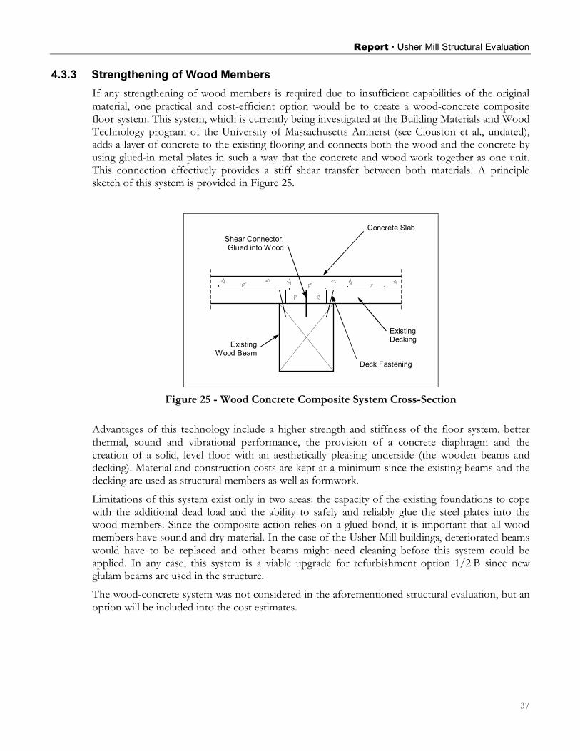
4.3.3 Strengthening of Wood Members If any strengthening of wood members is required due to insufficient capabilities of the original material, one practical and cost-efficient option would be to create a wood-concrete composite floor system. This system, which is currently being investigated at the Building Materials and Wood Technology program of the University of Massachusetts Amherst (see Clouston et al., undated), adds a layer of concrete to the existing flooring and connects both the wood and the concrete by using glued-in metal plates in such a way that the concrete and wood work together as one unit. This connection effectively provides a stiff shear transfer between both materials. A principle sketch of this system is provided in Figure 25.
Concrete Slab
Existing Decking
ExistingWood Beam
Shear Connector,Glued into Wood
Deck Fastening
Figure 25 - Wood Concrete Composite System Cross-Section
Advantages of this technology include a higher strength and stiffness of the floor system, better thermal, sound and vibrational performance, the provision of a concrete diaphragm and the creation of a solid, level floor with an aesthetically pleasing underside (the wooden beams and decking). Material and construction costs are kept at a minimum since the existing beams and the decking are used as structural members as well as formwork.
Limitations of this system exist only in two areas: the capacity of the existing foundations to cope with the additional dead load and the ability to safely and reliably glue the steel plates into the wood members. Since the composite action relies on a glued bond, it is important that all wood members have sound and dry material. In the case of the Usher Mill buildings, deteriorated beams would have to be replaced and other beams might need cleaning before this system could be applied. In any case, this system is a viable upgrade for refurbishment option 1/2.B since new glulam beams are used in the structure.
The wood-concrete system was not considered in the aforementioned structural evaluation, but an option will be included into the cost estimates.

Report· Usher Mill Structural Evaluation
38
5 Cost Estimation Costs were estimated for the refurbishment and demolition options presented in the previous chapter. This was done using a variety of sources ranging from general-purpose estimating handbooks to preliminary budgets supplied by contractors and manufacturers. See Appendix C for details.
Table 2 presents an overview of the costs related to the various reconstruction and demolition options.
Building(s) Option A Option B Option C Deconstruction Demolition
# 1 386,000 353,000 332,000 325,000 53,000
# 2 776,000 660,000 617,000 594,000 105,000
# 3 38,000 --- --- 198,000 41,000
# 6 50,000 --- --- 152,000 120,000
# 4, 5, 7 --- --- --- --- 100,000
Sum: 419,000
Table 2 - Refurbishment Cost Estimates (per Building)
Two further (separate) optional upgrades were estimated for buildings 1 and 2 as well: A wood-concrete structural upgrade for options 1/2.A and B and a light-weight concrete floor topping for option 1/2.C. If these were considered, the wood-concrete option would add $ 50,000 and $ 99,000 to buildings 1 and 2, respectively and the light-weight concrete topping would add $ 30,000 and $ 59,000 to these. Because the light-weight concrete topping increases the load on the structural members, cost increases in the refurbishment option (1/2.C) for the main structure are likely whereas the wood-concrete composite system for option 1/2.B could reduce the overall amount of wood needed thereby making it a cost-efficient upgrade.
Cost figures for options A, B and C (as presented in Table 2) include only structural refurbishment works (less an allowance for timber resale). The following items have thus been excluded:
Hazardous materials (e.g. Asbestos) removal – This item may significantly increase both the refurbishment and demolition costs (depending on the degree of contamination)
Foundation improvements – In developing the structural analysis and the cost estimates, it was assumed that all foundations (point foundations under columns and strip foundations under walls) are capable of taking all loads. This must be verified by a geotechnical analysis and a structural analysis considering the actual size and type of the existing foundations has to be produced
Roof replacement
Roof additions (e.g. skylights) – Since no access to the roof was gained, all roof features have been excluded

Report· Usher Mill Structural Evaluation
39
New staircases and elevators – These were considered to be architectural features
Utilities and services
Building additions (for architectural detail or usability – e.g. masonry additions or decks)
Architectural features (partitions, doors, windows, finishes etc.)
All insulation
Also, the figures presented in Table 2 are only preliminary since inevitable uncertainties related to the following issues can (possibly severely) influence the totals:
Fluctuations in material and labor costs due to local availability or the overall economic situation
Added overhead since the work is done in existing historical buildings
Skill and quality level of the contractor(s)
Construction process variations, including increased shoring and bracing requirements
Discovery of additional structural deficiencies during the construction process
Architecture and engineering fees
Two sets of figures have been presented for the demolition of the structure. One, termed “Demolition”, refers to the bulk demolition of the respective building using heavy machinery. This typically yields material that – if possible – can only be recycled in a crude fashion (i.e. steel recycling for melting).
The other set of numbers (“Deconstruction”) includes procedures that selectively demolish structural parts. This allows for the removal of these parts in their entirety, permitting a high-value re-use and/or a selective refurbishment process.
All refurbishment and cost estimates have to ultimately be viewed in the context of the actually selected structural systems and construction processes. This may lead to cost-savings or -additions, depending on the combination of systems and processes chosen. Also, demolition costs may be offset to a large degree by the (bulk or piecewise) sale of building materials.
In compiling these estimates, it was found that it was not feasible to separate refurbishment estimates into the structural categories that were presented in the previous chapter (50 psf and 125 psf). The number of assumptions made in the provision of cost estimates did not yield significantly enough detail for the inclusion of every replacement member’s exact dimension into the analysis.
5.1 Refurbishment Buildings 1 and 2:
The analysis of refurbishment options shows that it will be quite expensive to refurbish buildings 1 and 2 if a large part of the existing structure is to be retained. This is mainly due to the currently high degree of deterioration of the wood members in the buildings. Since option A involves selective demolition and replacement of structural members, it is imperative that a high amount of temporary shoring (to support the sound parts of the structure) will be necessary during this process. As this involves a large labour component and possibly cannot be done using heavy
Report· Usher Mill Structural Evaluation
40
machinery (due to lack of accessibility), additional costs are likely. Furthermore, the partial nature of this work may hamper subsequent trades from operating in the building in a timely and cost efficient manner. Due to the highest associated costs, this type of refurbishment is typically only justified by a historic value of the existing structure. Since these buildings are not classified as historic structures and there may not be a will to preserve the interior appearance, the higher costs may not justify this option.
If the entire interior structure is to be removed, as envisioned in option B, reconstruction of the interior structural system is facilitated. While the removed wooden structural members can be sold at a reasonable price, a new structure (albeit based on the original structural system due to existing foundations) can be designed and installed. It would then be possible to take advantage of current, high-performance building materials (glulam, Parallel Strand Lumber etc.) and to take advantage of lower costs due to a more efficient and thus reduced material use. In addition, some costs can be recovered by re-sawing and re-using portions of the old structure – for example as flooring.
A similar approach is taken by option C, which also removes the entire wooden interior structure. In this option, everything that existed between the masonry walls is replaced with a light wooden system using open-web wood/steel trusses in combination with Parallel Strand Lumber headers and columns as well as traditional stud wall systems (2x6) or more dimensionally stable Laminated Strand Lumber walls. Effectively, this system creates a building within a building.
This approach includes some benefits. Primarily, a very light structure is created that may not require any foundation modifications. Also, long trusses can be used for the roof, spanning the entire width of the building thereby allowing for a very spacious upper floor and reducing the loads on the interior foundations. In addition, building utilities can be installed within the truss openings of the floors.
Whichever option is chosen, care has to be taken in combining new and existing (masonry) structural systems. To reduce shrinkage, dry wood or wood-products (which are inherently produced dry) should be used.
In comparison with the other two options, option C provides the lowest-costing structural solution for buildings 1 and 2 – with a higher cost benefit for building 2.
If a wood concrete upgrade were to be specified for buildings 1 and 2, then this would add to the overall costs. Since this system is designed to reduce the amount of wood that is used and replaces a part of it by concrete, cost savings on the wood part are possible. In any case, use of this system would also require a redesign of all structural members.
Building 3:
The investments necessary for refurbishing building 3 primarily revolve around removing the boiler system from the western portion of the building, fixing minor roof leaks (or possibly upgrading the entire roof) and cleaning the walls. If no or only minor hazardous material remediation was necessary for this building, the costs for structural refurbishment would be the lowest among all buildings on the site. However, since this is not very likely, additional costs due to Asbestos remediation can be expected.
Report· Usher Mill Structural Evaluation
41
Building 6:
Due to only minor structural damages, refurbishment costs are very low for building 6. Also, since the damages are localized, repair is possible. Nevertheless, it is assumed in the estimate that the roof only needs to be repaired or replaced in part. As this building’s roof area is very large, a full replacement of the roof will add further costs if this should be necessary. As mentioned before, the major cost component for this building will come from architectural upgrades if it is intended to be used as anything other than a warehouse.
5.2 Demolition / Deconstruction and Mothballing As shown in Table 2, a full demolition of the entire Usher Mill site will cost at least $ 420,000. Since this figure allows for some material recovery and in turn ignores dump fees, the actual cost will very likely be dependent on the quality of the remaining reusable building materials and the type of demolition chosen.
The numbers presented under deconstruction reflect a process that selectively demolishes the buildings. While this does not reflect the demolition costs for entire buildings as a whole, it is meant as a source for an estimation of partial demolition costs assuming that this is needed during the planning process.
The major cost factor associated with mothballing is the selective demolition of adjacent structures in danger of collapse (buildings 4 and 5). Further work related to boarding up windows and sealing the roofs adds only minimally to the cost since only temporary fixes using low-quality materials are employed.

Report· Usher Mill Structural Evaluation
42
6 Conclusions and Recommendations The following points summarize the findings of this study:
The buildings on the Usher Mill site consist of typical industrial structures from the beginning of the 20th century as well as lesser quality buildings dating from the middle of that century. Architecturally, the most interesting structures are buildings 1, 2 and 3.
Although any development on the site will likely be influenced by the Rivers Protection Act, redevelopment as well as new construction should not be hindered by it.
The sole cause for the current state of structural deterioration of most of the buildings was the negligence to maintain a sound enclosure after the buildings had been vacated. Roof leaks as well as vandalized windows allowed the uncontrolled intrusion of water into the structures and caused structural deterioration of the wooden members in buildings 1, 2 and to a lesser extent 6. This deterioration is more widespread in the lower floors than it is on the roof.
Buildings 1 and 2 have structurally deficient beams, rafters and headers totaling at least 40-50% of all members. Columns are affected to a lesser degree, but moisture levels are high enough that undiscovered deterioration at their bases is very likely. Building 6 only had minor roof leaks and therefore its structural damages are few and localized. Masonry and concrete structural elements are generally in good condition. Only the outside walls of buildings 1 and 2 have suffered mortar joint deterioration and spalling near the eaves and concrete foundation perimeter walls are showing vertical cracks in some locations which need to be repaired. Steel members in building 3 appear to be in good condition but some open-web roof trusses in building 5 have collapsed due to water intrusion and rusting.
Due to its previous use as a boiler house, building 3 likely has Asbestos in its ceilings and pipe insulation, which needs to be removed. The extent of the hazardous materials in all buildings needs to be evaluated before any final renovation cost estimate can be produced.
Existing structural collapses and overall architectural layout suggest that buildings 4, 5 and 7 should be demolished.
A final structural concept for the remaining buildings should use floor load categories that allow for a flexible use of the interior space.
Three refurbishment options were presented for buildings 1 and 2. These consisted of either retaining the current structure and replacing its deteriorated parts (option 1/2.A) or removing the entire interior wooden structure and replacing it with a heavy-timber (option 1/2.B) or a light frame structure (option 1/2.C). Option 1/2.C effectively involved the creation of a separate building within the existing walls.
A structural analysis of buildings 1 and 2 showed that although the existing structure (if sound) would be able to carry loads (with minor limitations) from the 50 psf category that includes offices and residential uses, industrial or retail loads would not receive sufficient support unless the existing structure is either upgraded or its material is re-evaluated. The analysis of building 6 for re-use with light industrial loads (125 psf) showed insufficient strengths in the floor as well as the roof beams.
Cost estimates showed that option 1/2.A would be the most expensive (due to material inefficiencies and construction difficulties) and option 1/2.C would cost least to refurbish
Report· Usher Mill Structural Evaluation
43
buildings 1 and 2. Since building 6 showed only minor damages, repair and replacement of the damaged structural members was the only investigated option for refurbishment. Although this solution is quite cost efficient, any future reuse of building 6 will be determined more by its accessibility and its necessary architectural improvements than by its structural upgrades.
A new structural system using a wood-concrete composite floor was presented as a possible structural upgrade for heavy-timber floors in buildings 1 and 2.
Building 3, which is also not usable as office or residential space, appears to be in good condition. Nevertheless, Asbestos removal will increase the cost of any refurbishment that otherwise would only include roof fixes and masonry cleaning (in addition to a removal of the boilers).
Although demolition of the entire site was estimated at $ 420,000, this figure will have to be corrected upward if hazardous waste (Asbestos, etc.) removal is included.
Mothballing of the buildings that are deemed to be redeveloped will have to occur in any case since the timeframe until reconstruction commences may be quite long.
Future work towards a redevelopment of the Usher Mill site will primarily require an architectural consultant who will take suggestions from this and other related reports to create detailed and complete options for the re-use of the buildings (or the space). This will include a final structural form, a building layout related to the intended use(s) and a complete estimation of all involved costs. From the structural perspective, a registered professional engineer contracted with the design of the final structural system will need further information about the soil makeup under the site and the state of the existing foundations. These issues will have to be addressed by a geotechnical study, which is typically commissioned during the early structural design stage.
Any development options for this site may be affected by the findings of an environmental assessment of the grounds surrounding the buildings (currently underway) as well as a hazardous materials survey of the structures. Only then can final construction costs be estimated with a high degree of certainty.
Finally, the success of any commercial/retail development may depend on an improvement to the current site access (i.e. the railroad underpass). The one-lane underpass may be a psychological barrier between the busy Route 2 and a commercial venture located in the re-developed mill on the other side of the tracks. Also, some rescue vehicles may not be able to use the underpass in its current size (as stated by the town government). Since this is a safety issue, it will have to be addressed early in the re-development process.
In spite of the challenges that stand between the site in its current and future state, a creative development solution combined with the strong will of the residents of Erving may provide new life for a depressed and underused site that benefits from a central location and a wide range of possible uses. It is desirable in any case – with respect to environmental, social and economical aspects – that towns and cities close open gaps in their cores before they venture out onto the open fields. This limits resource use by providing a more efficient agglomeration of needs.
The Usher Mill site, which also contains a key element of Erving’s history, provides an opportunity to develop a central portion of a typical New England mill town and create a foundation for future economic and social prosperity.

Report· Usher Mill Structural Evaluation
44
Consistent with the assumptions and findings of this report, the following figure (Figure 26) shows a possible (re-)development solution for the site.
Figure 26 - (Re-)Development Option (X = Demolished Structures)
6.1 Required Immediate Actions If a decision is made to retain at least some of the buildings on the Usher Mill site, the following steps should be taken immediately to protect them until construction can commence:
Structural members in danger of collapse (or already partially collapsed) need to be temporarily supported or removed to prevent further catastrophic collapses and allow for maintenance or construction work to be performed safely.
Leaking roofs need to be at least temporarily fixed to hamper any further water intrusion. Where drains and downspouts are incapable of performing properly, alternatives must be provided.
Windows should be boarded up so that rain or snow cannot enter the buildings and deteriorate the structures further. When this is done, a “ventilation path” through the buildings needs to be created that allows moisture from drying structural members to leave the building. This may be assisted by the installation of heat or mechanical ventilation to draw air from the buildings.
These recommendations should be implemented before the next winter so that the structures are protected from additional collapses due to snow loads and/or further water intrusion.
With respect to future development, one of the first issues to be resolved is very likely the question of hazardous materials in these buildings. It is thus suggested that detailed estimates be gathered from several companies specializing in the removal of these materials. This process should provide the town with reliable estimates of expected costs.
X X
X
New X

Report· Usher Mill Structural Evaluation
45
References and Further Reading Usher Mill / Massachusetts Mills:
Hoke A., Nunes, R., Williamson, T. 2000. “Usher Plant Revitalization Plan – Erving, Massachusetts”. Report. University of Massachusetts, Amherst, MA
Mass MoCA. 2000. “Mass MoCA – From Mill to Museum”, Ed. Trainer, J. Mass MoCA Publications, North Adams, Massachusetts
Mattos, M.J. 2002. “The Usher Plant Review and 8-Point Action Plan”. Report. University of Massachusetts, Amherst, MA
Wetlands / Rivers Protection Act:
Massachusetts General Laws, Chapter 131, § 40. “The Wetlands Protection Act”. Commonwealth of Massachusetts, Boston, MA
310 CMR 10.00 – 1996. “The Wetlands Protection Act Regulations”. Commonwealth of Massachusetts, Boston, MA. Available at: http://www.state.ma.us/dep/brp/ww/files/310cmr10.pdf
Scott D. Jackson, Extension Specialist, Department of Natural Resources Conservation, University of Massachusetts, [email protected], 1 (413) 545-4743
Structural Design:
170 CMR – 1997. “Massachusetts State Building Code”. Commonwealth of Massachusetts, Boston, MA
AF&PA (American Forest and Paper Association) 1997. “National Design Specification (NDS) for Wood Construction”. Washington, DC
Clouston, P., Civjan, S., Bathon, L.A. (accepted for publication). “Experimental Behaviour of a Continuous Metal connector for a Wood Concrete Composite System”. Forest Products Journal, Madison, WI
Rabun, J.S. 2000. “Structural Analysis of Historical Buildings”. J. Wiley & Sons, New York
Mold in Buildings:
Canadian Mortgage and Housing Corporation. “Moisture and Mold”. Available at: http://www.cmhc-schl.gc.ca/en/burema/gesein/Momo/index.cfm
Forintek 2002. “Discolorations on Wood Products – Causes and Implications”. Forintek Canada Corp., Vancouver, BC. Available at: http://www.durable-wood.com/pdfs/discolor_eng.1oct02.pdf
Garrett, D. 2003. “Indoor Mold – Causes & Cures”. Journal of Light Construction, June 2003, pp. 65-71

Report· Usher Mill Structural Evaluation
46
New York City Department of Health & Mental Hygiene. “Guidelines on Assessment and Remediation of Fungi in Indoor Environments”. Available at: http://www.nyc.gov/html/doh/html/epi/moldrpt1.html
Costs:
RSMeans 2003. “Repair & Remodeling Cost Data, 2003 Book, 24th Edition”, RSMeans, Kingston, MA

Report· Usher Mill Structural Evaluation
Appendix A – Plans of Usher Mill Site and Buildings

Report· Usher Mill Structural Evaluation
Appendix B – Plans of Condition of Structural Members

Report· Usher Mill Structural Evaluation
Appendix C – Estimating Data