preliminary subsurface exploration...7.1 description of soils (visual-manual procedure) (astm d...
TRANSCRIPT

PRELIMINARY SUBSURFACE EXPLORATION
AND GEOTECHNICAL ENGINEERING
EVALUATION
BECK'S TURF FARM 5 (SITE #3) 296-ACRE TRACT - TUSKEGEE, ALABAMA
BUILDING & EARTH PROJECT NUMBER:
C011277
PREPARED FOR:
MACON COUNTY ECONOMIC DEVELOPMENT
AUTHORITY
PREPARED BY:
Geotechnical, Environmental , and Materials Engineers
DATE:
NOVEMBER 10,2011

Geotechnical. Environmental and M:uerials Engineers
5045 Milgen Court, Unit #2 • Columbus, GA 3 1907 • Ph: (706) 562-0048 • Fax: (706) 565-6733 www.BuildingAndEarth.com
November 10, 2011
Macon County Economic Development Authority 608 Dibble Street, Suite 7 Tuskegee, Alabama 36083
Attention: Mr. Joe Turnham
RE: Preliminary Subsurface Investigation Beck's Turf Farm 5 (Site #3) - 296 Acre Tract Tuskegee, Alabama Building and Earth Project No.: CO 11277
Dear Mr. Turnham:
Building & Earth Sciences, Inc. has completed the authorized preliminary subsurface exploration and geotechnical engineering evaluation for the approximate 296 acre tract of land known as Beck's Turf Farm 5 (Site #3) in Tuskegee, Alabama.
The purpose of our exploration and evaluation was to determine general subsurface conditions and to gather data on which to base a preliminary geotechnical evaluation. The recommendations in this report are based on observation and classification of samples obtained from soil test borings drilled at thirteen (13) locations across the approximate 296 acre site. Confirmation of the anticipated subsurface conditions during construction is an essential part of geotechnical services.
We appreciate the opportunity to provide consultation services for this project. If you have any questions regarding the information in this report or need any additional information, please call us.
Sincerely, BUILDING & EARTH SCIENCES, INC.
~t::.~t-u Project Manager
'''"""'''' ''''\,P..BAM..q ,,,, ~ ... ········· ,,
1' .••(:,E.NS£6••. ', ·v- . •• ,
' - 3~~~ Reza Savabi, P.E. : '* \PROFESSIONAL: :
Project Engineer "; •••• 1/ --1 L~;/ ~ § ~ ., •• ~NGlN~~· ~ '
41',.-"f9o··.......... ~ "{ ,,' ,,,, Ot R. S\,,'
''''"""''' Birmingham, AL • Auburn,AL • Columbus, GA • Huntsville, AL • Louisville, KY
New O r leans, LA • Raleigh, NC • Savannah, GA • Shreveport, LA • Springdale, AR • Tulsa, OK
TABLE OF CONTENTS 1.0 EXECUTIVE SUMMARY ............................ ......... ....... .... .... .... ... .. ..... .... ..... .. ...... 1
2.0 PROJECT DESCRIPTION ....... ....... .... .. .... ... ..... ..... ...... .... ... ..... .... ....... ...... ... ..... . 2
3.0 SCOPE OF SERVICES .. ... ......................... .... ... ...... ... ..... ........ .. ..... ... .. ..... .... .... . 2
4.0 SITE DESCRIPTION ... .. .... ........... .... ..... .. .......... ....... .... .. ........... ......... ... ... .......... 2
5.0 AREA GEOLOGY ......... ...... ........... .... ... .. ............................................... ............ 3
6.0 SUBSURFACE EXPLORATION ....... ............ ...... ........................................... .... . 3
6. 1 SOIL TEST BORINGS ..... .... ....... ... ... ... ............. ................ .... .... ............. ...... 3
7.0 LABORATORY ANALYSIS ..... .. ............... .......... ..... .. ....... .... ... ...... .. ..... .. ..... ....... . 4
7.1 DESCRIPTION OF SOILS (VISUAL-MANUAL PROCEDURE) (ASTM D 2488) 4
7.2 WASH #200 TEST (ASTM D 422) ... .... .. ..... ...... .. ...... .. ...... ....... ...... .... ... .... .... 5
7.3 NATURAL MOISTURE CONTENT (ASTM D 2216) ............ .. ..... ...... ... .... ... ..... 5
7.4 ATTERBERG LIMITS (ASTM D 43 18) ...... .... ..... ... ..... .... .... ...... ... ........... ... ... . 5
8.0 GEOTECHNICAL SITE CHARACTERIZATION .... ........... ....... ...... .. ..... ... ... ........ . 5
8.1 TOPSOIL ....... ....... .. ..... .... .......... ........ ..... ........... ......................................... 5
8 .2 FILL MATERIAL ................ .................................... .. .... .. .. .......... .. .. .... .... ..... 5
8.3 RESIDUUM SOILS .... .... ........... ......... .. ........ ......... ... ..... .. ... ....... ... .. .... ... ..... . 6
8.4 AUGER REFUSAL ........ ............. ........ .. .. .. ........... .. .. .... ... .... ... .... .......... ...... .. 6
8.5 GROUNDWATER IN THE BOREHOLES ............................. .. .. .. .... ... ..... .. .... 6
9.0 SITE GRADING CONSIDERATIONS ........ ........ .. ... ...... ... ... ........ ..... .. .... ....... ...... 7
9. 1 SITE PREPARATION ...... ... ... ...... .... ... .. ..... .......................................... ... ..... 7
9.2 SUBGRADE EVALUATION .. ... . ... ... ..... .... ..... ............................ ... ... ..... .. ..... . 7
9.3 STRUCTURAL FILL .. ...... .. .... ...... ... .... ... .... .. ................ ........ ..... .... .. .... ... .... .. 7
9.4 GROUNDWATER CONTROL .... ................. .......................................... .. ..... . 7
10.0 FOUNDATION RECOMMENDATIONS .. ...... .. ... ... .. ... .... ............. ..... .. .... .. .. ... .... 8
11 .0 LIMITATIONS ... .................. .. .... .. ...... .. ...... .... .... ...... ... .. ... ... .. ..... .. ........... .... .... 8

1.0 EXECUTIVE SUMMARY
The preliminary subsurface exploration and geotechnical engineering evaluation, which is the subject of this report, has been implemented to define the general conditions, which should be considered in the design and site preparation specifications for the project. The following is a brief summary of the field exploration including our findings, conclusions and recommendations. Refer to subsequent sections within the report for a detailed discussion of these topics.
• The authorized preliminary subsurface exploration was performed at the site on October 27, 2011. A total of thirteen (13) Standard Penetration Test (SPT) borings were advanced at the site. The borings were extended to the termination depths ranging from 20 feet to 30 feet below the ground surface. Based on the borings, the site appears to be suitable for industrial type development.
• The soils encountered in the borings consisted of residual soils. Fill soils were not encountered. The residual soils consisted of loose to medium dense silty and clayey sands (SM, SC), firm to very stiff sandy clays (CL) and firm to very stiff sandy silts (ML/MH). Loose soils were encountered in borings B-2 from 1.5 to 3 feet and B-4 from 8.5 to 10 feet.
• Auger refusal is the drilling depth at which the auger cannot be advanced under standard drilling procedures. Materials sufficient to cause auger refusal were not encountered.
• Groundwater was encountered during drilling in borings B-2 through B-5 and B-7 through B-12 at depths varying from 9 to 20 feet below the ground surface. After 24 hours, groundwater was encountered in boring B-7 at a depth of 11 feet below the ground surface. The remaining borings collapsed at depths varying from 2 .5 feet to 7 feet below the ground surface. Based on the groundwater depths observed, we do not anticipate the need for significant groundwater control at the site.
• Structural fill requirements can vary depending on the proposed development conditions. Based on the testing performed and knowledge of other developments in the area, the majority of the soils encountered at the site should be suitable for structural fill. Soils classified as CH or MH should not be used in the upper 4 feet as they do not meet the plasticity criteria and can experience significant volume changes with varying moisture content.
• Shallow foundations are likely foundation options based on the soil conditions encountered at the site. We would expect that structures could be constructed on residual soils or compacted structural fill with available soil bearing capacities ranging between 2,500 to 3,000 pounds per square feet (psf).

2.0 PROJECT DESCRIPTION
The future use of the approximate 296 acre tract of land is unknown at this time. We anticipate this area to be utilized for industrial type development. The majority of the site is predominately level. Since final grades are unknown, potential cut and fill amounts are also unknown.
Existing grades in the proposed development area vary from 250 feet (northern and central portions) to 230 feet (southern portion) above msl. A low-lying area exists in the southwestern portion of the property and was inaccessible at the time of drilling.
3.0 SCOPE OF SERVICES
The recommendations and considerations presented in this report are based on the project information provided by the Macon County Economic Development Authority and the information obtained from our preliminary subsurface exploration. The results of our field exploration and evaluation are presented in this report, which addresses the following items:
Site geology and potential impact on the site development.
Summary of existing surface conditions.
A description of the subsurface conditions encountered at the soil test boring locations.
A description of the current groundwater conditions as observed in the boreholes during drilling and after 24 hours.
Presentation of laboratory test results.
Site preparation considerations including material types to be expected at the site.
4.0 SITE DESCRIPTION
The site is described as an approximate 296 acre tract of land known as Beck's Turf Farm 5 (Site #3) located on the west side of Highway 81 approximately 0.4 miles north of the intersection of Highway 81 and Interstate 1-85 in Tuskegee, Alabama. Topography at the site generally s lopes from the north to the south towards Uphapee Creek. Some standing water was observed in the topographically lower areas (southern portion of the site). The majority of the site is cleared and used as a sod farm. Unimproved roads are located throughout the site.

Existing grades in the proposed development area vary from 250 feet (northern and central portions) to 230 feet (southern portion) above msl. No rock outcrops were observed across the site.
5.0 AREA GEOLOGY
Tuskegee, Alabama is located in the Coastal Plain Physiographic Province and consists of alluvial, coastal and low terrace deposits. Locally, the site vicinity is in the Quaternary System and is underlain by the Holocene Series.
Soils in the area predominantly consist of very deep, moderately well drained moderately slowly permeable soils formed in coastal plain landscapes. They are nearly level to sloping soils on marine terraces and flats. These soils generally exhibit good strength and compressibility characteristics.
The residual soils consisted predominately of sandy silts (ML, MH) and silty sands (SM) with varying amounts of clay.
We do not anticipate the local geologic conditions to adversely impact the site construction.
6.0 SUBSURFACE EXPLORATION
The authorized preliminary subsurface exploration was performed at the site on October 27, 2011. A total of thirteen (13) Standard Penetration Test (SPT) borings were advanced across the site. The borings were located in the field based on the site features and topography. The approximate locations drilled are shown on the attached boring location plan located in the Appendix section of this report.
Prior to beginning drilling operations, Alabama Line Locate representatives were contacted to identify utilities. No utilities were identified in the planned drilling areas.
6.1 SOIL TEST BORINGS
At each boring location, soil samples were obtained at standard sampling intervals by driving the split-tube sampler. The borehole was first advanced to the sample depth by augering, and the sampling tools were placed in the open hole. The sampler was then driven into the ground 18 inches by blows from a 140-pound hammer falling 30 inches. The number of blows required to drive the sampler each 6-inch increment was recorded. The initial increment is considered the "seating'' blows, where the sampler penetrates any loose or disturbed soil in the bottom of the borehole. The blows required to penetrate the final two increments are added together, and referred to as the Standard Penetration Test (SPT) N-Value.

TheN-Value, when properly evaluated, gives an indication of the soil's strength and ability to support structural loads . Many factors can affect the SPT N-Value, so this result should not be used exclusively to evaluate soil conditions.
The samples retrieved from the split-tube sampler were stored in plastic bags on the jobsite, labeled, and transported to our laboratory. The project engineer or geologist visually classified the samples, and prepared Boring Logs summarizing the subsurface conditions at each borehole location. The Boring Logs are located in the Appendix section of this report.
7.0 LABORATORY ANALYSIS
After soil samples were visually classified, the project engineer selected representative samples for laboratory analysis. The laboratory analysis included six (6) Wash # 200 sieve analysis, one (1) Atterberg Limit test and six (6) Moisture content tests. The results of the laboratory analysis are presented below and on the appropriate boring logs.
TABLE 1: LABORATORY TEST RESULTS
BORING SAMPLE %PASSING % LoCATION DEPTH (FT) #200 SIEVE MOISTURE
B-2 3.5-5 46.7 18.1
B-3 1.5-3 34.9 12.3
B-4 3.5-5 10.1 7.6
B-5 6-7.5 75.3 29.4
B-6 3.5-5 18.8 13.0
B-7 3 .5-5 38.5 15.1
TABLE 2: ATTERBERG LIMITS TESTING
BORING SAMPLE LIQUID PLASTIC PLASTIC
LoCATION I SAMPLE No.
DEPTH (FT) LIMIT LIMIT INDEX
B-5 3.5-5 55 32 23
7.1 DESCRIPTION OF SOILS (VISUAL-MANUAL PROCEDURE) (ASTM D 2488)
The soil samples were visually examined by the project geotechnical engineer who provided soil descriptions. Representative samples were then selected and tested in accordance with the aforementioned laboratory-testing program to determine soil classifications and engineering properties. This data was used to correlate the visual descriptions with the Unified Soil Classification System (USCS).

7.2 WASH #200 TEST (ASTM D 422)
Grain-size tests were performed to determine the soil particle size distribution. The amount of material finer than the No. 200 sieve was determined by washing the sample over that particular size sieve.
7.3 NATURAL MOISTURE CONTENT (ASTM D 2216)
Natural moisture contents were determined on selected samples. The natural moisture content is the ratio, expressed as a percentage, of the weight of water in a given amount of soil to the weight of solid pa rticles.
7.4 ATTERBERG LIMITS (ASTM D 4318)
Atterberg Limits tests were performed to evaluate the soils' plasticity characteristics. The Plasticity Index (PI) is representative of this characteristic and is bracketed by the Liquid Limit (LL) and the Plastic Limit (PL). The LL is the moisture content at which the soil will flow as a heavy viscous fluid .
The PL is the moisture content at which the soil is between "plastic" and the semi-solid stage. The Plasticity Index (PI = LL - PL) is a frequently used indicator for a soil's potential for volume change. Typically, a soil's potential for volume change increases with higher plasticity indices.
8.0 GEOTECHNICAL SITE CHARACTERIZATION
The subsurface conditions at the site were evaluated by observation and classification of soil samples obtained from thirteen (1 3) Standard Penetration Test borings advanced at the site. The conditions between the boreholes are assumed to be similar to the conditions encountered in the boreholes.
The following subsurface conditions and subsequent recommendations in this report are based on the assumption that significant changes in subsurface conditions do not occur between boreholes.
8.1 TOPSOIL
Topsoil was encountered in 5 of the 13 borings. Topsoil thickness ranged between 2 to 4 inches.
8.2 FILL MATERIAL
Fill soils were not encountered in the borings. Soils m the upper 1 to 3 feet appeared to have been processed soils.
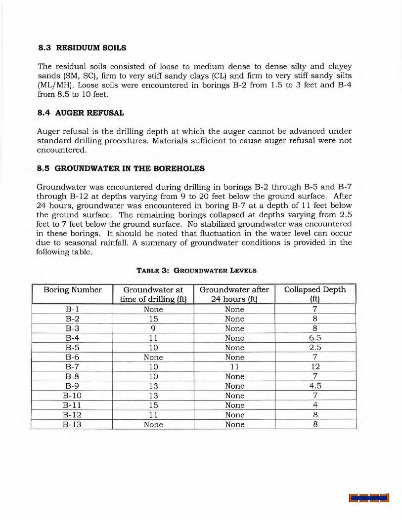
8.3 RESIDUUM SOILS
The residual soils consisted of loose to medium dense to dense silty and clayey sands (SM, SC), firm to very stiff sandy clays (CL) and firm to very stiff sandy silts (ML/MH) . Loose soils were encountered in borings B-2 from 1.5 to 3 feet and B-4 from 8 .5 to 10 feet.
8.4 AUGER REFUSAL
Auger refusal is the drilling depth a t which the auger cannot be advanced under standard drilling procedures. Materials sufficient to cause auger refusal were not encountered.
8.5 GROUNDWATER IN THE BOREHOLES
Groundwater was encountered during drilling in borings B-2 through B-5 and B-7 through B-12 at depths varying from 9 to 20 feet below the ground surface . After 24 hours, groundwater was encountered in boring B-7 at a depth of 11 feet below the ground surface. The remaining borings collapsed at depths varying from 2 .5 feet to 7 feet below the ground surface. No stabilized groundwater was encountered in these borings. It should be noted that fluctuation in the water level can occur due to seasonal rainfall. A summary of groundwater conditions is provided in the following table.
TABLE 3: GROUNDWATER LEVELS
Boring Number Groundwater at Groundwater after Collapsed Depth time of drilling (ft) 24 hours (ft) (ft)
B-1 None None 7 B-2 15 None 8 B-3 9 None 8 B-4 11 None 6.5 B-5 10 None 2.5 B-6 None None 7 B-7 10 11 12 B-8 10 None 7 B-9 13 None 4 .5
B-10 13 None 7 B-11 15 None 4 B-12 11 None 8 B-13 None None 8

9.0 SITE GRADING CONSIDERATIONS
Existing grades in the proposed development area vary from 250 feet (northern & central portions) to 230 feet (southern portion) above msl. Proposed grades are unknown at this time.
9.1 SITE PREPARATION
Site preparation activities would consist of the clearing of vegetation and stripping of any topsoil. In addition, site preparation should include removal of root masses to depths of up to 4 inches.
Following the stripping of the site, the site should be scarified and recompacted then proofrolled following the recommendations of Section 9.2.
9.2 SUBGRADE EVALUATION
The development area must be evaluated after the site has achieved the required elevation (cut areas) or prior to placing structural fill (fill areas). The evaluation should include proofrolling with a heavy vehicle with rubber tires. The proofrolling will help densify the near surface soils, and identify soils that may cause difficulty during final grading. All unsuitable material shall be removed or stabilized in place.
9.3 STRUCTURAL FILL
After the subgrade has been prepared and evaluated, engineered fill material can be placed to establish the proposed finished grades. Structural fill requirements can vary depending on the proposed development conditions. However, based on our experience with the anticipated development type, we recommend that structural fill be composed of soil with a maximum dry density of at least 95 pounds per cubic foot (pcf) as determined by the Standard Proctor Test (ASTM D-698), Liquid Limit (LL) less than 50 and Plasticity Index (PI) less than 25. Based on the testing performed and knowledge of other developments in the area, the majority of the soils encountered at the site should be suitable for structural fill. Soils classified as CH or MH should not be used in the upper 4 feet as they do not meet the plasticity criteria and can experience significant volume changes with varying moisture content. Fill material should be free of trash and other deleterious material and should not have stones larger then 3-inches in diameter.
9.4 GROUNDWATER CONTROL
Based on the groundwater depths observed, we do not anticipate the need for significant groundwater control at the site. Deep excavations, on the order of 8 to 10 feet or greater, could require groundwater control.

10.0 FOUNDATION RECOMMENDATIONS
Shallow foundations are likely foundation options based on the soil conditions encountered at the site. We would expect that structures could be constructed on residual soils or compacted structural fill with available soil bearing capacities ranging between 2,500 to 3000 psf. However, the use of shallow foundations will be dependent on loading conditions and settlement tolerances of the structure. This recommendation should be re-evaluated once details of the planned development are known.
Based on the information obtained from the soil test borings, we recommend using a Seismic Site Classification «D" in accordance with the 2006 International Building Code.
11.0 LIMITATIONS
The analyses, conclusions and recommendations presented in this report are based upon the preceding project information, and the results of this investigation. The borings at the site are widely spaced borings. While it is not likely that conditions will vary greatly from those observed in the borings, it is always possible that variations can occur between or away from borehole locations. It is recommended that additional borings be performed specific to the planned development.
This report has been prepared in accordance with generally accepted standards of geotechnical engineering practice. No other warranty is expressed or implied.

Google Earth Aerial
Photograph
PROJECT NO: PROJECT NAME I LOCATION:
C011277 Beck's Turf Farm #5 Tuske ee, Alabama
SCALE:
Geotechnical, Enviro nmental, and Materials Enginee rs

Important Information about Your
Geotechnical Engineering Report
Geotechnical Services Are Performed lor Specific Purposes, Persons, and Projects Geotechnical engineers structure their services to meet the specific needs of their clients. A geotechnical engineering study conducted for a civil engineer may not fulfil l the needs of a construction contractor or even another civil engineer. Because each geotechnical engineering study is unique, each geotechnical engineering report is unique, preparwt solely for the client. No one except you should rely on your geotechnicat engineering report without first conferring with the geotechnical engineer who prepared it. And no one - not even you - should apply the report for any purpose or project except the one originally contemplated.
Read the Full Report Serious problems have occurred because those relying on a geotechnical engineering report did not read it all. Do not rely on an executive summary. Do not read selected elements only.
A Geotechnical Engineering Report Is Based on A Unique Set of Project -SpecifiC Factors Geotechnical engineers consider a number of unique, project-specific factors when establ ish ing the scope of a study. Typical factors include: the client's goals, objectives, and risk management preferences; the general nature of the structure involved, its size, and configuration; the location of the structure on the site; and other planned or existing site improvements, such as access roads, parking lots, and underground utilities. Unless the geotechnical engineer who conducted the study specifically indicates otherwise, do not rely on a geotechnical engineering report that was: • not prepared for you, • not prepared for your project, • not prepared for the specific site explored, or • completed before important project changes were made.
Typical changes that can erode the reliability of an existing geotechnical engineering report include those that affect: • the function of the proposed structure, as when it's changed from a
parking garage to an office building, or from a light industrial plant to a refrigerated warehouse,
• elevation, configuration, location, orientation, or weight of the proposed structure,
• composition of the design team, or • project ownership.
As a general rule, always inform your geotechnical engineer of project changes-even minor ones- and request an assessment of their impact. Geotechnical engineers cannot accept responsibility or liability for problems that occur because their reports do not consider developments of which they were not informed.
Subsurface Conditions Can Change A geotechnical engineering report is based on conditions that existed at the time the study was performed. Do not rely on a geotechnical engineering report whose adequacy may have been affected by: the passage of time; by man-made events, such as construction on or adjacent to the site; or by natural events, such as floods, earthquakes, or groundwater fluctuations. Always contact the geotechnical engineer before applying the report to determine if it is still reliable. A minor amount of additional testing or analysis could prevent major problems.
Most Geotechnical Findings Are Professional Opinions Site exploration identifies subsurface conditions only at those points where subsurface tests are conducted or samples are taken. Geotechnical engineers review field and laboratory data and then apply their profess ional judgment to render an opinion about subsurface conditions throughout the site. Actual subsurface conditions may differ-sometimes significantlyfrom those indicated in your report. Retaining the geotechnical engineer who developed your report to provide construction observati on is the most effective method of managing the risks associated with unanticipated conditions.
A Report's Recommendations Are Not Final Do not overrely on the construction recommendations included in your report. Those recommendations are not final, because geotechnical engineers develop them principally from judgment and opinion. Geotechnical engineers can finalize their recommendations only by observing actual

subsurface conditions revealed during construction. The geotechnical engineer who developed your report cannot assume responsibility or liability for the report's recommendations if that engineer does not perform construction observation.
A Geotechnical Engineering Report Is Subject to Misinterpretation Other design team members' misinterpretation of geotechnical engineering reports has resulted in costly problems. Lower that risk by having your geotechnical engineer confer with appropriate members of the design team after submitting the report. Also retain your geotechnical engineer to review pertinent elements of the design team's plans and specifications. Contractors can also misinterpret a geotechnical engineering report. Reduce that risk by having your geotechnical engineer participate in prebid and preconstruction conferences, and by providing construction observation.
Do Not Redraw the Engineer's Logs Geotechnical engineers prepare final boring and testing logs based upon their interpretation of field logs and laboratory data. To prevent errors or omissions, the logs included in a geotechnical engineering report should never be redrawn for inclusion in architectural or other design drawings. Only photographic or electronic reproduction is acceptable, but recognize that separating logs from the report can elevate risk.
Give Contractors a Complete Report and Guidance Some owners and design professionals mistakenly believe they can make contractors liable for unanticipated subsurface conditions by limiting what they provide for bid preparation. To help prevent costly problems, give contractors the complete geotechnical engineering report, but preface it with a clearly written letter of transmittal. In that letter, advise contractors that the report was not prepared for purposes of bid development and that the report's accuracy is limited; encourage them to confer with the geotechnical engineer who prepared the report (a modest fee may be required) and/or to conduct additional study to obtain the specific types of information they need or prefer. A prebid conference can also be valuable. Be sure contractors have sufficient time to perform additional study. Only then might you be in a position to give contractors the best information available to you, while requiring them to at least share some of the financial responsibilities stemming from unanticipated conditions.
Read Responsibility Provisions Closely Some clients, design professionals, and contractors do not recognize that geotechnical engineering is far less exact than other engineering disciplines. This lack of understanding has created unrealistic expectations that
have led to disappointments, claims, and disputes. To help reduce the risk of such outcomes, geotechnical engineers commonly include a variety of explanatory provisions in their reports. Sometimes labeled 'limitations" many of these provisions indicate where geotechnical engineers' responsibilities begin and end, to help others recognize their own responsibilities and risks. Read these provisions closely Ask questions. Your geotechnical engineer should respond fully and frankly.
Geoenvironmental Concerns Are Not Covered The equipment, techniques, and personnel used to perform a geoenvironmental study differ significantly from those used to perform a geotechnical study. For that reason, a geotechnical engineering report does not usually relate any geoenvironmental findings, conclusions, or recommendations; e.g., about the likelihood of encountering underground storage tanks or regulated contaminants. Unanticipated environmental problems have led to numerous project failures. If you have not yet obtained your own geoenvironmental information, ask your geotechnical consultant for risk management guidance. Do not rely on an environmental report prepared for someone else.
Obtain Professional Assistance To Deal with Mold Diverse strategies can be applied during building design, construction, operation, and maintenance to prevent significant amounts of mold from growing on indoor surfaces. To be effective, all such strategies should be devised for the express purpose of mold prevention, integrated into a comprehensive plan, and executed with diligent oversight by a professional mold prevention consultant. Because just a small amount of water or moisture can lead to the development of severe mold infestations, anumber of mold prevention strategies focus on keeping building surfaces dry. Whi le groundwater, water infiltration, and similar issues may have been addressed as part of the geotechnical engineering study whose fi ndings are conveyed in this report, the geotechnical engineer in charge of this project is not a mold prevention consultant; none of the services performed in connection with the geotechnical engineer's study were designed or conducted for the purpose of mold prevention. Proper implementation of the recommendations conveyed in this report will not of itself be sufficient to prevent mold from growing in or on the structure involved.
Rely on Your ASFE-Member Geotechnical Engineer lor Additional Assistance Membership in ASFE!The Geoprofessional Business Association exposes geotechnical engineers to a wide array of risk management techniques that can be of genuine benefit for everyone involved with a construction project. Confer with your ASFE-member geotechnical engineer for more information.
ASFE THE GEOPROFESSIONAL BUSINESS ASSOCIATION
8811 Colesville Road/Suite G106, Silver Spring, MD 20910 Telephone: 301/565-2733 Facsimile: 301/589-2017
e-mail: [email protected] www.asfe.org
Copyright 2004 by ASFE, Inc. Duplication, reproduction, or copying of this document, in whole or in part, by any means whatsoever. is strictly prohibited, except with ASFE's specific written permission. Excerpting, quoting, or otherwise extracting wording from this document is permitted only with the express written permission of ASFE, and only for
purposes of scholarly research or book review. Only members of ASFE may use this document as a complement to or as an element of a geotechnical engineering report. Any other firm, individual, or other entity that so uses this document without being an ASFE member could be committing negligent or intentional (fraudulent) misrepresentation.
IIGER01115.0MRP

SOIL CLASSIFICATION CHART
MAJOR DIVISIONS SYMBOLS
GRAPH LETIER
COARSE GRAINED
SOILS
MORE THAN 50% OF MATERIAL IS LARGER THAN NO. 200 SIEVE
SIZE
FINE GRAINED
SOILS
MORE THAN 50% OF MATERIAL IS SMALLER THAN NO. 200 SIEVE
SIZE
GRAVEL AND
GRAVELLY SOILS
CLEAN GRAVELS
GRAVELS WITH MORE THAN 50% FINES
OF COARSE FRACTION
RETAINED ON NO.
,-~·-:aa ....•. .,. ). ··~ ....... , •••• a
111..- • 1!!.::"
4 SIEVE (APPRECIABLE I• AMOUNT OF FINES) I '
SAND AND
SANDY SOILS
CLEAN SANDS
(UTILE OR NO FINES)
SANDS WITH MORE THAN 50% FINES
OF COARSE FRACTION
PASSING ON NO. 4 SIEVE (APPRECIABLE
SILTS AND
CLAYS
SILTS AND
CLAYS
AMOUNT OF FINES)
LIQUID LIMIT LESS THAN 50
LIQUID LIMIT GREATER THAN 50
'
''· ... ,, , ,
GW
GP
GM
GC
sw
SP
SM
sc
ML
OL
MH
HIGHLY ORGANIC SOILS PT
NOTE: DUAL SYMBOLS ARE USED TO INDICATE BORDERLINE SOIL CLASSIFICATIONS
TYPICAL DESCRIPTIONS
WELL-GRADED GRAVELS. GRAVELSAND MIXTURES. UTILE OR NO FINES
POORLY-GRADED GRAVELS, GRAVEL- SAND MIXTURES, UTILE ORNO FINES
SILTY GRAVELS, GRAVEL- SAND SILT MIXTURES
CLAYEY GRAVELS. GRAVEL - SAND CLAY MIXTURES
WELL-GRADED SANDS, GRAVELLY SANDS. UTILE OR NO FINES
POORLY-GRADED SANDS, GRAVELLY SAND, UTILE OR NO FINES
SIL TV SANDS. SAND - SILT MIXTURES
CLAYEY SANDS, SAND - CLAY MIXTURES
INORGANIC SILTS AND VERY FINE SANDS. ROCK FLOUR, SILTY OR CLAYEY FINE SANDS OR CLAYEY SILTS WITH SLIGHT PLASTICITY
INORGANIC CLAYS OF LOW TO MEDIUM PLASTICITY, GRAVELLY CLAYS, SANDY CLAYS, SIL TV CLAYS. LEAN CLAYS
ORGANIC SILTS AND ORGANIC SIL TV CLAYS OF LOW PLASTICITY
INORGANIC SILTS. MICACEOUS OR DIATOMACEOUS FINE SAND OR SILTY SOILS
INORGANIC CLAYS OF HIGH PLASTICITY
ORGANIC CLAYS OF MEDIUM TO HIGH PLASTICITY. ORGANIC SILTS
PEAT, HUMUS, SWAMP SOILS WITH HIGH ORGANIC CONTENTS

BUILDING & EARTH SCIENCES, INC.
BORING LOG DESCRIPTION
Building & Earth Sciences, Inc. (BESI) used the giNT software program to prepare the attached boring logs. The giNT program provides the flexibility to custom design the boring logs to include the pertinent information from the subsurface exploration and results of our laboratory analysis. The soil and laboratory information included on our logs is summarized below:
Depth The depth below the ground surface is shown.
Sample Type The method used to collect the sample is shown. The typical sampling methods include Split Spoon Sampling, Shelby Tube Sampling, Grab Samples, and Rock Core. A key is provided at the bottom of the log showing the graphic symbol for each sample type.
Sample Number Each sample collected is numbered sequentially
Blows per 6", REC%, RQD% When Standard Split Spoon sampling is used, the blows required to drive the sampler each 6-inch increment are recorded and shown in column 4. When rock core is obtained the recovery ration (REC%) and Rock Quality Designation (RQD%) is recorded.
Soil Data Column 5 is a graphic representation of 4 different soil parameters. Each of the parameters use the same graph, however, the values of the graph subdivisions vary with each parameter. Each parameter presented on column 5 is summarized below:
• N-Value- The Standard Penetration Test N-Value, obtained by adding number of blows required to drive the sampler the final12 inches, is recorded. The graph labels range from 0 to 50.
• Qu - Unconfined Compressive Strength estimate from the Pocket Penetrometer test in tons per square foot (tsD. The graph labels range from 0 to 5 tsf.
• Atterberg Limits -The Atterberg Limits are plotted with the plastic limit to the left, and liquid limit to the right, connected by a horizontal line. The difference in the plastic and liquid limits is referred to as the Plasticity Index. The Atterberg Limits test results are also included in the Notes column on the far right column of the boring log. The Atterberg Limits graph labels range from 0 to 100.
• %Moisture- The Natural Moisture Content of the soil sample as determined in our laboratory.
Soil Description The soil description prepared in accordance with ASTM D 2488, Visual Description of Soil Samples. The Munsel Color chart is used to determine the soil color. Strata changes are indicated by a solid line, with the depth of the change indicated on the left side of the line. If subtle changes within a soil type occur, a broken line is used. The Boring Termination or Auger Refusal depth is shown as a solid line at the bottom of the boring.
Graphic The graphic representation of the soil type is shown. The graphic used for each soil type is related to the Unified Soil Classification chari. A chari showing the graphic associated with each soil classification is included.
Remarks Remarks regarding borehole observations, and additional information regarding the laboratory results and groundwater observations.

BUILDING & EARTH SCIENCES, INC. 5045 Milgen Court, Unit# 2 Columbus, GA 31907
LOG OF BORING: B-01 Sheet I of I
Project Name: Beck's Turf Farm 5 (Site #3) Project Number: CO I 1277
Project Location: Tuskegee, Alabama Date Drilled: I 0/27/ 1 I
Drilling Method: Hollow Stem Auger Surface Elevation: Boring Location: North-Central Area of North Tract of Site
t..Ll
€ Q.. 0 >- ;z BLOWS f-
:c t..Ll t..Ll PER 6" f- ...l ...l
REC% Q.. Q.. Q..
t..Ll :E :2 RQD% a <( <( Vl Vl
X I 5-7-8 ,_
~ 2 3-7-7
R 3 9-12- 13 5- r---
<--: IX 4 8-9-10 '---'
X 5 6-7-8 10 - ~
~ X 6 8-1 9-2 1 1 5 -~
<---c IX 7 15-30-3 1 ~ 20 -r---
b ~
iii w m ...., Cl. ~
~ w 25 -t-§. , ::;:
~ u. lr ::> t-(/)
D N-Value D 10 20 30 40
.._ Qu (tsf) .._ I 2 3 4 I Atterberg Limits I 20 40 60 80
• %Moisture • 20 40 60 80
8.0
12.0
\
» []20.0
SOIL DESCRIPTION
SILTY SAND: medium dense, light brown, fine (SM)
CLAYEY SAND: medium dense, tan, fine (SC)
CLAYEY SILT: hard, red and white (ML)
Boring terminated @ 20' No groundwater was encountered at time of boring or after 24 hours Borehole collapsed to 7' after 24 hours
REMARKS
!
I
S< ~r-~~--~---=~L-----------------~----------------------------------~---L------------------_, m SAMPLE TYPE [gj Split Spoon ~r-----------~~~~--------------------------------------------------------------------------_,
~ N-VALUE STANDARDPEN ETRATIONRESISTANCE (ASTMD-1586) REC RECOVERY ~ % ~IOISTURE PERCENT NATURAL MOISTURE CONTENT RQD ROCK QUALITY DESIGNATION ~ 5j.. GROUNDWATER LEVEL IN THE BOREHOLE UD UNDISTURBED ~ g Qu UNCON FINED COMPRESSIVE STRENGTH ESTIMATE FROM POCKET PENETROMETER TEST
llirmineham 5545 Derby Dr
Birmingham, AL 352 10
Columbus 5045 Mileen Ct Unit 2 Columbus, GA 31907
Tulsa 10828 E. Newton St #Ill
Tulsa, OK 74 116
Atlanta 4124 Daniel Green Trail
Smyrna, GA 30080
Savannah 391 1 Old Louisville Rd #107
Garden City, GA 31408

BUILDING & EARTH SCIENCES, INC. 5045 Milgen Court, Unit# 2 Columbus, GA 31907
LOG OF BORING: B-02 Sheet I of I
Project Name: Beck's Turf Farm 5 (Site #3) Project Number: C011 277
Project Location: Tuskegee, Alabama Date Drilled: 10/27/ 11
Drilling Method: Hollow Stem Auger Surface Elevation : Boring Location: Central Area of North Tract of Site
w 2
c.. 0 >- ;z. BLOWS ~ E-:r: w w PER6" ...J f- ...J c.. REC% 0... c.. r..tJ
~ ::;t RQD % a -<
(/) (/)
IX I 3-3-3 J:----c
~ 2 1-1-1
t----,
~ 3 2-3-3 5-
'"""'X 4 3-4-5 '------'
r----c X 5 4-3-3 10 -'------'
r----c X 6 5-8-12 15 - '----'
t----,
\
0 N-Value 0 10 20 30 40
.&. Qu (tsf) .&. I 2 3 4 I Atterberg Lim its I 20 40 60 80
e % Moisture e 20 40 60 80
SOIL DESCRIPTION
SANDY SILT: firm, light brown, fine (ML)
II 1.5 CLAYEY SAND: very loose, light tan, fi ne //
3.0 (SC) / ?/, SILTY SAND: loose, light tan and gray, fine (SM)
c--l1Q_ SiLTY SAND: n1ediu n1dense,\vhlte and-- ---+-----1 gray, fine (SM)
REMARKS
Lab Resulls for 3.5' - 5' % Passing #200 Sieve: 46.7 Moisture Content: 18.1 %
IX 7 3-5-6 ~ 20 -r--- 20.0
f-0 (!)
Ui w "' ...., 0.. (!)
Boring terminated @ 20' Groundwater was encountered @ 15' at time of boring but was not present after 24 hours Borehole collapsed to 8' after 24 hours
f[ w 25 -t:: ~
"' ~ <{ LL LL oc :::> f(/)
s.: hl ~--L-L--L---=~~------------------L-------------------------------------~--~------------------~ "' SAMPLE TYPE (:8J Split Spoon ~ ~-----------=~~--~----------------------------------------------------------------------------~
~ N-VALUE STANDARD PENETRA TION RESISTA NCE (ASTM D-1 586) 0
"' LL 0
%MOISTURE PERCENT NATURAL MOISTURE CONTENT
S,Z GROUNDWATER LEVEL IN THE BOREHOLE
REC RECOVERY
RQD ROCK QUALITY DESIGNATION
UD UNDISTURBED
g Qu UNCONFINED COMPRESSIVE STRENGTH ESTIMATE FROM POCKET PENETROMETER TEST ~~~--------~~~~~~~~~~~~~~~~~~~~~------~------~----------------------------~
Birmingham 5545 Derby Dr
Birmingham, AL 35210
Columbus 5045 Milgcn Ct Unit 2 Columbus, GA 31907
Tulsa 10828 E. Newton St #Ill
T ulsa, OK 74 11 6
Atlanta 4124 Daniel Green Trail
Smyrna, GA 30080
Savannah 3911 O ld Louisville Rd #107
Garden City, GA 31408

BUILDING & EARTH SCIENCES, INC. 5045 Milgen Court, Unit # 2 Columbus, GA 31907
LOG OF BORING: B-03 Sheet I of I
Project Name: Beck's Turf Farm 5 (Site #3) Project Number: CO I I277
Project Location: Tuskegee, Alabama Date Dr illed: 10/27/ 11
Drilling Method: Hollow Stem Auger Surface Elevation: Boring Location: South-Central Area ofNorth Tract of Site
w 0 2'
Q..
>- ;z BLOWS ~ f-:c w w PER 6" ....l f- ....l Q.. REC% Q.. Q.. w ::E ::E RQD% 0 < <
Vl Vl
~ I 2-3-3
~ 2 2-3-4
R 3 7-1 2- 17 5 - I--
r-,
X 4 6-7-9 '---'
X 5 4-5-2 10 - '---'
.--;
X 6 7-8-9 15 -'---'
0 N-Value 0 10 20 30 40
A Qu (tsl) A I 2 3 4 I Atterberg Limits I
20 40 60 80 e %Moisture e
20 40 60 80
SOIL DESCRIPTION
SANDY SILT: fim1, light brown, fine (ML)
1.5
u :c Q..
~ 0
I I
REMARKS
SILTY SAND: loose, light brown, fine (SM) Lab Results for 1.5' - 3' % Passing #200 Sieve: 34.9
__1,Q__ -------- ---- -- ---- ---+--1 Moisture Content: 12.3% SILTY SAND: medium dense, light brown, fine, with trace rock (SM)
~------ -------- - -- -----t---1 SIL TY SAND: loose, light brown, fine (SM)
12.0
'Sl
SANDY SILT: very stilT, brown, fine, with partially weathered rock (ML)
~------------ - --- - -SANDY SILT: hard, light brown, fine (ML) ----t-H-IH
.--; X 7 8- 12-2 1 ~ 20-~ 20.0
..., c.. (!)
;;; ~ 25 -1-§.
"' ::;'
~ u. 0: ::> 1-C/)
Boring terminated @ 20' Groundwater was encountered @ 9' at time of boring but was not present after 24 hours Borehole collapsed to 8' after 24 hours
~
~r--L-L--L-~=-~---------L-------------------~-~--------------~ m SAMPLE TYPE ~ Split Spoon ~r------~~~-~-------------------------------------------~
~ N-VALUE STANDARD PENETRATION RESISTANCE (ASTM D- 1586) REC RECOVERY
~ % MOISTURE PERCENT NATURAL MOISTURE CONTENT RQD ROCK QUALITY DESIGNATION
~ 'Q GROUNDWATER LEVEL IN THE BOREHOLE l!D UNDISTURBED (!)
g~Q~u _____ U_N_C_O_N_F_IN_E_D_C_O_M_P_R_E_S_SI_V_E_S_TR_E_N_G_T_H_E_-S_T_IM_A_T_E_F_R_O_M_l_'O_C_K_E_T_P_EN_E_T_R_O_M_E_T_E_R_T_ES_T _____________________ ~
Birmi ngham 5545 Derby l)r
Birming ham, AL 35210
C olumbus 5045 Milgcn Ct Unit 2 Columbus, GA 31907
Tu lsa 10828 E. Newton St # Ill
Tulsa, OK 74 116
Atlanta 4 124 l)aniel Green Trail
Smyrna, GA 30080
Savannah 3911 O ld Louisville Rd #107
Garden City, GA 31408

-. 0.. (.!)
BUILDING & EARTH SCIENCES, INC. 5045 Milgen Court, Unit# 2 Columbus, GA 31907
LOG OF BORING: B-04 Sheet I of I
Project Na me: Beck's Turf Farm 5 (Site #3) Project Number: COI I277
Project Location: Tuskegee, Alabama Date Drilled: 10/27/1 1
Drilling Method: Hollow Stem Auger Surface Elevation: Boring Location: Southwest Area of North-Centra l Tract of Site
U.J
g 0.. 0 >- z BLOWS f-::c U.J PER6" U.J ...l f- ...J REC% 0.. 0..
0..
U.J 2 2 RQD% Cl -< -< (/) (/)
X I 5-4-3 (---
X 2 3-4-5 '--
r-
X 3 4-4-4 5 - '--
R 4 2-3-2 r-
~ 5 1-2-2 10 - r-
R 6 2-5-5 15 - r-
.........,
20 -~ 7 5-6-7
0 N-Value 0 10 20 30 40
.., Qu (tsf) .., I 2 3 4 I At1erberg Limits I
20 40 60 80
• % Moisture • 20 40 60 80
[\
p
~
J
EtJ
1:\J
SOIL DESCRIPTION
-o:3\ TOPSOIL SANDY SILT: stiff, dark brown, fine (ML)
3.0 SILTY SAND: loose, brown, fine (SM)
~-------------- -- - -
20.0
SILTY SAND: loose to medium dense, light brown, fine (SM)
'Sl.
IJoring terminated @ 20' Groundwater was encountered @ I I' at time of boring but was not present af1er 24 hours Borehole collapsed to 6.5' af1er 24 hours
u ::c 0.. REMARKS ~ 0
Lab Results for 3.5' · 5' % Passing #200 Sieve: I 0. I
I Moisture Content: 7.6%
\1 ~ 25 -~ "' :;;
~ u. u. tr ::::> f-(/)
;.: hl~--L-L--L---r=>~------------------L-------------------------------------~--~------------------~ CD SAMPLE TYPE ~ Split Spoon Nf------------~~----------------------------------------------------------------------------------~ (.!)
N-VALUE STANDARD PENETRATION RESISTANCE (ASTM D-1586) REC RECOVERY z ;:;: 0 CD % ~IOISTURE PERCENT NATURAL MOISTURE CONTENT RQD ROCK QUALITY DESIGNATION l5 'Sj. GROUNDWATER LEVEL IN THE BOREHOLE UD UNDISTURBED (.!)
g Qu UNCONFINED COMPRESSIVE STRENGTII ESTIMATE FROM POCKET PENETROMETER TEST
Birmingham 5545 Derby Dr
Birmingham, AL 352 10
Columbus 5045 Milgen Ct Unit 2 Columbus, GA 31907
Tulsa 10828 E. Newton St #I I I
Tulsa, OK 74 11 6
Atlanta 4124 Daniel Green Trail
Smyrna, GA 30080
Savannah 391 I Old Louisville Rd #107
Garden City, GA 31408

v; w
"' .... 0.. (!)
BUILDING & EARTH SCIENCES, INC. 5045 Milgen Court, Unit # 2 Columbus, GA 31907
LOG OF BORING: B-05 Sheet I of I
Project Name: Beck's Turf Farm 5 (Site #3) Project Number: C0 11277
Project Location: Tuskegee, Alabama Date Drilled: 10/27/11
Dr illing Method: Hollow Stem Auger Surface Elevation: Boring Location: Southeast Area of North-Central Tract of Site
u.J
g c.. 0 >- z BLOWS f-:c u.J u.J PER 6" ...J f- ...J c.. REC% c.. c.. u.J :a :a RQD % 0 -< -< (/)
(/)
~ I 3-4-5
~ 2 3-4-4
r-; IV 3 2-3-4
5-16 "X 4 2-2-3 <......-'
r-;
X 5 3-6-7 I 0 -'----'
r:
1 5 -~ 6
r:
20 -~ 7
3-5-7
10- 14-15
8- 10- 11
0 N-Value 0 10 20 30 40
"' Qu (tsf) "' I 2 3 4 I Atterberg Limi ts I 20 40 60 80
• % Moisture • 20 40 60 80
~ p
~] 1-1
p
[~
\ I
q
SOIL DESCRIPTION
SANDY CLAY: firm to stiff, brown, fine (CL)
u i c.. -< ~ (.J
REMARKS
Lab Results for 3.5' - 5' Atterberg Limits
__2d_ __________ ______ __ -----J<.f¥1j"' Liquid Limit: 55.4 SILTY CLAY: finn, gray and brown, fine Plastic Limit: 32 (MH) Plasticity Index: 24
Classi fication: MH ~----"8"''0"---;S"'t'L T"'Y......-rS"A'N"'D' :_t_ne-d..-iu_n_1'de-n-se-,'"li'gt""Jt'b-ro_w_t1-, ------+"-.._.__, Lab Results for 6' - 7.5'
fine (SM) %Passing #200 Sieve: 75.3 Moisture Content: 29.4%
'Sl.
.l1Q_ - - - - - - - - - - - - - - - - - - -----t--:-1--,-; SIL TY SAND: medium dense, light brown,
22.0
fine, with partially weathered rock (SM)
SAND: medium dense, light brown, coarse grain, poorly graded (SP)
\1 <---c
~ 30-~ 9 8- 12-15
"' ::;
~ LL LL a: ;;) >-(/)
30.0 Doring tem1inated @ 30' Groundwater was encountered @ 10' at time of boring but was not present after 24 hours Borehole collapsed to 2.5' after 24 hours
5o< hl~~~~-L---=~~------------------~------------------------------------~--~------------------~ "' SAMPLE TYPE ~ Split Spoon ~r------------=~----------------------------------------------------------------------------------~ ~ N-V ALliE STANDA RD PENETRATION RESISTANCE (ASTM 0- 1586) 0
"' % MOISTU R E PERCENT NATURAL MOISTURE CONTENT
~ 'S/. GROUNDWATER LEVEL rN THE BOREHO LE
REC RECOVERY
RQO ROCK QUALITY DESIGNATION
liD UNDISTURBED
g~Q~tl~' --------~U~N~C~O_N_F_IN_E_D_C~O~M_P_R_E~S_SI_V~E~S_TR_E~0N~G~T_H_E~·S_T_IM_A_l_·E_F_R~O_M_I~'O~C_K_E_T_P_EN_E_-T_R_O_M_E_T_E_R_T_ES_T ______________________________ ~
Birmingham 5545 Derby Or
Birmingham, AL 35210
Columbus 5045 i\'lilgen Ct Unit 2 Columbus, CA 31907
Tulsa 10828 E. Newton St #Ill
Tulsa, OK 74 116
Atlanta 4124 Daniel Green Trail
Smyrna, CA 30080
Savannah 3911 Old Louisville Rd #107
Carden City, CA 31408

BUILDING & EARTH SCIENCES, INC. 5045 Milgen Court, Unit# 2 Columbus, GA 31907
LOG OF BORING: B-06 Sheet I of I
Project Name: Beck's Turf Fann 5 (Site #3) Project Nu mber: C011277
Project Locat ion: Tuskegee, Alabama Date Drilled : 10/28/11
Drilling Method: Hollow Stem Auger Surface Elevation: Boring Location: East-Central Area of South-Central Tract of Site
t..Ll ~
Q.. ci ~ >- ;z: BLOWS E-:c t..Ll t..Ll PER 6" E- ...l
...l REC% Q.. Q..
Q..
t..Ll ~ ~ RQD% a < < (/) (/)
~ I 5-6-6
IX 2 5-6-7 ~
~ 3 5-8-7 5- ~
r-
X L_
4 5-7- II
r-
X 5 8-13-1 4 10 - '--
f\7 6 1/\ 9-16-17 15-r--
c--c X 7 15-1 8-21 ~ 20 -~
b (!)
u; w m ..., a.. (!)
;:; ~ 25 -§.
"' ::; ~ LL. LL. a:: => ,_ (/)
S<
0 N-Value 0 10 20 30 40
.&. Qu (tsf) .&.
I 2 3 4 I Atterberg Limits I 20 40 60 80
• %Moisture • 20 40 60 80
SOIL DESCRIPTION
SILTY SAND: medium dense, tan, fine 1.5 (SM)
3.0
8.0
12.0
17.0
20.0
SANDY SILT: stiff, tan, fine (ML)
SILTY SAND: medium dense, tan, fine (SM)
CLAYEY SILT: very stiff, red (ML)
SANDY CLAY: very stiff, red and gray, fine (CL)
SILTY SAND: dense, multicolored, fine (SM)
Boring tem1inated @ 20' No groundwater was encountered at time of boring or after 24 hours Borehole collapsed to 7' after 24 hours
u :c Q..
~ 0
l I
I I
REMARKS
Lab Results for 3.5' - 5' %Passing #200 Sieve: 18.8 Moisture Content: 13.0%
~r---L-L__L __ ~=>~ __________________ L_ ____________________________________ J_ __ J_ __________________ ~
m SAMPLE TYPE (2J Split Spoon N
(!)
~ N-V ALliE STANDARD PENETRATION RESISTANCE (ASTM D-1586) REC RECOVERY g % MOISTURE PERCENT NATURAL MOISTURE CONTENT RQD ROCK QUALITY DESIGNATION ~ (!)
'¥. GROUNDWATER LEVEL IN THE BOREHOLE liD UNDISTURBED o Q u UNCONFINED COM PRESSIVE STRENGTH ESTIMATE FROM POCKET PENETROMETER TEST ~ L-~----------------------------------------------------------------------------------------------~
Birmingham 5545 Derby Dr
Birmingham, AL 35210
Columbus 5045 Milgen Ct Unit 2 Columbus, GA 31907
T ulsa 10828 E. Newton St #Il l
Tulsa, OK 741 16
Atlanta 4124 Daniel Green T rail
Smyrna, GA 30080
Savannah 3911 Old Louisv ille Rd #107
Garden City, GA 31408
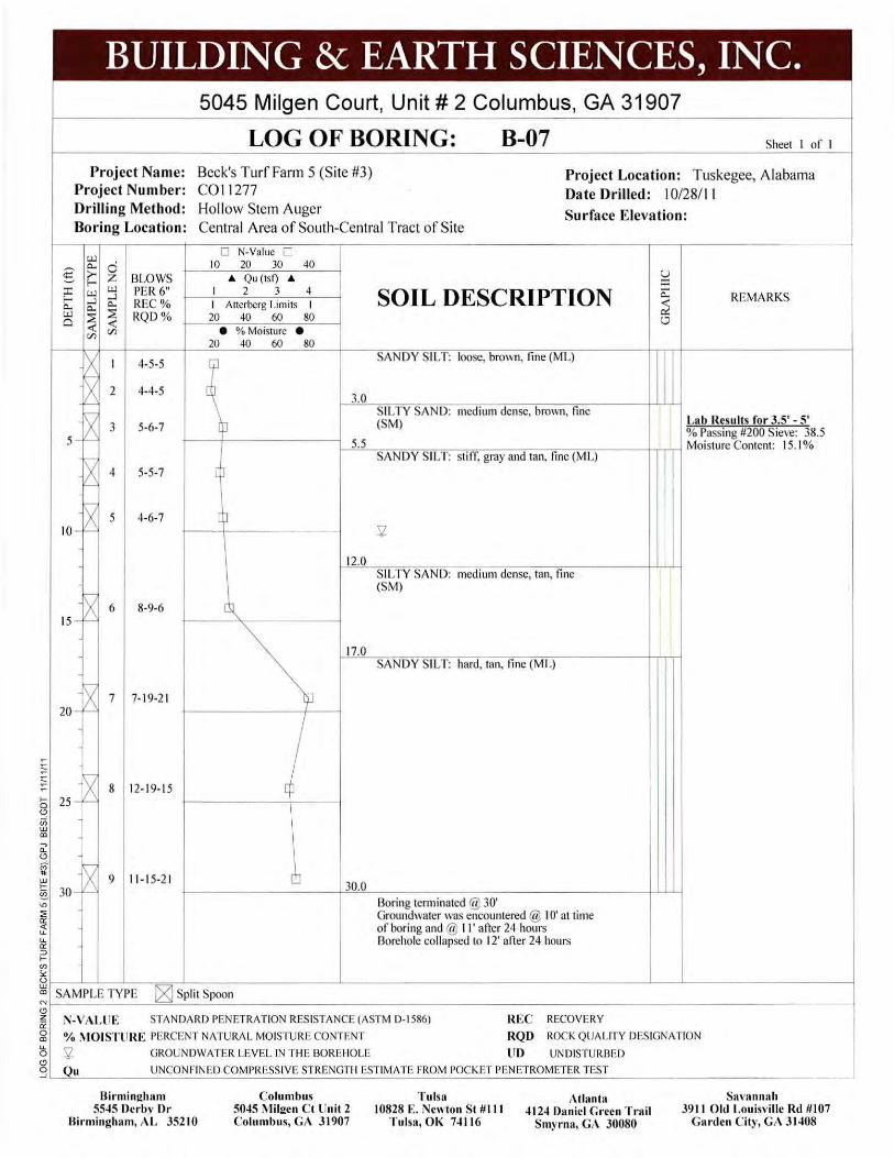
BUILDING & EARTH SCIENCES, INC. 5045 Milgen Court, Unit# 2 Columbus, GA 31907
LOG OF BORING: B-07 Sheet I of I
Project Name: Beck's Turf Farm 5 (Site #3) Project Number: C01 1277
Project Location: Tuskegee, Alabama Date Drilled: 10/28/1 1
Drilling Method: Hollow Stem Auger Surface Elevation: Boring Location: Central Area of South-Central Tract of Site
u..l
€ Q.., 0 >- ;z f--
:c u..l u..l --l f-- --l Q.., Q.., Q..,
u..l 2 2 a <C <C r/l r/l
~ I
~ 2
BLOWS PER6" REC% RQD %
4-5-5
4-4-5
0 N-Value 0 10 20 30 40
& Qu (tsf) &
I 2 3 4 I Atterberg Limits I 20 40 60 80
e % Moisture e 20 40 60 80
SOIL DESCRIPTION
SANDY SILT: loose, brown, fine (ML)
3.0
u :c Q..,
~ 0
REMARKS
X 3 5 - '---'
5-6-7 SILTY SAND: medium dense, bro\\11, fine (SM) Lab Results for 3.5' - 5'
% Passing #200 Sieve: 38.5 I--"'5'-".5___,C"':":"=-=-~-=-=-c=----,----;;----,--;-;-;----t...,:..,.....--i Moisture Content: 15. 1%
SANDY SILT: stiff, gray and tan, fine (M L)
X 4 5-5-7 '---'
X 5 4-6-7 10 - '---'
~X 6 8-9-6 15-'-
<-IX 1 7- 19-21 20 -1'--
........,
IX s 12- 19- 15 :::; 25 - 1'--0 Cii w CD ..., Q.
0
~ <-w IX 9 11-1 5-21 ~ 30-r "' ::E a:: <( u. u. a:: :::> I-V)
0
[
12.0
17.0
I cp
30.0
SIL TV SAND: medium dense, tan, fine (SM)
SANDY SILT: hard, tan, fine (ML)
13oring tenninated @ 30' Groundwater was encountered @ I 0' at time of boring and @ II ' afier 24 hours 13orehole collapsed to 12' afier 24 hours
!
S< hl~~~-J_-~~~--------~-----------------~--L----------1 CD SAMPLE TYPE [g) Split Spoon ~~-------~~---------------------------------------~ z a: 0 CD
N- V ALliE STANDA RD PENETRATION RESISTANCE (A STM 0-1586)
%MOISTURE PERCENT NATURAL MOISTURE CONTENT
l) '5l GROUNDWATER LEVEL IN THE 130 REIIOLE
REC RECOVERY
RQD ROCK QUA LITY DESIGNATION
liD UNDISTURBED 0 g Qu UNCONFINED COMPRESSIV E STRENGTH ESTIMATE FROM POCKET PENETROMETER TEST
Birmingham 5545 Derby Dr
Birmingham, r\L 35210
Colu mbus 5045 Milgen Ct Unit 2 Colu mbus, GA 31907
Tulsa 10828 E. Newton St #Ill
T ulsa, OK 74 116
Atlanta 4124 Daniel Green Trail
Smyrna, GA 30080
Sava nnah 39 11 Old Louisville Rd #107
Garden C ity, GA 31408

BUILDING & EARTH SCIENCES, INC. 5045 Milgen Court, Unit# 2 Columbus, GA 31907
LOG OF BORING: B-08 Sheet I of I
Project Name: Beck's Turf Farm 5 (Site #3) Project Num ber: CO I 1277
Project Location: Tuskegee, Alabama Date Drilled: 10/28/ 11
Drilling Method: Hollow Stem Auger Boring Location: West-Central Area of South-Central Tract of Site
Surface Elevation:
u..l 0 N-Value 0
~ c.. ci 10 20 30 40
5 >- z BLOWS & Qu (tsf) & u E-
:r:: u..l u..l PER6" I 2 3 4 SOIL DESCRIPTION :r::
....l c.. REMARKS E- ....l c.. REC% I Atterberg Limits I ~ c.. c.. u..l ::2 ::2 RQD % 20 40 60 80 " 0 ~
Q ~ (/) • %Moisture • (/)
20 40 60 80
X I 7-7-9 SANDY SILT: very stiff to stiff, light brown and tan, fine (ML)
X 2 5-5-4 q ~
x 3 4-5-6 p 5 - ~ 5.5
x SILTY SAND: medium dense, tan, fine
4 4-5-6 EP (SM)
'------' 8.0
~ SAND: medium dense, orange, coarse grain,
5 5-7·7 QJ poorly graded (SP)
10 - f-- 5l
12.0 SANDY SILT: stiff, tan, fine (ML)
~ 6 15 - f--
5-6-7
__!1Q_ ---- - ----- -------- ---t-t-H-1 SANDY SILT: very stiff, gray, fine (ML)
~ 7 1/\ 9-1 5-14 ~ 20 -f-- 20.0
~
>--0 (!)
u; w CD -, "(!)
Boring terminated @ 20' Groundwater was encountered @ I 0' at time of boring but was not present afler 24 hours Borehole collapsed to 7' afler 24 hours
\1 lU 25 ->--§.
"' ::;;
~ LL LL a: ;:)
>-(/)
Sc: ~~--~L__L __ ~=-~------------------L-------------------------------------~--~------------------~ CD SAMPLE TYPE C8J Split Spoon ~~----------~~~--~----------------------------------------------------------------------------~
~ N-VALUE STANDARD PENETRATION RESISTANCE (ASTM D-1586) 0 CD u. 0
%MOISTURE PERCENT NATURAL MOISTURE CONTENT 5j. GROUNDWATER LEVEL IN THE BOREHOLE
REC RECOVERY RQD ROCK QUALITY DESIGNATION
UD UNDISTURBED g Qu UNCONFIN ED COMPRESSIVE STRENGTH ESTIMATE FROM POCKET PENETROMETER TEST ~L_~----------------------------------------------------------------------------------------------~
Birmingham 5545 Derby Dr
Birmingham, AL 3521 0
Columbus 5045 Milgen Ct Unit 2 Columbus, GA 3 1907
Tulsa 10828 E. Newton St #I ll
Tulsa, OK 7411 6
Atlanta 4124 Daniel Green Tra il
Smyrna, GA 30080
Savannah 391 1 Old Louisville Rd #107
Garden City, GA 31408

,__ 0 <.? (ii UJ Q)
-. Q.
<.?
BUILDING & EARTH SCIENCES, INC. 5045 Milgen Court, Unit# 2 Columbus, GA 31907
LOG OF BORING: B-09 Sheet I of I
Project Name: Beck's Turf Farm 5 (Site #3) Project Number: C011277
Project Loca tion: Tuskegee, Alabama Date Drilled: 10/28/ 11
Drilling Method: Hollow Stem Auger Surface Elevation: Boring Location: Southwest-Central Area of South-Central Tract of Site
I.Ll
§: Q.., 0 >- ;z: BLOWS f-
:c I.Ll I.Ll PER 6" ~ f- ~ Q.., REC% Q.., Q..,
I.Ll ~ ~ RQD % 0 ~ ~ C/l C/l
X I 4-5-6 r-
-~ 2 3-3-4
~ 3 4-4-4 5 - F--
r---,
~ 4 4-6-6
X 5 4-8-9 10 - '---'
r-; X 6 12-1 6-19 15 -'---'
10-22-25
0 N-Value 0 10 20 30 40
A Qu (tst) A I 2 3 4 I Atterberg Limits I
20 40 60 80 e % Moisture e
20 40 60 80
SOIL DESCRIPTION
--o-:3\_ TOPSOIL 1.5 SANDY SILT: stiff, brown, tine (M L)
SILTY SAND: loose to medium dense, brown, tine (SM)
u :c Q..,
~ 0
I I
J l
,__M-STLTYSAND: l nC<!IUn1deilse,bro\vn and - ---t-- ---1 white, fine (SM)
12.0
20.0
SANDY SILT: hard. red. tine (ML) 5l
Boring tem1inated@ 20' Groundwater was encountered @ 13' at time of boring but was not present after 24 hours Borehole collapsed to 4.5' after 24 hours
REMARKS
~ ~ 25 -§.
"' ::. ~ u. u. 0: ::J ,__
"' lo:: ~~~~L__L_-r=o~---------~------------------~-~---------~ m SAMPLE TYPE [gJ Split Spoon ~r-------=~-----------------------------------------~ z 1i 0 Q)
N-VALUE STANDARD PENETRATION RESISTANCE(ASTM D- 1586)
% MOISTURE PERCENT NATURAL MOISTURE CONTENT
):5 5j_ GROUNDWATER LEVEL IN THE BOREHOLE
REC RECOVERY
RQD ROCK QUALITY DESIGNATION
UD UNDISTURBED <.? g Qu UNCONFINED COMPRESSIVE STRENGTH ESTIMATE FROM POCKET PENETROMETER TEST
Birmingham 5545 Derby Dr
Birmingham, AL 35210
Columbus 5045 Milgen Ct Unit 2 Columbus, GA 31907
Tulsa 10828 E. Newton St II II I
Tulsa, OK 74116
Atlanta 4124 Daniel Green Trail
Smyrna, GA 30080
Savannah 3911 Old Louisville Rd 11107
Garden City, GA 31408

BUILDING & EARTH SCIENCES, INC. 5045 Milgen Court, Unit# 2 Columbus, GA 31907
LOG OF BORING: B-10 Sheet I of I
Project Name: Beck's Turf Fann 5 (Site #3) Project Number: C011277
Project Location: Tuskegee, Alabama Date Drilled: 10/28/11
Drilling Method: Hollow Stem Auger Surface Elevation: Boring Location: South-Central Area of Southern Tract of Site
UJ
2 0.. 0 >- z BLOWS ~ f-
:::c UJ UJ PER6" ..J f- ..J a.. REC% a.. a..
UJ ~ ~ RQD% Cl <( <( (/) (/)
IX 1;--
I 5-6-7
6 2 4-5-5
A 3 4-7-8 5 - '--'
A 4 3-4-5 '--'
.----
~ 5 3-5-1 0 10 -
!;--
IX 6 3-5-4 15- r-
... 0 (!)
u; w
"' 0: (!)
c;;
1;--
20 -~ 7
.. 25 -~ §.
"' ::;; a:: <( u. u. a:: ::J ... en i<
8-12-1 4
0 N-Value 0 10 20 30 40
A Qu (tsf) A I 2 3 4 I Atterberg Limits I
20 40 60 80 e % Moisture e
20 40 60 80
SOIL DESCRIPTION
SANDY SILT: stiff, brown, fine (ML)
u :::c 0.. <( ex! 0
_lQ_ ------- - - - --- -- ------+H-H SANDY SILT: stiff to very stiff, tan and gray, fine (ML)
~-- ------------- --- - - -+-1-+-1-l SANDY SILT: very stiff, tan, fine (ML)
12.0
17.0
20.0
SILTY SAND: loose, tan, fine (SM) 5l.
SILTY SAND: very stiff, tan, fine (ML)
Boring tem1inated @ 20' Groundwater was encountered @ 13' at time of boring but was not present after 24 hours Borehole collapsed to 7' after 24 hours
REMARKS
~~~~-_L--=~i_ ___ ______ L_ __________________ ~-~---------~
"' SAMPLE TYPE [g] Split Spoon Nf--------=~-----------------------------------------~ (!)
~ N-VALUE STANDARD PENETRATION RESISTANCE (ASTM D-1 586) 0
"' %MOIST URE PERCENT NATURAL MOISTURE CONTENT
~ 5l. GROUNDWATER LEVEL IN THE BOREHOLE
REC RECOVERY
RQI) ROCK QUALITY DESIGNATION
UD UNDISTURBED (!)
g Qu UNCONFINED COMPRESSIVE STRENGTH ESTIMATE FROM POCKET PENETROMETER TEST
Birmingham 5545 Derby Dr
Birmingha m, AL 35210
Columbus 5045 Milgen Ct Unit 2 Columbus, GA 31907
Tulsa 10828 E. Newton St #Ill
T ulsa, OK 74116
Atlanta 4124 Daniel Green Trail
Smyrna, GA 30080
Savannah 3911 Old Louisville Rd #107
Garden City, GA 31408

BUILDING & EARTH SCIENCES, INC. 5045 Milgen Court, Unit# 2 Columbus, GA 31907
LOG OF BORING: B-11 Sheet I of I
Project Name: Beck's Turf Farm 5 (Site #3) Project Num ber : C0 11277
Project Location: Tuskegee, Alabama Date Drilled: I 0/28/11
Drilling Method: Hollow Stem Auger Surface Elevation: Boring Location: Cleared Area East of Southern Tract of Site
"-l
g Q.. 0 >- z BLOWS f-:c "-l "-l PER6" .....l f- .....l Q.. REC % Q.. Q.. UJ ::E ::E RQD % Q
<( <(
(/) (/)
6. I 3-3-4
~ 2 3-4-5
r-
X 3 5-5-6 5 - '---
r-
X 4 5-5-4 '---
~ 5 6-9-1 5 10 - r-
r--,
IX 6 12- 16- 17 15-r-
r--,
~ 7 8- 17-23 ~ 20 -'--' ~
to (!)
u; w en ~ Q. (!)
~ ~ ~ .,
~ u. u. a: ;:)
>en ;.:
25 -
0 N-Value 0 10 20 30 40
& Qu (tsf) &
I 2 3 4 I Atterberg Limits I 20 40 60 80
e % Moisture e 20 40 60 80
\
SOIL DESCRIPTION
- 0:3 TOPSOIL / 1.5 SANDY SILT: firm, gray and tan, fine (ML)
8.0
12.0
17.0
20.0
SILTY SAND: loose to medium dense, gray, fine (SM)
SANDY SILT: very stiff, gray, fine (ML)
SILTY SAND: dense, gray and tan, tine (SM)
SANDY SILT: hard, gray and tan, fine (ML)
Boring tem1inated @ 20' Groundwater was encountered @ 15' at time of boring but was not present after 24 hours Borehole collapsed to 4' after 24 hours
REMARKS
I I
l
I I
~~--L_L__L __ -=~~------------------L-------------------------------------~--~-------------------4 en SAMPLE TYPE IV'1 Split Spoon Nr-----------~~~----~----------------------------------------------------------------------------~ ~ N-VALUE STANDARD PENETRATION RESISTANCE(ASTM D- 1586) REC RECOVERY
g % ~ IOISTURE PERCENT NATURA L MOISTURE CONTENT RQD ROCK QUALITY DESIGNATION
~ SZ GROUNDWATER LEVEL IN THE BOREHOLE (!)
UD UNDISTURBED
g Qu UNCONFINED COMPRESSIVE STRENGTH ESTIMATE FROM POCKET PENETROMETER TEST
Birmingham 5545 Derby Dr
Birmingham, AL 3!'\210
Columbus 5045 ~lilgen Ct Unit 2 Columbus, GA 31907
T ulsa 10828 E. Newton St #I ll
Tulsa, OK 74 11 6
Atlanta 4124 Daniel Green Trail
Smyrna, GA 30080
Savannah 391 1 Old Louisville Rd #107
Garden City, GA 31408

BUILDING & EARTH SCIENCES, INC. 5045 Milgen Court, Unit # 2 Columbus, GA 31907
LOG OF BORING: B-12 Sheet I of I
Project Name: Beck's Turf Farm 5 (Site #3) Project Number: CO II 277
Project Location: Tuskegee, Alabama Date Drilled: 10/28/11
Drilling Method: Hollow Stem Auger Surface Elevation: Boring Location: Area South of Southern Tract of Site
w 0 N-Value 0
2 "- c:i tO 20 30 40 >- ;z: BLOWS "- Qu (tsf) "-~ f-
u :c :c w w PER 6" I 2 3 4
f- ..J ..J REC% "- "- "- I Atterberg Limits I SOIL DESCRIPTION ~ REMARKS
w ~ ~ RQD% a <( <( (/) (/)
IX r-
I 3-3-4
~ 2 2-3-3
r-
~ 3 5-6-5 5 -
r-c
X '----'
4 3-4-5
r--c
X 5 5-5-4 10 - ~
;----; IX 6 5-8-11 15-1'-----'
r-IV 7 9-12-14
~ 20 -~ ... 0 (!)
u; w m ..., a.. (!)
M" .. 25 -~ ~ "' ::;: a:: <{ IL IL a:: ::::> ... (/)
s.:
20 40 60 80
• %Moisture • 20 40 60 80
Q
d
ljJ
cb
[~
~TOPSOIL SANDY SILT: finn to stiff, brown, fine (ML)
0::: 0
I I
~ .------- -- - --- ----- ~~-+-t+-H SANDY SILT: stiff, brown and gray, fine
8.0
12.0
20.0
(ML)
SAND: medium dense, brown, coarse (SP)
SANDY SILT: very stiff, red, fine (ML)
Boring tenninated @ 20' Groundwater was encountered @ II ' at time of boring but was not present after 24 hours Borehole collapsed to 8' after 24 hours
~ f--~L-L--L~-=~~--~~~~~~~~L-------------------------------------~~~~~~~~--------~
m SAMPLE TYPE [2J Split Spoon ~ f--~~-------=~~--~--------------------------------------~--~--------~--~----~------------~
~ N-VALUE STANDARD PENETRATION RESISTANCE(ASTM D-1586) REC RECOVERY g %MOISTURE PERCENT NATURAL MOISTURE CONTENT RQD ROCK QUALITY DESIGNATION ~ 5j_ GROUNDWATER LEVEL IN THE BOREHOLE lJO UNDISTURBED (!)
g~Q~u~------~U~N~C~O~N~F~IN~E~D~C~O~M~P~R~E~SS~I_V~E~S~TR~E~N~G~T~H~E~S~T~IM~A~T~E~F~R~O~M~I~'O~C~K~E~T~P~EN~E~T~R~O~M~E~T~E~R~T~ES~T--------~~--~--------------~
Birmingham 5545 Derby Dr
Birmingham, AL 35210
Columb us 5045 Milgen Ct Unit 2 Columbus, GA 31907
Tulsa 10828 E. Newton St #I l l
Tulsa, OK 74116
Atlanta 4124 Daniel Green Trail
Smyrna, GA 30080
Savannah 39 11 Old Lou isville Rd #107
Garden Cit)•, GA 31408
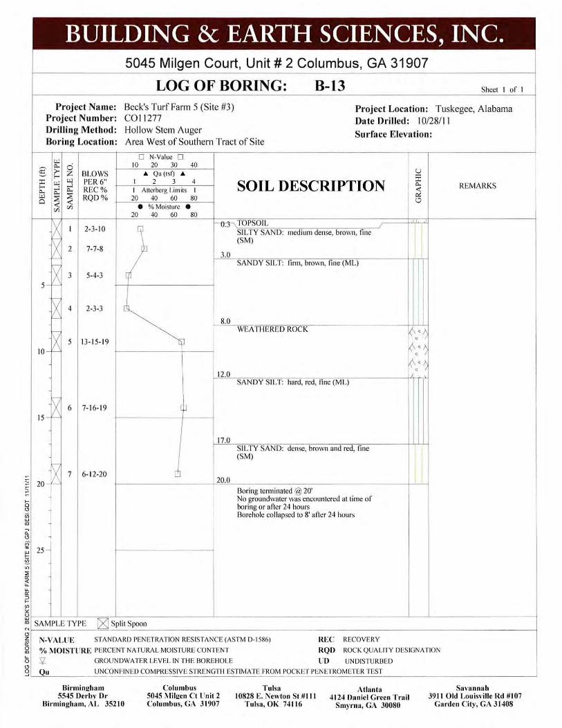
BUILDING & EARTH SCIENCES, INC. 5045 Milgen Court, Unit# 2 Columbus, GA 31907
LOG OF BORING: B-13 Sheet I of I
Project Name: Beck's Turf Farm 5 (Site #3) Project Number : C0 11 277
Project Location: Tuskegee, Alabama Da te Drilled: 10/28/ 11
Drilling Method: Holl ow Stem Auger Surface Elevation: Boring Location: Area West of Southern Tract of Site
u..l
g Q.. 0 >- z 13LOWS f-:r: u..l u..l PER6" f- ...)
...) REC% Q.. Q..
Q..
u..l ~ ~ RQD % Ci <t: <t: (/) (/)
~ I 2-3-10
IX 2 7-7-8 I-
~ 3 5-4-3 5 - ,___
X 4 2-3-3 '----'
X 5 13- 15-19 10 - '----'
r-; X 6 7- 16-19 15-'----'
...---; X 7 6- 12-20 ;; 20 - '----' ~
,__ 0 (!)
iii w m , 0.. (!)
~ ~ !!!. "' ~ <( u. u. a: ::;) ,__ (/) ;.:
25 -
[
Q
0 N-Value 0 10 20 30 40
"" Qu (tsf) "" I 2 3 4 I Atterberg Limits I 20 40 60 80
• % Moisture • 20 40 60 80
[\
ib
]
[p
c!J
SOIL DESCRIPTION
- 0:3\TOPSOIL
3.0
8.0
12.0
17.0
20.0
SILTY SAN D: medium dense, brown, fine (SM)
SANDY SILT: finn, brown, fine (ML)
WEt\ THERED ROCK
SANDY SILT: hard, red, fine (ML)
SILTY SAND: dense, brown and red, fine (SM)
Boring terminated @ 20' No groundwater was encountered at time of boring or afler 24 hours Borehole collapsed to 8' afler 24 hours
REMARKS
I
k\ ·~ ~ · ~ • 0 •l': •
~r-~_J--~---=~L-----------------~----------------------------------~---L------------------~ m SAMPLE TYPE ~ Spl i t Spoon Nf------------~=-------------------------------------------------------------------------------~
~ N-V ALliE STANDA RD PENETRATION RESISTANCE (ASTM D-1586) 0 m % MOIST URE PERCENT NATURAL MOISTURE CONTENT
~ 'Sj_ GROUNDWATER LEVEL IN THE BOREHOLE
REC RECOVERY
RQD ROCK QUALITY DESIGNATION
UD UNDISTURBED (!)
g Qu UNCONFINED COMPRESSIVE STRENGTH ESTIMATE FROM POCKET PENETROMETER TEST
Birmingham 5545 Derby Dr
Birmingham, AL 35210
Columbus 5045 i\llilgen Ct Unit 2 Columbus, GA 31907
Tulsa 10828 E. Newton St #Ill
Tulsa, OK 7411 6
Atlanta 4124 Daniel Green Trail
Smyma, GA 30080
Savannah 3911 Old Louisville Rd #107
Garden City, GA 31408