preparation checklist: grading and improvement plans
TRANSCRIPT

CITY OF SAN BUENAVENTURA PUBLIC WORKS DEPARTMENT LAND DEVELOPMENT DIVISION
PLAN CHECKLIST
PROJECT NO: _______________________________________ CITY DWG FILE NO. ____________
LOCATION: __________________________________________ OWNER: ______________________
ENGINEER: _________________________________________________________________________
Note: RETURN THIS CHECK LIST WITH YOUR REVISED PLANS.
Page 1 of 16 LAND_DEVELOPMENT_STANDARDS\Msword Format (Forms-New) Rev: 5/2015
Design Reference Documents (in order of preference): a. City of San Buenaventura Engineering Design Standards b. City of San Buenaventura Standard Construction Details c. Technical Guidance Manual for Stormwater Quality Control Measures d. County of Ventura Standard Design e. Standard Plans for Public Works Construction f. Standard Specifications for Public Works Construction NOTE: It is the responsibility of the Developer/Property Owner and/or the project Design Engineer to identify all modifications or revisions to the above standards, complete a “Design Deviation Request Form”, and submit for City acceptance prior to plan check submittal.
Legend:
√ Completed or Satisfactory N/A Not Applicable O Incomplete, revisions required FYI For Your Information
SUBMITTAL REQUIREMENTS - SEE PLAN CHECK SUBMITTAL REQUIREMENTS CHECKLIST
Description: 1st 2nd 3rd F
A. Approved phasing plan
B. Approved tentative map
C. Drainage study w/ hydrology/hydraulic calculations
D. Master Utility Plan
E. Conditions of approval (w/ resolution #)
F. Estimates of quantities and costs
G. Soils report & update letter
H. SWPCP or SWPPP (w/ NOI & WDID) and O&M Manual with Covenant
GENERAL (ALL SHEETS)
Description: 1st 2nd 3rd F
1. 24” x 36” x 3-MIL MYLAR DRAFTED IN INK OR PHOTO MYLAR WITH NO “STICKY-BACKS”, ZIP-A-TONE, ETC.
a. ½” Border top, bottom and right side
b. 1-1/2” border left side
2. LETTERING SIZE
a. CAD - 1/10 inch
b. Hand lettered – 1/8 inch
3. TITLE BLOCK
a. Project description, i.e. Tract No.; LD No.; PD No.; etc.
b. Description of improvements
4. CITY STANDARD SIGNATURE BLOCKS (SEE STD. DET. 407)
a. Parks Manager on Landscape Plans
b. Ventura Water General Manager on Utility Plans

2 of 16
LAND_DEVELOPMENT_STANDARDS\Msword Format (Forms-New) Rev: 5/2015
5. PREPARING ENGINEER’S SIGNATURE BLOCK
a. Name, address, phone number
b. Registration # and exp. date
c. Signature and date
d. Engineer’s seal
6. REVISION BLOCK
a. Revision #
b. Description
c. Approved by and date
7. CITY DRAWING FILE NUMBERS (lower right hand corner)
8. SID #
9. SHEET NUMBERS (lower right hand corner)
10. NORTH ARROW - to top or right
11. SCALES: 1” = 40’ or larger (locate w/ north arrow)
a. Numeric
b. Graphic
ALL COVER SHEETS
Description: 1st 2nd 3rd F
1. VICINITY MAP
a. Adjacent Streets
b. Major streets and highways within one mile of project
2. GENERAL NOTES (use city standard notes)
3. PERMIT NUMBERS (as applicable)
a. Grading
b. Encroachment
c. Ventura County Watershed Protection District
d. CALTRANS
e. CAL-OSHA
f. Others
4. BENCHMARK DATA
5. LIST OF ALL CITY STANDARD CONSTRUCTION DETAILS AND OTHER STANDARD CONSTRUCTION DETAILS
6. REFERENCE DRAWING NUMBERS
7. SHEET INDEX (See city standard construction detail 409)
8. INDEX MAP
9. LEGEND, ABBREVIATIONS, SYMBOLS
10. EARTHWORK QUANTITIES (grading plans only)
11. SOILS ENGINEER / GEOLOGIST SIGNATURE BLOCKS (grading plans only)
a. Names
b. Registration # and expiration dates
c. Signatures (original)
d. Seals (original)
e. List of soils reports with dates
3 of 16
LAND_DEVELOPMENT_STANDARDS\Msword Format (Forms-New) Rev: 5/2015
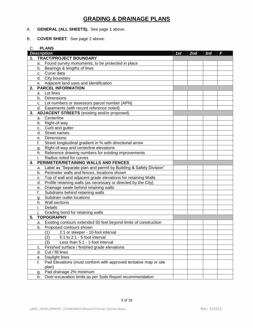
GRADING & DRAINAGE PLANS
A. GENERAL (ALL SHEETS). See page 1 above. B. COVER SHEET. See page 2 above.
C. PLANS
Description: 1st 2nd 3rd F
1. TRACT/PROJECT BOUNDARY
a. Found survey monuments, to be protected in place
b. Bearings & lengths of lines
c. Curve data
d. City boundary
e. Adjacent land uses and identification
2. PARCEL INFORMATION
a. Lot lines
b. Dimensions
c. Lot numbers or assessors parcel number (APN)
d. Easements (with record reference noted)
3. ADJACENT STREETS (existing and/or proposed)
a. Centerline
b. Right-of-way
c. Curb and gutter
d. Street names
e. Dimensions
f. Street longitudinal gradient in % with directional arrow
g. Right-of-way and centerline elevations
h. Reference drawing numbers for existing improvements
i. Radius noted for curves
4. PERIMETER/RETAINING WALLS AND FENCES
a. Label as “Separate plan and permit by Building & Safety Division”
b. Perimeter walls and fences, locations shown
c. Top of wall and adjacent grade elevations for retaining Walls
d. Profile retaining walls (as necessary or directed by the City)
e. Drainage swale behind retaining walls
f. Subdrains behind retaining walls
g. Subdrain outlet locations
h. Wall sections
i. Details
j. Grading bond for retaining walls
5. TOPOGRAPHY
a. Existing contours extended 50 feet beyond limits of construction
b. Proposed contours shown
(1) 2:1 or steeper - 10-foot interval
(2) 5:1 to 2:1 - 5-foot interval
(3) Less than 5:1 - 1-foot interval
c. Finished surface / finished grade elevations
d. Cut / fill lines
e. Daylight lines
f. Pad Elevations (must conform with approved tentative map or site plan)
g. Pad drainage 2% minimum
h. Over-excavation limits as per Soils Report recommendation
4 of 16
LAND_DEVELOPMENT_STANDARDS\Msword Format (Forms-New) Rev: 5/2015
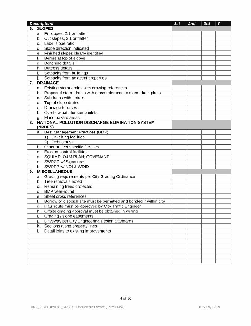
Description: 1st 2nd 3rd F
6. SLOPES
a. Fill slopes, 2:1 or flatter
b. Cut slopes, 2:1 or flatter
c. Label slope ratio
d. Slope direction indicated
e. Finished slopes clearly identified
f. Berms at top of slopes
g. Benching details
h. Buttress details
i. Setbacks from buildings
j. Setbacks from adjacent properties
7. DRAINAGE
a. Existing storm drains with drawing references
b. Proposed storm drains with cross reference to storm drain plans
c. Subdrains with details
d. Top of slope drains
e. Drainage terraces
f. Overflow path for sump inlets
g. Flood hazard areas
8. NATIONAL POLLUTION DISCHARGE ELIMINATION SYSTEM (NPDES)
a. Best Management Practices (BMP)
1) De-silting facilities
2) Debris basin
b. Other project-specific facilities
c. Erosion control facilities
d. SQUIMP, O&M PLAN; COVENANT
e. SWPCP w/ Signatures
f. SWPPP w/ NOI & WDID
9. MISCELLANEOUS
a. Grading requirements per City Grading Ordinance
b. Tree removals noted
c. Remaining trees protected
d. BMP year-round
e. Sheet cross references
f. Borrow or disposal site must be permitted and bonded if within city
g. Haul route must be approved by City Traffic Engineer
h. Offsite grading approval must be obtained in writing
i. Grading / slope easements
j. Driveway per City Engineering Design Standards
k. Sections along property lines
l. Detail joins to existing improvements

5 of 16
LAND_DEVELOPMENT_STANDARDS\Msword Format (Forms-New) Rev: 5/2015
STORM DRAIN PLANS A. GENERAL (ALL SHEETS). See page 1 above. B. COVER SHEET. See page 2 above.
1. C. PLAN VIEW
Description: 1st 2nd 3rd F
1. EXISTING IMPROVEMENTS SHOWN (w/ disposition noted)
a. Underground utilities / pipelines with size, type, and material
b. Pavement limits
c. Curbs and berms
d. County & State highways noted
e. City Drawing File Number references for existing improvements
f. Interfering structures
g. Manholes
2. PROPOSED STORM DRAIN
a. Size (minimum for public storm drain is 18 inches)
b. Type (i.e. pipe or box culvert)
c. Material (i.e. reinforced concrete within public R/W, w/ 1350-D load)
d. Horizontal alignment data
(1) Station / offset from street centerline, etc.
(2) Centerline curve data (delta, radius, length, tangent)
(3) Bearing (when needed)
e. Slope (when no profile shown)
3. OTHER PROPOSED IMPROVEMENTS
a. Street centerline
b. Street right-of-way
c. Curb & gutter
d. Pavement limits
e. Street names
f. Street dimensions
g. Lot lines adjacent to R/W
h. Lot numbers or APNs
i. Sewer main lines w/size & distance from storm drain (adequate clearance required)
j. Sewer laterals
k. Water main lines w/size & distance from storm drain (adequate clearance required)
l. Water services
4. CATCH BASINS
a. Location (w/ street stationing)
b. Type
c. Size
d. Local depression details (w/ street stationing)
5. INLET / OUTLET STRUCTURES
a. Location
b. Size
c. Type
d. Details
e. Grading
f. Headwall details
g. Energy dissipater

6 of 16
LAND_DEVELOPMENT_STANDARDS\Msword Format (Forms-New) Rev: 5/2015
Description: 1st 2nd 3rd F
6. MANHOLES
a. Location
(1) Junctions
(2) Bends
(3) Standard intervals
b. Type
c. Size
d. Deep manhole > 15’, 5’ diameter
7. TRANSITION / JUNCTION STRUCTURES
a. Location
b. Type
c. Size
d. Details
8. COLLARS
9. SUMP OVERFLOW PATH AND LIMITS
10. EASEMENTS
a. 15-foot-wide minimum and storm drain in the middle.
b. All on one side of lot line
c. Record reference noted
11. STATIONING
a. Increase from left to right across sheet (if possible)
b. Beginning of improvement
c. End of improvement
d. Match lines
e. BC and BVC
f. EC and EVC
g. Intersections
h. Structures
i. Catch basins
j. Changes of direction
k. Equations
12. CROSS REFERENCE SHEET NUMBERS
a. Other storm drain sheets
b. Grading plans
c. Street plans
d. Sewer plans
e. Water plans
13. CONSTRUCTION NOTES
D. NATIONAL POLLUTION DISCHARGE ELIMINATION SYSTEM (NPDES)
14. BEST MANAGEMENT PRACTICES (BMPs)
a. De-silting facilities
b. Debris basin
c. Other project specific facilities
15. EROSION CONTROL FACILITIES
16. STRUCTURAL BMPs
17. CONSISTENT WITH SWPCP/SWPPP

7 of 16
LAND_DEVELOPMENT_STANDARDS\Msword Format (Forms-New) Rev: 5/2015
E. PROFILE VIEW Description: 1st 2nd 3rd F
18. SCALES
19. Horizontal scale: 1” = 40’ (or larger)
20. Vertical scale 1 “ = 4’ (1” = 8’ on prior approval only)
21. Double vertical scale, noted boldly when approved
22. DATUM ELEVATIONS AT EACH END OF PROFILE
23. PROPOSED STORM DRAIN PROFILE
a. Existing ground over centerline of storm drain (for storm drain out of proposed streets)
b. Proposed finished surface over centerline of storm drain
c. Invert
d. Soffit
e. Adequate cover over storm drain
f. Grade / slope of pipe
g. Type (i.e. pipe or box)
h. Size
i. Length
j. Material (i.e. reinforced concrete)
k. Class / D-load and bedding load factor
l. Hydraulic grade line (HGL) delineated
m. Design flows (i.e. Q10 or Q50 or Q100)
n. Velocity
o. Manholes
p. Structures
q. Utility crossings {top of pipe (TOP), bottom of pipe (BOP) labeled}
24. STATIONING AND INVERT ELEVATIONS
a. 100 foot stations along bottom edge of profile
b. Beginning of improvement
c. End of improvement
d. Match lines
e. Manholes
f. Structures
g. Centerline of intersecting streets
h. Grade breaks
i. P.I.
j. Vertical curves
25. PIPE ANCHORS / BACKFILL STABILIZERS
26. INLET STRUCTURES
a. Top of curb / top of headwall elevation
b. Invert elevation
27. THICKENED CONCRETE OVER INVERT, (STEEL: 20 < V < 30, 1/2” thicker; 30< V< 40, 2” thicker)
28. VELOCITY DESSIPATOR (V>40 fps)

8 of 16
LAND_DEVELOPMENT_STANDARDS\Msword Format (Forms-New) Rev: 5/2015
SEWER PLANS A. GENERAL (ALL SHEETS). See page 1 above.
B. COVER SHEET. See page 2 above. C. PLAN VIEW
Description: 1st 2nd 3rd F
1. EXISTING (with disposition noted)
a. Underground utilities pipelines with size, type and material
b. Pavement limits
c. Curbs and berms
d. State & county highways noted
e. City drawing file number references for existing improvements
f. Interfering structures
g. Manholes
2. PROPOSED SEWER MAIN
a. Size - Minimum for public sewer is 8-inch
b. Material (PVC SDR-35 or VCP)
c. Horizontal alignment data
(1) Offset from street centerline, etc.
(2) Centerline curve data (delta, radius, length, tangent)
(3) Bearing (when needed)
d. Slope (when no profile shown)
3. PROPOSED SEWER LATERALS
a. Size
b. Material
c. Horizontal alignment data
(1) Stations along centerline
(2) Ties to lot lines at R/W
(3) Bearing (when needed)
d. Overflow / backflow devices
e. Gradient - 2% Minimum (when needed for clarification)
4. OTHER PROPOSED IMPROVEMENTS
a. Street centerline
b. Street right-of-way
c. Curb and gutter
d. Pavement limits
e. Street names
f. Dimensions
g. Lot lines adjacent to R/W
h. Lot numbers or APN
i. Lowest floor elevation containing plumbing fixtures
j. Water main lines and distance from sewer (adequate clearance req'd)
k. Water services
l. Storm drain main lines and distance from sewer (adequate clearance req'd)
m. Storm drain laterals

9 of 16
LAND_DEVELOPMENT_STANDARDS\Msword Format (Forms-New) Rev: 5/2015
Description: 1st 2nd 3rd F
5. MANHOLES
a. Location
(1) Junctions
(2) Bends
(3) Standard intervals (350-foot maximum)
b. Type
c. Size
d. Deep manhole > 15’, 5’ diameter
e. Coated with T-Lock
6. CLEANOUTS (Temporary on Public Sewer Line)
a. Location
b. Type
c. Size
d. Details
7. EASEMENTS
a. 15-foot wide minimum w/pipe in middle of easement
b. All on one side of lot line
c. Record reference noted
8. STATIONING
a. Increase from left to right across sheet (it possible)
b. Beginning of improvement
c. End of improvement
d. Match lines
e. BC and BVC
f. EC and EVC
g. Intersections
h. Manholes
i. Cleanouts
j. Changes of direction
k. Equations
9. CROSS REFERENCE SHEET NUMBERS
a. Other sewer sheets
b. Grading plans
c. Street plans
d. Water plans
e. Storm drain plans
10. DESIGN CONSIDERATIONS
a. Adequate clearance (horizontal)
11. CONSTRUCTION NOTES
12. SIGNATURE LINE FOR VENTURA WATER GENERAL MANAGER

10 of 16
LAND_DEVELOPMENT_STANDARDS\Msword Format (Forms-New) Rev: 5/2015
D. PROFILE
Description: 1st 2nd 3rd F
13. SCALES
a. Horizontal scale: 1” = 40’ (or larger)
b. Vertical scale 1“ = 4’ (1” = 8’ on prior approval only)
c. Double vertical scale noted boldly when approved
14. DATUM ELEVATIONS AT EACH END OF PROFILE
15. PROPOSED SEWER PROFILE
a. Existing ground over centerline of sewer (for sewer outside of proposed streets)
b. Proposed finished surface over centerline of sewer
c. Invert
d. Soffit
e. Adequate cover over pipe
f. Grade / slope of pipe
g. Size
h. Length
i. Material
j. Class / strength / load factor
k. Manholes
l. Cleanouts
m. Utility crossings
16. STATIONING AND INVERT ELEVATIONS
a. 100 foot stations along bottom edge of profile
b. Beginning of improvement
c. End of improvement
d. Match lines
e. Manholes (junctions 1/3 D)
f. Cleanouts
g. Centerline of intersecting streets
h. Grade breaks
i. P.I.
j. Vertical curves
17. PIPE ANCHORS I BACKFILL STABILIZERS

11 of 16
LAND_DEVELOPMENT_STANDARDS\Msword Format (Forms-New) Rev: 5/2015
WATER PLAN
A. GENERAL (ALL SHEETS). See page 1 above. B. COVER SHEET. See page 2 above. C. PLAN VIEW
Description: 1st 2nd 3rd F
1. EXISTING (With Disposition Noted)
a. Underground utilities / pipelines with size, type, and material
b. Pavement limits
c. Curbs and berms
d. State and county highways noted
e. City drawing file number references for existing improvements
f. Interfering structures
g. Fire hydrants
2. PROPOSED WATER MAINLINE
a. Size (8” minimum for public waterline)
b. Material
c. Horizontal alignment data
(1) Offset from street centerline
(2) Centerline curve data (delta, radius, length, tangent)
(3) Bearing and distances (when needed)
d. Pressure zone
e. Bedding noted
f. Water mainline looped
g. Minimum cover per city standards
3. PROPOSED WATER SERVICES
a. Size
b. Material
c. Horizontal alignment data
(1) Stations along centerline
(2) Ties to lot lines at R/W –typical details
(3) Bearing (when needed)
d. Domestic water meters with size
e. Landscape and Irrigation water meters with size
f. Backflow prevention device with screening
g. Pressure reducing valves with screening
4. OTHER PROPOSED IMPROVEMENTS
a. Street centerline
b. Street right-of-way
c. Curb and gutter
d. Pavement limits
e. Street names
f. Street dimensions
g. Lot Lines adjacent to R/W
h. Lot numbers
i. Sewer main lines
(1) Size
(2) Adequate distance from waterline (TOP & BOP)
j. Sewer laterals

12 of 16
LAND_DEVELOPMENT_STANDARDS\Msword Format (Forms-New) Rev: 5/2015
Description: 1st 2nd 3rd F
k. Storm drain main lines
(1) Size
(2) Adequate distance from waterline (TOP & BOP)
l. Storm drain laterals
5. WATER PLAN GENERAL NOTES (per City Std Construction Detail 001)
6. MISCELLANEOUS
a. Fire hydrants (locations approved by Fire Department)
b. Fire lines
c. Crosses with size
d. Tees with size
e. Thrust blocks shown & noted per City Std Construction Detail 006
f. Line valves with type and size
g. Vacuum and air release valves
h. Blow-offs
7. EASEMENTS
a. 15 ft wide minimum
b. All on one side of lot line
c. Record reference noted
8. 7. STATIONING
a. Increase from left to right across sheet (if possible)
b. Beginning of improvement
c. End of improvement
d. Match lines
e. BC
f. EC
g. Intersections
h. Fire hydrants
i. Services meters
j. Blow-offs
k. Vacuum and air release valves
l. Equations
9. CROSS REFERENCE SHEET NUMBERS
a. Other water sheets
b. Grading plans
c. Street plans
d. Sewer plans
e. Storm drain plans
10. CONSTRUCTION NOTES
D. PROFILE (10” or larger pipes)
Description: 1st 2nd 3rd F
11. SCALES
a. Horizontal scale: 1” = 40’ (or larger)
b. Vertical scale 1“ = 4’ (1” = 8’ on prior approval only)
c. Double vertical scale noted boldly when approved
12. DATUM ELEVATIONS AT EACH END OF PROFILE
13. ALL CROSSING REQUIRING OFFSETS SHOWN
14. SIGNATURE LINE FOR VENTURA WATER GENERAL MANAGER

13 of 16
LAND_DEVELOPMENT_STANDARDS\Msword Format (Forms-New) Rev: 5/2015
STREETS PLAN
A. GENERAL (ALL SHEETS). See page 1 above. B. COVER SHEET. See page 2 above. C. PLAN VIEW
Description: 1st 2nd 3rd F
1. EXISTING (with disposition noted)
a. Right-of-Way
b. Centerline
c. Easements
d. Utilities
e. Trees
f. Pavement (with elev.)
g. Curbs and berms (with elev.)
h. Signs and markers
i. Fences and walls.
j. Barricades and markers
k. Street lights
l. Traffic signals and appurtenances
m. Pipelines
n. State & county highways noted
o. Pole lines
p. Manholes
q. Storm drain inlets or structures
r. Street grades 100’ beyond end of proposed improvements
s. City drawing number references for existing improvements
2. PROPOSED
a. Centerline (labeled)
b. Right-of-way (labeled and Dimensioned)
c. Street names
d. Lot lines
e. Lot numbers or APN
f. Lot frontage dimensions
g. Tract / city boundary
h. Easements
i. Curve data on centerlines, right-of-way lines, curbs, (delta, radius, length and tangent)
j. Reference to city standard construction details
k. Other improvements in half tone
3. STATIONING
a. Increase from left to right across sheet (if possible)
b. Beginning of construction
c. End of construction
d. Match lines
e. Tract boundary
f. B.C.
g. E.C.
h. B.C.R.
i. E.C.R.
j. Centerline intersections
k. Centerline of Driveways

14 of 16
LAND_DEVELOPMENT_STANDARDS\Msword Format (Forms-New) Rev: 5/2015
Description: 1st 2nd 3rd F
l. Centerline of drainage devices
m. Transitions
n. Ends of local depressions
o. Street lights, signs, traffic control devices, etc.
4. TYPICAL STREET SECTIONS
a. Traffic index
b. Curb and gutter type
c. Centerline
d. Right-of-way width
e. Pavement width
f. Sidewalk width
g. Median width
h. Reference to City Standard Construction Details
i. Cross slope
j. Preliminary Structural Sections (min: local 3” A.C. on 6” A.B. arterial 4” AC. on 6” A.B.) State that actual structural section to be determined by soils analysis
5. CONCRETE STRUCTURES
a. Curb and gutter (type, flow line elev. and height))
b. Median islands
c. Cross gutters (when approved)
d. Sidewalk
e. Handicap ramps
f. Station for BCR and ECR
g. Transitions
h. Storm drain catch basins
i. Local depressions
j. Curb drains
k. Driveways (with width)
l. Joins (with elev.)
6. ASPHALT PAVEMENT
a. Limits
b. Overlay (indicate area by shading or other means)
c. Cold planning – limits and depth shown or noted
d. Transitions
e. Sawcut (min 1’) or at join with concrete
f. Joins (with elev.)
g. Berms
7. INTERSECTIONS
a. Curb return data (delta, radius, length and tangent)
b. Angle not less than 75 degrees nor greater than 105 degrees (90 degrees preferred)
c. Profile through intersection per Design Standards i. ii. iii. iv.
8. FIRE HYDRANTS
a. In conformance with Fire Department approval
b. Detail where in sidewalk (4’ min clear walk width)
9. PARKWAY TREES
10. WALLS / FENCES
a. Retaining walls require a separate permit by Building and Safety
b. Fences over 6’ high require a separate permit by Building and Safety

15 of 16
LAND_DEVELOPMENT_STANDARDS\Msword Format (Forms-New) Rev: 5/2015
Description: 1st 2nd 3rd F
11. DESIGN CONSIDERATIONS
a. Horizontal and vertical curve design and stopping sight distance shall be per City standards and State Highway Design Manual
b. Conformance with approved tentative map and conditions of approval
c. No undrained depressions
d. Modification of standards requires complete detail on plans
e. Future street extension show design feasibility for 100’ beyond end of proposed improvements
12. CONSTRUCTION NOTES
13. CROSS REFERENCE SHEET NUMBERS
a. 0ther street sheets
b. Grading plans
c. Sewer plans
d. Water plans
e. Storm drain plans
D. PROFILE
Description: 1st 2nd 3rd F
1. SCALES
a. Horizontal scale: 1” = 40’ (or larger)
b. Vertical scale: 1 “ =4’ (1” = 8’ on prior approval only)
c. Double vertical scale noted boldly when approved
2. DATUM ELEVATIONS AT EACH END OF PROFILE
a. Centerline
b. Top of curb left and right
3. EXISTING GROUND AT CENTERLINE
4. PROPOSED CENTERLINE PROFILE
5. TOP OF CURB BOTH LEFT AND RIGHT OF CENTERLINE
6. CURB RETURNS
a. BCR
b. ECR
c. ¼ Points on curb returns
d. Length of Curb returns
7. LABELS
a. Existing ground lines
b. Proposed profiles
c. % of grade
d. Vertical curves
8. STATIONING AND ELEVATIONS
a. 100 foot stations along bottom edge of profile
b. Beginning of Improvement
c. End of Improvement
d. P.I.
e. Vertical curves
f. Grade Breaks
g. Equations of curved streets
h. Match lines
9. JOINS TO EXISTING IMPROVEMENTS
a. Beyond end of improvement a minimum of 100’ for existing and/or future improvements
b. Existing elevations
10. DRAINAGE (Show graded or improved drainage facilities)

16 of 16
LAND_DEVELOPMENT_STANDARDS\Msword Format (Forms-New) Rev: 5/2015
E. STREET LIGHTING, SIGNING AND STRIPPING PLAN
Description: 1st 2nd 3rd F
11. SIGNATURE BLOCK FOR CITY TRAFFIC ENGINEER
12. STREET NAME SIGNS
a. Location
b. Reference to city standards
13. REGULATORY SIGNS
a. Type
b. Reference to city standard
c. Size
d. Location
14. STREET LIGHTS
a. Type
b. Size
c. Location v. vi. vii. viii.
15. STRIPING AND PAVEMENT MARKERS
a. Location
b. Type
c. Details
16. BARRICADE
a. At dead end streets
Note: RETURN THIS CHECK LIST WITH YOUR REVISED PLANS.