presentation of power generation
TRANSCRIPT

POWER GENERATION FROM SPEED BREAKERS
Group Members:
Muhammad Farukh 12-EE (P)-52
Muhamamd Waqas Iqbal12-EE (P)-68
Saqib Rehman 12-EE (P)-79
Taimoor Ashraf 12-EE (P)-084

CONTENTS Introduction Different mechanisms Spring coil mechanism Roller mechanism Rack pinion mechanism Different Comparisons Merits and Demerit Scope and Uses Conclusion References

INTRODUCTION A large amount of energy is wasted at the speed
breakers through friction , every time a vehicle passes over it.
So electricity can be generated using the vehicle weight and speed (kinetic energy) as input.
So, this is a small step to try to improve this situation.

POSSIBLE USING DIFFERENT MECHANISMS
SPRING COIL MECHANISM
ROLLER MECHANISM CRANK-SHAFT MECHANISM
RACK- PINION MECHANISM

CONSTRUCTION OF THE SPEED BREAKER Here we are making the speed breaker of vibrating
type, when a vehicle crosses the speed breaker, it gets pressed and then it gets back to its original position.
Dimensions of speed breaker:- Height : 0.2m Width : 0.4m Length : 4mo The material used in construction of speed breakers is
steel.
o The shape of speed breaker is trapezoidal .

CONSTRUCTION OF THE TRENCH• Height: 0.35m• Length : 4m• Width :0.45m• The bottom layer of the trench is filled with concrete or with wooden plates of 0.5m. •This is for cushion effect.
DESIGN OF THE SPRING The actual height of spring is 0.3m before loading. The deflection of the spring is given by δ = 64 w *n*N*R^3 /(G^4) where δ-deflection (in our case maximum δ =0.1m) w=designed load R= mean diameter of coil n=no of spring turns G= Modulus of rigidity = 8*10^4 N/m^2 N= No. of springs The no of turns in the spring to get the deflection
of 0.1m is given by n= (0.1)G^4/(64 w*N*R^3)

WORKING PROCESS Maximum load on the speed
breaker is when the vehicle is on the middle of the speed breaker.
When the pressure in the FRL unit exceeds the defined level the valve opens and the pressurized air is given to the nozzle.
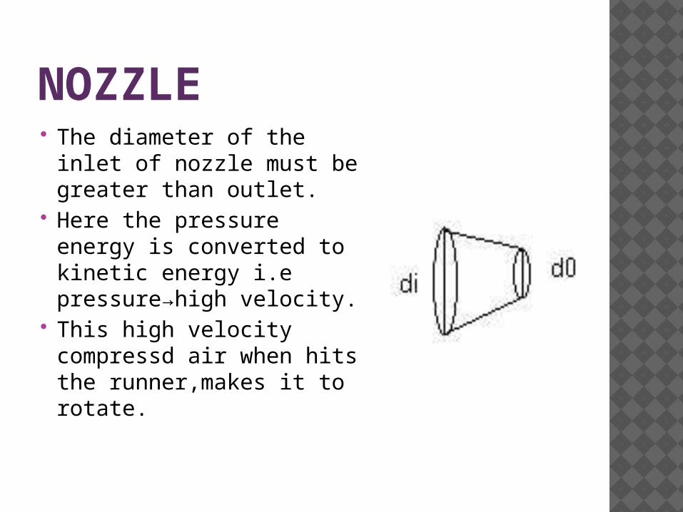
NOZZLE The diameter of the inlet
of nozzle must be greater than outlet.
Here the pressure energy is converted to kinetic energy i.e pressure→high velocity.
This high velocity compressd air when hits the runner,makes it to rotate.

RUNNER It consists of a circular
disc on the periphery of which have number of buckets evenly spaced are fixed. Each bucket is divided in to 2 symmetrical parts by a dividing wall is know as splitter.
When the air strikes the runner ,it rotates & continues rotation due to inertia.

ROLLER MECHANISM Here roller ,sprocket-chain arrangement is used. Ratio of speed of roller to dynamo shaft is 1:4.

MECHANISM OF DIFFERENT PARTS Sprocket mechanism Transfers rotary motion between two shafts
Dynamo It is the dc generator which is use to generate current Generates current as per the Faraday’s Law

BLOCK DIAGRAM1
• Speed Breaker Arrangement
2• Roller Arrangement
3• Sprocket Drives
4• Chain Drive
5• Dynamo shaft
6• Battery
RACK-PINION MECHANISM
The various machine elements used in the construction of power hump are
RACK-PINION
SPROCKETS
GEARS FLY WHEEL
Dynamo
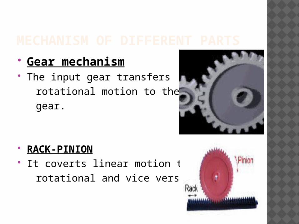
MECHANISM OF DIFFERENT PARTS Gear mechanism The input gear transfers rotational motion to the output gear.
RACK-PINION It coverts linear motion to rotational and vice versa.
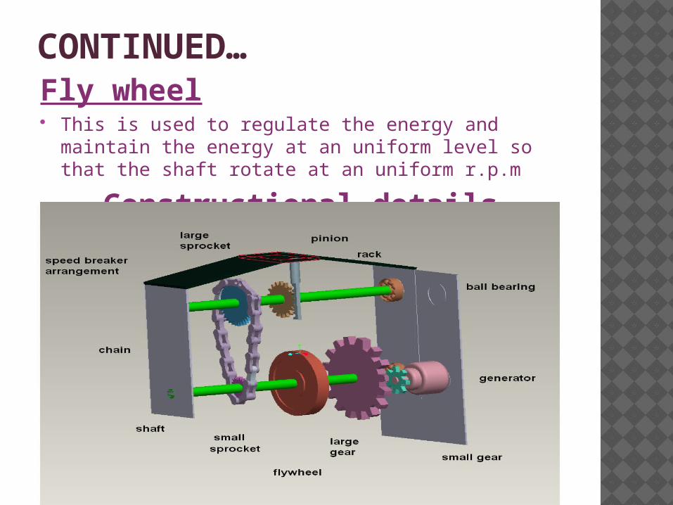
CONTINUED…Fly wheel This is used to regulate the energy and maintain the energy at an
uniform level so that the shaft rotate at an uniform r.p.m
Constructional details
WORKING PROCEDURE Here the reciprocating motion of the speed-breaker is converted
into rotary motion using the rack and pinion arrangement.
Rack and pinion gears normally change rotary motion into linear motion, but sometimes we use them to change linear motion into rotary motion.
The axis of the pinion is coupled with the sprocket arrangement.
The axis of the smaller sprocket is coupled to a gear arrangement.
Finally the gear arrangement is coupled with the generator

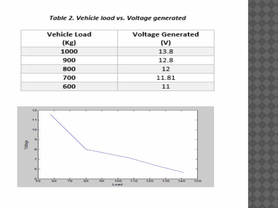
CALCULATIONS & RESULTS: Average Weight of a Vehicle = 700Kg Height of speed brake =10 cm Work done=Force x Displacement W=F.d cos (ϴ) > ϴ= 0°, because force acted in the direction of
displacement. Force= mass x gravitational force Force=700 Kg x 9.81 =6867 N Displacement covered by the speed breaker= 10cm /0.10 m Output power=Work done/Sec Output power= (6867 x 0.10)/60 Output power= 11.445 Watts Power developed for 1 vehicle passing over the speed breaker is 11.445
watts; due to flywheel it delivers power for one minute continuously. So the Power developed for:
1 hr =686.7 watts 24 hours=16.480 KW
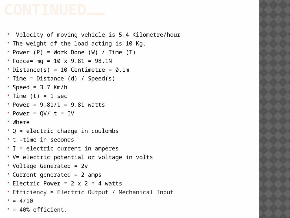
CONTINUED…… Velocity of moving vehicle is 5.4 Kilometre/hour The weight of the load acting is 10 Kg. Power (P) = Work Done (W) / Time (T) Force= mg = 10 x 9.81 = 98.1N Distance(s) = 10 Centimetre = 0.1m Time = Distance (d) / Speed(s) Speed = 3.7 Km/h Time (t) = 1 sec Power = 9.81/1 = 9.81 watts Power = QV/ t = IV Where Q = electric charge in coulombs t =time in seconds I = electric current in amperes V= electric potential or voltage in volts Voltage Generated = 2v Current generated = 2 amps Electric Power = 2 x 2 = 4 watts Efficiency = Electric Output / Mechanical Input = 4/10 = 40% efficient.

FOR SMALL MASS VEHICLES:
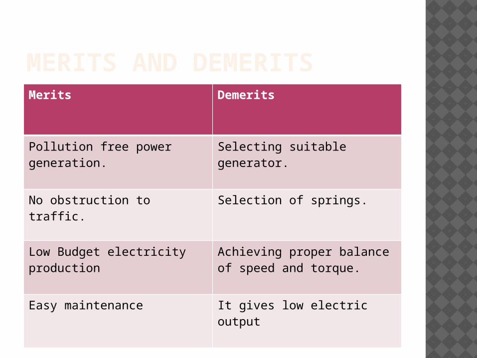
MERITS AND DEMERITSMerits Demerits
Pollution free power generation.
Selecting suitable generator.
No obstruction to traffic. Selection of springs.
Low Budget electricity production
Achieving proper balance of speed and torque.
Easy maintenance
It gives low electric output

SCOPE AND USES This mechanism is very economical and
easy to install. Two protocols of this type of speed breakers
are developed in India .not practically implemented till date.
Practically implemented in New Jersey , China and Indonesia.
Lots of researches and investigations are going on to practically utilize this technique
By doing proper arrangements we may generate high power electricity

CONCLUSION The existing source of energy such as coal, oil etc
may not be adequate to meet the ever increasing energy demands. These conventional sources of energy are also depleting and may be exhausted.
These are some non-conventional methods of producing energy. This is a one step to path of exploring the possibilities of energy from several non-conventional energy sources.

REFERENCES C. K.Das1,S. M.Hossain2,M. S.Hossan3 "Introducing Speed Breaker
as a Power Generation Unit for Minor Needs"Informatics, Electronics & Vision (ICIEV), 2013 International Conference on 17-18 May 2013.
ASWATHAMAN.V,PRIYADHARSHINI.M"EVERY SPEED BREAKER IS NOW A SOURCE OF POWER",2010 International Conference on Biology, Environment and Chemistry IPCBEE vol.1 (2011) © (2011) IACSIT Press, Singapore.
Alok Kumar Singh,Deepak Singh,Madhawendra Kumar,Vijay Pandit,Prof.SurendraAgrawal "Generation of Electricity through Speed Breaker Mechanism"International journal of innovations in Engineering and Technology(IJIET) volume issue 2 April 2013.
Parul Bisht,Rajni Rawat,"Electricity Generation through Road Ribs using law of Electromagnetic Induction" Conference on Advances in Communication and Control Systems 2013 (CAC2S 2013)

THANK YOU