pressure-based electronic line leak detector system · system sentinel™ and system sentinel ™...
TRANSCRIPT

Part Number: 000-0140 Rev. CCopyright © March 2008
User’s Guide
TS-LS300 Auto-Learn®
Pressure-Based Electronic Line Leak Detector
System

INSIDE FRONT COVERLS300 User’s Guide
NOTICE
INCON has strived to produce the finest possible manual for you, and to ensurethat the information contained in it is complete and accurate. However, INCONmakes no expressed or implied warranty with regard to its contents. INCONassumes no liability for errors or omissions, or for any damages, direct orconsequential, that result from the use of this document or the equipment which itdescribes.
This document contains proprietary information and is protected by copyright. Allrights are reserved. No part of this document may be reproduced in any formwithout the prior written consent of INCON.
INCON reserves the right to change this document at any time without notice.
Need Help ? Mail Address (no packages):INTELLIGENT CONTROLS INCPO BOX 638SACO ME 04072
Office Hours: 8 am to 5 pm EST, Monday through Friday
Sales – Orders 24 hour Technical ServiceDelivery Schedules: RMA, Application Help:
Fax: (207) 283-0158 Fax: (207) 282-9002Phone: (800) 872-3455 Phone: (800) 984-6266email: [email protected] email: [email protected]
INCON is a wholly owned subsidiary of Franklin Electric and is member of the:Franklin Fueling Systems Group. Visit our web site at:
Tank Sentinel® BriteSensors® and INCON® are registered trademarks of Intelligent Controls, Inc.System Sentinel™ and System Sentinel ™ are trademarks of Intelligent Controls, Inc.LS300 Auto-Learn® is a registered trademark of FE Petro®.
Copyright© 2003 – all rights reserved.
www.franklinfueling.com

TABLE OF CONTENT Page TOC-1 TOCLS300 User’s Guide
Table of Contents
Preface ............................................................................................................ P-1
Safety ............................................................................................................... 1-1
Mechanical Installation..................................................................................... 2-1
Electrical Installation & Wiring ......................................................................... 3-1
Line Calibration ................................................................................................ 4-1
LS300 Console Operation ............................................................................... 5-1
TS-LS300 Troubleshooting guide .................................................................... 6-1
Appendix A Specifications ................................................................................. A-1

PREFACE Page P-1 PLS300 User’s Guide
P Preface
— Important – ReadRead and follow the entire instructions in this manual before installing or working on this equipment.
Certified Installer/Service Person: Only an INCON certified installer or service person is allowedto access both the user interface kepad and areas internal to the TS-LS300 console.
Station Owner/Operator: The station owner or operator of the TS-LS300 console is only allowed toaccess the user interface keypad. Access to areas internal to the console is strictly prohibited.
Graphic Symbol Conventions
Important information, tips, and hints are highlighted by the note graphic.
CAUTION messages are highlighted by the CAUTION graphic and contain instructions that shouldbe followed to avoid faulty equipment operation, or environmental hazards, or personnel injury!
WARNING messages are highlighted by the WARNING graphic and contain instructions thatmust be followed to avoid faulty equipment operation or explosion. If ignored, severe injury or deathmay result!
DANGER messages are highlighted by the DANGER graphic and contain instructions that mustbe followed to avoid an explosion or fire hazard. If ignored, severe injury or death will result!
ELECTRICAL DANGER messages are highlighted by the ELECTRICAL DANGER graphic andcontain instructions that must be followed to avoid an electrical shock. If ignored, severe injury ordeath may result and even severe damage to electronic equipment.
NOTE
NOTE
Earth Ground Terminal
Ground Terminal
Alarm/Failed Test
Testing/Passed Test
Pressure Low/Pump OFF
Pressure High/Pump ON
Horn/Audible Alarm
Test/Reset
Single Phase AlternatingCurrent
A
T
orH

P Page P-2 PREFACELS300 User’s Guide
General OverviewThe TS-LS300 Auto-Learn® Line Leak Detector (LLD) is a precision electronic line-leak-detectionsystem that is produced for installation in a petroleum pumping system. The Auto-Learn Line LeakDetector automatically monitors at certain times and will indicate pipeline leaks should a leak occur.An alarm indicator lights, an audible alarm horn sounds, and positive pump shutdown happens whena leak is detected. This complies with U.S. EPA requirements 280.41(b) & 280.44(a) for automaticleak detection in pressurized piping. After installation, the user of the leak detector must monitor thesystem to ensure that any leak alarm and pump shutdown (indicating a leak in the pipeline) is dealtwith promptly.
The Auto-Learn LLD can detect a leak from the STP check valve to the solenoid valve at thedispenser, assuming no other Normally Closed valve is in the pipeline system. The Auto-Learn LLDdoes not detect leaks from the fuel storage tank or the from the submersible pump before the outputcheck valve. The Auto-Learn LLD is used with motor fuels.
The system includes a 2 or 4 channel LSU300 console with stick-on Product ID Labels, DangerLabels, one Auto-Learn Calibration Kit (leak-generator), 2 to 4 Needle Valve Kits, no-spliceconnectors, and 2 to 4 LSU300 pressure-transducers as specified at time of order. Each channel willmonitor one piping system or product line. All line leak detectors must be tested upon start-up, androutinely thereafter (at least annually) under NFPA standards. These NFPA and other industrytesting practices must be followed by the installer and the end user. A leak detector is not asubstitute for compliance with prudent industry practices. Fuel inventory reconciliation checks mustbe performed on a daily basis by comparing dispenser meter totalizers with fuel volume changes inthe underground tank.
The Auto-Learn LLD pressure transducer is manufactured in two different versions:
1) The TS-LSU300 pressure transducers are Intrinsically Safe (I.S.) for U.S. andinternational markets and are for use only with the TS-LS300 version console
2) The TS-LSU300E pressure transducers are Explosion Proof for Canadian andU.S. markets and are for use only with the TS-LS300E version console
Wire Intrinsically Safe LSU300 transducers only with TS-LS300 consoles... physicalseparation of transducer cables from non-intrinsically safe circuits is also required.
Wire Explosion Proof LSU300E transducers only with TS-LS300E consoles in accordancewith applicable standards... use of explosion proof J-Boxes and conduit fittings in hazardouslocations. This wiring does not require separation from other non-intrinsically safe circuit wiring. Thismethod can be used for retrofit installations where separate conduit is not available.
This Installation and Owner’s Manual gives instructions for, site assessment and preparations,installation, wiring, calibration, and operation. Each section gives step by step process tosuccessfully complete the section. A troubleshooting guide is included if difficulties are encountered.
NOTE

PREFACE Page P-3 PLS300 User’s Guide
Each product line must be precision tested and verified free of leaks before any component of theLS300 system is installed. After verification, the LS300 Auto-Learn® system is installed, wired, andcalibrated. The supplied leak-generating device/calibration kit* is attached to a needle valve, and theappropriate line channel selector switch is placed in the learn position at the console. Each line iscalibrated separately, one at a time, to “learn” the parameters and characteristics of a line with aknown induced leak-rate.
At each STP housing, the needle valve kits* are assembled and installed in the pressure test ports,and the LSU300 pressure-transducers are installed in 2 inch NPT line leak detector ports (LSU300cable length must not exceed 500 feet).
After a line is calibrated the leak-generator device is moved to the next product line for Auto-Learncalibration. The entire process is repeated until all lines are separately calibrated and the console isleft in the Run – Detect mode.
The front panel has a power on light and 4 status-lights per line. The status lights show currentlyrunning line leak tests, faults, and alarms. Fault-alarms will cause indicator lights to blink or flash.Certain alarms will also activate the internal alarm horn. Manual line leak tests may be started and
Figure P-1 LS300 LLD System Components
2 CHNL LS300
* The needle valve kit and the leak generating device/calibration kit have not beenevaluated by Underwriters Laboratories.
LEAK GENERATINGDEVICE
NEEDLEVALVE
LSU300 TRANSDUCER
# 3 with3 / 4 Chnl
# 4 with4 Chnl
PRODUCTID
STICK-ONDANGER
3 OR 4 CHNL
NO-STRIPSPLICE
2 CHNL

P Page P-4 PREFACELS300 User’s Guide
the alarm horn can be silenced by pressing the Test/Reset push-button on the appropriate channel,which will silence the alarm horn and can start a new manual Line Leak Test.
The LS300 System Applications – 5 block diagramsThe block diagrams on the next page, Figure P-1, show the 5 different applications possible with thisequipment. Only block diagram #1, Basic Auto-Learn electronic Line Leak Detector (LLD) console,
is covered in this manual, See TS-TPI, TS-1001-, TS-2001, or STP controller User guides for moreinformation on the other applications. The possible Applications are:
# 1 Basic Auto-Learn electronic Line Leak Detector (LLD) console
# 2 One LS300 Auto-Learn console with TS-TPI plus an INCON ATG (Automatic TankGauge) console for LLD interface
Note: TPC is the designation for a Turbine Pump Controller throughout thismanual
# 3 One LS300 Auto-Learn console with TS-TPI for Turbine Pump Controller (TPC)interface and an INCON ATG console for LLD and Pump Controller interface
# 4 Two LS300 Auto-Learn consoles for support of up to 8 lines: one console has theTS-TPI interface circuit board enabling connection to the other LS300 console via aspecial RS-232 cable and to the INCON ATG console via RS-485 communicationfor LLD interface
# 5 Two LS300 Auto-Learn consoles for line leak detection of up to 8 lines: one consolehas the TS-TPI interface circuit board for connection to the other LS300 console viaa special RS-232 cable and connects to the INCON ATG console via RS-485communication for LLD interface and for Turbine Pump Controller control
TABLE P-1 Console Channel X - Test/Reset PB
See theOperationsection in thismanual or theQuickReferenceGuide
Push#
TimesEffect
1 Silences Alarm Horn
2 Gross (3 gph / 11 Lph) Line Leak Test
3 Monthly (0.2 gph / 0.8 Lph) Line Leak Test
4 Annual (0.1 gph / 0.4 Lph) Line Leak Test

PREFACE Page P-5 PLS300 User’s Guide
Site Survey & AssessmentA precision line test must be conducted before installing the LSU300 transducer forthe first time and before replacing any line leak detector that is indicating a leak toassure line integrity .
Before installation of Auto-Learn system verify that the equipment is proper for thesite.
Check that the pipeline volume (based on length, internal diameter, and pipe type)is less than the 3rd party approval (see Table P-2). Third party tests have approved
Figure P-1 Auto-Learn System Applications (5) – Block Diagram
LLDRS485
Inputs (#1-4):Lines (#)
Power
Hooks (#)
Power
Hooks (#)
Inputs (#1-4):Lines (#)
Inputs (#1-4):
4
TS-ATGConsole
5TPC TPC TPC
LLDRS485
LLDRS485
TS-LS300Auto-LearnConsole #1
WITHTS-TPIPCB
TS-TPIPCB
TS-ATGConsole
1
TS-LS300Auto-Learn
Console
TS-ATGConsole
3
TS-LS300Auto-Learn
Console
LLDRS485
TPC TPC
TS-LS300Auto-LearnConsole #1
TS-TPIPCB
Inputs (#1-4):Lines (#)
Hooks (#)
Power 2
TS-ATGConsole
Lines (#)
TPCTPC TPC TPC TPC
TS-LS300Auto-LearnConsole #2
Inputs (#5-8):
Hooks (#)
Lines (#)
Power
Hooks (#)
Power
TS-LS300Auto-LearnConsole #2
TPC TPC
Hooks (#)
Lines (#)
Power
Inputs (#5-8):
TS-TPIPCB
TS-LS300Auto-Learn
ConsoleInputs (#1-4):
Lines (#)
Power
Hooks (#)
P Page P-6 PREFACELS300 User’s Guide
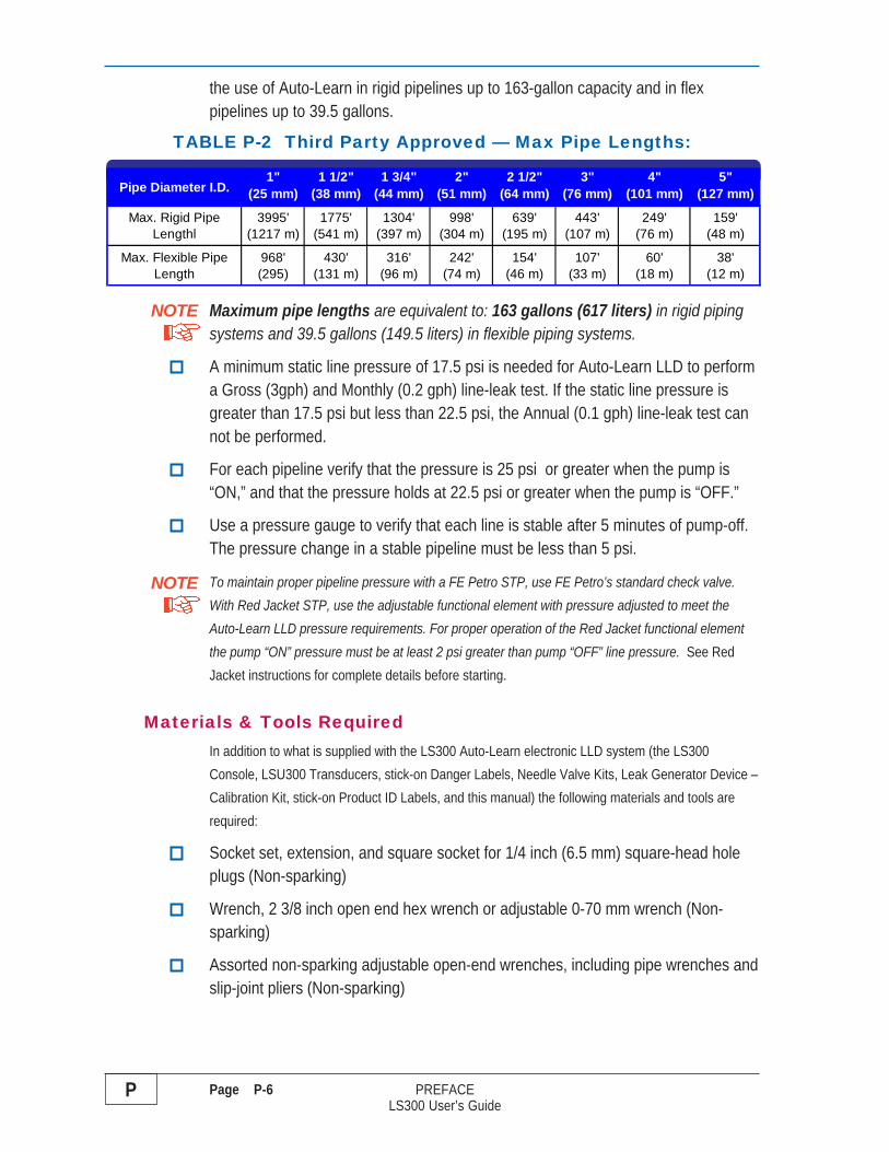
the use of Auto-Learn in rigid pipelines up to 163-gallon capacity and in flexpipelines up to 39.5 gallons.
TABLE P-2 Third Party Approved — Max Pipe Lengths:
Maximum pipe lengths are equivalent to: 163 gallons (617 liters) in rigid pipingsystems and 39.5 gallons (149.5 liters) in flexible piping systems.
A minimum static line pressure of 17.5 psi is needed for Auto-Learn LLD to performa Gross (3gph) and Monthly (0.2 gph) line-leak test. If the static line pressure isgreater than 17.5 psi but less than 22.5 psi, the Annual (0.1 gph) line-leak test cannot be performed.
For each pipeline verify that the pressure is 25 psi or greater when the pump is“ON,” and that the pressure holds at 22.5 psi or greater when the pump is “OFF.”
Use a pressure gauge to verify that each line is stable after 5 minutes of pump-off.The pressure change in a stable pipeline must be less than 5 psi.
To maintain proper pipeline pressure with a FE Petro STP, use FE Petro’s standard check valve.With Red Jacket STP, use the adjustable functional element with pressure adjusted to meet theAuto-Learn LLD pressure requirements. For proper operation of the Red Jacket functional elementthe pump “ON” pressure must be at least 2 psi greater than pump “OFF” line pressure. See RedJacket instructions for complete details before starting.
Materials & Tools RequiredIn addition to what is supplied with the LS300 Auto-Learn electronic LLD system (the LS300Console, LSU300 Transducers, stick-on Danger Labels, Needle Valve Kits, Leak Generator Device –Calibration Kit, stick-on Product ID Labels, and this manual) the following materials and tools arerequired:
Socket set, extension, and square socket for 1/4 inch (6.5 mm) square-head holeplugs (Non-sparking)
Wrench, 2 3/8 inch open end hex wrench or adjustable 0-70 mm wrench (Non-sparking)
Assorted non-sparking adjustable open-end wrenches, including pipe wrenches andslip-joint pliers (Non-sparking)
NOTE
NOTE
Pipe Diameter I.D.1"
(25 mm)1 1/2"
(38 mm)1 3/4"
(44 mm)2"
(51 mm)2 1/2"
(64 mm)3"
(76 mm)4"
(101 mm)5"
(127 mm)
Max. Rigid Pipe Lengthl
3995'(1217 m)
1775'(541 m)
1304'(397 m)
998'(304 m)
639'(195 m)
443'(107 m)
249'(76 m)
159'(48 m)
Max. Flexible Pipe Length
968'(295)
430'(131 m)
316'(96 m)
242'(74 m)
154' (46 m)
107'(33 m)
60'(18 m)
38'(12 m)

PREFACE Page P-7 PLS300 User’s Guide
Petroleum absorbent and absorbent rags, and approved waste containers
Gasoline/oil resistant, non-hardening, UL Classified, Teflon Pipe Dope / ThreadSealant (Gasoila) to seal threads of the LSU300 transducer & Needle Valve Kit
Single scale, general purpose, Pressure Gauge (1/4 inch NPT, 0 to 60 psi in 1 psiincrements) for temporary installation during site assessment and during theLS300 Auto-Learn calibration step
Approved Gasoline/fuel oil container test tank (minimum 5-gallon capacity) tocollect product from the leak generator calibration kit during Auto-Learn calibration
Level, measuring tape, scribes/punch, and fasteners for wall mounting of console
Threaded 3/4 inch NPT (DN20NPT) rigid metal conduit, conduit bender, conduitcutter, couplings, fittings, plus Epoxy Y Seal fittings (EYS), quick set epoxy, andConduit Clamps/Hangers
Explosion / Weather Proof J-Boxes
LSU300 Transducer Cable: Belden shielded cable #9363-22AWG,#9364-20AWG, or #9365-18AWG or equivalent (#9365-18AWG is preferred)
RS-485 Cable – for ATG and Pump Controllers – use the Transducer Cable above#9365-18AWG preferred. Shield wire is connected to RS-485 “Ground” terminal onthe TPI board (The other end of the sheild is not connected).
Wire for LS300 Auto-Learn LLD console: Power Input and Hook Inputs — per code
Electricians tools (Safety Lockouts &Tags, assorted wire strippers, cutters, varioussize – flathead and phillips-head screwdrivers, multimeter with leads & clips, strain-relief fittings, spanner wrenches, slip-joint pliers [Non-sparking] conductor markers,and indelible fine point marking pens)

SAFETY Page 1-1 1LS300 User’s Guide
1 SAFETY
Safety First – Before Working on this Equipment
CAUTION This equipment is designed to be installed in association with volatilehydrocarbon liquids such as gasoline and diesel fuel. Installing or working on this equipmentmeans working in an environment in which these highly flammable liquids or vapors arepresent. This presents a real risk of severe injury or death if these instructions and standardindustry practices are not followed.
Prohibit access to the work area to certified and trained installers/service personnel
Identify and mark the perimeter of the work area with signs, safety-cones and colored safety tape
Prevent unauthorized vehicle access (block access) into the work areas by using barriers,barricades, and service trucks
Use only non-sparking tools when working in these Hazardous Areas
Occasionally check for presence of hydrocarbon vapors in containment sumps
ELECTRICAL DANGER Lethal Electrical Shock Hazard! Before installing, servicing, orworking on this equipment: turn off all submersible pump power / pump controller power, TankSentinel console power, LS300 electronic Line Leak Detector console power, and dispenser powerat the electrical power panel(s). Lock out and tag these circuit breakers in the off position to preventaccidental / unauthorized circuit breaker closure. Failure to turn off and lock out power would resultin severe injury or death!
WARNING Highly flammable vapors may be present in the environment where this equipment isinstalled or serviced. DO NOT smoke while working on or near this equipment and only use non-sparking tools. Failure to follow this instruction could result in a serious fire or explosion.
WARNING Follow all federal, state, and local laws governing the installation of thisproduct and the entire system. When no other regulations apply, follow NFPA 30, 30A, and 70from the National Fire Protection Association. Failure to do so could result in seriousproperty damage, environmental-contamination, and severe injury or death.
ELECTRICAL DANGER Verify that no voltage exists before working-on, or wiring-to circuitsdescribed in this manual, otherwise lethal electrical-shock-hazards could exist, which may causeinjury or death. Note: circuit breaker contact(s) can fail to open even when the circuit breaker leverindicates off.

1 Page 1-2 SAFETYLS300 User’s Guide
ELECTRICAL DANGER Electronic line leak detectors start submersible pumpsautomatically to run leak-tests at full line pressure. Automatic pump starts occur betweenperiods of product dispensing when there is no product being dispensed. Before performingany installation or service (such as replacing fuel-filters) – tag and lock-out all electrical powersources to the submersible pump(s), pump controllers, and dispensers and relieve fuel-line pressure.Failure to turn off power and relieve fuel-line pressure before work is started can result in:pressurized fuel spills (an environmental hazard associated with costly clean-ups), and fire orexplosion hazard that may result in injury or death.
Multiple INCON Danger stickers are supplied with electronic lineleak detectors. Apply these stickers on the pump relay boxcover, in locations near dispenser fuel-line filters, plugs,emergency safety-shut-off valves, on or near the Leak SensingUnit Transducer (at the submersible pump housing), and otherserviceable components of a fuel line (where a spill wouldoccur if the line became pressurized). The selected surfacesmust be clean, dry, and in plain sight so that the label can beread, and followed.
WARNING The fuel line from the submersible pump to the dispenser, may be underpressure. Turn off all pump power and relieve pipeline pressure (reference and follow thepump manufacturer’s directions about how to do this). If the line leak detector/plug (or anyother part of the submersible pump and fuel line) is removed without first relieving pressure,then a product leak will occur. This could cause an environmental, fire, or explosion hazard,and may result in injury or death.
WARNING Avoid personnel injury or property damage: keep moving vehicles andunauthorized personnel out of the hazardous work area. Use Safety Cones, Barricades,Warning Signs, and Safety Tape, and block access with Barricades / service trucks to thework area to avoid injury or property damage.
WARNING Be careful not to cause sparks when working on fuel dispensing equipment(volatile fuel may be within the pump’s leak detector port). Allow no source of combustionnear the work area. Failure to follow these directions may cause an explosion hazard, whichcould result in property damage and death.
WARNING During the Calibration/learn process, ALWAYS secure the line leak generator inthe appropriate container. When the submersible pump is turned on, a fine stream will besprayed out the orifice of the line leak generator. This stream can cause movement of the lineleak generator and possibly come out of the container. This product stream can causephysical injury and environmental hazards.
FIRE, EXPLOSION &ELECTRICAL SHOCK HAZARD
Electronic line leak detectorinstalled—the pump may start at any
time and pressurize the fuel lines.
• BEFORE performing anyinstallation or service — turn off/lock out electrical power sourcesto the submersible pump(s), andrelieve fuel-line pressure.
INCON PN 240-1175 Rev. D
DANGER
NOTE
SAFETY Page 1-3 1LS300 User’s Guide
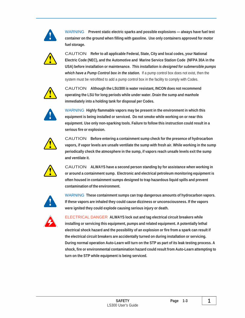
WARNING Prevent static electric sparks and possible explosions — always have fuel testcontainer on the ground when filling with gasoline. Use only containers approved for motorfuel storage.
CAUTION Refer to all applicable Federal, State, City and local codes, your NationalElectric Code (NEC), and the Automotive and Marine Service Station Code (NFPA 30A in theUSA) before installation or maintenance. This installation is designed for submersible pumpswhich have a Pump Control box in the station. If a pump control box does not exist, then thesystem must be retrofitted to add a pump control box in the facility to comply with Codes.
CAUTION Although the LSU300 is water resistant, INCON does not recommendoperating the LSU for long periods while under water. Drain the sump and manholeimmediately into a holding tank for disposal per Codes.
WARNING Highly flammable vapors may be present in the environment in which thisequipment is being installed or serviced. Do not smoke while working on or near thisequipment. Use only non-sparking tools. Failure to follow this instruction could result in aserious fire or explosion.
CAUTION Before entering a containment sump check for the presence of hydrocarbonvapors, if vapor levels are unsafe ventilate the sump with fresh air. While working in the sumpperiodically check the atmosphere in the sump, if vapors reach unsafe levels exit the sumpand ventilate it.
CAUTION ALWAYS have a second person standing by for assistance when working inor around a containment sump. Electronic and electrical petroleum monitoring equipment isoften housed in containment sumps designed to trap hazardous liquid spills and preventcontamination of the environment.
WARNING These containment sumps can trap dangerous amounts of hydrocarbon vapors.If these vapors are inhaled they could cause dizziness or unconsciousness. If the vaporswere ignited they could explode causing serious injury or death.
ELECTRICAL DANGER ALWAYS lock out and tag electrical circuit breakers whileinstalling or servicing this equipment, pumps and related equipment. A potentially lethalelectrical shock hazard and the possibility of an explosion or fire from a spark can result ifthe electrical circuit breakers are accidentally turned on during installation or servicing.During normal operation Auto-Learn will turn on the STP as part of its leak testing process. Ashock, fire or environmental contamination hazard could result from Auto-Learn attempting toturn on the STP while equipment is being serviced.

1 Page 1-4 SAFETYLS300 User’s Guide
CAUTION Petroleum is carcinogenic – use adequate protection to avoid health hazards.ALWAYS cleanup and dispose of used absorbent/rags and petroleum resistant gloves inapproved waste containers. Cleanup refuse and dispose of these immediately to avoidpersonnel injury from vapors or direct skin contact to also avoid possible fire orenvironmental safety hazards.
This leak detector is designed for use in specific applications and in compliance withindustry standards and practices. Using it in applications for which it was not designed orfailure to follow industry standards and practices may cause the product to malfunction orfail.
CAUTION DO NOT exceed the 500 feet limit (152 m), maximum distance, between theLS300 Console and the LSU300 Transducers. Lengths exceeding the 500 feet limit (152 m)could cause unreliable system operation, which may result in creation of environmentalhazards in the event that a leak is undetected.

MECHANICAL INSTALLATION Page 2-1 2LS300 User’s Guide
2 Mechanical Installation
Mechanical Installation Sequence:Follow the instructions here to mount the LS300 Auto-Learn console and to install the LSU300 LeakSensing Unit transducers, and Needle Valves at each STP containment sump (see Figure 2.2 fortypical finished installation). Be sure to ask the electrician to do any “electrical” type of work whenappropriate.
1.) Mount the LS300 Console on a vertical surface using appropriate fasteners, level, and between 2feet (0.6 m) and 6 feet (1.9 m) high for use (see Figure 2-1 and make allowances for conduit runsand fittings at the left, right and bottom sides)
The LS300 AutoLearn console must be located in a pollution degree 2 environment per IEC60664 incontries requiring CE compliance.
2.) At the electrical power panel: locked-out & Tag POWER OFF for the STP’s, Pump Controllers, andDispensers
DANGER Electronic line leak detectors start submersible pumps automatically to run leak-testsat full line pressure. Automatic pump starts occur between periods of product dispensing when thereis no product being dispensed. BEFORE performing any installation or service (such asreplacing fuel-filters) – tag and lockout all electrical power sources to the submersiblepump(s), pump controllers, and dispensers and relieve fuel-line pressure. Failure to turn offpower and relieve fuel-line pressure before work is started can result in: pressurized fuelspills (an environmental hazard associated with costly cleanups), and fire or explosion hazardthat may result in injury or death.
WARNING Avoid personnel injury or property damage: ALWAYS secure the hazardous work areafrom moving vehicles. This equipment is usually mounted underground, therefore, reduced visibilityputs service personnel working on this equipment in danger from moving vehicles entering the workarea. Use Safety Cones, Barricades, Warning Signs, and Safety Tape, and block access withBarricades / service vehicles to the work area to avoid injury or property damage.
3.) Relieve pipeline pressure to 0 psi per manufacturers recommendation and capture any product thatescapes or use absorbent rags to clean up any product spills and dispose of properly (FE PetroPumps: open Manual Pressure Relief valve / MPR valve... Red Jacket Pumps: Turn FunctionalAdjustment element to 0 psi, if no adjustment exists – remove and replace with an adjustablefunctional element)
WARNING The fuel line from the submersible pump to the dispenser, may be under pressure.Turn off all pump power and relieve pipeline pressure (reference and follow the pump manufacturer’sdirections about how to do this). If the line leak detector/plug (or any other part of the submersiblepump and fuel line) is removed without first relieving pressure, then a product leak will occur. Thiscould cause an environmental, fire, or explosion hazard, and may result in injury or death.
NOTE

2 Page 2-2 MECHANICAL INSTALLATIONLS300 User’s Guide
4.) Remove other in-line leak detection equipment before installing the LSU300 Auto-Learn LLD
5.) Apply UL Classified Gasoline/Oil resistand teflon pipe dope thread sealant to the threads of theLSU300 Transducer and use a 2-3/8 inch open-end wrench to install it in the Leak Detector Port ofthe STP housing (see Figure 2-2)
6.) Apply UL Classified Gasoline/Oil resistand teflon pipe dope thread sealant, assemble, and install thesupplied Needle Valves in the Line Pressure Test Port of the STP and close all Needle Valves (seeFigure 2-2)
7.) Install Couplings, threaded Rigid Metal Conduit (RMC), and Explosion/Weather Proof JunctionBoxes (J-Boxes) in the STP sumps (see Figure 2-2).
8.) Install threaded RMC and EYS fittings along with Transducer Cables (Belden #9365) from LS300console to the Explosion/Weather Proof J-Boxes (have the licensed electrician splice the cablestogether. If this wiring is Intrinsically Safe it MUST NOT be run with any Explosion Proof wiring orother non-Intrinsically Safe wiring!).
9.) After all LSU300 Leak Sensing Units (transducers) have been installed, check to see that all Needlevalves are closed, and that the system is ready to be pressurized to check for the absence of leaks.
10.) After the installation is checked and all personnel are clear, have the electrician turn on power at thePower Panel for the STP (Submerged Turbine Pumps and Dispensers).
11.) Turn on the STP at the dispenser (do not deliver product) and check for leaks at each Sump... ifthere are any leaks, immediately turn off power, lockout and tag at the Power Panel, use absorbentrags to clean up the product spills and dispose of properly, and repair the leak(s) and repeat step 10and step 11 until no leaks remain.
13.) Clean areas where the Danger Labels will be placed so the adhesive backing will stick to a drysurface that is clean and free of petroleum.
14.) Cleanup and dispose of installation materials, petroleum absorbent and waste material inappropriate containers.
15.) Stick the supplied Danger Labels (PN: 240-1175) to clean dry areas nearDispenser Fuel Filters, Pump Controllers, and on the Cable of theLSU300 Transducer and on the STP housing.
FIRE, EXPLOSION &ELECTRICAL SHOCK HAZARD
Electronic line leak detectorinstalled—the pump may start at any
time and pressurize the fuel lines.
• BEFORE performing anyinstallation or service — turn off/lock out electrical power sourcesto the submersible pump(s), andrelieve fuel-line pressure.
INCON PN 240-1175 Rev. D
DANGER

MECHANICAL INSTALLATION Page 2-3 2LS300 User’s Guide
TS-LS300 ConsoleDimensionsin inches and (mm) –
Enclosure Only:11.75H x 10.75L x 3.75D(298H x 273L x 95D)
With Door Closed:12H x 11L x 4D(305H x 279L x 102D)
Dual-Sized Conduit Knockouts:1/2 or 3/4 inch NPT(DN13NPT or DN20NPT)
DispenserHooks
LSU300Transducers
RS232 Comm Port
OptionalTS-TPI to
TS Console
InputPower
H
LD
Figure 2-1 LS300 Console Mounting Dimensions & Knockout Locations
11.75(298 mm)REF
HINGE SIDE ofCONSOLE DOOR 11.00 x 12.00 (280 x 305 mm)
CONSOLE DEPTH4.00 (102 MM)REF
10.75 (273 mm) REF
0.31 (8 mm)TYP.1.00
(25 mm)TYP.
13.38(340 mm)REF
0.31 (8 mm)THRU MOUNTING HOLES
TYP. FOUR PLACES
7.00 (178 mm)
12.75(324 mm)
1.50(38mm)TYP.

2 Page 2-4 MECHANICAL INSTALLATIONLS300 User’s Guide
Figure 2-2 Needle Valve Kit & LSU300 Mounting
5.13INCHES(130.18
mm)
2-3/8INCHES
(69.85 mm)ACROSS
FLATS
STPHOUSING
NORMALOPERATIONAL
VIEW
(NEEDLEVALVE KIT) @
LINE PRESSURETEST PORT
LSU300TRANSDUCER
2 INCH NPT(DN50 NPT)
NEEDLE VALVEACCESSORYKIT(UNASSEMBLED)REF: 020-10291 REQ'D ATEACHSTP HOUSING
6.25INCHES(158.75
mm)
LSU300Leak
SensingUnit
Transducer
3/4 INCHNPT
(DN20NPT)
See Figures3-2 and 3-3for Electrical installation detailsand CE approval notes

ELECTRICAL INSTALLATION & WIRING Page 3-1 3LS300 User’s Guide
3 Electrical Installation & Wiring
Electrical Installation & Wiring Sequence:
Basic Installation & Wiring
Follow the instructions here to wire the LS300 Auto-Learn console, theLSU300 Transducers from each STP containment sump, the DispenserHook Inputs, and Console Power Input. (see Figure P-1 & Figure 3-1).Ask the service tech to do “mechanical - pump/dispenser” work ifappropriate.
1.) All cables from the LSU300 transducer to the LS300 console must be installed in metal conduit incountries requiring CE compliance. Power and communication wires do not need metal conduitunless it is required by local code.
WARNING Avoid personnel injury or property damage: ALWAYS secure the hazardous work areafrom moving vehicles. This equipment is usually mounted underground, therefore, reduced visibilityputs service personnel working on this equipment in danger from moving vehicles entering the workarea. Use Safety Cones, Barricades, Warning Signs, and Safety Tape, and block access withBarricades / service vehicles to the work area to avoid injury or property damage.
2.) At the electrical power panel: locked-out & Tag POWER OFF for the STP’s, Pump Controllers, andDispensers.
ELECTRICAL DANGER Hook inputs are 120/240 Vac. Disconnect all high voltage sources beforeaccessing internal electronics
DANGER Electronic line leak detectors start submersible pumps automatically to run leak-tests atfull line pressure. Automatic pump starts occur between periods of product dispensing when there isno product being dispensed. BEFORE performing any installation or service (such as replacingfuel-filters) – tag and lock-out all electrical power sources to the submersible pump(s), pumpcontrollers, and dispensers and relieve fuel-line pressure. Failure to turn off power andrelieve fuel-line pressure before work is started can result in: pressurized fuel spills (anenvironmental hazard associated with costly cleanups), and fire or explosion hazard that mayresult in injury or death.
3.) If not done during Mechanical Installation, chapter 2, Run 3 conductor shielded cable from eachExplosion proof/Weatherproof Junction Box in the STP sump where the LSU300 Transducer isinstalled, to the LS300 console for Transducer wiring leaving about an 8 inch (203 mm) service loop(Figure 3-2 & 3-3). Label/Mark each cable jacket with the Tank # / LSU300 Transducer number.
1
TS-LS300Auto-Learn
ConsoleInputs (#1-4):
Lines (#)
Hooks (#)
PowerNOTE

3 Page 3-2 ELECTRICAL INSTALLATION & WIRINGLS300 User’s Guide
DispenserHooks
LSU300Transducers
RS232 CommPort
OptionalTS-TPI to
TSConsole
InputPower
Figure 3-1 Typical – Partial Installation & LS300 Console Conduit Designations
FE P
etro
UST
Annunciator Legend
HAZARDOUS AREA CLASS 1, DIVISION 1, GROUP C & D
NON-HAZARDOUS AREA
FE Petro Models: SCI & VFC4Turbine Pump Controllers (TPC)
MANHOLE & COVER
STP
STP Power
TS ATGConsole
Annunciator States/Conditions
Auto-Learn Line Leak DetectorTS-LS300
LS300AutoLearnConsole
H
LD
LSU300LLD
TransducerLS300Auto-Learn LLD
Console

ELECTRICAL INSTALLATION & WIRING Page 3-3 3LS300 User’s Guide
Figure 3-2 LSU300 Intrinsically Safe Wiring w/ No-Strip Wire Splice atWeatherproof Junction Box
Wire Intrinsically Safe LSU300 transducers only toTS-LS300 version consoles in conduit apart from non-intrinsically safewiring. DO NOT run intrinsically safe wiring in the same conduit with non-intrinsically safe wiring.
NOTE
Beldon #9363-22 AWG, #9364-20 AWG, #9365-18AWGor equivalent recommended. Max Cable length is 500 feet.
LS300 Auto-LearnLine Leak DetectorConsole (CU)
3 CONDUCTORCABLE 6FT (1.83 meters)Supplied
SyphonPlug
TankPlug
Follow all federal, state, and locallaws & codes governing the installation of this product & the entire system.
Maximum safe area voltage mustnot be greater than 250 Vrms.
TO SPLICE: INSERTUNSTRIPPEDWIRES & USE SLIP-JOINT PLIERS TO SEAT BLACK PIECE
BLK
SHIELD
WHT
BLK
SHIE
LD
WHT
RED
Annunciator States/Conditions
Auto-Learn Line Leak Detector
4
3
2
1
TS-LS300
TEST/
RESET
TEST
PASSED
ALARM
FAILED
Annunciator Legend
HIPUMP ON
LO
RED
ALARM
FAILED
ALARM
FAILED
ALARM
FAILED
INTELLIGENT CONTROLS
PRESSURE
PRESSURE
PRESSURE
PRESSURE
HIPUMP ON
HIPUMP ON
HIPUMP ON
TEST/
RESET
TEST/
RESET
POWER
TEST/
RESET
LO
LO
TEST
PASSED
TEST
PASSED
LO
TEST
PASSED
R
No-Strip ElectricalConnectors inside
WeatherProof J-Box
(Junction Box)5 FT (1.53 meters)MAX from LSU300
Transducer
LSU300Pressure
Transducer
STPHOUSING
Coupling
EYS (Epoxy Y Seal)Fitting TYP
3/4 inch NPT Conduitand Fittings(DN20NPT)
for I.S. Wiring Only- Typical -
For CEcompliance thecables from theconsole to theLSU300Transducer mustbe installed inmetal conduit,rigid or flexible
NOTE

3 Page 3-4 ELECTRICAL INSTALLATION & WIRINGLS300 User’s Guide
Figure 3-3 LSU300E Explosion Proof Transducer Wiring atExplosion Proof Junction Box
Wire Explosion Proof LSU300E transducers only to TS-LS300E consoles in accordance withapplicable standards. Explosion proof J-Boxes and conduit fittings must be used in thisapplication in hazardous locations. This wiring does not require separation from other non-intrinsically safe wiring.
This method can be used for retrofit installations where separate conduit is not available.
NOTE
Beldon #9363-22 AWG, #9364-20 AWG, #9365-18AWGor equivalent recommended. Max Cable length is 500 feet.
3 CONDUCTORCABLE 6FT (1.83 meters)Supplied
SyphonPlug
TankPlug
LS300E Auto-LearnLine Leak DetectorConsole (CU)
Follow all federal, state, and locallaws & codes governing the installation of this product & the entire system.
Maximum safe area voltage mustnot be greater than 250 Vrms.
TO SPLICE: INSERTUNSTRIPPEDWIRES & USE SLIP-JOINT PLIERS TO SEAT BLACK PIECE
BLK
SHIELD
WHT
BLK
SHIE
LD
WHT
RED
Annunciator States/Conditions
Auto-Learn Line Leak Detector
4
3
2
1
TS-LS300
TEST/
RESET
TEST
PASSED
ALARM
FAILED
Annunciator Legend
HIPUMP ON
LO
RED
ALARM
FAILED
ALARM
FAILED
ALARM
FAILED
INTELLIGENT CONTROLS
PRESSURE
PRESSURE
PRESSURE
PRESSURE
HIPUMP ON
HIPUMP ON
HIPUMP ON
TEST/
RESET
TEST/
RESET
POWER
TEST/
RESET
LO
LO
TEST
PASSED
TEST
PASSED
LO
TEST
PASSED
R
No-Strip ElectricalConnectors inside
Explosion ProofJ-Box
(Junction Box)5 FT (1.53 meters)
MAX from LSU300ETransducer
LSU300EPressure
Transducer
STPHOUSING
Coupling
EYS (Epoxy Y Seal)Fitting TYP
3/4 inch NPT Conduit(DN20NPT)
w/ Explosion Proof Fittings
- Typical -

ELECTRICAL INSTALLATION & WIRING Page 3-5 3LS300 User’s Guide
4.) Remove a portion of the cable jacket (service-loop) inside the J-Box, and install the no-strip electricalconnectors inside the J-Box (see Figures 3-2 & 3-3).
5.) Verify that all connections are correct and that the like colored and unstripped wires are fully insertedinto the no-splice connectors (RED to RED, WHITE to WHITE, BLACK TO BLACK, and SHIELDDRAIN to SHIELD DRAIN) and are spliced together... make sure that the black, oval-shapedcompression part is firmly seated down into the connector with slipjoint pliers (see Figures 3-2 & 3-3). Install J-Box cover after wire-splicing is completed and checked.
6.) Remove the metal Terminal Safety Guard and Wire LSU300 Transducers to the Transducer Inputchannel terminals inside the LS300 console. See Figure 3-4 for Tank, Line, and Productassociations, and TABLE 3-1 for wiring. Maintain these associations accurately when wiringTransducer and Hook Input terminals.
Channel N must operate the STPs at Tank/Line N
A.) Strip off 3/16 of a inch (5 mm) of insulation from the ends of each conductor
B.) Wire Transducers # 1 – 4 (see Figure 3-4). Make sure all wiresare fully inserted and clamped at the terminal block. Make sureno stray strands of wire are shorting to adjacent terminal blockconnections.
C.) Install the metal Terminal Safety Guard after verifying allTransducer Input Channel wiring is correct
D.) Verify that all splices in the manhole Junction Boxes areaccurate
E.) Lastly, install the Explosion proof/Weatherproof Junction BoxCovers
WARNING Never power up the LS300 console when the terminalsafety guard is removed
Basic Installation & Wiring – all Applications (Continued... )
NOTE
Photo 3-3Transducer Inputs

3 Page 3-6 ELECTRICAL INSTALLATION & WIRINGLS300 User’s Guide
Figure 3-4 Dispenser Hook and Console Interface
Photo 3-4Hook Inputs
Note, the color ofsome componentsmay be different
dependingon Supply
Manufacturer
+V = 15 VDC OUTPUTRED
RED
DispenserHook
Isolation
OUTPUT:
DISPENSER HANDLEINPUTS:
SUPPLY
RETURN
RETURNBLK
BLK
SUPPLY
RETURN
RED
BLK
SUPPLY RED
TS-LS300 Auto-Learn Console
HOOKSCh1, Ch2Ch3, Ch4
HOOK INPUT:
SubmersiblePump
Controller
TS-TPIPCB
POWERIN
TRANSDUCER'SCh1, Ch2Ch3, Ch4
OPTIONAL
BLKL1L2 (240 v) or N (120 v)
GROUNDGROUND
ElectricalPowerPanel
WHTGRNGRN
SIGNAL
IN
GROUNDGROUND
OUT
+V
BLKSHIELD
RED
RED
WHT
RETU
RN
SUPPLY
DISPENSERHANDLESWITCH
SHIELD
LSU300TRANSDUCER
LINE / TANKHOOK =
CHANNEL # N
BLK
SHIELD
BLK
REDWHT
RED
WHT
120 v 240 vBRNBLU
GRN/YELGRN/YEL
Basic Installation & Wiring (Continued... )7.) Wire Dispenser Hooks (switches) to the Hooks terminals inside the LS300 console, see Figure 3-4.
A.) Follow these associations accurately when wiring.Hook 1 must operate the STP at Tank/Line 1, Hook 2 for Tank/Line 2,Hook 3 for Tank/Line 3, Hook 4 for Tank/Line 4.
B.) Wire the Hook Inputs to the proper Channels, to Turbine Pump Controllers, and toDispenser Hook Isolators as shown in Figure 3-4.

ELECTRICAL INSTALLATION & WIRING Page 3-7 3LS300 User’s Guide
Basic Installation & Wiring (Continued... )8.) Wire Console Power to the Power Input terminals
inside the LS300 console (see Figure 3-4):
A.) Install / use a 10 ampere Circuit Breaker atthe Electrical Power Panel that isdedicated/and used only for the LS300Console(s).
ELECTRICAL DANGER Match the voltageshown on the Lower Left side label only whenselecting the console input power source,otherwise damage to the LS300 console willresult. Any equipment damage caused by usingthe incorrect input power source is not becovered under warranty.
CAUTION DO NOT use this circuit breaker for any other equipment, otherwise electrical noisemay affect the operation and reliability of the LS300 LLD system!
B.) Remove the clear plastic, Terminal Safety Guard at the console and run wire within 1/2 inchor 3/4 inch ( mm) RMC — size wire to the circuit breaker used and length of run (14 gauge isrecommended).
C.) Wire according to TABLE 3-1 for 120 v power or TABLE 3-2 for 240 v power:
TABLE 3-1 LS300 Console Input Power From/To Wire List 120Vac
TABLE 3-2 LS300 Console Input Power From/To Wire List 240Vac
SW1F1 F2
Photo 3-5Input Power

3 Page 3-8 ELECTRICAL INSTALLATION & WIRINGLS300 User’s Guide
Enclosure
Nut
Lock Washer
Earth Ground ConductorCup Washer
Stud: #8 threaded post
Figure 3-5Ground Stud
9.) Ground Stud: The installer is to connect the Earth Ground Conductor to the most convenientground terminal as long as it meets local and national codes. If the ground stud is to be usedthe installer shall follow the proper stacking configuration shown in figure 3-5. The earthground conductor must be 12 AWG or larger.

LINE CALIBRATION (LEARN MODE) Page 4-1 4LS300 User’s Guide
4 Line Calibration
NOTE ! Before Calibrating a Line:
1.) A PRECISION LINE TEST MUST BE CONDUCTED on each line before installing the LS300 Auto-Learn® LLD system for the first time, or before replacing, or before adding a new LSU300 LLDTransducer.
2.) USE A PRESSURE GAUGE TO VERIFY THAT EACH LINE IS STABLE. THE PRESSURECHANGE WITHIN THE PIPELINE AFTER 5 MINUTES OF PUMP-OFF MUST BE LESS THAN 5PSI. The LS300 Auto-Learn LLD system will not calibrate properly unless the product is stable inpipeline.
3.) A LEAK GENERATOR DEVICE/CALIBRATION KIT (SUPPLIED) MUST BE INSTALLED AT THESTP TO PERFORM CALIBRATION OR MANUAL TESTING. Follow steps 1 to 12 and see Photo 4-1for this installation.
4.) Turn on and CALIBRATE ONLY ONE CHANNEL AT A TIME! When that channel is complete, turnoff that channel and turn on the next channel to calibrate.
5.) ALWAYS PLACE THE RUN STOP (SW3) IN THE STOP POSITION, AND WAIT 10 SECONDSBEFORE MOVING ANY OTHER SWITCH.
Configuration Slide-SwitchesRUN STOP SW3 always position to STOP {down}and wait 10 seconds before moving any other slide-switch
LEARN CH-N DETECTSW4 = Channel-1 / Line #1SW5 = Channel-2 / Line #2SW6 = Channel-3 / Line #3SW7 = Channel-4 / Line #4
CHANNEL ENABLE SW2miniature slide-switches forchannels/lines # 1 to 4(ON / ENABLE = up & OFF= down)
The Run Stop and LearnDetect-switches are in theconsole at the upper-left.
Photo 4-1 Channel / Learn
ON
OFFNOTE

4 Page 4-2 LINE CALIBRATION (LEARN MODE)LS300 User’s Guide
Line Calibration Steps
Steps to Install the Leak Generator Device {Calibration Kit}The Leak Generator Device can be installed during the Mechanical Installation of the needlevalve, See chaper 2.
1.) Disconnect power, Lock out and Tag the electrical circuit breakers to the submersible pump,dispensers and related devices at the electrical supply box associated with the product line to beworked on.
ELECTRICAL DANGER ALWAYS lock out and tag electrical circuit breakerswhile installing or servicing this equipment, pumps and related equipment. Apotentially lethal electrical shock hazard and the possibility of an explosion or firefrom a spark can result if the electrical circuit breakers are accidentally turned onduring installation or servicing.
WARNING Before commencing with the installation of a leak generator device,secure the work area by using safety cones, barricades, trucks, etc.
2.) Make sure the Needle Valve is closed, turned completely clockwise, or relieve the line pressure tozero and then remove the Brass Plug (Figure 4-1).
3.) Apply UL-classified non-hardening, non-toxic pipe thread sealant to the 1/4-inch threads of the LeakGenerator Device (Figure 4-1).
4.) Install the Leak Generator Device in the place of the Brass Plug (Figure 4-1). Install a 0-60 psipressure gauge, obtained locally, into the product line (Figure 4-1).
5.) Place and secure the orifice of the Leak Generator into a suitable container, minimum 5-galloncapacity.
* The needle valve kit and the calibration kit have not been evaluated byUnderwriters Laboratories.
CAUTION Take steps to prevent foreign materials from getting into the orificeof the leak generator device. Foreign matter may block flow through the orifice andprevent proper calibration or give inaccurate results during a test. Never attempt toclean the orifice, as damage and improper calibration may result.
Do not allow the orifice to be submerged or blocked during the calibration or testingprocess.
WARNING ALWAYS secure the Leak Generator Device in the container. Whenthe submersible pump is turned on a fine stream will be sprayed out the orifice ofthe Leak Generator Device. This stream can cause the orifice to move andpossibly come out of the container. The stream can cause physical injury andenvironmental issues.
NOTE
NOTE

LINE CALIBRATION (LEARN MODE) Page 4-3 4LS300 User’s Guide
6.) If not done in chapter 3, Wire the dispenser hook signal to the proper channel associated with theproduct line being worked on (Figure 4-2).
7.) Turn power on at the load center to LS300 Auto-Learn®, pumps andrelated equipment for product with Leak Generator Device installed.Turn RUN/Stop switch to STOP. For the channel to be learned installthe Leak Generator Device in the line, if not already done, set theCHANNEL ENABLE Switch to ON, the LEARN/DETECT Switch toLEARN (See Figure 4-2) and set all other channel enable switches toOFF. Wait 10 seconds, and then set the STOP/RUN switch to RUN(See Figure 4-3). Verify the Calibration Kit is secure to a suitablecontainer and energize the submersible for this product. CheckTransducer and Leak Generator Device installation for leaks. If there
Figure 4-1 Leak Generator Device {Calibration Kit} & Pressure Gauge at STP
LEAK GENERATOR CALIBRATIONKIT AT STP(NEEDLE VALVE) ...ONLY ONE LINEIS CALIBRATED ATA TIME DURINGLS300 AUTO-LEARNMODE
LS300CALIBRATION KIT ABOUT 72 INCHES(182.88 cm) LONGREF: 020-03151 REQUIRED PER SYSTEM
PRESSUREGAUGE
Figure 4-3 Run/StopSwitch

4 Page 4-4 LINE CALIBRATION (LEARN MODE)LS300 User’s Guide
Figure 4-2 LS300 Console Circuit board Layout
Red White Black Shield
Hook In: From dispenser
Hook Out: To Pump Controller
HookTerminalBlocks
Fuse F2 (Over-current protection)
Fuse F1 (Hook Input Circuits) Input VoltageSelector
Channel Enable Switch
Learn/DetectSwitches
TransducerTerminal Blocks
InputPowerL1L2 (or N)GroundGround
Run/Stop Switch
115V 230V
Up-Enable
Down-Disable

LINE CALIBRATION (LEARN MODE) Page 4-5 4LS300 User’s Guide
are any leaks, immediately turn off the power at the load center, lock out and tag out breakers, andrepair the leaks before proceeding.
When making changes to the switch settings, LEARN/DETECT or CHANNELENABLE switches, the STOP/RUN switch must be moved to the STOP position forten seconds, after the switch changes are completed, before the changes will takeeffect and returning the console to RUN.
8.) Purge remaining air from the system as follows: Dispense enough gasoline from the dispenserfarthest from the pump to remove all the air from that line. Repeat this procedure with eachdispenser, working your way back to the pump (other methods may be used as long as the air isremoved). Also open the Needle Valve to the Calibration Kit and remove air from this area. TheLS300 Auto-Learn® will not calibrate properly if all of the air is not removed from the system. Oncecomplete, close the Needle Valve and turn off the submerged pump.
During the calibration process, no other activity should take place on this productline. Product line stability is key to proper calibration of the LS300 console.Calibrate only one channel at a time, completing the calibration process in a timelyfashion.
If the Leak Generator Device is not installed in the line to be calibrated follow steps11 to 18 of Leak Generator Device Installation Section (see Figure 4-1). LeakGenerator Device must be installed in line to perform calibration.
9.) Energize the submerged pump and pressurize this product line. With the pump OFF, a pressuregauge in the pipeline, and a minimum line pressure of 17.5 psi, ensure that the pressure change ineach pipeline is less than 5 psi within 5 minutes before beginning calibration process.
CAUTION Static line pressure must conform to Step 9 before proceeding withthe calibration process. Improper static line pressure values can prevent propercalibration, which could result in not properly detecting line leaks in this system.Repeat Step 9 until proper values are obtained or call Technical Support at (800)984-6266 for assistance.
10.) Open the Needle Valve to the Leak Generator and completely bleed the line pressure to zero psi.Allow needle valve to remain open during the calibration process, as this is necessary for propercalibration.
After opening the needle valve to the Leak Generating Device, ensure that the fuelflow through the orifice is a steady stream from pump OFF pressure to zero linepressure. If there is not a steady stream, or line pressure does not drop completelyto zero, replace the Leak Generating Device or call Technical Support at (800) 984-6266 for assistance. Never attempt to clean the orifice, as damage, or impropercalibration, may result.
NOTE
NOTE
NOTE
NOTE

4 Page 4-6 LINE CALIBRATION (LEARN MODE)LS300 User’s Guide
WARNING Prevent Static electric sparks and possible explosion by placingcontainer on ground. Always have container on the ground when filling withgasoline. Use only containers approved for motor fuel storage.
11.) Switch the STOP/RUN switch to STOP (Figure 4-3). See Figure 4-2 for switch location.
12.) Verify Mode Select Switch for this channel is in the LEARNposition (Figure 4-4).
13.) Verify the CHANNEL ENABLE Switch for this channel is inthe Enabled (ON) position (Figure 4-2).
When making changes to the switch settings,LEARN/DETECT or CHANNEL ENABLE switches,the STOP/RUN switch must be moved to theSTOP position for ten seconds, after the switchchanges are completed, before the changes willtake effect and returning the console to RUN.
14.) Wait 10 seconds, and then switch the STOP/RUN switch to RUN.
15.) Press the TEST/RESET button on console cover to enter the learn mode.
16.) The HI, LOW and TEST indicator lamps will blink, indicating the unit is ready to learn.
During the calibration process, the LS300 Auto-Learn® console learns thezero pressure point, turns ON the pump for at least 10 seconds, and learnsthe specific characteristics of a leak for the system (this may take severalminutes depending on piping system installed).
17.) Press and hold the TEST/RESET button until the LO light comes on, approximately one to twoseconds.
When the Console HI lamp starts blinking during the calibration process, the pumpwill be on.
18.) The calibration process for this channel is successfully completed when the TEST lamp stopsblinking, and the HI, LOW and TEST indicator lamps are ON steady or all OFF. SeeTroubleshooting Guide for further details on lamp indications.
The ALARM indicator lamp indicates abnormal conditions during thecalibration. Go to Learn Mode (Calibration) Troubleshooting Guide to assistin correcting conditions. When alarm condition is corrected, redo calibrationprocess from Step 9.
19.) Switch the STOP/RUN switch to STOP
20.) Set the Mode Select Switch to DETECT.
21.) Wait ten seconds, and then switch the STOP/RUN switch to RUN.
NOTE
NOTE
Figure 4-4 Learn/Detect Switch
NOTE
NOTE

LINE CALIBRATION (LEARN MODE) Page 4-7 4LS300 User’s Guide
22.) Press the TEST/RESET button to put channel into detection mode.
23.) Verify the channel learned the pipeline correcly by manually starting a Gross (3 GPH) leak test withthe Leak Generator Kit still installed and the Needle Valve still open, see Chapter 5 LS300 consoleOperation for manual start of leak tests. If the leak is not detected, repeat the Calibration process orcall Technical Support at (800) 984-6266 for assistance.
24.) Disconnect power, Lock out and Tag the electrical circuit breakers to the submersible pumpassociated with this product line.
25.) Close the needle valve, remove the Leak Generator device and replace the Brass Plug. Remove thepressure gauge from the line and replace the pipe plug, applying UL-classified non-hardening, non-toxic pipe thread sealant to the 1/4-inch threads.
26.) Energize the submersible for this product. Check Needle Valve area for leaks. If there are anyleaks, immediately turn off the power at the load center, lock out and tag out breakers, and repair theleaks
Follow the Leak Generator Device Installation and Calibration process foreach channel that is to be used. Repeat Steps 11-27 for each product line thatthe LS300 Auto-Learn® Console is to monitor.
For Normal Operation27.) After calibration and testing is complete on all Channels to monitor, verify that all active channels
have the Mode Select Switch set to the DETECT position and the CHANNEL ENABLE switch set tothe ON position. If switch changes are made, switch the STOP/RUN switch to STOP for 10seconds, and then to RUN for normal operation.
See LS300 Console Operation or Troubleshooting Guide at end of thismanual for information on verifying LS300 Auto-Learn®. Call TechnicalSupport at (800) 984-6266 for any other concerns or questions regardinginstallation or service of the LS300 Auto-Learn® system.
For installation instructions for connecting the TS-LS300 console to an Incon tankgauge, please refer to the TS-TPI Programming User’s Guide.
NOTE
NOTE

LS300 CONSOLE OPERATION Page 5-1 5LS300 User’s Guide
5 LS300 Console Operation
Line Leak Tests
For normal operation verify the following:
At the LS300 Auto-Learn® Console: For each channel in use the correspondingchannel enable switch is in the ON position. The Mode Select switch, for eachchannel in use, is set in the DETECT position. The “STOP/RUN” switch is in theRUN position.
At the STP: The needle valve is closed, the Leak Generator is removed, and thebrass plug is in place. Turn power on to the LS300 Auto-Learn®, the STP,dispensers and other equipment for the dispensing system.
To Clear Lamp Indicators and Alarms: Push the Test/Reset button on the console.When the Test/Reset button is released the lamp indicators will cycle on in thefollowing sequence: HI, LO, Test and Alarm.
Three automatic line leak tests are conducted and monitored from the LS300 Auto-Learn console.
GROSS (3.0 GPH) Leak TestThe Gross (3 GPH) leak test is initiated after each dispense cycle or after 45minutes of quiet time. The test consists of 3 consecutive tests, timed at 5-minuteintervals. If one of the three tests pass, the line is determined to have no Grossleak. If there is a failure, the test will continue until three consecutive tests fail.Three failures will cause the ALARM light to blink, the alarm HORN to sound,and the pump to shut down. If there is dispensing from the line during the testingprocess, the testing will restart as soon as dispensing is complete. Duringdispensing inactivity the Gross (3 GPH) test will repeat every 45 minutes afterpassing tests, or until there has been no dispensing (line inactive) for 3 hours.
Monthly (0.2 GPH) Leak TestWhen the line has been inactive for 3 hours, a monthly (0.2 GPH) test is initiated.This test will be performed every 5 minutes until a test has passed. If there arethree consecutive failures, with no passes, the ALARM light will flash, and theHORN will sound, indicating that there is a precision leak in the system. ThisALARM indication will not shut down the pump.
5 Page 5-2 LS300 CONSOLE OPERATIONLS300 User’s Guide
Annual (0.1 GPH) Leak TestWhen the line has been inactive for 6 hours, an annual (0.1 GPH) test is initiated.This test will be performed every 5 minutes until a test has passed. If there arethree consecutive failures, with no passes, the ALARM light will flash, and theHORN will sound, indicating that there is a precision leak in the system. ThisALARM indication will not shut down the pump.
Silence AlarmsBefore pushing the Test/reset button take note of the displayed Alarm conditon, seechapter 6 troubleshooting section. Some alarm conditions will not clear until thedetected conditon is corrected (i.e. transducer not seen).
Push the Test/Reset button on console for the Line with an active, blinking orflashing Alarm light. When the Test/Reset button is released the alarm is cleared.The audible alarm will silence and the Alarm light will stop blinking or flashing, andthe line test will continue its normal testing procedures. The Monthly (0.2 gph/0.75 Lph) tests will automatically restart after 3 hours of inactive time, and theannual (0.1 gph/0.38 Lph) test will automatically restart after 6 hours ofinactive time. DO NOT restart precision line leak tests before the 3 or 6 hourno-dispense stabilization-time has passed.
MANUAL Line Leak TestsLeak tests may be manually started at any time. The Monthly (0.2 gph) leak testrequires 3 hours of inactive time to insure a valid test. The Annual (0.1 gph) leaktests requires 6 hours of inactive time to insure a valid test. Not waiting therequired inactive time means a passed or failed test is inconclusive.
Gross (3 gph /11 Lph) test: Press and release the Test/Reset button as if clearingalarms (see above) wait for the TEST lamp to turn on then press and release theTest/Reset button again (2 Test/Reset pushbutton presses). The Pump will turn onfor 5 to 10 seconds to pressurize the line, and testing will begin. A single PASS orthree consecutive FAILURES are required to complete the Gross (3 GPH) test. Inbetween these tests, lamps will indicate whether the last test passed or failed. APASS will put Auto-Learn back into normal DETECT mode, with indicator lamps inthe OFF condition. Three consecutive FAILURES will put Auto-Learn in alarmcondition, and provide positive shut-down of the pump.
Monthly (0.2 gph/ 0.75 Lph) test: To initiate a monthly (0.2 gph) test press andrelease the Test/Reset button as if clearing alarms and wait for the TEST lamp toturn on then press and release the Test/Reset button again. Press and release theTest/Reset button a third time when the TEST lamp turns on (3 Test/Resetpushbutton presses). The Pump will turn on for 5 to 10 seconds to pressurize theline, and testing will begin. A single PASS or three consecutive FAILURES are
NOTES

LS300 CONSOLE OPERATION Page 5-3 5LS300 User’s Guide
required to complete the monthly (0.2 GPH) test. In between these tests, lamps willindicate whether the last test passed or failed. A PASS will be indicated by a singleflash on the Test indicator lamp. Three consecutive FAILURES will put Auto-Learnin alarm condition.
Annual (0.1 gph/ 0.38 lph) precision test: To initiate a manual Annual precisiontest press and release the Test/Reset button wait for the TEST lamp to turn andrepeat that sequence a total of 4 times (4 Test/Reset pushbutton presses). ThePump will turn on for 5 to 10 seconds to pressurize the line, and testing will begin.A single PASS or three consecutive FAILURES are required to complete the annual(0.1 GPH) precision test. In between these tests, lamps will indicate whether thelast test passed or failed. A PASS will be indicated by a double flash on the Testindicator lamp. Three consecutive FAILURES will put Auto-Learn in alarmcondition.
Line Leak Detection
Detected line leaks may be an actual or false line leak alarms. Treat all detectedline leak alarms as actual line leaks until verified true or false.
False line leaks can occur because of the follow reasons:product line instability (was a manual precision test started without waiting therequired 3 or 6 hour stabilization delay?), air trapped in a line or a loose fuel filter(this is likely to occur after a new installation/maintence/service ...when was the lastservice done?), thermal contractions in the line, STP/check-valve malfunction, or avapor recovery system malfunction.
DANGER A Gross (3 gph/ 11 Lph) leak is a large leak requiring immediateaction to locate and repair the source of the leak to avoid environmentalcontamination, and to avoid fire or explosion hazards. A detected GROSS leak willcause a positive pump shut-down, which will stop product dispensing.
WARNING Although monthly (0.2 gph) and annual (0.1 gph) leaks are smallerleaks, these also require action to locate and repair the leak, to avoid environmentalcontamination and to avoid fire or explosion hazards.
CAUTION DO NOT excavate / repair a fuel-line solely on the basis of asingle line leak detected alarm – confirm the presence of a leak before attempting /scheduling any repairs.

5 Page 5-4 LS300 CONSOLE OPERATIONLS300 User’s Guide
Detected Leaks
When a line leak is detected, you the owner/authorized representative must followthe steps outlined below:
1) Record (log) and identify: the type of leak test that failed (Gross test, Monthlytest, or an annual line leak test), the time it failed, the date, the product linenumber, and the product-name. Record this in a special station log at your site.
2) Inspect the piping system, dispensers, fittings, and hoses for obvious leaks.Open the dispenser enclosure and inspect the fittings and fuel filter for leaks(especially if maintenance or service was done recently).
3) Stop/ Prevent dispensing from that product line (“bag” tape a poly-bag, over theappropiate dispenser nozzels and lever). If a leak was found in Step 2 skip Steps 4& 5, and do Step # 6.
4) Reset the line at the LS300 console (initiate a manual test for the failed test) toallow a verification (re-test) for Gross, Monthly, Annual test.
5) For precision leak test failures, wait 3 hours for Monthly (0.2 gph/0.75 Lph) testfailures, or 6 hours for annual (0.1 gph/ 0.38 Lph) test failures — failed precisiontests will restart automatically when the 3 or 6 hour line-stabilization time haselapsed. The test can also be manually restart after 3 or 6 hours (reference Monthlyand Annual line leak tests in this Chapter).
6) If a leak is discovered by visual inspection, or the second (verification) lineleak test fails and detects a line leak on the same line:
a.) Immediately shut-off power to the affected pump, line, & dispenser, and callour Technical Service telephone number
b.) Take correct action in accordance with local, State, and Federal rules andregulations
c.) Contact the local inspection agency about the leak, and follow all procedures/instructions as required by law
7) A line is considered verified tight and not leaking if a second (verification)line leak test of the same or greater precision passes.
Reporting Line LeaksReporting Line LeaksReporting Line LeaksReporting Line LeaksReporting Line LeaksWhen a line leak is detected, it is the site owner’s obligation to contact the localinspection agency about line leaks, and to comply with the requirements concerningreporting and cleanup as determined by local/State/Federal Laws and Regulations.These and other regulations as required, must be followed quickly and to the letter.
WARNING Serious legal, health, and safety hazards could result from not taking the proper action within a specified time.
Where codes and regulations conflict with this manual, follow the regulations.
Compliance ReportingThe monthly or annual line leak testing requirements often vary from area to area. It is the site owner’s obligation to know the frequency of line leak testing, the compliance reporting requirements, and to comply with these requirements with appropriate documentation. Compliance is determined by local/State / Federal Laws and Regulations. Non-compliance may cause site shut-down, fines, or legal action.
The TS-TPI Turbine Pump Interface can also be wired to INCON TS-1001/TS-2001automatic tank gauges (and other future models as developed), which could provide all Tank and Line leak test Compliance Data automatically on a programmed schedule to modems/fax machines at remote sites.
NOTE: The LS300 does not have a printer. You need to interface with the TS-1001 /TS-2001 to print reports. Many localities require records showing the line tests are passing. Hand-written records of the LED status can be recorded on a monthly basis. Check with your local inspector to use this as a reporting method. See page A6 for a form that can be used for recording TS-LS300 status.
5Page 5-5LS300 CONSOLE OPERATIONLS300 User’s Guide

TROUBLESHOOTING Page 6-1 6LS300 User’s Guide
Line Pressure TransducerSignal Voltage
0 PSI 1.00 VDC5 PSI 1.20 VDC10 PSI 1.40 VDC15 PSI 1.60 VDC20 PSI 1.80 VDC25 PSI 2.00 VDC30 PSI 2.20 VDC35 PSI 2.40 VDC40 PSI 2.60 VDC45 PSI 2.80 VDC
Figure 6-1Transducer Signal Voltage
6 TS-LS300 Troubleshooting Guide
Transducer Troubleshooting
The transducer is one of the main components of the LS300 Auto-Learn system.This section is to aid in the proper troubleshooting of the transducer and its wiring.A loose or broken wire connection, or damaged insulation on a wire, can cause thetransducer to give erratic voltage readings.
Figure 6-1 shows the approximate Transducer SignalVoltage (DC) seen at the respective line pressure.
All transducers are biased slightlydifferent. Transducer VDC listings areonly approximates. Verify LinePressure by installing a pressuregauge in the line.
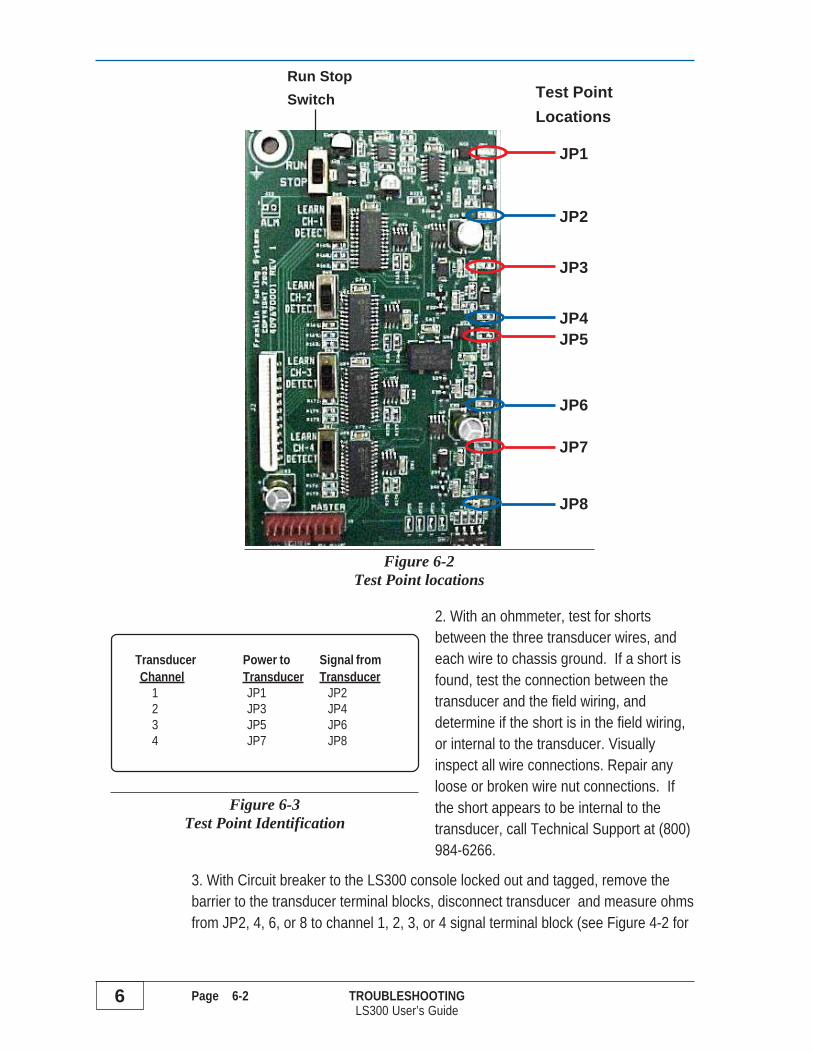
To Measure the Transducer Signal Voltage use a voltmeter and measure at the test pads on the circuit boardlabeled JP2 (channel 1), JP4 (channel 2), JP6 (channel3) or JP8 (channel 4) to Ground. Do not remove coversto the transducer terminal or the I.S. barrier. The testpads are located to the right of the Channel Learn/Detectswitches, See Figure 6-2 for test point locations.Voltages should corespond with pressures listed inFigure 6-1.
ELECTRICAL DANGER Checking Transducer Supply and Signal Voltagesis done with power applied to the LS300 Auto-Learn Console. Take care toprobe only the Transducer test points as instructed, as equipment damage orpersonal injury could result.
PROBLEM: Incorrect or erratic Transducer Signal Voltages
ELECTRICAL DANGER Before attempting the following troubleshootingmake sure power has been eliminated before removing any protectiveshields.
1. Lock out and tag Power to the LS300 Console. Verify correct wiring connectionsat transducer terminal block in the console, and the wires are properly terminatedinto the terminal block.
NOTE
6 Page 6-2 TROUBLESHOOTINGLS300 User’s Guide
2. With an ohmmeter, test for shortsbetween the three transducer wires, andeach wire to chassis ground. If a short isfound, test the connection between thetransducer and the field wiring, anddetermine if the short is in the field wiring,or internal to the transducer. Visuallyinspect all wire connections. Repair anyloose or broken wire nut connections. Ifthe short appears to be internal to thetransducer, call Technical Support at (800)984-6266.
3. With Circuit breaker to the LS300 console locked out and tagged, remove thebarrier to the transducer terminal blocks, disconnect transducer and measure ohmsfrom JP2, 4, 6, or 8 to channel 1, 2, 3, or 4 signal terminal block (see Figure 4-2 for
Transducer Power to Signal fromChannel Transducer Transducer
1 JP1 JP22 JP3 JP43 JP5 JP64 JP7 JP8
Figure 6-3Test Point Identification
JP1
JP2
JP3
JP4JP5
JP8
Figure 6-2Test Point locations
JP6
JP7
Run StopSwitch Test Point
Locations

TROUBLESHOOTING Page 6-3 6LS300 User’s Guide
Troubleshooting GuideThe LS300 Auto-Learn® LLD is equipped with indicator lamps to aid in troubleshooting and maintenance ofthe system. The 4 indicator lamps, one set for each channel, are labeled HI, LOW, TEST and ALARM.Each lamp has four possible states as follows:
• OFF (lamp is not illuminated),
• ON (lamp is illuminated steady),
• BLINK (lamp cycles equal amount of time on and off),
• FLASH (lamp cycles 4 seconds off and brief on).
The symbol NA indicates a lamp status not applicable to state, may be OFF, ON,BLINK, or FLASH).
The LS300 Auto-Learn® LLD is also equipped with an audible alarm to aid introubleshooting and maintenance of the system.
• HORN (audible alarm is sounding when this symbol is shown)
The following tables identify the different conditions of corresponding indicator lamps. The tables will listpossible causes for the conditions and proposed actions to correct the condition. Make sure to use theproper tables, either the Learn Mode section for Calibration troubleshooting or the Detect Mode section forOperation troubleshooting.
If the LS300 Auto-Learn® System does not operate correctly, or there are any questionsconcerning installation or service, call Technical Support at (800) 984-6266.
OFF
ON
B
F
NOTE
signal terminal block locations). The resistance should read about 2k ohms,if not contact Technical Support (800)-984-6266. Measure resistance frompower test points to the “+V” terminal on each channel (i.e. JP1 to channel 1“+V” terminal block). The resistance should read about 180 ohms. If it doesnot, contact Technical Support.
Hor

6 Page 6-4 TROUBLESHOOTINGLS300 User’s Guide
H
Learn Mode (Calibration) TroubleshootingHorn ON
Lamp Indicators AudibleAlarm Conditions and Possible Causes
HI LOW TEST ALARM HORN
Transducer not seenMis-wired transducer or Mis-wired Auto-Learn ® consoleTransducer failure
OFF
B
B
B
Learning Transducer Zero PSI- First step in Auto-Learn process
Learning Pump ON Pressure- Second step in Auto-Learn process
Learning Test Parameters- Last step in Auto-Learn process
Insufficient PressureConsole detected pressure less than 17.5 psi- Broken pipe or open valve- Line pressure was not bled to zero before calibration- Power to STP is OFF- STP is not operating
No Pressure Loss DetectedPressure decay was not detected- Leak generator was not installed- Needle valve on leak generator closed- Leak generator clogged
NA NA NA Memory Error- Memory failed to write
ON
B
B
B
B
B
B
B
OFF OFF
OFF OFF
OFF OFF
OFF OFF
OFF OFF
OFF
OFF
OFF
Auto-Learn Complete- Piping Modulus in range (will perform Gross, monthlyand annual tests)
Auto-Learn Complete- Piping Modulus is out of range for annual (0.1 gph)test
NA Auto-Learn Complete- Insufficient pressure for annual (0.1 gph) test
Auto-Learn Complete- Piping Modulus is out of range for the monthly (0.2gph) and annual (0.1 gph) tests
ON
ON
ON
ON
ON
ON
ON OFF
OFF
OFF OFF
OFF B B
B
T A
Horn OFF -- Learning Process
Horn OFF -- Learning Results
Hor
or

TROUBLESHOOTING Page 6-5 6LS300 User’s Guide
Detect Mode (Operation) Troubleshooting
Lamp Indicators AudibleAlarm Conditions and Possible Causes
HI LOW TEST ALARM HORN
Gross (3 gph) Leak Alarm- Leak in the system- Leak in the check valve- Leak in the manual pressure relief
NA NA NAMonthy or Annual Precision Test Failed- Monthly (0.2 gph) test failed - one flash- Annual (0.1 gph) test failed - two flashes
Transducer is not seen- Mis-wired transducer or Mis-wired Auto-Learn console- Transducer failure
Pipeline failed to hold pressure- Leak in the system- Manual Pressure Relief open- Check valve removed or stuck open
Insufficient pressure to conduct test- Leak in the system- Power to the submersible is OFF
OFF
B
Gross (3 gph) test in progress- Pressure is within limits
NA NA Waiting to retest- Last test passed
NA NA Waiting to retest- Last test failed
Monthly or Annual Precision test inprogress- Pressure is within limits
NA NA NAMonthly or Annual Precision test passed- Monthly (0.2 gph) test passed - one flash- Annual (0.1 gph) test passed - two flashes
NA NA NA Pump is ON
NA NA NA Pipeline pressure is below 7.5 psi
Calibration is incomplete- Unit will not detect leaks
ON
B
B
B
B
B
B
B
OFF OFF
OFF
OFF
OFF
OFF
OFF
OFF OFF
OFF
OFF
OFF
F
F
F
F
B
B
B
B
B
ON
ON
ON
OFF OFF
T A H
Horn ON
Horn OFF
H
H
H
H
H
or
or
or
or
or
or
6 Page 6-6 TROUBLESHOOTINGLS300 User’s Guide
Factory Support
Need Help ?Call INCON Technical Service for help with leak alarms, or with diagnostic codes.Please call if alarms occur frequently or repeatedly.
Before calling INCON:Have the LS300 console / LSU300 Serial Numbers on hand for units you’re havingtrouble with (see Warranty Registration form).
Accurately fill-in the Warranty Registration Form, on the facing page, photocopyand FAX it to INCON after the system is installed and lines are calibrated and areoperational.
Installer/Service Provider: Keep the photocopy for your records for future reference,and leave the original filled-in Warranty Registration Form in the manual for futureservice reference or use during future installations.
This Manual Must be left at the Site for future reference by the Customer and forreference by future service and technical personnel .
Return ShipmentsIf all or portion(s) the Auto-Learn system (LSU300 or LS300 CU console) must bereturned to INCON, please use the original shipping container and materials ifpossible.
Obtain a Return Material Authorization (RMA) number before returning anything toINCON. Shipments of returned equipment, which have not been authorized, will bereturned freight-collect.
Call INCON Technical Service Department from the site for RMA numbers. Ourpersonnel will give you the correct shipping address, and provide other details andinstructions that you will need when you call for the RMA number.
Return shipping damage due to inadequate or inappropriate packaging is yourresponsibility. Make sure that any return-goods shipment is insured.

TROUBLESHOOTING Page 6-7 6LS300 User’s Guide
LS300 System: Warranty Registration Form
Use a medium-point, black ink pen and fill-in the blank data below, photocopy theform, and FAX it to INCON Technical Service: FAX # 1-207-282-9002(Telephone # 1-800-984-6266).
LS300 Warranty Registration FormConsole (CU) Model No. LS300 LS300E (Expl.Proof) Check Correct One
Install Date: Serial No. (LL Console Label)
Transducer (LSU) Model No. LSU300 LSU300E (Expl.Proof) Check Correct One
(Label at LSU300 STP housing) Circle Correct Line # below
Install Date: Serial No. Line 1 / 5 (at STP)
Install Date: Serial No. Line 2 / 6 (at STP)
Install Date: Serial No. Line 3 / 7 (at STP)
Install Date: Serial No. Line 4 / 8 (at STP)
Purchased From (Rep. Name):
Installers Name & Certificate Number:
Site Information: Company Name: Telephone No.
Manager/Contact Name: Hours of Operation
Street, City, Zip, & Country:
Dispenser Mfg. Type: Are blenders used ? Yes No Check
FE IST pumps? Yes No Check RJ Big Flo® pumps? Yes No Check
Est. Functional Element Age(s)
Flex/Rigid Size Pipe Product Pump Model# STP Turbine Pump Line
Pipe I.D. Length Name FE / RJ: HP Ctrl. Model No. No.
1
2
3
4
APPENDIX A Page A-1 ALS300 User’s Guide
A Appendix A LS300 Auto-Learn® Line Leak DetectorTechnical Specifications
Auto-Learn® ConsoleSpecifications
Models: LS300 (I.S.) & LS300E (ExP)
Approvals:
Electrical Specifications
Input Power:L1 = 115 VAC +15%, –10% or
230 VAC +15%, –10% {@ SW1}= 0 VAC {N = Neutral}
Ground (2) = 0 VAC (1 Terminal = Safety Gnd)Frequency = 50 / 60 Hz (either)
Current = 1 A {115 VA} Maximum
WARNING Match the line voltagepower ratings printed on the Serial Numberlabel when wiring to the console inputpower terminals. Avoid voiding thewarranty & equipment damage – DONOT use an incorrect voltage source!
Electrical InterfaceRS232 Communication Port:
Bidirectional communications through 9-pin maleconnector at bottom of console {baud rate = 4800,format 8N1 (8 data bits, no parity, 1 stop bit)}
Optional RS485 Turbine PumpInterface (TPI):• TS-TPI 3-wire input/output from to
FE Petro pump controllers• TS-TPI 3-wire input/output to Tank
Sentinel TS-LLD terminals
Dispenser Hook Interface:1 to 4 channels, 2 wire, 115/230 VAC
Line Leak Test types:Gross 3 gph (11 lph) Manual & Auto
{after every dispense or every 45 min’s}Monthly 0.2 gph (0.8 lph) Manual & Auto
{3 hours after Gross test completes}Annual 0.1 gph (0.4 lph) Manual & Auto
{3 hours after Monthly test completes ...6 hours total}
Number of Lines Monitored:1 to 4 LSU300 Pressure Transducers
Alarm Annunciation:Piezoelectric 90 Db audio output at 10 cm andactivates under the following alarm conditions:• after a Gross Leak Test fails (3 gph/11 lph),• after a Monthly Leak Test fails(0.2 gph/0.8 lph),• after Annual Leak Test fails (0.1 gph/0.4 lph)• when a Pressure Transducer is not sensed• when a Line fails to hold pressure• insufficient line pressure to conduct test
1 to 4 Channel Test/Reset push-buttons silence alarms
Environmental SpecificationsStorage Temperature:
-4° to 140° F (-20° to 60° C)
Operating Temperature:32° to 122° F (0° to 50° C)
Operating Humidity:0 to 95 %, non-condensing
Pollution Degree:Category 2 per IEC 60664
Console Cleaning:Cloth dampened slightly in mild detergent
Splash Resistance:Not to be exposed to direct spray, splash, or drips
Console Location:Indoors: office, or nonhazardous industrialenvironment (or outdoors within a Nema 4xenclosure) no further than 500 feet (152.4 m) fromany STP housing/LSU300 transducer
WARNING The console must bemounted in a location where explosive, orflammable vapors are not presentotherwise, an explosion hazard will becreated which could result in propertydamage, injury, and death.
SafetyCircuits Intrinsically Safe for LSU300 Transducersinstalled in: Class I, Division 1, Group D (EUGroup IIA) hazardous locations,LS300E for Explosion Proof Transducers
L2 or N
NOTE

A Page A-2 APPENDIX ALS300 User’s Guide
Pressure TransducerSpecifications
Model LSU300 Transducer
Approvals:
Electrical SpecificationsInput Power = 10 to 32 VDCOutput Signal = 1 to 5 VDCSignal Ground = GroundOutput Load = 10K ohm output loadOutput Noise = < 2 mVCurrent = < 10ma
Insulation color:Red = Input Power = V+
White = Output Signal = SignalBlack = Signal Ground = Ground
Bare Wire = Shield Drain = GroundUnit is Reverse-Polarity protected
Applicable Liquid Products:Petroleum (Gasoline, Diesel Fuel, Kerosene, FuelOil, #2 Fuel Oil)
Accuracy:0.5% FS (FS=Combined Linearity, Hysteresesand Repeatability)
Auto-Learn® ConsoleSpecifications
Mechanical SpecificationsInches & ( mm):
Enclosure 11.75H x 10.75L x 3.75D(298H x 273L x 95D)
Encl. w/ Door 12H x 11L x 4D(305H x 279L x 102D)
Pressure TransducerSpecifications
Stability:0.25% FS over full operating temperature
Materials Used:Housing = Anodized AluminumPressure Transducer (wetted portions) = 17-4PH or 316 Stainless Steel
Environmental Specifications
Storage Temperature:-67° to 185° F (-55° to 85° C)
Operating Temperature:-40° to 149° F (-40° to 65° C)
Operating Pressure:Normal 25 to 29 psi (1.7 to 2.0 Bar)Transducer burst 500 psi (34.5 Bar)
Vibration:10 G peak, 20 to 2000 Hz
SafetyLSU300 transducers are Intrinsically Safe forinstallation in: Class I, Division 1, Group D (EUGroup IIA) hazardous locations, andLSU300E transducers are Explosion Proof
Mechanical Specifications
inches: (mm):6.25H x 2NPT (159H x DN50NPT)
H
LD
DispenserHooks
LSU300transducers
RS232Comm Port
OptionalTS-TPI
toTS
ConsoleInput Power
2 INCH NPT(DN50 NPT)
6.25INCHES
(159 mm)
3/4 INCHNPT
(DN20NPT)
5.13INCHES
(130 mm)
2-3/8INCHES(70 mm)ACROSSFLATS

APPENDIX A Page A-3 ALS300 User’s Guide
System Specifications
Third Party Approved Maximum Pipe LengthRIGID Pipe: 163 Gallon (617 L) & FLEXIBLE Pipe 39.5 Gallon (149.5 L)
System Approvals
Third-Party Tested & Approved using:LS300-120 Plus, A/L Algorithm (Patent Pending)
WARNING This leak detector is designed for motor fuels for blend concentrations of:· 0%-100% ethanol or methanol and gasoline 20% ETBE with 80% gasoline· 20% MTBE with 80% gasoline 17% TAME with 83% gasolineOther motor fuels that may be used with this product are Diesel, Avgas, Jet Fuel, or Kerosene. The maximumliquid viscosity for a product is 70 S.S.U. at 60° F.
CAUTION This leak detector is designed for use in specific applications and in compliance with industrystandards and practices. Using it in applications for which it was not designed, or failure to follow industrystandards and practices, may cause the product to malfunction or fail.
CAUTION The LS300 Auto-Learn® LLD can detect a leak from the STP check valve to the solenoid valveat the dispenser, assuming no other Normally Closed valve is in the pipeline system. The LS300 Auto-Learn® LLD does not detect leaks in the storage tank or the submersible pump before the check valve.
Console Replacement Parts
(1) 1/2 amp. slo-blow 5x20 250V fuse F2 for Console Overcurrent protection(1) 1 amp. 5x20 250V fuse F1 for Hook Inputs CircuitsDisplay (front panel) assembly – 4 ChannelDisplay (front panel) assembly – 2 ChannelRibbon Cable – Display to Main PC BoardMain PC Board (I.S. version)Main PC Board (Explosion Proof version) for LS300E consoles &LSU300E Explosion Proof Transducers onlyTPI PC BoardContact INCON for Order Numbers for the Replacement Parts
Spare LS300 System Parts
Spare I.S. Transducer – TS-LSU300Spare Explosion Proof Transducer – TS-LSU300E for TS-LS300E Exp.Proof consoles onlySpare Leak Generating Device/Calibration Kit – TS-ALCALSpare Accessory Kit (nipple & needle valve) – TS-ALNIP
SW1
Pipe Diameter I.D.1"
(25 mm)1 1/2"
(38 mm)1 3/4"
(44 mm)2"
(51 mm)2 1/2"
(64 mm)3"
(76 mm)4"
(101 mm)5"
(127 mm)
Max. R igid Pipe Length
3995'(1217 m )
1775'(541 m )
1304'(397 m )
998'(304 m )
639'(195 m )
443'(107 m )
249'(76 m )
159'(48 m )
Max. Flexible Pipe Length
968'(295)
430'(131 m )
316'(96 m )
242'(74 m )
154' (46 m )
107'(33 m )
60'(18 m )
38'(12 m )

A Page A-4 APPENDIX ALS300 User’s Guide
AUTO-LEARN CONTROL DRAWINGINCON PN: 000-1716 Rev. H

APPENDIX A Page A-5 ALS300 User’s Guide
AUTO-LEARN CONTROL DRAWINGINCON PN: 000-1717 Rev. D

Date Time of Day
Line # Precision test Passed?* Y or N
Alarm Indications**
Push Test / Reset***
Monthly Annual
Form to record monthly LS300 statusIf the LS300 is not connected to a printer through a TS-1001 / TS-2001
Page A6 Copy this page as neededA APPENDIX ALS300 User’s Guide
* Monthly (.2 GPH) test passed indicated by single TEST lamp FLASH. Annual (.1 GPH) test passed indicated by double TEST lamp FLASH.
** Flashing ALARM lamp may be indication of system problem. Note lamp indicators and refer to page 6-5 for more information*** After test results are recorded, press TEST/RESET button. Past test passed lamp indications will be cleared. Record results every two weeks.NOTES:
Test result recording should not take place during a line leak test. See page 6-5 for lamp indications signaling a Gross, •Monthly or Annual test
Test lamp will BLINK if doing a precision test ▫Test lamp will REMAIN SOLID if doing a 3 GPH test ▫
BLINK-lamp cycles equal time on and off•FLASH-lamp cycles 4 seconds off and brief on•
Refer to page 6-5 for complete lamp indicator information ▫A steady HI lamp indication signals that dispensing is occurring. Do not record line test results while dispensing.•

PO BOX 638 SACO ME 04072
TS-LS300 Auto-Learn® Line Leak Detector User’s Guide