pressure sensors for high temperature “sil2” version
TRANSCRIPT

180599 MAN_MELT_SIL2_04-2020_ENG
PRESSURE SENSORS FOR HIGHTEMPERATURE “SIL2” VERSION
code 80599 Edit. 09/2019 - ENG
2 80599 MAN_MELT_SIL2_04-2020_ENG
INDEX1. GENERAL INFORMATION ....................................................................................................................................................3
1.1. General information ......................................................................................................................................................31.2. Copyright .......................................................................................................................................................................31.3. Correct use ...................................................................................................................................................................3
2. MELT SENSOR AND THE MODELS .....................................................................................................................................32.1. Melt Sensor ...................................................................................................................................................................32.2. Models ..........................................................................................................................................................................4
3. TECHNICAL DATA ................................................................................................................................................................54. WEIGHT AND MECHANICAL DIMENSIONS ......................................................................................................................16
4.1. Weight .........................................................................................................................................................................164.2. Specific filling liquid .....................................................................................................................................................164.3. Mechanical dimensions ...............................................................................................................................................16
5. INSTALLATION, MOUNTING AND MAINTENANCE ..........................................................................................................175.1. Instruction and maintenance (Installation hole) ..........................................................................................................175.2. Instruction and maintenance (Sensor installation procedure) .....................................................................................195.3. Instruction and maintenance (Mechanical dimensions of transducer / drilling)...........................................................21
6. INSTALLATION AND ELECTRICAL CONNECTIONS ........................................................................................................226.1. General precautions ....................................................................................................................................................226.2. Electrical installation ...................................................................................................................................................226.3. Protection for outdoor installations of analog sensors ................................................................................................246.4. Standard reference .....................................................................................................................................................256.5. EMC and RoHS Requisites .........................................................................................................................................25
7. ON-BOARD FUNCTION ......................................................................................................................................................267.1. Autozero function ........................................................................................................................................................267.2. Fine-Autozero function ................................................................................................................................................277.3. Calibration function .....................................................................................................................................................277.4. Autospan .....................................................................................................................................................................287.5. Partial reset of the calibration values ..........................................................................................................................287.6. Total reset of the calibration values .............................................................................................................................28
8. AUTOCOMPENSATION FUNCTION ...................................................................................................................................298.1. Output signal trend as a function of temperature effect ..............................................................................................29
9. MAINTENANCE ...................................................................................................................................................................309.1. Maintenance ...............................................................................................................................................................309.2. Transport, storage and disposal ..................................................................................................................................30
10. SAFETY .............................................................................................................................................................................3111. Safety Notes ......................................................................................................................................................................35
11.1. Application .................................................................................................................................................................3511.2. Restrictions of use .....................................................................................................................................................3611.3. Maintenance and periodic checks .............................................................................................................................3611.4. Mean Time to Restoration ........................................................................................................................................3711.5. Indication on response times ...................................................................................................................................3711.6. Effects on the safety function of deviations in performance ......................................................................................3711.7. Inhibition and suspension of the safety function .......................................................................................................3711.8. Indications and alarms ..............................................................................................................................................37
12. RESOLUTION PROBLEMS ...............................................................................................................................................3813. APPENDIX A: OPERATING PRINCIPLE ..........................................................................................................................40
13.1. Mechanical construction and operation ....................................................................................................................4013.2. Strain gauge ..............................................................................................................................................................40
14. APPENDIX B: IP PROTECTION........................................................................................................................................4215. APPENDIX C: GUIDE TO SELECTION OF THE DIAPHRAGM IN CONTACT WITH EXTRUDED POLYMER ...............4316. APPENDIX D: ACCURACY CLASS ..................................................................................................................................44
16.1. Calibration curve .......................................................................................................................................................4416.2. Repeatability .............................................................................................................................................................4416.3. Hysteresis .................................................................................................................................................................4516.4. Linearity ....................................................................................................................................................................45
17. APPENDIX E: REGISTRATION MAINTENANCE .............................................................................................................47

380599 MAN_MELT_SIL2_04-2020_ENG
1. GENERAL INFORMATION
1.1. General information This manual refers to the following products: M, W, K SIL2, in compliance with the requirements of IEC/EN62061 and IEC/EN 61508 standards and must be kept near the equipment for easy reading and consultation. It must be read, understood, and strictly follow in order to avoid and prevent accidents and/or malfunctions. Gefran will not be liable for any injury to people and/or damage to property deriving from disregard of this manual.
1.2. Copyright Anyreproductionofthisdocument,evenpartialorforinternaluse,requiresGefran’sapproval.
1.3. Correct use Gefran Melt pressure sensors are designed and built to measure the pressure and temperature variable of melted plastic at different temperatures according to the filling fluid used. The correct temperature range is: • Up to 315°C, for W sensors series • Up to 400°C, for M sensors series • Up to 538°C, for K sensors series
If the sensors are used as a safety component in accordante with the Machinery Directive, the equipment builder must take all necessary precautions to ensure that any malfunctions of the Melt pressure sensor do not injury to people and/or damage to property. Installation and maintenance must only be carried out by suitably skilled and qualified personnel.
2. MELT SENSOR AND THE MODELS
2.1. Melt Sensor Gefran Melt sensors are pressure/temperature transducers and transmitters designed for use in high-temperature environments. They read media pressure up to a temperature of 538°C, and resist such high temperatures thanks to the ir special mechanical construction, in which the measurement element is isolated from the Melt. The constructive principle is based on hydraulic transmission of pressure; mechanical strain is transferred by means of a non-compressible transmission liquid. The liquid used in these sensors may be mercury (series M), FDA-approved oil (series W) or NaK (series K). Strain gauge technology translates the physical quantity (pressure) into an electrical signal. Four different designs are available: rigid rod, flexible sheathing, flexible plus thermocouple, and exposed tip. Gefran Melt sensors satisfy all installation and field requirements. The sensors can read an extremely wide range of pressures: from a version with minimum range of 0-17 bar up to a version with a scale of 0-2000 bar. All models in the catalog can be supplied in two different classes of accuracy: class M, with accuracy of 0.5% FS, and class H, with accuracy of 0.25% FS. Current and voltage output signals (different outputs available, see datasheet) allow the connection of all architectures now utilized for plastics processing machines.

4 80599 MAN_MELT_SIL2_04-2020_ENG
2.2. Models
4-20mA CURRENT OUTPUT Rigid stemME0 (Mercury)WE0 (Oil)KE0 (NaK)
Flexible stemME1 (Mercury)WE1 (Oil)KE1 (NaK)
Flexible stem+ThermocoupleME2 (Mercury)WE2 (Oil)KE2 (NaK)
Exposed tipME3 (Mercury)WE3 (Oil)KE3 (NaK)
0.5-10.5V/0.1-10.1V/0.1-5.1V VOLTAGE OUTPUT Rigid stemMN0 (Mercury)WN0 (Oil)KN0 (NaK)
Flexible stemMN1 (Mercury)WN1 (Oil)KN1 (NaK)
Flexible stem+ThermocoupleMN2 (Mercury)WN2 (Oil)KN2 (NaK)
Exposed tipMN3 (Mercury)WN3 (Oil)KN3 (NaK)
580599 MAN_MELT_SIL2_04-2020_ENG
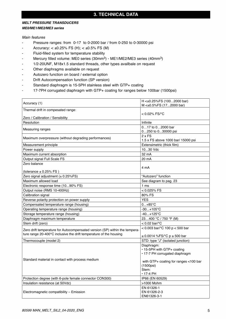
3. TECHNICAL DATAMELT PRESSURE TRANSDUCERSME0/ME1/ME2/ME3 series
Main features- Pressure ranges: from 0-17 to 0-2000 bar / from 0-250 to 0-30000 psi- Accuracy: < ±0.25% FS (H); < ±0.5% FS (M)- Fluid-filled system for temperature stability- Mercury filled volume: ME0 series (30mm3) - ME1/ME2/ME3 series (40mm3)- 1/2-20UNF, M18x1.5 standard threads, other types availbale on request- Other diaphragms available on request- Autozero function on board / external option- Drift Autocompensation function (SP version)- Standard diaphragm is 15-5PH stainless steel with GTP+ coating- 17-7PH corrugated diaphragm with GTP+ coating for ranges below 100bar (1500psi)
Accuracy (1) H <±0.25%FS (100...2000 bar) M <±0.5%FS (17...2000 bar)
Thermal drift in compesated range:
Zero / Calibration / Sensibility< 0.02% FS/°C
Resolution Infinite
Measuring ranges 0…17 to 0…2000 bar 0…250 to 0...30000 psi
Maximum overpressure (without degrading performances) 2 x FS 1.5 x FS above 1000 bar/ 15000 psi
Measurement principle Extensimetric(thickfilm)Power supply 10...30 VdcMaximum current absorption 32 mAOutput signal Full Scale FS 20 mAZero balance
(tolerance ± 0.25% FS )4 mA
Zero signal adjustment (± 0.25%FS) “Autozero” functionMaximum allowed load See diagram to pag. 23Electronic response time (10...90% FS) 1 msOutput noise (RMS 10-400Hz) < 0.025% FSCalibration signal 80% FSReverse polarity protection on power supply YESCompensated temperature range (housing) 0...+85°COperating temperature range (housing) -30...+105°CStorage temperature range (housing) -40...+125°CDiaphragm maximum temperature 23…400 °C / 750 °F (M)Stem drift (zero) < 0.02 bar/°C
Zero drift temperature for Autocompensated version (SP) within the tempera-ture range 20-400°C inclusive the drift temperature of the housing
< 0.003 bar/°C 100 p < 500 bar
≤0.0014%FS/°Cp≥500barThermocouple (model 2) STD: type “J” (isolated junction)
Standard material in contact with process medium
Diaphragm: • 15-5PH with GTP+ coating • 17-7 PH corrugated diaphragm
with GTP+ coating for ranges <100 bar (1500psi) Stem: • 17-4 PH
Protection degree (with 6-pole female connector CON300) IP66 (EN 60529)Insulation resistance (at 50Vdc) >1000 Mohm
Electromagnetic compatibility – EmissionEN 61326-1 EN 61326-2-3 EN61326-3-1
6 80599 MAN_MELT_SIL2_04-2020_ENG
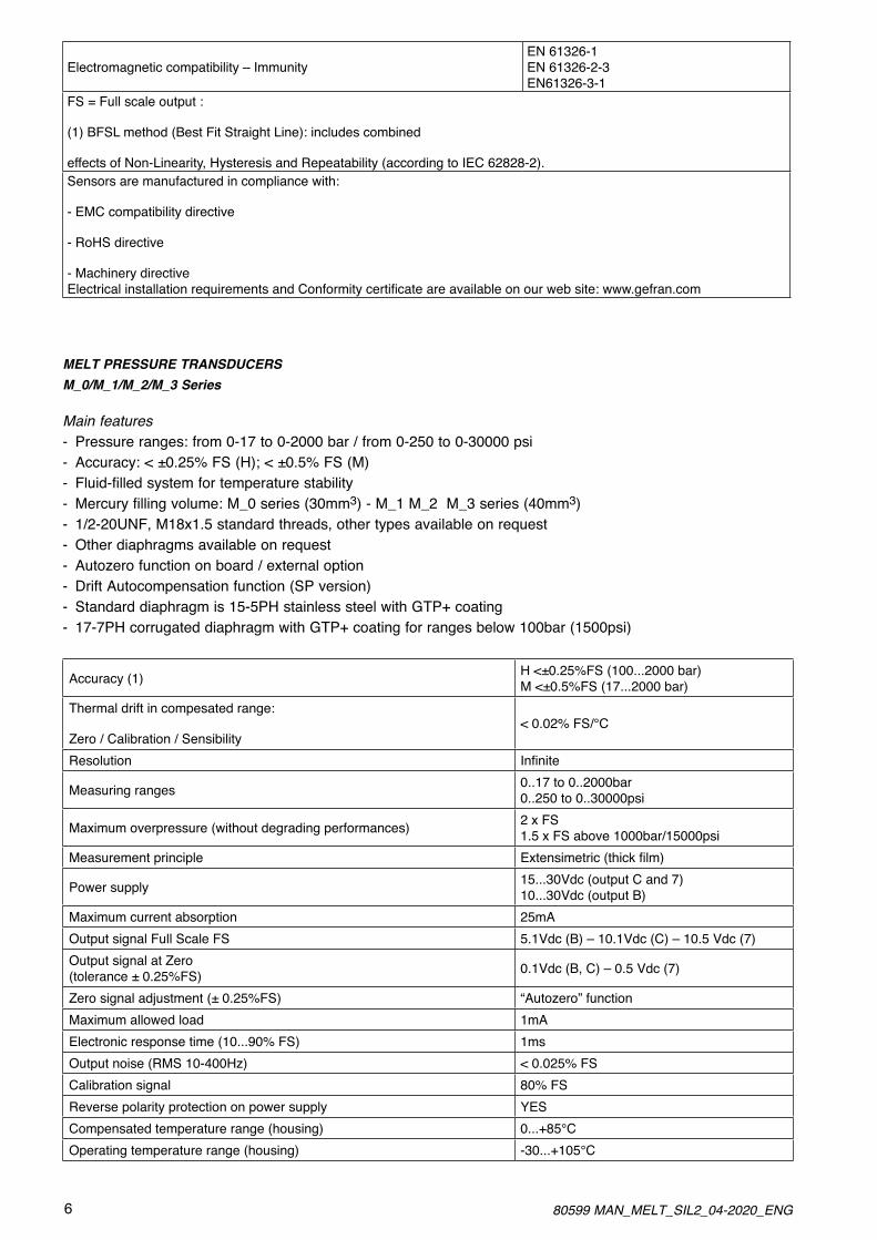
Electromagnetic compatibility – ImmunityEN 61326-1 EN 61326-2-3 EN61326-3-1
FS = Full scale output :
(1) BFSL method (Best Fit Straight Line): includes combined
effects of Non-Linearity, Hysteresis and Repeatability (according to IEC 62828-2).Sensors are manufactured in compliance with:
- EMC compatibility directive
- RoHS directive
- Machinery directive ElectricalinstallationrequirementsandConformitycertificateareavailableonourwebsite:www.gefran.com
MELT PRESSURE TRANSDUCERSM_0/M_1/M_2/M_3 Series
Main features - Pressure ranges: from 0-17 to 0-2000 bar / from 0-250 to 0-30000 psi- Accuracy: < ±0.25% FS (H); < ±0.5% FS (M)- Fluid-filled system for temperature stability- Mercury filling volume: M_0 series (30mm3) - M_1 M_2 M_3 series (40mm3)- 1/2-20UNF, M18x1.5 standard threads, other types available on request- Other diaphragms available on request- Autozero function on board / external option- Drift Autocompensation function (SP version)- Standard diaphragm is 15-5PH stainless steel with GTP+ coating- 17-7PH corrugated diaphragm with GTP+ coating for ranges below 100bar (1500psi)
Accuracy (1) H <±0.25%FS (100...2000 bar) M <±0.5%FS (17...2000 bar)
Thermal drift in compesated range:
Zero / Calibration / Sensibility< 0.02% FS/°C
Resolution Infinite
Measuring ranges 0..17 to 0..2000bar 0..250 to 0..30000psi
Maximum overpressure (without degrading performances) 2 x FS 1.5 x FS above 1000bar/15000psi
Measurement principle Extensimetric(thickfilm)
Power supply 15...30Vdc (output C and 7) 10...30Vdc (output B)
Maximum current absorption 25mAOutput signal Full Scale FS 5.1Vdc (B) – 10.1Vdc (C) – 10.5 Vdc (7)Output signal at Zero (tolerance ± 0.25%FS) 0.1Vdc (B, C) – 0.5 Vdc (7)
Zero signal adjustment (± 0.25%FS) “Autozero” functionMaximum allowed load 1mAElectronic response time (10...90% FS) 1msOutput noise (RMS 10-400Hz) < 0.025% FSCalibration signal 80% FSReverse polarity protection on power supply YESCompensated temperature range (housing) 0...+85°COperating temperature range (housing) -30...+105°C
780599 MAN_MELT_SIL2_04-2020_ENG
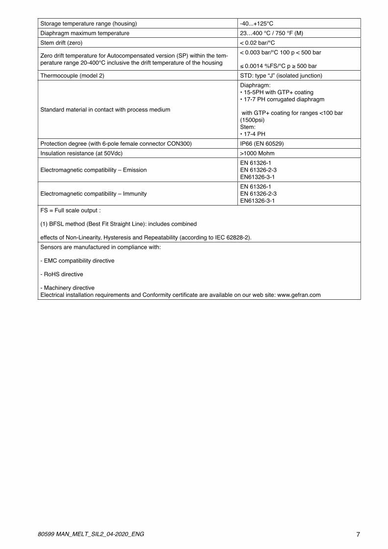
Storage temperature range (housing) -40...+125°CDiaphragm maximum temperature 23…400 °C / 750 °F (M)Stem drift (zero) < 0.02 bar/°C
Zero drift temperature for Autocompensated version (SP) within the tem-perature range 20-400°C inclusive the drift temperature of the housing
< 0.003 bar/°C 100 p < 500 bar
≤0.0014%FS/°Cp≥500barThermocouple (model 2) STD: type “J” (isolated junction)
Standard material in contact with process medium
Diaphragm: • 15-5PH with GTP+ coating • 17-7 PH corrugated diaphragm
with GTP+ coating for ranges <100 bar (1500psi) Stem: • 17-4 PH
Protection degree (with 6-pole female connector CON300) IP66 (EN 60529)Insulation resistance (at 50Vdc) >1000 Mohm
Electromagnetic compatibility – EmissionEN 61326-1 EN 61326-2-3 EN61326-3-1
Electromagnetic compatibility – ImmunityEN 61326-1 EN 61326-2-3 EN61326-3-1
FS = Full scale output :
(1) BFSL method (Best Fit Straight Line): includes combined
effects of Non-Linearity, Hysteresis and Repeatability (according to IEC 62828-2).Sensors are manufactured in compliance with:
- EMC compatibility directive
- RoHS directive
- Machinery directive ElectricalinstallationrequirementsandConformitycertificateareavailableonourwebsite:www.gefran.com
8 80599 MAN_MELT_SIL2_04-2020_ENG
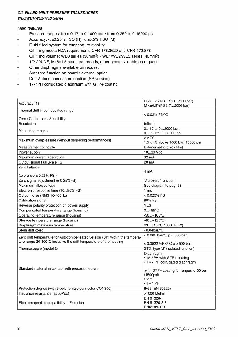
OIL-FILLED MELT PRESSURE TRANSDUCERSWE0/WE1/WE2/WE3 Series
Main features- Pressure ranges: from 0-17 to 0-1000 bar / from 0-250 to 0-15000 psi- Accuracy: < ±0.25% FSO (H); < ±0.5% FSO (M)- Fluid-filled system for temperature stability- Oil filling meets FDA requirements CFR 178.3620 and CFR 172.878- Oil filling volume: WE0 series (30mm3) - WE1/WE2/WE3 series (40mm3)- 1/2-20UNF, M18x1.5 standard threads, other types available on request- Other diaphragms available on request- Autozero function on board / external option- Drift Autocompensation function (SP version)- 17-7PH corrugated diaphragm with GTP+ coating
Accuracy (1) H <±0.25%FS (100...2000 bar) M <±0.5%FS (17...2000 bar)
Thermal drift in compesated range:
Zero / Calibration / Sensibility< 0.02% FS/°C
Resolution Infinite
Measuring ranges 0…17 to 0…2000 bar 0…250 to 0...30000 psi
Maximum overpressure (without degrading performances) 2 x FS 1.5 x FS above 1000 bar/ 15000 psi
Measurement principle Extensimetric(thickfilm)Power supply 10...30 VdcMaximum current absorption 32 mAOutput signal Full Scale FS 20 mAZero balance
(tolerance ± 0.25% FS )4 mA
Zero signal adjustment (± 0.25%FS) “Autozero” functionMaximum allowed load See diagram to pag. 23Electronic response time (10...90% FS) 1 msOutput noise (RMS 10-400Hz) < 0.025% FSCalibration signal 80% FSReverse polarity protection on power supply YESCompensated temperature range (housing) 0...+85°COperating temperature range (housing) -30...+105°CStorage temperature range (housing) -40...+125°CDiaphragm maximum temperature 23…315 °C / 600 °F (W)Stem drift (zero) <0.04bar/°C
Zero drift temperature for Autocompensated version (SP) within the tempera-ture range 20-400°C inclusive the drift temperature of the housing
< 0.005 bar/°C p < 500 bar
≤0.0022%FS/°Cp≥500barThermocouple (model 2) STD: type “J” (isolated junction)
Standard material in contact with process medium
Diaphragm: • 15-5PH with GTP+ coating • 17-7 PH corrugated diaphragm
with GTP+ coating for ranges <100 bar (1500psi) Stem: • 17-4 PH
Protection degree (with 6-pole female connector CON300) IP66 (EN 60529)Insulation resistance (at 50Vdc) >1000 Mohm
Electromagnetic compatibility – EmissionEN 61326-1 EN 61326-2-3 EN61326-3-1

980599 MAN_MELT_SIL2_04-2020_ENG
Electromagnetic compatibility – ImmunityEN 61326-1 EN 61326-2-3 EN61326-3-1
FS = Full scale output :
(1) BFSL method (Best Fit Straight Line): includes combined
effects of Non-Linearity, Hysteresis and Repeatability (according to IEC 62828-2).Sensors are manufactured in compliance with:
- EMC compatibility directive
- RoHS directive
- Machinery directive ElectricalinstallationrequirementsandConformitycertificateareavailableonourwebsite:www.gefran.com

10 80599 MAN_MELT_SIL2_04-2020_ENG
OIL-FILLED MELT PRESSURE TRANSDUCERSW_0/W_1/W_2/W_3 Series
Main features - Pressure ranges: from 0-17 to 0-1000 bar / from 0-250 to 0-15000 psi- Accuracy: < ±0.25% FS (H); < ±0.5% FS (M)- Fluid-filled system for temperature stability- Oil filling meets FDA requirements CFR 178.3620 and CFR 172.878- Oil filling volume: W_0 series (30mm3) - W_1 W_2 W_3 series (40mm3)- 1/2-20UNF, M18x1.5 standard threads, other types available on request- Other diaphragms available on request- Autozero function on board / external option- Drift Autocompensation function (SP version)- 17-7PH corrugated diaphragm with GTP+ coating
Accuracy (1) H <±0.25%FS (100...2000 bar) M <±0.5%FS (17...2000 bar)
Thermal drift in compesated range:
Zero / Calibration / Sensibility< 0.02% FS/°C
Resolution Infinite
Measuring ranges 0..17 to 0..2000bar 0..250 to 0..30000psi
Maximum overpressure (without degrading performances) 2 x FS 1.5 x FS above 1000bar/15000psi
Measurement principle Extensimetric(thickfilm)
Power supply 15...30Vdc (output C and 7) 10...30Vdc (output B)
Maximum current absorption 25mAOutput signal Full Scale FS 5.1Vdc (B) – 10.1Vdc (C) – 10.5 Vdc (7)Output signal at Zero (tolerance ± 0.25%FS) 0.1Vdc (B, C) – 0.5 Vdc (7)
Zero signal adjustment (± 0.25%FS) “Autozero” functionMaximum allowed load 1mAElectronic response time (10...90% FS) 1msOutput noise (RMS 10-400Hz) < 0.025% FSCalibration signal 80% FSReverse polarity protection on power supply YESCompensated temperature range (housing) 0...+85°COperating temperature range (housing) -30...+105°CStorage temperature range (housing) -40...+125°CDiaphragm maximum temperature 23…315 °C / 600 °F (W)Stem drift (zero) < 0.02 bar/°C
Zero drift temperature for Autocompensated version (SP) within the tem-perature range 20-400°C inclusive the drift temperature of the housing
< 0.003 bar/°C 100 p < 500 bar
≤0.0014%FS/°Cp≥500barThermocouple (model 2) STD: type “J” (isolated junction)
Standard material in contact with process medium
Diaphragm: • 15-5PH with GTP+ coating • 17-7 PH corrugated diaphragm
with GTP+ coating for ranges <100 bar (1500psi) Stem: • 17-4 PH
Protection degree (with 6-pole female connector CON300) IP66 (EN 60529)Insulation resistance (at 50Vdc) >1000 Mohm

1180599 MAN_MELT_SIL2_04-2020_ENG
Electromagnetic compatibility – EmissionEN 61326-1 EN 61326-2-3 EN61326-3-1
Electromagnetic compatibility – ImmunityEN 61326-1 EN 61326-2-3 EN61326-3-1
FS = Full scale output :
(1) BFSL method (Best Fit Straight Line): includes combined
effects of Non-Linearity, Hysteresis and Repeatability (according to IEC 62828-2).Sensors are manufactured in compliance with:
- EMC compatibility directive
- RoHS directive
- Machinery directive ElectricalinstallationrequirementsandConformitycertificateareavailableonourwebsite:www.gefran.com
12 80599 MAN_MELT_SIL2_04-2020_ENG
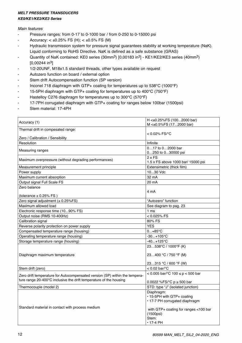
MELT PRESSURE TRANSDUCERSKE0/KE1/KE2/KE3 Series
Main features - Pressure ranges: from 0-17 to 0-1000 bar / from 0-250 to 0-15000 psi- Accuracy: < ±0.25% FS (H); < ±0.5% FS (M)- Hydraulic transmission system for pressure signal guarantees stability at working temperature (NaK). Liquid conforming to RoHS Directive. NaK is defined as a safe substance (GRAS)- Quantity of NaK contained: KE0 series (30mm3) [0,00183 in3] - KE1/KE2/KE3 series (40mm3) [0,00244 in3]- 1/2-20UNF, M18x1.5 standard threads, other types available on request- Autozero function on board / external option- Stem drift Autocompensation function (SP version)- Inconel 718 diaphragm with GTP+ coating for temperatures up to 538°C (1000°F)- 15-5PH diaphragm with GTP+ coating for temperatures up to 400°C (750°F)- Hastelloy C276 diaphragm for temperatures up to 300°C (570°F)- 17-7PH corrugated diaphragm with GTP+ coating for ranges below 100bar (1500psi)- Stem material: 17-4PH
Accuracy (1) H <±0.25%FS (100...2000 bar) M <±0.5%FS (17...2000 bar)
Thermal drift in compesated range:
Zero / Calibration / Sensibility< 0.02% FS/°C
Resolution Infinite
Measuring ranges 0…17 to 0…2000 bar 0…250 to 0...30000 psi
Maximum overpressure (without degrading performances) 2 x FS 1.5 x FS above 1000 bar/ 15000 psi
Measurement principle Extensimetric(thickfilm)Power supply 10...30 VdcMaximum current absorption 32 mAOutput signal Full Scale FS 20 mAZero balance
(tolerance ± 0.25% FS )4 mA
Zero signal adjustment (± 0.25%FS) “Autozero” functionMaximum allowed load See diagram to pag. 23Electronic response time (10...90% FS) 1 msOutput noise (RMS 10-400Hz) < 0.025% FSCalibration signal 80% FSReverse polarity protection on power supply YESCompensated temperature range (housing) 0...+85°COperating temperature range (housing) -30...+105°CStorage temperature range (housing) -40...+125°C
Diaphragm maximum temperature
23…538°C / 1000°F (K)
23…400 °C / 750 °F (M)
23…315 °C / 600 °F (W)Stem drift (zero) < 0.02 bar/°C
Zero drift temperature for Autocompensated version (SP) within the tempera-ture range 20-400°C inclusive the drift temperature of the housing
<0.005bar/°C100≤p<500bar
0.0022%FS/°Cp≥500barThermocouple (model 2) STD: type “J” (isolated junction)
Standard material in contact with process medium
Diaphragm: • 15-5PH with GTP+ coating • 17-7 PH corrugated diaphragm
with GTP+ coating for ranges <100 bar (1500psi) Stem: • 17-4 PH

1380599 MAN_MELT_SIL2_04-2020_ENG
Protection degree (with 6-pole female connector CON300) IP66 (EN 60529)Insulation resistance (at 50Vdc) >1000 Mohm
Electromagnetic compatibility – EmissionEN 61326-1 EN 61326-2-3 EN61326-3-1
Electromagnetic compatibility – ImmunityEN 61326-1 EN 61326-2-3 EN61326-3-1
FS = Full scale output :
(1) BFSL method (Best Fit Straight Line): includes combined
effects of Non-Linearity, Hysteresis and Repeatability (according to IEC 62828-2).Sensors are manufactured in compliance with:
- EMC compatibility directive
- RoHS directive
- Machinery directive ElectricalinstallationrequirementsandConformitycertificateareavailableonourwebsite:www.gefran.com
14 80599 MAN_MELT_SIL2_04-2020_ENG
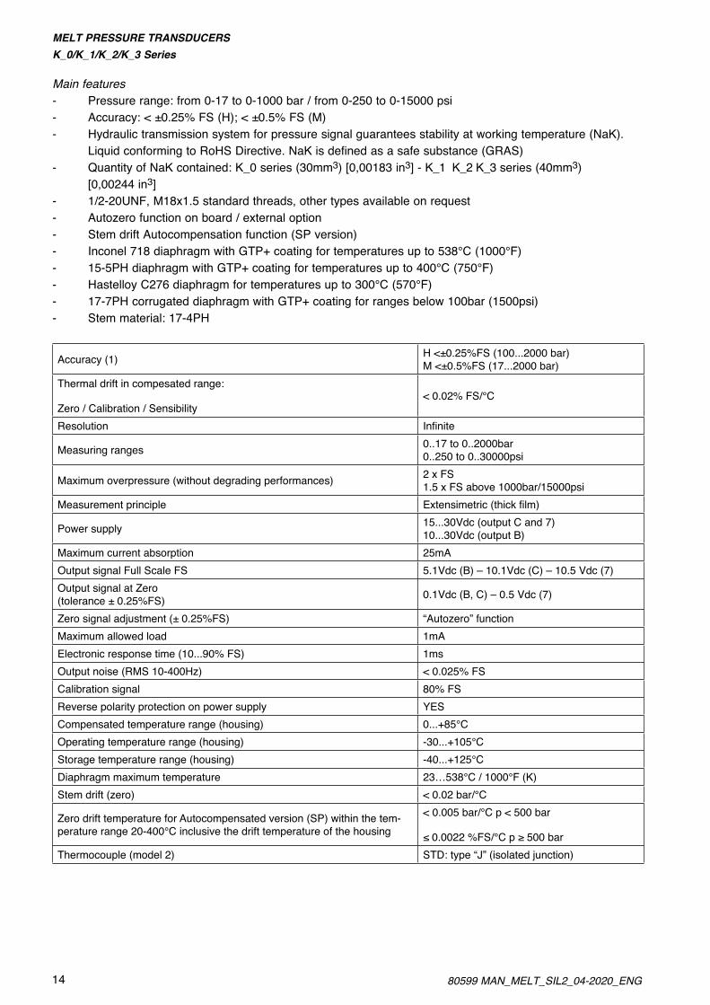
MELT PRESSURE TRANSDUCERSK_0/K_1/K_2/K_3 Series
Main features- Pressure range: from 0-17 to 0-1000 bar / from 0-250 to 0-15000 psi- Accuracy: < ±0.25% FS (H); < ±0.5% FS (M)- Hydraulic transmission system for pressure signal guarantees stability at working temperature (NaK). Liquid conforming to RoHS Directive. NaK is defined as a safe substance (GRAS)- Quantity of NaK contained: K_0 series (30mm3) [0,00183 in3] - K_1 K_2 K_3 series (40mm3) [0,00244 in3]- 1/2-20UNF, M18x1.5 standard threads, other types available on request- Autozero function on board / external option- Stem drift Autocompensation function (SP version)- Inconel 718 diaphragm with GTP+ coating for temperatures up to 538°C (1000°F)- 15-5PH diaphragm with GTP+ coating for temperatures up to 400°C (750°F)- Hastelloy C276 diaphragm for temperatures up to 300°C (570°F)- 17-7PH corrugated diaphragm with GTP+ coating for ranges below 100bar (1500psi)- Stem material: 17-4PH
Accuracy (1) H <±0.25%FS (100...2000 bar) M <±0.5%FS (17...2000 bar)
Thermal drift in compesated range:
Zero / Calibration / Sensibility< 0.02% FS/°C
Resolution Infinite
Measuring ranges 0..17 to 0..2000bar 0..250 to 0..30000psi
Maximum overpressure (without degrading performances) 2 x FS 1.5 x FS above 1000bar/15000psi
Measurement principle Extensimetric(thickfilm)
Power supply 15...30Vdc (output C and 7) 10...30Vdc (output B)
Maximum current absorption 25mAOutput signal Full Scale FS 5.1Vdc (B) – 10.1Vdc (C) – 10.5 Vdc (7)Output signal at Zero (tolerance ± 0.25%FS) 0.1Vdc (B, C) – 0.5 Vdc (7)
Zero signal adjustment (± 0.25%FS) “Autozero” functionMaximum allowed load 1mAElectronic response time (10...90% FS) 1msOutput noise (RMS 10-400Hz) < 0.025% FSCalibration signal 80% FSReverse polarity protection on power supply YESCompensated temperature range (housing) 0...+85°COperating temperature range (housing) -30...+105°CStorage temperature range (housing) -40...+125°CDiaphragm maximum temperature 23…538°C / 1000°F (K)Stem drift (zero) < 0.02 bar/°C
Zero drift temperature for Autocompensated version (SP) within the tem-perature range 20-400°C inclusive the drift temperature of the housing
< 0.005 bar/°C p < 500 bar
≤0.0022%FS/°Cp≥500barThermocouple (model 2) STD: type “J” (isolated junction)

1580599 MAN_MELT_SIL2_04-2020_ENG
Standard material in contact with process medium
Diaphragm: • 15-5PH with GTP+ coating • 17-7 PH corrugated diaphragm
with GTP+ coating for ranges <100 bar (1500psi) Stem: • 17-4 PH
Protection degree (with 6-pole female connector CON300) IP66 (EN 60529)Insulation resistance (at 50Vdc) >1000 Mohm
Electromagnetic compatibility – EmissionEN 61326-1 EN 61326-2-3 EN61326-3-1
Electromagnetic compatibility – ImmunityEN 61326-1 EN 61326-2-3 EN61326-3-1
FS = Full scale output :
(1) BFSL method (Best Fit Straight Line): includes combined
effects of Non-Linearity, Hysteresis and Repeatability (according to IEC 62828-2).Sensors are manufactured in compliance with:
- EMC compatibility directive
- RoHS directive
- Machinery directive ElectricalinstallationrequirementsandConformitycertificateareavailableonourwebsite:www.gefran.com

16 80599 MAN_MELT_SIL2_04-2020_ENG
4. WEIGHT AND MECHANICAL DIMENSIONS
4.1. Weight
Weight for versions standard to catalogue:
M_0 / W_0 / K_0 series 250 gr.M_1 / W_1 / K_1 series 350 gr.M_2 / W_2 / K_2 series 430 gr.M_3 / W_3 / K_3 series 200 gr.
4.2. Specific filling liquid
MERCURY
- Maximum temperature range 400°C- Mercury filling volume for M series model:
ME0 / M_0 30mm3
ME1 / M_1 40mm3
ME2 / M_2 40mm3
ME3 / M_3 40mm3
OIL
- Oil certified FDA (CFR 178.3620 and CFR 172.878)- Maximum temperature range 315°C- Oil filling volume for W series model:
WE0 / W_0 30mm3
WE1 / W_1 40mm3
WE2 / W_2 40mm3
WE3 / W_3 40mm3
NaK
- Sodium and potassium alloy (GRAS)- Maximum temperature range 538°C- NaK volume for K series model:
KE0 / K_0 30mm3
KE1 / K_1 40mm3
KE2 / K_2 40mm3
KE3 / K_3 40mm3
4.3. Mechanical dimensions
See the individual product data sheets for mechanical dimensions.

1780599 MAN_MELT_SIL2_04-2020_ENG
5. INSTALLATION, MOUNTING AND MAINTENANCE
5.1. Instruction and maintenance (Installation hole)
Correct installation of the sensor is essential for good operation and long life.TheMeltsensor’sspeciallocationandthetypeofmaterialinwhichitworksdemandextremecarewhenmounting it in the machine.
Following advice for extending the sensors lifetime: a) Avoid shocks and abrasions to the in contact diaphragm. Protect the transducer with its cover each time you remove it from its seat. b) The seat must be prepared perfectly and with appropriate tools in order to respect the depth and axiality of the holes and tapping. Pay particular attention to the coaxiality of the holes to the thread, because diaxialities greater than 0.2mm will break the transducer during assembly. It is essential that hole depth guarantee the absence of chambers or air pockets in which extrusion material may be trapped. To prevent contact with the extrusion screw or with tools used to clean the extrusion chamber, the front diaphragm must not extend from the inner wall of the extruder. c) Before assembling the transducer in machines already in operation, make sure that the housing is clean. Remove any residual with the suitable cleaning device. d) The transducer should be removed only with the machine empty (without pressure) but still hot. e) The transducer should be cleaned with solvents for the material being processed. Any mechanical action on the contact diaphragm modifies its operation and could break it.
To make this easier, the product is supplied with full documentation on the dimensions of the installation hole and on procedures to be run before using the sensor.An accessory drilling kit is also supplied, for exact copying of transducer rod dimensions.
Drilling kit
A drilling kit with shaped tools for drilling, reaming and tapping is available to facilitate correct preparation of the assembly housing.The assembly housing must be perfect to assure proper transducer function and long life.Drilling kits are available in the following versions: KF12, KF18.
Drilling procedure
- Drill hole (d4) up to a distance from the hole equal to the sum of (a+b+c) (tool 3)- Drill hole (d2) passing with the tip (tool 1)- Create the seal housing at a distance from the hole equal to dimension (a) (tool 4)- With a roughing tap, create threading 1/2-20UNF-2B (recognizable from the greater number of threads beveled at the mouth) (tool 5)- With a finishing tap, go over threading 1/2-20UNF-2B up to a distance from the bottom equal to the sum of (a+b) (tool 6)- Ream hole (d2) with reamer (tool 2).
18 80599 MAN_MELT_SIL2_04-2020_ENG
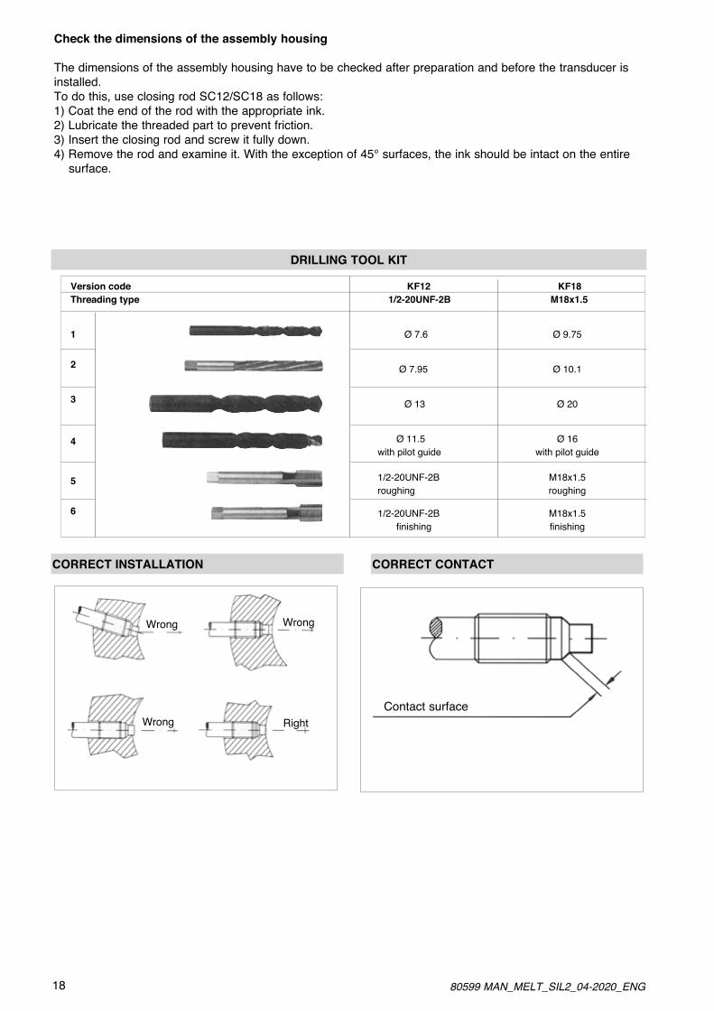
Check the dimensions of the assembly housing
The dimensions of the assembly housing have to be checked after preparation and before the transducer is installed.To do this, use closing rod SC12/SC18 as follows:1) Coat the end of the rod with the appropriate ink.2) Lubricate the threaded part to prevent friction.3) Insert the closing rod and screw it fully down.4) Remove the rod and examine it. With the exception of 45° surfaces, the ink should be intact on the entire surface.
Version code Threading type
1
2
3
4
5
6
Wrong Wrong
Wrong Right
DRILLING TOOL KIT
KF12 KF18 1/2-20UNF-2B M18x1.5
Ø 7.6 Ø 9.75
Ø 7.95 Ø 10.1
Ø 13 Ø 20
Ø 11.5 Ø 16with pilot guide with pilot guide
1/2-20UNF-2B M18x1.5 roughing roughing
1/2-20UNF-2B M18x1.5 finishing finishing
CORRECT INSTALLATION CORRECT CONTACT
Contact surface

1980599 MAN_MELT_SIL2_04-2020_ENG
5.2. Instruction and maintenance (Sensor installation procedure)
Installation procedure
1) Make sure the assembly drilling procedure was done correctly. If you install the sensor in a previously used hole, make sure the hole is completely clean and free of any plastic residue. 2) Remove the protective cap from the sensor point. 3) Lubricate the thread with non-grip grease such as Neverseez (Bostik), or C5A (Felpro), or equivalent.4) Insertthesensorsecurelyintothehole,firstbyhandandthenwithawrench,⁄turnatatime. Recommended torque wrench setting: 50 N-m; maximum: 56.5 N-m.
Calibration procedure
Bring the system to work temperature with the transducer installed and connected to the measurement instru-ment without any pressure applied.The measurement chain connected to the transducer is calibrated as follows:
1) Reset the indication on the instrument to reset the temperature variation zero shift. In the series with amplified output (transmitter), you can use the Autozero function to run the reset.
a) For correct zero resetting, run Autozero only after work temperature has been completely reached.
2) Calibrate the instrument and have it display the calibration value shown on the transducer data plate (80% of full scale).
3) If the instrument does not exactly indicate zero, repeat points 1 and 2. In this way, the instrument is cali- brated t ogive the exact indication in the chosen engineering unit.
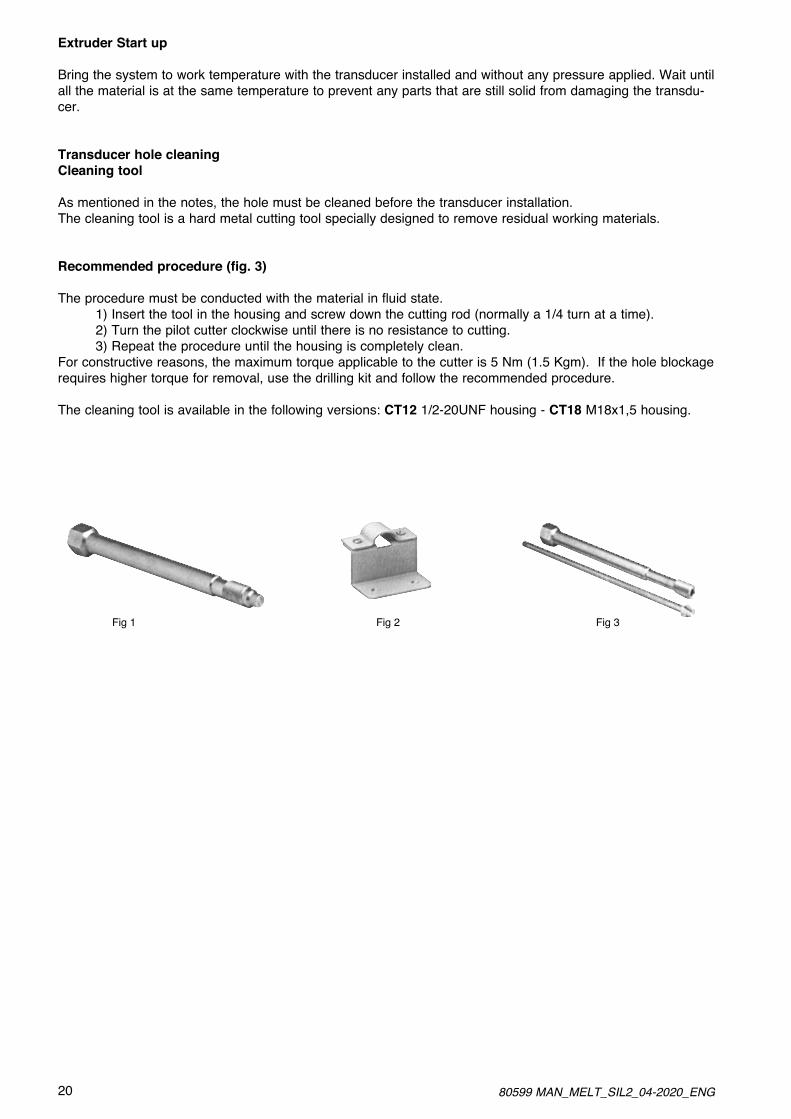
Removal (fig. 1)
To remove the transducer from its housing and continue the procedure, closing rods with identical mechanical dimensions are available. The closing rods differ by type of threading; applicable pressure is 2000bar for all rods. The closing rod is available in the following versions: SC12 1/2-20UNF housing - SC18 M18x1 housing.
Brackets (fig. 2)
Models with flexible sheathing require precise fastening of the protective housing of the measurement point. We recommend bracket (SF18) for fastening. Remember that the fastening point must be vibration-free (vibrations affect the measurement) and that temperatures must not exceed the maximum temperature for the strain gauge housing (as stated on the technical sheet for the transducer).
20 80599 MAN_MELT_SIL2_04-2020_ENG
Extruder Start up
Bring the system to work temperature with the transducer installed and without any pressure applied. Wait until all the material is at the same temperature to prevent any parts that are still solid from damaging the transdu-cer.
Transducer hole cleaningCleaning tool
As mentioned in the notes, the hole must be cleaned before the transducer installation.The cleaning tool is a hard metal cutting tool specially designed to remove residual working materials.
Recommended procedure (fig. 3)
The procedure must be conducted with the material in fluid state. 1) Insert the tool in the housing and screw down the cutting rod (normally a 1/4 turn at a time). 2) Turn the pilot cutter clockwise until there is no resistance to cutting. 3) Repeat the procedure until the housing is completely clean.For constructive reasons, the maximum torque applicable to the cutter is 5 Nm (1.5 Kgm). If the hole blockage requires higher torque for removal, use the drilling kit and follow the recommended procedure.
The cleaning tool is available in the following versions: CT12 1/2-20UNF housing - CT18 M18x1,5 housing.
Fig 2Fig 1 Fig 3

2180599 MAN_MELT_SIL2_04-2020_ENG
5.3. Instruction and maintenance (Mechanical dimensions of transducer / drilling)
D1 1/2-20UNF M10x1.0 M14x1.5 M18x1.5
D2 .307/.305“[7.80/7.75mm]
.236/.234“[5.99/5.94mm
.307/.305“[7.80/7.75mm]
.394/.392“[10.01/9.96mm]
D3 .414/.412“[10.52/10.46mm]
.336/.334“[8.53/8.48mm]
.475/.470“[12.07/111.94mm]
.630/.627“[16.00/15.92mm]
A .219/.209 “[5.56/5.31mm]
.256/.246 “[6.50/6.25mm]
.236/.226 “[5.99/5.74mm]
.236/.226 “[5.99/5.74mm]
B .450“[11.43mm]
.430“[10.92mm]
.480“[12.19mm]
.590“[14.98mm]
C 1.07“[27.2mm]
1.06“[26.9mm]
1.28“[32.5mm]
1.34“[34.0mm]
D1 1/2-20UNF M10x1.0 M14x1.5 M18x1.5
D2 .313 ±0.001”[7.95 ±0.02mm]
.241 ±0.001” [6.12 ±0.02mm]
.319 ±0.001”[8.10 ±0.02mm]
.398 ±0.001”[10.10 ±0.02mm]
D3 .454 ±0.004”[11.53 ±0.1mm]
.344 ±0.004”[8.74 ±0.1mm]
.478 ±0.004”[12.14±0.1mm]
.634 ±0.004”[16.10 ±0.1mm]
D4 .515“ [13mm]min.
.515“ [13mm]min.
.630“ [16mm]min.
.790“ [20mm]min.
A .225“ [5.72mm]min.
.263“ [6.68mm]min.
.240“ [6.10mm]min.
.240“ [6.10mm]min.
B .17“ [4.3mm]max.
.11“ [2.8mm]max.
.16“ [4.0mm]max.
.16“ [4.0mm]max.
C .75” [19mm] .75” [19mm] .75” [19mm] .99” [25mm]
Exposed Capillary Sensor tip Mounting hole dimensions dimensions
D1 1/2-20UNF
D2 .307/.305“[7.80/7.75mm]
D3 .414/.412“[10.52/10.46mm]
A .125/.120 “[3.18/3.05mm]
B .318/.312 “[8.08/7.92mm]
C 81“ [20.6mm]
ATTENTION ! Incorrect working or shape of the hole can result in properties out of specification, bad behavior or damage to the sensor.

22 80599 MAN_MELT_SIL2_04-2020_ENG
6. INSTALLATION AND ELECTRICAL CONNECTIONS
The system must be used only in accordante with the requie protection level.Thesensormustbeprotectedagainstaccidentalknocksandusedinaccordantewiththeinstrument’sambientcharacteristics and performance levels.The sensors must be powered with non-distributed networks and always at lengths of less than 30 mt.In case of outdoor installations, follow the instructions in paragraph 6.5
*In case of safety applications see further limitations in paragraph 10
6.1. General precautions
The interface with SRP/CS (Safety Related Part of a Control System) consists of multi-pole connectors shown in the following figures, which also indicate the connections in the case of amplified voltage output (3 wires) or current output (2 wires: the sensor is placed in series in the current loop); to these connections are added optionally contacts for the execution of external autozero / cal commands.Installation notes
- The transducer must be gronde (normally through the machine body or equipment it is installed on).- Use a shielded cable only. The braiding must be connected to the connector case. The braiding on instrument / PLC side must be left floating.- To prevent interference, separate the power cables from the signal cables.
Standard installation (recommended)
6.2. Electrical installation
Machine Press
Equipment
–Ground
Braiding connected to connector case
Transducer
Rod / Pressure intake
Cable connector
Shielded cable
Floating braiding
PLC / Instrument

2380599 MAN_MELT_SIL2_04-2020_ENG
Electrical connections
The diagram shows the optimum ratio between load and power supply for transmitters with 4…20mA output.For correct function, use a combination of load resistance and voltage that falls within the shaded area
24 80599 MAN_MELT_SIL2_04-2020_ENG
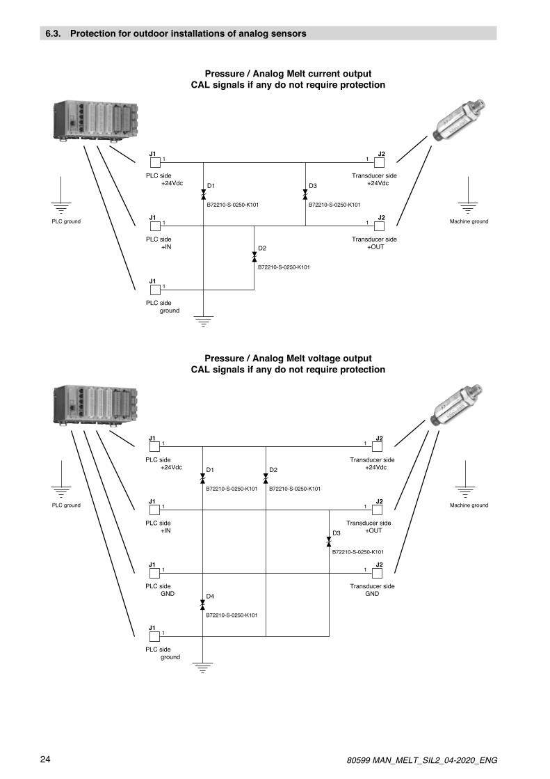
6.3. Protection for outdoor installations of analog sensors
Pressure / Analog Melt current outputCAL signals if any do not require protection
J1
J1
J1
+24Vdc
+IN
D1 D3
J2
J2
+24Vdc
+OUT
B72210-S-0250-K101B72210-S-0250-K101
1
1
1
1
1
D2
B72210-S-0250-K101
PLC side
PLC side
PLC side ground
Transducer side
Transducer side
PLC ground Machine ground
Pressure / Analog Melt voltage outputCAL signals if any do not require protection
J1
J1
J1
J1
+24Vdc
+IN
GND D4
D1 D2
D3
J2
J2
J2
+24Vdc
+OUT
GND
B72210-S-0250-K101
B72210-S-0250-K101
B72210-S-0250-K101B72210-S-0250-K101
1
1
1
1
1
1
1
PLC side
PLC side
PLC side
PLC side ground
Transducer side
Transducer side
Transducer side
PLC ground Machine ground

2580599 MAN_MELT_SIL2_04-2020_ENG
6.4. Standard reference
Gefran products, described in this manual, are compliant to the European Directive 2014/30/EU.They are tested according to the standard EN 61326-1 “Electrical equipment for measurement, control and labo-ratory use - EMC requirements”, Part 1 “general requirements and EN 61326-2-3 “Electrical equipment for mea-surement, control and laboratory use - EMC requirements”, Part 2-3: Particular requirements - Test configuration, operational conditions and performance criteria for transducers with integrated or remote signal conditioning.
NoteIn accordance with IEC/EN 62061 and IEC/EN 61508, transducers of the M, W, K SIL2 series also comply with EN 61326-3-1 “Electrical equipment for measurement, control, and laboratory use - immunity requirements for safety-related systems and for equipment intended to perform safety-related functions (functional safety) - General industrial applications”.
6.5. EMC and RoHS Requisites
Gefran Melt transducers and transmitters are built in conformity with the following EMC directives: EMC 2014/30/EU and RoHS 2011/65/EU.

26 80599 MAN_MELT_SIL2_04-2020_ENG
7. ON-BOARD FUNCTION
AUTOZERO All signal variations in the absence of pressure can be eliminated by using the Autozero function.The function is activated by closing a magnetic contact located in the transmitter housing (function cannot be activated when machine is in operation).The device used for the reset control is a magnet located on the outside of the housing, attached to it by a pla-stic support. This system provides total reliability and easy use.On sensors configured in a dedicated manner, the Autozero function can be activated externally by short-circu-iting pins E and F on the connector.By using the reset control, setting the Zero signal with a trimmer becomes obsolete; the same is true for the Span signal, for which the sensor can be recalibrated via software
1: machine pressure = 0 bar and transdu cer powered 2: put magnetic pointer on marked spot (1…10sec) 3: remove magnetic pointer 4: ready !
Magnetic pointer 1.0,10 sec remove marked spot
ACTIVATION OF AUTOZERO AFTER THE FIRST INSTALLATIONThe Autozero function makes it much easier to run calibrations after the first installation.With the sensor installed and with the extruder at work temperature, wait 1 minute before running Autozero.This delay is requie to allow the system temperature to stabilize.If the transmitter is kept powered, additional Autozero activations can ber un immediately; on the other hand, you will have to wait 1 minute each time the system is switched on again.
AUTOZERO FUNCTION
Application mode Limits ResultThe Autozero function is activated by:1) positioning the magnet near the Autozero label on the shell of the sensor.2) Short-circuiting the pin E-F (external Autozero version).The magnet has to be maintained onthe Autozero position for a time within1 to 10 sec.
The whole Zero unbalancement incomparison to the zero done by themanufacturer, has to be ± 10% FS (*)
The Autozero effect will be visible afterwaiting 2 sec after the start of thefunction.The precision of the zero value will bedefinedbytheaccuracyclassofthesensor.TheAutozerofunctiondoesn’tworkoutsidethedefinedlimits.
NOTE:(*): This value has to be considered typical. Higher limits value will be allowed for different range.During the Autozero phase, the current output for the ME/WE transmitter series, will increase around 7mA.That’sashortvariationonlyvisibleduringtheAutozerophase;itwon’thaveanyeffectsonthefinalsignal.
7.1. Autozero function
The ON BOARD functions are command modes available to the user only for the purpose of periodic recalibra-tion of the system in the process and can be operated in two ways:√CALpin√Magneticsensor

2780599 MAN_MELT_SIL2_04-2020_ENG
Fine-Autozero Procedure
Application mode Limits ResultThe Fine-Autozero function is activa-ted by:1) positioning the magnet near theAutozero label on the shell of thesensor.2) Short-circuiting the pin E-F (exter-nal Autozero version).The magnet has to be maintained onthe Autozero position for a time within10 to 30 sec.After removing the magnet the signalwill start changing the value step bystep.Stop adjustment: touch the Autozeroarea with the magnet to stop the signal variation.
The whole Zero unbalancement incomparison to the zero done by themanufacturer, has to be ± 10% FS (*).
The output signal will change within a±100mV value (±0,16mA for out 4-20mA) the change decreases in step of 6mV(12uA for 4-20mA output).
Ex:0..-6..-12..//-100..+100..+94..+88..0
The signal will be stopped withoutdelay once the Autozero area istouched with the magnet.
TheFine-Autozerofunctiondoesn’tworkoutsidethedefinedlimits.
NOTE:(*): this value has to be considered typical. Higher limits value will be allowed for different range- The step duration time is 1 sec- During the Autozero phase, the current output for the ME/WE transmitter series, will increase to around 7mA. Furthermore between the step variations it will be possible to have short overcurrent up to 7mA.-That’sanimmediatevariationonlyvisibleduringtheAutozerophase;itwon’thaveanyeffectsonthefinalsignal.
7.2. Fine-Autozero function
Calibration procedure
Application mode Limits ResultStart cal:The Calibration function is activated by short-circuiting the pin E - F for aminimum time of 1 sec
Stop cal:Release the E - F short-circuit
The whole Zero unbalancement incomparison to the zero done by themanufacturer, has to be ± 20%FS.
During the Calibration phase the signal will be unbalanced to the 80% FS.The calibration effect is visible 2 secafter short-circuiting E - F.TheCalibrationfunctiondoesn’tworkoutsidethedefinedlimits.
NOTE:- During the Calibration phase, the current output for the transmitter, will increase around 7mA.That’sanimmediatevariationonlyvisibleduringtheCalibrationphase;itwon’thaveanyeffectsonthe final signal.- Switching off the supply while the calibration function is activated, could be cause of calibration problems; the transmitter can be recalibrated to the initial value by activating the “partial reset function”.- The Calibration function is not allowed for “external Autozero” version.
7.3. Calibration function
28 80599 MAN_MELT_SIL2_04-2020_ENG
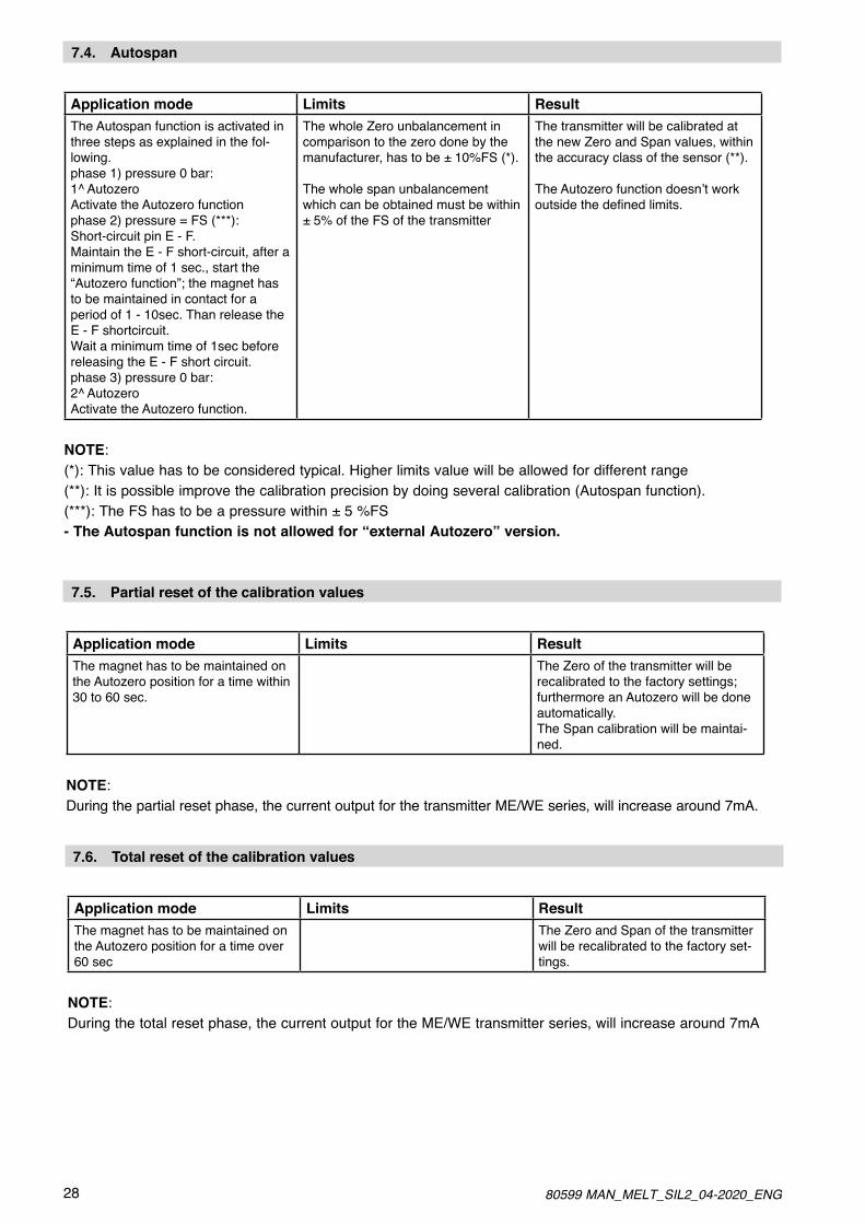
Application mode Limits ResultThe Autospan function is activated inthree steps as explained in the fol-lowing.phase 1) pressure 0 bar:1^ AutozeroActivate the Autozero functionphase 2) pressure = FS (***):Short-circuit pin E - F.Maintain the E - F short-circuit, after aminimum time of 1 sec., start the“Autozero function”; the magnet has to be maintained in contact for a period of 1 - 10sec. Than release the E - F shortcircuit. Wait a minimum time of 1sec before releasing the E - F short circuit.phase 3) pressure 0 bar:2^ AutozeroActivate the Autozero function.
The whole Zero unbalancement incomparison to the zero done by themanufacturer, has to be ± 10%FS (*).
The whole span unbalancement which can be obtained must be within ± 5% of the FS of the transmitter
The transmitter will be calibrated at the new Zero and Span values, within the accuracy class of the sensor (**).
TheAutozerofunctiondoesn’tworkoutsidethedefinedlimits.
NOTE:(*): This value has to be considered typical. Higher limits value will be allowed for different range(**): It is possible improve the calibration precision by doing several calibration (Autospan function).(***): The FS has to be a pressure within ± 5 %FS- The Autospan function is not allowed for “external Autozero” version.
7.4. Autospan
Application mode Limits ResultThe magnet has to be maintained onthe Autozero position for a time within30 to 60 sec.
The Zero of the transmitter will berecalibrated to the factory settings;furthermore an Autozero will be doneautomatically. The Span calibration will be maintai-ned.
NOTE:During the partial reset phase, the current output for the transmitter ME/WE series, will increase around 7mA.
7.5. Partial reset of the calibration values
Application mode Limits ResultThe magnet has to be maintained onthe Autozero position for a time over60 sec
The Zero and Span of the transmitterwill be recalibrated to the factory set-tings.
NOTE:During the total reset phase, the current output for the ME/WE transmitter series, will increase around 7mA
7.6. Total reset of the calibration values

2980599 MAN_MELT_SIL2_04-2020_ENG
8. AUTOCOMPENSATION FUNCTIONAutocompensation of temperature drift
All sensors that use filled technology (i.e., that contain a pressure signal retransmission fluid) share the pro-blem of fluid expansion at working temperature.A negative consequence of expansion is the generation of pressure inside the sensor.The transduction element senses this pressure as a pressure variation in the process, so the reading is affected by an error that averages about 2-4bar/100°C.Thanks to “Autocompensation,” both drifts can be reduced until becoming practically negligible.Fig. 2 shows the degrees of read error achieved, comparing a standard series M sensor to another in the same series but in SP configuration.The graph shows that for a sensor with pressure range of 200 bar, the maximum read error is 0.003 bar/°C, meaning 1bar at 300°C, compared to 8 bar for an equivalent 2 00 bar sensor in standard version.This result was achieved thanks to a temperature read system that reaches the “important” points of the sen-sor and constantly monitors every minimum temperature variation on board.These signals are then transferred to the various stages of conditioning of the electronics until reaching themicroprocessor, which performs compensation of the drift errors introduced.Even the time in which the signal is corrected has been calculated to reduce the effects of temperature transi-tion to a minimum.This means that the values stated in specifications are always respected for every step of the process.
By means of a thermocouple in the signal stem compensated digitaly
8.1. Output signal trend as a function of temperature effect
Or written in table100<p<500 ----> 0,003bar/°C p>500 ----> 0,0014% FS./°C
Thermal drift coefficient (bar/100°C)
Ther
mal
drif
t coe
ffici
ent
(bar
/100
°C)
FS (bar)
30 80599 MAN_MELT_SIL2_04-2020_ENG
9. MAINTENANCE
Melt pressure sensors must be installed and electrically connected by trained people, following all applicable recommendations, with zero pressure and voltage, and with the machine switched off.The sensor must be removed with the plastic in Melt state and the machine in hot conditions.Always remove the sensor before cleaning the machine, using steel brushes or similar tools.Always wear protective gloves and always take adequate ESD precautions to prevent electrostatic discharges that could damage the sensor.Always use the wrench for the hexagonal nut when installing and removing the sensor.DO NOT force the electronics housing.Once the sensor is removed, clean it gently with a soft cloth while the material is still malleable.
9.1. Maintenance
Melt sensors are made with “Filled” technology and contain a pressure transmission fluid.Low-compression fluids such as diathermic oil (FDA and USDA approved), NaK (GRAS substance) for food or medical applications, or mercury are used.Fluid volumes depend on the mechanical structure of the sensor, and leaks can occur only if the contact diaphragm is broken.Any other type of break will not cause emissions to the environment.Never transport or store the sensors without the protective cap and without the original packaging.In particular, as mercury is a hazardous material it must be disposed of in compliance with applicable law.Gefran accepts its Melt sensors (defective or damaged by use) for disposal.
9.2. Transport, storage and disposal

3180599 MAN_MELT_SIL2_04-2020_ENG
10. SAFETY
In case of contact or inhalation of the fluid contained in the Melt sensor, follow the instructions on the toxico-logy sheet for the related substance.In particular, K series Melt sensors use NaK as filling fluid.NaK, composed of Sodium and Potassium (22 Na / 78 K), is an eutectic alloy (i.e., a mixture of two or more substances with a lower melting point than that of its single components) with low compressibility and excellent resistance to high temperatures (up to 538°C).Above all, it is a non-toxic liquid metal that is recognized as GRAS (Generally Regarded As Safe).This allows K series Melt sensors to work in contact with materials used for foods (wrapping films, beverage containers, etc.) or for pharmaceuticals/cosmetics (drug containers, soaps, etc.).In addition, it is totally compatible with the European RoHs (Restriction of Hazardous Substances) Directive with regard to electrical and electronic equipment.If the contact diaphragm breaks due to the application, NaK tends to oxidize or to react with the contact medium (especially in the presence of water or dampness) by an exothermic reaction.This generates a spark which, due to the scarcity of material contained (from 20 to 40mm3 on the average), can last few seconds (maximum of 5).
32 80599 MAN_MELT_SIL2_04-2020_ENG
Hg TOXICOLOGICAL SHEET1 Elements identifying substance or preparation and company
· Product data· Molecular formula: Hg· Structura formula: Hg· Commercial name: Mercury· SDS No: CH0349· Information supplied by: E.S. & Q. A.
5 Fire prevention measures•Approvedfireextinguishers:CO2,powderornebulizedwater.Extinguishlargefireswith nebulized water or alcohol-resistant foam.•Specificrisksduetothesubstances,itscombustionproducts,orreleasedgases:Ifheatedorincaseoffire,theproductmay generate toxic fumes. Fumes contain metal oxides.•Specificmeansofprotection: Wear an all-service mask in closed rooms.
2 Composition/information on ingredients· Chemical characteristics: CAS number 7439-97-6 mercury·Identificationnumber/s· EINECS number: 2311067· CEE number: 080-001-00-0
6 Measures in case of accidental spill• Measures to protect people: In case of vapors/dust/aerosol, use respiratory protections• Measures to protect environment:Incaseofinfiltrationinbodiesofwaterorsewers,notifythe competent authorities.Preventfiltrationinsewers/surfacewaters/groundwater.• Cleaning/absorption methods: Aspirate liquid in suitable container and absorb the rest with porous material (tripoli, acid binder, universal binder, etc.) Dispose of contaminated material in conformity to point 13. Ventilate the area completely.
3 Indication of hazards•Classificationofhazard: T Toxic N Hazardous for the environment
•Indicationsofspecifichazardsforhumansandtheenvironment: R 23 Toxic if inhaled R 33 Danger of cumulative effects R 50/53 Highly toxic for sea life, may cause long-term negative effects on the aquatic environment.
7 Handling and storageHandling• Instructions for safe handling: Keep containers hermetically sealed. Good ventilation/aspiration in workplaces. Open and handle containers with care. Avoid formation of aerosol.•Instructionsforpreventingfiresandexplosions: Keep all-service mask handyStorage•Requirementsforwarehousesandcontainers:Providefloor tank without discharge.· Instructions for mixed storage: not necessary.· Additional instructions regarding storage conditions: Keep containers hermetically sealed.· Storage class:· Class VbF (ordinance regarding combustible substances): Not applicable.
4 First aid• General instructions: Immediately remove clothing contaminated with product. Remove protective mask only after removing contaminated clothing.Incaseofirregularbreathingorbreathingfailure,applyartificial respiration.• Inhalation: Take the victim to a well-ventilated area and administer oxygen. CALL A DOCTOR. If the victim has fainted, try to keep him in a stable position on his side as you move him.• Contact with skin: Wash immediately with soap and water, rinse thoroughly.• Contact with eyes: Wash will running water for several minutes, keeping the eyelids wide open. CALL A DOCTOR.:• Ingestion: Call a doctor if victim feels ill.
8 Exposure control/personal protection• Additional instructions regarding structure of technical systems: No additional data. See point 7· Component whose limits must be kept under control in workplaces: Mercury TLV: 0,025 mg/m3
· Additional instructions: Lists valid on the date of compilation were used as basis· Means of personal protection:· General rules for protection and hygiene at the workplace: Keep away from food, drink, and forage. Immediately remove contaminated clothing. Wash hands before taking a break and at end of shift. Store protective gear separately.· Protective mask: Use the mask in case of brief, slight exposure; for heavier and longer exposure, wear a self-contained breathing apparatus. Use all-service mask only in case of formation of aerosol or mist.· Protective gloves: Neoprene gloves· Goggles: Wear goggles while pouring..
3380599 MAN_MELT_SIL2_04-2020_ENG
Hg TOXICOLOGICAL SHEET 9 Physical and chemical properties· Molecular weight: 200,59 g· Form: Liquid· Color: Silver· Odor: None· Unit value/Method:· Change of state· Melting temperature: -38,86°C· Boiling temperature: 356,73°C· Flash point: not applicable· Danger of explosion: product not explosive· Vapor voltage: a 20°C 0,00163 hPa· Density: a 20°C 13,54 g/cm3
· Solubility in/Mixability with water: slightly and/or not mixable· Organic solvents: insoluble
12 Ecological information· Behavior in ecological context:· Mobility and potential of bioaccumulation: possible biomethylation· Toxic effects on environment: Aquatic toxicity: Mercury LC50 aq.: (Hg++ 96h) 0,06 mg/l (daphnia)· Additional information: Hazard for class 3 waters (WGK German) (Classif. on lists): very hazardous. Do not put in groundwater, rivers, or sewers, even in small doses. Hazard for drinking water even in case of minimum leaks of product in subsoil.Toxicforfishandplankton.
10 Stability and reactivity· Thermal decomposition/conditions to be avoided: the product does not decompose if correctly used.· Substances to be avoided: acetylene· Hazardous reactions: Reactions with peroxides and other substances forming radicals. Decomposition of hydrogen peroxide.· Hazardous products of decomposition: No hazardous products of decomposition are known
13 Information on disposal· Product:· Recommendations: Do not dispose of the product together with domestic waste. Do not put in sewers. Recycle if possible; other wise, contact a company authorized to dispose of indu- strial waste.· Soiled packing:· Recommendations: Dispose of in conformity to government regulations.Washwithwatertobepurifiedanddisposedof.
11 Toxicological information· Acute toxicity:SignificantLD/LC50valuesforclassification: Mercury. For inhalation: LCLo: (30h) 0,03 mg/l (rabbit)· Primary irritability: - on the skin: has no irritating effects. - in the eyes: not particularly irritating. Sensitization: no sensitizing effects are known· Subacute to chronic toxicity: Cumulative effects in case of repeated exposure.
14 Information on transportRoad/rail transport ADR/RID (beyond border)· ADR/RID-GGVS/E class: 8 corrosive substances· Number/letter: 66c· Kemler number: 80· ONU number: 2809· Description of brand: 2809 MercurySea transport IMDG· IMDG class: 8· Page: 8191· ONU number: 2809· Packing group: III· EMS number: 8-12· MFAG: -· Exact technical name: MercuryAir transport ICAO-TI and IATA-DGR· ICAO/IATA class: 8· ONU/ID number: 2809· Packing group: III· Exact technical name: Mercury
34 80599 MAN_MELT_SIL2_04-2020_ENG
Hg TOXICOLOGICAL SHEET15 Information on regulations•ClassificationaccordingtoCEdirectives:TheproductisclassifiedandcodedinconformitytoCEdirectives / rules on hazardous products / dir. 67/548 25° updat e / dir. 88/379 4° update• Label code for product hazardousness: T Toxic N Hazardous for the environment•Natureofspecificrisks(Rphrases): 23 Toxic if inhaled 33 Danger of cumulative effects 50/53 Highly toxic for aquatic organisms, may cause long-term negative effects on the aquatic environment. • Recommendations of prudence (S phrases): 7 Keep container completely closed 45 In case of accident or malaise, call a doctor immedia- tely (if possible, show him/her the label) 60 This material and its container must be disposed of as hazardous waste 61 Dispose of properly. See the special instructions / data sheet on safety• National regulations•ClassificationaccordingtoVbF:Notapplicable.• Class of hazardousness for waters: Hazard for class 3 waters (WGK3) (Classif. on lists): very hazardousAdditional regulations, limitations and prohibitive decrees:Maximum concentration in waste water (DPR 319/76 - Merli Law): 0,005 mg/l
16 Other informationThe above data are based on our current knowledge. Nevertheless, they do not represent any guarantee of product characteristics and are not the basis for any legal and/or contractual relationship.• Data sheet issued by: E.S. & Q. A.• Contact: Emergency Ph. 0039 2 95231• Bibliographic references:ECDIN (Environmental Chem. Data and Information Network)IUCLID (International Uniform Chemical Information Database)NIOSH – Registri of Toxic Effects of Chemical Substan-ces Roth – Wassergefährdende Stoffe Verschueren – Handbook of Environmental Data on Organic Chemi-cals ChemDAT – Safety Data Sheets from E.Merck on CD-ROM Merian – Metals and their compounds in the environment.

3580599 MAN_MELT_SIL2_04-2020_ENG
11. SAFETY NOTES
11.1. ApplicationThe pressure sensors M, W, K SIL2 perform the following safety function:
The safety function performed by the sensor is the correct transduction of the pressure in order to detect over-pressuresinthechamberitself.Thetransductionisintendedascorrectwhenitiswithinthedeclaredspecifica-tions.
The SIL parameters of the transducer are shown in the table below:
Parameter Value Measuring UnitArchitecture 1oo1 --HFT 0 --
βFactors0,05
(when using the product in 1oo2 architecture) --
λDD
Current output
Voltage output
7,83E-07
7,83E-07
1/h
1/hλDU
Current output
Voltage output
1,51E-07
1,51E-07
1/h
1/hSFF
Current output
Voltage output
93,70
93,66
%
%PFH
Current output
Voltage output
1,51E-07
1,51E-07
1/h
1/hSILCL (IEC 62061)
SIL (IEC 61508)2 --
Life time 20 y
The pressure sensors of the M, W, K SIL2 series can be part of a pressure detection system which, when a thresh-old value is exceeded, deactivates all the pressure generation elements through the control system.
Thediagraminthefigureshowsapossibleapplication:thesensordetectsthepressureandconvertsitintoananalogue electrical signal proportional to the value of the measurand; the SRP/CS compares the signal with that set as alarm threshold: if the threshold is exceeded, it deactivates the pressure generation elements.
VOLTAGE OUTPUT
36 80599 MAN_MELT_SIL2_04-2020_ENG
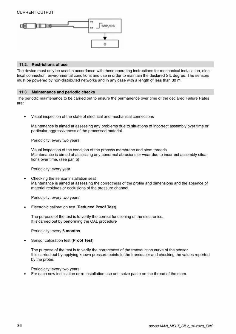
CURRENT OUTPUT
11.2. Restrictions of useThe device must only be used in accordance with these operating instructions for mechanical installation, elec-trical connection, environmental conditions and use in order to maintain the declared SIL degree. The sensors must be powered by non-distributed networks and in any case with a length of less than 30 m.
11.3. Maintenance and periodic checksThe periodic maintenance to be carried out to ensure the permanence over time of the declared Failure Rates are:
• Visual inspection of the state of electrical and mechanical connections
Maintenance is aimed at assessing any problems due to situations of incorrect assembly over time or particular aggressiveness of the processed material.
Periodicity: every two years
Visual inspection of the condition of the process membrane and stem threads.Maintenance is aimed at assessing any abnormal abrasions or wear due to incorrect assembly situa-tions over time. (see par. 5)
Periodicity: every year
• Checking the sensor installation seatMaintenanceisaimedatassessingthecorrectnessoftheprofileanddimensionsandtheabsenceofmaterial residues or occlusions of the pressure channel.
Periodicity: every two years.
• Electronic calibration test (Reduced Proof Test)
The purpose of the test is to verify the correct functioning of the electronics.It is carried out by performing the CAL procedure
Periodicity: every 6 months
• Sensor calibration test (Proof Test)
The purpose of the test is to verify the correctness of the transduction curve of the sensor.It is carried out by applying known pressure points to the transducer and checking the values reported by the probe.
Periodicity: every two years• For each new installation or re-installation use anti-seize paste on the thread of the stem.
3780599 MAN_MELT_SIL2_04-2020_ENG
11.4. Mean Time to Restoration The MTTR (mean time of restoration) is calculated considering travel time, device location, maintenance contracts, environmental restrictions, warehouses and the technical time of replacement of the device (not its repairing).
In particular in the MTTR is included:
• The time required to replace and reset the device
• Travel time and any maintenance contracts
The MTTR calculation does NOT include:
• Any administrative delays on the part of the end user
• The unavailability of spare parts
Under these conditions the MTTR will be equal to 5 working days.
Considering instead only the technical time for replacement and restoration of the device (i.e. the spare part is already available from the user) the MTTR is equal to approx. 4h
11.5. Indication on response timesThe response time to pressure transduction is 1 ms
11.6. Effects on the safety function of deviations in performanceThe limit of acceptability in deviations of metrological performance in order not to induce loss of the safety func-tion is ± 5 % of the value of span at room temperature.
11.7. Inhibition and suspension of the safety functionWith the M, W, K SIL2 series sensors, it is not possible to bypass the safety function of the designated category.
Any inhibition of the safety function is at the charge (and responsibility) of the machine manufacturer.
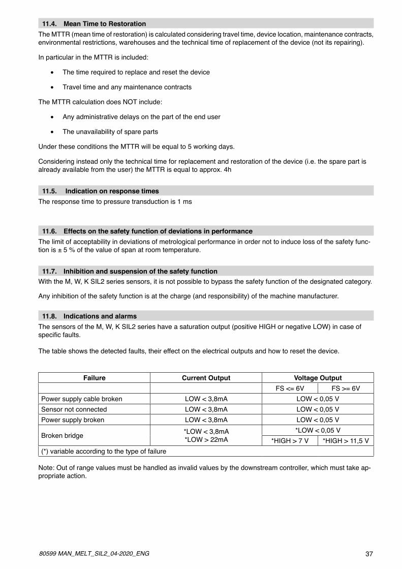
11.8. Indications and alarmsThe sensors of the M, W, K SIL2 series have a saturation output (positive HIGH or negative LOW) in case of specificfaults.
The table shows the detected faults, their effect on the electrical outputs and how to reset the device.
Failure Current Output Voltage Output
FS <= 6V FS >= 6VPower supply cable broken LOW < 3,8mA LOW < 0,05 VSensor not connected LOW < 3,8mA LOW < 0,05 VPower supply broken LOW < 3,8mA LOW < 0,05 V
Broken bridge *LOW < 3,8mA*LOW > 22mA
*LOW < 0,05 V*HIGH > 7 V *HIGH > 11,5 V
(*) variable according to the type of failure
Note: Out of range values must be handled as invalid values by the downstream controller, which must take ap-propriate action.

38 80599 MAN_MELT_SIL2_04-2020_ENG
All Gefran sensors are built in conformity to UNI EN ISO 9001: 2000In case of malfunction, you can run a series of simple checks to identify the type of fault. If the problem is cau-sed by a sensor malfunction, the sensor MUST be returned to Gefran. Only Gefran personnel are permitted to open the sensor.AnyrepairattemptedwithoutGefran’sauthorizationwillcausethewarranteeexpiry.
ELECTROMECHANICAL PROBLEMS
MALFUNCTION POSSIBLE CAUSE POSSIBLE SOLUTION
NO SIGNAL NO POWER SUPPLY CONNECTION FAILED
CHECK POWER SUPPLT / CONNECTIONS
NO SIGNAL VARIATION BROKEN DIAPHRAGM PLUG FORMED
CHECK HOUSING AND DIAPHRAGM
EXCESSIVE SIGNAL IMBALANCEOVERPRESSUREELECTRONICS MALFUNCTION CALIBRATION ON
CHECK CALIBRATION
SIGNAL VARIATION AT TIGHTENING INCORRECT INSTALLATION POINT CHECK INSTALLATION HOLE
NO TEMPERATURE READ (SERIES 2)
BROKEN THERMOCOUPLE BROKEN TC WIRE CHECK CONTINUITY
12. RESOLUTION PROBLEMS
3980599 MAN_MELT_SIL2_04-2020_ENG
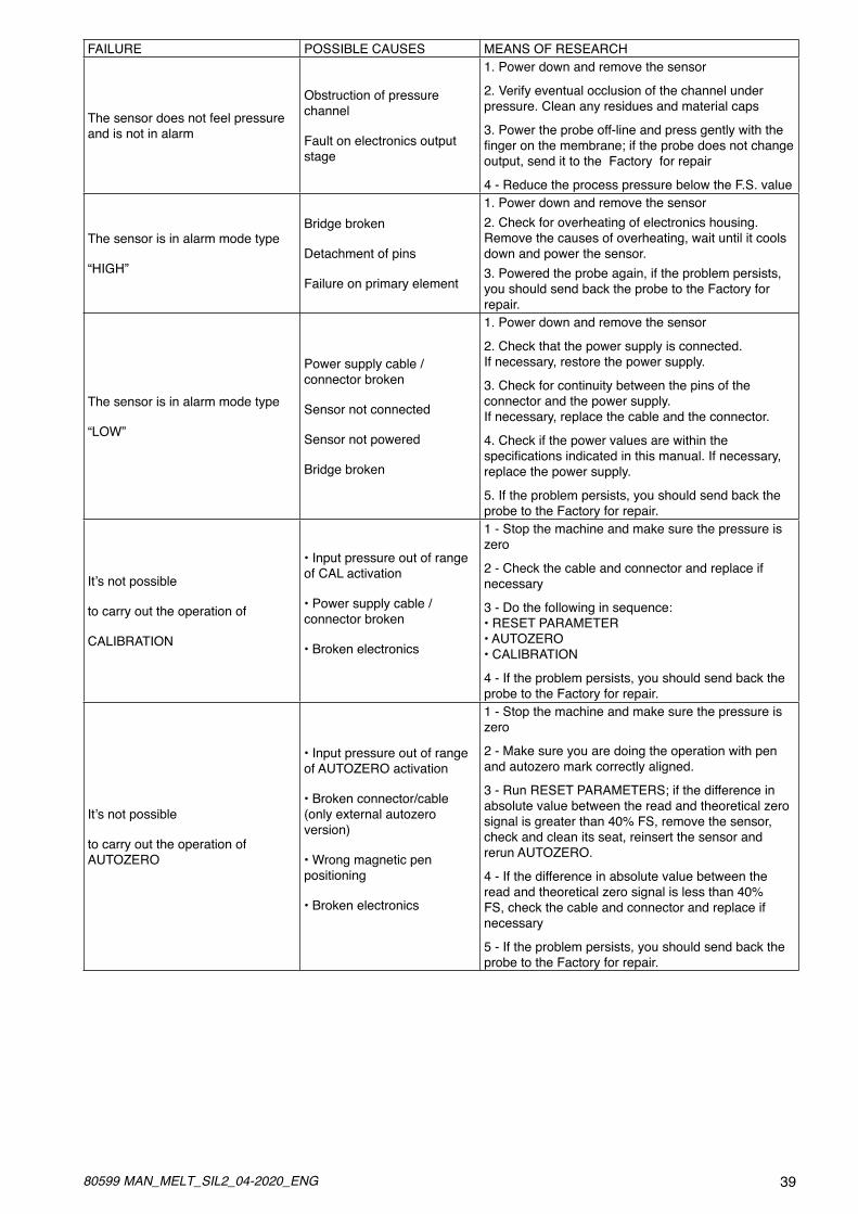
FAILURE POSSIBLE CAUSES MEANS OF RESEARCH
The sensor does not feel pressure and is not in alarm
Obstruction of pressure channel
Fault on electronics output stage
1. Power down and remove the sensor
2. Verify eventual occlusion of the channel under pressure. Clean any residues and material caps
3. Power the probe off-line and press gently with the fingeronthemembrane;iftheprobedoesnotchangeoutput, send it to the Factory for repair
4 - Reduce the process pressure below the F.S. value
The sensor is in alarm mode type
“HIGH”
Bridge broken
Detachment of pins
Failure on primary element
1. Power down and remove the sensor 2. Check for overheating of electronics housing. Remove the causes of overheating, wait until it cools down and power the sensor.3. Powered the probe again, if the problem persists, you should send back the probe to the Factory for repair.
The sensor is in alarm mode type
“LOW”
Power supply cable /connector broken
Sensor not connected
Sensor not powered
Bridge broken
1. Power down and remove the sensor
2. Check that the power supply is connected. If necessary, restore the power supply.
3. Check for continuity between the pins of the connector and the power supply. If necessary, replace the cable and the connector.
4. Check if the power values are within the specificationsindicatedinthismanual.Ifnecessary,replace the power supply.
5. If the problem persists, you should send back the probe to the Factory for repair.
It’snotpossible
to carry out the operation of
CALIBRATION
• Input pressure out of range of CAL activation
• Power supply cable /connector broken
• Broken electronics
1 - Stop the machine and make sure the pressure is zero
2 - Check the cable and connector and replace if necessary
3 - Do the following in sequence: • RESET PARAMETER • AUTOZERO • CALIBRATION
4 - If the problem persists, you should send back the probe to the Factory for repair.
It’snotpossible
to carry out the operation of AUTOZERO
• Input pressure out of range of AUTOZERO activation
• Broken connector/cable (only external autozero version)
• Wrong magnetic pen positioning
• Broken electronics
1 - Stop the machine and make sure the pressure is zero
2 - Make sure you are doing the operation with pen and autozero mark correctly aligned.
3 - Run RESET PARAMETERS; if the difference in absolute value between the read and theoretical zero signal is greater than 40% FS, remove the sensor, check and clean its seat, reinsert the sensor and rerun AUTOZERO.
4 - If the difference in absolute value between the read and theoretical zero signal is less than 40% FS, check the cable and connector and replace if necessary
5 - If the problem persists, you should send back the probe to the Factory for repair.
40 80599 MAN_MELT_SIL2_04-2020_ENG
13. APPENDIX A: OPERATING PRINCIPLE
Filled-technology Melt sensor
The Melt probe is a pressure sensor that resists high temperatures. As can be seen on the diagram, the entire structure is built to transfer the pressure of the medium to the transducer part while keeping the transdu-cer as far as possible from the heat source. The hydraulic circuit built for this purpose consists of a tip with 0.1 mm inner diameter, at the ends of which are welded the contact diaphragm and the strain gauge diaphragm. The sensor is filled with a liquid with low compression coefficient (mercury or FDA-approved oil for food applications) to transfer strain. For both versions, the amount of liquid depends on sensor design: the rigid rod contains 30mm3, while flex versions contain 40mm3. All parts have to be sized in accordance with the strains to which the system is subjected: pressures up to 2000 bar and work temperatures up to 400°C. The Melt probe must be subjected to a “static” type of strain; “dynamic” applications compromise the pro-duct’sreliability. In addition to a guarantee of long life, the sensor is built to guarantee reliable reads in line with the accu-racy specifications stated in the technical data for every condition of use described in the instruction manual. The diaphragm geometries are designed on the basis of volumes and pressures occurring during mea-surement. In essence, the pressure that the medium exerts on the contact diaphragm must generate a precise deformation of the measurement diaphragm. The measurement element (called strain gauge), which translates the physical quantity (pressure) in to an electrical signal, is glued to the measurement diaphragm.
13.1. Mechanical construction and operation
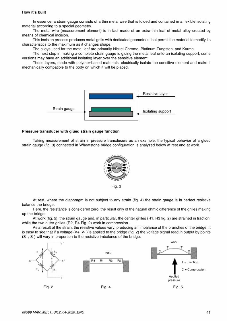
Melt pressure sensors with glued strain gauge function
By for the most popular system for measuring the deformation of materials, the strain gauge is used indu-strially to measure the elongation of metals, especially steel and aluminum. Its versatility, reliability, and high accuracy in transducing the measured physical quantity makes this is one of the most often used technologies for building pressure sensors. Thanks to years of experience in building sensors, Gefran offers a wide variety of products using strain gauge technology, including industrial and Melt pressure transducers. By continuously developing and refining this technology, Gefran creates sensors with unbeatable perfor-mance.
Definition of strain gauge
The strain gauge is a device that transduces a physical quantity into an electrical quantity.The strain gauge is a primary transducer, in that the physical quantity in input is directly transformed into an output quantity. Secondary transducers include force, acceleration, and pressure sensors, which are based on strain gauge technology, and in which the output quantity is obtained indirectly from the input quantity. In the second system, the input quantity is converted into an intermediate quantity, and this is converted into the output quantity.
13.2. Strain gauge
4180599 MAN_MELT_SIL2_04-2020_ENG
How it’s built
In essence, a strain gauge consists of a thin metal wire that is folded and contained in a flexible isolating material according to a special geometry. The metal wire (measurement element) is in fact made of an extra-thin leaf of metal alloy created by means of chemical incision. This incision process produces metal grills with dedicated geometries that permit the material to modify its characteristics to the maximum as it changes shape. The alloys used for the metal leaf are primarily Nickel-Chrome, Platinum-Tungsten, and Karma. The next step in making a complete strain gauge is gluing the metal leaf onto an isolating support; some versions may have an additional isolating layer over the sensitive element. These layers, made with polymer-based materials, electrically isolate the sensitive element and make it mechanically compatible to the body on which it will be placed.
Pressure transducer with glued strain gauge function
Taking measurement of strain in pressure transducers as an example, the typical behavior of a glued strain gauge (fig. 3) connected in Wheatstone bridge configuration is analyzed below at rest and at work.
Fig. 3
At rest, where the diaphragm is not subject to any strain (fig. 4) the strain gauge is in perfect resistive balance the bridge. Here, the resistance is considered zero, the result only of the natural ohmic difference of the grilles making up the bridge. At work (fig. 5), the strain gauge and, in particular, the center grilles (R1, R3 fig. 2) are strained in traction, while the two outer grilles (R2, R4 Fig. 2) work in compression. As a result of the strain, the resistive values vary, producing an imbalance of the branches of the bridge. It is easy to see that if a voltage (V+, V- ) is applied to the bridge (fig. 2) the voltage signal read in output by points (S+, S-) will vary in proportion to the resistive imbalance of the bridge.
Fig. 2 Fig. 4 Fig. 5
Resistive layer
Isolating supportStrain gauge
rest
work
T = Traction
C = Compression
Appliedpressure
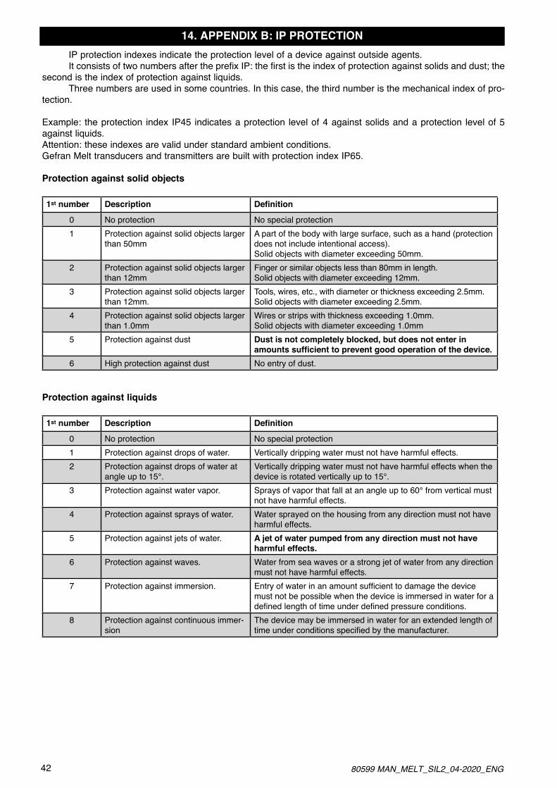
42 80599 MAN_MELT_SIL2_04-2020_ENG
14. APPENDIX B: IP PROTECTION IP protection indexes indicate the protection level of a device against outside agents. It consists of two numbers after the prefix IP: the first is the index of protection against solids and dust; the second is the index of protection against liquids. Three numbers are used in some countries. In this case, the third number is the mechanical index of pro-tection.
Example: the protection index IP45 indicates a protection level of 4 against solids and a protection level of 5 against liquids.Attention: these indexes are valid under standard ambient conditions.Gefran Melt transducers and transmitters are built with protection index IP65.
Protection against solid objects
1st number Description Definition
0 No protection No special protection1 Protection against solid objects larger
than 50mmA part of the body with large surface, such as a hand (protection does not include intentional access).Solid objects with diameter exceeding 50mm.
2 Protection against solid objects largerthan 12mm
Finger or similar objects less than 80mm in length.Solid objects with diameter exceeding 12mm.
3 Protection against solid objects largerthan 12mm.
Tools, wires, etc., with diameter or thickness exceeding 2.5mm.Solid objects with diameter exceeding 2.5mm.
4 Protection against solid objects largerthan 1.0mm
Wires or strips with thickness exceeding 1.0mm.Solid objects with diameter exceeding 1.0mm
5 Protection against dust Dust is not completely blocked, but does not enter in amounts sufficient to prevent good operation of the device.
6 High protection against dust No entry of dust.
Protection against liquids
1st number Description Definition
0 No protection No special protection1 Protection against drops of water. Vertically dripping water must not have harmful effects.2 Protection against drops of water at
angle up to 15°.Vertically dripping water must not have harmful effects when the device is rotated vertically up to 15°.
3 Protection against water vapor. Sprays of vapor that fall at an angle up to 60° from vertical must not have harmful effects.
4 Protection against sprays of water. Water sprayed on the housing from any direction must not have harmful effects.
5 Protection against jets of water. A jet of water pumped from any direction must not have harmful effects.
6 Protection against waves. Water from sea waves or a strong jet of water from any direction must not have harmful effects.
7 Protection against immersion. Entryofwaterinanamountsufficienttodamagethedevicemust not be possible when the device is immersed in water for a definedlengthoftimeunderdefinedpressureconditions.
8 Protection against continuous immer-sion
The device may be immersed in water for an extended length of timeunderconditionsspecifiedbythemanufacturer.
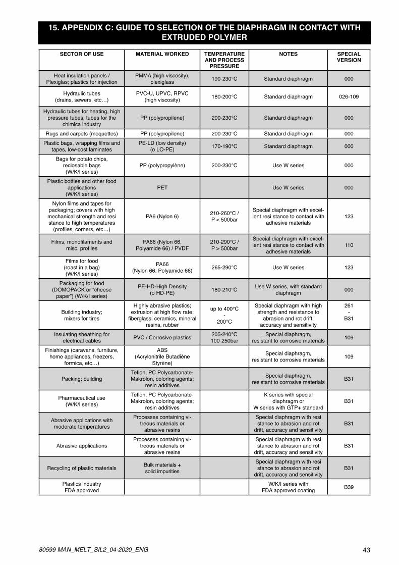
4380599 MAN_MELT_SIL2_04-2020_ENG
15. APPENDIX C: GUIDE TO SELECTION OF THE DIAPHRAGM IN CONTACT WITH EXTRUDED POLYMER
SECTOR OF USE MATERIAL WORKED TEMPERATUREAND PROCESS
PRESSURE
NOTES SPECIALVERSION
Heat insulation panels /Plexiglas; plastics for injection
PMMA (high viscosity),plexiglass 190-230°C Standard diaphragm 000
Hydraulic tubes(drains, sewers, etc…)
PVC-U, UPVC, RPVC (high viscosity) 180-200°C Standard diaphragm 026-109
Hydraulic tubes for heating, highpressure tubes, tubes for the
chimica industryPP (polypropilene) 200-230°C Standard diaphragm 000
Rugs and carpets (moquettes) PP (polypropilene) 200-230°C Standard diaphragm 000Plasticbags,wrappingfilmsand
tapes, low-cost laminatesPE-LD (low density)
(o LO-PE) 170-190°C Standard diaphragm 000
Bags for potato chips,reclosable bags(W/K/I series)
PP (polypropylène) 200-230°C Use W series 000
Plastic bottles and other foodapplications
(W/K/I series)PET Use W series 000
Nylonfilmsandtapesforpackaging; covers with highmechanical strength and resistance to high temperatures(profiles,corners,etc…)
PA6 (Nylon 6) 210-260°C / P < 500bar
Special diaphragm with excel-lent resi stance to contact with
adhesive materials123
Films,monofilamentsandmisc.profiles
PA66 (Nylon 66, Polyamide 66) / PVDF
210-290°C / P > 500bar
Special diaphragm with excel-lent resi stance to contact with
adhesive materials110
Films for food(roast in a bag)(W/K/I series)
PA66 (Nylon 66, Polyamide 66) 265-290°C Use W series 123
Packaging for food(DOMOPACK or “cheese
paper”) (W/K/I series)
PE-HD-High Density (o HD-PE) 180-210°C Use W series, with standard
diaphragm 000
Building industry;mixers for tires
Highly abrasive plastics;extrusionathighflowrate;fiberglass,ceramics,mineral
resins, rubber
up to 400°C-
200°C
Special diaphragm with high strength and resistance to
abrasion and rot drift,accuracy and sensitivity
261-
B31
Insulating sheathing forelectrical cables PVC / Corrosive plastics 205-240°C
100-250barSpecial diaphragm,
resistant to corrosive materials 109
Finishings (caravans, furniture,home appliances, freezers,
formica, etc…)
ABS (Acrylonitrile Butadiène
Styrène)
Special diaphragm,resistant to corrosive materials 109
Packing; buildingTeflon,PCPolycarbonate-Makrolon, coloring agents;
resin additives
Special diaphragm,resistant to corrosive materials B31
Pharmaceutical use(W/K/I series)
Teflon,PCPolycarbonate-Makrolon, coloring agents;
resin additives
K series with special diaphragm or
W series with GTP+ standardB31
Abrasive applications withmoderate temperatures
Processes containing vi-treous materials or
abrasive resins
Special diaphragm with resi stance to abrasion and rot
drift, accuracy and sensitivityB31
Abrasive applicationsProcesses containing vi-
treous materials or abrasive resins
Special diaphragm with resi stance to abrasion and rot
drift, accuracy and sensitivityB31
Recycling of plastic materials Bulk materials +solid impurities
Special diaphragm with resi stance to abrasion and rot
drift, accuracy and sensitivityB31
Plastics industryFDA approved
W/K/I series withFDA approved coating B39

44 80599 MAN_MELT_SIL2_04-2020_ENG
16. APPENDIX D: ACCURACY CLASS
Repeatability is defined as the ability to reproduce reads in the same direction and under the same conditions when the same pressure is applied consecutively.The maximum repeatability error of every Gefran sensor is 0.1% FS.
16.1. Calibration curve
16.2. Repeatability
Pressureread
Descentcurve
Rise curve
Repeatability
Hysteresis
Non-linearity
Referencepressure
Pressureread
Descentcurve
Rise curve
Repeatability
Hysteresis
Non-linearity
Referencepressure
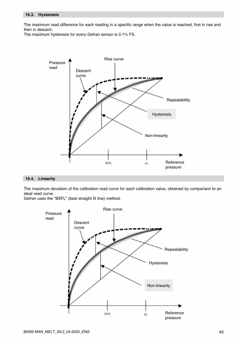
4580599 MAN_MELT_SIL2_04-2020_ENG
The maximum read difference for each reading in a specific range when the value is reached, first in rise and then in descent.The maximum hysteresis for every Gefran sensor is 0.1% FS.
16.3. Hysteresis
Pressureread
Descentcurve
Rise curve
Repeatability
Hysteresis
Non-linearity
Referencepressure
The maximum deviation of the calibration read curve for each calibration value, obtained by comparison to an ideal read curve. Gefran uses the “BSFL” (best straight fit line) method.
16.4. Linearity
Pressureread
Descentcurve
Rise curve
Repeatability
Hysteresis
Non-linearity
Referencepressure

46 80599 MAN_MELT_SIL2_04-2020_ENG
Dependent linearity error (End point)
Dependent linearity error is the deviation between the real characteristic of the transducer and the straight line passing through the two ends; expressed in % of FS.
Independent linearity error (BFSL)
Independent linearity error (BFSL) is the deviation between the real characteristic of the transducer and thestraight line of minimum squares.In practice, a straight line is formed that best approximates the real curve.
Pressure readCalibration curve
DependentLinearity
Reference pressure
BFS

4780599 MAN_MELT_SIL2_04-2020_ENG
Date DUT
(model/SN)
Maintenance Done Result Pass/Fail Operator Notes
In accordance with IEC/EN 62061 and IEC/EN 61508, transducers of the M, W, K SIL2 series also comply with EN 61326-3-1 “Electrical equipment for measurement, control, and laboratory use - immunity requirements for safety-related systems and for equipment intended to perform safety-related functions (functional safety) - Gen-eral industrial applications”.
17. APPENDIX E: REGISTRATION MAINTENANCE