prestressed construction technologies of the long- span
TRANSCRIPT
Proceedings of the International Association for Shell and Spatial Structures (IASS) Symposium 2009, Valencia Evolution and Trends in Design, Analysis and Construction of Shell and Spatial Structures
28 September – 2 October 2009, Universidad Politecnica de Valencia, Spain Alberto DOMINGO and Carlos LAZARO (eds.)
Prestressed Construction Technologies of the long-span Steel Structure of Olympic Stadiums
Jie QIN1, Ying- Xin QIAN2, Ran ZHANG3, Guo-Li LI4
1 Professor, Beijing Building Construction Research Institute No.34 Fu-xing Road, Beijing 100039, P. R. China
[email protected], www.bbcri.net
2 Professor, Beijing Building Construction Research Institute No.34 Fu-xing Road, Beijing 100039, P. R. China
[email protected], www.bbcri.net
3 Professor, Beijing Building Construction Research Institute No.34 Fu-xing Road, Beijing 100039, P. R. China
[email protected], www.bbcri.net
4 Professor, Beijing Building Construction Research Institute No.34 Fu-xing Road, Beijing 100039, P. R. China
[email protected], www.bbcri.net
Abstract Prestressed Steel Structure (PSS) is an outstanding structure type, which also appears a very modern style. This kind of structure is applied in some stadiums built for 2008 Olympic Games. How to control the cable prestress level is the key technology. In this paper, the prestressing technology of three main stadiums are accounted in detail. The projects’ brief introduction, prestressing technology, construction simulation and construction monitoring are included. Keywords: 2008 Olympic games; Olympic stadium; beam string structure; suspend-dome; prestressed steel structure; construction technology
1. National gymnasium
1.1. Summary The national gymnasium is one of the most important stadiums of 2008 Olympic Games besides the ‘bird's nest’ and ‘water cube’. The gymnasium is composed of two parts, namely the warm-up hall and competition hall. The competition hall’s plane size is
1963
Proceedings of the International Association for Shell and Spatial Structures (IASS) Symposium 2009, Valencia Evolution and Trends in Design, Analysis and Construction of Shell and Spatial Structures
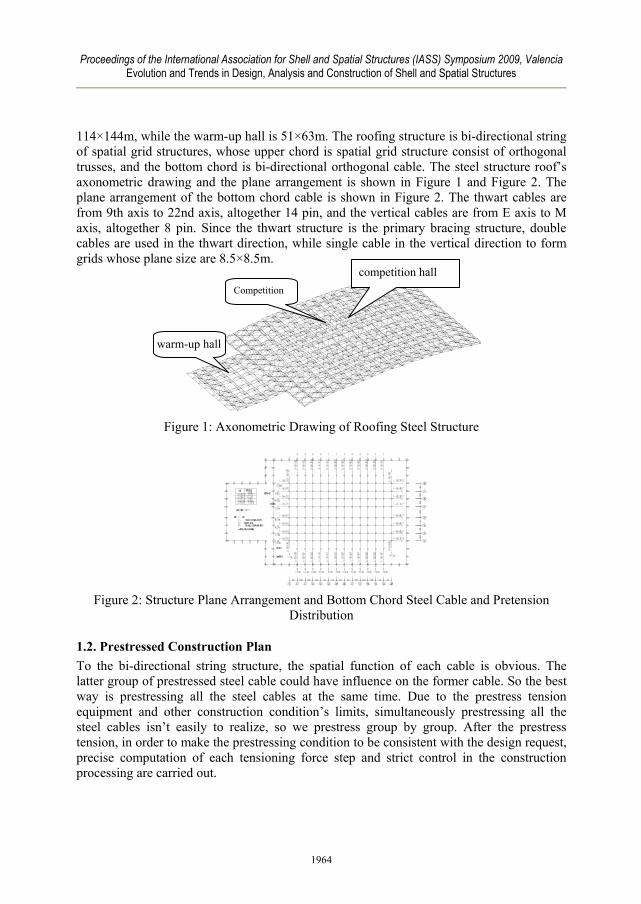
114×144m, while the warm-up hall is 51×63m. The roofing structure is bi-directional string of spatial grid structures, whose upper chord is spatial grid structure consist of orthogonal trusses, and the bottom chord is bi-directional orthogonal cable. The steel structure roof’s axonometric drawing and the plane arrangement is shown in Figure 1 and Figure 2. The plane arrangement of the bottom chord cable is shown in Figure 2. The thwart cables are from 9th axis to 22nd axis, altogether 14 pin, and the vertical cables are from E axis to M axis, altogether 8 pin. Since the thwart structure is the primary bracing structure, double cables are used in the thwart direction, while single cable in the vertical direction to form grids whose plane size are 8.5×8.5m.
Figure 1: Axonometric Drawing of Roofing Steel Structure
Figure 2: Structure Plane Arrangement and Bottom Chord Steel Cable and Pretension
Distribution
1.2. Prestressed Construction Plan To the bi-directional string structure, the spatial function of each cable is obvious. The latter group of prestressed steel cable could have influence on the former cable. So the best way is prestressing all the steel cables at the same time. Due to the prestress tension equipment and other construction condition’s limits, simultaneously prestressing all the steel cables isn’t easily to realize, so we prestress group by group. After the prestress tension, in order to make the prestressing condition to be consistent with the design request, precise computation of each tensioning force step and strict control in the construction processing are carried out.
warm-up hall
Competition
competition hall
1964
Proceedings of the International Association for Shell and Spatial Structures (IASS) Symposium 2009, Valencia Evolution and Trends in Design, Analysis and Construction of Shell and Spatial Structures
The national gymnasium makes the cable prestressed group by group. The prestressing infliction divides for 2 levels. The 1st level prestressed 80% of the tensioning force. The 2th level prestressed 100%, then it can meet the design requirements.
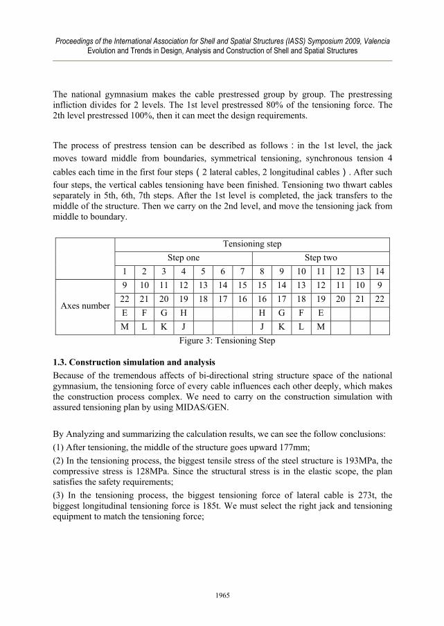
The process of prestress tension can be described as follows:in the 1st level, the jack moves toward middle from boundaries, symmetrical tensioning, synchronous tension 4 cables each time in the first four steps(2 lateral cables, 2 longitudinal cables). After such four steps, the vertical cables tensioning have been finished. Tensioning two thwart cables separately in 5th, 6th, 7th steps. After the 1st level is completed, the jack transfers to the middle of the structure. Then we carry on the 2nd level, and move the tensioning jack from middle to boundary.
Tensioning step Step one Step two
1 2 3 4 5 6 7 8 9 10 11 12 13 14 9 10 11 12 13 14 15 15 14 13 12 11 10 9
22 21 20 19 18 17 16 16 17 18 19 20 21 22 E F G H H G F E
Axes number
M L K J J K L M Figure 3: Tensioning Step
1.3. Construction simulation and analysis Because of the tremendous affects of bi-directional string structure space of the national gymnasium, the tensioning force of every cable influences each other deeply, which makes the construction process complex. We need to carry on the construction simulation with assured tensioning plan by using MIDAS/GEN. By Analyzing and summarizing the calculation results, we can see the follow conclusions: (1) After tensioning, the middle of the structure goes upward 177mm; (2) In the tensioning process, the biggest tensile stress of the steel structure is 193MPa, the compressive stress is 128MPa. Since the structural stress is in the elastic scope, the plan satisfies the safety requirements; (3) In the tensioning process, the biggest tensioning force of lateral cable is 273t, the biggest longitudinal tensioning force is 185t. We must select the right jack and tensioning equipment to match the tensioning force;
1965

Proceedings of the International Association for Shell and Spatial Structures (IASS) Symposium 2009, Valencia Evolution and Trends in Design, Analysis and Construction of Shell and Spatial Structures
1 2 3 4 5 6 7 8 9 10 11 12 13 140
25
50
75
100
125
150
175
200
225
250
275
300
??
?(
t)
? ? ? ?
14? ? ? ?
在 本 步 进 行 第 二 级 张 拉
在 本 步 进 行 第 一 级 张 拉
Figure 4: Roofing Steel Structure
Computation Model Figure 5: The Change Curve of 14th Axis
Tensioning By the Prestress Tension Level
Figure 6: Cable Tension Distributing
Drawing After Prestressing Figure 7 Displacement Drawing After
Prestressing (4) According to the tensioning process curve, plan 2 tensions the middle steel cable first. It has tremendous influence to the stress of steel cables in the following tensioning step. The change scope is large; the tensioning control difficulty also can increase correspondingly. Due to the above factors, we choose plan 1.
1.4. Construction monitor
1.4.1. Monitor Point Arrangement According to the tensioning construction request, construction monitor contains three parts: cable stress monitor, steel structure stress monitor, deformation monitor (longitudinal camber and bearing horizontal displacement). For the monitor of tensioning force of the cables ,we use tubing head pressure sensor connected with the oil pump, parts of the tensioning position uses the double-control measure, the oil pressure sensor and the pressure sensor together. Each tensioning position is provided a flowing tubing head pressure sensor. For the monitor of steel structure stress tensioning, we use vibrating wire strain gauge (Figure 10), the exact monitor points arrangement is shown in Figure 11; Uses
1966
Proceedings of the International Association for Shell and Spatial Structures (IASS) Symposium 2009, Valencia Evolution and Trends in Design, Analysis and Construction of Shell and Spatial Structures
the total station as the deformation monitor (Figure 12), the exact monitor points arrangement can see Figure 13 specifically. In pre-stressed construction processing, according to monitor results, whenever the structure deformation or the stress appears irregular, we should stop tensioning immediately. We must analysis the reason and inspect the structure, find out and solve the problems, and then we can continue the pre-stress tension.
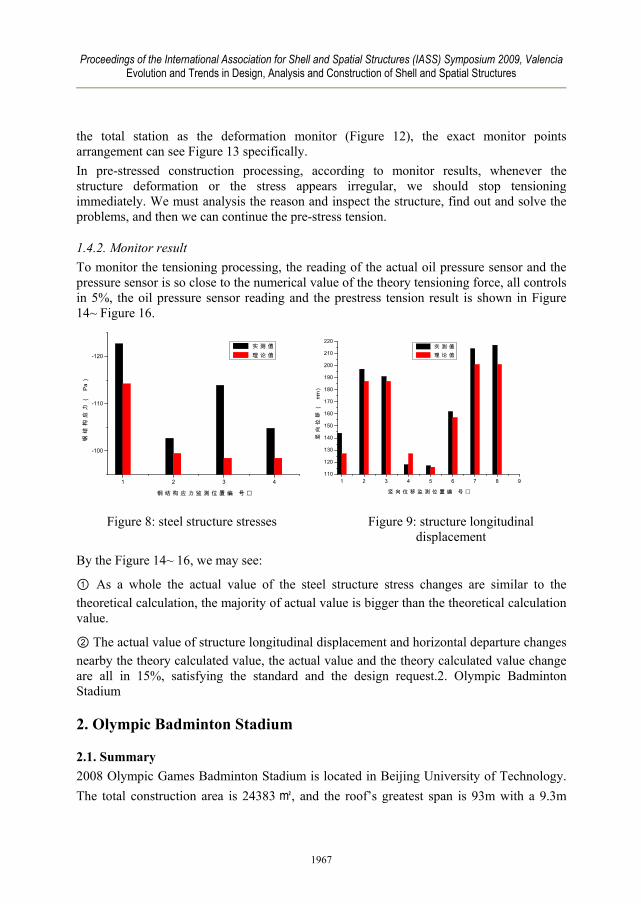
1.4.2. Monitor result To monitor the tensioning processing, the reading of the actual oil pressure sensor and the pressure sensor is so close to the numerical value of the theory tensioning force, all controls in 5%, the oil pressure sensor reading and the prestress tension result is shown in Figure 14~ Figure 16.
1 2 3 4
-100
-110
-120
钢结
构应
力(
Pa)
钢 结 构 应 力 监 测 位 置 编 号
实 测 值 理 论 值
1 2 3 4 5 6 7 8 9
110
120
130
140
150
160
170
180
190
200
210
220
竖向
位移
(mm
)
竖 向 位 移 监 测 位 置 编 号
实 测 值 理 论 值
Figure 8: steel structure stresses Figure 9: structure longitudinal displacement
By the Figure 14~ 16, we may see:
① As a whole the actual value of the steel structure stress changes are similar to the theoretical calculation, the majority of actual value is bigger than the theoretical calculation value.
② The actual value of structure longitudinal displacement and horizontal departure changes nearby the theory calculated value, the actual value and the theory calculated value change are all in 15%, satisfying the standard and the design request.2. Olympic Badminton Stadium
2. Olympic Badminton Stadium
2.1. Summary 2008 Olympic Games Badminton Stadium is located in Beijing University of Technology. The total construction area is 24383 ㎡, and the roof’s greatest span is 93m with a 9.3m
1967
Proceedings of the International Association for Shell and Spatial Structures (IASS) Symposium 2009, Valencia Evolution and Trends in Design, Analysis and Construction of Shell and Spatial Structures
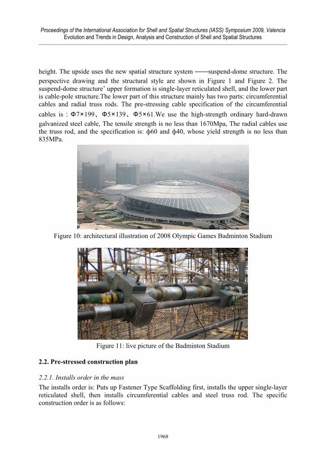
height. The upside uses the new spatial structure system ——suspend-dome structure. The perspective drawing and the structural style are shown in Figure 1 and Figure 2. The suspend-dome structure’ upper formation is single-layer reticulated shell, and the lower part is cable-pole structure.The lower part of this structure mainly has two parts: circumferential cables and radial truss rods. The pre-stressing cable specification of the circumferential cables is:Ф7×199、Ф5×139、Ф5×61.We use the high-strength ordinary hard-drawn galvanized steel cable, The tensile strength is no less than 1670Mpa, The radial cables use the truss rod, and the specification is: ф60 and ф40, whose yield strength is no less than 835MPa.
Figure 10: architectural illustration of 2008 Olympic Games Badminton Stadium
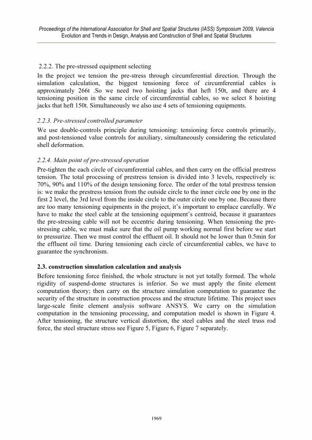
Figure 11: live picture of the Badminton Stadium
2.2. Pre-stressed construction plan
2.2.1. Installs order in the mass The installs order is: Puts up Fastener Type Scaffolding first, installs the upper single-layer reticulated shell, then installs circumferential cables and steel truss rod. The specific construction order is as follows:
1968
Proceedings of the International Association for Shell and Spatial Structures (IASS) Symposium 2009, Valencia Evolution and Trends in Design, Analysis and Construction of Shell and Spatial Structures
2.2.2. The pre-stressed equipment selecting In the project we tension the pre-stress through circumferential direction. Through the simulation calculation, the biggest tensioning force of circumferential cables is approximately 266t .So we need two hoisting jacks that heft 150t, and there are 4 tensioning position in the same circle of circumferential cables, so we select 8 hoisting jacks that heft 150t. Simultaneously we also use 4 sets of tensioning equipments.
2.2.3. Pre-stressed controlled parameter We use double-controls principle during tensioning: tensioning force controls primarily, and post-tensioned value controls for auxiliary, simultaneously considering the reticulated shell deformation.
2.2.4. Main point of pre-stressed operation Pre-tighten the each circle of circumferential cables, and then carry on the official prestress tension. The total processing of prestress tension is divided into 3 levels, respectively is: 70%, 90% and 110% of the design tensioning force. The order of the total prestress tension is: we make the prestress tension from the outside circle to the inner circle one by one in the first 2 level, the 3rd level from the inside circle to the outer circle one by one. Because there are too many tensioning equipments in the project, it’s important to emplace carefully. We have to make the steel cable at the tensioning equipment’s centroid, because it guarantees the pre-stressing cable will not be eccentric during tensioning. When tensioning the pre-stressing cable, we must make sure that the oil pump working normal first before we start to pressurize. Then we must control the effluent oil. It should not be lower than 0.5min for the effluent oil time. During tensioning each circle of circumferential cables, we have to guarantee the synchronism.
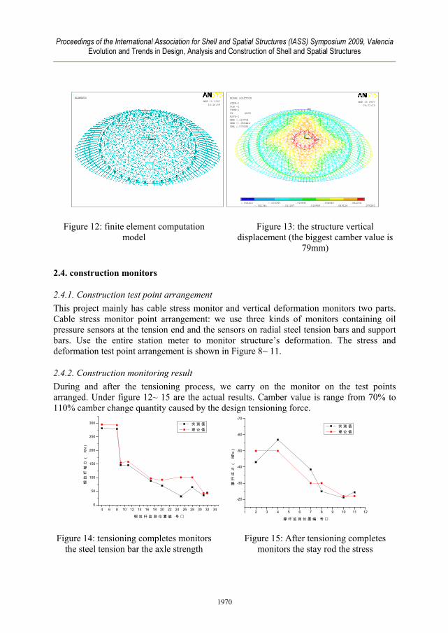
2.3. construction simulation calculation and analysis Before tensioning force finished, the whole structure is not yet totally formed. The whole rigidity of suspend-dome structures is inferior. So we must apply the finite element computation theory; then carry on the structure simulation computation to guarantee the security of the structure in construction process and the structure lifetime. This project uses large-scale finite element analysis software ANSYS. We carry on the simulation computation in the tensioning processing, and computation model is shown in Figure 4. After tensioning, the structure vertical distortion, the steel cables and the steel truss rod force, the steel structure stress see Figure 5, Figure 6, Figure 7 separately.
1969
Proceedings of the International Association for Shell and Spatial Structures (IASS) Symposium 2009, Valencia Evolution and Trends in Design, Analysis and Construction of Shell and Spatial Structures
1
XYZ
MAR 15 200716:16:59
ELEMENTS1
MN
MXX
YZ
-.056422
-.041344-.026265
-.011187.003891
.018969.034048
.049126.064204
.079283
MAR 15 200716:23:25
NODAL SOLUTION
STEP=1SUB =1TIME=1UZ (AVG)RSYS=1DMX =.110054SMN =-.056422SMX =.079283
Figure 12: finite element computation model
Figure 13: the structure vertical displacement (the biggest camber value is
79mm)
2.4. construction monitors
2.4.1. Construction test point arrangement This project mainly has cable stress monitor and vertical deformation monitors two parts. Cable stress monitor point arrangement: we use three kinds of monitors containing oil pressure sensors at the tension end and the sensors on radial steel tension bars and support bars. Use the entire station meter to monitor structure’s deformation. The stress and deformation test point arrangement is shown in Figure 8~ 11.
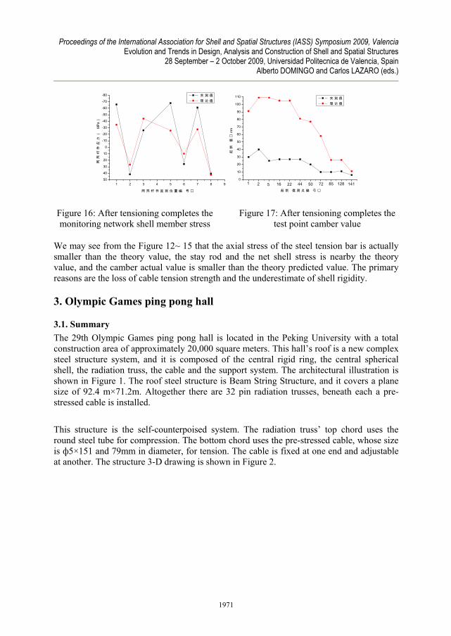
2.4.2. Construction monitoring result During and after the tensioning process, we carry on the monitor on the test points arranged. Under figure 12~ 15 are the actual results. Camber value is range from 70% to 110% camber change quantity caused by the design tensioning force.
4 6 8 10 12 14 16 18 20 22 24 26 28 30 32 340
50
100
150
200
250
300
钢拉
杆轴
力(
KN)
钢 拉 杆 监 测 位 置 编 号
实 测 值 理 论 值
1 2 3 4 5 6 7 8 9 10 11 12
-20
-30
-40
-50
-60
-70
撑杆
应力
(MP
a)
撑 杆 监 测 位 置 编 号
实 测 值 理 论 值
Figure 14: tensioning completes monitors the steel tension bar the axle strength
Figure 15: After tensioning completes monitors the stay rod the stress
1970
Proceedings of the International Association for Shell and Spatial Structures (IASS) Symposium 2009, Valencia Evolution and Trends in Design, Analysis and Construction of Shell and Spatial Structures
28 September – 2 October 2009, Universidad Politecnica de Valencia, Spain Alberto DOMINGO and Carlos LAZARO (eds.)
1 2 3 4 5 6 7 8 950
40
30
20
10
0
-10
-20
-30
-40
-50
-60
-70
-80网
壳杆
件应
力(
MPa)
网 壳 杆 件 监 测 位 置 编 号
实 测 值 理 论 值
0
10
20
30
40
50
60
70
80
90
100
110
141128857250442216521
起拱
值
mm
起 拱 值 测 点 编 号
实 测 值 理 论 值
Figure 16: After tensioning completes the monitoring network shell member stress
Figure 17: After tensioning completes the test point camber value
We may see from the Figure 12~ 15 that the axial stress of the steel tension bar is actually smaller than the theory value, the stay rod and the net shell stress is nearby the theory value, and the camber actual value is smaller than the theory predicted value. The primary reasons are the loss of cable tension strength and the underestimate of shell rigidity.
3. Olympic Games ping pong hall
3.1. Summary The 29th Olympic Games ping pong hall is located in the Peking University with a total construction area of approximately 20,000 square meters. This hall’s roof is a new complex steel structure system, and it is composed of the central rigid ring, the central spherical shell, the radiation truss, the cable and the support system. The architectural illustration is shown in Figure 1. The roof steel structure is Beam String Structure, and it covers a plane size of 92.4 m×71.2m. Altogether there are 32 pin radiation trusses, beneath each a pre-stressed cable is installed. This structure is the self-counterpoised system. The radiation truss’ top chord uses the round steel tube for compression. The bottom chord uses the pre-stressed cable, whose size is ф5×151 and 79mm in diameter, for tension. The cable is fixed at one end and adjustable at another. The structure 3-D drawing is shown in Figure 2.
1971
Proceedings of the International Association for Shell and Spatial Structures (IASS) Symposium 2009, Valencia Evolution and Trends in Design, Analysis and Construction of Shell and Spatial Structures
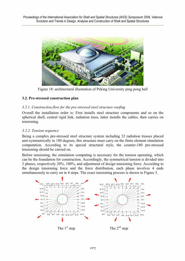
Figure 18: architectural illustration of Peking University ping pong hall
3.2. Pre-stressed construction plan
3.2.1. Construction flow for the pre-stressed steel structure roofing Overall the installation order is: First installs steel structure components and so on the spherical shell, central rigid link, radiation truss, latter installs the cables, then carries on tensioning.
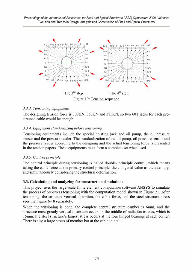
3.2.2. Tension sequence Being a complex pre-stressed steel structure system including 32 radiation trusses placed anti-symmetrically in 180 degrees, this structure must carry on the finite element simulation computation. According to its special structural style, the counter-180 pre-stressed tensioning should be carried on. Before tensioning, the simulation computing is necessary for the tension operating, which can be the foundation for construction. Accordingly, the symmetrical tension is divided into 3 phases, respectively 20%, 100%, and adjustment of design tensioning force. According to the design tensioning force and the force distribution, each phase involves 4 ends simultaneously to carry on in 4 steps. The exact tensioning process is shown in Figure 3.
The 1st step The 2nd step
1972
Proceedings of the International Association for Shell and Spatial Structures (IASS) Symposium 2009, Valencia Evolution and Trends in Design, Analysis and Construction of Shell and Spatial Structures
The 3rd step The 4th step
Figure 19: Tension sequence
3.3.3. Tensioning equipments The designing tension force is 308KN, 350KN and 385KN, so two 60T jacks for each pre-stressed cable would be enough.
3.3.4. Equipment standardizing before tensioning Tensioning equipments include the special hoisting jack and oil pump, the oil pressure sensor and the pressure reader. The standardization of the oil pump, oil pressure sensor and the pressure reader according to the designing and the actual tensioning force is presented in the tension papers. These equipments must form a complete set when used.
3.3.5. Control principle The control principle during tensioning is called double- principle control, which means taking the cable force as the primary control principle, the elongated value as the auxiliary, and simultaneously considering the structural deformation.
3.3. Calculating and analyzing for construction simulations This project uses the large-scale finite element computation software ANSYS to simulate the process of pre-stress tensioning with the computation model shown in Figure 21. After tensioning, the structure vertical distortion, the cable force, and the steel structure stress sees the Figure 6~ 8 separately. When the tensioning is done, the complete central structure camber is 6mm, and the structure most greatly vertical distortion occurs in the middle of radiation trusses, which is 15mm.The steel structure’s largest stress occurs at the four hinged bearings at each corner. There is also a large stress of member bar at the cable joints.
1973
Proceedings of the International Association for Shell and Spatial Structures (IASS) Symposium 2009, Valencia Evolution and Trends in Design, Analysis and Construction of Shell and Spatial Structures
X
Y
Z
UROTACEL
Figure 20: Model for FEM Figure 21: Structural vertical distortion
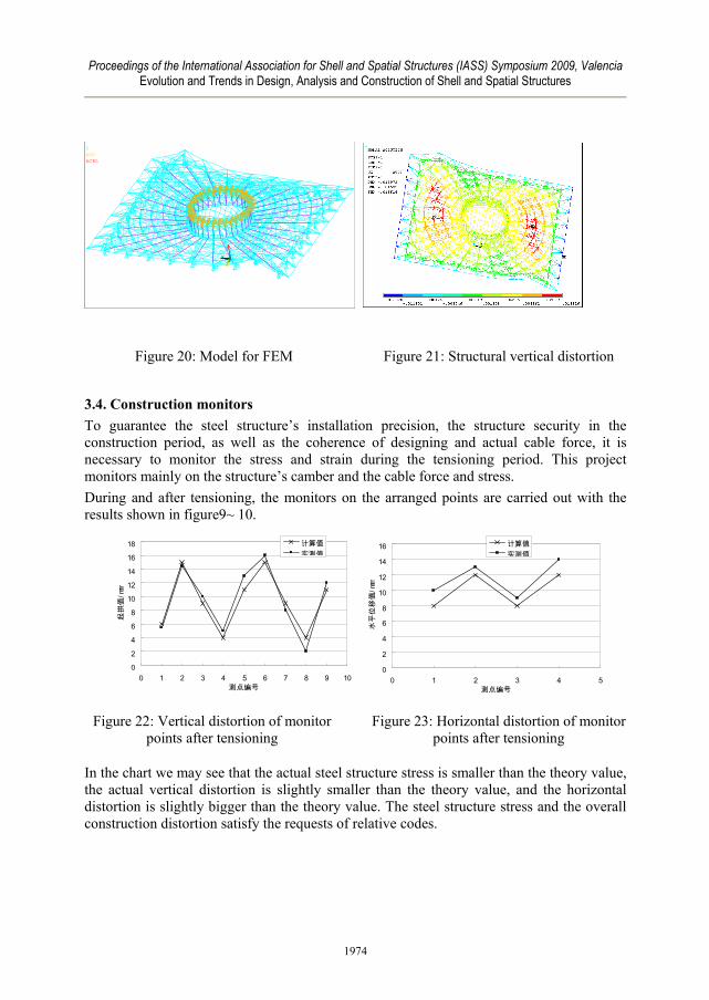
3.4. Construction monitors To guarantee the steel structure’s installation precision, the structure security in the construction period, as well as the coherence of designing and actual cable force, it is necessary to monitor the stress and strain during the tensioning period. This project monitors mainly on the structure’s camber and the cable force and stress. During and after tensioning, the monitors on the arranged points are carried out with the results shown in figure9~ 10.
0
2
4
6
8
10
12
14
16
18
0 1 2 3 4 5 6 7 8 9 10测点编号
起拱
值/m
m
计算值实测值
0
2
4
6
8
10
12
14
16
0 1 2 3 4 5测点编号
水平
位移
值/m
m
计算值实测值
Figure 22: Vertical distortion of monitor points after tensioning
Figure 23: Horizontal distortion of monitor points after tensioning
In the chart we may see that the actual steel structure stress is smaller than the theory value, the actual vertical distortion is slightly smaller than the theory value, and the horizontal distortion is slightly bigger than the theory value. The steel structure stress and the overall construction distortion satisfy the requests of relative codes.
1974