primecluster™ 4 - fujitsumanuals.ts.fujitsu.com/file/4252/primecluster-inst-en.pdf · 12...
TRANSCRIPT

Edition June 2009
PRIMECLUSTER™ 4.2A20Installation Guide (Linux®)

This manual is printed on paper treated with chlorine-free bleach.
Comments… Suggestions… Corrections…The User Documentation Department would like toknow your opinion of this manual. Your feedback helpsus optimize our documentation to suit your individual needs.
Feel free to send us your comments by e-mail to [email protected].
Certified documentation according to DIN EN ISO 9001:2000To ensure a consistently high quality standard anduser-friendliness, this documentation was created tomeet the regulations of a quality management system which complies with the requirements of the standardDIN EN ISO 9001:2000.
cognitas. Gesellschaft für Technik-Dokumentation mbHwww.cognitas.de
Copyright and TrademarksCopyright © 2002 through 2009 Fujitsu LIMITED.
All rights reserved.Delivery subject to availability; right of technical modifications reserved.
All hardware and software names used are trademarks of their respective manufacturers.

U42123-J-Z100-7-76
Contents
1 Preface . . . . . . . . . . . . . . . . . . . . . . . . . . . . . . 9
1.1 Contents of this manual . . . . . . . . . . . . . . . . . . . . . 9
1.2 PRIMECLUSTER documentation . . . . . . . . . . . . . . . 11
1.3 Conventions . . . . . . . . . . . . . . . . . . . . . . . . . . 131.3.1 Notation . . . . . . . . . . . . . . . . . . . . . . . . . . . . . 131.3.1.1 Prompts . . . . . . . . . . . . . . . . . . . . . . . . . . . 131.3.1.2 Manual page section numbers . . . . . . . . . . . . . . . . 131.3.1.3 The keyboard . . . . . . . . . . . . . . . . . . . . . . . . . 131.3.1.4 Typefaces . . . . . . . . . . . . . . . . . . . . . . . . . . 141.3.1.5 Example 1 . . . . . . . . . . . . . . . . . . . . . . . . . . 141.3.1.6 Example 2 . . . . . . . . . . . . . . . . . . . . . . . . . . 141.3.2 Command syntax . . . . . . . . . . . . . . . . . . . . . . . . 15
1.4 Notation symbols . . . . . . . . . . . . . . . . . . . . . . . . 15
2 Site planning . . . . . . . . . . . . . . . . . . . . . . . . . . 17
2.1 Planning your site . . . . . . . . . . . . . . . . . . . . . . . 172.1.1 Cluster configuration information . . . . . . . . . . . . . . . . 192.1.1.1 Assigning the TCP/IP addresses . . . . . . . . . . . . . . . 202.1.1.2 Assigning the CF cluster name . . . . . . . . . . . . . . . 212.1.1.3 Identifying the interfaces to be used on each node . . . . . 212.1.1.4 Setting up CF over IP . . . . . . . . . . . . . . . . . . . . 212.1.1.5 TCP/IP addresses for CIP . . . . . . . . . . . . . . . . . . 222.1.1.6 TCP/IP addresses for the system administration network . . 222.1.1.7 TCP/IP addresses for the cluster interconnect . . . . . . . . 22
2.2 Disk space requirements . . . . . . . . . . . . . . . . . . . 23
2.3 Pre-installation configuration steps . . . . . . . . . . . . . 26
2.4 Time synchronization . . . . . . . . . . . . . . . . . . . . . 29
2.5 Browser environments . . . . . . . . . . . . . . . . . . . . . 29
2.6 Planning needed for SIS and blade servers . . . . . . . . . 30
2.7 Configuring user groups . . . . . . . . . . . . . . . . . . . . 30

U42123-J-Z100-7-76
Contents
3 Installation with CLI . . . . . . . . . . . . . . . . . . . . . . . 33
3.1 Product set installation . . . . . . . . . . . . . . . . . . . . . 33
3.2 Installing a single product . . . . . . . . . . . . . . . . . . . 35
3.3 Installation on an external management server . . . . . . . . 36
4 External management servers . . . . . . . . . . . . . . . . . 37
4.1 Benefits . . . . . . . . . . . . . . . . . . . . . . . . . . . . . 37
4.2 Hardware and software requirements . . . . . . . . . . . . . 38
4.3 Package list . . . . . . . . . . . . . . . . . . . . . . . . . . . 38
4.4 Installation procedure . . . . . . . . . . . . . . . . . . . . . . 40
4.5 Uninstall procedure . . . . . . . . . . . . . . . . . . . . . . . 41
5 SIS Satellite node installation . . . . . . . . . . . . . . . . . 43
5.1 Overview . . . . . . . . . . . . . . . . . . . . . . . . . . . . . 43
5.2 Installing on Microsoft Windows . . . . . . . . . . . . . . . . 43
6 Web-Based Admin View configuration . . . . . . . . . . . . . 45
6.1 Web-Based Admin View Concepts . . . . . . . . . . . . . . . 45
6.2 Updating /etc/hosts . . . . . . . . . . . . . . . . . . . . . . . 46
6.3 Using wvconf . . . . . . . . . . . . . . . . . . . . . . . . . . 46
6.4 wvconf example . . . . . . . . . . . . . . . . . . . . . . . . . 48
6.5 Checking the configuration . . . . . . . . . . . . . . . . . . . 516.5.1 Checking the configuration using the CLI . . . . . . . . . . . . . 516.5.2 Checking the configuration using the GUI . . . . . . . . . . . . 52
6.6 Save and restore . . . . . . . . . . . . . . . . . . . . . . . . . 586.6.1 Saving the configuration . . . . . . . . . . . . . . . . . . . . . 586.6.2 Restoring the configuration . . . . . . . . . . . . . . . . . . . . 58

U42123-J-Z100-7-76
Contents
7 Installation example . . . . . . . . . . . . . . . . . . . . . . 61
7.1 Network setup . . . . . . . . . . . . . . . . . . . . . . . . . 637.1.1 Verifying the cluster interconnect networks . . . . . . . . . . . 64
7.2 Java environment . . . . . . . . . . . . . . . . . . . . . . . . 64
7.3 Installing the cluster nodes . . . . . . . . . . . . . . . . . . 64
7.4 PRIMECLUSTER software configuration . . . . . . . . . . . 657.4.1 Web-Based Admin View example . . . . . . . . . . . . . . . . 667.4.2 Signed applets . . . . . . . . . . . . . . . . . . . . . . . . . . 697.4.3 CF, CIP, and SF example . . . . . . . . . . . . . . . . . . . . 697.4.4 SIS example . . . . . . . . . . . . . . . . . . . . . . . . . . . 967.4.5 PCS example . . . . . . . . . . . . . . . . . . . . . . . . . . 1177.4.5.1 Starting PCS . . . . . . . . . . . . . . . . . . . . . . . . . 1187.4.5.2 Selecting a node for the PCS session . . . . . . . . . . . . 1197.4.5.3 Creating a new configuration . . . . . . . . . . . . . . . . . 1207.4.5.4 Selecting nodes . . . . . . . . . . . . . . . . . . . . . . . 1217.4.5.5 Viewing the configuration tree . . . . . . . . . . . . . . . . 1237.4.5.6 Choosing the application template . . . . . . . . . . . . . . 1237.4.5.7 Changing the application name . . . . . . . . . . . . . . . 1257.4.5.8 Viewing template information . . . . . . . . . . . . . . . . 1267.4.5.9 Selecting nodes for the application . . . . . . . . . . . . . . 1277.4.5.10 Setting application parameters . . . . . . . . . . . . . . . . 1287.4.5.11 Configuring a subapplication . . . . . . . . . . . . . . . . . 1297.4.5.12 Checking application consistency . . . . . . . . . . . . . . 1337.4.5.13 Saving the configuration . . . . . . . . . . . . . . . . . . . 1347.4.5.14 Activating the configuration . . . . . . . . . . . . . . . . . 134
8 PRIMECLUSTER upgrade . . . . . . . . . . . . . . . . . . . 137
8.1 Overview . . . . . . . . . . . . . . . . . . . . . . . . . . . . 138
8.2 Cautions . . . . . . . . . . . . . . . . . . . . . . . . . . . . 138
8.3 Preparation . . . . . . . . . . . . . . . . . . . . . . . . . . . 1398.3.1 Verify cluster upgrade capability . . . . . . . . . . . . . . . . . 1398.3.2 Backup . . . . . . . . . . . . . . . . . . . . . . . . . . . . . . 1408.3.3 Upgrade preparation . . . . . . . . . . . . . . . . . . . . . . . 1428.3.3.1 Install patches . . . . . . . . . . . . . . . . . . . . . . . . 1428.3.3.2 Decide the node upgrade order . . . . . . . . . . . . . . . 1428.3.3.3 RMS preparation . . . . . . . . . . . . . . . . . . . . . . . 1438.3.3.4 Save Web-Based Admin View configuration file . . . . . . . 144

U42123-J-Z100-7-76
Contents
8.4 Upgrading SIS satellite nodes . . . . . . . . . . . . . . . . 145
8.5 Performing the rolling upgrade . . . . . . . . . . . . . . . . 1458.5.1 Switching RMS applications . . . . . . . . . . . . . . . . . . 1468.5.2 Shutdown node A . . . . . . . . . . . . . . . . . . . . . . . . 1488.5.3 Upgrading the software on node A . . . . . . . . . . . . . . . 1498.5.3.1 Manually removing PRIMECLUSTER packages . . . . . . 1498.5.3.2 Removing the remaining old PRIMECLUSTER packages . 1508.5.3.3 Removing persisting PRIMECLUSTER kernel drivers . . . 1518.5.3.4 Verify supported OS level . . . . . . . . . . . . . . . . . . 1518.5.3.5 Installing new PRIMECLUSTER packages . . . . . . . . . 1528.5.4 Joining node A back to the cluster . . . . . . . . . . . . . . . 1528.5.5 Upgrading the next node . . . . . . . . . . . . . . . . . . . . 154
8.6 Post-installation . . . . . . . . . . . . . . . . . . . . . . . . 1548.6.1 Restoring Web-Based Admin View configuration . . . . . . . . 1548.6.2 Configuring the new RMS version . . . . . . . . . . . . . . . 155
8.7 Conclusion . . . . . . . . . . . . . . . . . . . . . . . . . . . 162
9 Manual pages . . . . . . . . . . . . . . . . . . . . . . . . . 163
9.1 CCBR . . . . . . . . . . . . . . . . . . . . . . . . . . . . . . 163
9.2 CF . . . . . . . . . . . . . . . . . . . . . . . . . . . . . . . . 163
9.3 CIP . . . . . . . . . . . . . . . . . . . . . . . . . . . . . . . 164
9.4 Monitoring Agent . . . . . . . . . . . . . . . . . . . . . . . 164
9.5 PAS . . . . . . . . . . . . . . . . . . . . . . . . . . . . . . . 164
9.6 PCS . . . . . . . . . . . . . . . . . . . . . . . . . . . . . . . 165
9.7 Resource Database . . . . . . . . . . . . . . . . . . . . . . 166
9.8 RMS . . . . . . . . . . . . . . . . . . . . . . . . . . . . . . . 167
9.9 RMS Wizards . . . . . . . . . . . . . . . . . . . . . . . . . . 168
9.10 SF . . . . . . . . . . . . . . . . . . . . . . . . . . . . . . . . 168
9.11 SIS . . . . . . . . . . . . . . . . . . . . . . . . . . . . . . . 169
9.12 Web-Based Admin View . . . . . . . . . . . . . . . . . . . . 169
10 Appendix—Important Web-Based Admin View settings . . 171

U42123-J-Z100-7-76
Contents
11 Appendix—Private network addresses . . . . . . . . . . . . 175
12 Appendix—Cluster planning worksheet . . . . . . . . . . . 177
13 Appendix—Product sets and packages . . . . . . . . . . . 179
13.1 Location of packages on CDs . . . . . . . . . . . . . . . . . 184
13.2 Installation order . . . . . . . . . . . . . . . . . . . . . . . . 187
14 Appendix—System parameters . . . . . . . . . . . . . . . . 189
14.1 Kernel parameters for Resource Database . . . . . . . . . . 189
14.2 System parameters for RMS configurations . . . . . . . . . 191
15 Appendix—PRIMECLUSTER ports . . . . . . . . . . . . . . 193
16 Appendix—Troubleshooting . . . . . . . . . . . . . . . . . . 197
16.1 cluster_install log files . . . . . . . . . . . . . . . . . . . . . 197
16.2 cluster_install error messages . . . . . . . . . . . . . . . . 197
16.3 cluster_uninstall error messages . . . . . . . . . . . . . . . 201
16.4 CF dependency issues . . . . . . . . . . . . . . . . . . . . . 203

U42123-J-Z100-7-76
Contents
Glossary . . . . . . . . . . . . . . . . . . . . . . . . . . . . . . . . . 205
Abbreviations . . . . . . . . . . . . . . . . . . . . . . . . . . . . . . . 223
Figures . . . . . . . . . . . . . . . . . . . . . . . . . . . . . . . . . . 227
Tables . . . . . . . . . . . . . . . . . . . . . . . . . . . . . . . . . . . 233
Index . . . . . . . . . . . . . . . . . . . . . . . . . . . . . . . . . . . 235

U42123-J-Z100-7-76 9
1 PrefaceThis guide provides instructions for installing the PRIMECLUSTER suite of products. The primary audience for this guide is the system administrator. This guide assumes that the reader is familiar with the PRIMECLUSTER Concepts Guide and assumes that the hardware has been installed according to the appropriate hardware installation manuals.
This version of PRIMECLUSTER includes the following components:
● Cluster Foundation (CF) 4.2A20
● Reliant Monitor Services (RMS) 4.2A20
● Wizard Tools (WT) 4.2A20
● PRIMECLUSTER Configuration Services (PCS) 4.2A20
● Scalable Internet Services (SIS) 4.2A20
● Parallel Application Services (PAS) 4.2A20
● Global Disk Services (GDS) 4.2A20
● Global File Services (GFS) 4.2A20
● Global Link Services (GLS) 4.2A20
In this manual, Linux stands for the supported Linux distributions as follows:
● Novell SUSE
● Red Hat
I Refer to the release note for versions of the supported distributions of Linux.
1.1 Contents of this manual
This manual is organized as follows:
● The chapter “Site planning” provides hardware and software information for planning your site.
● The chapter “Installation with CLI” provides information on installing the PRIMECLUSTER products by means of the command line interface (CLI) installer.

10 U42123-J-Z100-7-76
Contents of this manual Preface
● The chapter “External management servers” describes how to install Web-Based Admin View software and related GUIs on the management server when the server is a node outside of the cluster.
● The chapter “SIS Satellite node installation” provides information on installing SIS satellite nodes.
● The chapter “Web-Based Admin View configuration” details the wvconf command to configure the PRIMECLUSTER GUI.
● The chapter “Installation example” provides a step-by-step example of installing, configuring and starting a sample two-node cluster configuration.
● The chapter “PRIMECLUSTER upgrade” describes the rolling upgrade process.
● The chapter “Manual pages” contains a listing of PRIMECLUSTER manual pages.
● The chapter “Appendix—Important Web-Based Admin View settings” describes useful Web-Based Admin settings.
● The chapter “Appendix—Private network addresses” defines three address ranges that are set aside for private subnets.
● The chapter “Appendix—Cluster planning worksheet” provides a blank cluster planning worksheet.
● The chapter “Appendix—Product sets and packages” lists the configuration for each product set and single product, and the packages on the PRIMECLUSTER CDs.
● The chapter “Appendix—System parameters” discusses setting system parameters for both CF and RMS configurations.
● The chapter “Appendix—PRIMECLUSTER ports” lists the ports used by PRIMECLUSTER.
● The chapter “Appendix—Troubleshooting” provides cluster_install trouble-shooting details and error messages.

U42123-J-Z100-7-76 11
Preface PRIMECLUSTER documentation
1.2 PRIMECLUSTER documentation
The documents listed below provide details about PRIMECLUSTER products. Books can be ordered via the Internet shop http://manualshop.ts.fujitsu.com.
● Release notices for all products—These documentation files are included as HTML files on the PRIMECLUSTER CD. Release notices provide late-breaking information about installation, configuration, and operations for PRIMECLUSTER. Read this information first.
● Concepts Guide (Solaris, Linux)—Provides conceptual details on the PRIMECLUSTER family of products.
● Installation Guide (Solaris)—Provides instructions for installing and upgrading PRIMECLUSTER products on Solaris.
● Installation Guide (Linux)—Provides instructions for installing and upgrading PRIMECLUSTER products on Linux.
● Web-Based Admin View (Solaris, Linux) Operation Guide—Provides information on using the Web-Based Admin View management GUI.
● Cluster Foundation (CF) (Solaris) Configuration and Administration Guide—Provides instructions for configuring and administering the PRIMECLUSTER Cluster Foundation on Solaris.
● Cluster Foundation (CF) (Linux) Configuration and Administration Guide—Provides instructions for configuring and administering the PRIMECLUSTER Cluster Foundation on Linux.
● Reliant Monitor Services (RMS) with Wizard Tools (Solaris, Linux) Configuration and Administration Guide—Provides instructions for configuring and adminis-tering PRIMECLUSTER Reliant Monitor Services using the Wizard Tools interface.
● Reliant Monitor Services (RMS) with PCS (Solaris, Linux) Configuration and Administration Guide—Provides instructions for configuring and adminis-tering PRIMECLUSTER Reliant Monitor Services using the PCS (PRIME-CLUSTER Configuration Services) interface.
● Reliant Monitor Services (RMS) (Solaris, Linux) Reference Guide—Describes diagnostic procedures to solve RMS configuration problems, including how to view and interpret RMS log files. Provides a list of all RMS error messages with a probable cause and suggested action for each condition.

12 U42123-J-Z100-7-76
PRIMECLUSTER documentation Preface
● Scalable Internet Services (SIS) (Solaris, Linux) Configuration and Administration Guide—Provides information on configuring and administering Scalable Internet Services (SIS).
● Global Disk Services (Solaris, Linux) Configuration and Administration Guide—Provides information on configuring and administering Global Disk Services (GDS).
● Global File Services (Solaris, Linux) Configuration and Administration Guide—Provides information on configuring and administering Global File Services (GFS).
● Global Link Services (Solaris, Linux) Configuration and Administration Guide: Redundant Line Control Function—Provides information on configuring and administering the redundant line control function for Global Link Services (GLS).
● Global Link Services (Solaris, Linux) Configuration and Administration Guide: Multipath Function—Provides information on configuring and administering the multipath function for Global Link Services (GLS).
● Data Management Tools (Solaris) Configuration and Administration Guide—Provides reference information on the Volume Manager (RCVM) and File Share (RCFS) products. (Not available in all markets.)
● SNMP Reference Manual (Solaris, Linux)—Provides reference information on the Simple Network Management Protocol (SNMP) product.

U42123-J-Z100-7-76 13
Preface Conventions
1.3 Conventions
In order to standardize the presentation of material, this manual uses a number of notational, typographical, and syntactical conventions.
1.3.1 Notation
This manual uses the following notational conventions.
1.3.1.1 Prompts
Command line examples that require system administrator (or root) privileges to execute are preceded by the system administrator prompt, the hash sign (#). Entries that do not require system administrator rights are preceded by a dollar sign ($).
In some examples, the notation node# indicates a root prompt on the specified node. For example, a command preceded by shasta2# would mean that the command was run as user root on the node named shasta2.
1.3.1.2 Manual page section numbers
References to operating system commands may sometimes be followed by their manual page section numbers in parentheses, e.g., cp(1).
1.3.1.3 The keyboard
Keystrokes that represent nonprintable characters are displayed as key icons such as [Enter] or [F1]. For example, [Enter] means press the key labeled Enter; [Ctrl-b] means hold down the key labeled Ctrl or Control and then press the [B] key.

14 U42123-J-Z100-7-76
Conventions Preface
1.3.1.4 Typefaces
The following typefaces highlight specific elements in this manual.
Typeface conventions are shown in the following examples.
1.3.1.5 Example 1
As an example, several entries from an /etc/passwd file are shown below:
sysadm:x:0:0:System Admin.:/usr/admin:/usr/sbin/sysadmsetup:x:0:0:System Setup:/usr/admin:/usr/sbin/setupdaemon:x:1:1:0000-Admin(0000):/:
1.3.1.6 Example 2
To use the cat command to display the contents of a file, enter the following command line:
$ cat file
Typeface Usage
Constant Width
Computer output and program listings; commands, file names, manual page names and other literal programming elements in the main body of text.
Italic Variables in a command line that you must replace with an actual value. May be enclosed in angle brackets to emphasize the difference from adjacent text; for example, <nodename>RMS; unless directed otherwise, you should not enter the angle brackets.
The name of an item in a character-based or graphical user interface. This may refer to a menu item, a radio button, a checkbox, a text input box, a panel, or a window title.
Bold Items in a command line that you must type exactly as shown.

U42123-J-Z100-7-76 15
Preface Notation symbols
1.3.2 Command syntax
The command syntax observes the following conventions.
1.4 Notation symbols
Material of particular interest is preceded by the following symbols in this manual:
I Contains important information about the subject at hand.
V Caution
Indicates a situation that can cause harm to data.
Symbol Name Meaning
[ ] Brackets Enclose an optional item.
{ } Braces Enclose two or more items of which only one is used. The items are separated from each other by a vertical bar (|).
| Vertical bar When enclosed in braces, it separates items of which only one is used. When not enclosed in braces, it is a literal element indicating that the output of one program is piped to the input of another.
( ) Parentheses Enclose items that must be grouped together when repeated.
... Ellipsis Signifies an item that may be repeated. If a group of items can be repeated, the group is enclosed in parentheses.


U42123-J-Z100-7-76 17
2 Site planningThis chapter provides information for planning your site. Both hardware and software planning are discussed.
This chapter discusses the following:
● The section “Planning your site” describes a generic hardware configuration.
● The section “Disk space requirements” lists the space requirements for PRIMECLUSTER products and packages.
● The section “Pre-installation configuration steps” provides a list of additional steps to perform before starting the installation of PRIMECLUSTER.
● The section “Time synchronization” recommends the use of time synchroni-zation to analyze problems in a clustered environment.
● The section “Browser environments” discusses the environments supported by the Web-Based Admin View browser, and what settings must be done for the browser.
● The section “Planning needed for SIS and blade servers” describes setting up PRIMECLUSTER Scalable Internet Services (SIS) and SIS satellite nodes on a BLADE server environment.
● The section “Configuring user groups” discusses configuring user groups with the Web-Based Admin View browser.
2.1 Planning your site
The configuration shown in figure 1 is a typical example of a two-node cluster. The major components of interest are as follows:
● Cluster interconnects—These are Ethernet networks or IP interfaces dedicated to Cluster Foundation's use. Refer to the PRIMECLUSTER Cluster Foundation (CF) (Linux®) Configuration and Administration Guide for details.

18 U42123-J-Z100-7-76
Planning your site Site planning
● System administration network—This is the network that is used for admin-istrative purposes. It is often a private network for security reasons. However, a public network may also be used. Refer to the PRIMECLUSTER Cluster Foundation (CF) (Linux®) Configuration and Administration manual for details.
● Cluster nodes—These are the nodes bound together in a CF cluster and running the PRIMECLUSTER software.
In addition to the cluster interconnects and system administration network, each cluster node should also have an interface on a public network. For the sake of simplicity, the public network for each node is not shown in figure 1.
Figure 1: PRIMECLUSTER hardware configuration without a console
In figure 1, the power switch is a Network Power Switch (NPS) or Remote Power Switch (RPS). The power plugs of the cluster nodes are inserted into the power switch so that the Shutdown Facility (SF) can eliminate the nodes to resolve split-cluster situations.
Shared
DiskCluster Node
Shared DiskConnection
Cluster Node
System Administration Network(Public or Private)
Cluster Interconnect
Note: The power switch con-nection provides a method for eliminating a cluster node.
Power Line
Node-1 Node-2
Power Switch
Power Line

U42123-J-Z100-7-76 19
Site planning Planning your site
If you are using PRIMERGY servers from Fujitsu Technology Solutions, then you may not need the power switch. PRIMERGY BX300 BLADE servers have SNMP accessible management stations that SF can use to eliminate the nodes. PRIMERGY servers with the Intelligent Platform Management Interface (IPMI) can be shut down by SF without using an external power switch.
This guide assumes that the hardware has been installed according to the appropriate hardware installation manuals. Be sure to review the PRIME-CLUSTER Concepts Guide (Solaris, Linux) section on cluster interconnect requirements and all release notices to ensure that the cluster interconnect hardware is appropriate (refer to the section “PRIMECLUSTER documentation” for details).
2.1.1 Cluster configuration information
Before you configure PRIMECLUSTER, ensure that the basic IP networking on each node has been configured. After that is done, you should configure CF and CIP (Cluster Interface Provider), and then configure other PRIMECLUSTER products like RMS and SIS.
The Cluster Admin CF Wizard automates much of this process, presetting the information below with default values that can be overwritten. The section “CF, CIP, and SF example” describes the CF Wizard steps in detail. In most cases, the CF Wizard default values do not need to be changed, greatly simplifying the configuration process.
The basic network configuration requirements for the cluster are as follows:
1. Select the TCP/IP addresses to be used for each node's public network.
2. Select the CF cluster and node names.
3. Identify the interfaces to be used for cluster interconnects on each node.
4. Select the TCP/IP addresses to be used for CIP.
5. Select the TCP/IP addresses to be used for the System Administration Network.

20 U42123-J-Z100-7-76
Planning your site Site planning
The worksheet in table 1 should be used as an aid to complete this configu-ration in an orderly fashion. chapter “Appendix—Cluster planning worksheet” contains a blank worksheet.
2.1.1.1 Assigning the TCP/IP addresses
The first step is to assign each node a public name and IP address. The Cluster Admin GUI normally uses the public names of each node when doing its initial CF configuration.
Cluster Name: SHASTAS
Node 1 Node 2
Node Name shasta1 shasta2
Cluster Interconnect
Device1 Name eth1 eth1
Address 192.168.100.1 192.168.100.2
Device2 Name eth2 eth2
Address 192.168.101.1 192.168.101.2
Cluster IP
Name shasta1RMS shasta2RMS
Address 192.168.1.1 192.168.1.2
Administrative LAN
Name shasta1ADM shasta2ADM
Device eth0 eth0
IP Address 172.25.200.4 172.25.200.5
Public LAN
Name shasta1 shasta2
Device eth3 eth3
IP Address 172.25.222.105 172.25.222.112
Table 1: Cluster site planning worksheet

U42123-J-Z100-7-76 21
Site planning Planning your site
2.1.1.2 Assigning the CF cluster name
The cluster name consists of up to 31 printable, non-whitespace characters. PRIMECLUSTER will map the cluster name to uppercase. Each node of the cluster will also receive its own CF name. The same name that uname -n returns is often used, but a different name can be chosen; it persists until a cluster reconfiguration is done. The CF node name is mapped to lowercase. Thus, a name that appears in all uppercase is a cluster name, while an all lowercase name is a node name.
The Cluster Admin CF Wizard lists all known clusters. You can use the GUI to join an existing cluster from the list, create a new cluster, or add an existing cluster not seen by the wizard (such as pure CF over IP cluster).
2.1.1.3 Identifying the interfaces to be used on each node
On each node, select which Ethernet devices or IP interfaces to use for inter-connects. You should also know which Ethernet devices are connected to the same interconnect, and you should record this information in the worksheet found in the chapter “Appendix—Cluster planning worksheet” accordingly.
I RMS has the ability to turn interfaces Offline; therefore, do not use an IP address under RMS control as a CF interconnect.
When you run the Cluster Admin CF Wizard, it probes all of the possible Ethernet CF devices on all of the nodes that you have designated in the cluster. The CF Wizard then determines which devices on each node are connected to which interconnect and displays the results in a tabular format.
2.1.1.4 Setting up CF over IP
There is a difference in the set up of CF over IP. The IP routes are not discovered automatically as the Ethernet devices are. The administrator is responsible for setting up IP on top of the required network devices and applying IP addresses and netmask to this configuration. These interfaces need to be set up with ifconfig before you can assign them to CF. In addition, they need to be automatically configured in the boot process.
To find out the available devices for IP, the ifconfig command should be used. It will show the IP and broadcast addresses needed for the CF setup.
CF supports up to four logical/virtual devices using the IP protocol. These virtual names (/dev/ip0, /dev/ip1, /dev/ip2, and /dev/ip3) are placeholders in the CF configuration to differentiate from non-virtual devices.

22 U42123-J-Z100-7-76
Planning your site Site planning
The current version cannot reach nodes that are on different subnets.
2.1.1.5 TCP/IP addresses for CIP
The CIP addresses should be assigned according to the recommendations in the PRIMECLUSTER Cluster Foundation (CF) (Linux®) Configuration and Admin-istration Guide. The highlights of those recommendations include the following:
● Use a private IP address—Refer to the chapter “Appendix—Private network addresses”.
● Use a TCP/IP name of the form cfnameRMS—The naming convention RMS expects is the CF node name (cfname) followed by the string RMS. In the example in Table1, the CF node names are shasta1 and shasta2, so the CIP names used by RMS are shasta1RMS and shasta2RMS.
The CIP Wizard in the Cluster Admin GUI can be used to easily assign CIP addresses and names to all of the nodes in the cluster. It can also update the CIP configuration file, /etc/cip.cf, and /etc/hosts across the entire cluster. By default, it uses the network address 192.168.1.x for CIP configu-ration, and it auto-increments the node portion for each node. See Chapter “Cluster Foundation” in the PRIMECLUSTER Cluster Foundation (CF) (Linux®) Configuration and Administration Guide for more details.
2.1.1.6 TCP/IP addresses for the system administration network
The IP addresses that you use should be private IP addresses. As a naming convention, you might want to name the interfaces on this network nodeADM.
2.1.1.7 TCP/IP addresses for the cluster interconnect
Linux interface names are those shown by the ifconfig(8) command.
All network devices to be used as CF cluster interconnects must be up and have an IP address assigned to them. These IP addresses are used for configuration, and need not be routable. Refer to the chapter “Appendix—Private network addresses” for an explanation of routable addresses. Please consult your Linux system guide for any additional information.

U42123-J-Z100-7-76 23
Site planning Disk space requirements
V Caution
After this step, the devices are visible to and usable by CF. Once CF is configured to use a device, it must not be disabled by an ifconfig dev down command, where dev is the name of an interface. This could cause the system to crash.
If the ifconfig(8) command does not show the expected interface cards, you may either have defective hardware or the appropriate drivers have not been preloaded. In either case, consult the documentation that came with your system.
I Only fast Ethernet and Gigabit Ethernet interconnects are supported.
2.2 Disk space requirements
table 2 lists the approximate space requirements for PRIMECLUSTER products and packages on CD1.
Category Package1 Disk Space in MBs Total in MBs
CF SMAWskelSMAWcfSMAWsfSMAWhvkshFJSVclotr
.02 1.4 .50 .09.06
2.07
CCBR SMAWccbr .01 .01
Base GUIs FJSVwvbsFJSVwvmpcSMAWrcadm SMAWrcajaSMAWcj2re
3.5 4.5 4.1 .06 20
32.16
RCMIB SMAWrcmib 1.4 1.4
SIS SMAWdtcp 1.2 1.2
SIS—Satellite SMAWssat 1.3 (Windows) 1.3
PAS SMAWpas .06 .06
RMS SMAWRrmsSMAWRdfw
3.6 .13
3.73
Table 2: Space requirements for PRIMECLUSTER products-CD1

24 U42123-J-Z100-7-76
Disk space requirements Site planning
PCS Wizard Tools SMAWpcsSMAWpcsdeFJSVpcsgdFJSVpcsgl
17.7 .90 .03 .06
18.69
PCS Wizard Kit SMAWpcsdbSMAWpcsr3SMAWpcssrSMAWpcswsSMAWpcsnsSMAWpcsxp
.98
.10
.50
.10
.05
.04
1.77
HV Wizard Kit SMAWRhv-dbSMAWRhv-r3SMAWRhv-wsSMAWRhv-dmSMAWRhv-sr
.25
.35
.05
.07
.33
1.05
HV Wizard Tools SMAWRhv-baSMAWRhv-deSMAWRhv-doSMAWRhv-toFJSVpcsglFJSVpcsgd
.37
.8 1.4 .50 .03.12
5.27
Tool FJSVpclsnap .04 .04
1 Package names may vary, depending on the installed Linux distribution.
Category Package1 Disk Space in MBs Total in MBs
Table 2: Space requirements for PRIMECLUSTER products-CD1

U42123-J-Z100-7-76 25
Site planning Disk space requirements
table 3 lists the space requirements for PRIMECLUSTER products and packages on CD2.
table 4 lists disk space requirements for installing PRIMECLUSTER Enterprise Edition with default mode.
Category Package Disk Space in MBs Total in MBs
GLS FJSVhanet 3.9 3.9
GFS FJSVsfcfs-cmdFJSVsfcfs-knlFJSVsfcma-jaFJSVsfcma-enFJSVsfcwv
4.054.67.8 2.4 .05
12
GDS FJSVsdxFJSVsdxgaFJSVsdxwvFJSVsdxxl
3.7 13.7 1 .04
18.5
Table 3: Space requirements for PRIMECLUSTER products-CD2
File system Mount point Disk space in MBs
root file system / 7.6
usr file system /usr 17.1
var file system /var 4.0 1
1 This number is for initial installation. The actual number for operation is much higher because this is where the log files are stored.
opt file system /opt 60.2
Table 4: Space requirements for PRIMECLUSTER Enterprise Edition

26 U42123-J-Z100-7-76
Pre-installation configuration steps Site planning
2.3 Pre-installation configuration steps
At this point, it is assumed that all of the hardware is installed and the intercon-nects are functioning. The following are additional steps to perform before starting the installation of PRIMECLUSTER:
1. To prevent a computer from shutting down, configure the computer in such a way that power management is not active. Power management can be configured in the following places:
– BIOS setup
– Kernel parameters
– Boot options
I Refer to the appropriate software and hardware documentation for disabling power management for your system.
2. Before installing any of the PRIMECLUSTER packages, ensure that the Linux kernel sources (as appropriate) are installed on the machines. The kernel sources would be installed under the /lib/modules/`uname -r`/build/ directory. (This directory is usually a symbolic link to the /usr/src/linux directory). Please refer to the appro-priate Linux documentation to install the kernel sources.
3. Ensure that the hosts entry in /etc/nsswitch.conf lists the files criteria before any other.
The hosts entry is used to determine which services are used for TCP/IP name look-ups, and also determines the order in which the services are tried. For example, name look-up may be done via files (/etc/hosts), nis, and dns.
Also ensure that the order entry in /etc/host.conf lists the hosts criteria before any other.
It is required that CIP host names (and any additional host names needed by RMS) be entered in the /etc/hosts file on all nodes in the cluster. The Cluster Admin CIP configuration wizard, for example, adds CIP names it configures to the /etc/hosts file on all nodes.

U42123-J-Z100-7-76 27
Site planning Pre-installation configuration steps
Putting CIP names in the /etc/hosts file is important for two reasons:
– CIP host names are typically configured with non-routable IP addresses, so limiting knowledge of them to the cluster is reasonable.
– If DNS is used for the names, DNS and the public network interfaces to the DNS server are potentially single points of failure.
However, the default hosts entry in /etc/nsswitch.conf might not be set up to normally look in the /etc/hosts file. For example, the following entry will only look in the /etc/hosts file if NIS is not available:
hosts: nis [NOTFOUND=return] files
Thus, /etc/nsswitch.conf needs to be changed so that the files entry comes before any other. For the above example to work properly with PRIMECLUSTER, it should be changed to the following:
hosts: files nis
See the nsswitch.conf(5) and host.conf(5) manual pages for more details.
4. In the /etc/hosts file, the local host name may be in the loop back IP address line. This will cause the Web-Based Admin View server to fail to start. Therefore, you must modify the file. For example, 172.25.222.105 is the actual IP address for a node named shasta1, and the /etc/hosts file appears similar to the following:
# Do not remove the following line, or various programs# that require network functionality will fail127.0.0.1 shasta1 localhost.localdomain localhost
This must be changed as follows:
# Do not remove the following line, or various programs# that require network functionality will fail127.0.0.1 localhost.localdomain localhost172.25.222.105 shasta1

28 U42123-J-Z100-7-76
Pre-installation configuration steps Site planning
5. Edit the /etc/hosts file with a text editor to include all of the nodes in your cluster. The following is a basic example of an edited hosts file:
## hosts This file describes a number of hostname-to-address# mappings for the TCP/IP subsystem. It is mostly# used at boot time, when no name servers are running.# On small systems, this file can be used instead of a# "named" name server.# Syntax:## IP-Address Full-Qualified-Hostname Short-Hostname#127.0.0.1 localhost172.25.222.105 shasta1.usa.fts.net shasta1172.25.222.112 shasta2.usa.fts.net shasta2
6. Enable the echo service for RMS heartbeats as follows:
– For SLES 8, edit the /etc/inetd.conf file and uncomment the entry for tcp echo service. Restart with the following command:
# /etc/init.d/inetd reload
– For RedHat and SLES 9, edit the /etc/xinetd.d/echo file and change the disable field to no. Restart with the following command:
# /etc/init.d/xinetd restart
7. PRIMECLUSTER needs to execute remote command and copy files to remote locations.
I The default installations of Linux install a firewall. The use of these firewalls in combination with PRIMECLUSTER has not been tested and is not supported.
Ensure that the standard remote commands (for example, ssh) are enabled. Standard remote commands and cfcp/cfsh allow limited access to nodes.
I For more details on cfcp/cfsh, refer to the PRIMECLUSTER Cluster Foundation (CF) (Linux®) Configuration and Administration Guide.
To use the remote commands, they need to be installed on the system. Once they are installed on the system, ensure that the services are started appro-priately.
For RMS, you need to setup remote access so that it can function without using a password. This is done by making entries in the /root/.rhost file. For details on how to setup these entries, refer to the rhost(5) manual page.

U42123-J-Z100-7-76 29
Site planning Time synchronization
2.4 Time synchronization
To analyze problems in a clustered environment, you need to compare log files on each node in the cluster. To understand a problem, you will have to correlate events on one node in relation to the events on the other nodes. To put the events in the cluster in order, you normally would use the time stamp of the messages. Sorting by time stamp requires that the clocks on the cluster nodes do not differ considerably. To keep the clocks in synchronization, the use of time synchronization is recommended.
Please refer to the appropriate Linux Administration Guide to setup and analyze time synchronization.
2.5 Browser environments
I The Web-Based Admin View GUIs, such as Cluster Admin, run Java applets in a client's browser. Refer to the Base_GUIs Release Notice on the PRIMECLUSTER CD for information on the supported Java, browser, and Linux versions (refer to the section “PRIMECLUSTER documentation” for more details). The Release Notice also contains important configuration information for supported browsers. For the Java applet to run properly, you may need to configure your browser accord-ingly.
The following client environments are supported:
● Linux:
– Color monitor.
– The supported window managers are KDE or gnome.
– The correct Java plugin version should be used. This plugin is included on the PRIMECLUSTER CD.
● Microsoft Windows 98, 98 SE, ME, NT, 2000, or XP:
– Color monitor.
– 16 or 32 bit color configured for the display; the display should not be configured for 24 bit color.
– At least 256 MB main memory.
– At least a 500 MHz Pentium II CPU.

30 U42123-J-Z100-7-76
Planning needed for SIS and blade servers Site planning
– Only Netscape or Internet Explorer can be used.
– The correct Java plugin version should be used. This plugin is included on the PRIMECLUSTER CD.
2.6 Planning needed for SIS and blade servers
Blade servers provide an ideal environment for installing SIS-based network services with satellite service support. SIS satellite nodes on small-footprint Intel-based blade server systems supports the following:
● Up to 20 blade servers in one chassis
● More than 120 blade servers on a 17 inch rack
To support SIS with satellite services, some of the blade servers are designated as core nodes. Core nodes provide the gateway, database, and service node support, while the satellite nodes only provide services. Satellite node services can only run on Windows 2003 platforms.
The combination of core nodes and satellite nodes provides a very high degree of scalability because a few core nodes can support many satellite nodes. Setup SIS in a blade server environment as follows:
● Choose a number of core SIS nodes. These nodes have to be installed with using the PRIMECLUSTER SIS package, SMAWdtcp.
● The remaining nodes can be the satellite nodes. The satellite node package for these systems is SMAWssat.exe. Refer to the chapter “SIS Satellite node installation” for more information.
2.7 Configuring user groups
An important part of PRIMECLUSTER configuration involves setting up Web-Based Admin View (refer to the chapter “Web-Based Admin View configu-ration”). Web-Based Admin View uses user groups on the management servers to control the privileges a user is allowed when running a particular operation management GUI.

U42123-J-Z100-7-76 31
Site planning Configuring user groups
The groups used by the various operation management GUIs that are part of PRIMECLUSTER are given in table 5. The privileges listed in table 5 apply only for these GUIs, and not for any command line executions.
wvroot is a special group. It is used by the Web-Based Admin View framework itself. Users in the group are given the highest privilege level in Web-Based Admin View and all operation management GUIs.
The operation management GUIs define their own groups as shown in table 5. Using different groups allows system administrators to grant different privilege levels to different users depending on the product they need to access. For example, if a user were in the group clroot but not sdxroot, then that user would have full privileges when running Cluster Admin, but would have no privi-leges running the GUI for Global Disk Services.
You create the above UNIX groups as needed on each system, and you run the Web-Based Admin View on the primary and secondary management servers. You should assign users to these groups as required for your site. Group membership for Web-Based Admin View related groups should be consistent across all management servers associated with a particular cluster.
The root user on a management server is granted maximum privileges regardless of the groups to which root belongs.
GUI Name Unix Group Name
Privilege
All GUIs wvroot Root privilege. Can do all operations.
Cluster Admin clroot Root privilege. Can do configuration, run administrative commands, and display information
cladmin Administrator privilege. Cannot do configuration. Can run administrative commands and display information.
clmon Operator privilege. Cannot do configuration. Cannot run adminis-trative commands. Can only display information.
Global Disk Services sdxroot Root privileges.
Table 5: GUI user groups


U42123-J-Z100-7-76 33
3 Installation with CLIThis chapter provides information on installing the PRIMECLUSTER products by means of the command line interface (CLI) installer.
This chapter discusses the following:
● The section “Product set installation” describes how to use the cluster_install command with product groups.
● The section “Installing a single product” explains the separate installation of a single product after the installation of a product set.
● The section “Installation on an external management server” gives infor-mation on installing PRIMECLUSTER products in a three-tiered archi-tecture.
3.1 Product set installation
The cluster_install command helps users to install PRIMECLUSTER by specifying the name of a product set. This command is used only for initial installation and is supported for non-interactive installation. Refer to the section “Installing a single product” for details on the additional installation of a single product.
Perform the steps below to execute the cluster_install command:
1. Execute the following commands to begin installing the product set:
# cd <CD1>/Tool/
# ./cluster_install -e product_set
In this example, <CD1> is the CD-ROM mountpoint for CD1, and <CD2> is the CD-ROM mountpoint for CD2.

34 U42123-J-Z100-7-76
Product set installation Installation with CLI
Specify a value for product_set, referring to table 6.
I Refer to the chapter “Appendix—Product sets and packages” for details on which packages go with each product.
2. A message similar to the following appears:
Installing package <SMAWskel> ...finished.Installing package <SMAWcf> ...finished.
The installation is performed automatically and does not require user inter-action. Processing has proceeded normally when the following message appears:
The installation finished successfully.
Product set cluster_install product set
PRIMECLUSTER Enterprise Edition EE
PRIMECLUSTER HA Server HA
PRIMECLUSTER Parallel Server PS
PRIMECLUSTER Scalability Server SC
PRIMECLUSTER Enterprise Edition with PCS EE_PCS
PRIMECLUSTER HA Server with PCS HA_PCS
PRIMECLUSTER Enterprise Edition with Wizard Tools EE_WT
PRIMECLUSTER HA Server with Wizard Tools HA_WT
PRIMECLUSTER RMS package RMS-P
PRIMECLUSTER SIS package SIS-P
PRIMECLUSTER PAS package PAS-P
PRIMECLUSTER SIS satellite package SAT
PRIMECLUSTER PCS Wizard Kit package PCS_WK-P
PRIMECLUSTER Global File Disk Link package GFDLS-P
PRIMECLUSTER RMS package with HV Wizard Tools RMS-P_WT
PRIMECLUSTER SIS package with HV Wizard Tools SIS-P_WT
PRIMECLUSTER PAS package with HV Wizard Tools PAS-P_WT
PRIMECLUSTER HV Wizard Kit package HV_WK-P
Table 6: Product set

U42123-J-Z100-7-76 35
Installation with CLI Installing a single product
This completes the installation of CD1.
3. If you do not need to install any of the packages from CD2, as in the case of the Scalability Server, go to Step 7.
4. If necessary, replace CD1 with CD2 by executing the following commands:
# cd
# eject
The cluster_install command is located on CD1 and CD2. The software on CD1 must be installed before the software on CD2. Thus, the packages on each CD are installed sequentially. In the case of a Scalable Server that has no package on CD2, CD2 does not need to be loaded. Refer to the chapter “Appendix—Product sets and packages” for details on the configuration of the product of each product set.
5. Load and mount CD2 and then execute the following commands:
# cd <CD2>/Tool/
# ./cluster_install -e product_set
6. The installation continues until the following message appears:
The installation was finished successfully
This completes the installation of CD2.
7. Once the installation completes normally, reboot the system as follows:
# /sbin/shutdown -t0 -r now
3.2 Installing a single product
This section explains the separate installation of a single product after the instal-lation of a product set. When installing the Wizard Tools (WT), the RMS package must already be installed on the system. Perform the steps below to install a single product:
1. Load the CD containing the product into the CD-ROM drive, mount the drive, and then execute the following command:
# cd <CD1>/Tool/# ./cluster_install -p product_code
In this example, <CD1> is the CD-ROM mountpoint for CD1.

36 U42123-J-Z100-7-76
Installation on an external management server Installation with CLI
Refer to the chapter “Appendix—Product sets and packages” to determine the cluster_install product code. In this chapter, you can also find details on which packages go with each product.
I PCS and WT cannot be installed together.
2. Package installation is performed automatically, without requiring user input. If the installation completes successfully, then you should see the following message:
The installation finished successfully
When installing two or more products, install the products in the order as shown in the chapter “Appendix—Product sets and packages” by repeating Steps 2 and 3. The product_code Opt_GUIs cannot be installed with the product_codes GFS and GDS.
I Opt_GUIs is used on the external Web-Based Admin View management stations only. It is not installed on cluster nodes.
3. After you finish installing the software, reboot the system as follows:
# /sbin/shutdown -t0 -r now
3.3 Installation on an external management server
Web-Based Admin View can be installed on a node outside of the cluster that it manages. In this case, the node would be called an external management server. Refer to the chapter “External management servers” for details about installation on the management server of Web-Based Admin View, and refer to the PRIMECLUSTER Web-Based Admin View Operation Guide for explanations of external management servers and the Web-Based Admin View three-tiered architecture.
I The installation method and packages of Web-Based Admin View for the management server are different than those for the cluster node.

U42123-J-Z100-7-76 37
4 External management serversThis Chapter describes how to install Web-Based Admin View software and related GUIs on the management server when the server is a node outside of the cluster. This type of management server is referred to as an external management server.
The Chapter discusses the following:
● The section “Benefits” lists the advantages of having the management server outside of the cluster.
● The section “Hardware and software requirements” details the external management server hardware requirements.
● The section “Package list” lists the packages for the external management server.
● The section “Installation procedure” describes the procedure for installing the external management server.
● section “Uninstall procedure” specifies the procedure for uninstalling the packages for the external management server.
4.1 Benefits
Using an external management server offers the following benefits:
● Even when the cluster node is down, the management server keeps running so that the central management of the large-scale PRIMECLUSTER system can be continuously assured.
● The management server overhead is off-loaded from the cluster node.
The software for Web-Based Admin View and the operation management GUIs needs to be installed on the server nodes. No other PRIMECLUSTER software should be installed on an external management server node. No additional license is required to install Web-Based Admin View and related GUIs on an external server.

38 U42123-J-Z100-7-76
Hardware and software requirements External management servers
4.2 Hardware and software requirements
The management server must be a Linux system with 128 MB or more of memory.
4.3 Package list
table 7 lists all of the packages on the CDs that can be installed on the external management server along with the installation names that they are grouped under. You should always install the following:
● PCLsnap—collects troubleshooting information.
● Base_GUIs—includes the Web-Based Admin View packages and the Cluster Admin packages, which are required for all cluster configurations.
● CCBR—contains the Cluster Configuration Backup and Restore which can be used to backup and restore the cluster configuration.
The other GUI packages control optional software products. If you are not using a particular product, then you do not have to install its GUI.

U42123-J-Z100-7-76 39
External management servers Package list
clu
ster
_in
stal
l co
de
Inst
alla
tio
n O
rder
Pac
kag
e n
ame
Ver
sio
n
Des
crip
tio
n
PCLsnap 1 FJSVpclsnap 4.1.4 System information output
Base_GUIs 2
3
45
6
FJSVwvbs
FJSVwvmpc
SMAWrcadmSMAWrcaja
SMAWcj2re
4.1.4
4.1.4
4.2A204.2A00
Web-Based Admin ViewMenu function for PRIMECLUSTER IN Web-Based Admin View Cluster AdminJapanese translation for Cluster Admin1
Java JRE
1 The SMAWrcaja package provides Japanese translations for Cluster Admin. This package is only necessary if Cluster Admin is to be displayed in the Japanese language.
CCBR 7 SMAWccbr 4.2A20 Cluster ConfigurationBackup/Restore
Opt_GUIs 8
9
FJSVsfcma
FJSVsfcwv
4.1.4
4.1.4
Global File Servicesonline manualGlobal File Servicesmanagement view
Opt_GUIs 10
11
FJSVsdxwv
FJSVsdxma
4.1.4
4.1.4
Global Disk Servicesmanagement viewGlobal Disk Servicesonline manual
Table 7: Packages for an external server

40 U42123-J-Z100-7-76
Installation procedure External management servers
4.4 Installation procedure
The following is the procedure for installing the packages for an external management server:
1. Log in to the external management server as root.
2. Load and mount CD1 into the CD-ROM drive, and install all packages in the Base GUIs category (refer to table 7) as follows:
# cd <CD1>/Tool
# ./cluster_install -p PCLsnap
# ./cluster_install -p HVKSH
# ./cluster_install -p Base_GUIs
In this example, <CD1> is the CD-ROM mountpoint for CD1, and <CD2> is the CD-ROM mountpoint for CD2.
3. Install all the packages in the CCBR category as follows:
# cd <CD1>/Tool
# ./cluster_install -p CCBR
4. Remove CD1 from the CD-ROM drive, and load CD2 into the CD-ROM drive. Install all the GUI packages on CD2 as follows:
# cd <CD2>/Tool
# ./cluster_install -p Opt_GUIs
5. After you have finished installing the packages, you should configure Web-Based Admin View. Refer to the chapter “Web-Based Admin View configu-ration” for further details.

U42123-J-Z100-7-76 41
External management servers Uninstall procedure
4.5 Uninstall procedure
Perform the following steps to uninstall the PRIMECLUSTER packages on the external management server:
1. Stop all administrative activities on the external management server.
2. Log in to the external management server as root.
3. Remove all the packages as follows:
# cd <CD1>/Tool
# ./cluster_uninstall
Reply to the interactive dialog by entering the letter y to proceed.
The cluster_uninstall removal of PRIMECLUSTER packages is complete when the following message is output:
cluster_uninstall was successful
I cluster_uninstall could fail to remove a package if there is a dependant package that was not installed by cluster_install. The solution to this problem is to uninstall the package with the dependency and then re-execute the ./cluster_uninstall command.


U42123-J-Z100-7-76 43
5 SIS Satellite node installationThis chapter provides information on installing SIS satellite nodes by using an executable file for Microsoft Windows 2003 Server systems.
This chapter discusses the following:
● The section “Overview” introduces the SIS satellite node.
● The section “Installing on Microsoft Windows” discusses how to install the SMAWssat.exe package on Microsoft Windows 2000 and 2003 Server systems.
5.1 Overview
Satellite nodes run a version of SIS that supports most of the same network services as the complete package. Satellite nodes differ from regular SIS nodes; therefore, regular SIS nodes are known as core nodes. The major differ-ences between satellite nodes and core nodes are as follows:
● Satellite nodes cannot also be members of the CF cluster.
● Satellite nodes cannot act as SIS database, SIS backup database, or SIS gateway nodes.
SIS satellite nodes run on standard Intel-based hardware running Microsoft Windows 2003 Server.
I For a complete list of supported operating systems, refer to the SIS Release Notice.
5.2 Installing on Microsoft Windows
Install the SIS satellite node package, SMAWssat, on a Microsoft Windows 2003 Server node as follows:
1. Load CD1 into your CD-ROM drive and double-click on the My Computer icon.
2. Double-click on the icon for your CD-ROM drive.

44 U42123-J-Z100-7-76
Installing on Microsoft Windows SIS Satellite node installation
3. Using Microsoft Windows Explorer, browse to the\SIS-Satellite\Windows folder and double-click on the SMAWssat_version.exe file. This automatically installs the package on the system.
version is the version number.
4. Reboot the system.

U42123-J-Z100-7-76 45
6 Web-Based Admin View configuration
The PRIMECLUSTER GUIs require that you configure Web-Based Admin View before you can use them. The wvconf command is used to configure Web-Based Admin View on all of the nodes at the same time. Before configuring Web-Based Admin View, you must first install the Base GUIs product from CD1.
I GLS lets you define virtual IP addresses. If you want to run Web-Based Admin View over a GLS virtual IP address, then you must use the manual configuration method described in the Web-Based Admin View Operation Guide. You can use wvconf on a cluster where GLS is present, if you do not select any GLS virtual IP addresses in wvconf.
This chapter discusses the following:
● The section “Web-Based Admin View Concepts” introduces basic Web-Based Admin View concepts.
● The section “Updating /etc/hosts” reminds you to update the /etc/hosts file.
● The section “Using wvconf” describes how to use the wvconf command.
● The section “wvconf example” shows an example of using the wvconf command.
● The section “Checking the configuration” describes ways to check your configuration.
● The section “Save and restore” explains how to save and restore Web-Based Admin View's configuration on a node.
6.1 Web-Based Admin View Concepts
Before discussing wvconf, you should understand the following Web-Based Admin View terms:
● Primary management server—performs the following tasks:
– Functions as the central control point for Web-Based Admin View
– Downloads GUI applets

46 U42123-J-Z100-7-76
Updating /etc/hosts Web-Based Admin View configuration
– Checks user passwords and groups
– Relays all communications between the GUIs and the monitored nodes
● Secondary management server—takes over for the primary management server if it goes down. Multiple secondary management servers can back-up a primary management server.
● Monitored node1—is a node in the cluster.
● External management server—is a management server that is outside of a cluster. An external management server can be either a primary management or a secondary management server.
A primary management server should control only one cluster. You should not configure two separate clusters to use the same management server.
6.2 Updating /etc/hosts
If you have not already done so, update /etc/hosts with the IP addresses and IP names of all the management servers and all the cluster nodes (refer to section “Pre-installation configuration steps” for more information).
6.3 Using wvconf
The wvconf command allows you to configure all Web-Based Admin View nodes from one system with one command, preventing inconsistency between node configurations.
I wvconf is a Perl script. You must have Perl installed on your system to run wvconf. Use the which perl command to determine if Perl is installed on your system. If necessary, Perl can be downloaded from www.perl.com.
The wvconf command performs the following tasks:
● Verifies that the appropriate packages have been installed.
● Gathers existing configuration information from all nodes
1 The Web-Based Admin View Operation Guide calls these nodes “monitoring nodes” rather than “monitored nodes” because it emphasizes that Web-Based Admin View is doing the monitoring on these nodes.

U42123-J-Z100-7-76 47
Web-Based Admin View configuration Using wvconf
● Proposes a primary management server and management network. If there is an existing Web-Based Admin View configuration, then wvconf uses that configuration for the basis of its proposed configuration.
● Verifies the appropriate Java version is installed, and sets the correct java_home path for Web-Based Admin View. If you have PCS installed, wvconf makes sure that the PCS files will be found by the new Java version.
● Writes the configuration files to the nodes and starts Web-Based Admin View.
The wvconf command is found on the installation CD in the Tool directory. It is also installed with the Cluster Admin package in the following directory:
/opt/SMAW/SMAWrcadm/bin
Once it is installed, link is created to /opt/SMAW/bin/wvconf. The syntax for wvconf is as follows:
wvconf <node list>
<node list> is a list of names or IP addresses of the cluster nodes that you want to configure. The order of the nodes is not important. If you are using external management servers, then you should also list them on the command line.
wvconf can be run on any node in the cluster, or even on a node outside the cluster. To use wvconf, you need to configure rsh or ssh without a password required. The node where wvconf is run must have rsh/rcp or ssh/scp access to all of the target nodes. If wvconf determines that ssh is running, then it will offer to set it up for you. The rsh or ssh access can be revoked after wvconf is run. wvconf also supports the use of CF remote services (CFSH and CFCP) (refer to the PRIMECLUSTER Cluster Foundation (CF) (Linux®) Configu-ration and Administration Guide for more details).
Once invoked, wvconf guides you through the configuration process for Web-Based Admin View. Whenever possible, wvconf tries to use the existing config-uration on the nodes. For example, if you have a three-node cluster where Web-Based Admin View is already configured, and you want to add a fourth node. If you run wvconf for all four nodes, it will try to make the fourth node's configu-ration similar to the first three.
For clusters consisting of four or more nodes, two of which are external management servers, wvconf configures one external as the primary and one as the secondary. In this type of configuration, internal cluster nodes can never become external management servers.

48 U42123-J-Z100-7-76
wvconf example Web-Based Admin View configuration
For clusters consisting of three or more nodes and no external management servers, wvconf configures one as the primary management server and the rest are configured for automatic secondary election.
6.4 wvconf example
The following example uses the wvconf command to configure shasta1 and shasta2.
Invoke wvconf as follows:
shasta1# cd /opt/SMAW/SMAWrcadm/bin
shasta1# ./wvconf shasta1 shasta2
This command results in the following interactive dialog:
Figure 2: Initial wvconf output
Type the first letter of a command to select it. A letter contained within brackets indicates that the option is the default and can be selected by pressing the [Enter] or [Return] key.
From here you can add or remove nodes to configure.
Ê Press the [Enter] or [Return] key to continue.
If wvconf is not able to access the remote host via rsh, or ssh or cfsh, a screen prompting to configure ssh appears. If you respond yes, wvconf will call the sshconf command (figure 3).
Figure 3: No command connectivity output
Nodes to configure:
shasta1h 2
Testing connectivity to shasta2 …
No command connectivity to shasta2. Please setup cfsh, ssh or rsh access.rsh and ssh require root access without a password.If ssh is already running on shasta2, then wvconf can setup the

U42123-J-Z100-7-76 49
Web-Based Admin View configuration wvconf example
I wvconf uses sshconf to setup ssh access. For sshconf to function properly, ensure that the ssh_config and sshd_config files have RSAAuthentication and PasswordAuthentication set to yes.
Ê Type in the root password. Press the [Enter] or [Return] key to continue.
If command connectivity is present, then a screen similar to figure 4 appears.
Figure 4: wvconf checking for management servers
This screen allows you to add or remove management servers. Management Servers only require the packages necessary to run Cluster Admin. Also, if your cluster contains external management servers, wvconf always configures Web Based Admin View to use those nodes as management servers.
For our example, we will not be selecting any external management servers.
Ê Press the [Enter] or [Return] key to continue. A screen similar to figure 5 appears.
Figure 5: wvconf checking configuration files
wvconf examines the networking and Web-Based Admin View configuration files on the nodes. Using this information, it proposes a primary management server and a management network.
To determine the values to propose, wvconf finds the configuration that is used by the largest number of configuration files. For example, if two nodes specify the same value for the primary management server, and a third node specifies something else, wvconf will propose the value used by the two nodes.
Testing connectivity to shasta2 ... ssh scp
Gathering information on shasta1 ... networks hosts wvconfigGathering information on shasta2 ... networks hosts wvconfig
Checking packages on shasta1 ... SMAWcj2re FJSVwvbs FJSVwvcnf FJSVwvmpc SMAWrcadmChecking packages on shasta2 ... SMAWcj2re FJSVwvbs FJSVwvcnf FJSVwvmpc SMAWrcadm

50 U42123-J-Z100-7-76
wvconf example Web-Based Admin View configuration
The management network is used for all Web-Based Admin View communica-tions between the management servers and the cluster nodes. The URL to access Web-Based Admin View also uses the IP address on the management network.
wvconf displays all the networks in the cluster and a list of interfaces that are detected. You cannot select a network that does not have every node in the cluster on it; although, networks of this type may be displayed.
Ê Press the [Enter] or [Return] key to continue. A screen similar to figure 6 appears.
Figure 6: wvconf change configuration output
figure 6 shows the Web-Based Admin View parameters that wvconf will change if you continue.
Ê Press the [Enter] or [Return] key to accept the changes and continue. A screen similar to figure 7 appears.
Figure 7: wvconf configuring Web-Based Admin View
Two node cluster, so configuring static backup.The following changes will be made if you continue:
On shasta1: Set local:java_home to /opt/SMAW/SMAWcj2re/jre Set sys:primary-server to 172.25.222.112 Set sys:secondary-server to 172.25.222.105 Set local:mip to 172.25.222.112 Set local:httpip to 172.25.222.112 Set sys:group-addr to 231.25.222.112 Set local:server-election to offOn shasta2:Set local java home to /opt/SMAW/SMAWcj2re/jre
Configuring Web-Based Admin View on shasta1 ... stop set startConfiguring Web-Based Admin View on shasta2 ... stop set start
Configuration complete. To use Web-Based Admin View on this cluster,enter the following URL in your browser:
http://shasta1:8081/Plugin.cgi

U42123-J-Z100-7-76 51
Web-Based Admin View configuration Checking the configuration
The output shown in figure 7 gives you the URL to access Web-Based Admin View. It also gives a short description on how to start the CF Wizard in Cluster Admin.
If desired, you can disable ssh access using the sshconf command as follows:
# sshconf -d <node list>
<node list> is a list of names or IP addresses of the cluster nodes that you want to disable ssh access. The order of the nodes is not important.
After this command is run, the nodes in the node list will not allow ssh root access without a password from the client system where the command was run.
6.5 Checking the configuration
The Web-Based Admin View configuration can be checked by using either the command line interface (CLI) or the GUI.
6.5.1 Checking the configuration using the CLI
To check the Web-Based Admin View configuration, you can use the following commands, which are found in the directory /etc/opt/FJSVwvbs/etc/bin:
● wvGetparam—displays the Web-Based Admin View parameters on the local node
● wvstat—lists the nodes known to the primary server
The wvGetparam command can be used to display the Web-Based Admin View parameters on the local node. Called without any arguments, wvGetparam prints out all Web-Based Admin View parameters for the node on which it is run. You can restrict the output to a particular environment variable by specifying it on the command line as in the following example:
shasta1# /etc/opt/FJSVwvbs/etc/bin/wvGetparam primary-server
sys:primary-server 172.25.219.83
The wvstat command can be used to find out what nodes the primary and secondary management servers know about. You should see all the nodes in the cluster if the cluster is configured properly and if Web-Based Admin View is running on those nodes.

52 U42123-J-Z100-7-76
Checking the configuration Web-Based Admin View configuration
Sample output for wvstat is as follows:
shasta1# /etc/opt/FJSVwvbs/etc/bin/wvstat
primaryServer 172.25.222.105 shasta1ADM http=172.25.222.105 Run 3d+20h46mprimaryServer Sessions: 0primaryServer Nodes: 2172.25.222.105 shasta1ADM Linux-2.4.19-64GB-SMP 3d+20h46m172.25.222.112 shasta2ADM Linux-2.4.19-4GB 3d+20h46msecondaryServer 172.25.222.112 shasta2ADM http=172.25.222.112 Run 4d+15h6msecondaryServer Sessions: 0secondaryServer Nodes: 2172.25.222.112 shasta2ADM Linux-2.4.19-4GB 4d+15h6m172.25.222.105 shasta1ADM Linux-2.4.19-64GB-SMP 3d+20h47m
The first line of the wvstat output gives the IP address and the name of the primary server, in this case shasta1. Next, the wvstat output lists the nodes known to the primary server. In the above example, the nodes shasta1 and shasta2 are known to the primary server.
The first line that begins with the word secondaryServer gives the IP address and name of the secondary server, which in the above example is shasta2. Next, the wvstat output lists the nodes known to the secondary server.
A node may be missing from the list for the following reasons:
● Web-Based Admin View is not running on that node.
● Web-Based Admin View is not properly configured on that node. (For example, it might not have the same primary server configured as the rest of the cluster nodes.)
6.5.2 Checking the configuration using the GUI
You can display Web-Based Admin View parameters via the GUI simply by entering the URL of a management server, as in the following example:
http://shasta1:8081/Plugin.cgi

U42123-J-Z100-7-76 53
Web-Based Admin View configuration Checking the configuration
After logging in as root or as a user belonging to the group wvroot, the GUI should look similar to figure 8.
Figure 8: Main Web-Based Admin View screen
If you click on Node List, then Web-Based Admin View displays a pop-up screen listing all the nodes that it knows about (figure 9).
Figure 9: Node list
If a node that should be in the cluster is missing from the node list, then it is either down or its Web-Based Admin View configuration is not correct.
If the primary server is up, the Web-Based Admin View GUI allows Web-Based Admin View parameters to be easily retrieved. Click on Web-Based Admin tools and then click on Environment settings.

54 U42123-J-Z100-7-76
Checking the configuration Web-Based Admin View configuration
I The system and node environment only appear if you are connected to the primary management server. Refer to the PRIMECLUSTER Web-Based Admin View Operation Guide for more details.
The Environment settings screen appears (figure 10).
Figure 10: Environment setup screen

U42123-J-Z100-7-76 55
Web-Based Admin View configuration Checking the configuration
If you click on the System environment tab and then on the Primary server selection, you can see what primary server has been configured (figure 11).
Figure 11: Displaying IP address of the primary management server
Displaying the primary management server during initial configuration is partic-ularly useful. For example, by logging on to each node in the cluster by means of http://node_name:8081/Plugin.cgi (where node_name is the name of the node), you can check to see if each node believes that it is the primary management server. If each cluster node believes it is the primary management server, then the initial configuration described in this chapter still needs to be done.

56 U42123-J-Z100-7-76
Checking the configuration Web-Based Admin View configuration
Click the Node environment tab to display the environment for a specific node (figure 12).
Figure 12: Node environment tab

U42123-J-Z100-7-76 57
Web-Based Admin View configuration Checking the configuration
Clicking on the arrow in the Node box in the upper left-hand corner of the screen produces a drop-down list of all the nodes known to the Web-Based Admin View management server.
All the nodes in this list will also be in the pop-up screen produced by clicking on the Node List button on the main Web-Based Admin View screen. For example, in figure 13, two nodes, shasta1 and shasta2, are known to Web-Based Admin View.
Figure 13: Displaying nodes
All of the cluster nodes and all of the management servers should be listed if Web-Based Admin View is configured properly and the nodes are up.
For more details on the capabilities of similar Web-Based Admin View screens, consult the Web-Based Admin View Operation Guide.

58 U42123-J-Z100-7-76
Save and restore Web-Based Admin View configuration
6.6 Save and restore
This section explains how to save and restore Web-Based Admin View's config-uration on a node. Web-Based Admin View stores its configuration in environment variables (not to be confused with UNIX environment variables). These environment variables can be backed-up at any time. Restoring these environment variables will restore Web-Based Admin View's configuration to the state it was in when the back-up was done.
6.6.1 Saving the configuration
Use the wvEnvsave command to save Web-Based Admin View's configuration on a node.
The syntax is as follows:
/etc/opt/FJSVwvbs/etc/bin/wvEnvsave backup-file
backup-file gives the name of the file to which the Web-Based Admin View's environment variables will be saved.
The following is an example of the wvEnvsave command:
# /etc/opt/FJSVwvbs/etc/bin/wvEnvsave /mydir/Base_GUIs.save
16 blockswvEnvsave: all files saved successfully into '/mydir/Base_GUIs.save'
6.6.2 Restoring the configuration
Use the wvEnvload command to restore a previously saved Web-Based Admin View configuration. The configuration should only be restored when Web-Based Admin View is not running. If you are restoring the configuration on a single node and if that configuration is compatible with the Web-Based Admin View configuration on other nodes in the cluster, then only the single node needs to have Web-Based Admin View stopped. However, if you are restoring the config-uration on all nodes, then Web-Based Admin View should also be stopped on all nodes before the restoration begins. After the restoration is done on all nodes, then Web-Based Admin View may be restarted on the nodes.
The wvEnvload command is used to restore a previously saved Web-Based Admin View configuration on a single node.

U42123-J-Z100-7-76 59
Web-Based Admin View configuration Save and restore
The syntax is as follows:
/etc/opt/FJSVwvbs/etc/bin/wvEnvload backup-file
backup-file is the name of the file containing the previously saved configuration
The following example of the wvEnvload command restores the previously saved Web-Based Admin View configuration:
1. Stop Web-Based Admin View as follows:
shasta1# /etc/init.d/fjsvwvcnf stop
shasta1# /etc/init.d/fjsvwvbs stop
2. Restore the configuration as follows:
shasta1# /etc/opt/FJSVwvbs/etc/bin/wvEnvload /mydir/Base_GUIs.save
When the configuration is restored, the following dialog appears:
16 blocks4 blockswvEnvload: all files restored successfully.


U42123-J-Z100-7-76 61
7 Installation exampleThis chapter describes the step-by-step procedures to install, configure, and start up a two-node cluster. The same procedure can be used to add additional nodes to a cluster.
This chapter discusses the following:
● The section “Network setup” discusses installing and configuring the admin-istration network and the networks used for the cluster interconnects.
● The section “Java environment” clarifies issues with the Java environment used in this example.
● The section “Installing the cluster nodes” details the installation of PRIME-CLUSTER.
● The section “PRIMECLUSTER software configuration” describes config-uring CF, CIP, SF, SIS, and RMS with the GUI.
This chapter uses the following example:
● Two Linux systems using two cluster interconnects
● Four network cards:
– Two for the cluster interconnects
– One administration network
– One public network
● NPS shutdown agent (SA)
The applications that will run are as follows:
● A highly available LDAP server
● A highly available Web service
● An RMS configuration

62 U42123-J-Z100-7-76
Installation example
Web-Based Admin View example configuration
One node will be configured as the primary management server and the other will be configured as the secondary management server.
table 8 shows the network configuration worksheet used for this cluster.
Cluster Name: SHASTAS
Node 1 Node 2
Node Name shasta1 shasta2
Cluster Interconnect
Device1 Name eth1 eth1
Address 192.168.241.1 192.168.241.2
Device2 Name eth2 eth2
Address 192.168.242.1 192.168.242.2
Cluster IP
Name shasta1RMS shasta2RMS
Address 192.168.1.1 192.168.1.2
Administrative LAN
Name shasta1ADM shasta2ADM
Device eth0 eth0
IP Address 172.25.200.4 172.25.200.5
Public LAN
Name shasta1 shasta2
Device eth3 eth3
IP Address 172.25.222.105 172.25.222.112
Table 8: Cluster site planning worksheet

U42123-J-Z100-7-76 63
Installation example Network setup
figure 14 shows the example cluster.
Figure 14: Example applications and hardware configuration
table 9 lists Web-Based Admin View parameters.
7.1 Network setup
Before installing the PRIMECLUSTER products, the administration network and the networks used for the cluster interconnects must be installed and configured.
Note that the private network used by RMS (shasta1RMS and shasta2RMS using the CIP interface) will be addressed during the configuration of the CF product. No actions need to be taken prior to installing the PRIMECLUSTER software with respect to this network.
Primary server
Secondary server
shasta1 172.25.222.105
172.25.222.112
shasta2 172.25.222.105
172.25.222.112
Table 9: Web-Based Admin View parameters
eth3 shasta2
eth0 shasta2ADM
eth1 (192.168.241.2)
eth2 (192.168.242.2)
cip0 shasta2RMS
Public Network
Administration Network
Cluster Interconnects
shasta2shasta1
eth3 shasta1
eth0 shasta1ADM
eth1 (192.168.241.1)
eth2 (192.168.242.1)
cip0 shasta1RMS

64 U42123-J-Z100-7-76
Java environment Installation example
I A device is only available as an interconnect if it has been configured with ifconfig. You have to setup IP addresses for your interconnects, using the configuration tool provided with the Linux distribution.
7.1.1 Verifying the cluster interconnect networks
In the example shown in figure 14, the cluster interconnects are directly connected from one cluster node to another cluster node. In this instance, a crossover cable is used to connect the ethhme2 port of shasta1 to the ethhme2 port of shasta2, and another crossover cable is used to connect the ethhme1 port of shasta1 to the ethhme1 port of shasta2.
You can use the CF Wizard’s Connection Table and Topology Table to verify that the network connections are properly set up. Refer to chapter “CF Topology Table” and section “An example of creating a cluster in the PRIMECLUSTER Cluster Foundation (CF) (Linux®) Configuration and Administration Guide for more details.
7.2 Java environment
In our example, we are running Cluster Admin on a Windows PC; therefore, we made sure that we used a supported browser and had the correct Java plugin. If you are running a Windows PC, it must be Windows 98 or later.
Check the Base_GUIs Release Notice for the browsers and Java plugins that are supported with Web-Based Admin View and Cluster Admin.
7.3 Installing the cluster nodes
The PRIMECLUSTER CD in the CD-ROM drive can be used to install the PRIMECLUSTER software on all cluster nodes using the cluster_install installation tool. Before beginning, mount the CD-ROM drive to each cluster node as follows:

U42123-J-Z100-7-76 65
Installation example PRIMECLUSTER software configuration
● On shasta1 and shasta2, mount each CD-ROM drive and enter the following commands:
# mount /<CD1>
# cd <CD1>/Tool/
# ./cluster_install -e EE
<CD1> is the CD-ROM mountpoint.
The configuration created in our sample cluster installs the following:
● Base GUIs
● CF
● CCBR
● RMS
● PCS
● SIS
● PAS
Refer to the chapter “Installation with CLI” for detailed information on how to install PRIMECLUSTER.
7.4 PRIMECLUSTER software configuration
In our example, we configure PRIMECLUSTER through the Web-Based Admin View GUI. However, before using the GUI, you must first configure it on all nodes in the cluster as described in the section that follows. Refer to the chapter “Web-Based Admin View configuration” for more details on configuring Web-Based Admin View.

66 U42123-J-Z100-7-76
PRIMECLUSTER software configuration Installation example
7.4.1 Web-Based Admin View example
The following example uses the wvconf command to configure shasta1 and shasta2. Invoke wvconf as follows:
shasta1# cd /opt/SMAW/SMAWrcadm/bin
shasta1# ./wvconf shasta1 shasta2
This command results in the following interactive dialog:
Figure 15: Initial wvconf output
Type the first letter of a command to select it. A letter contained within brackets indicates that the option is the default and can be selected by pressing the [Enter] or [Return] key.
From here you can add or remove nodes to configure.
Ê Press the [Enter] or [Return] key to continue.
If wvconf is not able to access the remote host via rsh or ssh, a screen prompting to configure ssh appears. If you respond yes, wvconf will call the sshconf command (figure 16).
If wvconf is not able to access the remote host via rsh, or ssh or cfsh, a screen prompting to configure ssh appears. If you respond yes, wvconf will call the sshconf command (figure 16).
Figure 16: No command connectivity output
I For sshconf to function properly, ensure that the ssh_config and sshd_config files have RSAAuthentication and PasswordAuthentication set to yes.
Nodes to configure:
shasta1h 2
Testing connectivity to shasta2 …
No command connectivity to shasta2. Please setup cfsh, ssh or rsh access.rsh and ssh require root access without a password.If ssh is alread running on shasta2 then conf can setup the

U42123-J-Z100-7-76 67
Installation example PRIMECLUSTER software configuration
Ê Type in the root password. Press the [Enter] or [Return] key to continue.
If command connectivity is present, then a screen similar to figure 17 appears.
Figure 17: wvconf checking for management servers
This screen allows you to add or remove management servers. For our example, we will not be selecting any management servers.
Ê Press the [Enter] or [Return] key to continue. A screen similar to figure 18 appears.
Figure 18: wvconf checking configuration files
wvconf examines the networking and Web-Based Admin View configuration files on the nodes. Using this information, it proposes a primary management server and a management network.
Ê Press the [Enter] or [Return] key to continue.
Testing connectivity to shasta2 ... ssh scp
Gathering information on shasta1 ... networks hosts wvconfigGathering information on shasta2 ... networks hosts wvconfig
Checking packages on shasta1 ... SMAWcj2re FJSVwvbs SMAWrcadmChecking packages on shasta2 ... SMAWcj2re FJSVwvbs SMAWrcadm
Primary management server: shasta1Management network: 172 25 222 0/255 (shasta1 shasta2)

68 U42123-J-Z100-7-76
PRIMECLUSTER software configuration Installation example
A screen similar to figure 19 appears.
Figure 19: wvconf change configuration output
figure 19 shows the Web-Based Admin View parameters that wvconf will change if you continue.
Ê Press the [Enter] or [Return] key to accept the changes and continue. A screen similar to figure 20 appears.
Figure 20: wvconf configuring Web-Based Admin View
The output shown in figure 20 gives you the URL to access Web-Based Admin View. It also gives a short description on how to start the CF Wizard in Cluster Admin.
If desired, you can disable ssh access using the sshconf command as follows:
# sshconf -d <node list>
<node list> is a list of names or IP addresses of the cluster nodes that you want to disable ssh access. The order of the nodes is not important.
Two node cluster, so configuring static backup.The following changes will be made if you continue:
On shasta1: Set local:java_home to /opt/SMAW/SMAWcj2re/jre Set sys:primary-server to 172.25.222.112 Set sys:secondary-server to 172.25.222.105 Set local:mip to 172.25.222.112 Set local:httpip to 172.25.222.112 Set sys:group-addr to 231.25.222.112 Set local:server-election to offOn shasta2:Set local java home to /opt/SMAW/SMAWcj2re/jre
Configuring Web-Based Admin View on shasta1 ... stop set startConfiguring Web-Based Admin View on shasta2 ... stop set start
Configuration complete. To use Web-Based Admin View on this cluster,enter the following URL in your browser:

U42123-J-Z100-7-76 69
Installation example PRIMECLUSTER software configuration
After this command is run, the nodes in the node list will not allow ssh root access without a password from the client system where the command was run.
7.4.2 Signed applets
Cluster Admin uses Java applets. The main advantage of trusting signed applets is that Cluster Admin can use the client system’s resources. For example, you can copy and paste messages from the Java window into other applications.
When Cluster Admin is first started, a Java security warning appears.
Click the Run button to proceed.
7.4.3 CF, CIP, and SF example
Use of the CF Wizard is described in the PRIMECLUSTER Cluster Foundation (CF) (Linux®) Configuration and Administration Guide in Section “An example of creating a cluster.” That section gives further details about the configuration process.
Launch the GUI by entering the following URL in a Java-enabled browser:
http://shasta1:8081/Plugin.cgi

70 U42123-J-Z100-7-76
PRIMECLUSTER software configuration Installation example
This brings up the Web-Based Admin View main window (figure 21).
Figure 21: Cluster Admin start-up window
Enter root in the User name field and the root password and click on OK.
I In this example we are using root and not creating user groups.

U42123-J-Z100-7-76 71
Installation example PRIMECLUSTER software configuration
Click on the Global Cluster Services button and the Cluster Admin button appears (figure 22).
Figure 22: Cluster Admin top window

72 U42123-J-Z100-7-76
PRIMECLUSTER software configuration Installation example
Click on the Cluster Admin button. The Choose a node for initial connection window appears (figure 23).
Figure 23: Initial connection choice window
Choose shasta1 and click on Ok.
The CF Wizard main window appears, showing that CF is neither configured nor loaded (figure 24).

U42123-J-Z100-7-76 73
Installation example PRIMECLUSTER software configuration
Figure 24: Main window when CF is neither loaded nor configured
Click on the Load driver button.
After a short period, a second button labeled Configure appears (figure 25).

74 U42123-J-Z100-7-76
PRIMECLUSTER software configuration Installation example
Figure 25: Window when CF is loaded but not yet configured
To start the CF configuration wizard, click on the Configure button. The CF Wizard scans for existing clusters.

U42123-J-Z100-7-76 75
Installation example PRIMECLUSTER software configuration
The CF Wizard then produces a table listing the clusters that it finds (figure 26).
Figure 26: CF Wizard window for joining or creating a cluster
Select the radio button next to Create new CF Cluster

76 U42123-J-Z100-7-76
PRIMECLUSTER software configuration Installation example
The window to create a new cluster appears (figure 27).
Figure 27: Window to create cluster nodes and cluster name
Enter the cluster name SHASTAS. You should also select the names of all of the nodes in the cluster. Add shasta2 to the cluster by selecting it and clicking on Add. Click on Next after you are done.The CF Wizard now attempts to load the CF driver on the nodes. After loading the drivers, the CF Wizard pings all nodes in the cluster to determine the CF network topology.

U42123-J-Z100-7-76 77
Installation example PRIMECLUSTER software configuration
While the CF loads and pings are going on, the CF Wizard activities are displayed in a text window (figure 28).
Figure 28: CF loads and pings

78 U42123-J-Z100-7-76
PRIMECLUSTER software configuration Installation example
After the pings are completed, the CF Wizard displays a window to change the proposed CF node names (figure 29).
Figure 29: CF node names
In this example we use the default names.

U42123-J-Z100-7-76 79
Installation example PRIMECLUSTER software configuration
Click on Next to go to a table that shows which devices are connected to the various interconnects that the CF Wizard found (figure 30).
Figure 30: CF Wizard connections table
The references to interconnects that follow refer to individual Ethernets. The abbreviation Int in figure 30 refers to an interconnect, and the entries in each column are the specific devices that were found on each node that can commu-nicate on each Ethernet.
For example, in figure 30, Interconnect 2 is connected to /dev/eth1 on shasta1 and shasta2.
You should select the interconnects you wish to use by clicking on the appro-priate check boxes in the interconnects column headings. In the example above, the devices on Interconnects 1 and 2 have been selected for CF configuration.
Compare the connections table with your cluster site planing worksheet. If the devices you intended to use for CF configuration do not appear in the connec-tions table, or if they are not grouped together on the proper interconnects, then you may need to use the CF topology table. You may also need to do some

80 U42123-J-Z100-7-76
PRIMECLUSTER software configuration Installation example
network reconfiguration. See the PRIMECLUSTER Cluster Foundation (CF) (Linux®) Configuration and Administration Guide for more details on what to do in these cases.
Click on Next and the window for CF over IP appears (figure 31). In our example, we entered a 2 in the field Enter desired number of IP interconnects. As soon as the [Enter] key was pressed, the window displayed Interconnect 1 with a set of possible IP interfaces and Interconnect 2 with a set of possible IP interfaces. We then selected interfaces on the IP subnetwork that we wanted to use for CF traffic.
I The CF over IP window (figure 31) shows devices that are on the public network. This is for demonstration purposes only. The IP interface should not run over the public network. CF over IP should only be run on a private network.
Figure 31: CF over IP interconnects

U42123-J-Z100-7-76 81
Installation example PRIMECLUSTER software configuration
In this example, we use the administrative LAN for CF over IP traffic. Normally, you should not use the administrative LAN as a CF interconnect since SF tries to use the administrative LAN for communications if all the interconnects are severed in a network partition. The use of CF over IP in this example is simply to illustrate how to do a basic configuration. Refer to the PRIMECLUSTER Cluster Foundation (CF) (Solaris) Configuration and Administration Guide for more detailed information on CF over IP.
I CF over IP should not be confused with CIP. CF over IP refers to running the CF protocol over an IP subnetwork. In this case, IP is simply another interconnect to CF. The IP subnetwork is used in the same way that CF uses Ethernet devices as interconnects.
CIP, however, refers to running IP over CF. In this case, CF is used to provide a redundant network for intracluster IP traffic. This benefits higher-level services like RMS since it gives them a more robust IP communication between nodes. Even if a single interconnect should fail, CIP users can still communicate between nodes using IP (provided that another CF interconnect is still working).
Click on Next and the window for CIP configuration appears (figure 32).
Figure 32: CIP configuration window

82 U42123-J-Z100-7-76
PRIMECLUSTER software configuration Installation example
Typically, you can simply take all of the default values as given. The defaults will create a single CIP network inside the cluster. The network ID for the CIP network will be 192.168.1. Each node in the cluster will be given a CIP address on the 192.168.1 network. The node portion of the IP address will start at 1 and be auto incremented for each node.
Since the For RMS box is checked, the CIP node names will all be of the form cfnameRMS. cfname is the CF node name; therefore, in our example, the CIP node names will be shasta1RMS and shasta2RMS. There is no advantage to creating more than one CIP network.
Click on Next and the CIM configuration window appears (figure 33).
Figure 33: cfcp, cfsh, and CIM configuration
The window shown in figure 33 has the following two parts:
● The upper portion allows you to enable cfcp and cfsh.
● The lower portion allows you to determine which nodes should be monitored by CIM.

U42123-J-Z100-7-76 83
Installation example PRIMECLUSTER software configuration
The PRIMECLUSTER Wizards Activate feature requires remote command execution and file copy between cluster nodes. If you want to use cfsh/cfcp select the check boxes. In this example, we assume that the .rhosts files will provide the necessary access; therefore, we have left the Enable cfcp and Enable cfsh check boxes in the upper portion of the window unchecked.
I For more details on cfcp/cfsh and CIM, refer to the PRIMECLUSTER Cluster Foundation (CF) (Linux®) Configuration and Administration Guide.
The lower portion of the window determines which nodes should be in the CF quorum set. These nodes are monitored by CIM in order to tell higher-level services like GDS when it is safe to access shared resources. By default, all nodes are placed in the quorum set.
V Caution
Do not change the default selection of nodes being in the quorum set unless you fully understand the ramifications of the change. Refer to the PRIMECLUSTER Cluster Foundation (CF) (Linux®) Configuration and Administration Guide for more details.

84 U42123-J-Z100-7-76
PRIMECLUSTER software configuration Installation example
Click on the Next button to accept the defaults. The Wizard produces a window summarizing the CF and CIP configuration changes that it will make (figure 34).
Figure 34: CIP window summarizing configuration changes progress
The window in figure 34 indicates that CF will be configured on all nodes using the devices selected in the CF connections table or topology table as well as any IP interconnects. The CIP configuration file /etc/cip.cf will be updated on all nodes. Finally, /etc/hosts will be updated on all nodes with the new CIP names (if you selected cfcp/cfsh, /etc/default/cluster.config will be updated on all nodes too).

U42123-J-Z100-7-76 85
Installation example PRIMECLUSTER software configuration
A window similar to figure 35 is displayed while the configuration is being done.
Figure 35: Configuration processing window
After the configuration successfully completes, a small completion pop-up window appears (figure 36).
Figure 36: Completion pop-up
Click on the Ok button, then select Finish.

86 U42123-J-Z100-7-76
PRIMECLUSTER software configuration Installation example
The CF Wizard disappears, and the pop-up for invoking the Shutdown Facility Wizard appears (figure 37). Click on the Yes button to invoke the SF Wizard.
Figure 37: Shutdown Facility Wizard pop-up
A window similar to figure 38 appears.
Figure 38: Selecting the mode of SF configuration
You can choose to create a new configuration file or edit an existing configu-ration, as shown in figure 38. Choose Create and click on the Next button.

U42123-J-Z100-7-76 87
Installation example PRIMECLUSTER software configuration
Next, you can select to create a Shutdown Facility configuration to be the same for all nodes or to be different for the individual nodes as shown in figure 39.
Figure 39: Choice of common configuration for all nodes
Choose Same configuration on all Cluster Nodes and click on the Next button.

88 U42123-J-Z100-7-76
PRIMECLUSTER software configuration Installation example
A window for choosing SAs appears (figure 40).
Figure 40: Choose SA to be added
Choose NPS from the list shown in figure 40 and click on the Next button. Note that the panel in the left window displays the cluster nodes and progressively shows the SAs configured for each node.

U42123-J-Z100-7-76 89
Installation example PRIMECLUSTER software configuration
Enter the NPS name, password, and choose the action. You can choose the value cycle or leave off for Action (figure 41). These values have to be the same.
Figure 41: Configuring the NPS SA
The action is cycle by default, which means that the node is power cycled after shutdown. Click on the Next button.

90 U42123-J-Z100-7-76
PRIMECLUSTER software configuration Installation example
The configured SA with the timeout value appears in the left-panel tree (figure 42). You can continue to add, delete or edit the SAs if you want.
Figure 42: Add, delete, or edit a SA
For our example, select Finish Configuration. Click on the Next button.

U42123-J-Z100-7-76 91
Installation example PRIMECLUSTER software configuration
The following window lets you enter the timeout values for the configured SA for each node (figure 43). In this window, you can enter the timeout values for each node and for each SA or click on the Use Defaults button. Select Next to accept the defaults and go to the next window.
Figure 43: Configuring the NPS timeouts
Click on the Next button.

92 U42123-J-Z100-7-76
PRIMECLUSTER software configuration Installation example
The window for entering node weights and administrative IP addresses appears (figure 44). Node weights should be an integer value greater than 0. You can select the Admin IP from the displayed list of choices or enter your own. Enter node weights and Admin IP addresses for all cluster nodes.
Figure 44: Entering node weights and administrative IP addresses
For our cluster, we will give each node an equal node weight of 1.
Set the Admin IP fields to the node’s interface on the administrative LAN. By convention, these IP interfaces are named nodeADM; although, this is not mandatory. If you don’t have an administrative LAN, then enter the address to the public LAN. For our cluster, we are using the defaults. Click on Next.

U42123-J-Z100-7-76 93
Installation example PRIMECLUSTER software configuration
The list of configuration files, created or edited, by the Wizard are shown as in figure 45. Click on Next to save the configuration files or click on Back to change the configuration if needed.
Figure 45: SF configuration files

94 U42123-J-Z100-7-76
PRIMECLUSTER software configuration Installation example
Choose Yes in the confirmation popup to save the configuration (figure 46).
Figure 46: Saving SF configuration
The window displaying the configuration status of the SAs appears (figure 47). This might take some time, depending on the number of SAs configured. You can also use the Tools pull-down menu, and choose Show Status in the Shutdown Facility selection.
SF has a test mechanism built into it. SF periodically has each SA verify that it can shutdown cluster nodes. The SA does this by going through all the steps to shut down a node, except the very last one which would actually cause the node to go down. It then reports if the test was successful. This test is run for each node that a particular agent is configured to potentially shut down.
The table in figure 47 shows, among other things, the results of these tests. The columns Cluster Host, Agent, SA State, Shut State, Test State, and Init State when taken together in a single row, represent a test result.
If the word InitFailed appears in red in the InitState column, then the agent found a problem when initializing that particular SA.
If the words TestFailed appear in red in the Test State column, then it means that the agent found a problem when testing to see if it could shut down the node listed in the Cluster Host column. This indicates some sort of problem with the software, hardware, or networking resources used by that agent.

U42123-J-Z100-7-76 95
Installation example PRIMECLUSTER software configuration
If the word Unknown appears in the Shut State, Test State, or the Init State columns, it means that SF has not attempted to shut down, test, or initialize those SAs. For the Test State and the Init State columns, the Unknown state is usually a temporary state that disappears when the actual state is known.
Figure 47: Status of SAs
If you see TestFailed or InitFailed, look at the SA log files. The log files show debugging information on why the SA’s test or initialization failed. Once the problem is corrected, and SF is restarted, the status should change to InitWorked or TestWorked. Refer to the PRIMECLUSTER Cluster Foundation (CF) (Linux®) Configuration and Administration Guide for details on the locations of SA log files.

96 U42123-J-Z100-7-76
PRIMECLUSTER software configuration Installation example
Click on the Finish button to exit the SF Wizard. A confirmation popup appears and asks if you really want to exit the Wizard (figure 48). If you click on Yes, then the SF Wizard disappears, and you see the base Cluster Admin window.
If you click on the Back button in the SF Wizard instead of the Finish button, then you can go back and re-edit the SF configuration.
Figure 48: Exiting SF configuration wizard
7.4.4 SIS example
We will now configure SIS so that our example cluster manages the company Web site (www.mycompany.com) and also manages the employee address book using an LDAP server. The HTTP requests on port 80 will go to shasta1 and, if the load increases beyond a level of 0.8 (considered loaded), all further requests will be handled by shasta2. The LDAP requests will be handled alter-natively between shasta1 and shasta2.
Click on the sis tab, select Start from the Tools menu (figure 49).
Figure 49: SIS Start menu

U42123-J-Z100-7-76 97
Installation example PRIMECLUSTER software configuration
The SIS Startup Selection pop-up window appears (figure 50).
Figure 50: SIS Startup Selection window
Select Start configuration wizard and then click the OK button.
This brings up the SIS Wizard welcome window (figure 51).
Figure 51: Initial window for the SIS Wizard
Click on the Next button.

98 U42123-J-Z100-7-76
PRIMECLUSTER software configuration Installation example
The node selection window appears (figure 52).
Figure 52: SIS Wizard node selection window
As figure 52 shows, most SIS Wizard windows are divided into two panels. The left-hand panel displays the SIS configuration as it is generated. The configu-ration may be displayed symbolically in a tree structure. Alternately, the actual text of the SIS configuration may be displayed.
Select the nodes that you want to use for the SIS cluster configuration. For our example, select both shasta1 and shasta2 to be in the SIS configuration (figure 52). For information on SIS satellite nodes, refer to the PRIMECLUSTER Scalable Internet Services (SIS) (Solaris, Linux) Configuration and Administration Guide.

U42123-J-Z100-7-76 99
Installation example PRIMECLUSTER software configuration
Click on Next and a window that allows you to create the HTTP and LDAP service for mycompany.com appears (figure 53).
Figure 53: SIS Wizard create VIP/Private/Proxy provider window
Select Define VIP Addresses since we want to create a new virtual interface for www.mycompany.com. Click on the Next button when you are done.

100 U42123-J-Z100-7-76
PRIMECLUSTER software configuration Installation example
In figure 54, www.mycompany.com was entered as the Host/IP address for this virtual IP interface. If necessary, you could adjust the network mask in the Netmask field.
Figure 54: Adding a new virtual IP interface
The example above leaves the Pref-GW (preferred gateway) field blank, so SIS will select the best gateway. Once the above information is entered, click on the Add button.

U42123-J-Z100-7-76 101
Installation example PRIMECLUSTER software configuration
The next window for creating a VIP appears (figure 55).
Figure 55: Adding a new virtual IP interface
In the table in the middle of the window, click on the www.mycompany.com entry in the VIP Addresses column and then click on the Next button so that you can add the http/tcp and ldap services to www.mycompany.com.

102 U42123-J-Z100-7-76
PRIMECLUSTER software configuration Installation example
A list of available TCP services from /etc/services is already in the Available TCP services list (figure 56). To see the UDP services, select the udp radio button.
I If you define a new TCP or UDP service but some of the new port numbers are already present in the Available TCP services or Available UDP services lists, Cluster Admin will resolve the collision when the configuration file is generated.
Figure 56: Selecting services
Leave the radio button on tcp, and select ldap/tcp from the Available TCP services column and move it to the right into the Selected services column by clicking on the [>] button.
Next, choose http/tcp and click on the [>] button to select this service.

U42123-J-Z100-7-76 103
Installation example PRIMECLUSTER software configuration
Click on the Next button to go to the window where you can select the scheduling algorithms for these two services (figure 57).
Figure 57: Defining algorithms
If both services have the same scheduling algorithm, then you could select both services in figure 57. However, since this example will use ROUNDROBIN for ldap/tcp and SPILLOVER for http/tcp, we will select one service at a time.

104 U42123-J-Z100-7-76
PRIMECLUSTER software configuration Installation example
In figure 57, the http/tcp service is selected. When you click on the Next button, the window for defining scheduling algorithms appears (figure 58).
Figure 58: Selecting SPILLOVER for http
On this window, perform the following:
1. Choose SPILLOVER as the scheduling algorithm
2. Enter 0.8 in the At: box
The from button should be green, indicating that the node you select will be the node from which the spillover is done. Click on shasta2 in the Service Nodes column and click the down arrow.

U42123-J-Z100-7-76 105
Installation example PRIMECLUSTER software configuration
shasta2 appears in the bottom of the window (figure 59).
Figure 59: Selecting nodes for SPILLOVER

106 U42123-J-Z100-7-76
PRIMECLUSTER software configuration Installation example
Click on the to tab to make it green (figure 60).
Figure 60: Selecting designated node for SPILLOVER scheduling
The to button should now be green, indicating that the node you select will be the node to which the spillover will be done. Click on shasta1 in the Service Nodes column and shasta2 in the Failover nodes column and click on the down arrow.

U42123-J-Z100-7-76 107
Installation example PRIMECLUSTER software configuration
shasta1 appears in the bottom of the window (figure 61).
Figure 61: Completing the SPILLOVER selection
The SPILLOVER configuration is now complete.
HTTP requests will be routed to shasta2. However, when the SIS calculated load reaches 0.8, requests will be sent to shasta1. While doing SPILLOVER configuration, you may wish to fully expand the configuration tree in the left panel to more easily see a more detailed view of the SPILLOVER parameters that you have configured.

108 U42123-J-Z100-7-76
PRIMECLUSTER software configuration Installation example
After you click on Next, a window showing the configured http/tcp service appears (figure 62).
Figure 62: Service selection window with http configured
Select ldap/tcp in the Selected services column and click on Next to configure the scheduling algorithm.

U42123-J-Z100-7-76 109
Installation example PRIMECLUSTER software configuration
This produces the window for selecting TCP/UDP services to define a sched-uling algorithm (figure 63).
Figure 63: ldap service selections window
Click on the check box for ldap/tcp, and then click on the Next button.

110 U42123-J-Z100-7-76
PRIMECLUSTER software configuration Installation example
Choose the ROUNDROBIN scheduling algorithm. Click on shasta1 and shasta2 in the Service Nodes column. Then click on the arrow facing down (figure 64).
Figure 64: Selecting the scheduling algorithm for the ldap service
Click on the Next button to go to the next window.

U42123-J-Z100-7-76 111
Installation example PRIMECLUSTER software configuration
A window showing the configured TCP services appears (figure 65).
Figure 65: Configured TCP services

112 U42123-J-Z100-7-76
PRIMECLUSTER software configuration Installation example
figure 66 appears when the configuration has been completed.
Figure 66: Complete configuration window
Notice that the left-hand panel now displays the SIS configuration that the Wizard will generate. Select Save file with error check, and then click on the Next button.
I The SIS product assumes that any symbolic node name in the SIS configuration can be resolved to an IP address on the node where the error check is run. If this is not the case, then it will produce an error, and the syntax check will fail. For this reason, you should make sure that any symbolic node name that you use in the SIS configuration is resolvable to an IP address.

U42123-J-Z100-7-76 113
Installation example PRIMECLUSTER software configuration
If the error check is successful, then a pop-up window showing that the error check passed appears (figure 67).
Figure 67: Successful SIS error check pop-up
Click on OK to dismiss the pop-up window.
A window with the results from the error check appears (figure 68).
Figure 68: Syntax check results
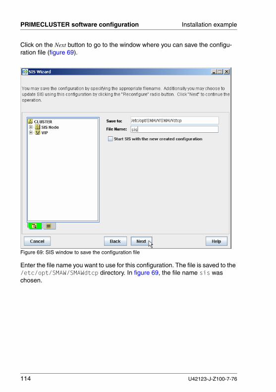
114 U42123-J-Z100-7-76
PRIMECLUSTER software configuration Installation example
Click on the Next button to go to the window where you can save the configu-ration file (figure 69).
Figure 69: SIS window to save the configuration file
Enter the file name you want to use for this configuration. The file is saved to the /etc/opt/SMAW/SMAWdtcp directory. In figure 69, the file name sis was chosen.

U42123-J-Z100-7-76 115
Installation example PRIMECLUSTER software configuration
You can also choose to start SIS immediately with the new configuration file by checking Start SIS with new created configuration and selecting Rebuild. Click on shasta2 to be the primary database node and shasta1 to be the backup database node (figure 70).
Figure 70: Starting SIS with new configuration
Click on the Next button to save the file.

116 U42123-J-Z100-7-76
PRIMECLUSTER software configuration Installation example
The next window confirms that the file was saved and SIS restarted (figure 71).
Figure 71: Results of SIS save/restart operation
Click on the Finish button to end the SIS Wizard. Now that SIS has been configured, you are ready to configure RMS.

U42123-J-Z100-7-76 117
Installation example PRIMECLUSTER software configuration
7.4.5 PCS example
This section gives an example of creating an application using PCS. A similar configuration example is provided in the PRIMECLUSTER Reliant Monitor Services (RMS) with PCS (Solaris, Linux) Configuration and Administration Guide.
This example uses a simple configuration with a single command line subappli-cation to illustrate the PCS configuration process. The example includes the following steps:
● Starting PCS
● Selecting a node for the PCS session
● Entering a configuration name
● Selecting nodes
● Choosing an application template
● Changing the application name
● Selecting nodes for the application
● Configuring a subapplication
● Saving the configuration
● Activating the configuration

118 U42123-J-Z100-7-76
PRIMECLUSTER software configuration Installation example
7.4.5.1 Starting PCS
In the Cluster Admin initial window, select the rms&pcs tab. The RMS adminis-tration window appears (figure 72).
Figure 72: RMS administration window
From the Tools menu, select PRIMECLUSTER Configuration Services (PCS) (figure 73).
Figure 73: Invoking PCS

U42123-J-Z100-7-76 119
Installation example PRIMECLUSTER software configuration
7.4.5.2 Selecting a node for the PCS session
You will be prompted to choose a node where you will start this PCS session (figure 74).
Figure 74: Selecting a node for PCS session
By default, you will connect to the same node where you started Cluster Admin. If you’re modifying a configuration stored on a different node, you should check the box of that node instead. Click the OK button to connect to the desired node.

120 U42123-J-Z100-7-76
PRIMECLUSTER software configuration Installation example
7.4.5.3 Creating a new configuration
To create a new configuration, type the new name directly into the Configuration Name input box (figure 75).
Figure 75: Entering a new configuration name
Click Next to proceed.

U42123-J-Z100-7-76 121
Installation example PRIMECLUSTER software configuration
7.4.5.4 Selecting nodes
Your first task is to select the nodes to be managed by the new configuration. You should include any node that might be used to run the applications that you want to make highly available (figure 76).
Figure 76: Selecting nodes
Nodes that appear in the right-hand Selected Nodes column will be included in the configuration. By default, PCS automatically detects all online nodes in the local cluster and enters them in the Selected Nodes column. Any nodes that appear in the left-hand Available Nodes column are not included in the present configu-ration.
In most cases, the Available Nodes column is initially empty, but you may want to include machines that are members of another cluster, or currently offline, and therefore not automatically detected by PCS. In such cases, you can manually add nodes to the left-hand Available Nodes column by typing each node name in the Enter Node to be added box and then clicking the + button.
I The list of nodes can also be modified after the configuration has been created.

122 U42123-J-Z100-7-76
PRIMECLUSTER software configuration Installation example
You can exclude one or more available nodes in the configuration by moving their names to the left-hand Available Nodes column with the arrow buttons. The << (double left arrow) button moves all selected nodes to the Available Nodes column, and the >>(double right arrow) button moves all available nodes back to the Selected Values column. To move a single node, use the > (single right arrow) button or the < (single left arrow) button.
In this example, keep shasta1RMS and shasta2RMS in the Selected Values column. Click Next to proceed.
PCS displays the Configuration Start window (figure 77).
Figure 77: Configuration Start window

U42123-J-Z100-7-76 123
Installation example PRIMECLUSTER software configuration
7.4.5.5 Viewing the configuration tree
The configuration name appears in the left pane at the top of the tree. In a new configuration it will initially be the only item, marked as consistent with a blue status icon. Other items such as applications, subapplications, configuration groups, and instances will appear as PCS guides you through the configuration process.
If the real-time consistency check option is selected, items in the tree will change state as you add applications and subapplications:
● A blue status icon indicates a consistent state—all required information for the item (and its subtree, if any) has been entered.
● A red status icon indicates an inconsistent state—the item or a member of its subtree has at least one required parameter or selection missing.
● An orange status icon indicates an optional item—usually a subapplication that is not required by the parent application.
If you save the configuration before it is consistent, PCS will display a warning in the right-hand user input pane.
7.4.5.6 Choosing the application template
You are now ready to configure an application for your configuration. PCS uses templates to make the configuration process easier; in this example, we will make a configuration for an application using the Generic application template.
I The templates that appear in the drop down list depend on the installed software.

124 U42123-J-Z100-7-76
PRIMECLUSTER software configuration Installation example
From the Configuration Start window, leave Generic for the Template Name in the drop-down list (figure 78).
Figure 78: Choosing the application template

U42123-J-Z100-7-76 125
Installation example PRIMECLUSTER software configuration
7.4.5.7 Changing the application name
The Change Application Name window appears (figure 79).
Figure 79: Changing the application name
Note that the tree in the left pane now displays items that are automatically provided by the Generic template as follows:
● The item currently being configured has its name highlighted in light blue, and its associated parameters are displayed in the right-hand user input pane.
● The items marked with red status icons are inconsistent, which means that you must define some additional parameters before RMS can run the config-uration.
By default, PCS automatically names the first application App0. This appears as the first item below the configuration name in the tree and in the corresponding right pane. You can change it by entering any valid name in the text input box.
For our example, accept the default name and click Next to continue.

126 U42123-J-Z100-7-76
PRIMECLUSTER software configuration Installation example
7.4.5.8 Viewing template information
The Processing Application window appears, which displays template-specific information (figure 80). No user input is required here. Click the Next button to continue.
Figure 80: Viewing Generic template information

U42123-J-Z100-7-76 127
Installation example PRIMECLUSTER software configuration
7.4.5.9 Selecting nodes for the application
You must specify a list of nodes where the current application will run. You can choose any or all of the nodes you selected earlier for this configuration (figure 81).
Figure 81: Available nodes for an application

128 U42123-J-Z100-7-76
PRIMECLUSTER software configuration Installation example
Add the nodes shasta1RMS and shasta2RMS to the Selected Values column (figure 82).
Figure 82: Selected nodes for an application
Click Next to proceed.
7.4.5.10 Setting application parameters
Click Next to accept the defaults and continue to the next item in the tree.

U42123-J-Z100-7-76 129
Installation example PRIMECLUSTER software configuration
7.4.5.11 Configuring a subapplication
You advance to the first subapplication in the template. Note that the first two items in the application subtree are now marked as consistent with blue status icons. In this example, we will configure the CommandLine subapplication. Check the Configure this subapplication checkbox in the right pane (figure 83).
Figure 83: Beginning a subapplication configuration
Because this is the first instance of this subapplication, PCS advances automat-ically to the subapplication parameters window (figure 84).
figure 84 uses the following scripts to illustrate how the scripts work:
● Start command: ‘/bin/touch /tmp/HelloWorld’ (creates a file)
● Stop command: ‘rm -f /tmp/HelloWorld’ (removes the file)
● Detector command: ‘ls /tmp/HelloWorld’ (determines if the file exists)

130 U42123-J-Z100-7-76
PRIMECLUSTER software configuration Installation example
The operations for the CommandLine subapplication are executed in the following order:
1. The Detector Command is first executed at RMS startup and repeated at regular intervals; by default the interval is 10 seconds. The detector command should return a zero status code when the application is online, and a non-zero status code when the application is offline.
In this example, ‘ls /tmp/HelloWorld’ will return a zero status code if the file exists, and non-zero otherwise. Assuming the file does not exist when RMS starts up, the detector will initially return a non-zero status. RMS inter-prets this to mean the subapplication is offline.
2. The Start Command is executed whenever the application receives a directive to go online. This script is executed automatically if the application’s AutoStartUp option is set to Yes. If AutoStartUp is set to No, the default, the script will be executed when you use the Cluster Admin GUI or the hvswitch command to manually instruct the application to go online. In any case, the start command should return a zero status code to indicate successful completion, and a non-zero status code otherwise.
In this example, ‘/bin/touch /tmp/HelloWorld’ creates the file specified in the detector script and returns a zero status code. Subsequent execution of the detector will return a zero status code as long as the file is present. RMS interprets this to mean the subapplication is online.
3. The Stop Command is executed when a fault occurs or when the application is to be taken offline. During normal operation, the application may be automatically taken offline on the local node before RMS switches it to another node; the application may also be taken offline manually via the GUI or CLI.
In this example, ‘rm -f /tmp/HelloWorld’ removes the file specified in the detector script. Subsequent executions of the detector return a non-zero status code, which RMS interprets to mean the subapplication is offline.
Note that the file could have been deleted manually by the operator, in which case the detector would also return a non-zero status. However, since this happened without an intervening Stop Command, RMS would interpret this as a fault, and it would initiate its standard recovery procedure.

U42123-J-Z100-7-76 131
Installation example PRIMECLUSTER software configuration
The CommandLine subapplication is now consistent, as shown by its blue status icon (figure 84).
Figure 84: CommandLine subapplication parameters
Click Next to continue.

132 U42123-J-Z100-7-76
PRIMECLUSTER software configuration Installation example
The focus (light blue highlight) in the left pane has advanced to the next subap-plication (figure 85). To configure additional subapplications, you would move the focus in the configuration tree, check Configure this subapplication in the right pane, and click Next. You can also use the Skip button to proceed with the config-uration without adding additional applications or subapplications at any stage.
Figure 85: Additional subapplications
In our example, we will skip all other subapplications.

U42123-J-Z100-7-76 133
Installation example PRIMECLUSTER software configuration
7.4.5.12 Checking application consistency
The blue status icon for the nodes (shasta1RMS and shasta2RMS), the appli-cation (App0), and the subapplication (Command Line) indicates that they are consistent. The other subapplications are optional and are not used in this configuration, so their status icons are orange. Therefore, the demo configu-ration tree is also consistent (figure 86).
Figure 86: Consistent configuration tree

134 U42123-J-Z100-7-76
PRIMECLUSTER software configuration Installation example
7.4.5.13 Saving the configuration
To save the configuration with the current name, you can use File –> Save from the menu at any time (figure 87). You can clone the configuration by using File –> Save As, which saves the configuration with a different name.
Figure 87: Saving a configuration with the menu
figure 88 appears after the configuration has been saved successfully. Click Next to continue.
Figure 88: Message after successful save operation
7.4.5.14 Activating the configuration
When the configuration is consistent, you can activate it. Activation consists of the following phases:
● Generation—Generates a complete RMS configuration file, configname.us, which is stored on the local machine.
● Distribution—Copies the configuration file, along with the required detectors and scripts, to all the nodes specified in the configuration.
● Activation—Marks the configuration as the one to load when RMS restarts.

U42123-J-Z100-7-76 135
Installation example PRIMECLUSTER software configuration
I Before you activate a configuration, you must stop RMS on all nodes in the configuration. By default, RMS will use the most recently activated configuration the next time it starts.
To activate the configuration use Tools –> Activate-> Update (figure 89).
Figure 89: Activating a configuration
When the activation phase completes, the status appears in a message window (figure 90).
Figure 90: Activation succeeded
Next, you can start RMS from the Cluster Admin main window by selecting Tools -> Start RMS.
This PCS configuration example is only a general product demonstration. For a more complete description of PCS options, refer to the PRIMECLUSTER Reliant Monitor Services (RMS) with PCS (Linux) Configuration and Administration Guide.


U42123-J-Z100-7-76 137
8 PRIMECLUSTER upgradeThis chapter describes upgrading PRIMECLUSTER from versions 4.2A00 to version 4.2A20.
I If you are upgrading from a version other than 4.2A00, you must first upgrade to 4.2A00 before continuing. To upgrade to 4.2A00, follow the upgrade instructions as described in the PRIMECLUSTER Installation Guide (Linux) for PRIMECLUSTER 4.2A00.
Upgrading in a clustered environment can have serious implications and should be carefully planned. There may be applications for which this procedure does not work. Contact your Fujitsu Technology Solutions sales team for information concerning specific application updates.
This chapter discusses the following:
● The section “Overview” describes the rolling upgrade process.
● The section “Cautions” informs you about possible risks during a rolling upgrade.
● The section “Preparation” discusses steps to be considered before doing an upgrade.
● The section “Upgrading SIS satellite nodes” describes how to upgrade the SIS satellite nodes during the rolling upgrade. If you are not using SIS satellite nodes, you can skip this section.
● The section “Performing the rolling upgrade” contains instructions for upgrading each node of the cluster.
● The section “Post-installation” details the post-installation modifications needed to complete the upgrade.
● The section “Conclusion” completes the discussion on the rolling upgrade process.

138 U42123-J-Z100-7-76
Overview PRIMECLUSTER upgrade
8.1 Overview
A rolling upgrade in a PRIMECLUSTER environment proceeds by taking one node at a time out of the cluster and upgrading the PRIMECLUSTER software on that node. When the upgrade on that node is complete, it is rejoined to the cluster. This process is repeated until all the nodes in the cluster are upgraded. This method of upgrade ensures minimum downtime and minimizes the impact on the availability.
I If the cluster includes software from PRIMECLUSTER CD2, such as Global Disk Services (GDS), Global File Services (GFS), and Global Link Services (GLS), then the rolling-upgrade procedures described in this chapter do not apply.
Refer to the chapter “Appendix—Product sets and packages” for the lists of PRIMECLUSTER packages on the PRIMECLUSTER CDs. Only PRIMECLUSTER products from CD1 are supported with the rolling upgrade described in this chapter.
8.2 Cautions
V Caution
A rolling upgrade of PRIMECLUSTER requires that you follow these instructions precisely. Omitting a step might cause loss of availability of an application, or in severe cases, you might lose cluster integrity and corrupt your application data. Planning the details of a rolling upgrade is strongly recommended.
V Caution
Do not make any changes in the configuration until all PRIMECLUSTER packages have been updated on all nodes. The new PRIMECLUSTER packages are compatible with the old PRIMECLUSTER packages, but the old PRIMECLUSTER packages might not necessarily understand the configuration of the new PRIMECLUSTER packages. The cluster might lose functionality if changes are made in the configuration while running two versions of PRIMECLUSTER. This would mean that high availability is not guaranteed.

U42123-J-Z100-7-76 139
PRIMECLUSTER upgrade Preparation
V Caution
Do not attempt to configure and activate new features in PRIME-CLUSTER until all cluster nodes are upgraded. Configuration and activation for the new features is not part of the rolling upgrade process. Once the entire cluster is upgraded, new features can be configured and activated.
V Caution
Do not use Cluster Admin or Web-Based Admin View until all of the nodes in the cluster are upgraded successfully. If these products are used during the upgrade process, both cluster integrity and high avail-ability could be lost.
8.3 Preparation
This section provides you with preparation and planning steps that will help you to achieve a safe and smooth upgrade.
A software upgrade in a clustered environment is more complex because the expectations are higher than for a stand-alone machine. For a stand-alone (non-clustered) machine, you shut down your applications, perform an update, and restart the applications. In a clustered environment, it is assumed that the appli-cation can remain running while the update is performed.
To accomplish this, during an update a cluster will have two versions of the cluster software installed and running at the same time, one version on each of two sub-clusters. During this time, the operations that can be performed on the cluster are highly restricted.
8.3.1 Verify cluster upgrade capability
You should verify the installed PRIMECLUSTER packages on each node to see if products from CD2 are installed. The cluster cannot be upgraded with the procedure described in this chapter if one of these products is installed.

140 U42123-J-Z100-7-76
Preparation PRIMECLUSTER upgrade
Use the cluster_check command to identify if products from CD2 are installed. Get a list of products from CD2 by loading the PRIMECLUSTER 4.2A20 CD1 into the CD-ROM drive and then executing the following:
1. # mount <CD1>
<CD1> is the CD-ROM mountpoint.
2. # cd <CD1>/Tool
3. # ./cluster_check
If any of the above commands return rows of data, then software from CD2 is installed on the node, and If any package in the category GDS/LDS, GFS/LFS, or GLS is shown to be installed, then the rolling upgrade described in this chapter is not supported.
8.3.2 Backup
In the unlikely case that something should go wrong during the upgrade procedure and a restoration needs to be performed, it is important to have a backup made before the upgrade procedure has started. Therefore, it is recom-mended that you make a complete backup, including application production data and the PRIMECLUSTER configuration.
Refer to the documentation of the application software on how to backup the production data, and be aware that if you keep the application running during the upgrade, your production data can diverge from the backup.

U42123-J-Z100-7-76 141
PRIMECLUSTER upgrade Preparation
table 10 lists the PRIMECLUSTER configuration files.
Packages Configuration files Notes
SMAWcf /etc/cip.cf /etc/default/cluster/etc/default/cluster.config/var/adm/cfreg.data
SMAWsf /etc/opt/SMAW/SMAWsf/*.cfg/opt/SMAW/SMAWsf/etc/SA_wtinps.ver
Actual files may vary, depending on the installed SAs
SMAWdtcp /etc/opt/SMAW/SMAWdtcp/* SIS configu-ration files
webview /opt/FJSVwvbs/etc/webview.cnf Web-Based Admin View configu-ration file
SMAWRrms /etc/exports1
/etc/group1/etc/hosts1/etc/host.conf1/etc/nsswitch.conf1/etc/passwd1/etc/fstab1/opt/SMAW/SMAWRrms/etc/*/opt/SMAW/SMAWRrms/bin/hvenv.local/opt/SMAW/SMAWRrms/bin/hvgdstartup/opt/SMAW/SMAWRrms/bin/wizard.d/contrib/*/opt/SMAW/SMAWRrms/build/2
1 System files modified for PRIMECLUSTER2 Files, directories, and subdirectories to be saved
Table 10: PRIMECLUSTER configuration files

142 U42123-J-Z100-7-76
Preparation PRIMECLUSTER upgrade
8.3.3 Upgrade preparation
I Before starting the upgrade process, verify that you have enough available disk space for the new PRIMECLUSTER upgrade.
To verify that the upgrade to PRIMECLUSTER will not cause any problems, you need to verify the upgrade capability, and you might need to save or modify the existing cluster configuration. The following steps need to be done before rolling upgrade:
1. Install patches
2. Decide in which order to upgrade the nodes
3. RMS preparation
4. Save Web-Based Admin View configuration file
8.3.3.1 Install patches
For compatibility between nodes in the cluster during rolling upgrade, you need to install one or more patches on all the nodes prior to the rolling upgrade process. Please install the latest available patch level for all PRIMECLUSTER products. Patches may be available to fix problems which were unknown at the time this text was written, but which are needed for rolling upgrade. Not installing these patches could cause incompatibility, preventing the cluster from working properly and, in severe cases, result in data corruption.
The latest patch level can be obtained through your support staff.
V Important
After performing section “Shutdown node A” and before installing the new PRIMECLUSTER software in section “Upgrading the software on node A”, ensure that the operating system (OS) is on a supported level for the new PRIMECLUSTER software. Refer to the CF Release Notice for details on the supported OS level (refer to the section “PRIMECLUSTER documentation”).
8.3.3.2 Decide the node upgrade order
From the existing cluster, you need to select which node(s) should remain running and which single node will be taken out for upgrading. While deciding on the node order, keep the following in mind:

U42123-J-Z100-7-76 143
PRIMECLUSTER upgrade Preparation
● Scalable Internet Services (SIS) satellite nodes—Upgrade all SIS satellite nodes before upgrading any core SIS nodes.
● Scalable Internet Services (SIS)—Ensure that the non-database nodes are upgraded first. The backup database node or nodes are upgraded next. The database node will be upgraded last.
The dtcpstat -N command displays the status of every node in the cluster configured for SIS. Entering the dtcpstat -N command results in output similar to the following:
Type refers to the type of node. The meaning of the output for Type is as follows:
I State refers to the state of SIS on that node, not the state of the node.
● Third-party application software—Ensure that one or more of the remaining nodes in the cluster have all parts of the third-party software. Refer to the appropriate third-party application software documentation for more details.
8.3.3.3 RMS preparation
To safely upgrade RMS, you should perform the following steps:
1. Backup the hvipalias file
2. Make the RMS settings consistent
Id Name Type State
0 shasta1 DGS UP
1 shasta2 S UP
D Database node
d Backup database node
G Gateway node
S Service node

144 U42123-J-Z100-7-76
Preparation PRIMECLUSTER upgrade
Backing up the hvipalias file
The upgrade procedure may overwrite the /opt/SMAW/SMAWRrms/etc/hvipalias file. Please keep a copy of this file in a convenient location. You need to merge it later with the new hvipalias file that will be created when you install the new packages.
Make the RMS settings consistent
For RMS to work during rolling upgrade, the RMS settings need to be consistent during upgrade on all the nodes in the cluster. To make the RMS settings consistent, you need to have environment variable entries in the following file on all cluster nodes:
/opt/SMAW/SMAWRrms/bin/hvenv.local
These environment variable entries override the default settings. The values of the environment variables are specified as export directives. The following is an example of an export directive:
export HV_USE_ELM=0
For details on these environment variables and their settings, refer to the PRIMECLUSTER Reliant Monitor Services (RMS) with Wizard Tools (Solaris, Linux) Configuration and Administration Guide or the PRIMECLUSTER Reliant Monitor Services (RMS) with PCS (Solaris, Linux) Configuration and Administration Guide.
8.3.3.4 Save Web-Based Admin View configuration file
During the rolling upgrade, the existing Web-Based Admin View software is removed by cluster_uninstall. Therefore, on each node, you need to save the Web-Based Admin View configuration with the wvEnvsave command:
/etc/opt/FJSVwvbs/etc/bin/wvEnvsave backup-file
backup-file is the name of the file to which the Web-Based View's environment variables will be saved.

U42123-J-Z100-7-76 145
PRIMECLUSTER upgrade Upgrading SIS satellite nodes
The following is an example of the wvEnvsave command with output:
# /etc/opt/FJSVwvbs/etc/bin/wvEnvsave /mydir/Base_GUIs.save
16 blocks
wvEnvsave: all files saved successfully into '/mydir/Base_GUIs.save'
8.4 Upgrading SIS satellite nodes
If you are not using SIS satellite nodes, you can skip this section. If you are using SIS satellite nodes, you need to upgrade the Satellite nodes before upgrading the rest of the cluster nodes. For PRIMECLUSTER 4.2A20, SIS satellite nodes are only supported on nodes running Windows 2003 Server.
Upgrade the SIS satellite nodes by performing the following steps:
1. Choose Start-> All Programs-> SMAWssat-> uninstall.
2. Reboot the system.
3. Install the SMAWssat package.
After the SMAWssat package removes successfully, you can install the new SMAWssat package by following the same procedure as a new installation. Refer to the chapter “SIS Satellite node installation” for details on the instal-lation process.
I Install any current valid patches for the new software after the installation of each satellite node is completed.
8.5 Performing the rolling upgrade
This section contains instructions for upgrading each node of the cluster.
The first node to be upgraded is referred to as node A. This discussion also assumes that all RMS applications are switched over to a single node, referred to as node B. In general, the RMS applications can be switched over to one or more nodes.
To perform a rolling upgrade on node A:
1. Switch RMS applications from node A to node B

146 U42123-J-Z100-7-76
Performing the rolling upgrade PRIMECLUSTER upgrade
2. Shutdown node A (node A is out of the cluster)
3. Upgrade node A software to the latest PRIMECLUSTER version
4. Rejoin node A to the cluster
Repeat the steps above for each node in the cluster.
When all of the nodes are upgraded to the latest PRIMECLUSTER software, follow the post-installation steps to complete the rolling upgrade process.
8.5.1 Switching RMS applications
I The Cluster Admin GUI must not be used during rolling upgrade. Use the command line for cluster administration.
Before shutting down RMS, determine the applications controlled by RMS that need to be switched over to node B. Switch RMS applications from node A to node B as follows:
1. Run the following command on node A to list applications to be switched:
# hvdisp -T userApplication
In the output, resources of type userApplication without a HostName that are not offline are the RMS applications currently running on node A as in the following example:
Local System: shasta1RMSConfiguration: /opt/SMAW/SMAWRrms/build/websvr.us
Resource Type HostName State -------------------------------------------------------------app1 userApplication Onlineapp2 userApplication Online
2. Switch applications to node B:
# hvswitch userApplication SysNode
userApplication is the name of your RMS application.
SysNode is the CF name of node B.

U42123-J-Z100-7-76 147
PRIMECLUSTER upgrade Performing the rolling upgrade
The following example shows how an application can be switched from shasta1 to shasta2:
shasta1# hvswitch app1 shasta2
shasta1# hvswitch app2 shasta2
For more details on how to switch an application, refer to the PRIME-CLUSTER Reliant Monitor Services (RMS) with Wizard Tools (Solaris, Linux) Configuration and Administration Guide or the PRIMECLUSTER Reliant Monitor Services (RMS) with PCS (Solaris, Linux) Configuration and Administration Guide.
3. Verify that applications under RMS control from node A are moved to node B with the following command:
# hvdisp -T userApplication
For example, specify the following command from shasta1:
shasta1# hvdisp -T userApplication
The output appears as follows:
Local System: shasta1RMSConfiguration: /opt/SMAW/SMAWRrms/build/websvr.us
Resource Type HostName State -------------------------------------------------------------app1 userApplication Offline app1 userApplication shasta2RMS Onlineapp2 userApplication Offline app2 userApplication shasta2RMS Online
All RMS applications have been switched over to shasta2 as shown by the output because the resources of type userApplication without a HostName are Offline and the resources of type userApplication on shasta2RMS are Online.
In the section “Shutdown node A” that follows, RMS applications still running on node A will be taken Offline without switching over to node B.

148 U42123-J-Z100-7-76
Performing the rolling upgrade PRIMECLUSTER upgrade
8.5.2 Shutdown node A
All of the PRIMECLUSTER products and the applications controlled by PRIME-CLUSTER have to be stopped before the CF driver can be unloaded.
1. Stop any third-party applications that do not need to be moved to node B. Refer to your application software documentation on how to stop the appli-cation.
2. Shutdown RMS locally on node A with the following command:
# hvshut -l
This shuts down RMS and all the applications controlled by RMS on node A only.
3. If SIS services are running on node A, issue the following command on node A:
# dtcpadmin -u
This will shutdown SIS on node A.
4. Unload rcmib on node A:
# /opt/SMAW/SMAWrcmib/dep/S99rcmib.cvagt unload
5. Stop all PRIMECLUSTER service-layer products that use CF on node A with the following command on node A:
# cd /opt/SMAW/SMAWcf/dep
# ./master unload
If you see the following output, the unload was successful:
CF: All modules successfully unloaded
6. Verify that all PRIMECLUSTER service-layer products that use CF are stopped on node A by executing the following commands:
# cd /opt/SMAW/SMAWcf/dep
# ./master check
# echo $?
If the exit code displayed with echo $? does not equal 0, there is still a dependency on CF, and CF can not be unloaded.

U42123-J-Z100-7-76 149
PRIMECLUSTER upgrade Performing the rolling upgrade
Refer to the layered-product software documentation on how to stop processes that are still attached to CF.
7. Unload CF on node A by executing the following command:
# cfconfig -u
This removes the current node from the cluster, but keeps the configuration. If this command fails, then some PRIMECLUSTER product or third-party software is still using CF. Stop this layered-product software first (refer to Steps 5 and 6).
8. Stop the Shutdown Facility as follows:
# /etc/init.d/SMAWsf stop
I In the hvdisp output of the other cluster nodes, Node A will be displayed with the State Offline and the StateDetails Not Joined.
8.5.3 Upgrading the software on node A
To upgrade the software on node A, perform the following steps:
1. Manually remove some PRIMECLUSTER packages
2. Remove the remaining old PRIMECLUSTER packages
3. Verify supported OS level
4. Remove any persisting PRIMECLUSTER kernel drivers
5. Install the new PRIMECLUSTER packages
8.5.3.1 Manually removing PRIMECLUSTER packages
If one or more of the following packages is installed, it must be removed manually:
● SMAWRhv-db
● SMAWRhv-co
● SMAWRhv-de
● SMAWRhv-ns
● SMAWRhv-ws
● SMAWRhv-xp

150 U42123-J-Z100-7-76
Performing the rolling upgrade PRIMECLUSTER upgrade
To check whether a package is installed, use the following command:
# rpm -q package_name
If package_name is installed, your output is similar to:
package_name-4.2A00-11
If package_name is not installed, your output is:
package package_name is not installed
To manually remove the installed package:
# rpm -e package_name
8.5.3.2 Removing the remaining old PRIMECLUSTER packages
Now use cluster_uninstall to remove the remaining PRIMECLUSTER packages. Load the PRIMECLUSTER CD1 of the currently running PRIME-CLUSTER version into the CD-ROM drive and execute the following:
1. # mount /<CD1>
<CD1> is the CD-ROM mountpoint.
2. # cd <CD1>/Tool
3. # ./cluster_uninstall
You will see output similar to the following:
Are you sure to remove PRIMECLUSTER from your system (y or n)?
Reply by entering the letter y to proceed.

U42123-J-Z100-7-76 151
PRIMECLUSTER upgrade Performing the rolling upgrade
Output similar to figure 91 appears.
Figure 91: cluster_uninstall output
The cluster_uninstall removal of PRIMECLUSTER packages is complete when the following message is output:
The uninstallation finished successfully.
I Not all PRIMECLUSTER configurations have all PRIMECLUSTER packages installed. Therefore, the output of cluster_uninstall might show fewer or additional packages.
8.5.3.3 Removing persisting PRIMECLUSTER kernel drivers
To remove persisting PRIMECLUSTER kernel drivers (for example, SIS and RCVM), reboot the system with the following command:
# init 6
8.5.3.4 Verify supported OS level
PRIMECLUSTER has now been removed from your system, while the PRIME-CLUSTER configuration remains untouched. The next step is to ensure that the OS is on a supported level for the new PRIMECLUSTER software. Refer to the CF Release Notice for details on the supported OS versions and their respective patch level. After updating the base OS, review the disk space requirements.
Uninstalling package <SMAWRhv-or> ... finishedUninstalling package <SMAWRhv-dm> ... finishedUninstalling package <SMAWRhv-r3> ... finishedUninstalling package <SMAWRhv-do> ... finishedUninstalling package <SMAWRhv-ba> ... finishedUninstalling package <SMAWRhv-to> ... finishedUninstalling package <SMAWRrms> ... finishedUninstalling package <SMAWpas> ... finishedUninstalling package <SMAWdtcp> ... finishedUninstalling package <FJSVcldbm> ... finishedUninstalling package <FJSVclapi> ... finishedUninstalling package <SMAWsf> ... finishedUninstalling package <SMAWcf> ... finishedUninstalling package <SMAWskel> ... finishedUninstalling package <SMAWrcaja> ... finishedUninstalling package <SMAWrcadm> ... finishedUninstalling package <FJSVwvmpc> ... finishedUninstalling package <FJSVwvbs> ... finishedUninstalling package <FJSVpclsnap> ... finished

152 U42123-J-Z100-7-76
Performing the rolling upgrade PRIMECLUSTER upgrade
I Some operating systems configure all interfaces with the node name. By installing a patch, the interfaces with node_nameRMS and node_namermsAI_n might be reset to the node name. Please take the appropriate action to have correct interface names.
8.5.3.5 Installing new PRIMECLUSTER packages
The installation of new PRIMECLUSTER packages follows the same procedure as a new installation. Refer to the chapter “Installation with CLI” for details on the installation process.
I Install the current valid patches for the new software once the installation on this node is completed successfully.
I If you are using SMAWrcmib, verify that the correct version of EMANATE SNMP Master Agent is installed. Refer to the SMAWrcmib readme for the supported version.
8.5.4 Joining node A back to the cluster
Perform the following when the new packages have been installed successfully:
1. If the/opt/SMAW/SMAWRrms/etc/hvipalias file is modified after the package installation, then you need to merge the file with the file you backed up earlier (in the section “Preparation”).
2. Reboot node A by using the following command:
# init 6
This will reboot the node in multi-user mode.
Node A will be part of the cluster again when the node is in multi-user mode, and all the PRIMECLUSTER software is started.
3. Start RMS and start RMS applications on node A, and switch back applica-tions to node A:
V Caution
Do not select Configuration-Activate in the RMS Wizards or Activate in PCS during a rolling upgrade (because different versions of RMS are running in the cluster).
a) Start RMS on node A (issue command on node A):

U42123-J-Z100-7-76 153
PRIMECLUSTER upgrade Performing the rolling upgrade
Depending on the RMS setting, RMS might start during reboot (HV_RCSTART=1). If RMS does not start during a reboot (HV_RCSTART=0), you can now issue the following command:
# hvcm
If the RMS configuration includes node-specific applications for node A, which do not startup during a reboot, you may start them now as follows:
# hvswitch userApplication
b) Remember that switching an application from one node to another causes a brief interruption, and should generally be avoided. Also, now that node A is upgraded, it will remain running for the remainder of the rolling upgrade. Therefore, applications switched to node A will not need to be switched again.
To switch an RMS application to node A, issue the following command on the node currently running the application:
# hvswitch userApplication SysNode
userApplication is the name of your RMS application.
SysNode is the CF name of node A.
c) Verify that applications have switched back to node A (issue command on node A):
# hvdisp -a
4. If you need to restart SIS on node A, use the following commands:
a) To verify that SIS is running on node A:
# dtcpstat -l
I The SIS administrative commands to display cluster wide SIS values only work on nodes that run the same version as the SIS database node.
SIS is not running on this node if this command returns the following:
node does not exist in the nodename space
b) If SIS is not running, start SIS on node A:
If node A is not a database node and not a backup database node:
# dtcpadmin -s

154 U42123-J-Z100-7-76
Post-installation PRIMECLUSTER upgrade
If node A is a database node or a backup database node:
# dtcpadmin -c config_file
config_file is the file where SIS configuration is saved.
5. Start any applications not under RMS control manually.
8.5.5 Upgrading the next node
At this point, node A has rejoined the cluster with the new PRIMECLUSTER software. All applications are running on node A.
Return to the section “Performing the rolling upgrade” to upgrade the next node until all the nodes in the cluster are upgraded.
After all the nodes have been upgraded to the latest PRIMECLUSTER software, you need to adjust the configuration to complete the rolling upgrade process, as described in the following section.
8.6 Post-installation
All of the nodes in the cluster are now running the upgraded PRIMECLUSTER software, but with only the earlier software features. The following modifications are needed to complete the upgrade and access the new features:
● Restoring the Web-based Admin View configuration
● Establishing an RMS configuration for the new version of RMS
8.6.1 Restoring Web-Based Admin View configuration
Restore the Web-Based Admin View configuration as follows:
1. Web-based Admin View needs to be stopped before performing the resto-ration. Perform the following on all the nodes to stop Web-based Admin View:
# /etc/init.d/fjsvwvcnf stop
# /etc/init.d/fjsvwvbs stop

U42123-J-Z100-7-76 155
PRIMECLUSTER upgrade Post-installation
2. Use the wvEnvload command to restore the previously saved Web-Based Admin View configuration (refer to the section “Save Web-Based Admin View configuration file”). The configuration should be done on every node and only when Web-Based Admin View is not running. After the restoration is done on all nodes, then Web-Based Admin View may be restarted on the nodes. The syntax is as follows:
/etc/opt/FJSVwvbs/etc/bin/wvEnvload backup-file
backup-file is the name of the file containing the previously saved configu-ration
The following is an example of the wvEnvload command:
# /etc/opt/FJSVwvbs/etc/bin/wvEnvload /mydir/Base_GUIs.save
16 blocks4 blockswvEnvload: all files restored successfully.
3. Web-based Admin View can be started when all the PRIMECLUSTER software has been upgraded successfully on all the nodes. Perform the following command on all the nodes:
# /etc/opt/FJSVwvbs/etc/bin/wvCntl restart
# /etc/init.d/fjsvwvcnf restart
This starts Web-based Admin View on all the nodes in the cluster.
I While performing the wvCntl restart you might see a message on the console ending in vip: vip_ioctl: default UNKNOWN
This message is only for informational purposes and does not indicate an error condition within this context.
8.6.2 Configuring the new RMS version
The new features in PRIMECLUSTER cannot be accessed until a configuration for the new RMS version is established, and the RMS configuration is regen-erated, redistributed, and restarted. RMS must be shutdown without stopping the application controlled by RMS, and, therefore, failovers are not supported during this procedure. However, it is highly recommended that you perform this step as soon as possible.
Establish, regenerate, redistribute, and restart an RMS configuration for the new RMS version as follows:

156 U42123-J-Z100-7-76
Post-installation PRIMECLUSTER upgrade
WT configuration
1. Execute the following command on one node in the cluster to shutdown RMS clusterwide:
# hvshut -A
This shuts down RMS, but leaves the applications controlled by RMS running.
2. Execute the following command on any node to invoke the RMS Wizard:
# hvw
With the RMS wizard, select Configuration-Activate to regenerate and redis-tribute RMS with the new configuration.
3. Execute the following command on any node to restart RMS on all nodes:
# hvcm -a
PCS configuration
1. Execute the following command on one node in the cluster to shutdown RMS clusterwide:
# hvshut -A
This shuts down RMS, but leaves the applications controlled by RMS running.
2. Launch the GUI by entering the following URL in a Java-enabled browser:
http://node_name:8081/Plugin.cgi
node_name is the name of a node in the cluster that you are upgrading. For example, shasta1 is the name of one of the cluster nodes in the following:
http://shasta1:8081/Plugin.cgi

U42123-J-Z100-7-76 157
PRIMECLUSTER upgrade Post-installation
This brings up the Web-Based Admin View main window (figure 92).
Figure 92: Cluster Admin start-up window
Enter root in the User name field and the root password and click on OK.

158 U42123-J-Z100-7-76
Post-installation PRIMECLUSTER upgrade
3. Click on the Global Cluster Services button and the Cluster Admin button appears (figure 93).
Figure 93: Cluster Admin top window
Click on the Cluster Admin button.
4. The Choose a node for initial connection window appears (figure 94).
Figure 94: Choosing an initial node
Choose a node and click Ok.

U42123-J-Z100-7-76 159
PRIMECLUSTER upgrade Post-installation
5. In the Cluster Admin initial window, select the rms&pcs tab. The RMS admin-istration window appears (figure 95).
Figure 95: RMS administration window
From the Tools menu, select PRIMECLUSTER Configuration Services (PCS) (figure 96).
Figure 96: Invoking PCS

160 U42123-J-Z100-7-76
Post-installation PRIMECLUSTER upgrade
6. Choose a node for this PCS session (figure 97).
Figure 97: Selecting a node for PCS session
7. Click the arrow next to the Configuration Name menu, and select a PCS configuration from the list (figure 98).
Figure 98: Selecting PCS configuration

U42123-J-Z100-7-76 161
PRIMECLUSTER upgrade Post-installation
Click Next.
8. From the Tools menu, select Activate -> All Nodes (figure 99).
Figure 99: Activating PCS configuration
When the activation phase completes, the status appears in a message window (figure 100).
Figure 100: Activation succeeded
9. Exit PCS from the main menu by selecting File -> Exit (figure 101).
Figure 101: Exiting PCS

162 U42123-J-Z100-7-76
Conclusion PRIMECLUSTER upgrade
A confirmation pop-up appears. Click OK.
10.Start RMS from the Cluster Admin main window by selecting Tools -> Start RMS (figure 102).
Figure 102: Starting RMS
8.7 Conclusion
The upgrade of the PRIMECLUSTER software is now complete. Your old PRIMECLUSTER configuration has now been upgraded to the latest PRIME-CLUSTER configuration and the new features are now available. Refer to the product Release Notice for information about the new features.
Because all of the nodes are now running the latest version of PRIME-CLUSTER, and Web-based Admin View has been upgraded as well, the cluster can now be administered using Cluster Admin.
Verify with the Acceptance Test specified in your sales agreement, that the cluster is fully operational.

U42123-J-Z100-7-76 163
9 Manual pagesThis chapter lists the online manual pages for CCBR, CF, CIP, PAS, PCS, Resource Database, RMS, RMS Wizards, SF, SIS, and Web-Based Admin View.
To display a manual page, type the following command:
$ man man_page_name
9.1 CCBR
System administration
cfbackupsave the cluster configuration information for a PRIMECLUSTER node
cfrestorerestore saved cluster configuration formation on a PRIMECLUSTER node
9.2 CF
System administration
cfconfigconfigure or unconfigure a node for a PRIMECLUSTER cluster
cfregdCF registry synchronization daemon
cfsetapply or modify /etc/default/cluster.config entries into the CF module
cftoolprint node communications status for a node or the cluster
rcqconfigconfigure or start quorum
rcqqueryget quorum state of the cluster

164 U42123-J-Z100-7-76
CIP Manual pages
9.3 CIP
System administration
cipconfig start or stop CIP 2.0
ciptoolretrieve CIP information about local and remote nodes in the cluster
File format
cip.cfCIP configuration file format
9.4 Monitoring Agent
System administration
cldevparamchanges or displays the displays the tunable operation environment for asynchronous monitoring
clmmbmonctlstarts, stops, restarts, and displays the operating system of the MMB asynchronous monitoring daemon
clmmbsetupregisters, changes, deletes, or displays MMB information
9.5 PAS
System administration
mipcstatMIPC statistics

U42123-J-Z100-7-76 165
Manual pages PCS
9.6 PCS
System administration
pcstoolModifies PCS configurations from the command line
pcscuiCharacter-based interface for PCS
pcs_reinstallUtility for re-integrating PCS with dependent products

166 U42123-J-Z100-7-76
Resource Database Manual pages
9.7 Resource Database
I To display a Resource Database manual page, add /etc/opt/FJSVcluster/man to the environment variable MANPATH.
System administration
clautoconfigexecute of the automatic resource registration
clbackuprdbsave the resource database
clexecexecute the remote command
cldeldevicedelete resource registered by automatic resource registration
clinitresetreset the resource database
clrestorerdbrestore the resource database
clsetparamdisplay and change the resource database operational environment
clsetupset up the resource database
clstartrscresource activation
clstoprscresource deactivation
clsyncfiledistribute a file between cluster nodes
User command
clgettreedisplay the tree information of the resource database

U42123-J-Z100-7-76 167
Manual pages RMS
9.8 RMS
System administration
hvassertassert (test for) an RMS resource state
hvcmstart the RMS configuration monitor
hvconfigdisplay or save the RMS configuration file
hvdispdisplay RMS resource information
hvdistdistribute RMS configuration files
hvdumpcollect debugging information about RMS
hvgdmakecompile an RMS custom detector
hvlogcleanclean RMS log files
hvrclevchange default RMS start run level
hvresetinterrupt ongoing activities and re-initialize the userApplication graph
hvsetenvmanipulate RMS rc start or AutoStartUp
hvshutshut down RMS
hvswitchswitch control of an RMS user application resource to another node
hvthrottleprevent multiple RMS scripts from running simultaneously
hvutilmanipulate availability of an RMS resource

168 U42123-J-Z100-7-76
RMS Wizards Manual pages
File formats
hvenv.localRMS local environment configuration file
9.9 RMS Wizards
RMS Wizards and RMS Application WizardsRMS Wizards are documented as html pages in the SMAWRhv-do package on the CD-ROM. After installing this package, the documen-tation is available in the following directory: /usr/doc/packages/SMAWRhv-do/wizards.en
9.10 SF
System administration
rcsdShutdown Daemon of the Shutdown Facility
sdtoolinterface tool for the Shutdown Daemon
File formats
rcsd.cfgconfiguration file for the Shutdown Daemon
SA_blade.cfgconfiguration file for Blade Shutdown Agent
SA_ipmi.cfgconfiguration file for a Intelligent Platform Management Interface Shutdown Agent
SA_rps.cfgconfiguration file for a Remote Power Switch Shutdown Agent
SA_rsb.cfgconfiguration file for Remote Service Board Shutdown Agent
SA_wtinps.cfgconfiguration file for WTI NPS Shutdown Agent

U42123-J-Z100-7-76 169
Manual pages SIS
9.11 SIS
System administration
dtcpadminstart the SIS administration utility
dtcpdstart the SIS daemon for configuring VIPs
dtcpstatstatus information about SIS
9.12 Web-Based Admin View
System administration
fjsvwvbsstop Web-Based Admin View
fjsvwvcnfstart, stop, or restart the web server for Web-Based Admin View
wvCntlstart, stop, or get debugging information for Web-Based Admin View
wvGetparamdisplay Web-Based Admin View's environment variable
wvSetparamset Web-Based Admin View environment variable
wvstatdisplay the operating status of Web-Based Admin View


U42123-J-Z100-7-76 171
10 Appendix—Important Web-Based Admin View settings
I If you are using Global Link Services, refer to the Web-Based Admin View Operation Guide to set up Web-Based Admin View in a GLS environment. Refer to the chapter “Web-Based Admin View configuration” for details on using wvconf to configure Web-Based Admin View.
Web-Based Admin View places a number of significant commands in the following directory:
/etc/opt/FJSVwvbs/etc/bin
The wvSetparam command found in this directory is used to set Web-Based Admin View environment variables. The ones most commonly used in setting up PRIMECLUSTER configurations are listed in table 11.
You can use the wvGetparam command to display the Web-Based Admin View environment variables. Refer to the chapter “Manual pages” for more infor-mation.
Parameter Possible Values
Example Description
primary-server IP address 172.25.200.4 The IP address of the primary management server.
secondary-server IP address 172.25.200.5 The IP address of the secondary management server.
Table 11: Important Web-Based Admin View environment settings

172 U42123-J-Z100-7-76
Appendix—Important Web-Based Admin View settings
mip IP address or node name
172.25.200.4 or shasta1
This is the IP address or name of the local interface that Web-Based Admin View uses for communica-tions between the monitored node(s) and the management server(s). The CF Wizard uses the IP name of this interface when assigning the CF node name.
httpip IP address or node name
172.25.219.83 or shasta1
This is the IP address or name of the local interface on which Web-Based Admin View's webserver will listen for requests.
The following parameters are associated with secondary server autoselection
server-election on, off on If on, the local node is a candidate for secondary server automatic migration.
server-ha on, off on If set to on on the primary management server, then automatic migration is enabled.
group-addr IP multicast or broadcast address
231.25.219.83 This is the IP group address used in the automatic migration process.
Parameter Possible Values
Example Description
Table 11: Important Web-Based Admin View environment settings

U42123-J-Z100-7-76 173
Appendix—Important Web-Based Admin View settings
I When Web-Based Admin View is initially installed, the IP addresses of the primary and secondary management servers (given by primary-server and secondary-server, respectively) are automatically set to the IP address of the local node. This, in effect, configures the local node to be the primary management server. However, in a clustered environment, all the nodes in the cluster must have the same primary management server. Thus, you must configure Web-Based Admin View on each node in the cluster. You will also need to configure the primary and secondary management server(s) if they are outside the cluster.


U42123-J-Z100-7-76 175
11 Appendix—Private network addresses
The Internet Assigned Number Authority (IANA) has defined three address ranges that are set aside for private subnets:
Subnet(s) Class Subnetmask10.0.0.0 A 255.0.0.0172.16.0.0 .. 172.31.0.0 B 255.255.0.0192.168.0.0 .. 192.168.255.0 C 255.255.255.0
Packets using addresses from these subnets are guaranteed not to be routed to public networks.
The use of these subnets is recommended for CIP addresses and for PRIVATE declarations in SIS configuration files.


U42123-J-Z100-7-76 177
Appendix—Cluster planning worksheet
12 Appendix—Cluster planning worksheet
table 12 is a blank worksheet to aid in planning your configuration. Refer to the chapter “Site planning” for information on filling out the worksheet.
Cluster Name:
Node 1 Node 2
Node Name
Cluster Interconnect
Device1 Name
Address
Device2 Name
Address
Cluster IP
Name
Address
Administrative LAN
Name
Device
IP Address
Public LAN
Name
Device
IP Address
Table 12: Cluster site planning worksheet


U42123-J-Z100-7-76 179
13 Appendix—Product sets and packages
The cluster_install command allows you to install either a group of products (known as a product set) or a single product. table 13 defines each product set.
Product set cluster_install product set
PRIMECLUSTER Enterprise Edition EE
PRIMECLUSTER HA Server HA
PRIMECLUSTER Parallel Server PS
PRIMECLUSTER Scalability Server SC
PRIMECLUSTER Enterprise Edition with PCS EE_PCS
PRIMECLUSTER HA Server with Wizard PCS HA_PCS
PRIMECLUSTER Enterprise Edition with Wizard Tools EE_WT
PRIMECLUSTER HA Server with Wizard Tools HA_WT
PRIMECLUSTER RMS package RMS-P
PRIMECLUSTER SIS package SIS-P
PRIMECLUSTER PAS package PAS-P
PRIMECLUSTER PCS Wizard Kit package PCS_WK-P
PRIMECLUSTER Global File Disk Link package GFDLS-P
PRIMECLUSTER RMS package with HV Wizard Tools RMS-P_WT
PRIMECLUSTER SIS package with HV Wizard Tools SIS-P_WT
PRIMECLUSTER PAS package with HV Wizard Tools PAS-P_WT
PRIMECLUSTER HV Wizard Kit package HV_WK-P
Table 13: Product set

180 U42123-J-Z100-7-76
Appendix—Product sets and packages
table 14, table 15, and table 16 show you what products are included in each product set on CD1.
Product Product Set
EE andEE_PCS
HA andHA_PCS
PS SC EE_WT HA_WT
PCLsnap P P P P P P
Base GUIs P P P P P P
CF P P P P P P
CCBR P P P P P P
RMS P P P P
SIS P P P
PCS P P
PAS P P P
WT P P
GLS P P P P P
GFS P P P P P
GDS P P P P P
Table 14: Product in various product sets

U42123-J-Z100-7-76 181
Appendix—Product sets and packages
Product Product Set
RMS-P SIS-P PAS-P PCS_WK-P GFDLS-P
PCLsnap P P P P P
Base GUIs P P P P
CF P P P P
CCBR P P P P
SIS P
PAS P
RMS P P P
WT
PCS P P P
PCS_WK
PKDB P
PKR3 P
PKSR P
HVKSH
WVSAT
SF
Table 15: Additional CD1 products in various product sets

182 U42123-J-Z100-7-76
Appendix—Product sets and packages
table 17 and table 18 show you what products are included in each product set on CD2.
Product Product Set
RMS-P_WT SIS-P_WT PAS-P_WT HV_WK-P
PCLsnap P P P P
Base GUIs P P P
CF P P P
CCBR P P P
SIS P
PAS P
RMS P P P
WT P P P
WKDB P
WKR3 P
WKSR P
Table 16: Additional CD1 products in various product sets
Product Product Set
EE andEE_PCS
HA andHA_PCS
PS SC EE_WT HA_WT
GDS P P P P P
GFS P P P P P
GLS P P P P P
Table 17: CD2 products in various product sets

U42123-J-Z100-7-76 183
Appendix—Product sets and packages
A row in the table represents an individual product. A column represents a product set. A check mark indicates that a product set contains the individual product for that row. For example, the SIS product is included in the product sets for the Enterprise Edition and the Scalability Server, the Scalability Server, the SIS-Package and the SIS-Package with HV Wizard Tools.
All of the product sets have an abbreviation associated with them. For example, the Enterprise Edition is known by the abbreviation EE. This abbreviation is used by the cluster_install program to designate a particular product set. For example, entering the following command would load the products associated with the Enterprise Edition product set:
# cluster_install -e EE
Refer to the section “Product set installation” for further details.
Product Product Set
RMS-P SIS-P PAS-P PCS_WK-P GFDLS-P
GDS P
GFS P
GLS P
Table 18: Additional CD2 products in various product sets

184 U42123-J-Z100-7-76
Location of packages on CDs Appendix—Product sets and packages
13.1 Location of packages on CDs
table 19 lists what packages are included in each category on CD1.
product code Packages
PCLsnap FJSVpclsnap
Base_GUIs FJSVwvbsFJSVwvmpcSMAWrcadmSMAWrcajaSMAWcj2re
CF SMAWskelSMAWhvkshSMAWcfSMAWsfFJSVclotrFJSVclapiFJSVcldbm
CCBR SMAWccbr
RCM SMAWrcmib
RMS SMAWRrmsSMAWRdfw
SIS SMAWdtcp
PAS SMAWpas
PCS SMAWpcsSMAWpcsdeFJSVpcsgdFJSVpcsgl
PCS_WK SMAWpcsdbSMAWpcsr3SMAWpcssrSMAWpcswsSMAWpcsnsSMAWpcsxp
Table 19: PRIMECLUSTER packages on CD1

U42123-J-Z100-7-76 185
Appendix—Product sets and packages Location of packages on CDs
WT SMAWRhv-toSMAWRhv-baSMAWRhv-doSMAWRhv-deFJSVhvglFJSVhvgd
HV_WK SMAWRhv-dbSMAWRhv-r3SMAWRhv-wsSMAWRhv-sr
PKDB SMAWpcsdb
PKR3 SMAWpcsr3
PKWS SMAWpcsws
PKSR SMAWpcssr
product code Packages
Table 19: PRIMECLUSTER packages on CD1

186 U42123-J-Z100-7-76
Location of packages on CDs Appendix—Product sets and packages
table 20 lists what packages are included in each category on CD2.
product code Packages
GDS FJSVsdx-cmdFJSVsdx-drvFJSVsdxma-enFJSVsdxma-jaFJSVsdxwv
GFS FJSVsfcfs-cmdFJSVsfcfs-knlFJSVsfcma-enFJSVsfcma-jaFJSVsfcwv
GLS FJSVhanet
Opt_GUIs FJSVsfcma-enFJSVsfcma-jaFJSVsfcwvFJSVsdxma-enFJSVsdxma-jaFJSVsdxwv
SNP FJSVsdx-ss
Table 20: PRIMECLUSTER packages on CD2

U42123-J-Z100-7-76 187
Appendix—Product sets and packages Installation order
13.2 Installation order
table 21 lists the PRIMECLUSTER products installation order to be used when installing more than one product by means of cluster_install.
I Refer to the section “Location of packages on CDs” for details on which packages go with each product.
Order product_code
CD Containing Product
1 Base_GUIs CD1
2 CF CD1
3 CCBR CD1
4 RMS CD1
5 SIS CD1
6 PAS CD1
7 RCM CD1
8 WT CD1
9 PCS CD1
10 GLS CD2
11 GFS CD2
12 GDS CD2
13 Opt_GUIs CD2
Table 21: Product installation order


U42123-J-Z100-7-76 189
14 Appendix—System parametersThis appendix discusses setting system parameters for PRIMECLUSTER-based configurations.
14.1 Kernel parameters for Resource Database
The default values of the Linux kernel have to be modified when the Resource Database is used. This section lists the kernel parameters that have to be changed. You could configure the kernel parameters at runtime by using the sysctl(8) utility. The following shows how to change and apply the new kernel parameters.
Change the values for SHMMAX as follows:
● Edit the file /etc/sysctl.conf
● Add the entry: kernel.shmmax = value
Change the values for the semaphore parameters as follows:
kernel.sem = value1 value2 value3 value4
Where the preceding values are defined as the following:
● value1 = value for SEMMSL
● value2 = value for SEMMNS
● value3 = value for SEMOPM
● value4 = value for SEMMNI
The Resource Manager does not use SEMMSL and SEMOPM; therefore, leave these values unchanged. The following commands show the values for these parameters prior to any modification:
● #sysctl -a | grep sem
● #sysctl -a | grep shm
The following command changes the values for the parameters:
● #sysctl -p filename (default for filename is /etc/sysctl.conf)
This command applies the values from /etc/sysctl.conf to the kernel. It is not necessary to rebuild the kernel.

190 U42123-J-Z100-7-76
Kernel parameters for Resource Database Appendix—System parameters
Use sysctl(8) to modify kernel parameters at runtime. Refer to sysctl(8) manual pages for the details on how sysctl performs.
Determining the value for SHMMAX
SHMMAX = 1048576 + the value necessary for Resource Database or more as shown by the following:
Number of resources=(a)+(b)
● (a) is the (number of shared disks) x (number of sharing nodes+1) x 2, where the number of shared disks is defined as follows:
For disk array unit, use the number of logical units (LUN).
For devices other than disk array unit, use the number of physical disks. Number of sharing nodes is defined as follows:
The number of nodes connected to the shared disks.
● (b) is the total number of local disks (number of local disks in all cluster configuration nodes).
I As kernel parameter are used for this tuning parameter, they are validated after rebooting the setup node. Therefore, if the number of nodes and logical disks increase as a result of expanding the facilities, you must perform reinstallation and then restart each cluster node. So, if a hot node or disk expansion is scheduled after installation, it is necessary to perform calculation using the number of nodes and logical disks after expansion.
Kernel parameter Amount to add for Resource Database
SEMMNI 20 or more
SEMMNS 90 or more
SEMMNU 90 or more
SHMSEG 30
SHMMNI 30
SHMMAX Refer to the section that follows.
Table 22: Kernel parameter values

U42123-J-Z100-7-76 191
Appendix—System parameters System parameters for RMS configurations
14.2 System parameters for RMS configurations
When the RMS package is installed, it will verify that the kernel tunables listed below are at or above the required minimum values. If any tunable is below the listed minimum, it will be automatically increased to the minimum value. The following system tunables are reset with the increased values in /etc/sysctl.conf:
kernel.msgmnb = 4194304kernel.msgmax = 16384kernel.msgmni = 8192
I If above requirements are already met, no change will be made to the system.
The parameters will be removed from /etc/sysctl.conf when the RMS package is removed via the rpm -e command.


U42123-J-Z100-7-76 193
15 Appendix—PRIMECLUSTER ports
table 23 lists the ports used by PRIMECLUSTER.
Int = Cluster interconnectPL = Public LANAL = Administrative LANCN = Cluster node
I Some of the ports and products mentioned in table 23 may not be available with Linux or PRIMECLUSTER.
Pro
du
ct
Lo
cati
on
UD
P
TC
P
Net
wo
rk
Sen
d/R
ecei
ve
Co
nfi
gu
rab
le
Co
mm
ents
CF (Cluster configu-ration and Data Base Manger)
Cluster node
9331 Int S, R No dcmcom
Cluster node
9379 Int S, R No dcmsync
Cluster node
9378 Int S, R No dcmlc
Cluster node
9377 Int S, R No dcmfcp
Cluster node
9375 Int S, R No dcmmst
Cluster node
9376 Int S, R No dcmevm
SIS None None
Table 23: PRIMECLUSTER ports

194 U42123-J-Z100-7-76
Appendix—PRIMECLUSTER ports
Web-Based Admin View
Cluster node
9796 None AL S, R Yes fjwv_g (FJSVwvbs group RMI)
Cluster node
9799 AL S, R Yes fjwv_c (FJSVwvbs client RMI)
Cluster node
9798 AL S, R Yes fjwv_s (FJSVwvbs server RMI)
Cluster node
9797 AL S, R Yes fjwv_n (FJSVwvbs node RMI)
Cluster node
8081* AL S, R Yes fjwv_h (FJSVwvcnf Web Port); * refer to the Section “http port number” that follows.
RMS Cluster node
8000 Int S, R No wrapper
Cluster node
9786 Int S, R Yes rmshb
PCS Cluster node
9786 Int R Yes hvutil -A API
Pro
du
ct
Lo
cati
on
UD
P
TC
P
Net
wo
rk
Sen
d/R
ecei
ve
Co
nfi
gu
rabl
e
Co
mm
ents
Table 23: PRIMECLUSTER ports

U42123-J-Z100-7-76 195
Appendix—PRIMECLUSTER ports
Changing the http port number
The initial value of the port number for access to a management server from the client Web browser is 8081.
You may need to change the Web-Based Admin View port number if Web-Based Admin View does not operate normally, or the default port number (8081) is competing with Transparent Proxy (tproxy) or other products.
SF Cluster node
2316 Int S, R Yes rcsd
Cluster node
2137-* AL S, R Yes * number of hosts
Cluster node
23 (telnet)
AL S, R No SA_wtinps
Cluster node
3173 AL S, R No SA_rsb
Cluster node
3173 AL S, R No SA_rps
SNMP Cluster node
161 Int, PL
S, R No Emanate Master Agent
Cluster node
162 Int, PL
S, R No SNMP trap receive
Cluster node
8161 Int, PL
S, R No UCD Master SNMP Agent
GLS Cluster node
1807 PL S, R No Only when GS linkage mode
GFS Cluster node
9200 Int S, R No sfcfsrm
Cluster node
9100-9199
Int, PL
S, R No sfcfs-1 - sfcfs-100
Pro
du
ct
Lo
cati
on
UD
P
TC
P
Net
wo
rk
Sen
d/R
ecei
ve
Co
nfi
gu
rabl
e
Co
mm
ents
Table 23: PRIMECLUSTER ports

196 U42123-J-Z100-7-76
Appendix—PRIMECLUSTER ports
To modify the setup, execute the following command for all management servers and monitoring nodes:
# /etc/opt/FJSVwvbs/etc/bin/wvSetport fjwv-h=<port number>
To ensure that the current port number is set to 8081, execute the following command for all management servers and cluster nodes:
# /etc/opt/FJSVwvbs/etc/bin/wvSetport fjwv-h=8081
I If you change the port number for the Web browser, ensure that you update /etc/services on all management servers and cluster nodes as well.
If a URL is registered as a bookmark, change the URL port number.
After changes are complete, restart Web-Based Admin View and access the management server. Refer also to the PRIMECLUSTER Web-Based Admin View Operation Guide for more details.

U42123-J-Z100-7-76 197
16 Appendix—TroubleshootingThis appendix contains information for troubleshooting PRIMECLUSTER.
16.1 cluster_install log files
If the cluster_install command fails, detailed information can be found in the following log files:
/var/install/logs/cluster_install.1 (log file of CD1)
/var/install/logs/cluster_install.2 (log file of CD2)
You can use these log file to determine and eliminate the cause of an installation failure.
16.2 cluster_install error messages
● Message:Installation failed.
Explanation:The installation process failed.
Solution:Refer to the ERROR message and log file, eliminate the cause of the failure, then retry the command.
● Message:ERROR: syntax error.
Explanation:Invalid command options were specified.
Solution:Check the command syntax, and start with the correct options.

198 U42123-J-Z100-7-76
cluster_install error messages Appendix—Troubleshooting
● Message:ERROR: To use this installer you will need to be the root user.
Explanation:The user is not a root user.
Solution:Only root users can execute the installer. Start the installer with root user authority.
● Message:ERROR: /tmp needs TMP_LEAST KB at least.
Explanation:The available size of /tmp file system is too small.
Solution:Please check the size of /tmp file system.
● Message:ERROR: /var needs VAR_LEAST KB at least.
Explanation:The available size of /var file system is too small.
Solution:Please check the size of /var file system.
● Message:ERROR: Please install the first CD-ROM at first.
Explanation:The product set installation should be started with CD1.
Solution:Start the product set installation with CD1.
● Message:ERROR: Package <package> of product <product> has already been installed.
Explanation:The package package has been already installed.
Solution:Use the -u (upgrade mode) or -f (force mode) options of cluster_install, or remove the package <package> with cluster_uninstall, then retry the command.

U42123-J-Z100-7-76 199
Appendix—Troubleshooting cluster_install error messages
● Message:ERROR: The installation process is running now.
Explanation:Another installation related process is running.
Solution:Wait for the termination of the other process.
I If this message displays without any other installation-related processes, you need to remove the temporal flag files /tmp/cluster_install and /tmp/cluster_uninstall, then retry the command.
● Message:ERROR: platform <platform> not supported.
Explanation:The detected platform of your system environment is not supported by the installer.
Solution:Check if the PRIMECLUSTER software supports your system environment or not.
● Message:ERROR: product set <product_set> on platform <platform> not supported.
Explanation:The product set is not supported on the platform of your system environment.
Solution:Check if the PRIMECLUSTER software you tried to install supports your system environment or not.
● Message:ERROR: no package of product set <product_set> on CDx
Explanation:Cannot find any packages of the product set on the CD that you are using.
Solution:Check the CD number of mounted PRIMECLUSTER CD, and verify that it contains the software you tried to install

200 U42123-J-Z100-7-76
cluster_install error messages Appendix—Troubleshooting
● Message:ERROR: no package of product <product> on CDx
Explanation:Cannot find any packages of the product on the CD that you are using.
Solution:Check the CD number of mounted PRIMECLUSTER CD, and verify that it contains the software you tried to install
● Message:ERROR: product <product1> and <product2> contains the same package <package>
Explanation:The products that the installer tried to install have the same package.
Solution:The installer cannot install the products each of which has the same package simultaneously. Check the options that you specified.
● Message:ERROR: failed: rpm *
Explanation:Failed to execute rpm *.
Solution:Consult the manual page for rpm(8).
● Message:ERROR: internal error: <error>
Explanation:An internal error occurred.
Solution:Please make a note of the message and contact customer support.
● Message:Please see the following log file./var/log/install/cluster_install.x
Explanation:Refer to the indicated log file to determine the cause of failure.

U42123-J-Z100-7-76 201
Appendix—Troubleshooting cluster_uninstall error messages
16.3 cluster_uninstall error messages
● Message:Uninstallation failed.
Explanation:The uninstallation process failed.
Solution:Refer to the ERROR message or log file, eliminate the cause of the failure, then retry the command.
● Message:ERROR: syntax error
Explanation:Invalid command options were specified.
Solution:Check the command syntax, and start with correct options.
● Message:ERROR: To use this installer you will need to be the root user.
Explanation:The user is not a root user.
Solution:Only root users can execute the uninstaller. Start the uninstaller with root user authority.
● Message:ERROR: /tmp needs TMP_LEAST KB at least.
Explanation:The available size of /tmp file system is too small.
Solution:Please check the size of /tmp file system.

202 U42123-J-Z100-7-76
cluster_uninstall error messages Appendix—Troubleshooting
● Message:ERROR: /var needs VAR_LEAST KB at least.
Explanation:The available size of /var file system is too small.
Solution:Please check the size of /var file system.
● Message:ERROR: CF driver is loaded.
Explanation:CF driver is loaded on the current system.
Solution:Unload the CF driver, then retry the command.
● Message:ERROR: there exists GDS object(s)
Explanation:There exists GDS objects on the current system.
Solution:Remove the GDS objects, then retry the command.
● Message:ERROR: The installation process is running now.
Explanation:Another installation-related process is running.
Solution:Wait for the termination of the other process.
I If this message displays without any other installation related processes, you need to remove temporal flag files /tmp/cluster_install and /tmp/cluster_uninstall, then retry the command.
● Message:ERROR: product set <product_set> on platform <platform> not supported.
Explanation:The product set is not supported on the platform of your system environment.

U42123-J-Z100-7-76 203
Appendix—Troubleshooting CF dependency issues
Solution:Specify a valid product set.
● Message:ERROR: product <product> on platform <platform> not supported.
Explanation:The product is not supported on the platform of your system environment.
Solution:Specify a valid product.
● Message:ERROR: failed: rpm *
Explanation:Failed to execute rpm *.
Solution:Consult the manual page for rpm(8).
● Message:ERROR: internal error: <error>
Explanation:An internal error occurred.
Solution:Please make a note of the message and contact customer support.
● Message:Please see the following log file./var/log/install/cluster_uninstall.x
Explanation:Refer to the indicated log file to determine the cause of failure.
16.4 CF dependency issues
Refer to the PRIMECLUSTER Cluster Foundation (CF) Linux® Configuration and Administration Guide for details on CF dependency issues.


U42123-J-Z100-7-76 205
Glossary
Items in this glossary that apply to specific PRIMECLUSTER components are indicated with the following notation:
● (CF)—Cluster Foundation
● (PCS)—PRIMECLUSTER Configuration Services
● (RMS)—Reliant Monitor Services
● (SIS)—Scalable Internet Services
Some of these products may not be installed on your cluster. See your sales representative for more information.
ACSee Access Client.
Access ClientGFS kernel module on each node that communicates with the Meta Data Server and provides simultaneous access to a shared file system.
activating a configuration (RMS)Preparing an RMS configuration to be run on a cluster. This involves two major actions: first, the configuration is generated on the host where the configuration was created or edited; second, the configuration is distributed to all nodes affected by the configuration. The user can activate a configuration using PCS, the Wizard Tools, or the CLI.
See also generating a configuration (RMS), distributing a configuration (RMS).
administrative LANAn optional private local area network (LAN) used for administrative commands to the nodes in the cluster. To provide an extra level of security, normal users do not have access to the administrative LAN. In PRIMECLUSTER configurations, the System Console and Cluster Console reside on the administrative LAN if one is present.
See also public LAN.

206 U42123-J-Z100-7-76
Glossary
APISee Application Program Interface.
application (RMS)In the RMS context, an application object is a special resource used to group other resources into a logical collection. Typically, it is used to represent a real-world application or application suite in a high-avail-ability configuration.
Application Program InterfaceA shared boundary between a service provider and the application that uses that service.
application template (RMS)A predefined group of object definition value choices used by PCS, the Wizard Tools, or the PCS Wizard Kit to create object definitions for a specific type of application.
attribute (RMS)The part of an object definition that specifies how the base monitor acts and reacts for a particular object type during normal operations.
automatic switchover (RMS)The procedure by which RMS automatically switches control of a userApplication over to another node after specified conditions are detected.
See also directed switchover (RMS), failover (RMS, SIS), switchover (RMS), symmetrical switchover (RMS).
availabilityAvailability describes the need of most enterprises to operate applica-tions via the Internet 24 hours a day, 7 days a week. The relationship of the actual to the planned usage time determines the availability of a system.
base cluster foundation (CF)This PRIMECLUSTER module resides on top of the basic OS and provides internal interfaces for the CF (Cluster Foundation) functions that the PRIMECLUSTER services use in the layer above.
See also Cluster Foundation (CF).

U42123-J-Z100-7-76 207
Glossary
base monitor (RMS)The RMS module that maintains the availability of resources. The base monitor is supported by daemons and detectors. Each node being monitored has its own copy of the base monitor.
Cache FusionThe improved interprocess communication interface in Oracle 9i that allows logical disk blocks (buffers) to be cached in the local memory of each node. Thus, instead of having to flush a block to disk when an update is required, the block can be copied to another node by passing a message on the interconnect, thereby removing the physical I/O overhead.
CCBRSee Cluster Configuration Backup and Restore.
CFSee Cluster Foundation (CF).
CF node name (CF)The CF cluster node name, which is configured when a CF cluster is created.
child (RMS)A resource defined in the configuration file that has at least one parent. A child can have multiple parents, and can either have children itself (making it also a parent) or no children (making it a leaf object).
See also resource (RMS), object (RMS), parent (RMS).
clusterA set of computers that work together as a single computing source. Specifically, a cluster performs a distributed form of parallel computing.
See also RMS configuration (RMS).
Cluster AdminA Java-based, OS-independent management tool for PRIMECLUSTER products such as CF, SIS, RMS and PCS. Cluster Admin is available from the Web-Based Admin View interface.
See also Cluster Foundation (CF), Scalable Internet Services (SIS), Reliant Monitor Services (RMS), PRIMECLUSTER Configuration Services (PCS), Web-Based Admin View.

208 U42123-J-Z100-7-76
Glossary
Cluster Configuration Backup and RestoreCCBR provides a simple method to save the current PRIMECLUSTER configuration information of a cluster node. It also provides a method to restore the configuration information.
Cluster Foundation (CF)The set of PRIMECLUSTER modules that provides basic clustering communication services.
See also base cluster foundation (CF).
cluster interconnect (CF)The set of private network connections used exclusively for PRIME-CLUSTER communications.
Cluster Join Services (CF)This PRIMECLUSTER module handles the forming of a new cluster and the addition of nodes.
Configuration Definition Language (PCS)The syntax for PCS configuration templates.
See also PRIMECLUSTER Configuration Services (PCS).
configuration file (RMS)In the RMS context, the single file that defines the monitored resources and establishes the interdependencies between them. The default name of this file is config.us.
consoleSee single console.
custom detector (RMS)See detector (RMS).
custom type (RMS)See generic type (RMS).
daemonA continuous process that performs a specific function repeatedly.

U42123-J-Z100-7-76 209
Glossary
database node (SIS)Nodes that maintain the configuration, dynamic data, and statistics in a SIS configuration.
See also gateway node (SIS), service node (SIS), Scalable Internet Services (SIS).
detector (RMS)A process that monitors the state of a specific object type and reports a change in the resource state to the RMS base monitor.
DHCPDynamic Host Control Protocol. A standard method of delivering infor-mation to a host at boot time. This is most often used to dynamically assign the host’s IP address and netmask, but many other parameters are possible, including domain names, DNS servers, and time servers.
directed switchover (RMS)The RMS procedure by which an administrator switches control of a userApplication over to another node.
See also automatic switchover (RMS), failover (RMS, SIS), switchover (RMS), symmetrical switchover (RMS).
distributing a configuration (RMS)The process of copying a configuration file and all of its associated scripts and detectors to all nodes affected by the configuration. This is normally done automatically when the configuration is activated using PCS, the Wizard Tools, or the CLI.
See also activating a configuration (RMS), generating a configuration (RMS).
DOWN (CF)A node state that indicates that the node is unavailable (marked as down). A LEFTCLUSTER node must be marked as DOWN before it can rejoin a cluster.
See also UP (CF), LEFTCLUSTER (CF), node state (CF).
Enhanced Lock Manager (ELM) (CF)A light weight, high performance, highly responsive lock manger, specif-ically designed for providing a high reliability heartbeat messaging mechanism for PRIMECLUSTER modules.

210 U42123-J-Z100-7-76
Glossary
ENS (CF)See Event Notification Services (CF).
environment variablesVariables or parameters that are defined globally.
error detection (RMS)The process of detecting an error. For RMS, this includes initiating a log entry, sending a message to a log file, or making an appropriate recovery response.
Event Notification Services (CF)This PRIMECLUSTER module provides an atomic-broadcast facility for events.
failover (RMS, SIS)With SIS, this process switches a failed node to a backup node. With RMS, this process is known as switchover.
See also automatic switchover (RMS), directed switchover (RMS), switchover (RMS), symmetrical switchover (RMS).
gateway node (SIS)Gateway nodes have an external network interface. All incoming packets are received by this node and forwarded to the selected service node, depending on the scheduling algorithm for the service.
See also service node (SIS), database node (SIS), Scalable Internet Services (SIS).
GDSSee Global Disk Services.
generating a configuration (RMS)The process of creating a single configuration file that can be distributed to all nodes in the configuration and activated at a later time. This is normally done automatically when the configuration is activated using PCS, the RMS Wizards, or the CLI.
See also activating a configuration (RMS), distributing a configuration (RMS).
generic type (RMS)

U42123-J-Z100-7-76 211
Glossary
An object type which has generic properties. A generic type is used to customize RMS for monitoring resources that cannot be assigned to one of the supplied object types.
See also object type (RMS).
GFSSee Global File Services.
Global Disk ServicesThis optional product provides volume management that improves the availability and manageability of information stored on the disk unit of the Storage Area Network (SAN).
Global File ServicesThis optional product provides direct, simultaneous accessing of the file system on the shared storage unit from two or more nodes within a cluster.
Global Link ServicesThis PRIMECLUSTER optional module provides network high avail-ability solutions by multiplying a network route.
GLSSee Global Link Services.
graph (RMS)See system graph (RMS).
graphical user interfaceA computer interface with windows, icons, toolbars, and pull-down menus that is designed to be simpler to use than the command-line interface.
GUI See graphical user interface.
high availabilityA system design philosophy in which redundant resources are employed to avoid single points of failure.
See also Reliant Monitor Services (RMS).

212 U42123-J-Z100-7-76
Glossary
Intelligent Platform Management InterfaceA firmware and hardware specification that provides common interfaces for monitoring and managing computers. IPMI operates through an onboard Baseboard Management Controller (BMC) on the target machine to provide OS-independent remote management functions, whether or not the target machine is powered on.
interconnect (CF)See cluster interconnect (CF).
Internet Protocol addressA numeric address that can be assigned to computers or applications.
See also IP aliasing.
Internode Communications facilityThis module is the network transport layer for all PRIMECLUSTER internode communications. It interfaces by means of OS-dependent code to the network I/O subsystem and guarantees delivery of messages queued for transmission to the destination node in the same sequential order unless the destination node fails.
IP addressSee Internet Protocol address.
IP aliasingThis enables several IP addresses (aliases) to be allocated to one physical network interface. With IP aliasing, the user can continue communicating with the same IP address, even though the application is now running on another node.
See also Internet Protocol address.
IPMISee Intelligent Platform Management Interface.
JOIN (CF)See Cluster Join Services (CF).
keywordA word that has special meaning in a programming language. For example, in an RMS configuration file, the keyword object identifies the kind of definition that follows.

U42123-J-Z100-7-76 213
Glossary
leaf object (RMS)A bottom object in a system graph. In the configuration file, this object definition is at the beginning of the file. A leaf object does not have children.
LEFTCLUSTER (CF)A node state that indicates that the node cannot communicate with other nodes in the cluster. That is, the node has left the cluster. The reason for the intermediate LEFTCLUSTER state is to avoid the network partition problem.
See also UP (CF), DOWN (CF), network partition (CF), node state (CF).
link (RMS)Designates a child or parent relationship between specific resources.
local area networkSee public LAN.
local nodeThe node from which a command or process is initiated.
See also remote node, node.
log fileThe file that contains a record of significant system events or messages. The ASCC control and satellite daemons maintain log files on every node on which they run. The Wizard Tools, PCS, the RMS base monitor, and RMS detectors each maintain their own log files as well.
Management BoardOne of the hardware units installed in PRIMEQUEST.
Management Information BaseA hierarchical database of information about the local network device. The database is maintained by network management software such as an SNMP agent.
See also Simple Network Management Protocol.
MDSSee Meta Data Server.

214 U42123-J-Z100-7-76
Glossary
messageA set of data transmitted from one software process to another process, device, or file.
message queueA designated memory area which acts as a holding place for messages so they can be processed in the same order they were received.
Meta Data ServerGFS daemon that centrally manages the control information, or meta-data, of a file system.
MIBSee Management Information Base.
MMBSee Management Board.
mount pointThe point in the directory tree where a file system is attached.
multihostingMultiple controllers simultaneously accessing a set of disk drives.
native operating systemThe part of an operating system that is always active and translates system calls into activities.
network partition (CF)This condition exists when two or more nodes in a cluster cannot commu-nicate over the interconnect; however, with applications still running, the nodes can continue to read and write to a shared device, compromising data integrity.
nodeA host that is a member of a cluster.
node state (CF)Every node in a cluster maintains a local state for every other node in that cluster. The node state of every node in the cluster must be either UP, DOWN, or LEFTCLUSTER.
See also UP (CF), DOWN (CF), LEFTCLUSTER (CF).

U42123-J-Z100-7-76 215
Glossary
object (RMS)A representation of a physical or virtual resource in the RMS configu-ration file or in a system graph.
See also leaf object (RMS), object definition (RMS), object type (RMS).
object definition (RMS)An entry in the configuration file that identifies a resource to be monitored by RMS. Attributes included in the definition specify properties of the corresponding resource.
See also attribute (RMS), object (RMS).
object type (RMS)A category of similar resources monitored as a group, such as disk drives. Each object type has specific properties, or attributes, which limit or define what monitoring or action can occur. When a resource is associated with a particular object type, attributes associated with that object type are applied to the resource.
See also generic type (RMS).
online maintenanceThe capability of adding, removing, replacing, or recovering devices without shutting or powering off the node.
operating system dependent (CF)This module provides an interface between the native operating system and the abstract, OS-independent interface that all PRIMECLUSTER modules depend upon.
Oracle Real Application Clusters (RAC)Oracle RAC allows access to all data in a database to users and applica-tions in a clustered or MPP (massively parallel processing) platform. Formerly known as Oracle Parallel Server (OPS).
OSD (CF)See operating system dependent (CF).
parent (RMS)An object in the RMS configuration file or system graph that has at least one child.

216 U42123-J-Z100-7-76
Glossary
See also child (RMS), configuration file (RMS), leaf object (RMS), system graph (RMS).
PCSSee PRIMECLUSTER Configuration Services (PCS).
PCS Wizard Kit (PCS)RMS configuration products that have been designed for specific appli-cations. Each component of the PCS Wizard Kit includes customized default settings, subapplications, detectors, and scripts. These appli-cation wizards also tailor the PCS interface to provide controls for the additional features.
See also PRIMECLUSTER Configuration Services (PCS), Reliant Monitor Services (RMS).
primary node (RMS)The default node on which a user application comes online when RMS is started. This is always the node name of the first child listed in the userApplication object definition.
PRIMECLUSTER Configuration Services (PCS)The graphical configuration interface for PRIMECLUSTER products. PCS uses standard templates written in Configuration Definition Language (CDL) to provide a user-friendly configuration environment for products such as RMS. The standard templates can be modified or replaced to provide a customized interface for specific applications or installations.
PRIMECLUSTER services (CF)Service modules that provide services and internal interfaces for clustered applications.
private network addressesPrivate network addresses are a reserved range of IP addresses specified by the Internet Corporation for Assigned Names and Numbers (ICANN). Modern switches and routers prevent these addresses from being routed to the Internet, allowing two or more organizations to assign the same private addresses for internal use without causing conflicts or security risks.

U42123-J-Z100-7-76 217
Glossary
private resource (RMS)A resource accessible only by a single node and not accessible to other RMS nodes.
See also resource (RMS), shared resource.
public LANThe local area network (LAN) by which normal users access a machine.
See also administrative LAN.
queueSee message queue.
redundancyThe capability of one component to assume the resource load of another physically similar component in case the original component fails or is shut down. Common examples include RAID hardware and/or RAID software to replicate data stored on secondary storage devices, multiple network connections to provide alternate data paths, and multiple nodes that can be dynamically reprovisioned to maintain critical services in a cluster.
Reliant Monitor Services (RMS)The package that maintains high availability of user-specified resources by providing monitoring and switchover capabilities.
remote nodeA node that is accessed through a LAN or telecommunications line.
See also local node, node.
reporting message (RMS)A message that a detector uses to report the state of a particular resource to the base monitor.
resource (RMS)A hardware or software element (private or shared) that provides a function such as a mirrored disk, mirrored disk pieces, or a database server. A local resource is monitored only by the local node.
See also private resource (RMS), shared resource.

218 U42123-J-Z100-7-76
Glossary
resource definition (RMS)See object definition (RMS).
resource label (RMS)The name of the resource as displayed in a system graph.
resource state (RMS)Current state of a resource.
RMSSee Reliant Monitor Services (RMS).
RMS commands (RMS)Commands that enable RMS resources to be administered from the command line.
RMS configuration (RMS)A configuration made up of two or more nodes connected to shared resources. Each node has its own copy of operating system and RMS software, as well as its own applications.
RMS Wizard Kit (RMS)RMS configuration products that have been designed for specific appli-cations. Each component of the Wizard Kit includes customized default settings, subapplications, detectors, and scripts. These application wizards also tailor the RMS Wizard Tools interface to provide controls for the additional features.
See also RMS Wizard Tools (RMS), Reliant Monitor Services (RMS).
RMS Wizard Tools (RMS)A software package composed of various configuration and adminis-tration tools used to create and manage applications in an RMS config-uration.
See also RMS Wizard Kit (RMS), Reliant Monitor Services (RMS).
SANSee Storage Area Network.

U42123-J-Z100-7-76 219
Glossary
scalabilityThe ability of a computing system to efficiently handle any dynamic change in work load. Scalability is especially important for Internet-based applications where growth caused by Internet usage presents a scalable challenge.
Scalable Internet Services (SIS)The package that dynamically balances network traffic loads across cluster nodes while maintaining normal client/server sessions for each connection.
SCONSee single console.
script (RMS)A shell program executed by the base monitor in response to a state transition in a resource. The script may cause the state of a resource to change.
service node (SIS)Service nodes provide one or more TCP services (such as FTP, Telnet, and HTTP) and receive client requests forwarded by the gateway nodes.
See also database node (SIS), gateway node (SIS), Scalable Internet Services (SIS).
SFSee Shutdown Facility.
shared resourceA resource, such as a disk drive, that is accessible to more than one node.
See also private resource (RMS), resource (RMS).
Shutdown FacilityThe PRIMECLUSTER interface that manages the shutdown and startup of cluster nodes. The SF is automatically invoked during failover opera-tions. It also notifies other PRIMECLUSTER products of the successful completion of node shutdown so that recovery operations can begin.

220 U42123-J-Z100-7-76
Glossary
Simple Network Management ProtocolA set of protocols that facilitates the exchange of information between managed network devices. The protocols are implemented by software agents residing in the devices. Each agent can read and write data in the local Management Information Base (MIB) in response to SNMP requests from other devices on the network.
See also Management Information Base.
single consoleThe workstation that acts as the single point of administration for nodes being monitored by RMS. The single console software, SCON, is run from the single console.
SISSee Scalable Internet Services (SIS).
SNMPSee Simple Network Management Protocol.
stateSee resource state (RMS).
Storage Area NetworkThe high-speed network that connects multiple, external storage units and storage units with multiple computers. The connections are generally fiber channels.
switchover (RMS)The process by which RMS switches control of a userApplication over from one monitored node to another.
See also automatic switchover (RMS), directed switchover (RMS), failover (RMS, SIS), symmetrical switchover (RMS).
symmetrical switchover (RMS)This means that every RMS node is able to take on resources from any other RMS node.
See also automatic switchover (RMS), directed switchover (RMS), failover (RMS, SIS), switchover (RMS).

U42123-J-Z100-7-76 221
Glossary
system graph (RMS)A visual representation (a map) of monitored resources used to develop or interpret the RMS configuration file.
See also configuration file (RMS).
templateSee application template (RMS).
typeSee object type (RMS).
UP (CF)A node state that indicates that the node can communicate with other nodes in the cluster.
See also DOWN (CF), LEFTCLUSTER (CF), node state (CF).
virtual diskA pseudo-device that allows a portion or a combination of physical disks to be treated as a single logical disk. The virtual disk driver is inserted between the highest level of the OS logical input/output (I/O) system and the physical device driver(s), allowing all logical I/O requests to be mapped to the appropriate area on the physical disk(s).
Web-Based Admin ViewA Java-based, OS-independent interface to PRIMECLUSTER management components.
See also Cluster Admin.
wizard (RMS)An interactive software tool that creates a specific type of application using pretested object definitions.
Wizard Kit (RMS)See PCS Wizard Kit (PCS), RMS Wizard Kit (RMS).
Wizard Tools (RMS)See RMS Wizard Tools (RMS).


U42123-J-Z100-7-76 223
AbbreviationsAC
Access Client
APIapplication program interface
bmbase monitor
CCBRCluster Configuration Backup/Restore
CFCluster Foundation or Cluster Framework
CIMCluster Integrity Monitor
CIPCluster Interface Provider
CLIcommand-line interface
CRMCluster Resource Management
DLPIData Link Provider Interface
ENSEvent Notification Services
GDSGlobal Disk Services
GFSGlobal File Services

224 U42123-J-Z100-7-76
Abbreviations
GLSGlobal Link Services
GUIgraphical user interface
HAhigh availability
ICFInternode Communication Facility
I/Oinput/output
JOINcluster join services module
LANlocal area network
MDSMeta Data Server
MIBManagement Information Base
MMBManagement Board
NICnetwork interface card
NSMNode State Monitor
OEoperating environment
OPSOracle Parallel Server

U42123-J-Z100-7-76 225
Abbreviations
OSDoperating system dependant
PASParallel Application Services
RCCURemote Console Control Unit
RCIRemote Cabinet Interface
RMSReliant Monitor Services
RTPReliant Telco Product
SAShutdown Agent
SANStorage Area Network
SCONsingle console software
SDShutdown Daemon
SFShutdown Facility
SISScalable Internet Services
VIPVirtual Interface Provider


U42123-J-Z100-7-76 227
FiguresFigure 1: PRIMECLUSTER hardware configuration without a console 18
Figure 2: Initial wvconf output . . . . . . . . . . . . . . . . . . . . 48
Figure 3: No command connectivity output . . . . . . . . . . . . . 48
Figure 4: wvconf checking for management servers . . . . . . . . 49
Figure 5: wvconf checking configuration files . . . . . . . . . . . . 49
Figure 6: wvconf change configuration output . . . . . . . . . . . 50
Figure 7: wvconf configuring Web-Based Admin View . . . . . . . 50
Figure 8: Main Web-Based Admin View screen . . . . . . . . . . 53
Figure 9: Node list . . . . . . . . . . . . . . . . . . . . . . . . . 53
Figure 10: Environment setup screen . . . . . . . . . . . . . . . . 54
Figure 11: Displaying IP address of the primary management server 55
Figure 12: Node environment tab . . . . . . . . . . . . . . . . . . 56
Figure 13: Displaying nodes . . . . . . . . . . . . . . . . . . . . . 57
Figure 14: Example applications and hardware configuration . . . . 63
Figure 15: Initial wvconf output . . . . . . . . . . . . . . . . . . . . 66
Figure 16: No command connectivity output . . . . . . . . . . . . . 66
Figure 17: wvconf checking for management servers . . . . . . . . 67
Figure 18: wvconf checking configuration files . . . . . . . . . . . . 67
Figure 19: wvconf change configuration output . . . . . . . . . . . 68
Figure 20: wvconf configuring Web-Based Admin View . . . . . . . 68
Figure 21: Cluster Admin start-up window . . . . . . . . . . . . . . 70
Figure 22: Cluster Admin top window . . . . . . . . . . . . . . . . 71
Figure 23: Initial connection choice window . . . . . . . . . . . . . 72
Figure 24: Main window when CF is neither loaded nor configured . 73

228 U42123-J-Z100-7-76
Figures
Figure 25: Window when CF is loaded but not yet configured . . . 74
Figure 26: CF Wizard window for joining or creating a cluster . . . 75
Figure 27: Window to create cluster nodes and cluster name . . . 76
Figure 28: CF loads and pings . . . . . . . . . . . . . . . . . . . 77
Figure 29: CF node names . . . . . . . . . . . . . . . . . . . . . 78
Figure 30: CF Wizard connections table . . . . . . . . . . . . . . 79
Figure 31: CF over IP interconnects . . . . . . . . . . . . . . . . . 80
Figure 32: CIP configuration window . . . . . . . . . . . . . . . . 81
Figure 33: cfcp, cfsh, and CIM configuration . . . . . . . . . . . . 82
Figure 34: CIP window summarizing configuration changes progress 84
Figure 35: Configuration processing window . . . . . . . . . . . . 85
Figure 36: Completion pop-up . . . . . . . . . . . . . . . . . . . . 85
Figure 37: Shutdown Facility Wizard pop-up . . . . . . . . . . . . 86
Figure 38: Selecting the mode of SF configuration . . . . . . . . . 86
Figure 39: Choice of common configuration for all nodes . . . . . . 87
Figure 40: Choose SA to be added . . . . . . . . . . . . . . . . . 88
Figure 41: Configuring the NPS SA . . . . . . . . . . . . . . . . . 89
Figure 42: Add, delete, or edit a SA . . . . . . . . . . . . . . . . . 90
Figure 43: Configuring the NPS timeouts . . . . . . . . . . . . . . 91
Figure 44: Entering node weights and administrative IP addresses . 92
Figure 45: SF configuration files . . . . . . . . . . . . . . . . . . 93
Figure 46: Saving SF configuration . . . . . . . . . . . . . . . . . 94
Figure 47: Status of SAs . . . . . . . . . . . . . . . . . . . . . . 95
Figure 48: Exiting SF configuration wizard . . . . . . . . . . . . . 96
Figure 49: SIS Start menu . . . . . . . . . . . . . . . . . . . . . . 96
Figure 50: SIS Startup Selection window . . . . . . . . . . . . . . 97

U42123-J-Z100-7-76 229
Figures
Figure 51: Initial window for the SIS Wizard . . . . . . . . . . . . . 97
Figure 52: SIS Wizard node selection window . . . . . . . . . . . . 98
Figure 53: SIS Wizard create VIP/Private/Proxy provider window . . 99
Figure 54: Adding a new virtual IP interface . . . . . . . . . . . . . 100
Figure 55: Adding a new virtual IP interface . . . . . . . . . . . . . 101
Figure 56: Selecting services . . . . . . . . . . . . . . . . . . . . 102
Figure 57: Defining algorithms . . . . . . . . . . . . . . . . . . . . 103
Figure 58: Selecting SPILLOVER for http . . . . . . . . . . . . . . 104
Figure 59: Selecting nodes for SPILLOVER . . . . . . . . . . . . . 105
Figure 60: Selecting designated node for SPILLOVER scheduling . 106
Figure 61: Completing the SPILLOVER selection . . . . . . . . . . 107
Figure 62: Service selection window with http configured . . . . . . 108
Figure 63: ldap service selections window . . . . . . . . . . . . . . 109
Figure 64: Selecting the scheduling algorithm for the ldap service . 110
Figure 65: Configured TCP services . . . . . . . . . . . . . . . . . 111
Figure 66: Complete configuration window . . . . . . . . . . . . . . 112
Figure 67: Successful SIS error check pop-up . . . . . . . . . . . . 113
Figure 68: Syntax check results . . . . . . . . . . . . . . . . . . . 113
Figure 69: SIS window to save the configuration file . . . . . . . . . 114
Figure 70: Starting SIS with new configuration . . . . . . . . . . . . 115
Figure 71: Results of SIS save/restart operation . . . . . . . . . . . 116
Figure 72: RMS administration window . . . . . . . . . . . . . . . 118
Figure 73: Invoking PCS . . . . . . . . . . . . . . . . . . . . . . . 118
Figure 74: Selecting a node for PCS session . . . . . . . . . . . . 119
Figure 75: Entering a new configuration name . . . . . . . . . . . . 120
Figure 76: Selecting nodes . . . . . . . . . . . . . . . . . . . . . . 121

230 U42123-J-Z100-7-76
Figures
Figure 77: Configuration Start window . . . . . . . . . . . . . . . 122
Figure 78: Choosing the application template . . . . . . . . . . . . 124
Figure 79: Changing the application name . . . . . . . . . . . . . 125
Figure 80: Viewing Generic template information . . . . . . . . . . 126
Figure 81: Available nodes for an application . . . . . . . . . . . . 127
Figure 82: Selected nodes for an application . . . . . . . . . . . . 128
Figure 83: Beginning a subapplication configuration . . . . . . . . 129
Figure 84: CommandLine subapplication parameters . . . . . . . . 131
Figure 85: Additional subapplications . . . . . . . . . . . . . . . . 132
Figure 86: Consistent configuration tree . . . . . . . . . . . . . . 133
Figure 87: Saving a configuration with the menu . . . . . . . . . . 134
Figure 88: Message after successful save operation . . . . . . . . 134
Figure 89: Activating a configuration . . . . . . . . . . . . . . . . 135
Figure 90: Activation succeeded . . . . . . . . . . . . . . . . . . 135
Figure 91: cluster_uninstall output . . . . . . . . . . . . . . . . . 151
Figure 92: Cluster Admin start-up window . . . . . . . . . . . . . 157
Figure 93: Cluster Admin top window . . . . . . . . . . . . . . . . 158
Figure 94: Choosing an initial node . . . . . . . . . . . . . . . . . 158
Figure 95: RMS administration window . . . . . . . . . . . . . . . 159
Figure 96: Invoking PCS . . . . . . . . . . . . . . . . . . . . . . . 159
Figure 97: Selecting a node for PCS session . . . . . . . . . . . . 160
Figure 98: Selecting PCS configuration . . . . . . . . . . . . . . . 160
Figure 99: Activating PCS configuration . . . . . . . . . . . . . . . 161
Figure 100: Activation succeeded . . . . . . . . . . . . . . . . . . 161
Figure 101: Exiting PCS . . . . . . . . . . . . . . . . . . . . . . . 161
Figure 102: Starting RMS . . . . . . . . . . . . . . . . . . . . . . . 162

U42123-J-Z100-7-76 233
TablesTable 1: Cluster site planning worksheet . . . . . . . . . . . . . 20
Table 2: Space requirements for PRIMECLUSTER products-CD1 23
Table 3: Space requirements for PRIMECLUSTER products-CD2 25
Table 4: Space requirements for PRIMECLUSTER Enterprise Edition . . . . . . . . . . . . . . . . . . . . . . . . . . 25
Table 5: GUI user groups . . . . . . . . . . . . . . . . . . . . . 31
Table 6: Product set . . . . . . . . . . . . . . . . . . . . . . . . 34
Table 7: Packages for an external server . . . . . . . . . . . . . 39
Table 8: Cluster site planning worksheet . . . . . . . . . . . . . 62
Table 9: Web-Based Admin View parameters . . . . . . . . . . . 63
Table 10: PRIMECLUSTER configuration files . . . . . . . . . . . 141
Table 11: Important Web-Based Admin View environment settings 171
Table 12: Cluster site planning worksheet . . . . . . . . . . . . . 177
Table 13: Product set . . . . . . . . . . . . . . . . . . . . . . . . 179
Table 14: Product in various product sets . . . . . . . . . . . . . . 180
Table 15: Additional CD1 products in various product sets . . . . . 181
Table 16: Additional CD1 products in various product sets . . . . . 182
Table 17: CD2 products in various product sets . . . . . . . . . . . 182
Table 18: Additional CD2 products in various product sets . . . . . 183
Table 19: PRIMECLUSTER packages on CD1 . . . . . . . . . . . 184
Table 20: PRIMECLUSTER packages on CD2 . . . . . . . . . . . 186
Table 21: Product installation order . . . . . . . . . . . . . . . . . 187
Table 22: Kernel parameter values . . . . . . . . . . . . . . . . . 190
Table 23: PRIMECLUSTER ports . . . . . . . . . . . . . . . . . . 193


U42123-J-Z100-7-76 235
Index
/etc/host.conf 26/etc/hosts 26, 27/etc/nsswitch.conf 27/etc/services 196/etc/sysctl.conf 191
Aadding
applications, PCS 123cluster nodes, PCS 122SIS services 101
administrator privileges 31applets, Java, trusted 69
BBase GUIs
FJSVwvbs 23FJSVwvmpc 23SMAWcj2re 23SMAWrcadm 23SMAWrcaja 23
Base_GUIs packages 38BIOS setup 26boot options 26browsers
changing port number 195environments 29Java applets 29updating /etc/services 196
CCCBR commands
cfbackup 163cfrestore 163
CFSee Cluster Foundation
CF commandscfconfig 163cfregd 163cfset 163
cftool 163rcqconfig 163rcqquery 163
CF over IP 80CF Wizard
activities window 77CF over IP 80changing node names 78main window 72table listing clusters 75
cfbackup 163cfconfig 163cfrestore 163cfset 163cftool 163choosing nodes 121CIM connection 82CIP
See Cluster Interface ProviderCIP commands
cip.cf 164cipconfig 164ciptool 164
cip.cf 164cipconfig 164ciptool 164cladmin 31clautoconfig 166clbackuprdb 166cldeldevice 166cldevparam 164clexec 166clgettree 166CLI
See Command Line Interfaceclinitreset 166clmmbmonctl 164clmmbsetup 164clmon 31clrestorerdb 166clroot 31

236 U42123-J-Z100-7-76
Index
clsetparam 166clsetup 166clstartrsc 166clstoprsc 166clsyncfile 166cluster
interconnect networks 64interconnects 17, 19name 19, 21nodes 18nodes, installing 64
Cluster Adminassigning CF cluster name 21Base_GUIs packages 38CF over IP 80CF Wizard 19CIP Wizard 22Japanese translation package 39Java applets 29package 39privileges 31start-up window 70, 157tabs 118, 159top window 71, 158Windows PC 64
Cluster FoundationCF over IP window 81CF over IP, interfaces 21cluster interconnects 22dependency issues 203devices 21loaded but not configured 74SMAWcf package 23SMAWsf package 23SMAWskel package 23Wizard 69Wizard connections table 79
cluster interconnects 22Cluster Interface Provider
configuration files 22host names 26node names 82selecting TCP/IP addresses 19TCP/IP addresses 22
cluster planning worksheet 177cluster_install 40
codes 39error messages 197log files 197product sets 35, 183
cluster_uninstalloutput 151removing packages 41
Command Line Interfacechecking Web-Based Admin
View 51installer 33installing with 9, 33
commandsCCBR 163CF 163CIP 164MA 164PAS 164Resource Database 166
configuration, initial 55configuring
kernel parameters 189new configuration 120NPS SA 89, 91power management 26Web-Based Admin View 62
creatingcluster nodes and name 76configurations 120new CF cluster 75SF configuration 86
crossover cable 64
Ddatabase nodes
backup 115primary 115satellites 43
default values, kernel 189disabling power management 26disk array units 190disk space requirements 23

U42123-J-Z100-7-76 237
Index
DNS 27documentation,
PRIMECLUSTER 11dtcpadmin 169dtcpd 169dtcpstat 169
EELM
definition 209Enterprise Edition, product set 34,
179error messages, cluster_install 197example installation 61external management server 38
Ffile system
opt 25root 25usr 25var 25
FJSVhanet 25, 186FJSVpclsnap 24FJSVsdx 186FJSVsdx-cmd 25FJSVsdx-drv 25FJSVsdxga 186FJSVsdxma-en 25FJSVsdxma-ja 25FJSVsdxwv 25, 186FJSVsfcfs 186FJSVsfcfs-cmd 25FJSVsfcfs-knl 25FJSVsfcma 186FJSVsfcma-en 25FJSVsfcma-ja 25FJSVsfcwv 25, 186FJSVsfnw 186FJSVsfxfs 186FJSVwvbs 23fjsvwvbs 169fjsvwvcnf 169FJSVwvmpc 23
Ggateway nodes
preferred 100SIS satellites 43
Generic application template 123GFS
See Global File ServicesGlobal Disk Services
Opt_GUIs 36upgrade 138, 139
Global File ServicesOpt_GUIs 36upgrade 138, 139
Global Link Servicesupgrade 138, 139Web-Based Admin View
configuration 171GLS
See Global Link Servicesgnome 29group-addr 172
HHA Server, product set 34, 179hardware
installing 19requirements 38
Host/IP address 100hosts entry 26
See also /etc/hostshttpip 172hvassert 167hvcm 167hvconfig 167hvdisp 167hvdist 167hvdump 167hvenv.local 168hvgdmake 167hvlogclean 167hvrclev 167hvreset 167hvsetenv 167hvshut 167

238 U42123-J-Z100-7-76
Index
hvswitch 167hvswitch command 130hvthrottle 167hvutil 167
Iifconfig 22, 23ifconfig command 21initial configuration 55Initial Connection Choice
window 72, 158installing
cluster nodes 64example 61preparing for 26product sets 33single product 35SIS satellite nodes 43with CLI 9, 33
interconnectscluster 17cluster network 64
Internet Explorer 30invoking PCS GUI 118IP addresses
assigning 20non-routable 27
JJava
Cluster Admin 29trusted applets 69
KKDE 29kernel parameters 26, 189
Lldap/tcp 102, 109local node 173
MMA commands
cldevparam 164clmmbmonctl 164clmmbsetup 164
main window without CF 73management server
displaying primary 55primary 171requirements 38secondary 171
manual pagesdisplay 163listing 163
Microsoft Windowsinstalling SIS satellite nodes 43Java environment 64
mip 172mipcstat 164modifying /etc/hosts 27
Nname look-up 26names
back up files 58CF cluster 21CF nodes 78CIP 22, 26, 82cluster 21IP 46Linux interfaces 22node 19node list 47nodes 76, 121packages 24, 39PCS configuration 117product sets 33public network 20system administration
network 22TCP/IP 22user applications 146
naming convention 22Netscape 30

U42123-J-Z100-7-76 239
Index
network configuration worksheet 62node environment tab 56node names
CF 78CIP 82PCS 121
nodesconfiguring Web-Based Admin
View 45database 43gateway 43name 21selecting 121SIS satellite 43
nsswitch.conf 26
Ooperator privileges 31opt file system 25optional software products 38
Ppackages
categories 184checking if installed 150compatibility 138installing 36, 40installing new 152installing single 35list 38location on CD 184manually removing 149PRIMECLUSTER 179PRIMECLUSTER 4.0 141removing old 150verify 139
Parallel Server, product set 34, 179PAS commands, mipcstat 164PCS
application template 123changing the application
name 125checking application
consistency 133
configuration start window 122configuring a subapplication 129invoking GUI 118saving the configuration 134selecting nodes 118setting application
parameters 128starting 118viewing template information 126
PCS commandspcs_reinstall 165pcscui 165pcstool 165
pcs_reinstall 165pcscui 165pcstool 165ping 78ports
changing browser port 195PRIMECLUSTER 193
power management 26primary management server 62primary-server 171PRIMECLUSTER
documentation 11ports 193remote access 28software configuration 65
private network addresses 22, 175privileges 31
administrator 31operator 31
product setsinstalling 33name 33names 179
public name 20

240 U42123-J-Z100-7-76
Index
Rrcsd 168rcsd.cfg 168Red Hat 9requirements
hardware 38large RMS configuration 191management server 38network 19software 38
Resource Database commandsclautoconfig 166clbackuprdb 166cldeldevice 166clexec 166clgettree 166clinitreset 166clrestorerdb 166clsetparam 166clsetup 166clstartrsc 166clstoprsc 166clsyncfile 166
restoringcluster configuration 39, 163configuration 154Web-Based Admin View
configuration 45, 58, 154RMS commands
hvassert 167hvcm 167hvconfig 167hvdisp 167hvdist 167hvdump 167hvenv.local 168hvgdmake 167hvlogclean 167hvrclev 167hvreset 167hvsetenv 167hvshut 167hvswitch 167hvthrottle 167
hvutil 167RMS configurations, system
parameters 191root file system 25root privilege 31ROUNDROBIN
example 103scheduling algorithm 110SIS 103
SSA_blade.cfg 168SA_ipmi.cfg 168SA_rps.cfg 168SA_rsb.cfg 168SA_wtinps.cfg 168SAs
See Shutdown Agentssatellite nodes
See SIS satellite nodessaving
back up file 155cfbackup command 163PCS configuration 134RMS configuration 167SF configuration 94SIS 114Web-Based Admin View
configuration 45, 58wvEnvsave command 58
Scalability Server, product set 34, 179
Scalable Internet Servicesadding services 101calculated load 107displaying configuration 112error check 113example configuration 96ldap/tcp 109ROUNDROBIN 110save configuration file 114SPILLOVER 104, 107Startup Selection window 97TCP 102

U42123-J-Z100-7-76 241
Index
Wizard node selection window 98
Wizard, initial window 97scheduling 110sdtool 168sdxroot 31secondary management server 62secondary-server 171selecting
external management servers 49nodes 121
server-election 172server-ha 172setup 54SF commands
rcsd 168sdtool 168
SF configuration 86SF Wizard
choosing Shutdown Agents 88creating 86NPS 91
SHMMAX 189Shutdown Agents
choosing 88NPS 89, 91status 94
single product, installing 35SIS
See Scalable Internet ServicesSIS commands
dtcpadmin 169dtcpd 169dtcpstat 169
SIS satellite nodes, installing 43SMAWccbr 23SMAWcf 23SMAWdtcp 23SMAWpas 23SMAWrcadm 23SMAWrcaja 23SMAWrcmib 23SMAWRhv-ba 24SMAWRhv-db 24
SMAWRhv-de 24SMAWRhv-dm 24SMAWRhv-do 24SMAWRhv-r3 24SMAWRhv-to 24SMAWRrms 23SMAWsf 23SMAWskel 23software requirements 38SPILLOVER 103, 104, 107spillover 106Standard Remote commands 28starting
CF configuration wizard 74CF Wizard in Cluster Admin 51PCS 118SIS 115SIS Wizard 97
subnets 175SUSE 9sysctl 189system administration network 18,
19, 22system parameters 189, 191
Ttabs, Cluster Admin 118, 159TCP services, SIS 102TCP, defining 102TCP/IP
address 19cluster interconnect 22name look-ups 26
two-node cluster, components 17
UUDP, selecting 102user groups, configuring 30usr file system 25

242 U42123-J-Z100-7-76
Index
Vvar file system 25virtual interface providers 99
WWeb-Based Admin View
configuration 62environment 54fails to start 27GUIs 10, 37modifying hosts file 27parameters 63restoring configuration 45, 58saving configuration 45, 58software 10, 37
Web-Based Admin View commandsfjsvwvbs 169fjsvwvcnf 169wvCntl 169wvGetparam 169wvSetparam 169wvstat 169
Windows PC 29, 64Wizard Tools
SMAWRhv-ba package 24SMAWRhv-de package 24SMAWRhv-do package 24SMAWRhv-to package 24
wvCntl 169wvEnvload 58wvEnvsave 58, 59wvGetparam 169wvroot 31wvSetparam 169wvstat 169