primecluster and primequest design guide - fujitsu · primecluster rms with wizard tools (oracle...
TRANSCRIPT
C122-A007-04EN
PRIMEQUEST 1000 Series
Cluster Configuration Design Guide
(Linux/PRIMECLUSTER)
FUJITSU LIMITED
PRIMEQUEST 1000 Series Cluster Configuration Design Guide (Linux/PRIMECLUSTER)
Preface This manual describes the network and shared I/O unit information and configuration required for design of a
cluster system using PRIMECLUSTER in Red Hat Enterprise Linux 5 and 6 environments for the PRIMEQUEST
1000 series.
The PRIMEQUEST 1000 series is a lineup of Mission Critical IA Servers with QPI (Quick Path Interconnect)
network and memory mirror functions. Other PRIMEQUEST functions include the partition function and
Reserved SB function (*), with which a highly reliable system can be configured.
For basic information about the PRIMEQUEST 1000 series, see the PRIMEQUEST 1800E/1800E2 Design Guide.
(*) For details on the Reserved SB function, see Reserved SB function in Appendix.
Operation with the cluster system for the PRIMEQUEST 1000 series can deliver higher availability by supporting
troubleshooting of operating system, middleware, and application failures.
Abbreviations
This manual uses the following product name abbreviations.
Product name or component name Abbreviation
PRIMEQUEST 1400SPRIMEQUEST 1400EPRIMEQUEST 1400LPRIMEQUEST 1800EPRIMEQUEST 1800LPRIMEQUEST 1400S2PRIMEQUEST 1400E2PRIMEQUEST 1400L2PRIMEQUEST 1800E2PRIMEQUEST 1800L2
PRIMEQUEST 1000 series or PRIMEQUEST
Red Hat® Enterprise Linux® 5 (for Intel64)Red Hat® Enterprise Linux® 5 (for x86)
RHEL5
Red Hat® Enterprise Linux® 6 (for Intel64)Red Hat® Enterprise Linux® 6 (for x86)
RHEL6Linux, RHEL
VMware vSphere™ 4 VMwareSystem Board SBManagement Board MMBPRIMEQUEST Server Agent PSAServerView Mission Critical Option SVmcoNetwork Interface Card NIC
Copyright 2012 FUJITSU LIMITED
1
PRIMEQUEST 1000 Series Cluster Configuration Design Guide (Linux/PRIMECLUSTER)
Related Documents
See the following manuals as needed when designing the cluster configuration.
Name Abbreviation
PRIMECLUSTER Installation and Administration Guide PRIMECLUSTER Installation and Administration Guide
PRIMECLUSTER Concepts Guide (Oracle Solaris/Linux) - PRIMECLUSTER Cluster Foundation (CF) (Linux®) Configuration and Administration Guide
-
PRIMECLUSTER RMS with Wizard Tools (Oracle Solaris, Linux) Configuration and Administration Guide
-
PRIMECLUSTER RMS (Oracle Solaris, Linux) Reference Guide - PRIMECLUSTER Web-Based Admin View Operation Guide - PRIMECLUSTER GLS Configuration and Administration Guide - PRIMECLUSTER GDS Configuration and Administration Guide PRIMECLUSTER GDS
Configuration and Administration Guide
PRIMECLUSTER GFS Configuration and Administration Guide - PRIMECLUSTER Wizard for Oracle Configuration and Administration Guide
-
PRIMEQUEST 1000 Series ServerView Mission Critical Option User Manual
SVmco User Manual
PRIMEQUEST 1000 Series General Description General Description PRIMEQUEST 1000 Series Installation Manual Installation Manual PRIMEQUEST 1000 Series Administration Manual Administration Manual
Trademarks
Linux is a trademark or registered trademark of Linus Torvalds in the United States and other
countries.
Red Hat and all Red Hat based trademarks and logos are trademarks or registered trademarks of Red
Hat, Inc. in the United States and other countries.
VMware is a trademark or registered trademark of VMware, Inc. in the United States and other
countries.
Intel is a trademark or registered trademark of Intel Corporation or its subsidiaries in the United States
and other countries.
Oracle and Java are registered trademarks of Oracle Corporation and/or its subsidiaries or affiliates in
the United States and other countries.
NetVault is a registered trademark of BakBone Software, Inc. in the United States and other countries.
• Other company names and product names are the trademarks or registered trademarks of their respective
owners.
Copyright 2012 FUJITSU LIMITED
2
PRIMEQUEST 1000 Series Cluster Configuration Design Guide (Linux/PRIMECLUSTER)
Contents
Preface............................................................................................................................ 1 Abbreviations ...............................................................................................................1 Related Documents .......................................................................................................2 Trademarks....................................................................................................................2
1 Configuration of Cluster Systems for the PRIMEQUEST 1000 Series ................. 5 1.1 Reliability Improvement with Cluster System....................................................5 1.2 Cluster Configurations .........................................................................................8
1.2.1 Multi-Nodes Cluster ......................................................................................8 1.2.2 In Box Cluster ................................................................................................9 1.2.3 Supported Configurations .............................................................................9
1.3 PRIMECLUSTER ...............................................................................................10
2 Networks.................................................................................................................. 12 2.1 Network Types ....................................................................................................12 2.2 Cluster Operations of Management LAN and Partition Management LAN ...13 2.3 Cluster Interconnect ...........................................................................................13
2.3.1 Network Equipment ....................................................................................13 2.3.2 Cluster Interconnect Configuration ............................................................14
2.4 Network Configuration Examples......................................................................15
3 Shared I/O Unit....................................................................................................... 17 3.1 External Storage System....................................................................................17 3.2 Tape Device .........................................................................................................17 Connections with Shared I/O Unit.........................................................................18 3.3 ...................................................................................................................................18
3.3.1 Connections with External Storage System ...............................................18 3.3.2 Connections with Tape Device.....................................................................20
4 Backup/Restoration ................................................................................................ 21 4.1 System Volume Backup/Restoration ..................................................................21 4.2 Data Volume Backup/Restoration ......................................................................22
5 Cluster Configurations in Virtual Environment.................................................... 24 5.1 Types of Cluster Configurations Using Virtual Machine Functions.................24
5.1.1 Configuration with One Management Operating System .........................25 5.1.2 Configuration with Multiple Management Operating Systems ................26
5.2 Reliability Comparison .......................................................................................28
Copyright 2012 FUJITSU LIMITED
3

PRIMEQUEST 1000 Series Cluster Configuration Design Guide (Linux/PRIMECLUSTER)
6 Notices ..................................................................................................................... 29 6.1 Notices on the PRIMEQUEST 1000 Series .......................................................29 6.2 Notices on PRIMECLUSTER .............................................................................30
Appendix ........................................................................................................................ 31
Revision History............................................................................................................. 32
Terms of Use................................................................................................................... 33
Copyright 2012 FUJITSU LIMITED
4
PRIMEQUEST 1000 Series Cluster Configuration Design Guide (Linux/PRIMECLUSTER)
1 Configuration of Cluster Systems for the PRIMEQUEST 1000 Series
This chapter describes configuration of cluster systems for the PRIMEQUEST 1000 series.
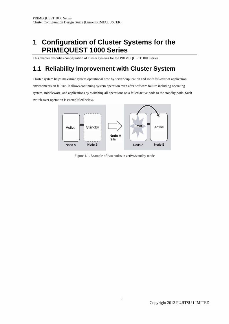
1.1 Reliability Improvement with Cluster System Cluster system helps maximize system operational time by server duplication and swift fail-over of application
environments on failure. It allows continuing system operation even after software failure including operating
system, middleware, and applications by switching all operations on a failed active node to the standby node. Such
switch-over operation is exemplified below.
Figure 1.1. Example of two nodes in active/standby mode
Copyright 2012 FUJITSU LIMITED
5
PRIMEQUEST 1000 Series Cluster Configuration Design Guide (Linux/PRIMECLUSTER)
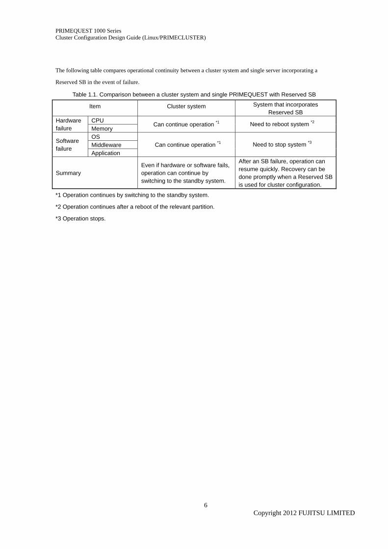
The following table compares operational continuity between a cluster system and single server incorporating a
Reserved SB in the event of failure.
Table 1.1. Comparison between a cluster system and single PRIMEQUEST with Reserved SB
Item Cluster system System that incorporates Reserved SB
CPU Hardware failure Memory
Can continue operation *1 Need to reboot system *2
OS Middleware
Software failure
Application Can continue operation *1 Need to stop system *3
Summary Even if hardware or software fails, operation can continue by switching to the standby system.
After an SB failure, operation can resume quickly. Recovery can be done promptly when a Reserved SB is used for cluster configuration.
*1 Operation continues by switching to the standby system.
*2 Operation continues after a reboot of the relevant partition.
*3 Operation stops.
Copyright 2012 FUJITSU LIMITED
6
PRIMEQUEST 1000 Series Cluster Configuration Design Guide (Linux/PRIMECLUSTER)
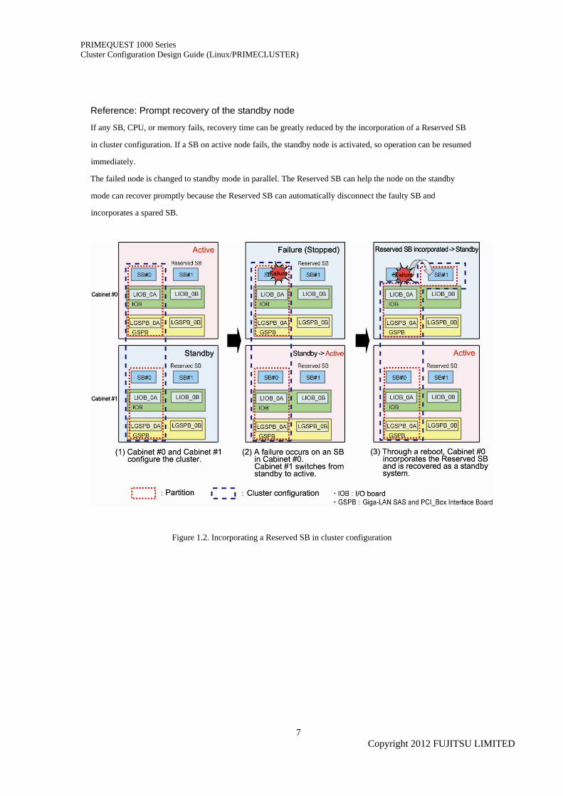
Reference: Prompt recovery of the standby node
If any SB, CPU, or memory fails, recovery time can be greatly reduced by the incorporation of a Reserved SB
in cluster configuration. If a SB on active node fails, the standby node is activated, so operation can be resumed
immediately.
The failed node is changed to standby mode in parallel. The Reserved SB can help the node on the standby
mode can recover promptly because the Reserved SB can automatically disconnect the faulty SB and
incorporates a spared SB.
Figure 1.2. Incorporating a Reserved SB in cluster configuration
Copyright 2012 FUJITSU LIMITED
7
PRIMEQUEST 1000 Series Cluster Configuration Design Guide (Linux/PRIMECLUSTER)
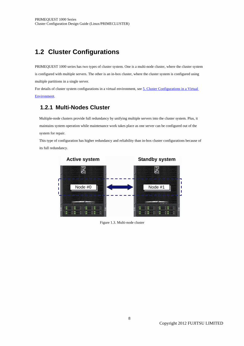
1.2 Cluster Configurations
PRIMEQUEST 1000 series has two types of cluster system. One is a multi-node cluster, where the cluster system
is configured with multiple servers. The other is an in-box cluster, where the cluster system is configured using
multiple partitions in a single server.
For details of cluster system configurations in a virtual environment, see 5. Cluster Configurations in a Virtual
Environment.
1.2.1 Multi-Nodes Cluster
Multiple-node clusters provide full redundancy by unifying multiple servers into the cluster system. Plus, it
maintains system operation while maintenance work takes place as one server can be configured out of the
system for repair.
This type of configuration has higher redundancy and reliability than in-box cluster configurations because of
its full redundancy.
Active system Standby system
Figure 1.3. Multi-node cluster
Node #0 Node #1
Copyright 2012 FUJITSU LIMITED
8
PRIMEQUEST 1000 Series Cluster Configuration Design Guide (Linux/PRIMECLUSTER)
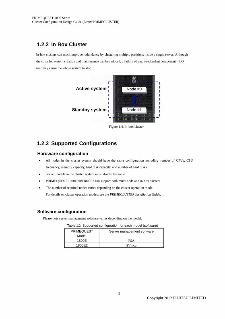
1.2.2 In Box Cluster
In-box clusters can much improve redundancy by clustering multiple partitions inside a single server. Although
the costs for system creation and maintenance can be reduced, a failure of a non-redundant component – I/O
unit may cause the whole system to stop.
Active system Node #0
Standby system Node #1
Figure 1.4. In-box cluster
1.2.3 Supported Configurations
Hardware configuration • All nodes in the cluster system should have the same configuration including number of CPUs, CPU
frequency, memory capacity, hard disk capacity, and number of hard disks
• Server models in the cluster system must also be the same
• PRIMEQUEST 1800E and 1800E2 can support both multi-node and in-box clusters
• The number of required nodes varies depending on the cluster operation mode.
For details on cluster operation modes, see the PRIMECLUSTER Installation Guide.
Software configuration Please note server management software varies depending on the model.
Table 1.2. Supported configuration for each model (software)
PRIMEQUEST Model
Server management software
1800E PSA 1800E2 SVmco
Copyright 2012 FUJITSU LIMITED
9
PRIMEQUEST 1000 Series Cluster Configuration Design Guide (Linux/PRIMECLUSTER)
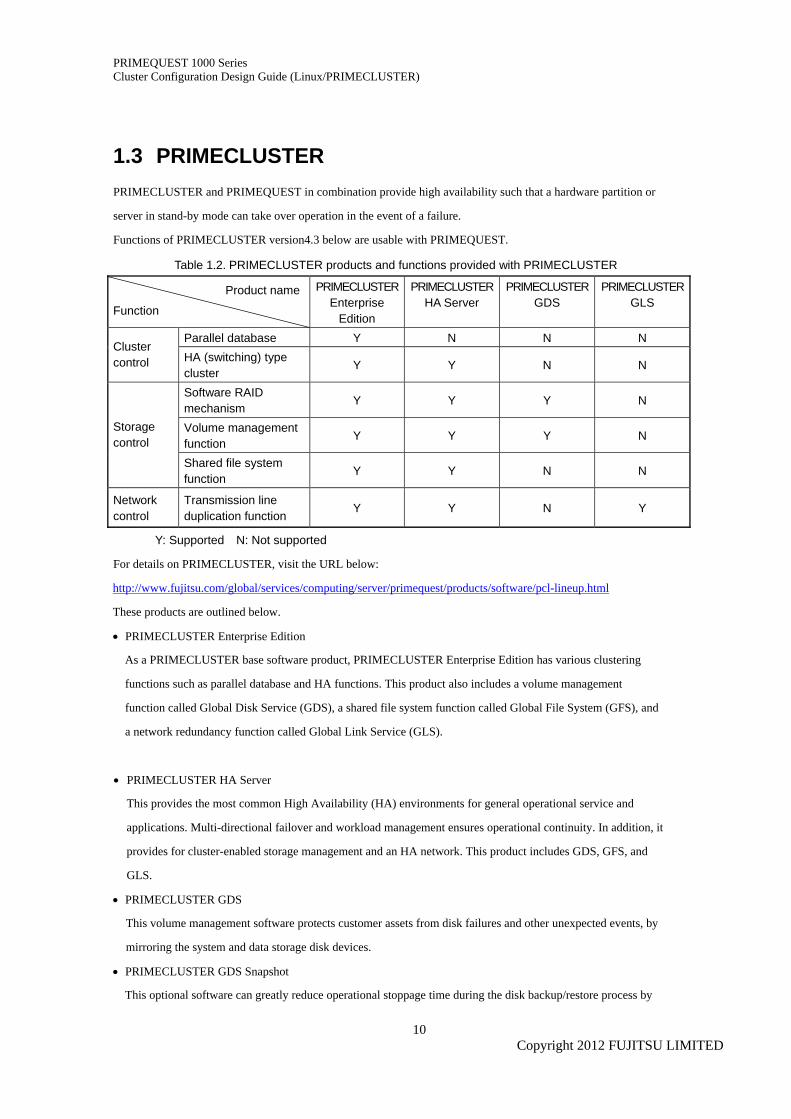
1.3 PRIMECLUSTER PRIMECLUSTER and PRIMEQUEST in combination provide high availability such that a hardware partition or
server in stand-by mode can take over operation in the event of a failure.
Functions of PRIMECLUSTER version4.3 below are usable with PRIMEQUEST.
Table 1.2. PRIMECLUSTER products and functions provided with PRIMECLUSTER
Product name
Function
PRIMECLUSTEREnterprise
Edition
PRIMECLUSTERHA Server
PRIMECLUSTER GDS
PRIMECLUSTERGLS
Parallel database Y N N N Cluster control HA (switching) type
cluster Y Y N N
Software RAID mechanism
Y Y Y N
Volume management function
Y Y Y N Storage control
Shared file system function
Y Y N N
Network control
Transmission line duplication function
Y Y N Y
Y: Supported N: Not supported
For details on PRIMECLUSTER, visit the URL below:
http://www.fujitsu.com/global/services/computing/server/primequest/products/software/pcl-lineup.html
These products are outlined below.
• PRIMECLUSTER Enterprise Edition
As a PRIMECLUSTER base software product, PRIMECLUSTER Enterprise Edition has various clustering
functions such as parallel database and HA functions. This product also includes a volume management
function called Global Disk Service (GDS), a shared file system function called Global File System (GFS), and
a network redundancy function called Global Link Service (GLS).
• PRIMECLUSTER HA Server
This provides the most common High Availability (HA) environments for general operational service and
applications. Multi-directional failover and workload management ensures operational continuity. In addition, it
provides for cluster-enabled storage management and an HA network. This product includes GDS, GFS, and
GLS.
• PRIMECLUSTER GDS
This volume management software protects customer assets from disk failures and other unexpected events, by
mirroring the system and data storage disk devices.
• PRIMECLUSTER GDS Snapshot
This optional software can greatly reduce operational stoppage time during the disk backup/restore process by
Copyright 2012 FUJITSU LIMITED
10

PRIMEQUEST 1000 Series Cluster Configuration Design Guide (Linux/PRIMECLUSTER)
instantly creating a snapshot of a disk or volume.
• PRIMECLUSTER GLS
This software product offers network redundancy by multiplex NICs (network interface cards). GLS is the
optimal for a system with high network continuity.
Copyright 2012 FUJITSU LIMITED
11
PRIMEQUEST 1000 Series Cluster Configuration Design Guide (Linux/PRIMECLUSTER)
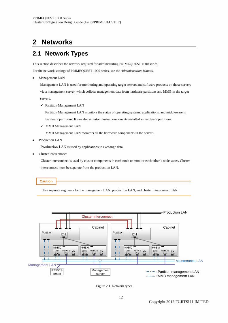
2 Networks 2.1 Network Types This section describes the network required for administrating PRIMEQUEST 1000 series.
For the network settings of PRIMEQUEST 1000 series, see the Administration Manual.
• Management LAN
Management LAN is used for monitoring and operating target servers and software products on those servers
via a management server, which collects management data from hardware partitions and MMB in the target
servers.
Partition Management LAN
Partition Management LAN monitors the status of operating systems, applications, and middleware in
hardware partitions. It can also monitor cluster components installed in hardware partitions.
MMB Management LAN
MMB Management LAN monitors all the hardware components in the server.
• Production LAN
Production LAN is used by applications to exchange data.
• Cluster interconnect
Cluster interconnect is used by cluster components in each node to monitor each other’s node states. Cluster
interconnect must be separate from the production LAN.
Caution
Use separate segments for the management LAN, production LAN, and cluster interconnect LAN.
Production LAN Cluster interconnect
Cabinet Cabinet
Maintenance LANManagement LAN
REMCS center
Managementserver Partition management LAN
MMB management LAN
Figure 2.1. Network types
Copyright 2012 FUJITSU LIMITED
12
PRIMEQUEST 1000 Series Cluster Configuration Design Guide (Linux/PRIMECLUSTER)
2.2 Cluster Operations of Management LAN and Partition Management LAN
Management LAN is used for monitoring and operating the cluster system by inter-working with PRIMEQUEST
hardware and PRIMECLUSTER.
Node state monitoring
If a system panics or is powered off, or if other problem occurs without warning, this function can help detect
such problems immediately.
Forcible shutdown
This function can prevent user resource contention by intentionally triggering a panic in a problematic node
and resetting it.
The Partition Management LAN is connected to a console with Web Based Admin View, which is used for
operational management for the cluster system. For details on Web-Based Admin View, visit the URL below,
using search string "PRIMECLUSTER," and view the PRIMECLUSTER Web-Based Admin View Operation
Guide for PRIMECLUSTER 4.3A00 or later.
http://www.fujitsu.com/global/services/computing/server/primequest/documents/pcl-manuals.html
2.3 Cluster Interconnect PRIMECLUSTER can recover operations of failed nodes swiftly by finding the problem and transferring all
information required for fail-over. Cluster interconnect is used to monitor the status of all nodes to find problems
at the earliest possible moment and for transfer of information for fail-over.
2.3.1 Network Equipment
Cluster interconnect configuration example
Fujitsu recommends cluster interconnect paths be fully redundant. In other words, any failure in one
interconnect path must not affect any other interconnect path. Otherwise, component failure can make all
interconnects inaccessible. For instance, two PCI slots linked to a common PCI Express switch will become
unusable if the PCI Express switch fails.
For full redundancy I/O components linked to PCI slots should be fully separated from each other. Fujitsu
recommends one interconnect be drawn from GSPB and another drawn from NIC mounted in the PCI slots
below:
• IOB PCI slot, or
• PCI_Box PCI slot
All nodes remain connected even if any I/O component such as a GSPB, IOB, or PCI_Box fails.
Copyright 2012 FUJITSU LIMITED
13
PRIMEQUEST 1000 Series Cluster Configuration Design Guide (Linux/PRIMECLUSTER)
2.3.2 Cluster Interconnect Configuration
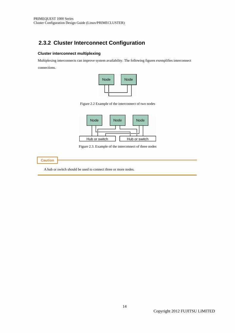
Cluster interconnect multiplexing
Multiplexing interconnects can improve system availability. The following figures exemplifies interconnect
connections.
Figure 2.2 Example of the interconnect of two nodes
Node Node
Node Node Node
Hub or switch Hub or switch
Figure 2.3. Example of the interconnect of three nodes
Caution
A hub or switch should be used to connect three or more nodes.
Copyright 2012 FUJITSU LIMITED
14
PRIMEQUEST 1000 Series Cluster Configuration Design Guide (Linux/PRIMECLUSTER)
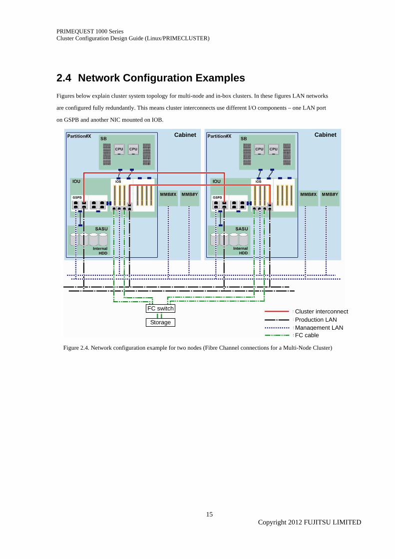
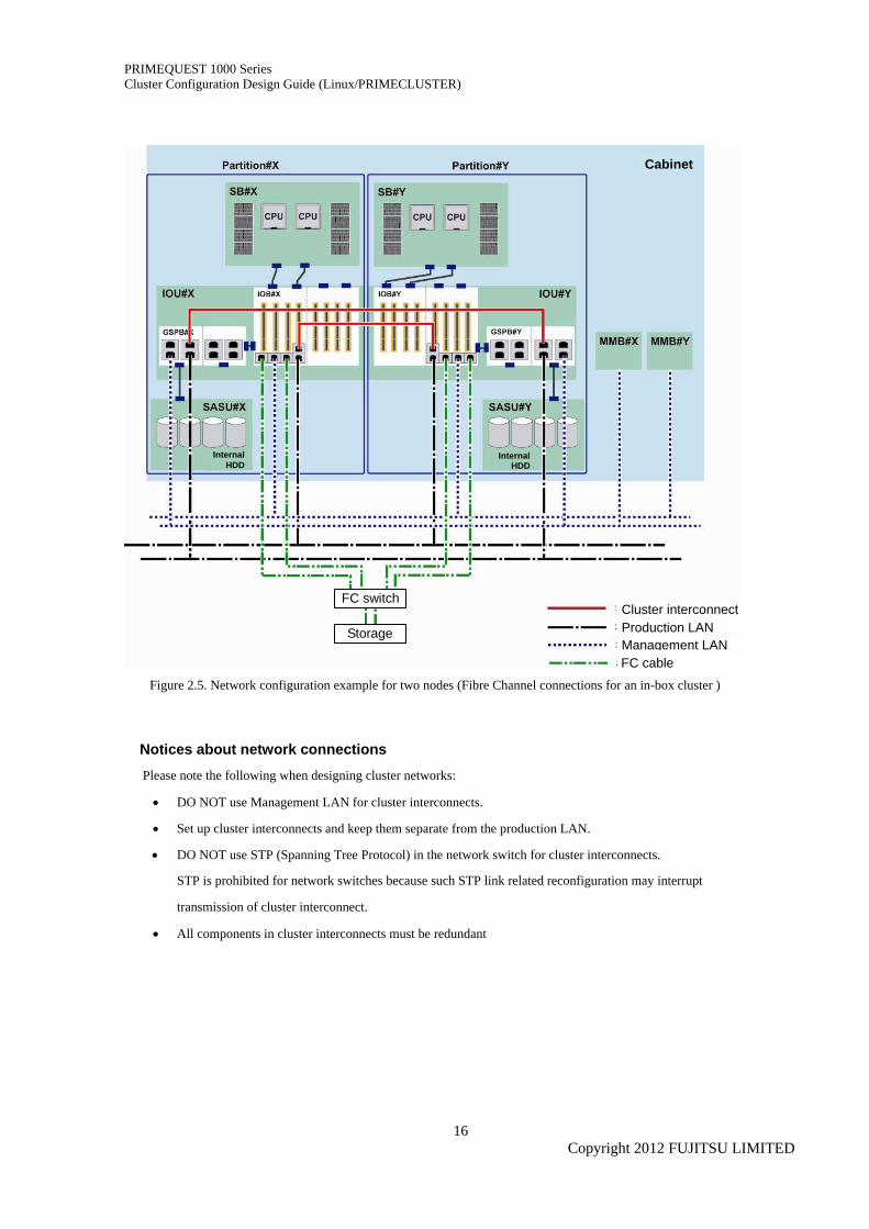
2.4 Network Configuration Examples Figures below explain cluster system topology for multi-node and in-box clusters. In these figures LAN networks
are configured fully redundantly. This means cluster interconnects use different I/O components – one LAN port
on GSPB and another NIC mounted on IOB.
Cabinet Cabinet
FC switch
Storage
Internal HDD
Internal HDD
Cluster interconnectProduction LANManagement LANFC cable
Figure 2.4. Network configuration example for two nodes (Fibre Channel connections for a Multi-Node Cluster)
Copyright 2012 FUJITSU LIMITED
15
PRIMEQUEST 1000 Series Cluster Configuration Design Guide (Linux/PRIMECLUSTER)
Cabinet
FC switch
Internal HDD
Internal HDD
Cluster interconnectProduction LAN Management LANFC cable
Storage
Figure 2.5. Network configuration example for two nodes (Fibre Channel connections for an in-box cluster )
Notices about network connections
Please note the following when designing cluster networks:
• DO NOT use Management LAN for cluster interconnects.
• Set up cluster interconnects and keep them separate from the production LAN.
• DO NOT use STP (Spanning Tree Protocol) in the network switch for cluster interconnects.
STP is prohibited for network switches because such STP link related reconfiguration may interrupt
transmission of cluster interconnect.
• All components in cluster interconnects must be redundant
Copyright 2012 FUJITSU LIMITED
16
PRIMEQUEST 1000 Series Cluster Configuration Design Guide (Linux/PRIMECLUSTER)
3 Shared I/O Unit 3.1 External Storage System Fibre Channel and iSCSI are usable for connection to external storage system:
Notices
• Duplication of connections with external storage system
Fujitsu recommends duplicating PCI cards for external storage system connection.
Fujitsu also recommends that each duplicated PCI card is mounted in a PCI slot so that any single I/O component
failure (PCIe switch, chips or wires) does not make all duplicated PCI cards inaccessible. Always ensure I/O
components related to PCI slots are fully separated.
• RAID level
DO NOT use RAID0 for external storage system. For details of RAID levels, refer to the documents for
each respective storage system.
• Recommendations for redundant controllers and paths
Fujitsu recommends that each storage system consists of dual controllers and redundant paths.
• To avoid performance degradation, due to access conflicts on shared storage system, take the following
measures:
Do not use too many storage systems to reduce performance overheads
Deploy different databases or files to different disks for improved parallelism
DO NOT allot too many disk drives to one interface to avoid overloading the disk interface
3.2 Tape Device Fibre Channel is usable for sharing an LTO library unit between multiple nodes.
Caution
Backup software is required when using a tape device or library unit. For details on backup software, see 4. Backup/Restore.
Copyright 2012 FUJITSU LIMITED
17
PRIMEQUEST 1000 Series Cluster Configuration Design Guide (Linux/PRIMECLUSTER)
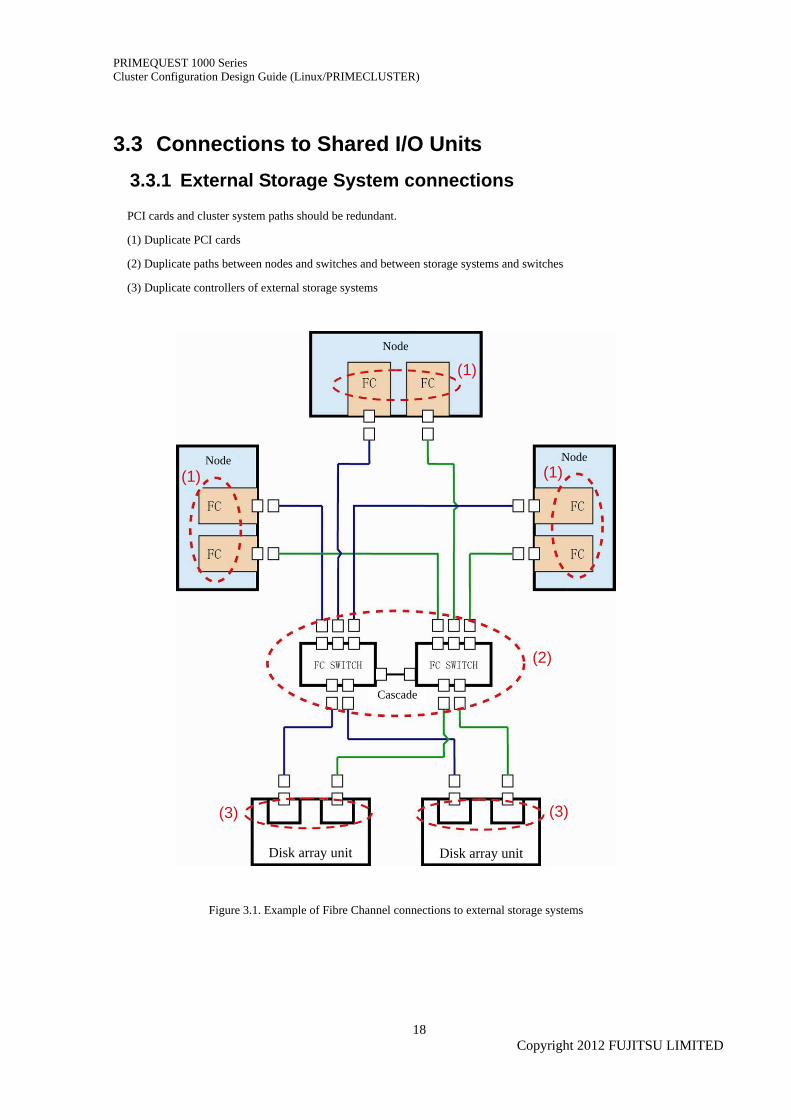
3.3 Connections to Shared I/O Units 3.3.1 External Storage System connections
PCI cards and cluster system paths should be redundant.
(1) Duplicate PCI cards
(2) Duplicate paths between nodes and switches and between storage systems and switches
(3) Duplicate controllers of external storage systems
Node
Node Node
Cascade
Disk array unit
(1) (1)
(1)
(2)
(3) (3)
Disk array unit
Figure 3.1. Example of Fibre Channel connections to external storage systems
Copyright 2012 FUJITSU LIMITED
18

PRIMEQUEST 1000 Series Cluster Configuration Design Guide (Linux/PRIMECLUSTER)
Notices
Please note the following regarding external storage systems in cluster system configuration.
• For external storage system connection limits and available protocols , see the relevant documents.
• If the ports of all switches are insufficient to keep server-storage connections redundant, use cascade
connections. For details of relevant switch specifications, see documents for the relevant switches.
• Fujitsu recommends using ETERNUS multipath driver (MPD) for ETERNUS connections.
PRIMECLIUSTER can support MPD paths in a range of two to eight.
• Notes on immediate cluster switching on I/O unit failure
It may take time to complete the fail-over operation if an I/O unit containing a failed system disk. If an
ETERNUS or Fibre Channel fails and ext3 file system is used with the default setting, PRIMECLUSTER
tries as long as possible to continue system operation. Since system operation is based on information
kept in memory, the system may not immediately switch to standby mode.
To switch clusters immediately on failure of an I/O unit containing system volumes, set the parameters
below.
Specify "errors=panic" for the mount option of ext3 on each partition contained in the system
volume. As a result, as soon as the ext3 file system is notified of the I/O error caused by the I/O
unit failure, it will trigger an operating system panic and switch clusters.
However, a certain amount of time may still be needed to notify the ext3 file system of the I/O
error. Note that clusters are not switched immediately in that case. (Periodic writing to system
volumes helps detect I/O errors early time.)
Example of /etc/fstab specification:
( directories such as “/”, “/var”, and “/home” are contained in one system volume)
LABEL=/ / ext3 errors=panic 1 1
LABEL=/boot /boot ext3 errors=panic 1 2
LABEL=/var /var ext3 errors=panic 1 3
LABEL=/home /home ext3 errors=panic 1 4
Copyright 2012 FUJITSU LIMITED
19
PRIMEQUEST 1000 Series Cluster Configuration Design Guide (Linux/PRIMECLUSTER)
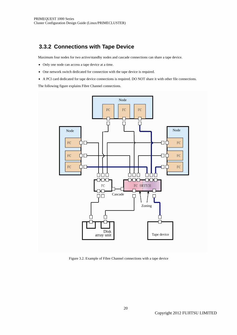
3.3.2 Connections with Tape Device
Maximum four nodes for two active/standby nodes and cascade connections can share a tape device.
• Only one node can access a tape device at a time.
• One network switch dedicated for connection with the tape device is required.
• A PCI card dedicated for tape device connections is required. DO NOT share it with other file connections.
The following figure explains Fibre Channel connections.
Node
Node Node
Cascade
Disk array unit
Zoning
Tape device
Figure 3.2. Example of Fibre Channel connections with a tape device
Copyright 2012 FUJITSU LIMITED
20
PRIMEQUEST 1000 Series Cluster Configuration Design Guide (Linux/PRIMECLUSTER)
4 Backup/Restoration 4.1 System Volume Backup/Restoration In a local boot configuration, PRIMECLUSTER GDS and PRIMECLUSTER GDS Snapshot help you back up
system volumes at any time during system operation. For details of PRIMECLUSTER GDS and
PRIMECLUSTER GDS Snapshot, see PRIMECLUSTER Global Disk Services Description. Also, be sure to create
backup data before installation, upgrade, or removal of software products, and before modification of software or
hardware settings.
If interruption of a node is allowed for backup, you can store such backup data on an external storage system.
However, you need to notice the node stoppage and follow a predetermined operational procedure for the clustered
system. Also for restoration of backup data, follow the general restoration procedure.
Backup data must be created each time you modified the cluster configuration. If data taken before such a
modification is mistakenly restored, an error occurs during the restoration process.
The cluster also stores information specific to each node. This means nodes may store different information. Make
sure that backup and restoration operations are executed for all nodes.
For the details of cluster system setup, see the relevant PRIMECLUSTER manuals.
Caution
• Note only Red Hat Enterprise Linux 6 for Intel 64 can be used with PRIMECLUSTER GDS or PRIMECLUSTER GDS Snapshot for backup purposes.
• To save backup data collected from a guest operating system to tape or other external storage media, transfer the backup data to hypervisor, and then save the data from hypervisor to the external storage device.
Copyright 2012 FUJITSU LIMITED
21
PRIMEQUEST 1000 Series Cluster Configuration Design Guide (Linux/PRIMECLUSTER)
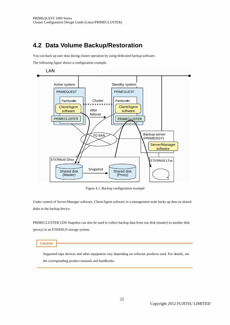
4.2 Data Volume Backup/Restoration You can back up user data during cluster operation by using dedicated backup software.
The following figure shows a configuration example.
Cluster
Standby system
After failover
Client/Agent software
Active system
Snapshot
Client/Agent software
Shared disk (Master)
Backup server (PRIMERGY)
Shared disk(Proxy)
Server/Manager software
Figure 4.1. Backup configuration example
Under control of Server/Manager software, Client/Agent software in a management node backs up data on shared
disks to the backup device.
PRIMECLUSTER GDS Snapshot can also be used to collect backup data from one disk (master) to another disk
(proxy) in an ETERNUS storage system.
Caution
Supported tape devices and other equipment vary depending on software products used. For details, see
the corresponding product manuals and handbooks.
Copyright 2012 FUJITSU LIMITED
22

PRIMEQUEST 1000 Series Cluster Configuration Design Guide (Linux/PRIMECLUSTER)
The software products listed below (or a network storage server) can be used for such purposes. The products
below can help backup operations continue painlessly even after a failover occurs:
• PRIMECLUSTER GDS Snapshot
• ETERNUS SF AdvancedCopy Manager
Remarks
In a cluster where ETERNUS SF Advanced Copy Manager is installed on the production server and other backup software is installed on the backup server, ETERNUS SF Advanced Copy Manager creates replicas (copied data), which can be backed up directly from the backup server. Therefore, no special attention needs to be paid to the cluster.
Copyright 2012 FUJITSU LIMITED
23
PRIMEQUEST 1000 Series Cluster Configuration Design Guide (Linux/PRIMECLUSTER)
5 Cluster Configurations in Virtual Environments 5.1 Types of Cluster Configurations Using Virtual
Machine Functions Using PRIMECLUSTER, virtualized servers can be clustered in the same way physical servers..
PRIMECLUSTER supports the following virtual environments:
• KVM for Red Hat Enterprise Linux 6
• VMware
Cluster configurations for virtual environments are as follows:
• Configuration with one Management Operating System (See 5.1.1 Configuration with one management
operating system.)
• Inbox cluster configuration with multiple Management Operating Systems (See 5.1.2 Configuration with
multiple management operating systems.)
• Multi-node Cluster configuration (See 5.1.2 Configuration with multiple management operating systems.)
For details and notes on cluster systems using the virtual machine function, see the PRIMECLUSTER Installation
Guide.
Remarks
• For the KVM environment, translate "management operating system" as "hypervisor."
• For the VMware environment, translate "management operating system" as "ESX host."
Notices
In a virtual environment, multiple cluster systems can share a physical NIC. (Virtual bridges need to be created
separately.)
Copyright 2012 FUJITSU LIMITED
24
PRIMEQUEST 1000 Series Cluster Configuration Design Guide (Linux/PRIMECLUSTER)
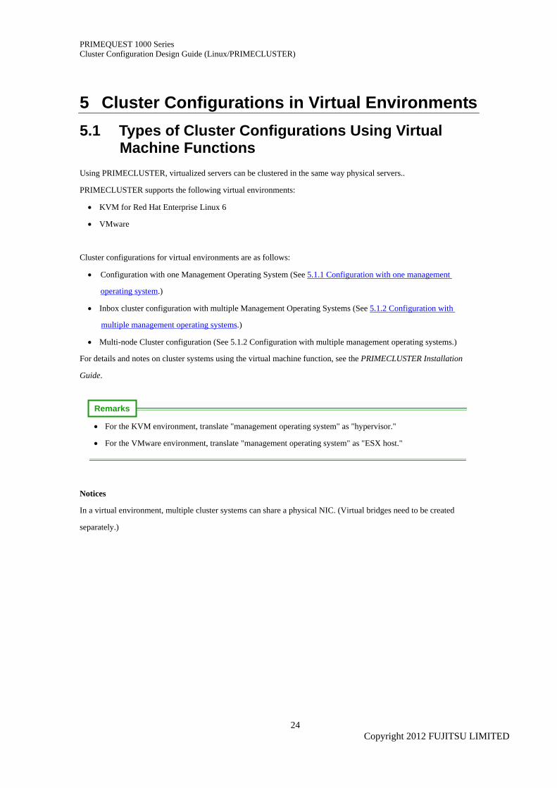
5.1.1 Configuration with One Management Operating System
Fujitsu recommends this configuration is only used for test environments.
One physical server serves as the cluster system where applications can continue operation in the event of a
failure in a Guest Operating System.
Caution
• This configuration cannot be used in VMware environments.
• The configuration requires virtual network entity definitions for inter-connecting Guest Operating
Systems ( note it is designed for test environment use.)
Figure 5.1. Example of a configuration with one Management Operating System
Copyright 2012 FUJITSU LIMITED
25
PRIMEQUEST 1000 Series Cluster Configuration Design Guide (Linux/PRIMECLUSTER)
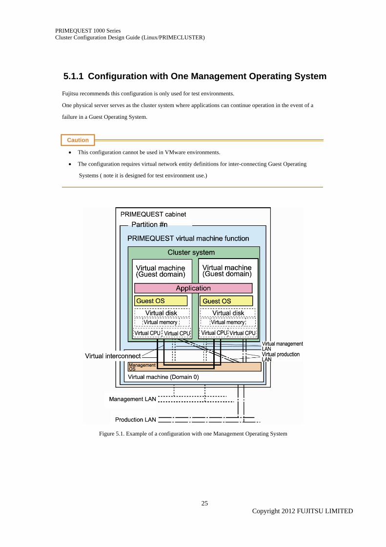
5.1.2 Configuration with Multiple Management Operating Systems
In this configuration applications can continue operation even if a hardware (network or disk) failure occurs.
• In-box Cluster
Figure 5.2. Example of a configuration with two Management Operating Systems (in-box cluster)
Copyright 2012 FUJITSU LIMITED
26
PRIMEQUEST 1000 Series Cluster Configuration Design Guide (Linux/PRIMECLUSTER)
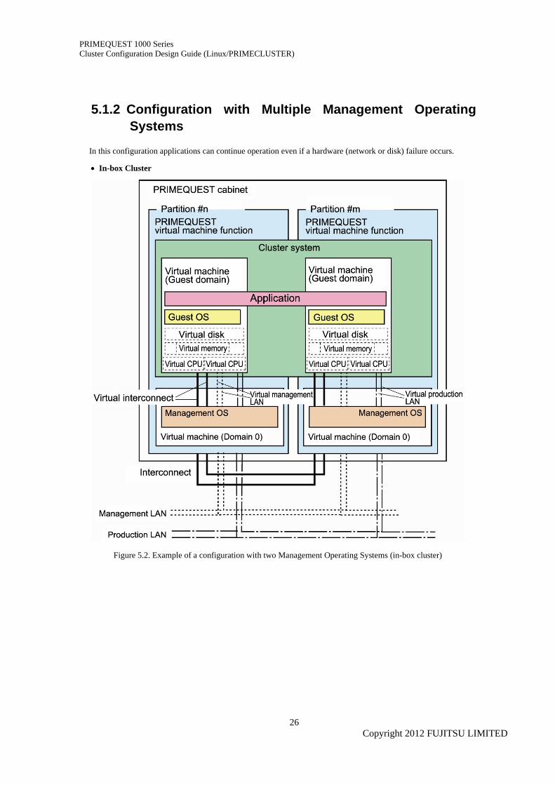
• Multi-nodes Cluster
Figure 5.3. Example of a configuration with two Management Operating Systems by multi-node cluster
Copyright 2012 FUJITSU LIMITED
27
PRIMEQUEST 1000 Series Cluster Configuration Design Guide (Linux/PRIMECLUSTER)
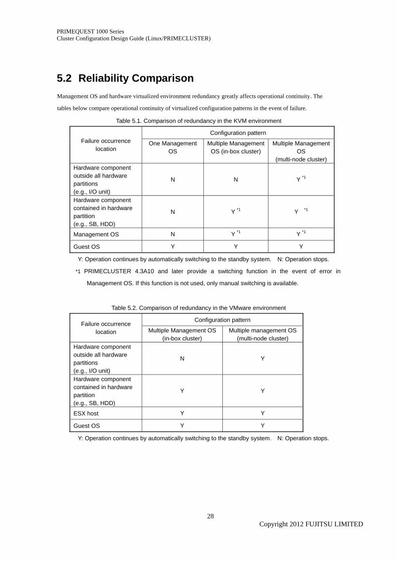
5.2 Reliability Comparison Management OS and hardware virtualized environment redundancy greatly affects operational continuity. The
tables below compare operational continuity of virtualized configuration patterns in the event of failure.
Table 5.1. Comparison of redundancy in the KVM environment
Configuration pattern Failure occurrence
location One Management
OS Multiple Management
OS (in-box cluster) Multiple Management
OS (multi-node cluster)
Hardware component outside all hardware partitions (e.g., I/O unit)
N N Y *1
Hardware component contained in hardware partition (e.g., SB, HDD)
N Y *1 Y *1
Management OS N Y *1 Y *1
Guest OS Y Y Y
Y: Operation continues by automatically switching to the standby system. N: Operation stops.
*1 PRIMECLUSTER 4.3A10 and later provide a switching function in the event of error in
Management OS. If this function is not used, only manual switching is available.
Table 5.2. Comparison of redundancy in the VMware environment
Configuration pattern Failure occurrence
location Multiple Management OS (in-box cluster)
Multiple management OS (multi-node cluster)
Hardware component outside all hardware partitions (e.g., I/O unit)
N Y
Hardware component contained in hardware partition (e.g., SB, HDD)
Y Y
ESX host Y Y
Guest OS Y Y
Y: Operation continues by automatically switching to the standby system. N: Operation stops.
Copyright 2012 FUJITSU LIMITED
28
PRIMEQUEST 1000 Series Cluster Configuration Design Guide (Linux/PRIMECLUSTER)
6 Note 6.1 Notes on PRIMEQUEST 1000 Series
For in-box cluster configurations of PRIMEQUEST 1800E and 1800E2, Fujitsu recommends that
components such as IOB and GSPB are not shared between hardware partitions. Such separation of
IOB and GSPB greatly improves operational continuity of the clustered system.
PSA or SVmco must be installed in each hardware partition.
• PSA or SVmco is required for operation of PRIMEQUEST in all cluster system nodes.
Cluster switching fails if PSA or SVmco is not installed properly.
• PSA is available with PRIMEQUEST 1800E, SVmco for PRIMEQUEST 1800E2
With single MMB, every MMB failure triggers fail-over. However, the fail-over is suspended and the
entire system remains interrupted until administrator operates fail-over. So, replacement of faulty a
MMB is necessary for immediate and automatic fail-over.
When configuring a cluster, be sure to set the parameters below.
• Physical IP address settings of MMB (MMB#0 and MMB#1)
See the following document: 3.3.6 Configuring the MMB Network in the Installation Manual
• IP address setting of Management LAN
See the following documents according to the model used.
PRIMEQUEST 1800E: 6.2.7 Setting Management LAN IP address in the Installation Manual
PRIMEQUEST 1800E2: SVmco User Manual
• Firewall function settings
See the following documents according to the model used.
PRIMEQUEST 1800E: 6.2.4 Checking the firewall function (opening ports) in the Installation Manual
PRIMEQUEST 1800E2: SVmco User Manual
Copyright 2012 FUJITSU LIMITED
29

PRIMEQUEST 1000 Series Cluster Configuration Design Guide (Linux/PRIMECLUSTER)
6.2 Notes on PRIMECLUSTER PRIMEQUEST 1000 series supports PRIMECLUSTER 4.3A00 and later.
For PRIMECLUSTER with Oracle Database, see the following manual for investigating availability of
operating systems and Oracle Database:
PRIMECLUSTER Wizard for Oracle Configuration and Administration Guide
When configuring cluster, set slew mode for NTP to synchronize NTP time.
In the cluster system environment, Fujitsu recommends connecting two UPS units to each server and
each external storage equipment.
If UPS is not properly connected to equipments above, failover of clusters may not work properly in the
event of power shortage or power supply failure.
Physical cluster configurations inter-working with hardware mechanisms can detect node error
immediately. However a virtual environment without such inter-working with hardware cannot enjoy
such immediate error detection on Guest Operating System.
Copyright 2012 FUJITSU LIMITED
30
PRIMEQUEST 1000 Series Cluster Configuration Design Guide (Linux/PRIMECLUSTER)
Appendix
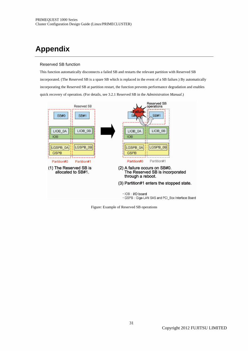
Reserved SB function
This function automatically disconnects a failed SB and restarts the relevant partition with Reserved SB
incorporated. (The Reserved SB is a spare SB which is replaced in the event of a SB failure.) By automatically
incorporating the Reserved SB at partition restart, the function prevents performance degradation and enables
quick recovery of operation. (For details, see 3.2.1 Reserved SB in the Administration Manual.)
Figure: Example of Reserved SB operations
Copyright 2012 FUJITSU LIMITED
31
PRIMEQUEST 1000 Series Cluster Configuration Design Guide (Linux/PRIMECLUSTER)
Revision History
Edition Date Revised location (*1) Description
01 2010-03-31 - -
02 2010-08-10 5 Cluster Configurations in a Virtual Environment
Addition of a chapter
03 2011-04-28 All pages Support of new models
04 2011-06-30 All pages Support of RHEL6 and VMware
(*1) Chapter, section, and item numbers in the "Revised location" column refer to those in the latest edition of
the document.
Copyright 2012 FUJITSU LIMITED
32

PRIMEQUEST 1000 Series Cluster Configuration Design Guide (Linux/PRIMECLUSTER)
Terms of Use
Copyrights, trademark rights, and other intellectual property rights
The content (including text, images, and audio) is protected by copyrights, trademark rights, and other
intellectual property rights. The content can be printed or downloaded for personal use only. Fujitsu or the
rights holder reserves the right to approve or withhold permission for use for any other purpose (e.g., for reuse
on your own webpage or upload to another server).
Limitations of warranty
Fujitsu provides no guarantee of the accuracy, merchantability, or fitness for use of the content. Fujitsu assumes
no legal responsibility for any damage arising from use of the content. The content in this manual may be
revised or deleted without prior notice.
For clarification of any unclear points, send us your comments or inquiries by e-mail to
All rights reserved.
C122-A007-04EN
June 2011
Copyright 2012 FUJITSU LIMITED
33