principles of fastener pretreatment - infohouseinfohouse.p2ric.org/ref/28/27992.pdf · principles...
TRANSCRIPT

- ‘REATMENT
HEW76 Principles of Fastener Pretreatment 277VL
by Roger Kelly Man-Gill Chemical Co., Cleveland, OH
asteners are used throughout F industry to join all types of parts. Even the smallest appliances such as a gas grill or fertilizer spreader may use 20 or 30 fasteners. Major appliances may use a hundred or more fasteners, and a typical automobile may employ 1500 to 3000 fasteners. The fhishes used on these fasteners
can be strictly decorative, or may be primarily functional to provide COITO- sion resistance. In many cases, the finish is intended to be both functional and also provide a certain appearance characteristic. Organic coatings (paints) can provide both superior cor- rosion resistance and the ability to color coordinate the fastener with its sur- roundings.
This article is intended as a primer for both those using fasteners and specifying the finish for them, as well as those who are planning to apply those finishes. The article serves also to provide a better understanding of the principles of pretreating those fasteners in preparation for organic coatings. The
. emphasis will be on the zinc phosphat- ing process and its purpose, rather than the subsequent organic coating proc- esses.
WHY ZINC PHOSPHATE? Heavy zinc phosphate coatings are
employed as the pretreatment of choice for fasteners because the crystalline structure provides both an insulation against the electrochemical corrosion reaction and also a roughened surface to provide a “mechanical tooth” for the adhesion of subsequent organic coat- ings. The microscopic voids between the crystals act as a sponge to absorb and trap oils and paints between them.
Zinc phosphate coatings are the most consistent and economical method of developing this desired surface. Phos- . phate coating weights remain consis- tently above 1500 mg/ft2 in both high
volume and low volume operations. Because of the volume of fasteners
to be processed, the most common method of processing is in a slowly rotating barrel of perforated steel. Zinc phosphate solution transfers through the perforations in the barrel and the open spaces between the parts in the barrel to develop a uniform, dense coat- ing,
THEPROCESS The zinc phosphate process includes
four basic sequences: cleaning, pickl- ing, phosphating and rinsing. We will investigate each of these processes and its importance separately. It is impor- tant, however, ta start with a basic knowledge of the complete process cycle. Table I describes the steps of the treatment cycle, its times and tempera- tures.
The actual sequence may vary with specific applications. For example, some systems may not require a pickle if there is no heat treat scale to remove, or if there are no rusted parts to be phosphated. Some systems do not em- ploy a rinse between the first and sec- ond cleaner stages, if space considera- tions have forced elimination of a stage, or if an older system has been con- verted.
CLEANING The obvious purpose of the alkaline
cleaning process is the removal of oils, soils and forming lubricants. In the zinc phosphate process, however, cleaning is possibly the single most important part of the process.
The cleaners are typically highly al- kaline, with a variety of surfactants de- pending upon the design of the cleaner. Cleaners are designed either to emul- sify the soils removed from the parts or float the soils. Earlier cleaners primarily emulsified the soils absorbing up to 2 to 5% of their volume as oil. Unfortunately, even the best eventually became saturated with soils, which ul- timately split out of emulsion, rede- positing on the work, preventing sub- sequent pickling and phosphating.
Emulsifying cleaners must be de- signed to be extremely well rinsing to remove the soils in the cleaner film dragged out on the parts. Ideally they also re-emulsify very easily in the subsequent rinse stage to aid removal of the soil loaded cleaner from the parts. Figure 1 illustrates the general mechanism of an emulsifying cleaner that easily re-emulsifies in the rinse for complete removal from the parts.
Today’s cleaners and cleaning tanks are more and more designed to rapidly
*
Table 1. A Typical Heavy Zinc Phosphate Cycle
Barrel Rotation Time Temperature
Stage (rpm) (minutes) j“F)
Alkaline clean 5-7 10-1 5 180-21 0
Alkaline clean (or descale) 5-7 10-1 5 180-21 0
Pickle* 5-7 5-1 5 1 10-1 60
Water rinse 5-7 1-2 Ambient
Water rinse 5-7 1-2 Ambient
Water rinse 5-7 1-2 Ambient
Water rinse lY2 to 2% 1-2 Ambient Zinc phosphate 1 ’/2 to 2% 10-20 165-1 80
Final seal 11/2 to 2% 1-2 170-200 Dry (optional) 250-350
*Pickle temperatures vary depending upon the acid selected.

’ ? .
I J I I I I
CLEANER RINSE
Alkali I Rinse
Drag Out .Oils and Soils Oils Soils Cleaner Film Float Off in
Fig. 1. General mechanism on the operation of an emulsifying cleaner. -
separate the removed soils and to float and remove them from the cleaner tank. The major advantages of a properly de- signed and operated cleaner system to separate the removed oils are:
1. Longer solution life through re- moval of oils from the system.
2. Easier automatic control since these solutions respond to conductivity better than emulsions.
3. More consistent cleaning becausc: the cleaning fraction remains cleaner.
4. Lower waste treatment costs since the oil is disposed of separately and there are fewer bath dumps.
The success of floating oil type cleaners depends upon rapid separation of oil within the system and rapid re- moval of the separated oil from the sys- tem. The removal is generally accom- plished in a separate side arm tank and skimming overflow on the cleaner tank, with a mechanical oil skimmer.
Figure 2 demonstrates the typical overflowing oil skimmer tank design, as well as a typical separate oil skimmer tank. Figure 3 is a close-up of the actual oil skimmer device.
Cleaning problems vary depending upon whether the operation is a job shop or captive shop. Job shops en- counter a wide variety of soils to re- move and the cleaner selection is more difficult. Frequently job shop cleaners contain a variety of builders and surfac- tants to allow them to accommodate
-
the broad range of soils. Captive shops, however, can select lubricants and cleaners that match, resulting in much easier cleaning and fewer problems.
Note from Table I that in the cleaning cycle, the barrel rotates at a much higher speed than during and after phosphating. This increased movement of solution past the parts improves the “washing” action of the cleaner, as well as improving the solution transfer from the tank and through the barrel.
PICKLING
The purpose of pickling fasteners prior to zinc phosphate is to uniformly expose iron in the steel alloy, to allow it to react with the phosphate bath. Re- member, zinc phosphate only reacts with metals such as iron, not with scales, rust or alloying elements of steel.
Generally, the pickles are mineral acids such as hydrochloric or sulfuric
Fig. 2. Typical oil skimming cleaner system.
~ -~
16 METAL FINISHING _I___- --

PRETREATMENT
Table It . Weight Loss of Pickled Parts, grams
Uninhibited Inhibited
25%@80-1OO0F 10%@13ffF 25%@8O-10OaF 1 O%@ 130°F HCI HzSO4 HCI H2s04
Heat treated bolts 0.3941 0.7355 0.2755 0.1043 High carbon steel clips 0.0230 0.6690 0.01 94 0.2148
0.1077 Heat treated bolt/washer assembly 0.1218 1.5235 0.0678
‘ acid, however, at times, phosphoric or organic acids will be employed. For the purpose of developing the optimum surface for phosphating, hydrochloric acid is preferred and commonly em- ployed. Because hydrochloric acid is a fuming acid it can be corrosive to sur- rounding equipment and building, which is the reason many coaters choose sulfuric acid, even though it is somewhat less effective.
HydrocMoric acid is the most effec- tive acid because it dissolves the rust and heat treat scale directly, while sul- furic acid attempts to remove the scale by dissolving iron in the part beneath the scale, then lifting the scale from the parts. Sulfuric acid, therefore, can cause more dimensional reduction of the part as well as producing a “rougher” surface.
Because the hydrochloric acid pickle dissolves the scale, rather than lifting
, it off, it tends to form less sludge than sulfuric acid. Both acids can be “inhib- ited‘’ to minimize attack on the basis metal, but inhibitors must be chosen carefully because inhibitor films left on the part can also inhibit subsequent phosphating.
Table I1 compares the pickle loss rates of unhibited hydrochloric and sul- furic acids as well as the effects of in- hibition. Clearly, a hot sulfuric acid pickle results in much greater loss, primarily due to basis metal removed.
High carbon, spring steel is more susceptible to hydrogen embrittlement due to mineral acid pickling than most other metals. Hydrogen embrittlement is the solution of the hydrogen evolved during the pickling into the solid steel solution. The result of hydrogen embrittlement is the premature break- age of parts while under stress. While hydrogen embrittlement is normally self-relieving with phosphate coatings, the fear of it often requires the use of organic acid pickles. Organic acids have demonstrated little or no tendency toward hydrogen embrittlement, and are easily controlled in a manner similar to mineral acids.
In all cases, high barrel rotation rates are desirable to remove the hydrogen bubbles from the part surface through washing action, as well as to improve exposure of the parts to fresh pickle solution.
ZINC PHOSPHATING Zinc phosphate coatings are clear,
crystalline compounds formed through reaction with the iron in the parts and chemically bonded to that iron. The fundamental reactions that occur in the phosphate bath are illustrated by the three equations shown in Fig. 4. Note that the phosphate coating is actually composed of two different crystals. Historically, however, the second structure FeZn2(P0,)2*4H20 (Phos- phophyllite) tends to predominate.
Typical phosphate coatings are illus- trated in Figs. 5 and 6 . Development activities have resulted in additives to the phosphate bath that have created a shift from the generally accepted leafy crystal structure on the left to the more cubic structure on the right. The pri- mary advantages of the more cubic structure are the creation of more in-
terstices between crystals to entrap oils and organic coatings, as well as a tighter, more ordered structure.
Typical phosphating coating cover- ages are reported in coating weight per unit area rather than coating thickness. The most desirable coating weight for fasteners is in the range of 1500 to 3000 mg/ft2(15.9 to31.8gm/m2).Thephos- phate coating weight and. uniformity obtained are influenced by a variety of factors other than bath chemistry. Table I11 illustrates some of the more impor- tant factors.
Barrel rotation speed is reduced in the phosphate stage to 1% to 2% rpm. The purpose is exactly the opposite as in cleaning. Slower movement of solu- tion past the parts promotes heavier crystal growth. Some operations will include intermittant on-off rotation in the cycle to further increase crystal growth. A second and equally impor- tant reason for reduced rotation in the phosphate is to reduce crystal fracturing and abrasion as parts tumble against each other. Excessive rotation in the phosphate stage will actually abrade coating away as fast as it forms.
Fig. 3. Close Up view of oil skimming device.
APRIL 1988 17
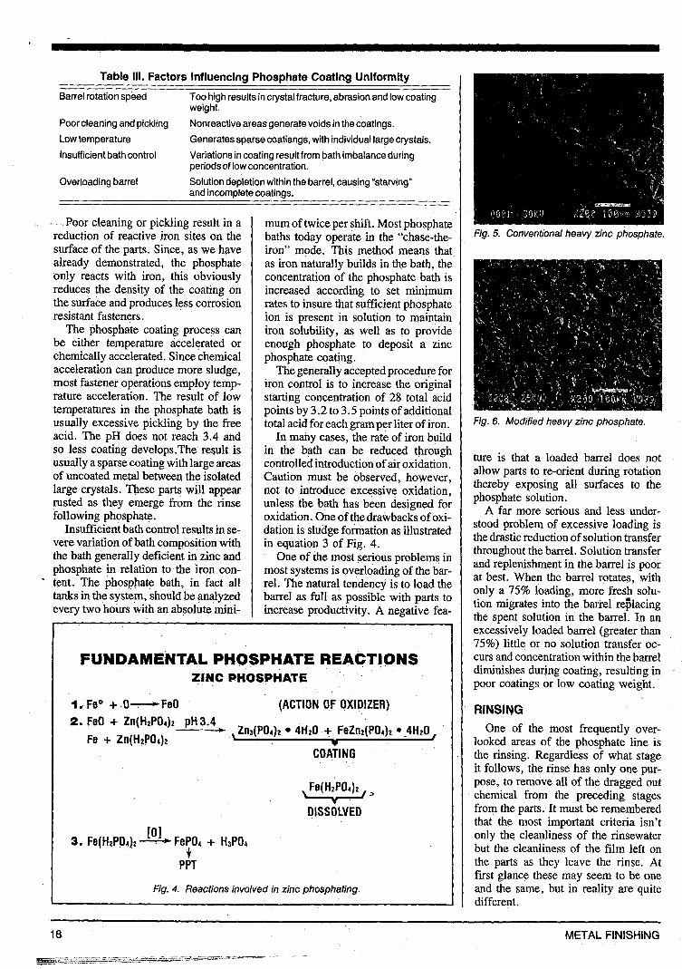
Table 111. Factors Influencing Phosphate Coating Uniformity
Barrel rotation speed Too high results in crystal fracture, abrasion and low coating weight.
Poor cleaning and pickling Low temperature
Nonreactive areas generate voids in the coatings. Generates sparse coatiangs, with individual large crystals.
lnsuff icient bath control Variations in coating result from bath imbalance during periodsof low concentration.
Overloading barrel Solution depletion within the barrel, causing “starving” and incomplete coatings.
I Boor cleaning or pickling result in a reduction of reactive iron sites on the surface of the parts. Since, as we have already demonstrated, the phosphate only reacts with iron, this obviously reduces the density of the coating on the surface and produces less corrosion resistant fasteners.
The phosphate coating process can be either temperature accelerated or chemically accelerated. Since chemical acceleration can produce more sludge, most fastener operations employ temp- rature acceleration. The result of low temperatures in the phosphate bath is usually excessive pickling by the free acid. The pH does not reach 3.4 and so less coating develops.The result is usually a sparse coating with large areas of uncoated metal between the isolated large crystals. These parts will appear rusted as they emerge from the rinse following phosphate.
Insufficient bath control results in se- vere variation of bath composition with the bath generally deficient in zinc and phosphate in relation to the iron con- - tent. The phosphate bath, in fact all tanks in the system, should be analyzed every two hours with an absolute mini-
mum of twice per shift. Most phosphatc baths today operate in the “chase-the iron” mode. This method means tha as iron naturally builds in the bath, thc concentration of the phosphate bath i: increased according to set minimun rates to insure that sufficient phosphatt ion is present in solution to maintair iron solubility, as well as to providr enough phosphate to deposit a zinc phosphate coating.
The generally accepted procedure fo iron control is to increase the origina starting concentration of 28 total acic points by 3.2 to 3.5 points of additiona total acid for each gram per liter of iron
In many cases, the rate of iron builc in the bath can be reduced througl controlled introduction of air oxidation Caution must be observed, however not to introduce excessive oxidation unless the bath has been designed fol oxidation. One of the drawbacks of oxi- dation is sludge formation as illustratec in equation 3 of Fig. 4.
One of the most serious problems ii most systems is overloading of the bar rel. The natural tendency is to load tht barrel as full as possible with parts tc increase productivity. A negative fea
FUNDAMENTAL PHOSPHATE REACTIONS ZINC PHOSPHATE
1. FeO + .O-FeO (ACTION OF OXIDIZER) 2. FeO + Zn(H2P04)2 pH3.4 - ,Zih(P&)z 4H20 + FeZnz(P04)~ .-4H~0,
Fe + Zn(H2PO& COATING
Fe( H2P04)z Y>
DI S SO WED
PPT
Fig. 4. Reactions involved in zinc phosphating.
Fig. 5. Conventional heavy zinc phosphate.
Fig. 6. Modified heavy zinc phosphate.
ture is that a loaded barrel does not allow parts to re-orient during rotation thereby exposing all surfaces to the phosphate solution.
A far more serious and less under- stood problem of excessive loading is the drastic reduction of solution transfer throughout the barrel. Solution transfer and replenishment in the barrel is poor at best. When the barrel rotates, with only a 75% loading, more fresh solu- tion migrates into the barrel reiilacing the spent solution in the barrel. In an excessively loaded barrel (greater than 75%) little or no solution transfer oc- curs and concentration within the barrel diminishes during coating, resulting in poor coatings or low coating weight.
RINSING One of the most frequently over-
looked areas of the phosphate line is the rinsing. Regardless of what stage it follows, the rinse has only one pur- pose, to remove all of the dragged out chemical from the preceding stages from the parts. It must be remembered that the most important criteria isn’t only the cleanliness of the rinsewater but the cleanliness of the film left on the parts as they leave the rinse. At first glance these may seem to be one and the same, but in reality are quite different.
METAL FINISHING 18
II
I ,
I 1 ((
((
((
II c
s C
r
ai fi b)
P’ dl
irr uk
VO stt f c p& OII tr;,
- - Pa
E
1
1 I I PC
$
I
PO) !
Y - - I1
P the: the: ing ing: resii trall ling
H picll dWl batll of u the timu
plett
APR
con
?
-

-
Dhate.
not ion the
ler- 5 is #fer fer )or ith lu- ng an an )C-
re1 in
t.
:r- is Y ir- ut es :d ’t :r in
i t ie :e
- .
For example, parts with a drag-out film of cleaner, quickly dipped into and out of a pure water rinse, will still be heavily soiled with cleaner because the exposure to‘ the rinse wasn’t long enough to completely displace the cleaner film.
Several mechanisms can be em- ployed to improve rinsing. Some are obvious, others less so:
1. Maintain the rinsewater at the specified pH or more effectively, con- ductivity.
2. Extended immersion time in clean rinses.
3. “Double-dip’’ cycles in the rinse, allow all of the rinse solution to drain from the barrel, before being replaced by re-immersion in the rinse.
4. Counterflowing rinses accom- plish *e same principle as “double- dip” cycles and provide cleaner rinse- water for the second immersion at no increase in water consumption.
Drag-in on poorly rinsed parts pre- vents the chemical reaction of the next stage from beginning promptly or uni- formly over the entire surface of the parts. Some examples of problems originating from poor rinsing are illus- trated in Table IV.
Table IV. Effects of Poor Rinsing
Poor rinse after cleaner: 1. Oil redeposition. 2. High pickle acid consumption. 3. Nonuniform pickling.
1. High phosphate bath free acid. 2. Nonuniform sparse coating. 3. Rusty parts after phosphate.
1. Rusty parts. 2. Poor corrosion resistance.
If the oil-saturated cleaner is not completely removed from the parts by the rinse after cleaning, the acid from the pickle will insolubilize the oil forc- ing it to redeposit on the parts, prevent- ing uniform pickling. Additionally, the residual alkalinity on the surface neu- tralizes the pickle acid, reducing pick- ling.
Poor rinsing after pickling will leave pickle solution on the parts effectively dragging pickle into the phosphate bath. This drag-in raises the free acid of the phosphate, effectively lowering the total acid/free acid ratio below op- timum for phosphate deposition.
The phosphate solution must be com- pletely rinsed from both the surface of
Poor rinse after pickle:
Poor rinse after phosphate:
the phosphate and from between the phosphate crystals. Residual phosphate solution will ultimately redissolve dur- ing corrosion testing causing blisters in paint films or downgraded performance of corrosion inhibiting oils.
If the phosphatgd fasteners are to be painted, it is common to employ e chromic seal to insolubilize dragged ou1 hydroscopic salts on the surface (suck as phosphate bath, drag-out), but ii rinsing is poor enough, even this final seal is not adequate to negate the effectz of poor rinsing.
If the final fastener finish is to be s phosphate and oil type, excessive phos. phate drag-in to the emulsion oil wil reduce pH, causing the emulsion tc split. The rinse after phosphate mus completely remove the phosphate solu. tion from the parts.
CONCLUSION The success of any pretreatment sys.
tem for fasteners is based on the stric adherence to logical principles. Mos fastener finish failures can be tracec directly back to violation of these prin ciples. When attempting to prevent o solve problems in those systems, i thoughtful study of what purpose ead step in the system serves will usual11 guide the inquiry back to these basic concepts. MI
Biography Roger Kelly i!
business manager small parts finish ing, at Man-Gil Chemical Co. Cleveland, OH. Hc obtained his chemi cal engineering de gree from Cleve land State LJniver
sity. For the past 30 years Roger ha been involved in all areas of meta finishing, primarily in technical ser vice.
Send for our free book list
Metal Finishing 1 University Plaza
Hackensack, NJ 07601
Has The Filtration System FOR YOUR PLATING NEEDS!
Whether your job requires - a compact small volume filter - or continuous depth filtration - or heavy volume filtering up to 10,000 GPH - Beaver Industries has the system for you.
Designed and built for troublefree, long lasting, low maintenance use. 0 Made of corrosion resistant,
stress-relieved polypropylene 0 Operated with magnetic driven
Pumps 0 Easy to replace filters 0 Carbon treatment systems
available Beaver Industries
Providing Pumps and Filtration Systems to Today’s Platers
Circle 11 1 on reader Informatlon card
A D D 1 1 in00