principles of fluid mixing
TRANSCRIPT
8/10/2019 Principles of Fluid Mixing
http://slidepdf.com/reader/full/principles-of-fluid-mixing 1/20
Principles
of FluidMixing
A Professional Resource for Engineered Mixing Success
8/10/2019 Principles of Fluid Mixing
http://slidepdf.com/reader/full/principles-of-fluid-mixing 2/20

8/10/2019 Principles of Fluid Mixing
http://slidepdf.com/reader/full/principles-of-fluid-mixing 3/[email protected] • (616) 399-5600 • www.brawnmixer.com • © BRAWN MIXER, INC | 3
Principles of Fluid Mixing
Mixer Types
Mixer Types: Many mixer types are available. Some mixers are specically designed
for one special application, while other mixers are more versatile with many options
such as variable speed, changeable impellers and shafts, and a wide range of motorhorsepower. This list of mixer types will clarify some of the designations commonly
used when referring to industrial mixers.
Aerator: A mixer or other device used to dissolveair into water; usually for biological waste treatment.It may operate at the surface by splashing, or besubmerged with a pipe, or with a sparge providingair to the impeller.
Air: A mixer with a motor powered by compressedair instead of electricity is sometimes called an airmixer, an air-drive mixer, or a pneumatic mixer.
Bottom Entry: A mixer with its drive mounted tothe bottom head of a vessel. The mixer shaft entersthrough the tank bottom.
Direct Drive: A mixer with an output shaft thatrotates at the same speed as the motor. Direct-drivemixers are relatively simple and offer a higher com-ponent of shear to the process.
Disperser: A special-purpose, high-shear mixer;or just the blade or impeller. Typically a high-speeddevice often with sharp edges (some look likecircular saw blades with bent teeth) used to breakup powders or particles to dissolve or suspend them(see Rotor Stator).
Flocculator: A relatively slow-RPM mixer thatis used to enhance the contact of particles insuspension to agglomerate them for easier settlingor separation.
Gear Drive: A mixer with an output shaft that hasa speed lower than the motor speed because of agear reducer between the motor and output shaft.This mixer transmits higher torque and has higher
pumping efciency per horsepower.Homogenizer: A very high-speed mixer used toblend immiscible phases of a solution into a creamor emulsion.
Magnetic Drive: A mixer with its shaft and impellerdriven by a magnet. The internal mixer shaft isdriven by a magnetic eld. The driven shaft doesnot penetrate the vessel affording ‘seal-less’ mixing.
Portable: A mixer that is relatively easily movedfrom tank to tank and mounted to tank walls with a
C-clamp or adjustable plate mount.
Rotor Stator: A type of high-shear mixer thatutilizes a rotating head/impeller inside a stationaryshroud or cage.
Sanitary: A mixer with drive components (motor,gearbox) that are made from stainless steel or otherapproved materials. These mixers are used in san-itary and washdown environments, as well as highlycorrosive atmospheres.
Side Entry: A mixer mounted on a ange throughthe side of a tank or chest; often used for very talltanks to reduce capital cost.
Static: A mixer made of pipes with speciallydesigned bafes inside that blend uids as the uidsow through the pipe. These mixers do not haveany moving parts.
Top Entry: A mixer mounted on the rim, on beams,or on a ange entering from the top of the tank.
8/10/2019 Principles of Fluid Mixing
http://slidepdf.com/reader/full/principles-of-fluid-mixing 4/204 | © BRAWN MIXER, INC. • www.brawnmixer.com • (616) 399-5600 • [email protected]
Principles of Fluid Mixing
Mixer Terminology
Axial Flow: Fluid ow axially directed along themixer shaft from top to bottom (down-pumping); orfrom bottom to top (up-pumping).
Bafes: Structures attached to an inside tankstraight side, either directly or on tabs, to verticallydirect uid ow in the tank; preventing swirl andvortexing.
Bending Moment: The product of force timesdistance. Fluid forces are exerted on a mixer shaftat each impeller. The force (lbs) times the distancefrom the impeller to the lowest shaft bearing (in) is
the bending moment (in – lb). For multiple impel-lers, the shaft bending moment is the sum of theindividual bending moments.
Bulk Fluid Velocity: The primary pumping rate ofa mixer divided by the plan, cross-sectional area ofthe mixed vessel.
Case Size: Speed reducer size on gear-drivenmixers. When torque design limits are reached, or
when a larger diameter shaft is required to meetother design criteria, the next larger size gear box(case size) must be used. A given case size mayaccommodate many various horsepower and input/output speed combinations, but carries the sametorque and shaft size.
Coverage: The distance between the impeller andthe liquid surface. Typical optimum coverage isequal to twice the impeller diameter. Insufcient
coverage may cause vortexing and/or air entrain-ment.
Critical Speed: A rotational speed (rpm) of amixer shaft which is operating at the shaft’s naturalvibration frequency (cycles/min). Operating a shaftat critical speed may amplify vibrations leading toshaft failure by excessive deection.
D/T: The ratio of impeller diameter (D) to tank
diameter (T).
Dry Well Mixer: A vertically-mounted mixer whichutilizes a gear drive that has an oil dam called a “drywell” around the output shaft. The oil dam extends
above the oil level of the gearbox so that the oilcannot run out of the gearbox during operation.
Equivalent Weight: A calculated value represent-ing the combined impeller weight at the shaft endwhen several impellers are installed on a shaft.
Entrainment: The result of the drawing forceproduced by a owing uid, which drags additionaluid (entrained ow) or air (air entrainment) along
with the pumped uid.
Flow: One of two components resulting from theaction of a mixer impeller (see Shear). The bulkmovement of the uid. Primary impeller pumpingrate measured in gallons per minute is oftenreferred to as ow.
Fluid Force: The forces exerted on a mixer shaftthrough the impeller as a result of the uid motion
in the tank. Fluid forces are calculated for eachimpeller and used to calculate the shaft bendingmoment.
Frame Size: Relating to the physical size of amotor. Frame size is dependent on motor HP,enclosure, speed, power supply voltage and phase.Example: ½ HP, 1800 RPM, 230/460V has a NEMA56 frame; 3 HP, 1800 RPM, 230/460V has a NEMA182 frame.
Freeboard: The distance from the liquid surfaceto the top of a tank. This distance must be takeninto account when sizing a mixer shaft to ensureadequate coverage.
Free Flow / Plug Flow: The unobstructed owof a uid. Mixer characteristics, such as pumpingcapacity and power requirement, are based on theassumption that no obstructions or ow constric-
tions are present.
HP (Horsepower): A unit for measuring the powerof motors, equal to 746 Watts. In mixer applica-tions, horsepower may be expressed as shaft HPor motor HP.
8/10/2019 Principles of Fluid Mixing
http://slidepdf.com/reader/full/principles-of-fluid-mixing 5/[email protected] • (616) 399-5600 • www.brawnmixer.com • © BRAWN MIXER, INC | 5
Principles of Fluid Mixing
Mixer Terminology
Impeller: The device responsible for the actualmixing action in a process. The rotating impeller isresponsible for ow and shear imparted to the uid
as it rotates.
MHP (Motor Horsepower): The actual shaft horse-power, divided by motor efciency, determines therequired motor nameplate horsepower.
Np (Power number): A constant, unique to eachtype of mixing impeller, used to calculate powerdraw. Power number varies with Reynolds number,but may be treated, as a constant if the Reynolds
number is sufciently high.
NQ (Flow number): A constant, derived empiricallyfor each unique geometric shape of mixing impeller,used to calculate ow or pumping rate.
Off-Bottom: The distance from the impeller to thetank bottom. Typically, the off-bottom is betweenone- to two-times the impeller diameter.
Prandtl Number: A dimensionless number used toestimate the boundary layer lm co-efcient in heattransfer calculations. In uids, Prandtl numberscannot be estimated accurately and therefore mustbe derived experimentally.
Q: Flow or pumping rate, measured in gallonsper minute, which is the actual discharge rate of aspecic size and type of mixing impeller.
Radial Flow: Movement of uid drawn from aboveand below the impeller and perpendicularly dis-charged toward the tank wall, from the mixer shaft.
Reynolds Number: A dimensionless number usedto indicate the type of uid motion being produced.The value of this number determines the valueof the Power number, which affects the HP draw.Reynolds numbers below 1,000 are consideredlaminar; above 2,500 is turbulent ow.
Right-Angle Mixer: A mixer with the motor shaftinput perpendicular to the gearbox output shaft.The motor suspends off the side of the gearbox,keeping the required headroom to a minimum.
Service Factor: Equipment having a service factorof 1.0, for a given level of performance, is designedto operate without excessive wear or failure over
its lifetime at that performance level. For instance,a 1 HP motor rotating, at 1725 RPM, with a servicefactor of 1.0, will operate for many years under a1 HP load. A gearbox designed to transmit 1 HPhas a service factor of 1.0 when loaded to 1 HP. If,however, that same gearbox is loaded to only ½ HP,it now has a service factor of 2.0, indicating that itis capable of heavier duty than the current use andshould have a longer service life.
Shaft Stress: The intensity of the straining forceon a mixer shaft that tends to deform shaft shapeor cause the shaft to fracture; usually expressedin PSI. Shaft stress is calculated from the bendingmoment. Stress limits are known for various mate-rials under static loads. For mixer shafts which aresubjected to alternating stresses because of theirrotation, a fatigue stress limit must be establishedwhich is much less than the static limit. Mixers
should not be designed with a shaft stress higherthan 15,000 PSI.
Shear: One of two components resulting from theaction of a mixer impeller (see Flow). Differentvelocities existing simultaneously (velocity gradient= shear rate) which produce stresses on the uid.Shear rate X viscosity = shear stress in PSI. Shearstress is responsible for small scale uid intermixing.
SHP (Shaft Horsepower): The actual powerrequired to drive the mixer impeller in the specicprocess uid at the rotational speed supplied to themixer shaft.
Specic Gravity: The ratio of uid density E.G.(lb/gal) to the density of water (8.33 lb/gal @ 25°C,1 atm pressure) under current conditions.
T: Tank diameter.
Tip Speed: The peripheral speed of a rotatingimpeller. Tip speed is used to estimate the shearapplied to a uid. Tip Speed = RPM X D X π.

8/10/2019 Principles of Fluid Mixing
http://slidepdf.com/reader/full/principles-of-fluid-mixing 6/206 | © BRAWN MIXER, INC. • www.brawnmixer.com • (616) 399-5600 • [email protected]
Principles of Fluid Mixing
Mixer Terminology
Torque: The twisting force that is created by amotor and/or gearbox to produce rotation of a mixershaft.
Velocity Head: For the mixer concepts presentedhere, velocity head and shear have the samemeaning (see Shear).
Viscosity: Internal uid friction. The property of auid that enables the uid to develop and maintainan amount of shearing stress dependent uponthe velocity of ow; and then to offer continuedresistance to ow.
Z: The designation used to signify the liquid level orheight in a tank.
8/10/2019 Principles of Fluid Mixing
http://slidepdf.com/reader/full/principles-of-fluid-mixing 7/[email protected] • (616) 399-5600 • www.brawnmixer.com • © BRAWN MIXER, INC | 7
Principles of Fluid Mixing
BAFFLE
Z
T
OFF BOTTOM
COVERAGE
FREEBOARD
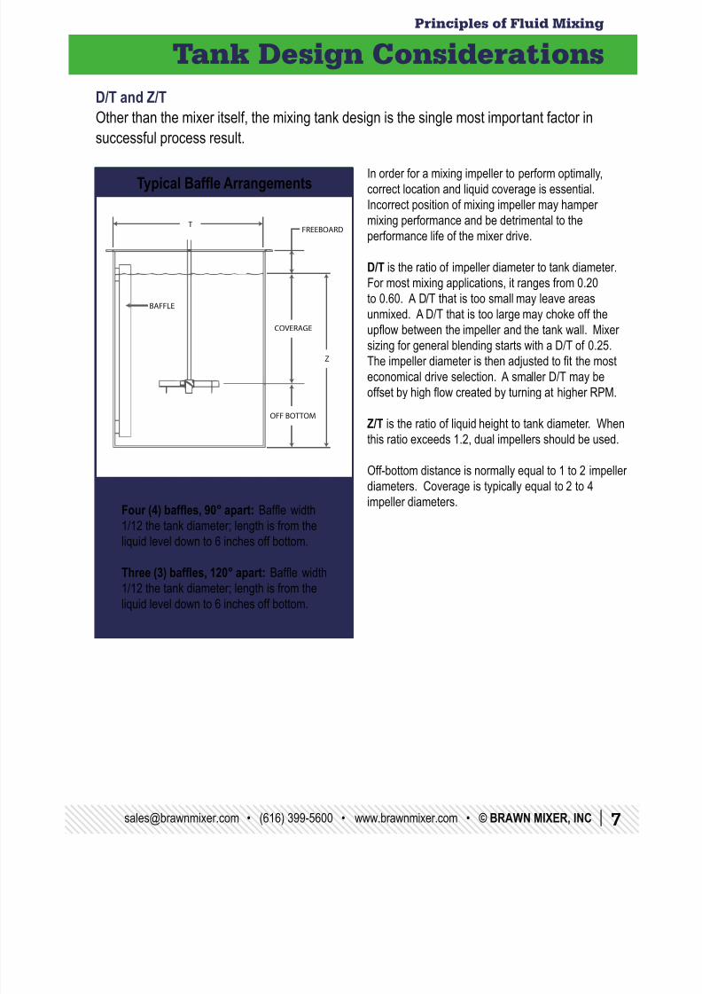
Tank Design Considerations
D/T and Z/T
Other than the mixer itself, the mixing tank design is the single most important factor in
successful process result.
In order for a mixing impeller to perform optimally,
correct location and liquid coverage is essential.
Incorrect position of mixing impeller may hamper
mixing performance and be detrimental to the
performance life of the mixer drive.
D/T is the ratio of impeller diameter to tank diameter.
For most mixing applications, it ranges from 0.20to 0.60. A D/T that is too small may leave areas
unmixed. A D/T that is too large may choke off the
upow between the impeller and the tank wall. Mixer
sizing for general blending starts with a D/T of 0.25.
The impeller diameter is then adjusted to t the most
economical drive selection. A smaller D/T may be
offset by high ow created by turning at higher RPM.
Z/T is the ratio of liquid height to tank diameter. Whenthis ratio exceeds 1.2, dual impellers should be used.
Off-bottom distance is normally equal to 1 to 2 impeller
diameters. Coverage is typically equal to 2 to 4
impeller diameters.Four (4) bafes, 90° apart: Bafe width
1/12 the tank diameter; length is from the
liquid level down to 6 inches off bottom.
Three (3) bafes, 120° apart: Bafe width1/12 the tank diameter; length is from the
liquid level down to 6 inches off bottom.
Typical Bafe Arrangements
8/10/2019 Principles of Fluid Mixing
http://slidepdf.com/reader/full/principles-of-fluid-mixing 8/208 | © BRAWN MIXER, INC. • www.brawnmixer.com • (616) 399-5600 • [email protected]
Principles of Fluid Mixing
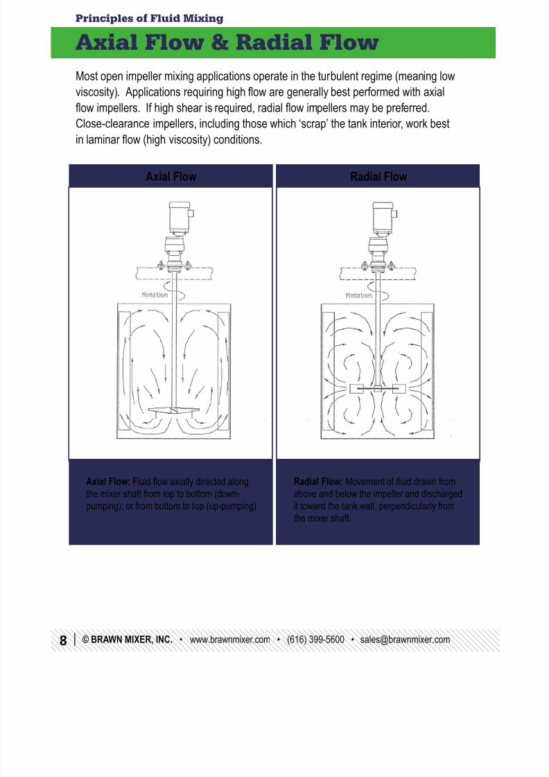
Radial Flow: Movement of uid drawn from
above and below the impeller and discharged
it toward the tank wall, perpendicularly from
the mixer shaft.
Axial Flow & Radial Flow
Axial Flow Radial Flow
Most open impeller mixing applications operate in the turbulent regime (meaning low
viscosity). Applications requiring high ow are generally best performed with axial
ow impellers. If high shear is required, radial ow impellers may be preferred.Close-clearance impellers, including those which ‘scrap’ the tank interior, work best
in laminar ow (high viscosity) conditions.
Axial Flow: Fluid ow axially directed along
the mixer shaft from top to bottom (down-
pumping); or from bottom to top (up-pumping).
8/10/2019 Principles of Fluid Mixing
http://slidepdf.com/reader/full/principles-of-fluid-mixing 9/[email protected] • (616) 399-5600 • www.brawnmixer.com • © BRAWN MIXER, INC | 9
Principles of Fluid Mixing
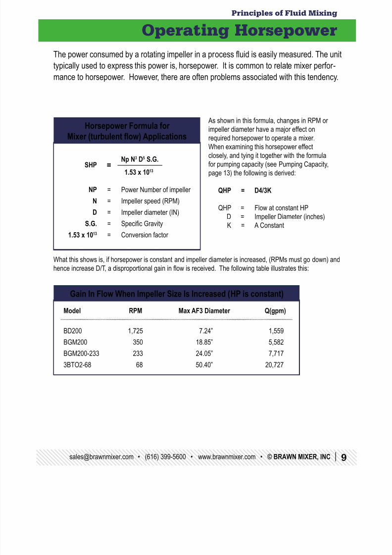
Operating Horsepower
Gain In Flow When Impeller Size Is Increased (HP is constant)
The power consumed by a rotating impeller in a process uid is easily measured. The unit
typically used to express this power is, horsepower. It is common to relate mixer perfor -
mance to horsepower. However, there are often problems associated with this tendency.
What this shows is, if horsepower is constant and impeller diameter is increased, (RPMs must go down) and
hence increase D/T, a disproportional gain in ow is received. The following table illustrates this:
Horsepower Formula forMixer (turbulent ow) Applications
SHP = Np N3 D5 S.G.
1.53 x 10¹³
NP = Power Number of impeller
N = Impeller speed (RPM)
D = Impeller diameter (IN)
S.G. = Specic Gravity
1.53 x 1013 = Conversion factor
As shown in this formula, changes in RPM or
impeller diameter have a major effect on
required horsepower to operate a mixer.
When examining this horsepower effect
closely, and tying it together with the formula
for pumping capacity (see Pumping Capacity,
page 13) the following is derived:
QHP = D4/3K
QHP = Flow at constant HP
D = Impeller Diameter (inches)
K = A Constant
Model RPM Max AF3 Diameter Q(gpm)
BD200 1,725 7.24” 1,559
BGM200 350 18.85” 5,582
BGM200-233 233 24.05” 7,717
3BTO2-68 68 50.40” 20,727
8/10/2019 Principles of Fluid Mixing
http://slidepdf.com/reader/full/principles-of-fluid-mixing 10/2010 | © BRAWN MIXER, INC. • www.brawnmixer.com • (616) 399-5600 • [email protected]
Principles of Fluid Mixing
Operating Horsepower
Viscosity Effect As described in Reynolds Numbers (see page 11), as viscosity increases, impeller
power number may begin to increase. This becomes important in the HP calculationsbecause as power number begins to go up so does the horsepower required to drive
the mixer. Simply increasing the input horsepower may be the answer, but one must
bear in mind that this change reduces the service factor of the mixer drive, hence a
differently sized mixer may be required.
Viscosity increase also effects the ow characteristics of uid as compared to water.
A correction factor may be obtained from a qualied mixer application engineer.
However, most viscous uids should be checked in the lab to obtain a predictableviscosity prole.
Multiple ImpellersMore than one impeller may be required for some processes. This may be due to tank
geometry or uid characteristics. Regardless of how many impellers are required or
why, it is important to realize the multiple effect on horsepower required.
8/10/2019 Principles of Fluid Mixing
http://slidepdf.com/reader/full/principles-of-fluid-mixing 11/[email protected] • (616) 399-5600 • www.brawnmixer.com • © BRAWN MIXER, INC | 11
Principles of Fluid Mixing
Reynolds Numbers
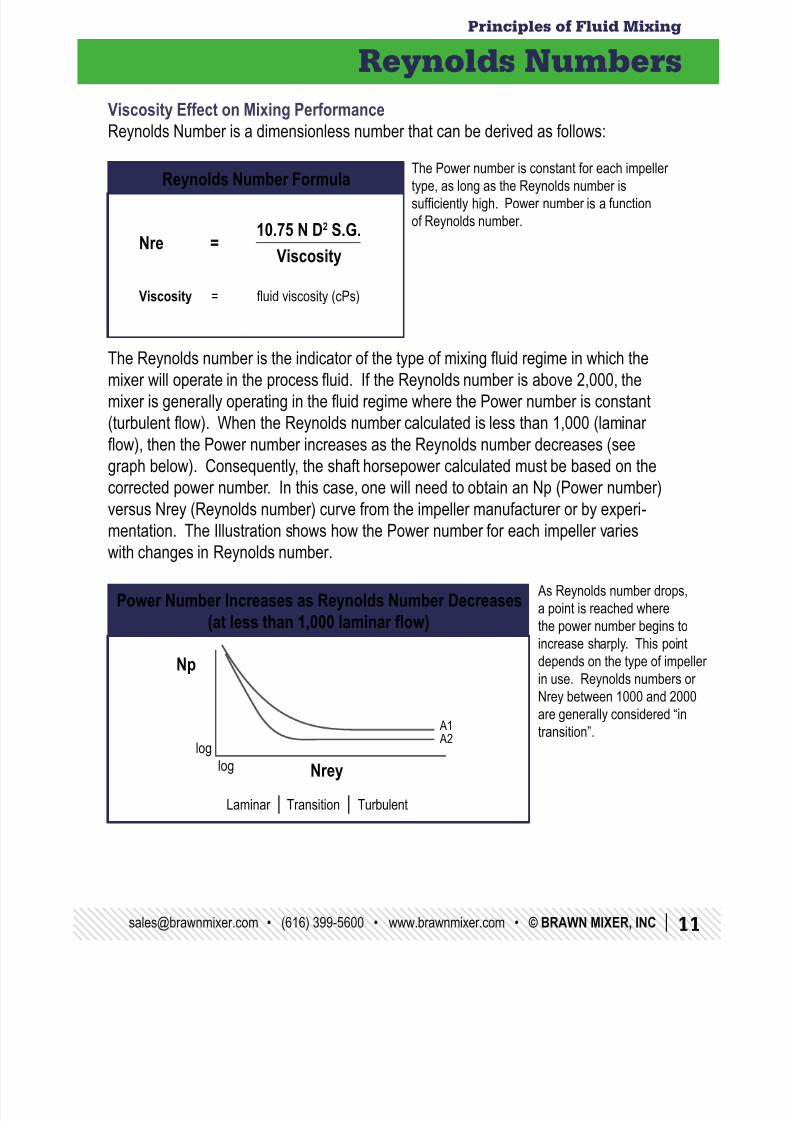
Viscosity Effect on Mixing PerformanceReynolds Number is a dimensionless number that can be derived as follows:
The Reynolds number is the indicator of the type of mixing uid regime in which the
mixer will operate in the process uid. If the Reynolds number is above 2,000, the
mixer is generally operating in the uid regime where the Power number is constant
(turbulent ow). When the Reynolds number calculated is less than 1,000 (laminar
ow), then the Power number increases as the Reynolds number decreases (see
graph below). Consequently, the shaft horsepower calculated must be based on the
corrected power number. In this case, one will need to obtain an Np (Power number)versus Nrey (Reynolds number) curve from the impeller manufacturer or by experi-
mentation. The Illustration shows how the Power number for each impeller varies
with changes in Reynolds number.
Nre = 10.75 N D2 S.G.
Viscosity
Viscosity = uid viscosity (cPs)
Reynolds Number Formula
Power Number Increases as Reynolds Number Decreases(at less than 1,000 laminar ow)
Np
log
A1 A2
Laminar | Transition | Turbulent
log Nrey
The Power number is constant for each impeller
type, as long as the Reynolds number is
sufciently high. Power number is a function
of Reynolds number.
As Reynolds number drops,
a point is reached where
the power number begins to
increase sharply. This pointdepends on the type of impeller
in use. Reynolds numbers or
Nrey between 1000 and 2000
are generally considered “in
transition”.
8/10/2019 Principles of Fluid Mixing
http://slidepdf.com/reader/full/principles-of-fluid-mixing 12/2012 | © BRAWN MIXER, INC. • www.brawnmixer.com • (616) 399-5600 • [email protected]
Principles of Fluid Mixing
Power Numbers
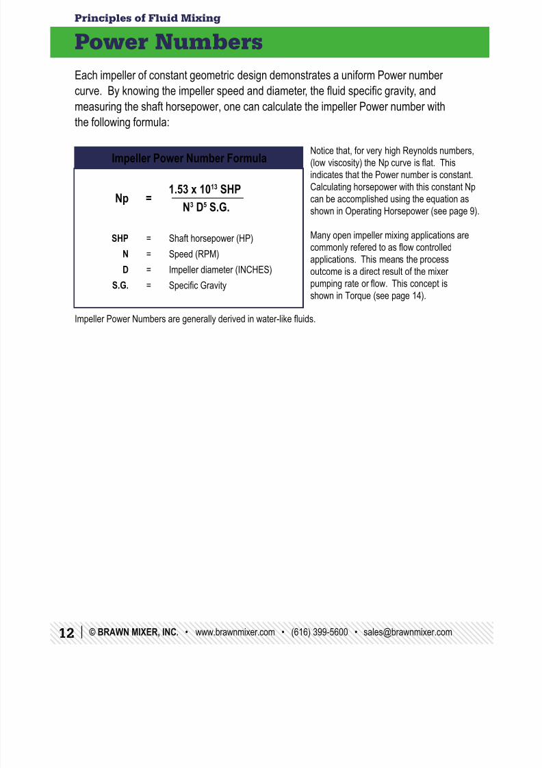
Each impeller of constant geometric design demonstrates a uniform Power number
curve. By knowing the impeller speed and diameter, the uid specic gravity, and
measuring the shaft horsepower, one can calculate the impeller Power number withthe following formula:
Impeller Power Numbers are generally derived in water-like uids.
Impeller Power Number Formula
Np =
1.53 x 10¹³ SHP
N3 D5 S.G.
SHP = Shaft horsepower (HP)
N = Speed (RPM)
D = Impeller diameter (INCHES)
S.G. = Specic Gravity
Notice that, for very high Reynolds numbers,
(low viscosity) the Np curve is at. This
indicates that the Power number is constant.
Calculating horsepower with this constant Np
can be accomplished using the equation as
shown in Operating Horsepower (see page 9).
Many open impeller mixing applications are
commonly refered to as ow controlled
applications. This means the process
outcome is a direct result of the mixer
pumping rate or ow. This concept is
shown in Torque (see page 14).
8/10/2019 Principles of Fluid Mixing
http://slidepdf.com/reader/full/principles-of-fluid-mixing 13/[email protected] • (616) 399-5600 • www.brawnmixer.com • © BRAWN MIXER, INC | 13
Principles of Fluid Mixing
Pumping Capacity or Flow
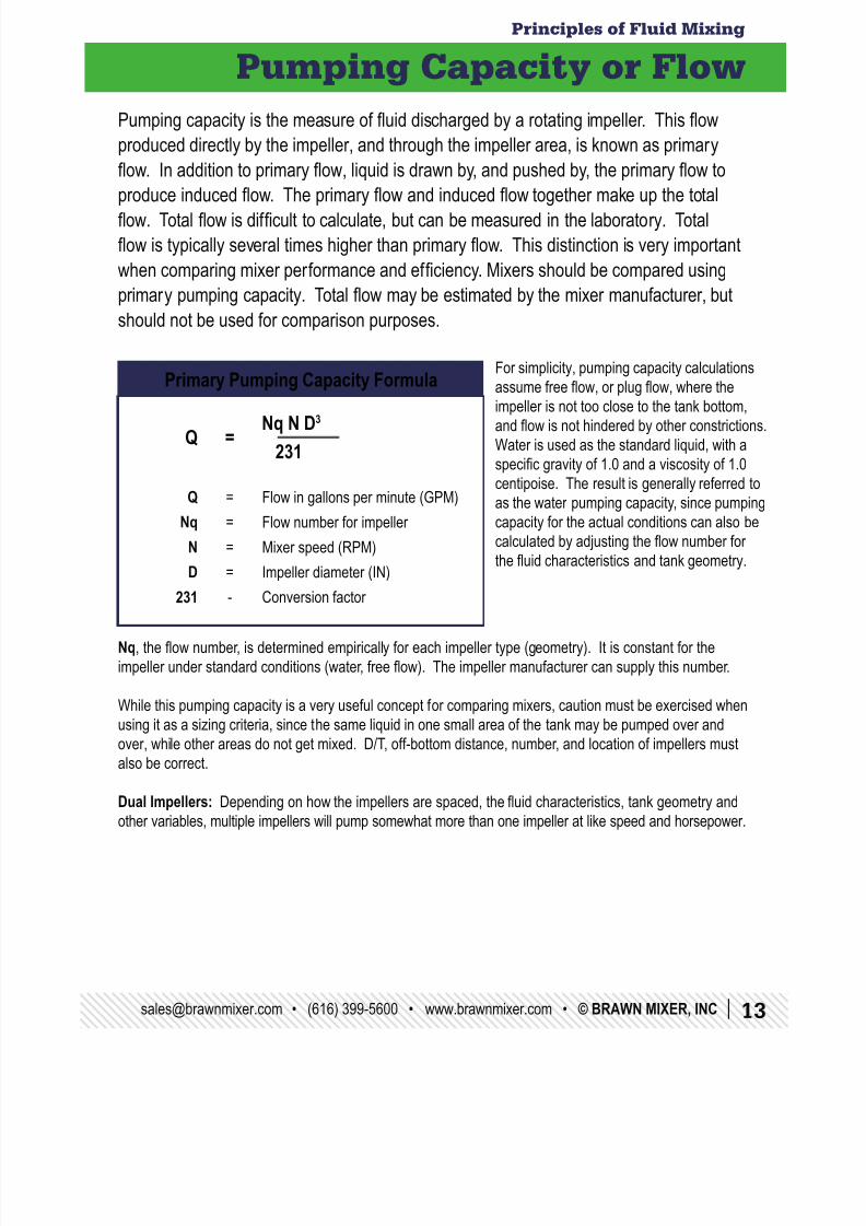
Pumping capacity is the measure of uid discharged by a rotating impeller. This ow
produced directly by the impeller, and through the impeller area, is known as primary
ow. In addition to primary ow, liquid is drawn by, and pushed by, the primary ow toproduce induced ow. The primary ow and induced ow together make up the total
ow. Total ow is difcult to calculate, but can be measured in the laboratory. Total
ow is typically several times higher than primary ow. This distinction is very important
when comparing mixer performance and efciency. Mixers should be compared using
primary pumping capacity. Total ow may be estimated by the mixer manufacturer, but
should not be used for comparison purposes.
Nq, the ow number, is determined empirically for each impeller type (geometry). It is constant for the
impeller under standard conditions (water, free ow). The impeller manufacturer can supply this number.
While this pumping capacity is a very useful concept for comparing mixers, caution must be exercised whenusing it as a sizing criteria, since the same liquid in one small area of the tank may be pumped over and
over, while other areas do not get mixed. D/T, off-bottom distance, number, and location of impellers must
also be correct.
Dual Impellers: Depending on how the impellers are spaced, the uid characteristics, tank geometry and
other variables, multiple impellers will pump somewhat more than one impeller at like speed and horsepower.
Primary Pumping Capacity Formula
Q =
Nq N D3
231
Q = Flow in gallons per minute (GPM)
Nq = Flow number for impeller N = Mixer speed (RPM)
D = Impeller diameter (IN)
231 - Conversion factor
For simplicity, pumping capacity calculations
assume free ow, or plug ow, where the
impeller is not too close to the tank bottom,
and ow is not hindered by other constrictions.
Water is used as the standard liquid, with a
specic gravity of 1.0 and a viscosity of 1.0
centipoise. The result is generally referred to
as the water pumping capacity, since pumping
capacity for the actual conditions can also becalculated by adjusting the ow number for
the uid characteristics and tank geometry.
8/10/2019 Principles of Fluid Mixing
http://slidepdf.com/reader/full/principles-of-fluid-mixing 14/2014 | © BRAWN MIXER, INC. • www.brawnmixer.com • (616) 399-5600 • [email protected]
Principles of Fluid Mixing
Torque
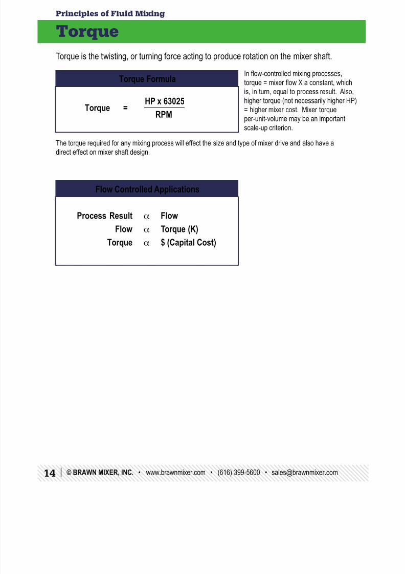
Torque is the twisting, or turning force acting to produce rotation on the mixer shaft.
The torque required for any mixing process will effect the size and type of mixer drive and also have a
direct effect on mixer shaft design.
Torque Formula
Flow Controlled Applications
Torque = HP x 63025
RPM
Process Result a Flow
Flow a Torque (K)
Torque a $ (Capital Cost)
In ow-controlled mixing processes,
torque = mixer ow X a constant, whichis, in turn, equal to process result. Also,
higher torque (not necessarily higher HP)
= higher mixer cost. Mixer torque
per-unit-volume may be an important
scale-up criterion.
8/10/2019 Principles of Fluid Mixing
http://slidepdf.com/reader/full/principles-of-fluid-mixing 15/[email protected] • (616) 399-5600 • www.brawnmixer.com • © BRAWN MIXER, INC | 15
Principles of Fluid Mixing
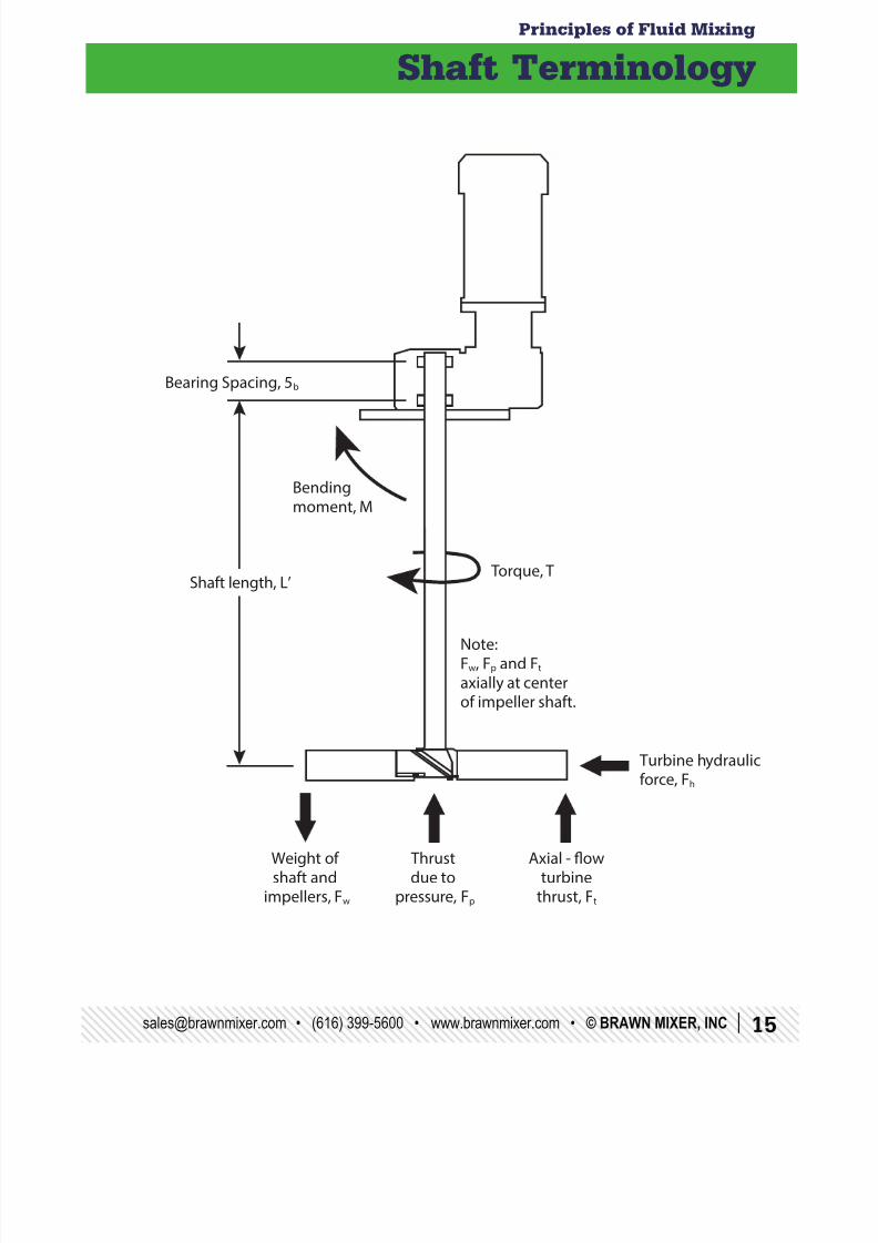
Shaft Terminology
Bearing Spacing, 5b
Shaft length, L’ Torque, T
Note:Fw, Fp and Ft axially at centerof impeller shaft.
Axial - flowturbine
thrust, Ft
Thrustdue to
pressure, Fp
Weight ofshaft and
impellers, Fw
Turbine hydraulicforce, Fh
Bendingmoment, M
8/10/2019 Principles of Fluid Mixing
http://slidepdf.com/reader/full/principles-of-fluid-mixing 16/2016 | © BRAWN MIXER, INC. • www.brawnmixer.com • (616) 399-5600 • [email protected]
Principles of Fluid Mixing
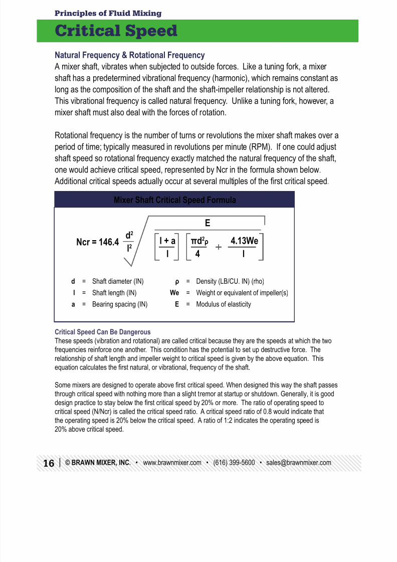
Critical Speed
Natural Frequency & Rotational Frequency
A mixer shaft, vibrates when subjected to outside forces. Like a tuning fork, a mixer
shaft has a predetermined vibrational frequency (harmonic), which remains constant aslong as the composition of the shaft and the shaft-impeller relationship is not altered.
This vibrational frequency is called natural frequency. Unlike a tuning fork, however, a
mixer shaft must also deal with the forces of rotation.
Rotational frequency is the number of turns or revolutions the mixer shaft makes over a
period of time; typically measured in revolutions per minute (RPM). If one could adjust
shaft speed so rotational frequency exactly matched the natural frequency of the shaft,one would achieve critical speed, represented by Ncr in the formula shown below.
Additional critical speeds actually occur at several multiples of the rst critical speed.
Critical Speed Can Be DangerousThese speeds (vibration and rotational) are called critical because they are the speeds at which the two
frequencies reinforce one another. This condition has the potential to set up destructive force. The
relationship of shaft length and impeller weight to critical speed is given by the above equation. This
equation calculates the rst natural, or vibrational, frequency of the shaft.
Some mixers are designed to operate above rst critical speed. When designed this way the shaft passes
through critical speed with nothing more than a slight tremor at startup or shutdown. Generally, it is good
design practice to stay below the rst critical speed by 20% or more. The ratio of operating speed tocritical speed (N/Ncr) is called the critical speed ratio. A critical speed ratio of 0.8 would indicate that
the operating speed is 20% below the critical speed. A ratio of 1:2 indicates the operating speed is
20% above critical speed.
Mixer Shaft Critical Speed Formula
d = Shaft diameter (IN)
l = Shaft length (IN)
a = Bearing spacing (IN)
ρ = Density (LB/CU. IN) (rho)
We = Weight or equivalent of impeller(s)
E = Modulus of elasticity
Ncr = 146.4
E
d2
l2 l + al
πd2
ρ 4.13We 4 l
8/10/2019 Principles of Fluid Mixing
http://slidepdf.com/reader/full/principles-of-fluid-mixing 17/[email protected] • (616) 399-5600 • www.brawnmixer.com • © BRAWN MIXER, INC | 17
Principles of Fluid Mixing
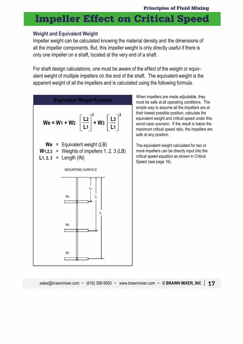
Impeller Effect on Critical Speed
Weight and Equivalent Weight
Impeller weight can be calculated knowing the material density and the dimensions of
all the impeller components. But, this impeller weight is only directly useful if there isonly one impeller on a shaft, located at the very end of a shaft.
For shaft design calculations, one must be aware of the effect of the weight or equiv-
alent weight of multiple impellers on the end of the shaft. The equivalent weight is the
apparent weight of all the impellers and is calculated using the following formula.
Equivalent Weight Formula
We = Equivalent weight (LB)
W1,2,3 = Weights of impellers 1, 2, 3 (LB)
L1, 2, 3 = Length (IN)
L2
L1
L3
L1We = W1 + W2
3 3
+ W3
MOUNTING SURFACE
W3
W2
L1
L2
L3
W1
When impellers are made adjustable, theymust be safe at all operating conditions. The
simple way to assume all the impellers are at
their lowest possible position, calculate the
equivalent weight and critical speed under this
worst-case scenario. If the result is below the
maximum critical speed ratio, the impellers are
safe at any position.
The equivalent weight calculated for two or
more impellers can be directly input into the
critical speed equation as shown in Critical
Speed (see page 16).
8/10/2019 Principles of Fluid Mixing
http://slidepdf.com/reader/full/principles-of-fluid-mixing 18/2018 | © BRAWN MIXER, INC. • www.brawnmixer.com • (616) 399-5600 • [email protected]
Principles of Fluid Mixing
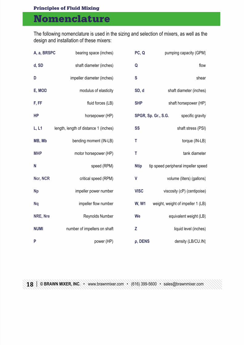
Nomenclature
The following nomenclature is used in the sizing and selection of mixers, as well as the
design and installation of these mixers:
A, a, BRSPC bearing space (inches) PC, Q pumping capacity (GPM)
d, SD shaft diameter (inches) Q ow
D impeller diameter (inches) S shear
E, MOD modulus of elasticity SD, d shaft diameter (inches)
F, FF uid forces (LB) SHP shaft horsepower (HP)
HP horsepower (HP) SPGR, Sp. Gr., S.G. specic gravity
L, L1 length, length of distance 1 (inches) SS shaft stress (PSI)
MB, Mb bending moment (IN-LB) T torque (IN-LB)
MHP motor horsepower (HP) T tank diameter
N speed (RPM) Ntip tip speed peripheral impeller speed
Ncr, NCR critical speed (RPM) V volume (liters) (gallons)
Np impeller power number VISC viscosity (cP) (centipoise)
Nq impeller ow number W, W1 weight, weight of impeller 1 (LB)
NRE, Nre Reynolds Number We equivalent weight (LB)
NUMI number of impellers on shaft Z liquid level (inches)
P power (HP) ρ, DENS density (LB/CU.IN)

8/10/2019 Principles of Fluid Mixing
http://slidepdf.com/reader/full/principles-of-fluid-mixing 19/[email protected] • (616) 399-5600 • www.brawnmixer.com • © BRAWN MIXER, INC | 19

8/10/2019 Principles of Fluid Mixing
http://slidepdf.com/reader/full/principles-of-fluid-mixing 20/20
BRAWN MIXER, INC.3389 128th Ave.
Holland, MI 49424
Phone: (616) 399-5600