principles of vsds
TRANSCRIPT

8/13/2019 Principles of VSDs
http://slidepdf.com/reader/full/principles-of-vsds 1/23
Principles of Induction Motors and Drives Page 14501-100 Rev D
CHAPTER 1: PRINCIPLES OF SQUIRREL CAGE INDUCTION MOTOR
1.1 Construction of Squirrel Cage Induction Motor
The three phase induction motor is by far the most common one used in industry. It is efficient, reliable andrugged. It is used to drive pumps, fans, conveyors, mixers, grinders, saws, and on all types of machinery. Itis powered from the standard three phase industrial electricity supply.
BEARING
STATOR STACK
STATORWINDINGS
COOLING FANFITTED TO SHAFT
BEARING
ROTORFRAME
SHAFT
4501-011 Rev B
Figure 1.1: Cross-Sectional View of 3-Phase Induction Motor
Refer to Figure 1.1. The body of the motor is called the frame. It is usually made of cast iron or aluminium.Fixed into the frame is a part in the shape of a hollow tube, called the stator. Spinning inside this is therotor, which is as solid cylindrical item with a shaft through its centre. The shaft runs in low friction bearings.
1.2 Stator Construction and Excitation
Refer to Figure 1.2(a). The stator is built up a silicon steel punchings, and assembled as a hollow cylinderinside the motor frame. A distributed three-phase winding is arranged in slots on the inner circumference.Each of the three stator windings has two halves, on opposite sides of the stator. The windings are disposed120 deg apart from each other. These windings are depicted in Figure 1.2(b). If electric current is passedthrough two coils on opposite sides of the stator, we have an electromagnet. This sets up a magnetic fieldlike that of a horseshoe magnet. This field passes through the rotor. Thus each winding has two magneticpoles, thus the motor is known as a two pole motor.
4501-013 Rev B
Figure 1.2: Induction Motor Stator Construction and Windings
When the three windings are connected to a three-phase source, either in star or delta configuration, it canbe shown that the magnetic field produced rotates. The speed of rotation of the field is directly related to thefrequency of the voltage source. That is, a 50 Hz supply will cause a field rotation speed of 50 rev/sec, i.e.
3000 r.p.m. This is illustrated in Figure 1.3.

8/13/2019 Principles of VSDs
http://slidepdf.com/reader/full/principles-of-vsds 2/23
Page 2 Principles of Induction Motors and Drives4501-100 Rev D
Figure 1.3: Generation of Rotating Stator Field
1.3 Rotor Construction and Action
The rotor is a cylinder of iron, with a shaft running through its axis. Parallel slots are cut to run the length ofthe outside. Copper bars are put into these slots, and the bars are shorted together at each end.
Figure 1.4: Induction Motor Rotor
Consider when the rotor is placed inside the stator. The rotating magnetic field set up by the three-phasecurrent through the stator windings cuts the stator. This causes a current to be induced in the rotor bars, dueto Fleming’s Law of Induction. Refer to Figure 1.5(a) for an illustration of this effect.
The rotor current frequency is proportional to the difference in rotational speed between the rotor and themagnetic field generated by the stator. This is called the slip frequency. This rotor current induces amagnetic field in the rotor at the same speed as the stator field. The stator and rotor fields interact andproduce a rotational torque on the rotor. Refer to Figure 1.5(b) for an illustration of this torque interaction.
Figure 1.5(a): Induction of Rotor CurrentFigure 1.5(b): Interaction Between Rotor and Stator Fields

8/13/2019 Principles of VSDs
http://slidepdf.com/reader/full/principles-of-vsds 3/23
Principles of Induction Motors and Drives Page 34501-100 Rev D
1.4 Torque And Current vs Speed
As the rotor increases in speed, the speed difference between the rotating stator field and the rotor bars getsless. This reduces the strength of the field induced in the rotor, and thus the rotor torque is reduced. Whenthe rotor reaches the speed of the stator field, there is no field induced in the rotor, and the torque generatedis zero. This is called the synchronous speed of the rotor. As the torque loading on the rotor increases, therotor slows down, ie. the slip speed increases. This increases the strength of the rotor magnetic field, thusincreasing the rotor torque. However at a certain point, the motor steel magnetically saturates and the
available torque drops off. Refer to Figure 1.6(a) for a typical Torque vs Speed curve for a squirrel cageinduction motor.
As the rotor slows down, ie. as the slip speed increases, the rate of flux cutting the rotor squirrel cageincreases, as does the rotor current. This is reflected as increased stator current. As the rotor is slowed to astandstill, with a 50 Hz supply, the stator current rises to quite a high level- typically six times full load current.Refer to Figure 1.6(b) for a typical Current vs Speed curve.
Note that even when the motor is unloaded and running close to synchronous speed, it still draws asignificant amount of current. This is in fact magnetising current, and is reactive, i.e. out of phase with thevoltage. This magnetising component causes fluxing of the motor, and is reasonably constant over thenormal range of motor loads. It is the reason why an induction motor always runs at a less than unity powerfactor (typically 0.86 at full load).
Figure 1.6(a): Motor Torque vs Speed Figure 1.6(b) Motor Current vs Speed
1.5 Motor Poles
Figure 1.2 shows the stator winding arrangement for a two pole motor, where each of the three phases hastwo windings associated with it. Figure 1.7(a) depicts a four pole stator. In this stator, each winding has foursections. Each section is displaced by 90 deg from the other. Thus when current is passed through eachwinding, two magnetic fields are formed across the stator, at right angles from each other. Thus eachwinding has four poles, i.e. the motor is referred to as a four pole machine. It can be shown that when thewindings are connected to a three-phase supply, the magnetic field rotates at half the frequency of thesupply. Hence for a 50 Hz supply, the field rotation speed is 25 rev/sec, ie. 1500 r.p.m.
Similarly, a six pole stator field rotates at one third of the supply frequency, (1000 r.p.m. for 50 Hz) and aneight pole stator field rotates at a quarter of the supply frequency (750 r.p.m. for 50 Hz). Refer to Figure1.7(b) for a table of synchronous speeds versus number of stator poles, for a 50 Hz supply.

8/13/2019 Principles of VSDs
http://slidepdf.com/reader/full/principles-of-vsds 4/23
Page 4 Principles of Induction Motors and Drives4501-100 Rev D
Figure 1.7(a): 4-Pole Stator Windings Figure 1.7(b): Motor Speeds vs Number of Poles
1.6 Speed Control Of Squirrel Cage Motor
Inherently, the squirrel cage induction motor is a fixed-speed motor, whose speed is controlled by the numberof poles, and the frequency of the supply to which it is connected. A small speed change is noticeable as theload on the motor changes, as a result of the slip.
The equation for motor speed is:
N = f x 120 - s p
N = motor speed in revs per minute
f = frequency of supply to the motor in Hz
p = number of poles on the stator
s = slip of motor in revs per minute.
From this equation, it can be seen that the speed of an induction motor can be controlled in three ways:
(a) Change the number of poles.
This requires a rotor with two sets of windings, and a set of switchgear to enable energisation of eitherwinding.
Note that the speed is not continuously variable. For example, a 2 / 8 pole motor connected to 50Hz has twosynchronous speeds, ie. 3000 and 750 r.p.m.
(b) Change the amount of slip.
This can be done by adjusting the voltage supplied to the motor. This causes the torque vs speed curve tobecome less steep, thus causing more slip as the motor is loaded up. To work correctly, this methodrequires a load with a rising torque vs speed characteristic. Any variation in load torque will cause a variation
in motor speed.
(c) Adjust the frequency of supply to the motor.
This is the method used by electronic speed controllers. It generates a whole family of Torque vs Speedcurves, each one with a synchronous speed corresponding to the frequency supplied to the motor at anyinstant. Refer to Figure 1.8. This is best method of speed control, for the following reasons:
• High efficiency is maintained throughout speed range.
• Continuously variable speed control is available. This can be controlled electronically, by (e.g.) 0 - 10V or4 - 20 mA control signal. This makes a Variable Frequency Motor Controller ideal for process automation.
• The torque available from the motor is maintained, even at low speeds. Thus it is suitable for use withloads of any torque characteristic.
• Speeds above the 50 Hz "base speed" can be achieved, although at the cost of a reduction in themaximum torque available.

8/13/2019 Principles of VSDs
http://slidepdf.com/reader/full/principles-of-vsds 5/23
Principles of Induction Motors and Drives Page 54501-100 Rev D
Figure 1.8: Torque vs Speed Curves for Motor Under Variable Frequency Control
1.7 Motor Equivalent Circuit
If we analyse the internal electrical circuit of an induction motor, by breaking it down into simple circuit
elements (inductors and resistors), each winding appears similar to Figure 1.9(a). This simplifies to Figure1.9(b). Note that each motor winding has two current paths.
Figure 1.9: Equivalent Circuit of Induction Motor
Magnetising path: Each stator winding has aniron core, thus will have a high inductance. Theinductances of each winding are important to theoperation of the motor, because when drawingcurrent they generate the rotating magnetic field(s)essential to the operation of the motor. Themagnetising current is reactive, that is, it lags behindthe applied voltage by 90
O.
Load path: This current path transforms fromthe stator to the rotor by transformer action, andflows through the rotor bars. The more load on the
motor, the higher the slip, and the higher the loadcurrent is. Load current is real, i.e., it is in phasewith the applied voltage.
Total current: The total current in eachwinding of a motor is the vector sum of the loadcurrent and the magnetising current, as shown inFigure 1.10. Generally the magnetising componentis constant and does not change with load. Itensures that the motor always runs at a laggingpower factor.
Figure 1.10: Components of Current in Induction Motor
8/13/2019 Principles of VSDs
http://slidepdf.com/reader/full/principles-of-vsds 6/23
Page 6 Principles of Induction Motors and Drives4501-100 Rev D
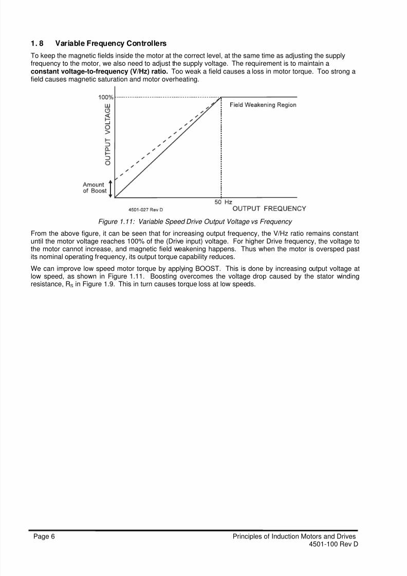
1. 8 Variable Frequency Controllers
To keep the magnetic fields inside the motor at the correct level, at the same time as adjusting the supplyfrequency to the motor, we also need to adjust the supply voltage. The requirement is to maintain aconstant voltage-to-frequency (V/Hz) ratio. Too weak a field causes a loss in motor torque. Too strong afield causes magnetic saturation and motor overheating.
Figure 1.11: Variable Speed Drive Output Voltage vs Frequency
From the above figure, it can be seen that for increasing output frequency, the V/Hz ratio remains constantuntil the motor voltage reaches 100% of the (Drive input) voltage. For higher Drive frequency, the voltage tothe motor cannot increase, and magnetic field weakening happens. Thus when the motor is oversped pastits nominal operating frequency, its output torque capability reduces.
We can improve low speed motor torque by applying BOOST. This is done by increasing output voltage atlow speed, as shown in Figure 1.11. Boosting overcomes the voltage drop caused by the stator windingresistance, RS in Figure 1.9. This in turn causes torque loss at low speeds.
8/13/2019 Principles of VSDs
http://slidepdf.com/reader/full/principles-of-vsds 7/23
Principles of Induction Motors and Drives Page 74501-100 Rev D
CHAPTER 2: PRINCIPLE OF VARIABLE SPEED DRIVE
2.1 Block Diagram of Variable Frequency Drive
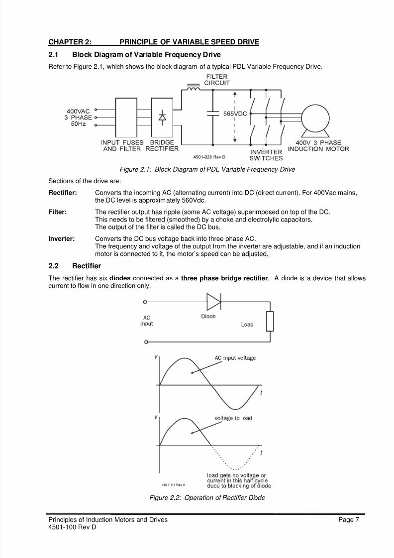
Refer to Figure 2.1, which shows the block diagram of a typical PDL Variable Frequency Drive.
Figure 2.1: Block Diagram of PDL Variable Frequency Drive
Sections of the drive are:
Rectifier: Converts the incoming AC (alternating current) into DC (direct current). For 400Vac mains,the DC level is approximately 560Vdc.
Filter: The rectifier output has ripple (some AC voltage) superimposed on top of the DC.This needs to be filtered (smoothed) by a choke and electrolytic capacitors.The output of the filter is called the DC bus.
Inverter: Converts the DC bus voltage back into three phase AC.The frequency and voltage of the output from the inverter are adjustable, and if an inductionmotor is connected to it, the motor’s speed can be adjusted,
2.2 Rectifier
The rectifier has six diodes connected as a three phase bridge rectifier. A diode is a device that allowscurrent to flow in one direction only.
Figure 2.2: Operation of Rectifier Diode

8/13/2019 Principles of VSDs
http://slidepdf.com/reader/full/principles-of-vsds 8/23
Page 8 Principles of Induction Motors and Drives4501-100 Rev D
Referring to Figure 2.2, on a positive half cycle of the mains, that is, when the top input is more positive thanthe bottom input, the diode is forward biased and will conduct current through the load. On a negative halfcycle, when the top input is more negative than the bottom input, the diode is reverse biased and will blockcurrent from conducting. Thus in the circuit of Figure 2.2, the load will have half of the mains voltage acrossit. Thus if it was a lamp, it would glow with half brightness.
Figure 2.3 shows a full wave three phase rectifier, where six diodes are used to convert AC into DC.
Figure 2.3: Drive Rectifier and Filter Circuit
For a standard 400Vac 50Hz 3 phase mains, the output of the drive’s rectifier is 560Vdc, with some ripplesuperimposed. The ripple is a small AC voltage at a frequency of 300Hz.
UDi/MVi/MFi drives use three diodes and three silicon controlled rectifiers (SCRs) in their rectifier. This hasno effect on the normal operation of the rectifier.
Filter
To get rid of the ripple on the rectifier output, a filter is used. The filter uses two chokes, one in the positiveand one in the negative output of the rectifier.
The filter also uses capacitors. The capacitors are electrolytic, i.e. they are polarised (can only go in thecircuit in one direction) and have a large capacitance (ability to hold charge) for their size. The capacitors weuse are rated at 400Vdc maximum each. Thus to withstand the DC bus voltage, they must be in sets of twoin series. Resistors connected across the capacitors help each series pair of capacitors to share the DC busvoltage between them.
WARNING: The capacitors can hold a lethal charge for some minutes after powerhas been turned off.

8/13/2019 Principles of VSDs
http://slidepdf.com/reader/full/principles-of-vsds 9/23
Principles of Induction Motors and Drives Page 94501-100 Rev D
Soft Charge Circuit
The filter capacitors can draw a lot of current when first charging up. This inrush is noticeable when the driveis first switched on, and can blow fuses or damage the diodes. So a soft charge circuit helps to limit theinrush current to a safe level. The charging current flows through the soft charge resistor When thecapacitors are charged up, the resistor is shorted out by a contactor or relay, and the drive can now be run.
On UDi/MVi/MFi models, soft charging is done by “phase controlling” the rectifier SCRs during this inrush
period.2.3 Inverter Bridge
After smoothing by the filter, the DC voltage is applied to the inverter bridge consisting of six insulated gatebipolar transistors (IGBTs).
Operation of IGBT
In an IGBT, the gate (g) and emitter (e) can be thought of as the control terminals, and the collector (c) andemitter (e) as the power terminals. By placing a voltage between g and e (Vge = 10Vdc) the resistancebetween c and e will go low and switch on any load in the collector circuit. The IGBT can thus act as a powerswitch - it can control high power in its collector circuit with low power in its gate circuit. This is similar to arelay, where low power in its coil will enable high power to be switched through its contacts. The advantagesof an IGBT over a relay are its very fast speed and ease of driving. AN IGBT can switch on a load in 2
microseconds (millionths of a second), compared with a relay taking 10 milliseconds (thousandths of asecond).
Figure 2.4: IGBT Symbol and Operation
Figure 2.5 shows the switching characteristics of an IGBT. Note that there is a finite (although small) time ittakes to switch on and off. The shorter this time, the less the heating of the IGBT due to the switching. Alsonote that when switched on, the voltage across the switch (Vce) does not decrease to zero as would beexpected in an ordinary switch. The lowest Vce goes to is approximately 2.5Vdc. This also causes heating inthe IGBT. Thus the IGBTs need to be mounted on a heatsink, so that the internally generated heating issafely conducted away and does not destroy the IGBT.
Figure 2.5 IGBT Switching Characteristics

8/13/2019 Principles of VSDs
http://slidepdf.com/reader/full/principles-of-vsds 10/23
Page 10 Principles of Induction Motors and Drives4501-100 Rev D
In a PDL Variable Speed Drive inverter bridge, six IGBTs are arranged in a “bridge” configuration. Theswitching of the IGBTs is arranged so that when the top IGBT in each leg (or phase) of the bridge is switchedon, the bottom one is turned off, and vice versa. So if the centre point of each phase (where the motor isconnected to) is observed, it switches periodically to the positive and negative sides of the DC bus.
Figure 2.6: Inverter IGBT Switches and Output Waveforms
If each of the three phases is switched in this manner, but with the switching of each phase delayed by onethird of a cycle behind the previous phase, the three waveforms of the centre point (V AO, VBO, VCO) are asshown in Figure 2.6. The motor sees across its terminals the difference in voltage between any two outputsA, B, C, as shown in the figure as VAB, VBC, VCA. Thus the output of the inverter is a three phase waveform.The output voltage waveform is called a “quasi square-wave” and causes a motor current waveform asshown at the bottom of Figure 2.6.
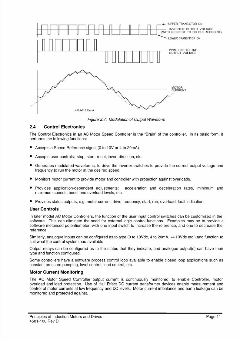
ModulationThe above motor waveform is not very good for the motor because it has a high harmonic content, whichcauses the motor to be noisy and to get too hot. To improve this waveform we modulate the voltagewaveform. This modulation is done to adjust the average output voltage and to make the output currentwaveform look more like a sine wave, which has less harmonics and causes less noise and heating in themotor.
Figure 2.7 shows this modulation technique. The width and number of chops are electronically adjusted tomake the output current closely approximate a sine wave. In this illustration, there are sixteen chops insertedin the cycle. In a practical drive, the number of chops may be 80 per cycle, giving an even smoother motorcurrent waveform.
8/13/2019 Principles of VSDs
http://slidepdf.com/reader/full/principles-of-vsds 11/23
Principles of Induction Motors and Drives Page 114501-100 Rev D
Figure 2.7: Modulation of Output Waveform
2.4 Control Electronics
The Control Electronics in an AC Motor Speed Controller is the “Brain” of the controller. In its basic form, itperforms the following functions:
• Accepts a Speed Reference signal (0 to 10V or 4 to 20mA).
• Accepts user controls: stop, start, reset, invert direction, etc.
• Generates modulated waveforms, to drive the inverter switches to provide the correct output voltage andfrequency to run the motor at the desired speed.
• Monitors motor current to provide motor and controller with protection against overloads.
• Provides application-dependent adjustments: acceleration and deceleration rates, minimum andmaximum speeds, boost and overload levels, etc.
• Provides status outputs, e.g. motor current, drive frequency, start, run, overload, fault indication.
User Controls
In later model AC Motor Controllers, the function of the user input control switches can be customised in thesoftware. This can eliminate the need for external logic control functions. Examples may be to provide asoftware motorised potentiometer, with one input switch to increase the reference, and one to decrease thereference.
Similarly, analogue inputs can be configured as to type (0 to 10Vdc, 4 to 20mA, +/-10Vdc etc.) and function tosuit what the control system has available.
Output relays can be configured as to the status that they indicate, and analogue output(s) can have theirtype and function configured.
Some controllers have a software process control loop available to enable closed loop applications such asconstant pressure pumping, level control, load control, etc.
Motor Current Monitoring
The AC Motor Speed Controller output current is continuously monitored, to enable Controller, motoroverload and load protection. Use of Hall Effect DC current transformer devices enable measurement andcontrol of motor currents at low frequency and DC levels. Motor current imbalance and earth leakage can bemonitored and protected against.

8/13/2019 Principles of VSDs
http://slidepdf.com/reader/full/principles-of-vsds 12/23
Page 12 Principles of Induction Motors and Drives4501-100 Rev D
2.5 220/240Vac Input Drives
Smaller AC Motor Speed Controllers are available for operation off 220/240Vac supplies, either single phaseor three phase. Refer to Figure 2.8 for a block diagram. Single phase input Controllers have single phaserectifiers with four diodes in the rectifier instead of six. For 220/240V Controllers, the DC bus voltage isapproximately 325Vdc and the maximum output voltage is 230Vac 3 phase.
Figure 2.8: Block Diagram of 220/240Vac Input Controller
220/240Vac input Controllers enable operation of small delta-connected motors. Refer to Figure 2.9 fordetails of the necessary winding connections.
Figure 2.9: Winding Connection for 230/400 Vac Motors
2.6 Regeneration and Dynamic Braking
When a motor is driving a high inertia load, then has its output frequency reduced, the motor may be runningfaster than synchronous speed, that is, at negative slip. The same effect may happen when lowering ahoist. Under this condition, the motor is now generating, and is absorbing mechanical energy from the loadback into the Controller. This is called regeneration and is shown in Figure 2.10.
Figure 2.10: Regeneration Region of Induction Motor

8/13/2019 Principles of VSDs
http://slidepdf.com/reader/full/principles-of-vsds 13/23
Principles of Induction Motors and Drives Page 134501-100 Rev D
When regenerating, the energy flows back to the Controller, and is rectified by the transistors’ free-wheelingdiodes, but cannot flow back to the mains because of the one-way input rectifier. The effect of this is to causethe DC Bus to “pump up” in voltage, and this may cause the Drive to trip out if unchecked. A solution is to puta Dynamic Brake across the DC Bus. This is a resistor connected to an electronic voltage-activated switch.Refer to Figure 2.11. When the DC bus voltage exceeds a preset level, the resistor is switched across thebus and dissipates the regenerative energy.
Figure 2.11: Use of Dynamic Brake
2.7 Derating and Types of Load
Up to fulll speed (100% or 50Hz), the torqueavailable from the motor is essentially constant.Above 50Hz, the Controller enters “fieldweakening” where the available torque reduces.
However, at reduced speeds, the inductionmotor’s cooling fan is not as effective. Thus themotor should not be continuously loaded to fulltorque at reduced speeds, unless supplementary
cooling is provided. Refer to Figure 2.12 for anexample of derating.
Figure 2.12: Torque Derating due to Motor Cooling
Figure 2.13: Constant Power Load Figure 2.14: Constant Torque Load
Four basic types of load have been identified, in terms of the load vs speed characteristics. Figure 2.27indicates a constant power load. The torque required by the load increases as the speed decreases, in such
a way that the product of the torque and speed (ie. power) remains constant. Examples are centre drivenwinders and lathes.
Figure 2.28 indicates a constant torque load. In this type of load, the torque require stays constant
regardless of the speed. This is a very common characteristic. Examples are conveyors, hoists andprinting presses. Care must be taken if intending to run for extended periods at low speeds.

8/13/2019 Principles of VSDs
http://slidepdf.com/reader/full/principles-of-vsds 14/23
Page 14 Principles of Induction Motors and Drives4501-100 Rev D
Figure 2.15: Load Proportional to Speed Figure 2.16: Load Proportional to Square of Speed
Figure 2.15 indicates a load where torque is proportional to speed. Such loads include mixers, positive
displacement pumps, compressors etc. Such loads do not normally cause a motor heating problem. Suchloads should not require BOOST to be applied.
Figure 2.16 indicates a load where torque is proportional to the square of the speed. This is a verycommon load type, and applies to centrifugal pumps and fans. Over 70% of loads used on motors controlledby AC Motor Speed Controllers are in this category. The torque required at low speeds is very small.
2.8 Six pole motor in a four pole application
Figure 2.17 4 pole motor Figure 2.18 6 pole motor
The use of a 6 pole motor in a 4 pole application gives better motor cooling and hence a wider useful speed
range. The starting torque is also 50% better.

8/13/2019 Principles of VSDs
http://slidepdf.com/reader/full/principles-of-vsds 15/23
Principles of Induction Motors and Drives Page 154501-100 Rev D
2.9 Full rated torque up to 87Hz
Many small motors can be connected in 230v delta, when this is combined with a 400 volt VSD the field
weakening region is extended to 87Hz (√3 x 50Hz) see figure 2.19. This allows full motor rated torque to be
achieved up to 87hz.
Since Power = 2πRad/Sec x Torque the output power from the motor is increased by √3 at 87Hz with noextra heat generated in the motor because the rated name plate current remains the same.
Example: A 1 Kw 400v star 230v delta motor, is connected in delta at 400v to produce 1.73Kw at
87 Hz.
Star connected motor Delta connected motor
Power = √3x Vline X Iline Power = √3x Vline X Iline
Iline = Power / √3 x Vline Iline = Power / √3 x Vline
Iline = 1 Kw / √3 x 400v Iline = 1.73Kw / √3 x 400v
Iline = 1.4 Amps Iline = 2.5 Amps
Phase current star connected motor Phase current delta connected motor
Iline = Iphase Iline = √3 x Iphase
Iphase = 1.4 Iphase= Iline / √3
Iphase= 2.5 / √3
Iphase= 1.44A
Net heating effect in a motor phase Net heating effect in a motor phase
Power = I2 x RMotor Power = I
2 x RMotor
Power = 1.42x RMotor Power = 1.4
2x RMotor
VSD Output Current Rating VSD Output Current Rating
1.4 Amps 2.5 Amps
Figure 2.19 Field weakening
Frequency
Voltage
Field Weakening at
400v
50 87
400
230
4201-070A
Field Weakening at230v

8/13/2019 Principles of VSDs
http://slidepdf.com/reader/full/principles-of-vsds 16/23
Page 16 Principles of Induction Motors and Drives4501-100 Rev D
CHAPTER 3: PRINCIPLES OF FLUX VECTOR CONTROLLERS
3.1 Difference Between Scalar And Vector Control
As discussed in Section 1, the operation of the three phase induction motor is due to the interaction of the(excited) stator magnetic field with the (induced) rotor magnetic field. The stator excitation produces amagnetic field, which rotates at synchronous speed in the air gap between stator and rotor. This fieldinduces currents in the rotor bars, so giving rise to another rotating magnetic field. These fields want to line
up with each other, so the rotor experiences a torque, and tends to be dragged along with the stator field. Asthe rotor speed approaches that of the rotating stator field, the rotor bar currents will reduce. This reducesthe rotor torque, until when rotating at synchronous speed, the rotor torque is zero. Under normal motoringconditions, the rotor will rotate at a speed slightly slower than that of the stator field. This speed difference istermed the slip, and the more slip, the more torque the motor will deliver to the load.
By applying a variable voltage variable frequency (VVVF) controller, as discussed in Section 2, the stator fieldrotation speed can be changed, thus the rotor speed changes. This is done. For most motor speed controlapplications, e.g. pumps, fans, conveyors, etc., this is a satisfactory method of speed control. However thereare some types of load where the performance of a VVVF controller is not good enough for operating theinduction motor. One such application area is where very fast speed response is needed, e.g. in positioncontrol systems and flying shears. Under such highly dynamic conditions, the operation of a VVVF controllerwill be underdamped or even unstable. Another area where a VVVF controller is not particularly suitable is intorque control applications, e.g. rewinders, torque boosters, etc. Also the standstill torque and low speedtorque capabilities of a VVVF controller on an induction motor are not very good, making it unsuitable for useon hoists and elevators.
For high performance operation, closed loop torque control is required. This requires that the torqueproducing and magnetising components of stator current must be accurately and separately controlled asvectors, i.e. they are controlled in both magnitude and spatial position. The two components are kept inquadrature, i.e. 90
O electrical apart. This class of induction motor controller is referred to as a FieldOrientated Flux Vector Controller, or simply Vector Controller, as represented by the PDL Microvectorrange. This type of controller has very fast torque response, making it suitable for precision torque, speedand position control applications. The ability to get up to full pull-out torque of the motor at all speeds,including standstill, makes this controller suitable for cranes, hoists and elevators.
3.2 Review of Basic Motor Principles
Figure 3.1: Force on Current-carrying Conductor in a Magnetic Field
All electric motors work on a basic principle of electromagnetism. According to this principle, when anelectric current is passed through a conductor that is in a magnetic field, a force acts on the conductor. Thisis shown in Figure 3.1. If the current-carrying conductor is at right angles to the field, then the magnitude ofthe force can be calculated from the equation
F = B x i x L
where F = force in Newtons, B = magnetic flux density in Teslas, L = conductor length in metres.

8/13/2019 Principles of VSDs
http://slidepdf.com/reader/full/principles-of-vsds 17/23
Principles of Induction Motors and Drives Page 174501-100 Rev D
The direction of the force can be deduced from the left-hand motor rule. Extend the thumb, forefinger andmiddle finger of the left hand so they are mutually perpendicular. If the forefinger represents the direction ofthe magnetic flux lines, and the middle finger the direction of (conventional) current flow, then the thumbpoints in the direction that the conductor is pushed. Control of the torque output of a motor is by control ofthe above forces on the rotor conductors, by controlling either the field strength (B) or the rotor current (i).
In a separately excited DC motor, torque control is comparatively straightforward, as discussed in Section3.3. However in an AC induction motor, the rotor conductor current is achieved by induction, that is, by the
stator field B cutting past the rotor conductors at slip speed and generating currents in the rotor bars. Thusthe same current forced into the stator windings gives rise to the motor flux (B) and induces the rotor current(i). Thus to control the torque output of an AC induction motor, we need to control the instantaneousmagnitude and phase of the three-phase stator currents to enable direct and independent control of B and I.This is called Field Orientated Flux Vector Control.
3.3 Review of DC Motor
The separately excited DC motor, as shown in Figure 3.2, is an example of a vector controlled motor. Thearmature (torque producing) current is kept in quadrature (at right angles) to the field producing current by thecommutator and brushgear. The field flux is directly proportional to the field current, and can be controlledindependently of the armature current. The shaft torque is proportional to the product of the field flux andarmature current. If the field current is kept constant, the motor output torque can be controlled by controllingarmature current. Response to a step change in armature current is fast and well damped.
Figure 3.2: Separately Excited DC Motor However DC motors have many disadvantages when compared to squirrel cage induction motors. Theirbrushes and armatures make them high maintenance motors. The armature windings are complicated andrewinding is expensive. The motors normally have a poor ingress protection (IP) rating, and brushgear arcingprevents their use in any hazardous area. The induction motor, by comparison, is much simpler inconstruction, and is available in waterproof, submersible, or flameproof formats. It is generally moremechanically rugged, and much less expensive than its DC counterpart.
3.4 Concepts of Induction Motor Vector Control
Figure 3.3: Steady-state Equivalent Circuit of Induction Motor
Figure 3.3 shows the equivalent circuit of a phase of an induction motor. Circuit parameters are as follows:Lls = stator leakage inductance - due to imperfect magnetic coupling between adjacent turns
Rs = stator winding resistance - due to resistance of copper wire - cause of stator losses
Lm = stator magnetising inductance - gives rise to rotating stator field
Llr = rotor leakage inductance
Rr = rotor resistanceRr (1-s)/s = equivalent load resistance - changes with motor slip

8/13/2019 Principles of VSDs
http://slidepdf.com/reader/full/principles-of-vsds 18/23
Page 18 Principles of Induction Motors and Drives4501-100 Rev D
There are two components of current into the motor:IM(t) magnetising current, i.e. flux producing current. This current is mainly imaginary,
i.e. inductive. A small real, i.e. resistive, current component flows, due to iron lossesin the stator.
IR(t) load current, i.e. torque producing current. This component is mainly real,
i.e. resistive or work-producing current. A small imaginary, i.e. inductive, currentflows, due to rotor and stator leakage inductances.
The produced torque can be expressed as:
T = Ka x IM(t) x IR(t) x sin α
It must be remembered that these two quantities are alternating, having the same frequency but not
necessarily in quadrature. The phase difference α between the two currents will vary from 90O due to the
effects of the leakage inductances. This variance will be worse at low speeds and under heavy loads.
In a AC induction motor, the same current forced into the three phase stator windings gives rise to themagnetising (air gap) flux (B) and induces the torque producing (rotor) current (i). It is not possible toseparately and independently access these two quantities. The main function of the Vector Controller is toovercome this problem by maintaining a quadrature relationship between magnetising and torque producingcomponents of the stator current, and decoupling the components in such a way that each can beindependently controlled, even under highly dynamic conditions.
Vector control needs to have a feedback from the motor of the magnitude and orientation of the air gap flux.This then enables the two current components to be controlled. Early Vector Controllers employed directvector control, by using flux sensors in the air gap to produce the required signals. However this required aspecial motor and did not achieve acceptance. Later controllers employ indirect vector control, where themagnitude and orientation of air gap flux is computed from a knowledge of the motor’s parameters (called themotor map), and the instantaneous relative rotor position, measured using an incremental shaft encoderdriven by the rotor. Complex and tedious calculations have to be carried out on-line and at high speed inorder to achieve fast response. This has only been practical since the advent of fast and powerfulmicroprocessors. The PDL Microvector is an example of a modern indirect Vector Controller.
3.5 Concept of Rotating Reference Frame
In the induction motor, the air gap flux rotates at synchronous speed. The rotor current and therefore rotor
flux induced by this air gap flux travels past the rotor at slip speed. Thus the relative angular position of rotorflux is stationary with respect to the stator flux. Thus we can use a synchronously rotating reference frame asa reference co-ordinate system. With respect to this reference frame, both the rotor and stator fluxes arestationary and their mutual interaction produces torque. To achieve this rotating reference frame, amathematical transformation is required between a three phase stationary reference frame and a two phaserotating reference frame with d and q axes. This is shown in Figure 3.4.
Figure 3.4: Vector Diagram of Stator Current Components Relative to Rotating Reference Frame
In this rotating reference frame, variables like voltages and currents are purely real currents (like DCquantities) without modulation. In this frame, the RMS values of IM(t) and IR(t) transform to Id and Iq. Thusour torque equation can be re-written:
T = ka x I
d x I
q
The analogy to the DC motor is Id corresponds to field current If, and Iq corresponds to armature (torqueproducing) current Ia.
8/13/2019 Principles of VSDs
http://slidepdf.com/reader/full/principles-of-vsds 19/23
Principles of Induction Motors and Drives Page 194501-100 Rev D
3.6 Synthesis of Stator Current
Referring to Figure 3.4, when the Vector Controller is operating below base speed, the magnitude of I d isfixed. The required magnitude of Iq can then be computed, based on the reference (required) torque. Fromthese values, the magnitude of the required stator current can be calculated:
Is = √(Id2 + Iq2)
Iq is a function of the slip of the rotor. The required slip frequency (in radians/sec) can be calculated from:
ωs = Iq / (Tr x Id )
where Tr = rotor coupled time constant, ie., Lr / Rr, which depends on the motor design.
This required slip speed can then be used to calculate the required instantaneous phase of the stator current,
by integrating rotor speed (ωr) and generated slip (ωs). Once again, referring to Figure 3.4:
ϕ = ∫ (ωr + ωs)dt + θ
where θ = tan-1 (Iq / Id)
By combining the above equations, the instantaneous stator current magnitude and phase angle can becalculated. The accuracy of the calculations is dependent on the accuracy of the motor and shaft encoderparameters programmed into the Vector Controller, thus correct "tuning" of the controller is very important ifgood performance is required.
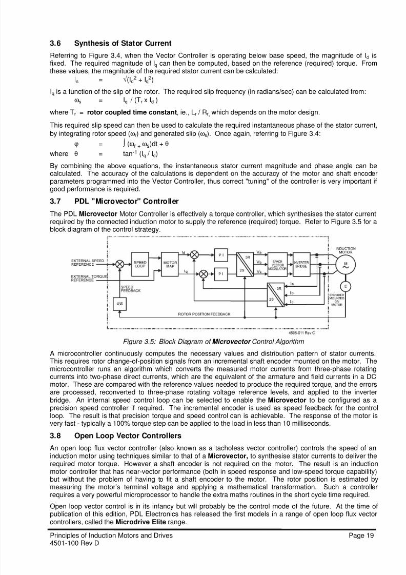
3.7 PDL "Microvector" ControllerThe PDL Microvector Motor Controller is effectively a torque controller, which synthesises the stator currentrequired by the connected induction motor to supply the reference (required) torque. Refer to Figure 3.5 for ablock diagram of the control strategy.
Figure 3.5: Block Diagram of Microvector Control Algorithm
A microcontroller continuously computes the necessary values and distribution pattern of stator currents.This requires rotor change-of-position signals from an incremental shaft encoder mounted on the motor. Themicrocontroller runs an algorithm which converts the measured motor currents from three-phase rotatingcurrents into two-phase direct currents, which are the equivalent of the armature and field currents in a DCmotor. These are compared with the reference values needed to produce the required torque, and the errorsare processed, reconverted to three-phase rotating voltage reference levels, and applied to the inverter
bridge. An internal speed control loop can be selected to enable the Microvector to be configured as aprecision speed controller if required. The incremental encoder is used as speed feedback for the controlloop. The result is that precision torque and speed control can is achievable. The response of the motor isvery fast - typically a 100% torque step can be applied to the load in less than 10 milliseconds.
3.8 Open Loop Vector Controllers
An open loop flux vector controller (also known as a tacholess vector controller) controls the speed of aninduction motor using techniques similar to that of a Microvector, to synthesise stator currents to deliver therequired motor torque. However a shaft encoder is not required on the motor. The result is an inductionmotor controller that has near-vector performance (both in speed response and low-speed torque capability)but without the problem of having to fit a shaft encoder to the motor. The rotor position is estimated bymeasuring the motor’s terminal voltage and applying a mathematical transformation. Such a controllerrequires a very powerful microprocessor to handle the extra maths routines in the short cycle time required.
Open loop vector control is in its infancy but will probably be the control mode of the future. At the time ofpublication of this edition, PDL Electronics has released the first models in a range of open loop flux vectorcontrollers, called the Microdrive Elite range.

8/13/2019 Principles of VSDs
http://slidepdf.com/reader/full/principles-of-vsds 20/23
Page 20 Principles of Induction Motors and Drives4501-100 Rev D
CHAPTER 4 PRINCIPLES OF REDUCED VOLTAGE STARTERS
4.1 DIRECT-ON-LINE STARTING
The direct-on-line starting characteristics of an induction motor can be better understood by studying the fullequivalent circuit of the motor. Refer to Figure 4.1.
Figure 4.1: Full Equivalent Circuit of One Phase of Induction Motor
Figure 4.1 represents the steady-state equivalent circuit of one phase of an induction motor. Circuitparameters are as follows:
Lls = stator leakage inductance - due to imperfect magnetic coupling between adjacentstator turns
Rs = stator winding resistance - due to resistance of copper wire - cause of stator losses
Lm = stator magnetising inductance - gives rise to rotating stator field
Llr = rotor leakage inductanceRr = rotor resistance
Rr (1-s)/s = RL = equivalent load resistance - changes with motor slip
On start up, slip is at a maximum (1.0) and RL becomes very small, and appears as a short circuit. The statorcurrent on starting virtually all flows to the rotor and its magnitude is only limited by the stator and rotorreactances (RS, LlS, Rr, Llr). Also voltage divider effects between stator and rotor reactances will ensure thatLm does not get full input voltage supplied. Thus at start up, the field in the motor is weakened and themotor’s torque reduced to approximately 50% of peak.
Refer to Figures 4.2, 4.3 for typical Torque vs Speed and Current vs Speed curves for squirrel cage motors.
Figure 4.2: Torque vs Speed Curve Figure 4.3: Current vs Speed Curve
4.2 Problems With Direct-On-Line Starting
On starting an induction motor direct-on-line, (DOL), three effects are noticeable.
The first effect is the large amount of excess torque available. Refer to Figure 4.2. Even though the startingtorque is reduced, the torque does jump quickly to peak value as the rotor speed increases. This torque canbe far in excess of what the load requires, as shown in the figure. This excess torque is represented by thearea above the load torque requirement curve and below the motor torque curve. When DOL starting, thisexcess torque can cause mechanical shock, belt slippage, and stress in transmission components. It can
cause water hammer in pipes connected to motor-driven pumps. DOL starting is essentially an uncontrolledstart.

8/13/2019 Principles of VSDs
http://slidepdf.com/reader/full/principles-of-vsds 21/23
Principles of Induction Motors and Drives Page 214501-100 Rev D
The second effect is the large starting current drawn by the motor, as illustrated in Figure 4.3. This startingcurrent is typically, at the instant of starting, six times full load current. It is because at start-up, the motor hasfull slip, and looks like a transformer with a shorted secondary (rotor). This high current can causeconsiderable voltage sags on a low capacity mains supply, and necessitates the rating of all induction motorswitchgear and fusegear to handle this surge without damage. Local electricity distribution authorities usuallyinsist that measures are taken to reduce this starting surge.
The third effect is to cause additional heating in the motor. Rotor heating is made worse because the rotor
usually has a higher effective resistance on starting compared with when running, because of the "skin effect"caused by the high slip frequency on the rotor. Overheating of the rotor can be severe with repeated starts,or with high load inertias or torques, and can cause rotor shorting ring failure or rotor cage melt-down.
4.3 Effect of Reduced Starting Voltage
It can be shown that if the starting voltage supplied to an induction motor is reduced, the torque availablefrom the motor reduces as the square of the voltage reduction. Refer to Figure 4.4. If the input voltage tothe motor is reduced to 71%, then the torque available is reduced to 50% (0.71 x 0.71) of its full value. Thestart current is also reduced, but not to the same extent as the torque.Any reduced voltage starting technique will cause the motor to operate at high slip for longer periods duringstart up. At high slip, the torque is only moderate, power factor is poor and rotor heating is very high.
Figure 4.4: Torque vs Speed Curves as Function of Voltage
A variable frequency drive is a most effective way of starting any induction motor. Because the drive isincreasing the frequency at a controlled rate, the motor can be brought up to speed without incurring largeslip, thus the starting current can be minimised and starting torque controlled. Also, once started, the motor’sspeed can be continuously varied. The main disadvantage is the higher initial cost of such a drive.
A cheaper option is to run the motor from an electronic reduced voltage starter (RVS). This supplies themotor from 3-phase mains, via a phase-controlled SCR stack. The triggering or gating of the SCRs can becontrolled to control starting voltage or to limit starting current.
4.5 Principles of SCR Phase Control
An SCR (silicon controlled rectifier, or thyristor) is a semiconductor switching device, with two powerterminals, called the anode (A) and cathode (K) and one control terminal called the gate (G).
Operating Principles: Refer to Figure 4.5.
If terminal K (cathode) is taken positive with respect to A, the SCR is reverse biased and will block currentfrom flowing.
If terminal A is taken positive with respect to K, the SCR is forward biased, and will block current flow untilterminal G (the gate) receives a positive pulse with respect to K. This trigger pulse will trigger the SCR intoconduction and current will pass from A to K. The SCR will continue to conduct after the trigger pulse hasceased, until current through the SCR ceases, at which point it returns to a blocking state.

8/13/2019 Principles of VSDs
http://slidepdf.com/reader/full/principles-of-vsds 22/23
Page 22 Principles of Induction Motors and Drives4501-100 Rev D
Figure 4.5: Silicon Controlled Rectifier (SCR) Symbol and Characteristics
Inverse Parallel Connection:
If two SCRs are connected in parallel, anodes tocathodes as shown in Figure 4.6, this is called aninverse parallel connection, (also calledantiparallel). In this configuration, the SCRs canbe used to control AC waveforms. On positive halfcycles, SCR1 controls the current flow to the load.
On negative half cycles, SCR2 controls the currentflow. Figure 4.6: SCRs in Inverse Parallel Connection
Phase Control:
If the SCRs are connected in inverse parallel, and the triggering pulse for each SCR is at a controlled point ineach half cycle of the AC. waveform, we have the means to control the average voltage applied to the load.Refer to Figure 4.7. This depicts the voltage appearing across the load in response to the adjustment of thefiring point of the SCRs in each half cycle.
Figure 4.7(a) shows the voltage on the load when the SCRs are triggered (fired) late in each half cycle. Theaverage voltage on the load (represented by the black portion of the waveform) is comparatively low.Figure 4.7(b) shows the load voltage when the SCRs are triggered half way through each half cycle. Theaverage load voltage is now 50% of the input voltage.Figure 4.7(c) shows the load voltage when the SCRs are triggered early in each half cycle. The average loadvoltage is approximately 80% of the input voltage.
This method of controlling the load voltage by controlling the triggering points of the SCRs is called phasecontrol, and is the principle behind PDL Electronics’ Reduced Voltage Starters.
Figure 4.7: Phase Control of AC Waveform
4.6 Configuration of Electronic Reduced Voltage Starters
Refer to Figure 4.8.
The PDL Electronic Reduced Voltage Starter has three pairs of inverse parallel SCRs, one pair in each linebetween the three phase supply and the three phase motor.
These SCRs are phase controlled with the firing pulses generated by a Control Electronics PCB. These firingpulses are directed to each of the six SCRs by a pulse transformer or opto-coupler, to give galvanic isolationbetween the Control Electronics and power circuits. Thus the motor can be started and stopped, and thevoltage to the motor can be controlled automatically, via the Control Electronics PCB.
More sophisticated reduced Voltage Starters (eg. PDL’s RVSi range) measure the current flowing to the
motor, and can control this current and provide motor thermal overload protection. Input fuses are providedto protect the SCRs and motor against overloads and short circuits.

8/13/2019 Principles of VSDs
http://slidepdf.com/reader/full/principles-of-vsds 23/23
Figure 4.8: Electronic Reduced Voltage Starter Circuit Configuration
4.7 Voltage Ramp Starting, Current Limit Starting
Voltage ramp starting is a starting method whichapplies a steadily increasing voltage to the motor.Refer to Figure 4.9(a). In this example the outputvoltage of the starter is ramped from 0 to 100% infour seconds. However it should be noted thatthere is a time delay between the ramp startingand the motor starting to rotate. The ramp time isuser adjustable. Normally a user adjustable "StartVolts" level is applied. This causes the ramp tostart at a preset level, and ramp up from there. Inthe example in Figure 4.9(b), this "Start Volts"level is set to 40%. This ensures that the motorstarts turning immediately on start-up, but without"grabbing".
Figure 4.9: Voltage Ramp Starting
In Current Limited Starting, the maximumrequired start current is preset by the user. Whenstarted, the Reduced Voltage starter will ramp upat the preset ramp rate until motor current reachesthe preset level. At this point the output voltageramp is automatically adjusted to hold the startingcurrent at or below this level. This method is
suitable if the maximum start current is to belimited due to, for example, inadequate mainscapacity, or for starting high inertia loads whichare loaded up only when they reach full speed, eg.fans, saw blades, etc.
Figure 4.10: Current Limited Starting
In Figure 4.10(a), a current limit of 400% has been set, and the load accelerates to full speed successfully.However in Figure 4.10(b), the current limit has been set down to 200%, and at a point in the start cycle, thetorque required by the load exceeds the torque available from the motor. The motor will not acceleratebeyond this point, and will enter a "rolling stall".
The motor will continue to draw twice full load current, and because of its reduced speed will have reducedcooling. Thus the motor will overheat very quickly. This illustrates the danger of setting too low a current limitlevel.