prisma ipm brochure
TRANSCRIPT

Prisma iPMLow Voltage Distribution System
IEC 61439 - 1 & 2
se.com
Certified assembly as per
SINCE 1998
SAMCON Prisma Partner

Improve the continuity of service
Ensure the safety of life and property
Control deadlines and costs
Innovate with
> An innovative solution based on theexperience, expertise and switchgearofferings from the global specialist inenergy management.
Prisma iPM solution
Prisma iPM
Using our Prisma iPM solution, you can easily
design, implement and operate LV electrical
distribution switchboard that are dependable,
because they are optimised, tested, compliant
and certified as per IEC 61439-1 & 2 standards.
SINCE 1998

For all applications
up to 4000 ACommercial and industrial
buildings, hotels, hospitals etc.:
a Prisma iPM switchboard can
be installed anywhere!
= Floor standing cubicle range= Wall mounted enclosure ranges= IP degree: from 30 to 54= Icw: from 15 kA/s to 85kA/s= Partitioning up to form 4b
SINCE 1998

Presentation
IEC 61439 standard
The switchboard,central to the electricalinstallationThe IEC 61439 standard aims to better define ‘‘low-voltage switchgear and controlgear assemblies’’,
ensuring that the specified performances are reached. It specifies in particular:> the responsibilities of each player, distinguishing those of the original equipment manufacturer; the
organization that performed the original design and associated verification of an assembly in accordance
with the standard, and of the assembly manufacturer -the organization taking responsibility for the finished
assembly;> the design and verification rules, constituting a benchmark for product certification.All the component parts of the electrical switchboard are concerned by the IEC 61439-2 standard.
Equipment produced in accordance with the requirements of this switchboard standard ensures the safety
and reliability of the installation.
> Specify switchboards that comply with standard IEC 61439-1 and 2.> guarantee a level of safety that has been 100% tested, from the day the switchboard is installed and
throughout its service life.> ensure a lasting investment through easy upgrading of the installation in compliance with the
standard.> guarantee that the switchboard complies with the technical specifications.
The conformity of the switchboard has been tested and proven.A Prisma iPM switchboard is:> made up of Schneider Electric low-voltage devices and components that all comply with the applicable
standards;> based on configurations in our catalogue;> made up of Prisma iPM mechanical and electrical components that have been subjected to the verification
of original equipment manufacturer;> mounted and wired by a panelbuilder in compliance with professional standards;> subjected to the individual verification. Schneider Electric makes available to the panelbuilder everything
required to create tested Prisma iPM switchboards, including the basic configurations in the low voltage
distribution catalogue, all the ocumentation for switchboard design and mounting, calculation and design
software, etc. Panelbuilders can demonstrate conformity with standard IEC 61439-1 and 2 by presenting the
declarations or certificates of conformity for type tests carried out by ndependent laboratories (ASEFA,
ASTA, KEMA, etc.) and supplied by Schneider Electric. The panelbuilder is responsible for the individual
routine verification and delivers the corresponding declarations of conformity.
Prisma iPM tested switchboards
The Schneider Electric solution
SINCE 1998

Safety
Continuity of service
Compliance with end-user requirements
Presentation
IEC 61439 standard
The main 10 functions of standard IEC 61439For each of the following 10 functions, the standard IEC 61439 requires design verifications from the system manufacturer - mainly through type-tests - and routineverifications on each panel from the Panel Builder to achieve 3 basic goals: safety, continuity of service and compliance with end-user requirements.
Voltage stresses withstand capabilityTo withstand long term voltages, and transient and temporary overvoltages according to the insulation coordinationprinciples and requirements.Current-carrying capabilityTo protect against burns and to withstand temperature rise:> when any circuit is continuously loaded, alone, to the specified current> when the assembly is loaded to the specified current according to the specified load pattern (between circuits and/or asa function of the time).Short-circuit withstand capabilityTo withstand the stresses resulting from the prospective short-circuit current and from the associated data (High forces between conductors, temp. rise in a very short time, air ionization, overpressure).Protection against electric shock> Hazardous-live-parts not to be accessible (basic protection)> Accessible conductive parts not to become hazardous-live (fault protection).Protection against risk of fire or explosion> Resistance to internal glowing elements> Note: Protection of persons, and optional protection of the assembly, against arcing due to internal fault can be specified through a ‘‘special test’’ according to IEC 61641.
Maintenance and modification capabilityCapability to preserve continuity of supply without impairing safety during assembly maintenance or modification> Electrical condition of the assembly or various circuits> Speed of exchange of the functional units> Test facilities…Electro-Magnetic compatibilityTo properly function (immunity) and not to generate EM disturbances (emission) in specified environmental conditions:> Industrial networks or locations (Environment A)> Domestic, commercial, and light industrial locations (Environment B).
Capability to operate the electrical installationTo properly function, according to:> The electrical diagram of the overall system and related information (voltages, coordination…)> The specified operating facilities (e.g. free or restricted access to Man Machine Interfaces, isolation of the outgoing circuits, …).Capability to be installed on site> To withstand handling, transport, storage… and installation constraints> Capability to be erected and connected (type of enclosure, type, material and cross sectional areas of externalconductors).Protection of the assembly against mechanical and atmospheric environmental conditions> Presence of water or solid foreign bodies (IP according to IEC 60529)> External mechanical impacts (optional IK according to IEC 62262)> Indoor or outdoor installation (humidity, UV).
SINCE 1998

Prisma iPM... 100% and more than
Functional panels for tertiary and industrial buildings
Short-circuit withstand capability
Protection against electrical shock
Voltage stress withstand capability
= Conditional short-circuit test is passed thanks to full coordination using Schneider Electric’s devices associated with Prisma iPM distribution components from incoming to outgoers stages= This panel design characteristic allows a much improved service continuity of the switchboard in case of electrical fault.
= IPxxB Prisma iPM offers standard componentsto achieve the right level of electrical protection.= Terminal block covers= Terminal shields for devices= Partitioning for busbar and connections.
= Creepage distances and clearance distances:all functional units are designed from an earlyengineering stage taking into account minimumclearance distance for any type of assembly ofSchneider Electric devices configuration.For instance the Compact NSX breaker can beinstalled with a rotary handle or motor control orplugiin base with guaranteed clearance distances.= For creeping distances all busbar supports aredesigned to take into account minimum creepagedistances required by the IEC standard.
SINCE 1998

Linergy busbar
Capability to operate the electrical installation
Capability to be installed on site
IEC stadard
Maintenance and modificationcapability
= Beyond IPxxB for pane accessibility Prisma iPMfunctional system has been designed to offer a clear and logical electrical organisation. It enables safer and more secure accessibility for maintenance and upgrades.= Interventions are made quicker with reduced risks of mistakes therefore decreasing down time and improving service continuity.
= Linergy busbar can safely be accessedfor installation upgrade by removing a single Form 2 front barrier only.= All conductors are shifted 25mm enabling qualified electricians to perform intervention from the front of the cubicle only no need to dismantle the side partitioning for access.= Upgrade or maintenance interventions are made faster and more straight forward.
= Prisma iPM components are designedto match Schneider Electric’s devices withimpulse voltage withstand reaching up to12.8kV specification.= Customers are guaranteed to have the right safety margin in case of network transients, increasing safety and installation service continuity over time.
= In addition to being lift-tested, Prisma iPMalso features handling plinths in order to cover all possibilities for site installations where lifting space is too limited.
SINCE 1998
2
3
1
5
4
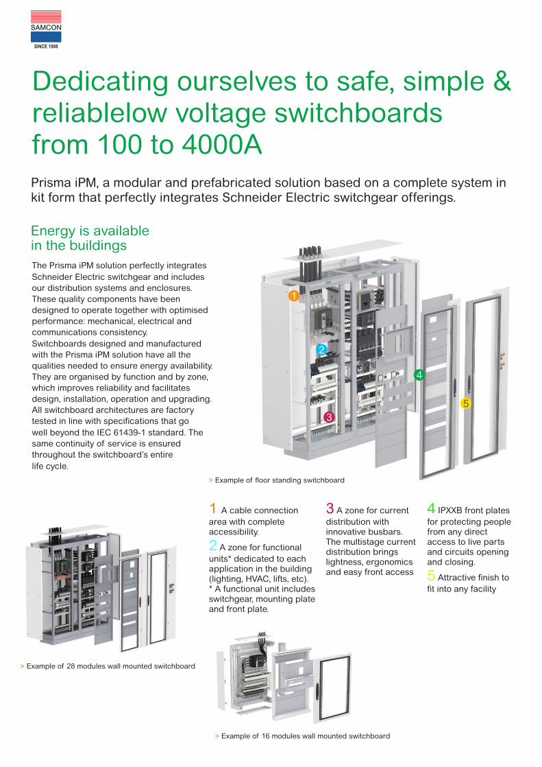
Energy is available in the buildings
1
2
3
4
5
Dedicating ourselves to safe, simple & reliablelow voltage switchboardsfrom 100 to 4000APrisma iPM, a modular and prefabricated solution based on a complete system in kit form that perfectly integrates Schneider Electric switchgear offerings.
The Prisma iPM solution perfectly integrates
Schneider Electric switchgear and includes
our distribution systems and enclosures.
These quality components have been
designed to operate together with optimised
performance: mechanical, electrical and
communications consistency.
Switchboards designed and manufactured
with the Prisma iPM solution have all the
qualities needed to ensure energy availability.
They are organised by function and by zone,
which improves reliability and facilitates
design, installation, operation and upgrading.
All switchboard architectures are factory
tested in line with specifications that go
well beyond the IEC 61439-1 standard. The
same continuity of service is ensured
throughout the switchboard’s entire
life cycle.
> Example of floor standing switchboard
1 A cable connection
area with completeaccessibility.
A zone for functional2
units* dedicated to eachapplication in the building(lighting, HVAC, lifts, etc).* A functional unit includesswitchgear, mounting plateand front plate.
3 A zone for current
distribution with innovative busbars. The multistage current distribution bringslightness, ergonomics and easy front access
4 IPXXB front plates
for protecting people from any direct access to live parts and circuits opening and closing.
Attractive finish to 5
fit into any facility
> Example of 28 modules wall mounted switchboard
> Example of 16 modules wall mounted switchboard
SINCE 1998

Technical data
Floor standing enclosures
A lcw IP IK No. of mod. height width depth associability
Cu upto 4000 Aupto 85 kA
rms/1s30/31/40/54
07
36 2000 mm
300 mm 400 mm width
width
08 400 mm 600 mm
Wall mounted enclosure
A lcw lpk IP IK No. of mod. height width depth associability
Full kits 630 A 25 kA 53 kA 30/31/40/ 07/08/ 4 300 mm 600 mm (enclosure) 235 mm width and
rms/1s 41/54 10 6 500 mm 300 mm (cable duct) 235 mm height
12 700 mm 235 mm
16 900 mm 235 mm
20 1100 mm 235 mm
24 1300 mm 235 mm
28 1600 mm 600 mm (enclosure) 305 mm width
32 1800 mm 300 mm (cable duct) 305 mm
Enclosures 630 A 25 kA 53 kA 30/40/41 07/08 4 700 mm 600 mm 235 mm
(partial kit) rms/1s 8 900 mm
12 1100 mm
16 1300 mm
20
24
28
32
The Prisma iPM solution perfectly incorporates Schneider Electric switchgear:
> Easypact MVS
> Easypact CVS
> Masterpact NW
> Masterpact MTZ
> Acti 9
> GV2L
> LC1 contactors
> LRD thermal relay
> ATV 61/71
> ATS 48C/48D
> Compact NS
> Compact NSX
Al upto 3600 Aupto 65 kA
rms/1s42/54 10
10
600 mm
400 mm
300 mm
1000 mm
600 mm
1000 mm
800 mm
600 + 300 mm
1200 mm
1600 mm
800 mm
600 mm
600 + 200 mm
800 mm
2000 mm36
SINCE 1998

Schneider Electric India Pvt. Ltd.Corporate Office
9th Floor, DLF Building No.10, Tower C, DLF Cyber City,
Phase II, Gurgaon - 122002, Haryana.
Phone: 0124 3940400, Fax: 0124 4222036
www.se.com
Customer Care Centre
Toll-free numbers: 1800 103 0011, 1800 419 4272
General number: 0124 4222040
Email: [email protected]
Unit No. 112, Krishna Building, Laxmi Industrial Complex, Pokhran Road. No. 1, Vartak Nagar, Thane (West) - 400 606. INDIA.Telephone : +91 22 2585 6701, 75063 55683Telefax : +91 22 2588 8451 Email: [email protected] | [email protected] [email protected] www.samconcontrolpanel.com www.samconcontrolpanels.com
SINCE 1998 CIN No. : U31200MH1998PTC114659
ISO 9001 - 2015 | ISO 14001 - 2015 | OHSAS 18001 - 2007 Certified
SAMCON INDUSTRIAL CONTROLS PVT. LTD.