pro pelvis and acetabulum systemaz621074.vo.msecnd.net/syk-mobile-content-cdn/global-content... ·...
TRANSCRIPT
PRO Pelvis and
Acetabulum SystemOperative technique

PRO | Operative technique
2
Contents
Introduction . . . . . . . . . . . . . . . . . . . . . . . . . . . . . . . . . 4
Indications and contraindications . . . . . . . . . . . . . . . . 5
PRO system design – implants . . . . . . . . . . . . . . . . . . . 6
Design summary . . . . . . . . . . . . . . . . . . . . . . . . . . . 6
Matta pelvic plates . . . . . . . . . . . . . . . . . . . . . . . . . . 6
PRO quadrilateral surface plates . . . . . . . . . . . . . . 8
Matta pelvic system screws . . . . . . . . . . . . . . . . . . 10
PRO system design – instruments . . . . . . . . . . . . . . . 11
PRO system design – trays . . . . . . . . . . . . . . . . . . . . . 15
Retractors . . . . . . . . . . . . . . . . . . . . . . . . . . . . . . . . . . 16
PRO carbon fiber retractors . . . . . . . . . . . . . . . . . . 16
Matta sciatic nerve retractors . . . . . . . . . . . . . . . 18
PRO retractor 1 . . . . . . . . . . . . . . . . . . . . . . . . . . . . 18
PRO retractor 2 . . . . . . . . . . . . . . . . . . . . . . . . . . . . 19
PRO retractor 3 . . . . . . . . . . . . . . . . . . . . . . . . . . . . 19
PRO suction retractor . . . . . . . . . . . . . . . . . . . . . . 19
Reduction instruments . . . . . . . . . . . . . . . . . . . . . . . . 20
Ball spike pushers . . . . . . . . . . . . . . . . . . . . . . . . . 20
PRO reduction instruments . . . . . . . . . . . . . . . . . 21
PRO jaw clamps . . . . . . . . . . . . . . . . . . . . . . . . . 22
PRO Weber clamps . . . . . . . . . . . . . . . . . . . . . . 24
PRO Jungbluth clamps . . . . . . . . . . . . . . . . . . . 25
PRO Farabeuf clamps . . . . . . . . . . . . . . . . . . . . 26
Additional Matta reduction clamps . . . . . . . . . 27
Screw fixation . . . . . . . . . . . . . . . . . . . . . . . . . . . . . . . 28
Spiked screw inserter . . . . . . . . . . . . . . . . . . . . . . 28
Swiveling spiked disk . . . . . . . . . . . . . . . . . . . . 28
Washer loading stand . . . . . . . . . . . . . . . . . . . . 28
Pelvic and acetabular fractureOperative technique
PRO | Operative technique
3
Plate contouring and bending techniques . . . . . . . . 30
PRO plate bender . . . . . . . . . . . . . . . . . . . . . . . . . . .31
PRO plate bending holder . . . . . . . . . . . . . . . . . . . 32
PRO in-situ bender . . . . . . . . . . . . . . . . . . . . . . . . 32
Plate and screw fixation . . . . . . . . . . . . . . . . . . . . . . . 33
Handle for plate insertion . . . . . . . . . . . . . . . . . . 33
Plate screw inserter . . . . . . . . . . . . . . . . . . . . . . . 33
Angled depth gauge . . . . . . . . . . . . . . . . . . . . . . . . 33
Pelvic ring fracture types and fixation . . . . . . . . . . . 34
Pubic symphysis disruption . . . . . . . . . . . . . . . . . 34
Ilium fracture . . . . . . . . . . . . . . . . . . . . . . . . . . . . 34
Sacroiliac dislocation . . . . . . . . . . . . . . . . . . . . . . 35
Sacroiliac fracture / dislocation . . . . . . . . . . . . . . 35
Sacrum fracture . . . . . . . . . . . . . . . . . . . . . . . . . . 36
Acetabular fracture types and fixation . . . . . . . . . . . 37
Posterior wall . . . . . . . . . . . . . . . . . . . . . . . . . . . . 37
Posterior column . . . . . . . . . . . . . . . . . . . . . . . . . . 37
Anterior wall . . . . . . . . . . . . . . . . . . . . . . . . . . . . . 38
Anterior column . . . . . . . . . . . . . . . . . . . . . . . . . . 38
Transverse . . . . . . . . . . . . . . . . . . . . . . . . . . . . . . . 39
T-shaped . . . . . . . . . . . . . . . . . . . . . . . . . . . . . . . . . 39
Transverse and posterior wall . . . . . . . . . . . . . . . 40
Posterior column and posterior wall . . . . . . . . . . 40
Both column . . . . . . . . . . . . . . . . . . . . . . . . . . . . . .41
Anterior column and posterior hemi-transverse . . . 42
Suprapectineal plate technique . . . . . . . . . . . . . . . . . 43
Periosteal elevators . . . . . . . . . . . . . . . . . . . . . . . . . . 29
PRO | Operative technique
4
IntroductionThe surgical approaches and operative techniques described on the pages to follow are for the treatment of complex injuries to the pelvic structures.
• In order to treat these injuries, the surgeon must be well-trained and / or have some years of experience as a pelvis specialist
• Workshop or specimen lab training is recommended prior to attempting the surgery techniques herein described
• Surgeon education programs are offered by Stryker on a local and regional basis
See package insert (Instruction For Use No . V15011 and V15013) for a complete list of potential adverse effects, contraindications, warnings and precautions .
The package inserts for all unsterile components of the pelvis system (“Instructions for Use”) contains the instructions for sterilization .
Acknowledgments Stryker acknowledges Michael Archdeacon, M .D, Pierre Guy, M .D ., Joel Matta, M .D ., and H . Claude Sagi, M .D . for their support in the preparation of this material .
This publication sets forth detailed recommended procedures for using Stryker devices and instruments . It offers guidance that you should heed; but, as with any such technical guide, each surgeon must consider the particular needs of each patient and make appropriate adjustments when and as required . A workshop training is recommended prior to performing your first surgery. All non-sterile devices must be cleaned and sterilized before use .
Follow the instructions provided in our cleaning and sterilization guide (OT-RG-1) . Multi-component instruments must be disassembled for cleaning . Please refer to the corresponding assembly / disassembly instructions .
Please remember that the compatibility of different product systems have not been tested unless specified otherwise in the product labeling .
The surgeon must discuss all relevant risks, including the finite lifetime of the device, with the patient, when necessary .
PRO | Operative technique
5
Indications and contraindications
Indications for use
Matta pelvic plates
The Stryker Matta pelvic plates are indicated for:
• Fractures of the acetabulum, sacrum,ilium, and entire pelvic ring
• Revision surgery of pseudoarthroses,non-unions, and mal-unions
• Osteotomies
• Arthrodeses
• Sacroiliac joint dislocations
• Symphysis pubis disruptions
PRO quadrilateral surface plates
The Stryker PRO plates are indicated for the following regions of the pelvis:
• Anterior column
• Anterior column combinedwith posterior hemi-transverse
• Quadrilateral surface
Contraindications The physician’s education, training and professional judgment must be relied upon to choose the most appropriate device and treatment .
Conditions presenting an increased risk of failure include:
• Any active or suspected latent infection or markedlocal inflammation in or about the affected area
• Compromised vascularity that would inhibit adequateblood supply to the fracture or the operative site
• Bone stock compromised by disease, infection or priorimplantation that can not provide adequate supportand / or fixation of the devices
• Material sensitivity, documented or suspected
• Obesity . An overweight or obese patient can produceloads on the implant that can lead to failure of thefixation of the device or to failure of the device itself
• Patients having inadequate tissue coverageover the operative site
• Implant utilization that would interfere withanatomical structures or physiological performance
• Any mental or neuromuscular disorder which wouldcreate an unacceptable risk of fixation failure orcomplications in postoperative care
• Other medical or surgical conditions whichwould preclude the potential benefit of surgery
Please see package insert for warnings, precautions, adverse effects, and other essential product information on the product labels .
Stryker systems have not been evaluated for safety and compatibility in magnetic resonance (MR) environment and have not been tested for heating or migration in the MR environment unless specified on the product labels.
CAUTION
PRO | Operative technique
6
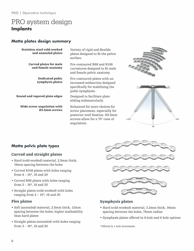
Curved and straight plates
• Hard (cold-worked) material, 2 .5mm thick, 16mm spacing between the holes
• Curved R108 plates with holes ranging from 4 – 16*, 18 and 20
• Curved R88 plates with holes ranging from 3 – 16*, 18 and 20
• Straight plates (cold-worked) with holes ranging from 2 – 16*, 18 and 20
Flex plates
• Soft (annealed) material, 2 .5mm thick, 12mm spacing between the holes, higher malleability than hard plates
• Straight plates (annealed) with holes ranging from 3 – 16*, 18 and 20
Matta plates design summary
Stainless steel cold-worked and annealed plates
Variety of rigid and flexible plates designed to fit the pelvis surface .
Curved plates for male and female anatomy
Pre-contoured R88 and R108 curvatures designed to fit male and female pelvic anatomy .
Dedicated pubic symphysis plates
Pre-contoured plates with an increased midsection designed specifically for stabilizing the pubic symphysis .
Round and tapered plate edges Designed to facilitate plate sliding submuscularly .
Wide screw angulation with Ø3.5mm screws
Enhanced for more choices for screw placement, especially for posterior wall fixation. Ø3.5mm screws allow for a 70° cone of angulation .
*Offered in 1 hole increments .
Matta pelvic plate types
Symphysis plates
• Hard (cold-worked) material, 3 .2mm thick, 16mm spacing between the holes, 75mm radius
• Symphysis plates offered in 4 hole and 6 hole options
PRO system designImplants
PRO | Operative technique
7
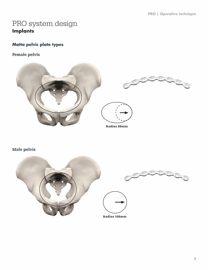
Female pelvis
Matta pelvic plate types
Radius 88mm
Male pelvis
Radius 108mm
PRO system designImplants
PRO | Operative technique
8
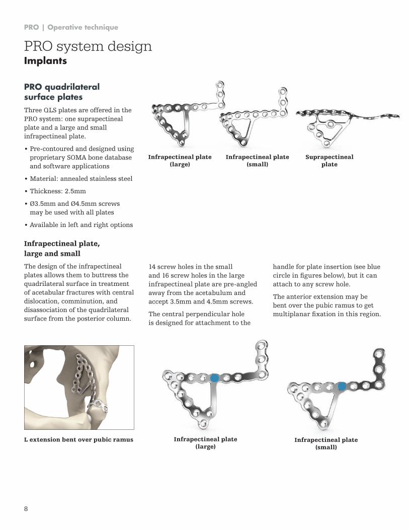
L extension bent over pubic ramus Infrapectineal plate (large)
Infrapectineal plate (small)
PRO quadrilateral surface platesThree QLS plates are offered in the PRO system: one suprapectineal plate and a large and small infrapectineal plate .
• Pre-contoured and designed usingproprietary SOMA bone databaseand software applications
• Material: annealed stainless steel
• Thickness: 2 .5mm
• Ø3.5mm and Ø4.5mm screwsmay be used with all plates
• Available in left and right options
PRO system designImplants
14 screw holes in the small and 16 screw holes in the large infrapectineal plate are pre-angled away from the acetabulum and accept 3 .5mm and 4 .5mm screws .
The central perpendicular hole is designed for attachment to the
Infrapectineal plate (large)
Infrapectineal plate (small)
Suprapectineal plate
Infrapectineal plate, large and small
The design of the infrapectineal plates allows them to buttress the quadrilateral surface in treatment of acetabular fractures with central dislocation, comminution, and disassociation of the quadrilateral surface from the posterior column .
handle for plate insertion (see blue circle in figures below), but it can attach to any screw hole .
The anterior extension may be bent over the pubic ramus to get multiplanar fixation in this region.
PRO | Operative technique
9
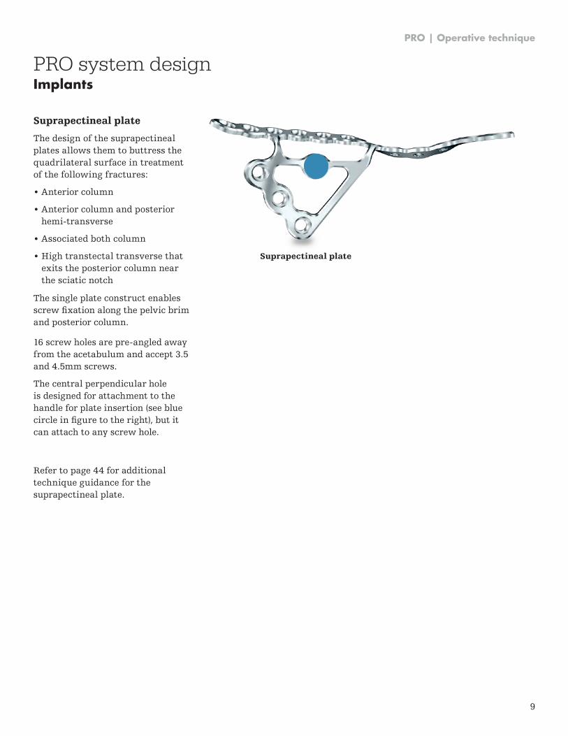
Suprapectineal plate
The design of the suprapectineal plates allows them to buttress the quadrilateral surface in treatment of the following fractures:
• Anterior column
• Anterior column and posterior hemi-transverse
• Associated both column
• High transtectal transverse that exits the posterior column near the sciatic notch
The single plate construct enables screw fixation along the pelvic brim and posterior column .
16 screw holes are pre-angled away from the acetabulum and accept 3 .5 and 4 .5mm screws .
The central perpendicular hole is designed for attachment to the handle for plate insertion (see blue circle in figure to the right), but it can attach to any screw hole .
Refer to page 44 for additional technique guidance for the suprapectineal plate .
Suprapectineal plate
PRO system designImplants
PRO | Operative technique
10
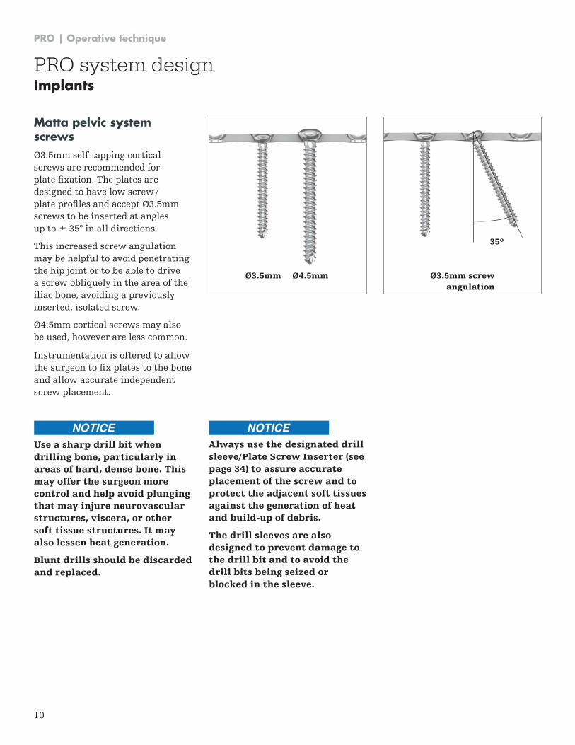
Matta pelvic system screws Ø3.5mm self-tapping cortical screws are recommended for plate fixation. The plates are designed to have low screw / plate profiles and accept Ø3.5mm screws to be inserted at angles up to ± 35° in all directions .
This increased screw angulation may be helpful to avoid penetrating the hip joint or to be able to drive a screw obliquely in the area of the iliac bone, avoiding a previously inserted, isolated screw .
Ø4.5mm cortical screws may also be used, however are less common .
Instrumentation is offered to allow the surgeon to fix plates to the bone and allow accurate independent screw placement .
Use a sharp drill bit when drilling bone, particularly in areas of hard, dense bone. This may offer the surgeon more control and help avoid plunging that may injure neurovascular structures, viscera, or other soft tissue structures. It may also lessen heat generation.
Blunt drills should be discarded and replaced.
35º
Ø3.5mm screw angulation
Ø3.5mm Ø4.5mm
PRO system designImplants
Always use the designated drill sleeve/Plate Screw Inserter (see page 34) to assure accurate placement of the screw and to protect the adjacent soft tissues against the generation of heat and build-up of debris.
The drill sleeves are also designed to prevent damage to the drill bit and to avoid the drill bits being seized or blocked in the sleeve.
NOTICE NOTICE
PRO | Operative technique
11
Instrument design summary
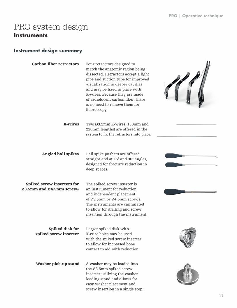
Angled ball spikes
Carbon fiber retractors
Spiked screw inserters for Ø3.5mm and Ø4.5mm screws
Ball spike pushers are offered straight and at 15° and 30° angles, designed for fracture reduction in deep spaces .
Washer pick-up stand A washer may be loaded into the Ø3.5mm spiked screw inserter utilizing the washer loading stand and allows for easy washer placement and screw insertion in a single step .
Four retractors designed to match the anatomic region being dissected . Retractors accept a light pipe and suction tube for improved visualization in deeper cavities and may be fixed in place with K-wires . Because they are made of radiolucent carbon fiber, there is no need to remove them for fluoroscopy.
The spiked screw inserter is an instrument for reduction and independent placement of Ø3.5mm or Ø4.5mm screws. The instruments are cannulated to allow for drilling and screw insertion through the instrument .
Spiked disk for spiked screw inserter
K-wires
Larger spiked disk with K-wire holes may be used with the spiked screw inserter to allow for increased bone contact to aid with reduction .
Two Ø3.2mm K-wires (150mm and 220mm lengths) are offered in the system to fix the retractors into place.
PRO system designInstruments
PRO | Operative technique
12
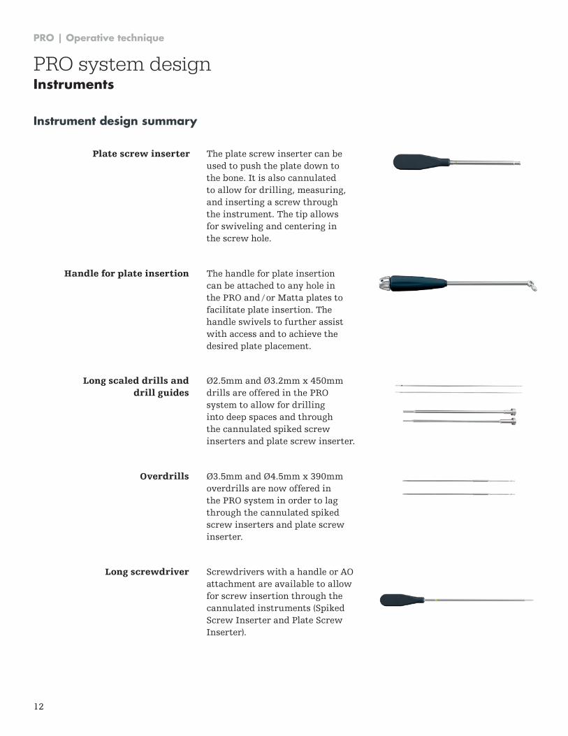
Plate screw inserter The plate screw inserter can be used to push the plate down to the bone . It is also cannulated to allow for drilling, measuring, and inserting a screw through the instrument . The tip allows for swiveling and centering in the screw hole .
Long screwdriver
Overdrills
Screwdrivers with a handle or AO attachment are available to allow for screw insertion through the cannulated instruments (Spiked Screw Inserter and Plate Screw Inserter) .
Ø3.5mm and Ø4.5mm x 390mm overdrills are now offered in the PRO system in order to lag through the cannulated spiked screw inserters and plate screw inserter .
Handle for plate insertion The handle for plate insertion can be attached to any hole in the PRO and / or Matta plates to facilitate plate insertion . The handle swivels to further assist with access and to achieve the desired plate placement .
Long scaled drills and drill guides
Ø2.5mm and Ø3.2mm x 450mm drills are offered in the PRO system to allow for drilling into deep spaces and through the cannulated spiked screw inserters and plate screw inserter .
Instrument design summary
PRO system designInstruments
PRO | Operative technique
13
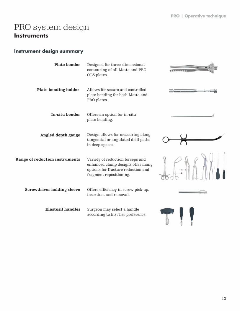
Angled depth gauge Design allows for measuring along tangential or angulated drill paths in deep spaces .
Plate bending holder
In-situ bender
Allows for secure and controlled plate bending for both Matta and PRO plates .
Offers an option for in-situ plate bending .
Plate bender Designed for three-dimensional contouring of all Matta and PRO QLS plates .
Range of reduction instruments
Screwdriver holding sleeve
Variety of reduction forceps and enhanced clamp designs offer many options for fracture reduction and fragment repositioning .
Offers efficiency in screw pick-up, insertion, and removal .
Elastosil handles Surgeon may select a handle according to his / her preference .
Instrument design summary
PRO system designInstruments
PRO | Operative technique
14
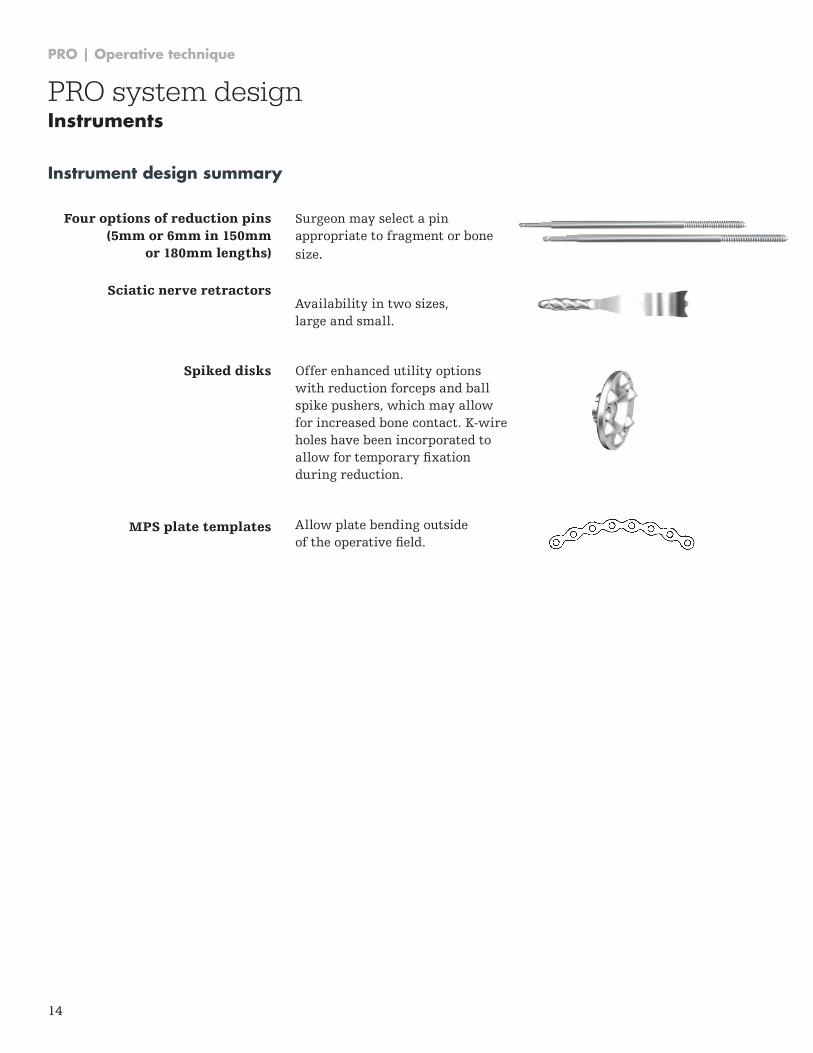
Four options of reduction pins (5mm or 6mm in 150mm
or 180mm lengths)
Sciatic nerve retractors
Spiked disks
MPS plate templates
Surgeon may select a pin appropriate to fragment or bone size .
Availability in two sizes, large and small .
Offer enhanced utility options with reduction forceps and ball spike pushers, which may allow for increased bone contact . K-wire holes have been incorporated to allow for temporary fixation during reduction .
Allow plate bending outside of the operative field.
Instrument design summary
PRO system designInstruments
PRO | Operative technique
15
Tray design summary
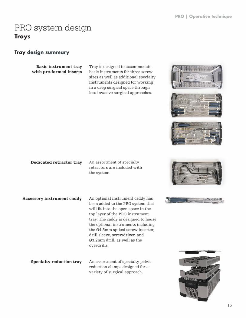
Basic instrument tray with pre-formed inserts
Dedicated retractor tray An assortment of specialty retractors are included with the system .
Tray is designed to accommodate basic instruments for three screw sizes as well as additional specialty instruments designed for working in a deep surgical space through less invasive surgical approaches .
Accessory instrument caddy
Specialty reduction tray
An optional instrument caddy has been added to the PRO system that will fit into the open space in the top layer of the PRO instrument tray . The caddy is designed to house the optional instruments including the Ø4.5mm spiked screw inserter, drill sleeve, screwdriver, and Ø3.2mm drill, as well as the overdrills .
An assortment of specialty pelvic reduction clamps designed for a variety of surgical approach .
PRO system designTrays
PRO | Operative technique
16
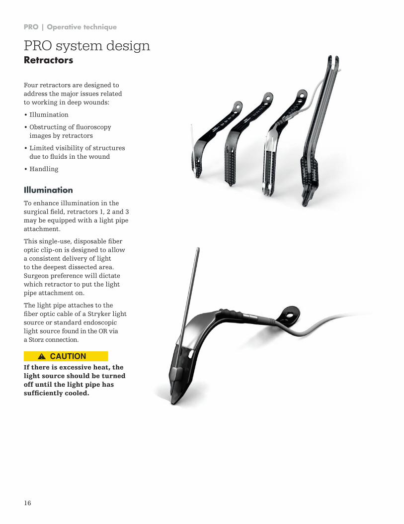
Four retractors are designed to address the major issues related to working in deep wounds:
• Illumination
• Obstructing of fluoroscopy images by retractors
• Limited visibility of structures due to fluids in the wound
• Handling
IlluminationTo enhance illumination in the surgical field, retractors 1, 2 and 3 may be equipped with a light pipe attachment .
This single-use, disposable fiber optic clip-on is designed to allow a consistent delivery of light to the deepest dissected area . Surgeon preference will dictate which retractor to put the light pipe attachment on .
The light pipe attaches to the fiber optic cable of a Stryker light source or standard endoscopic light source found in the OR via a Storz connection .
If there is excessive heat, the light source should be turned off until the light pipe has sufficiently cooled.
PRO system designRetractors
CAUTION
PRO | Operative technique
17
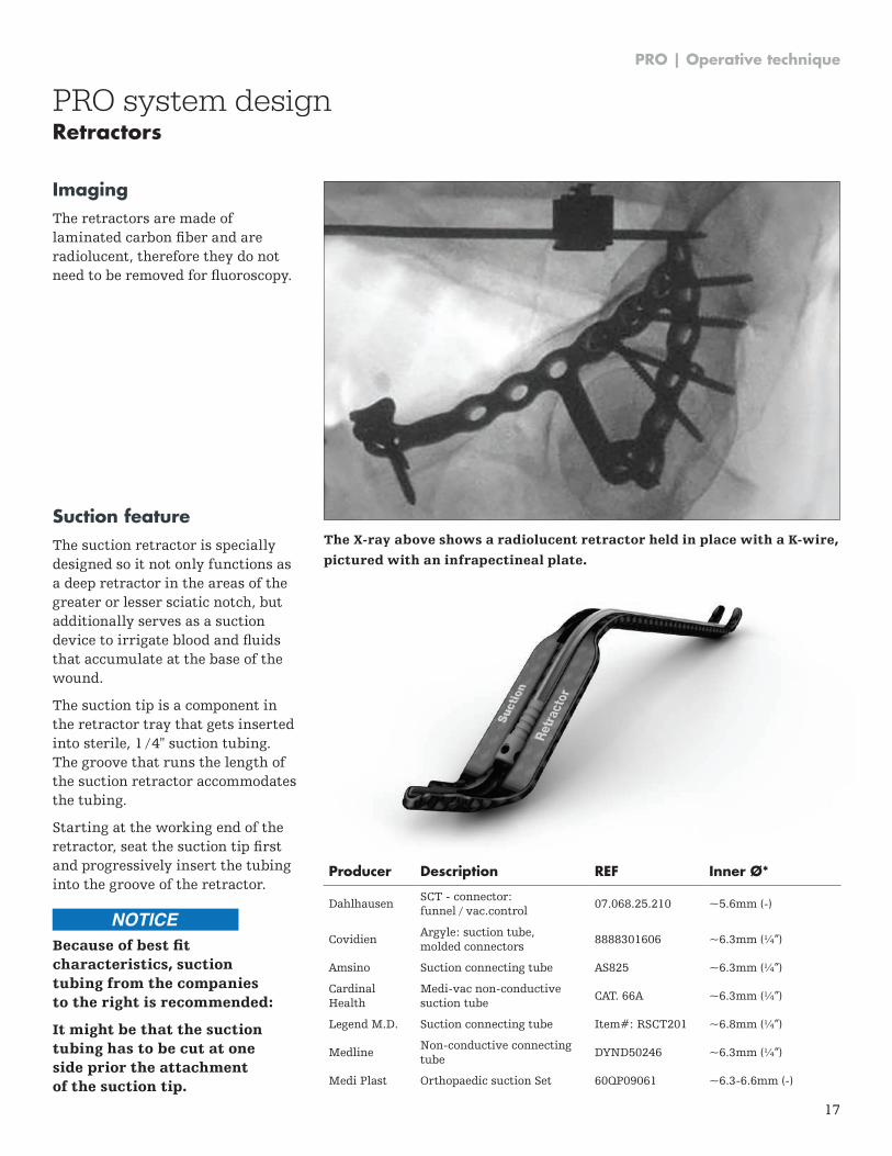
ImagingThe retractors are made of laminated carbon fiber and are radiolucent, therefore they do not need to be removed for fluoroscopy.
Suction featureThe suction retractor is specially designed so it not only functions as a deep retractor in the areas of the greater or lesser sciatic notch, but additionally serves as a suction device to irrigate blood and fluids that accumulate at the base of the wound .
The suction tip is a component in the retractor tray that gets inserted into sterile, 1 / 4" suction tubing . The groove that runs the length of the suction retractor accommodates the tubing .
Starting at the working end of the retractor, seat the suction tip first and progressively insert the tubing into the groove of the retractor .
Because of best fit characteristics, suction tubing from the companies to the right is recommended:
It might be that the suction tubing has to be cut at one side prior the attachment of the suction tip.
PRO system designRetractors
The X-ray above shows a radiolucent retractor held in place with a K-wire,
pictured with an infrapectineal plate.
NOTICE
Producer Description REF Inner Ø*
DahlhausenSCT - connector: funnel / vac .control
07 .068 .25 .210 ~5 .6mm (-)
CovidienArgyle: suction tube, molded connectors
8888301606 ~6 .3mm (¼”)
Amsino Suction connecting tube AS825 ~6 .3mm (¼”)
Cardinal Health
Medi-vac non-conductive suction tube
CAT . 66A ~6 .3mm (¼”)
Legend M .D . Suction connecting tube Item#: RSCT201 ~6 .8mm (¼”)
MedlineNon-conductive connecting tube
DYND50246 ~6 .3mm (¼”)
Medi Plast Orthopaedic suction Set 60QP09061 ~6 .3-6 .6mm (-)
PRO | Operative technique
18
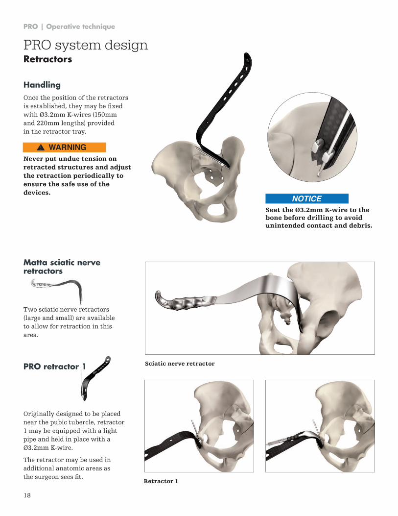
Retractor 1
PRO retractor 1
Originally designed to be placed near the pubic tubercle, retractor 1 may be equipped with a light pipe and held in place with a Ø3.2mm K-wire.
The retractor may be used in additional anatomic areas as the surgeon sees fit.
HandlingOnce the position of the retractors is established, they may be fixed with Ø3.2mm K-wires (150mm and 220mm lengths) provided in the retractor tray .
Never put undue tension on retracted structures and adjust the retraction periodically to ensure the safe use of the devices.
Sciatic nerve retractor
Matta sciatic nerve retractors
Two sciatic nerve retractors (large and small) are available to allow for retraction in this area .
Seat the Ø3.2mm K-wire to the bone before drilling to avoid unintended contact and debris.
PRO system designRetractors
WARNING
NOTICE
PRO | Operative technique
19
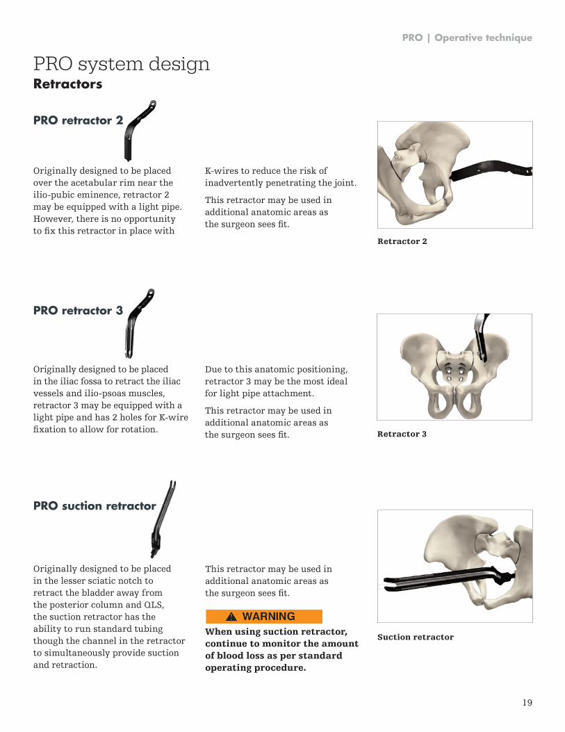
PRO retractor 3
Originally designed to be placed in the iliac fossa to retract the iliac vessels and ilio-psoas muscles, retractor 3 may be equipped with a light pipe and has 2 holes for K-wire fixation to allow for rotation.
PRO retractor 2
Originally designed to be placed over the acetabular rim near the ilio-pubic eminence, retractor 2 may be equipped with a light pipe . However, there is no opportunity to fix this retractor in place with
PRO system designRetractors
K-wires to reduce the risk of inadvertently penetrating the joint .
This retractor may be used in additional anatomic areas as the surgeon sees fit.
Due to this anatomic positioning, retractor 3 may be the most ideal for light pipe attachment .
This retractor may be used in additional anatomic areas as the surgeon sees fit. Retractor 3
Retractor 2
Suction retractor
PRO suction retractor
Originally designed to be placed in the lesser sciatic notch to retract the bladder away from the posterior column and QLS, the suction retractor has the ability to run standard tubing though the channel in the retractor to simultaneously provide suction and retraction .
This retractor may be used in additional anatomic areas as the surgeon sees fit.
When using suction retractor, continue to monitor the amount of blood loss as per standard operating procedure.
CAUTION
PRO | Operative technique
20
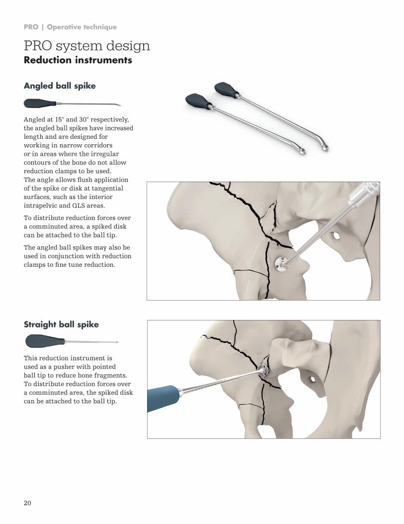
Straight ball spike
This reduction instrument is used as a pusher with pointed ball tip to reduce bone fragments . To distribute reduction forces over a comminuted area, the spiked disk can be attached to the ball tip .
Angled ball spike
Angled at 15° and 30° respectively, the angled ball spikes have increased length and are designed for working in narrow corridors or in areas where the irregular contours of the bone do not allow reduction clamps to be used . The angle allows flush application of the spike or disk at tangential surfaces, such as the interior intrapelvic and QLS areas .
To distribute reduction forces over a comminuted area, a spiked disk can be attached to the ball tip .
The angled ball spikes may also be used in conjunction with reduction clamps to fine tune reduction.
PRO system designReduction instruments
PRO | Operative technique
21
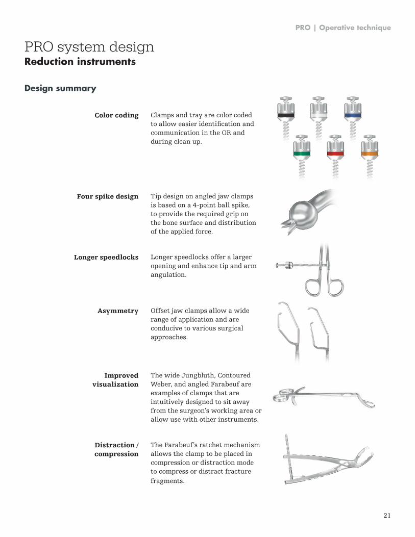
Design summary
PRO system designReduction instruments
Color coding
Four spike design
Longer speedlocks
Asymmetry
Improved visualization
Distraction / compression
Clamps and tray are color coded to allow easier identification and communication in the OR and during clean up .
Tip design on angled jaw clamps is based on a 4-point ball spike, to provide the required grip on the bone surface and distribution of the applied force .
Longer speedlocks offer a larger opening and enhance tip and arm angulation .
Offset jaw clamps allow a wide range of application and are conducive to various surgical approaches .
The wide Jungbluth, Contoured Weber, and angled Farabeuf are examples of clamps that are intuitively designed to sit away from the surgeon’s working area or allow use with other instruments .
The Farabeuf's ratchet mechanism allows the clamp to be placed in compression or distraction mode to compress or distract fracture fragments .
PRO | Operative technique
22
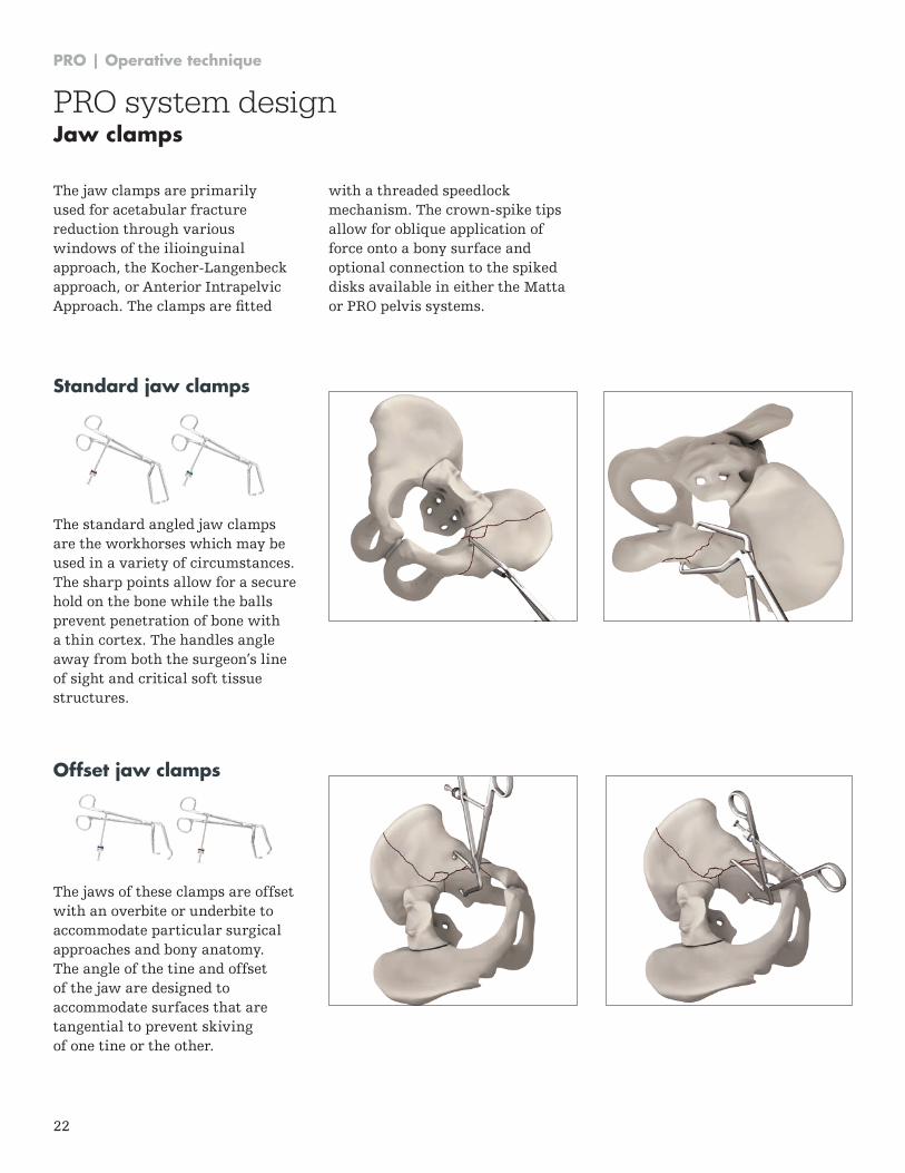
Standard jaw clamps
The standard angled jaw clamps are the workhorses which may be used in a variety of circumstances . The sharp points allow for a secure hold on the bone while the balls prevent penetration of bone with a thin cortex. The handles angle away from both the surgeon’s line of sight and critical soft tissue structures .
The jaw clamps are primarily used for acetabular fracture reduction through various windows of the ilioinguinal approach, the Kocher-Langenbeck approach, or Anterior Intrapelvic Approach. The clamps are fitted
Offset jaw clamps
The jaws of these clamps are offset with an overbite or underbite to accommodate particular surgical approaches and bony anatomy . The angle of the tine and offset of the jaw are designed to accommodate surfaces that are tangential to prevent skiving of one tine or the other .
with a threaded speedlock mechanism . The crown-spike tips allow for oblique application of force onto a bony surface and optional connection to the spiked disks available in either the Matta or PRO pelvis systems .
PRO system designJaw clamps
PRO | Operative technique
23
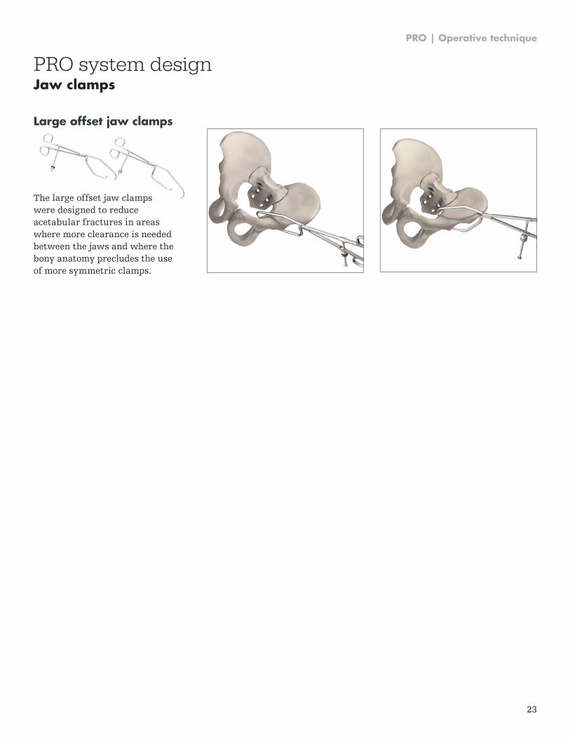
Large offset jaw clamps
The large offset jaw clamps were designed to reduce acetabular fractures in areas where more clearance is needed between the jaws and where the bony anatomy precludes the use of more symmetric clamps .
PRO system designJaw clamps
PRO | Operative technique
24
PRO system designWeber clamps
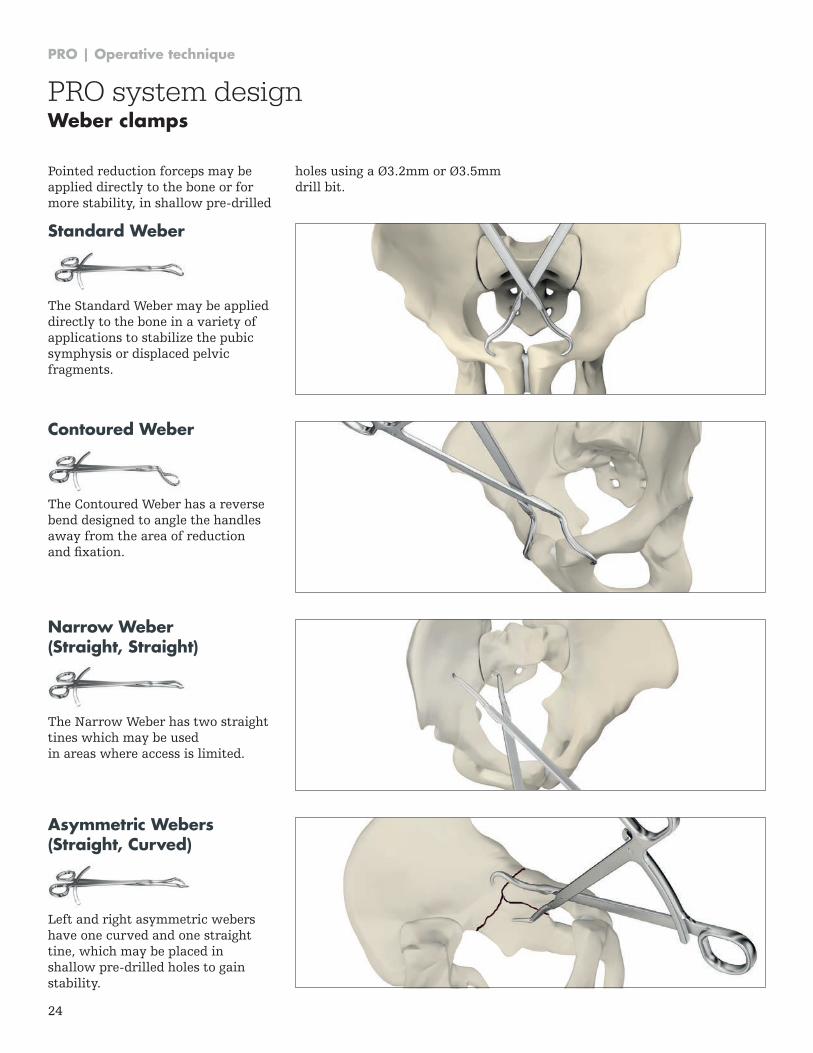
Standard Weber
The Standard Weber may be applied directly to the bone in a variety of applications to stabilize the pubic symphysis or displaced pelvic fragments .
Contoured Weber
The Contoured Weber has a reverse bend designed to angle the handles away from the area of reduction and fixation.
Narrow Weber (Straight, Straight)
The Narrow Weber has two straight tines which may be used in areas where access is limited .
Asymmetric Webers (Straight, Curved)
Left and right asymmetric webers have one curved and one straight tine, which may be placed in shallow pre-drilled holes to gain stability .
Pointed reduction forceps may be applied directly to the bone or for more stability, in shallow pre-drilled
holes using a Ø3.2mm or Ø3.5mm drill bit .
PRO | Operative technique
25
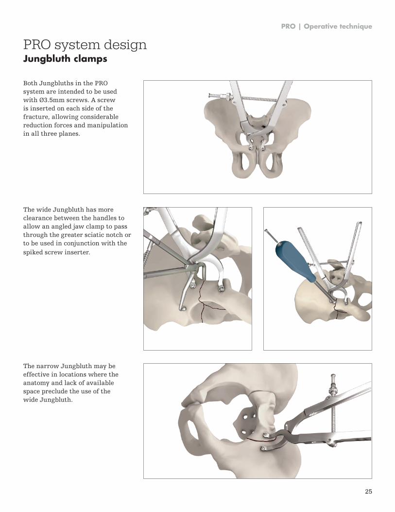
Both Jungbluths in the PRO system are intended to be used with Ø3.5mm screws. A screw is inserted on each side of the fracture, allowing considerable reduction forces and manipulation in all three planes .
The wide Jungbluth has more clearance between the handles to allow an angled jaw clamp to pass through the greater sciatic notch or to be used in conjunction with the spiked screw inserter .
The narrow Jungbluth may be effective in locations where the anatomy and lack of available space preclude the use of the wide Jungbluth .
PRO system designJungbluth clamps
PRO | Operative technique
26
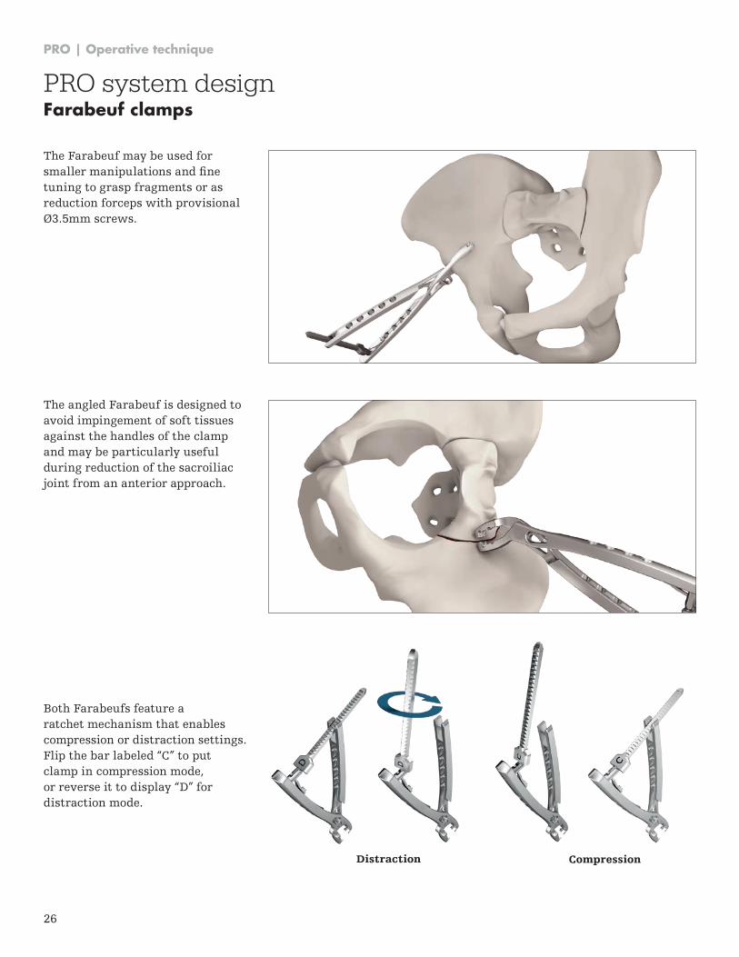
The Farabeuf may be used for smaller manipulations and fine tuning to grasp fragments or as reduction forceps with provisional Ø3.5mm screws.
Both Farabeufs feature a ratchet mechanism that enables compression or distraction settings . Flip the bar labeled “C” to put clamp in compression mode, or reverse it to display “D” for distraction mode .
CompressionDistraction
PRO system designFarabeuf clamps
The angled Farabeuf is designed to avoid impingement of soft tissues against the handles of the clamp and may be particularly useful during reduction of the sacroiliac joint from an anterior approach .
PRO | Operative technique
27
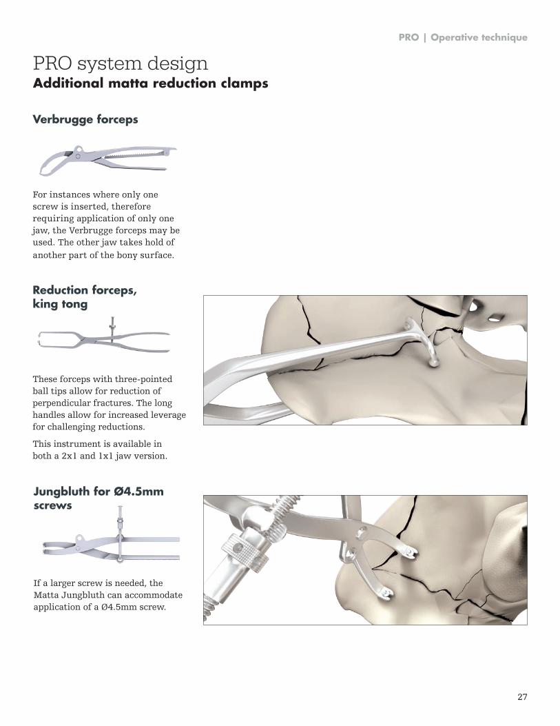
Verbrugge forceps
For instances where only one screw is inserted, therefore requiring application of only one jaw, the Verbrugge forceps may be used . The other jaw takes hold of another part of the bony surface .
Reduction forceps, king tong
These forceps with three-pointed ball tips allow for reduction of perpendicular fractures . The long handles allow for increased leverage for challenging reductions .
This instrument is available in both a 2x1 and 1x1 jaw version.
Jungbluth for Ø4.5mm screws
If a larger screw is needed, the Matta Jungbluth can accommodate application of a Ø4 .5mm screw .
PRO system designAdditional matta reduction clamps
PRO | Operative technique
28
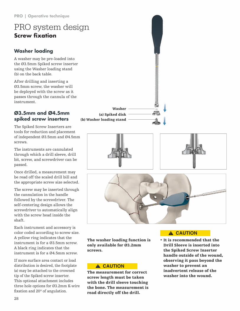
(a) Spiked disk
Washer
(b) Washer loading stand
Ø3.5mm and Ø4.5mm spiked screw insertersThe Spiked Screw Inserters are tools for reduction and placement of independent Ø3 .5mm and Ø4 .5mm screws .
The instruments are cannulated through which a drill sleeve, drill bit, screw, and screwdriver can be passed .
Once drilled, a measurement may be read off the scaled drill bill and the appropriate screw size selected .
The screw may be inserted through the cannulation in the handle followed by the screwdriver . The self-centering design allows the screwdriver to automatically align with the screw head inside the shaft .
Each instrument and accessory is color coded according to screw size . A yellow ring indicates that the instrument is for a Ø3 .5mm screw . A black ring indicates that the instrument is for a Ø4 .5mm screw .
If more surface area contact or load distribution is desired, the footplate (a) may be attached to the crowned tip of the Spiked screw inserter . This optional attachment includes three hole options for Ø3 .2mm K-wire fixation and 20º of angulation.
The washer loading function is only available for Ø3.2mm screws.
The measurement for correct screw length must be taken with the drill sleeve touching the bone. The measurement is read directly off the drill.
• It is recommended that theDrill Sleeve is inserted into the Spiked Screw Inserter handle outside of the wound, observing it pass beyond the washer to prevent an inadvertent release of the washer into the wound.
Washer loading A washer may be pre-loaded into the Ø3 .5mm Spiked screw inserter using the Washer loading stand (b) on the back table .
After drilling and inserting a Ø3 .5mm screw, the washer will be deployed with the screw as it passes through the cannula of the instrument .
PRO system designScrew fixation
CAUTION
CAUTION
PRO | Operative technique
29
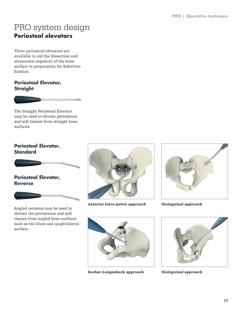
Three periosteal elevators are available to aid the dissection and atraumatic exposure of the bone surface in preparation for definitive fixation.
PRO system designPeriosteal elevators
Periosteal Elevator, Standard
Periosteal Elevator, Reverse
Angled versions may be used toelevate the periosteum and softtissues from angled bone surfacessuch as the ilium and quadrilateralsurface .
Periosteal Elevator, Straight
The Straight Periosteal Elevator may be used to elevate periosteum and soft tissues from straight bone surfaces .
Anterior Intra-pelvic approach
Kocher-Langenbeck approach
Ilioinguinal approach
Ilioinguinal approach
PRO | Operative technique
30
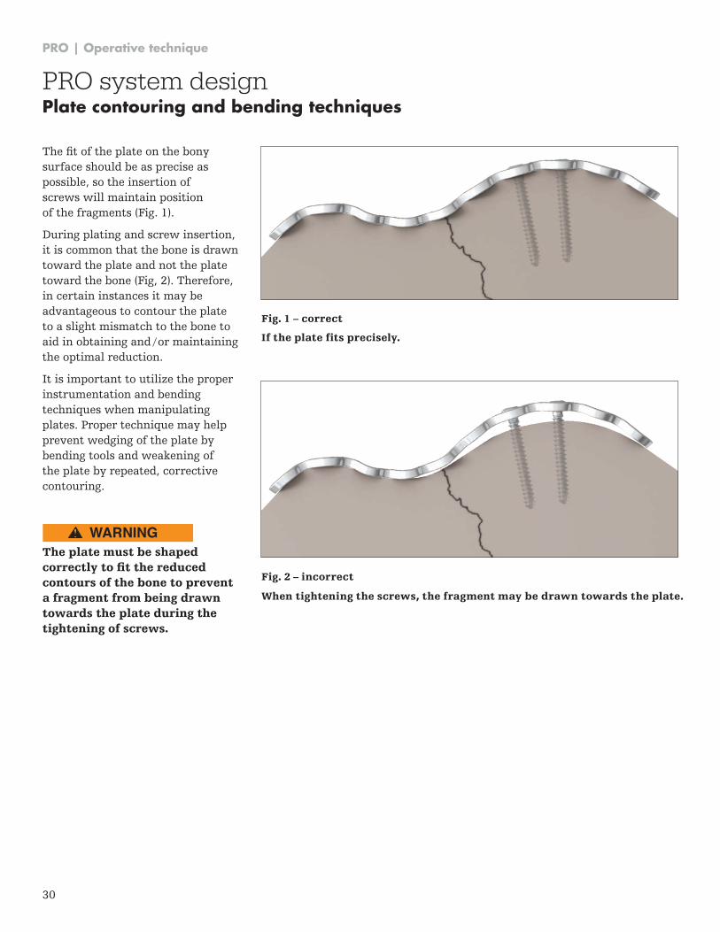
The fit of the plate on the bony surface should be as precise as possible, so the insertion of screws will maintain position of the fragments (Fig . 1) .
During plating and screw insertion, it is common that the bone is drawn toward the plate and not the plate toward the bone (Fig, 2) . Therefore, in certain instances it may be advantageous to contour the plate to a slight mismatch to the bone to aid in obtaining and / or maintaining the optimal reduction .
It is important to utilize the proper instrumentation and bending techniques when manipulating plates . Proper technique may help prevent wedging of the plate by bending tools and weakening of the plate by repeated, corrective contouring .
The plate must be shaped correctly to fit the reduced contours of the bone to prevent a fragment from being drawn towards the plate during the tightening of screws.
If the plate fits precisely.
Fig. 1 – correct
Fig. 2 – incorrect
When tightening the screws, the fragment may be drawn towards the plate.
PRO system designPlate contouring and bending techniques
WARNING
PRO | Operative technique
31
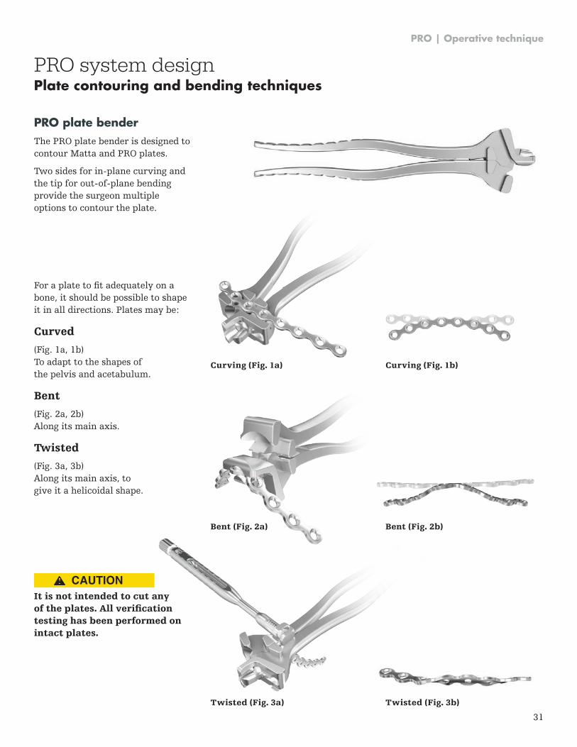
PRO plate benderThe PRO plate bender is designed to contour Matta and PRO plates .
Two sides for in-plane curving and the tip for out-of-plane bending provide the surgeon multiple options to contour the plate .
For a plate to fit adequately on a bone, it should be possible to shape it in all directions . Plates may be:
Curved
(Fig . 1a, 1b) To adapt to the shapes of the pelvis and acetabulum .
Bent
(Fig . 2a, 2b) Along its main axis.
Twisted
(Fig . 3a, 3b) Along its main axis, to give it a helicoidal shape .
It is not intended to cut any of the plates. All verification testing has been performed on intact plates.
Curving (Fig. 1b)Curving (Fig. 1a)
Bent (Fig. 2b)
Twisted (Fig. 3b)
Bent (Fig. 2a)
Twisted (Fig. 3a)
PRO system designPlate contouring and bending techniques
CAUTION
PRO | Operative technique
32
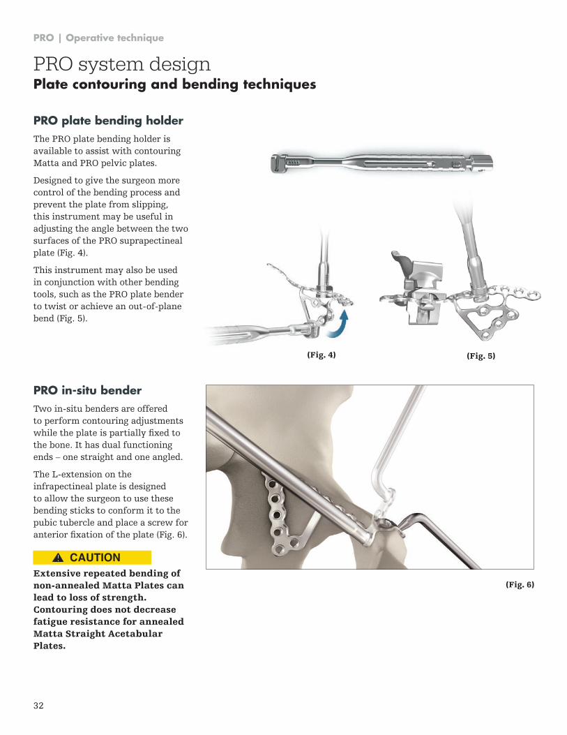
PRO plate bending holderThe PRO plate bending holder is available to assist with contouring Matta and PRO pelvic plates .
Designed to give the surgeon more control of the bending process and prevent the plate from slipping, this instrument may be useful in adjusting the angle between the two surfaces of the PRO suprapectineal plate (Fig . 4) .
This instrument may also be used in conjunction with other bending tools, such as the PRO plate bender to twist or achieve an out-of-plane bend (Fig . 5) .
PRO in-situ benderTwo in-situ benders are offered to perform contouring adjustments while the plate is partially fixed to the bone . It has dual functioning ends – one straight and one angled .
The L-extension on the infrapectineal plate is designed to allow the surgeon to use these bending sticks to conform it to the pubic tubercle and place a screw for anterior fixation of the plate (Fig. 6).
Extensive repeated bending of non-annealed Matta Plates can lead to loss of strength. Contouring does not decrease fatigue resistance for annealed Matta Straight Acetabular Plates.
(Fig. 4) (Fig. 5)
(Fig. 6)
PRO system designPlate contouring and bending techniques
CAUTION
PRO | Operative technique
33
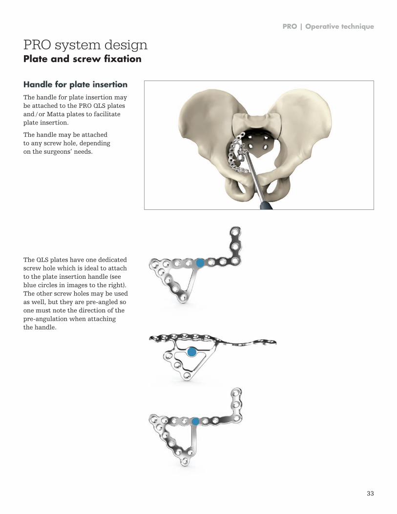
Handle for plate insertionThe handle for plate insertion may be attached to the PRO QLS plates and / or Matta plates to facilitate plate insertion .
The handle may be attached to any screw hole, depending on the surgeons’ needs .
The QLS plates have one dedicated screw hole which is ideal to attach to the plate insertion handle (see blue circles in images to the right) . The other screw holes may be used as well, but they are pre-angled so one must note the direction of the pre-angulation when attaching the handle .
PRO system designPlate and screw fixation
PRO | Operative technique
34
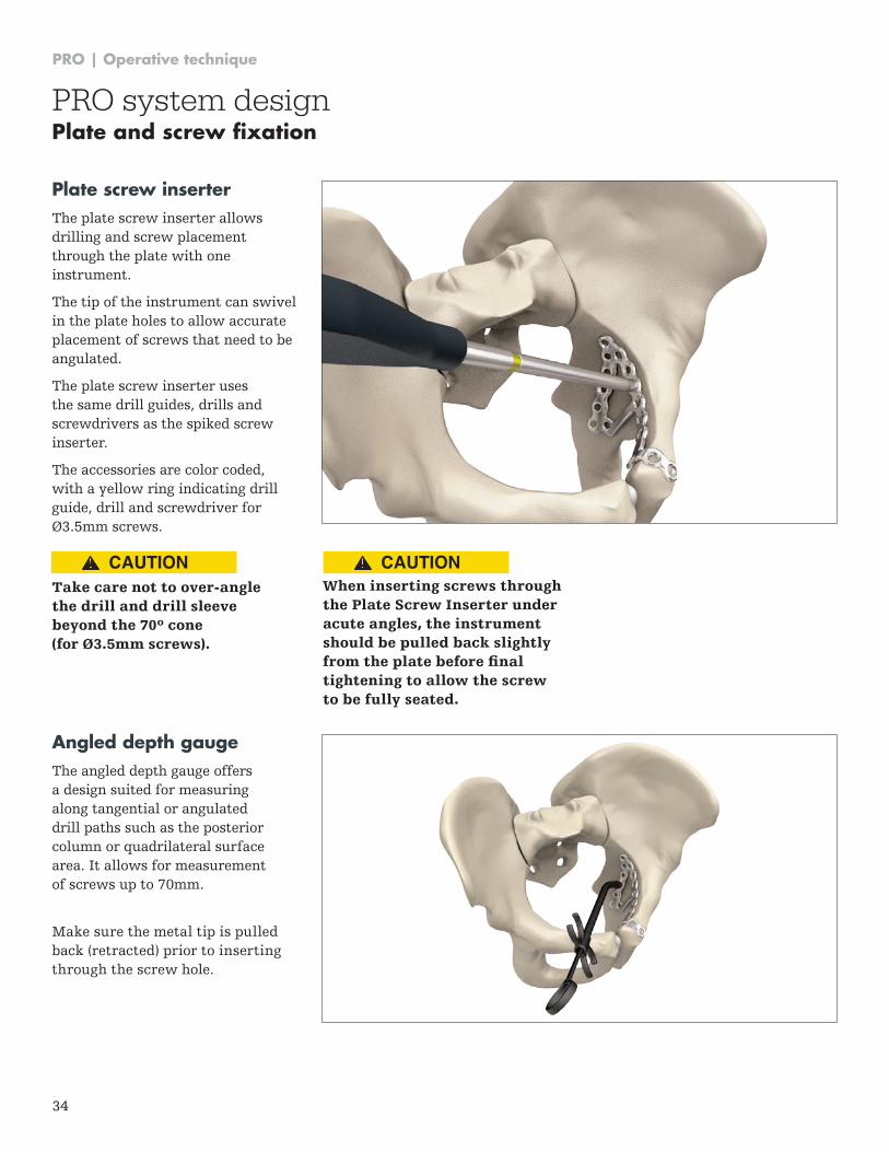
Plate screw inserterThe plate screw inserter allows drilling and screw placement through the plate with one instrument .
The tip of the instrument can swivel in the plate holes to allow accurate placement of screws that need to be angulated .
The plate screw inserter uses the same drill guides, drills and screwdrivers as the spiked screw inserter .
The accessories are color coded, with a yellow ring indicating drill guide, drill and screwdriver for Ø3 .5mm screws .
Take care not to over-angle the drill and drill sleeve beyond the 70º cone (for Ø3.5mm screws).
When inserting screws through the Plate Screw Inserter under acute angles, the instrument should be pulled back slightly from the plate before final tightening to allow the screw to be fully seated.
Angled depth gaugeThe angled depth gauge offers a design suited for measuring along tangential or angulated drill paths such as the posterior column or quadrilateral surface area . It allows for measurement of screws up to 70mm .
Make sure the metal tip is pulled back (retracted) prior to inserting through the screw hole .
PRO system designPlate and screw fixation
CAUTION CAUTION
PRO | Operative technique
35
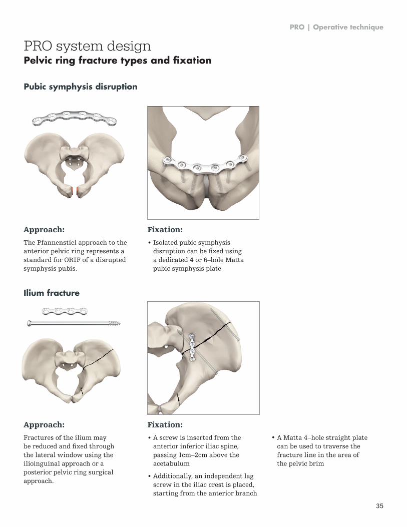
Approach:
The Pfannenstiel approach to the anterior pelvic ring represents a standard for ORIF of a disrupted symphysis pubis .
Fixation:
• Isolated pubic symphysisdisruption can be fixed usinga dedicated 4 or 6–hole Mattapubic symphysis plate
Approach:
Fractures of the ilium may be reduced and fixed through the lateral window using the ilioinguinal approach or a posterior pelvic ring surgical approach .
Fixation:
• A screw is inserted from theanterior inferior iliac spine,passing 1cm–2cm above theacetabulum
• Additionally, an independent lagscrew in the iliac crest is placed,starting from the anterior branch
• A Matta 4–hole straight platecan be used to traverse thefracture line in the area ofthe pelvic brim
Pubic symphysis disruption
Ilium fracture
PRO system designPelvic ring fracture types and fixation
PRO | Operative technique
36
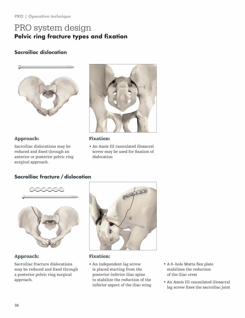
Approach:
Sacroiliac dislocations may be reduced and fixed through an anterior or posterior pelvic ring surgical approach .
Fixation:
• An Asnis III cannulated iliosacral screw may be used for fixation of dislocation
Approach:
Sacroiliac fracture dislocations may be reduced and fixed through a posterior pelvic ring surgical approach .
Fixation:
• An independent lag screw is placed starting from the posterior-inferior iliac spine to stabilize the reduction of the inferior aspect of the iliac wing
• A 6–hole Matta flex plate stabilizes the reduction of the iliac crest
• An Asnis III cannulated iliosacral lag screw fixes the sacroiliac joint
Sacroiliac dislocation
Sacroiliac fracture / dislocation
PRO system designPelvic ring fracture types and fixation
PRO | Operative technique
37
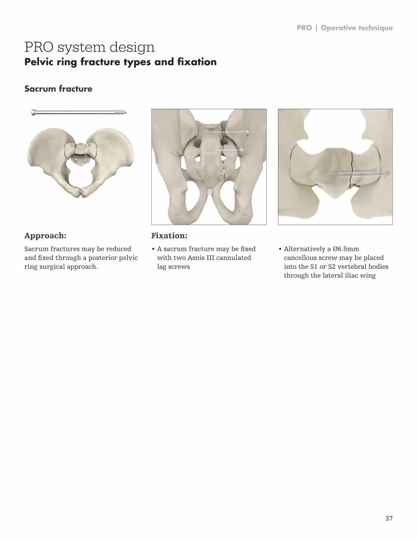
Approach:
Sacrum fractures may be reduced and fixed through a posterior pelvic ring surgical approach .
Fixation:
• A sacrum fracture may be fixedwith two Asnis III cannulatedlag screws
• Alternatively a Ø6.5mmcancellous screw may be placedinto the S1 or S2 vertebral bodiesthrough the lateral iliac wing
Sacrum fracture
PRO system designPelvic ring fracture types and fixation
PRO | Operative technique
38
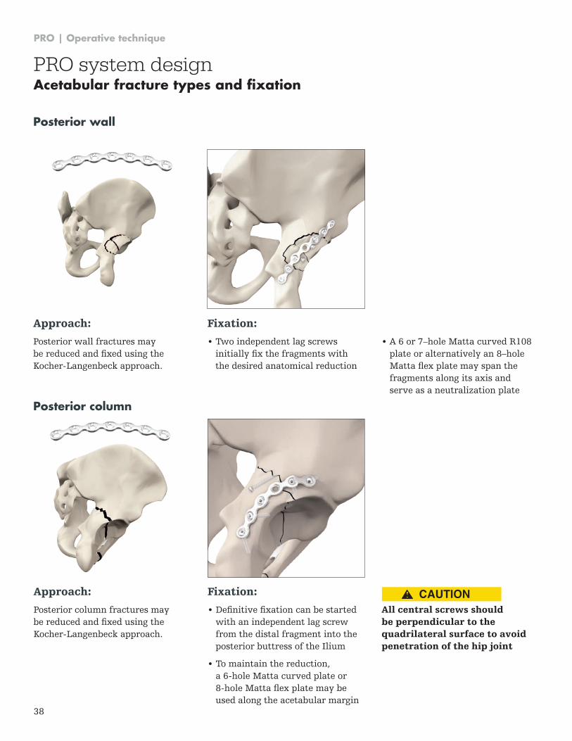
Approach:
Posterior wall fractures may be reduced and fixed using the Kocher-Langenbeck approach .
Fixation:
• Two independent lag screws initially fix the fragments with the desired anatomical reduction
• A 6 or 7–hole Matta curved R108 plate or alternatively an 8–hole Matta flex plate may span the fragments along its axis and serve as a neutralization plate
Posterior wall
Approach:
Posterior column fractures may be reduced and fixed using the Kocher-Langenbeck approach .
Fixation:
• Definitive fixation can be started with an independent lag screw from the distal fragment into the posterior buttress of the Ilium
• To maintain the reduction, a 6-hole Matta curved plate or 8-hole Matta flex plate may be used along the acetabular margin
All central screws should be perpendicular to the quadrilateral surface to avoid penetration of the hip joint
Posterior column
PRO system designAcetabular fracture types and fixation
CAUTION
PRO | Operative technique
39
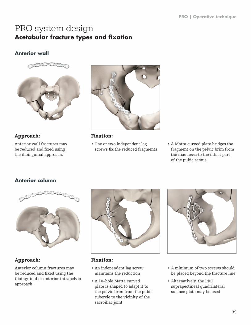
Approach:
Anterior column fractures may be reduced and fixed using the ilioinguinal or anterior intrapelvic approach .
Fixation:
• An independent lag screwmaintains the reduction
• A 10–hole Matta curvedplate is shaped to adapt it tothe pelvic brim from the pubictubercle to the vicinity of thesacroiliac joint
Anterior column
• A minimum of two screws shouldbe placed beyond the fracture line
• Alternatively, the PROsuprapectineal quadrilateralsurface plate may be used
PRO system designAcetabular fracture types and fixation
Approach:
Anterior wall fractures may be reduced and fixed using the ilioinguinal approach .
Fixation:
• One or two independent lagscrews fix the reduced fragments
• A Matta curved plate bridges thefragment on the pelvic brim fromthe iliac fossa to the intact partof the pubic ramus
Anterior wall
PRO | Operative technique
40
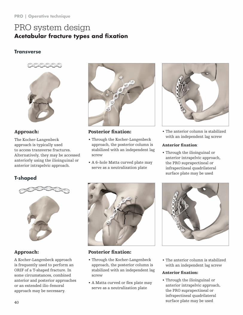
Approach:
The Kocher-Langenbeck approach is typically used to access transverse fractures . Alternatively, they may be accessed anteriorly using the ilioinguinal or anterior intrapelvic approach .
Posterior fixation:
• Through the Kocher-Langenbeck approach, the posterior column is stabilized with an independent lag screw
• A 6–hole Matta curved plate may serve as a neutralization plate
Transverse
• The anterior column is stabilized with an independent lag screw
Anterior fixation:
• Through the ilioinguinal or anterior intrapelvic approach, the PRO suprapectineal or infrapectineal quadrilateral surface plate may be used
Approach:
A Kocher-Langenbeck approach is frequently used to perform an ORIF of a T-shaped fracture . In some circumstances, combined anterior and posterior approaches or an extended ilio-femoral approach may be necessary .
Posterior fixation:
• Through the Kocher-Langenbeck approach, the posterior column is stabilized with an independent lag screw
• A Matta curved or flex plate may serve as a neutralization plate
T-shaped
PRO system designAcetabular fracture types and fixation
• The anterior column is stabilized with an independent lag screw
Anterior fixation:
• Through the ilioinguinal or anterior intrapelvic approach, the PRO suprapectineal or infrapectineal quadrilateral surface plate may be used
PRO | Operative technique
41
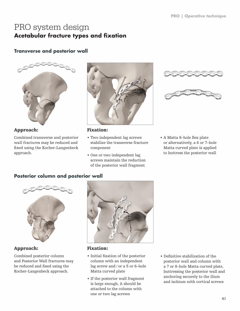
Approach:
Combined transverse and posterior wall fractures may be reduced and fixed using the Kocher-Langenbeck approach .
Fixation:
• Two independent lag screwsstabilize the transverse fracturecomponent
• One or two independent lagscrews maintain the reductionof the posterior wall fragment
• A Matta 8–hole flex plateor alternatively, a 6 or 7–holeMatta curved plate is appliedto buttress the posterior wall
Transverse and posterior wall
Approach:
Combined posterior column and Posterior Wall fractures may be reduced and fixed using the Kocher-Langenbeck approach .
Fixation:
• Initial fixation of the posteriorcolumn with an independentlag screw and / or a 5 or 6–holeMatta curved plate
• If the posterior wall fragmentis large enough, it should beattached to the column withone or two lag screws
Posterior column and posterior wall
PRO system designAcetabular fracture types and fixation
• Definitive stabilization of theposterior wall and column witha 7 or 8–hole Matta curved plate,buttressing the posterior wall andanchoring securely to the iliumand ischium with cortical screws
PRO | Operative technique
42
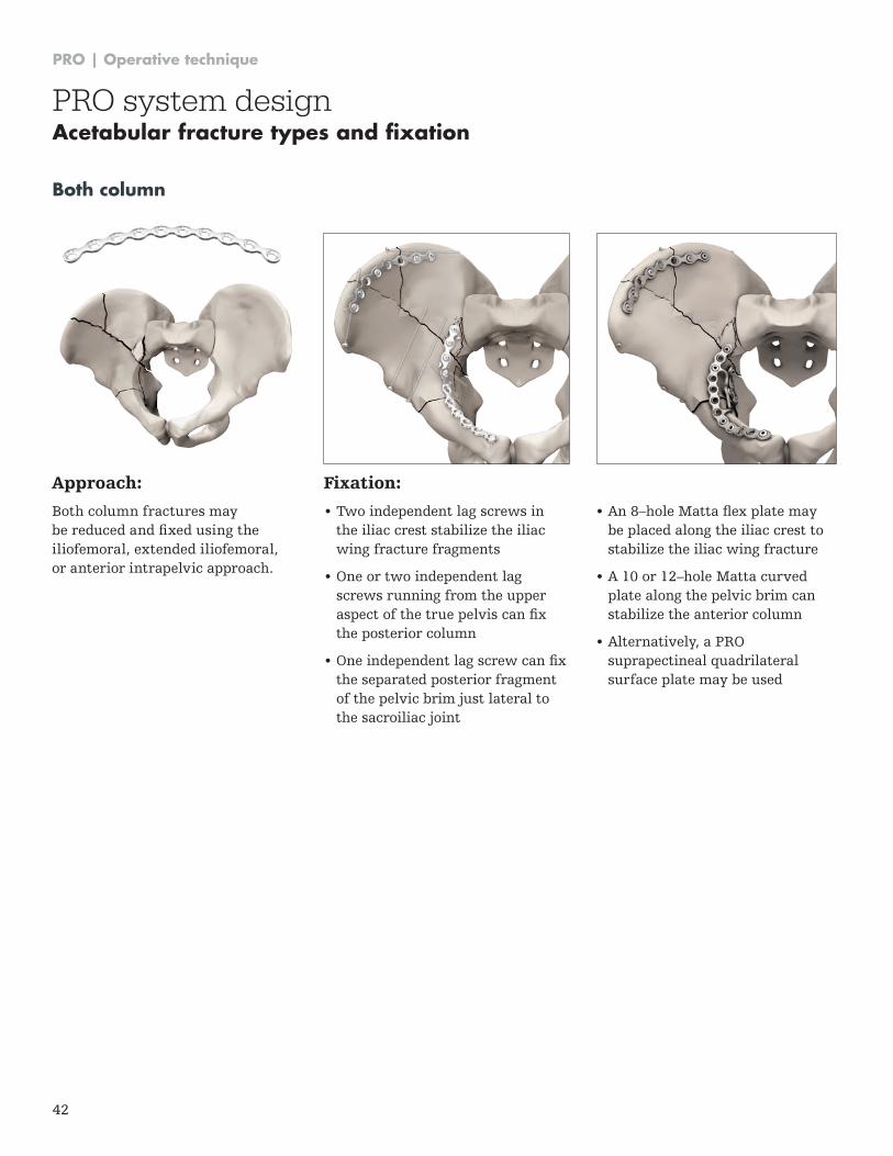
Approach:
Both column fractures may be reduced and fixed using the iliofemoral, extended iliofemoral, or anterior intrapelvic approach .
Fixation:
• Two independent lag screws in the iliac crest stabilize the iliac wing fracture fragments
• One or two independent lag screws running from the upper aspect of the true pelvis can fix the posterior column
• One independent lag screw can fix the separated posterior fragment of the pelvic brim just lateral to the sacroiliac joint
Both column
• An 8–hole Matta flex plate may be placed along the iliac crest to stabilize the iliac wing fracture
• A 10 or 12–hole Matta curved plate along the pelvic brim can stabilize the anterior column
• Alternatively, a PRO suprapectineal quadrilateral surface plate may be used
PRO system designAcetabular fracture types and fixation
PRO | Operative technique
43
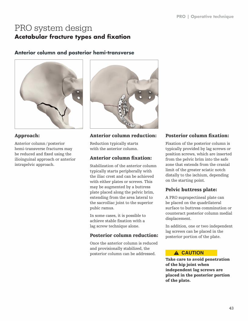
Approach:
Anterior column / posterior hemi-transverse fractures may be reduced and fixed using the ilioinguinal approach or anterior intrapelvic approach .
Anterior column reduction:
Reduction typically starts with the anterior column .
Anterior column fixation:
Stabilization of the anterior column typically starts peripherally with the iliac crest and can be achieved with either plates or screws . This may be augmented by a buttress plate placed along the pelvic brim, extending from the area lateral to the sacroiliac joint to the superior pubic ramus .
In some cases, it is possible to achieve stable fixation with a lag screw technique alone .
Posterior column reduction:
Once the anterior column is reduced and provisionally stabilized, the posterior column can be addressed .
Anterior column and posterior hemi-transverse
Posterior column fixation:
Fixation of the posterior column is typically provided by lag screws or position screws, which are inserted from the pelvic brim into the safe zone that extends from the cranial limit of the greater sciatic notch distally to the ischium, depending on the starting point .
Pelvic buttress plate:
A PRO suprapectineal plate can be placed on the quadrilateral surface to buttress comminution or counteract posterior column medial displacement .
In addition, one or two independent lag screws can be placed in the posterior portion of the plate .
Take care to avoid penetration of the hip joint when independent lag screws are placed in the posterior portion of the plate.
PRO system designAcetabular fracture types and fixation
CAUTION
PRO | Operative technique
44
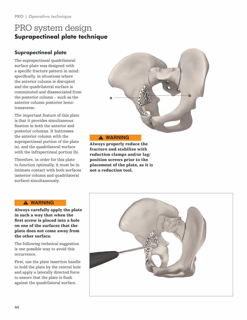
Suprapectineal plate The suprapectineal quadrilateral surface plate was designed with a specific fracture pattern in mind: specifically, in situations where the anterior column is disrupted and the quadrilateral surface is comminuted and disassociated from the posterior column – such as the anterior column posterior hemi-transverse .
The important feature of this plate is that it provides simultaneous fixation in both the anterior and posterior columns . It buttresses the anterior column with the suprapectineal portion of the plate (a), and the quadrilateral surface with the infrapectineal portion (b) .
Therefore, in order for this plate to function optimally, it must be in intimate contact with both surfaces (anterior column and quadrilateral surface) simultaneously .
Always carefully apply the plate in such a way that when the first screw is placed into a hole on one of the surfaces that the plate does not come away from the other surface.
The following technical suggestion is one possible way to avoid this occurrence .
First, use the plate insertion handle to hold the plate by the central hole and apply a laterally directed force to ensure that the plate is flush against the quadrilateral surface .
Always properly reduce the fracture and stabilize with reduction clamps and/or lag/position screws prior to the placement of the plate, as it is not a reduction tool.
a b
PRO system designSuprapectineal plate technique
WARNING
WARNING
PRO | Operative technique
45
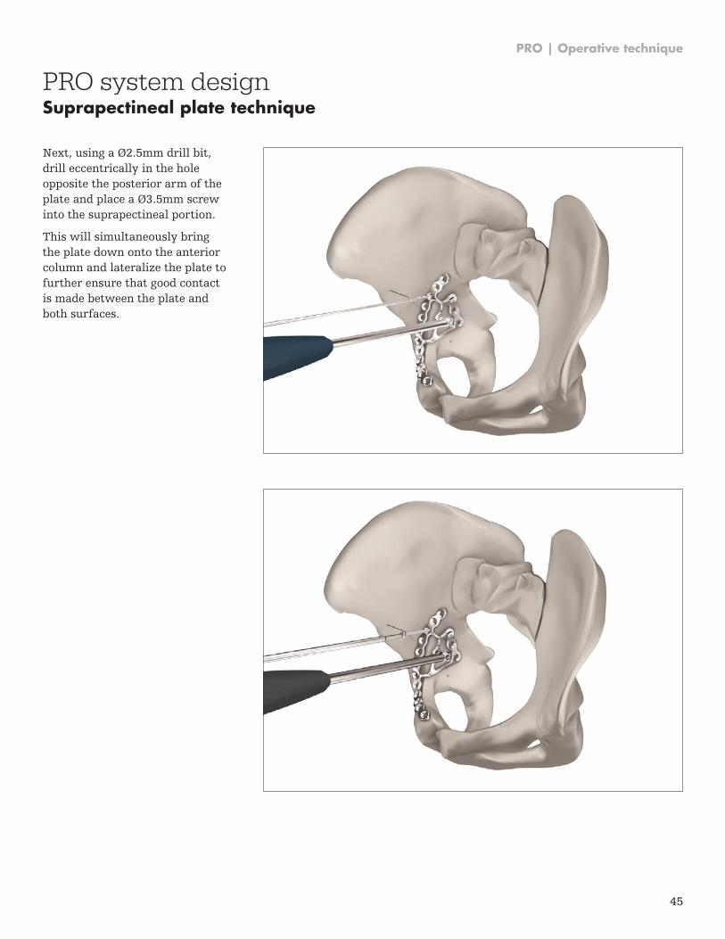
Next, using a Ø2.5mm drill bit, drill eccentrically in the hole opposite the posterior arm of the plate and place a Ø3.5mm screw into the suprapectineal portion .
This will simultaneously bring the plate down onto the anterior column and lateralize the plate to further ensure that good contact is made between the plate and both surfaces .
PRO system designSuprapectineal plate technique
PRO | Operative technique
46
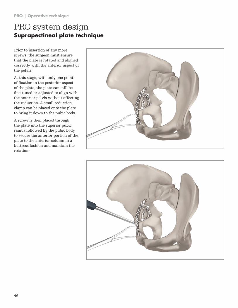
Prior to insertion of any more screws, the surgeon must ensure that the plate is rotated and aligned correctly with the anterior aspect of the pelvis .
At this stage, with only one point of fixation in the posterior aspect of the plate, the plate can still be fine-tuned or adjusted to align with the anterior pelvis without affecting the reduction . A small reduction clamp can be placed onto the plate to bring it down to the pubic body .
A screw is then placed through the plate into the superior pubic ramus followed by the pubic body to secure the anterior portion of the plate to the anterior column in a buttress fashion and maintain the rotation .
PRO system designSuprapectineal plate technique
PRO | Operative technique
47
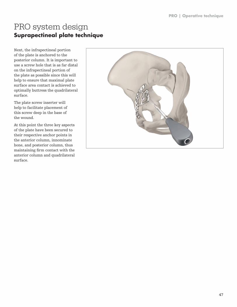
Next, the infrapectineal portion of the plate is anchored to the posterior column . It is important to use a screw hole that is as far distal on the infrapectineal portion of the plate as possible since this will help to ensure that maximal plate surface area contact is achieved to optimally buttress the quadrilateral surface .
The plate screw inserter will help to facilitate placement of this screw deep in the base of the wound .
At this point the three key aspects of the plate have been secured to their respective anchor points in the anterior column, innominate bone, and posterior column, thus maintaining firm contact with the anterior column and quadrilateral surface .
PRO system designSuprapectineal plate technique

This document is intended solely for the use of healthcare professionals . A surgeon must always rely on his or her own professional clinical judgment when deciding whether to use a particular product when treating a particular patient . Stryker does not dispense medical advice and recommends that surgeons be trained in the use of any particular product before using it in surgery .
The information presented is intended to demonstrate a Stryker product . A surgeon must always refer to the package insert, product label and/or instructions for use, including the instructions for Cleaning and Sterilization (if applicable), before using any Stryker product . Products may not be available in all markets because product availability is subject to the regulatory and/or medical practices in individual markets . Please contact your Stryker representative if you have questions about the availability of Stryker products in your area .
Stryker Corporation or its divisions or other corporate affiliated entities own, use or have applied for the following trademarks or service marks: Asnis, Stryker . All other trademarks are trademarks of their respective owners or holders .
The products listed above are CE marked .
Content ID: PRO-ST-1 Rev 3, 06-2017
Copyright 2017
Manufacturer:
Stryker GmbH Bohnackerweg 1 2545 Selzach Switzerland
stryker .com
0123