procedure for the selection and installation of vertical ... · white legend and border. ......
TRANSCRIPT
TM/RID/R/1200.01
Procedure for the Selection and Installation of Vertical Traffic Signs
Procedure No.:
TM/RID/R/1200.01
Originator:
Joe Briffa
Reviewer:
Edric Micallef
Approved for Issue:
Simon Grima
Issue Date:
22/08/2011
Revision:
First Issue
Status:
Controlled
No. of Pages:
12 (Excluding Annexes)
August 2011
Page 1 of 12 Firs

TM/RID/R/1200.01
1 Scope 1.1 This procedure covers the selection of the performance
characteristics and the installation methodology of vertical permanent traffic signs.
2 Acknowledgement 2.1 Transport Malta acknowledges the kind permission of
Leicestershire County Council, Department of Highways, for the use in this document of copyright drawing details and Charts A, B, C and D.
3 Applicability 3.1 This procedure is applicable to arterial and distributor roads.
4 Specifications 4.1 Each and every road section may require specific performance and
installation characteristics. Users of this document are to ensure that the Technical Appendices to the Transport Malta Series 1200 Specification are properly compiled when so required by the prevailing site conditions and that they address the particular technical characteristics of the road section/s under consideration.
5 Current Legislation 5.1 The legislative aspects related to vertical traffic signs are dealt with
in Malta Subsidiary Legislation 65.05.
6 Classes of Vertical Traffic Signs 6.1 There are three (3) main classes of vertical traffic signs:
A. Regulatory Signs (Circular) These comprise all the signs which give notice of requirements, prohibitions or restrictions. They may be supplemented by plates. B. Warning Signs (Triangular) These signs give warning of a hazard ahead. They may be supplemented by plates.
C. Informatory Signs (Rectangular) These are generally directional and provide information about the route.
Page 2 of 12 Draft1 for review

TM/RID/R/1200.01
Note: This procedure does not cover informatory signs related to tourist destinations and facilities, services, parking, cyclists and pedestrians, temporary and emergency, light signals.
7 Illumination of Vertical Traffic Signs 7.1 The illumination requirements for each and every traffic sign are
indicated in the UK Traffic Signs Regulations and General Directions.
7.2 There are two (2) types of vertical traffic sign illumination:
a) Integral to the signface film material by retroreflection b) External to the sign by electrical lighting luminaires. This document covers illumination by retroreflection only.
8 Selecting the Class of Retroreflective Film Material for Traffic Signs
8.1 The retroreflective class requirements recommended for specific road environments shall be as follows:
Table 1 Sign Face Material Selection (Retroreflection)
TM Road Class Prevailing Illumination Bright Lighting with many
External Light Sources Normal Lighting Unlit
Arterial DIN 67520-4, RA3 DIN 67520-4, RA3 DIN 67520-4, RA3 Distributor
(AADT ≥ 19,000) DIN 67520-4, RA3 EN 12899-1, RA2 EN 12899-1, RA2
Distributor (AADT ≤ 19,000)
EN 12899-1, RA2 EN 12899-1, RA2 EN 12899-1, RA2
Tunnels Not applicable EN 12899-1, RA2 Not applicable
Page 3 of 12 Draft1 for review

TM/RID/R/1200.01
9 Signface Film Colours 9.1 The colours of all retroreflective sign face materials shall comply
with the chromaticity requirements of EN 12899-1.
10 Sign Post Colours 10.1 The sign posts must be galnanised and need not be painted
(excluding Zebra crossing beacons, hazard markers, load gauges and portable traffic signals).
10.2 To conserve uniformity and reduce maintenance costs the natural “grey” colour of proprietary galvanic coatings should be adopted.
10.2.1 Should it become necessary the “grey” standard colour indicated in Table 2 shall be used for the painting of posts and fittings:
Table 2 Traffic Signs - Standard “Grey” Colour for Posts and Fittings1
Colour BS 381C (Number) Common Name Notes Grey 693 Aircraft Grey Posts, fittings, Sign
faces and backs of signs 10.3 The backs of signs, bracing and painted fixing clips must be grey.
11 Regulatory Signs 11.1 Sign Sizes 11.2 The size of regulatory signs shall be appropriate for the prevailing
traffic speed for the section of road in which they are erected. For the purpose of this procedure the prevailing traffic speed shall be equated to the 85th percentile approach speed2.
11.3 The size of regulatory signs shall be as indicated in Annex 1. 11.4 Visibility 11.4.1 The desirable minimum clear sightline distances for signs shall be
the following: Table 3: Minimum Clear Visibility Distances3
85th Percentile speed of
private cars (km/h) Minimum clear visibility distance (m)
1 See UK TSM1, Appendix 1; 2 See TM Volume 5, ADT TD 9/00, Chapter 1 3 See UK TSM3, Table 1-1; UK TSM4, appendix A.
Page 4 of 12 Draft1 for review

TM/RID/R/1200.01
Up to 30 45 31 to 50 60 51 to 60 60 61 to 80 75
11.5 “STOP” and “GIVE WAY” Regulatory Signs 11.5.1 The desirable distances and size of “STOP” and “GIVE WAY” signs
shall be the following: Table 4: STOP and GIVE WAY Regulatory Signs4
STOP GIVE WAY 85th Percentile
speed of private cars (km/h)
Sign Size (mm) Visibility Distance (m)
Sign Size (mm)
Up to 30 750 15 600 31 to 50 750 30 600 51 to 60 900 (750) 45 750 (600) 61 to 80 1200 (900) 70 900 (750)
12 Warning Signs 12.1 The desirable sign sizes and the distance of the sign from the
hazard shall be as follows: Table 5: Warning Signs - Size and distance from Hazard5
85th Percentile speed of private cars (km/h)
Height of Triangular warning signs (mm)
Supplementary plate (x-height, mm)
Distance of sign from hazard (m)
Up to 30 600 62.5 45 31 to 50 600 62.5 45 51 to 60 750 (600) 75 (62.5) 45-110 61 to 80 900 (750) 100 (75) 110-180
4 See UK TSM3, Tables 3-1, 3-2, 3-3; 5 See UK TSM4, Appendix A
Page 5 of 12 Draft1 for review

TM/RID/R/1200.01
13 Informatory Direction Signs 13.1 Route Status6 13.1.1 Contrary to UK practice the status of arterial, distributor and
secondary roads in Malta is not denoted by specific colour coding. 13.2 Types of Directional Signs 13.2.1 The following types of Directional informatory signs may be used:
i. Advance Direction Signs ii. Direction Signs
13.3 Colour 13.3.1 Informatory direction signs shall have a blue background with a
white legend and border. 13.4 Form and Arrangement 13.4.1 The form and arrangement shall be as selected from one of the
following:
13.4.1.1 Advance Direction Signs (Post – Mounted)
i. Advance Direction Map type ii. Advance Direction Stack type iii. Advance Direction Dedicated Lane
13.4.1.2 Advance Direction Signs (Gantry – Mounted)
i. Advance Direction Sign for Junction without Lane Drop ii. Advance Direction Sign for Junction with Lane Drop
13.4.1.3 Direction Signs (Low or High – Post Mounted)
i. Direction Flag Type (Junction, Chevroned) ii. Direction Rectangular (Junction, Arrowed)
13.5 Route Numbers and Distances 13.5.1 The route number shall be inserted in brackets. 13.5.2 The distance may be indicated as follows:
i. In Advance Direction Signs.
6 For UK practice see LTN 1/94
Page 6 of 12 Draft1 for review

TM/RID/R/1200.01
ii. In Direction Signs. 13.6 Alphabet 13.7 The alphanumeric characters used in traffic signs shall be the UK
Transport Medium style7 amended as required to include Maltese language markers – See Annex 2.
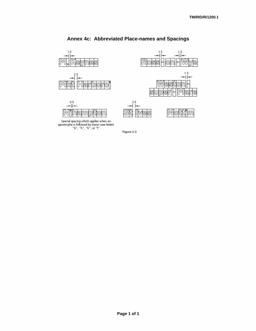
13.8 “Tiles” and “Tile Size” 13.8.1 To ensure the proper letter spacing the characters shall be placed
on virtual “tiles” (See Annex 1).8 13.8.2 All design spaces shall be measured to the edge of the virtual “tile”
and not to the actual characters. 13.8.3 The size of the alphabet shall be specified in terms of its “x-height”.
This is defined as the height of the lower case letter “x “. The “x-heights” shall be as indicated in Annex 3.
13.8.4 The unit of measurement shall be the “stroke width (sw)” which is ¼ of the “x-height”.
13.8.5 The tile height shall be twice (2 times) the “x-height”. 13.8.6 The tile width shall be as indicated in Annex 4d. 13.8.7 The spacing between two (2) words shall be 2.5sw. 13.8.8 The standard border shall have a width of 1.5sw and a radius of 1.5sw. Table 6: Sign Letter Sizing Ratios - Summary
Element Ratio Notes x-height = 4sw tile height = 2 times the x-height tile height = 8sw tile width See Annex 4d9 UK DfT Drawings
TM1, TM2, TM3 – See Annex 2
Spacing between 2 words
= 2.5sw
Width of standard border
= 1.5sw
7 See UK TSRGD, Part 1, Schedule 13. 8 For guidance see UK TSM7, 2 9 See UK TSM7, Appendix C
Page 7 of 12 Draft1 for review
TM/RID/R/1200.01
13.9 Panels 13.9.1 The use of panels is permitted. 13.9.2 Panels of the appropriate background colour may be used on both
advance direction and direction signs to indicate cycle routes and tourist attractions.
13.9.3 Panels with place name destinations shall not be used on flag type direction signs.
13.9.4 The use of “patches” designating a route number is prohibited.
14 The Positioning of Traffic Signs 14.1 Siting 14.1.1 Drivers in Malta are accustomed to signs being sited on the
nearside of the carriageway. Such positioning should therefore represent the general practice.
14.1.2 Siting on the offside is however appropriate in certain circumstances; Examples: Sign duplication (No Entry), Sharp left-hand bends, Roundabouts, Refuges.
14.1.3 At tunnels and underpasses overhead signs may be more appropriate.
14.2 Relaxations and Departures from the Minimum Standard 14.2.1 Achieving desirable minimum standards may not always be
possible due to specific site constraints. Where rectification would result in only a minimal cost-benefit improvement “relaxations” may be considered.
14.2.2 In situations which cannot be overcome even by “relaxations” a “departure” from standard is required.
14.2.3 Such “relaxations” and “departures” must be documented and signed in the Project File.
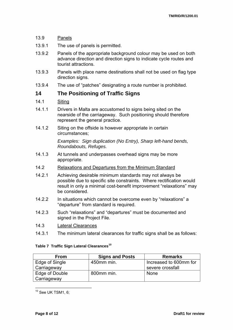
14.3 Lateral Clearances 14.3.1 The minimum lateral clearances for traffic signs shall be as follows: Table 7 Traffic Sign Lateral Clearances10
From Signs and Posts Remarks
Edge of Single Carriageway
450mm min. Increased to 600mm for severe crossfall
Edge of Double Carriageway
800mm min. None
10 See UK TSM1, 6;
Page 8 of 12 Draft1 for review

TM/RID/R/1200.01
From Signs and Posts Remarks Edge of Cycleway 500mm min. None Edge of Central Reserve of Dual Carriageway
600mm min. None
Hard Verge 600mm min. From hardening 14.3.2 When posts are erected in narrow footpaths the clear walkway
width should not be less than 1.0m. 14.4 Mounting Heights 14.4.1 The minimum mounting heights for traffic signs shall be as follows: Table 8 Traffic Sign Mounting Heights11
Sign Type
Edge Regulatory / Warning / Information
Direction
Verge 2.2m 1.2 / 1.8m#
Footpath 2.3m 2.3m Cycleway 2.4m 2.4m Footpath / Cycleway 2.4m 2.4m Note
# 1.8m desirable to avoid tyre splash
11 See UK TSM1, 6;
Page 9 of 12 Draft1 for review

TM/RID/R/1200.01
14.4.2 No assembly should exceed 4.0m in overall height above ground level unless absolutely necessary to ensure the visibility of the signs at particularly difficult locations.
14.5 Orientation 14.5.1 To avoid or minimise specular reflection (mirror-like reflection) the
signs should be set at the orientation angles indicated in TM Drawing 35/11.
14.6 Sign Overloading 14.6.1 Research and experience has indicated that drivers can only
assimilate a limited amount of information whilst driving12. Sign overloading should therefore be avoided. This is applicable to signs mounted on both single or separate posts.13
14.6.2 Generally not more than two (2) signs should be mounted on any one (1) post. Supplementary plates may be regarded as one (1) sign.
14.6.3 Exceptionally, three (3) signs may be erected on any one (1) post provided that none requires a supplementary plate.
14.7 Order of Sign Combinations 14.7.1 A warning sign/s should not be mounted on the same post as a
“STOP” or “GIVE WAY” or terminal “SPEED LIMIT” sign. 14.7.2 The permitted sign combinations should be placed in the following
order from top to bottom:
a) “Stop” or “Give Way” or any triangular warning sign/s; b) Speed Limit signs; c) Other circular signs; d) Rectangular signs;
14.7.3 Where two (2) or more warning signs are mounted together the
sign relating to the hazard first encountered should be placed upper-most.
14.7.4 Where rectangular signs are erected together or a supplementary plate is mounted below a triangular sign, the signs should be separated by a space not exceeding the “x-height” of the lettering on the lower sign. All other signs may be butted together, one above the other.
12 Information overloading increases with age; See TSM3, 1.25 and TSM 4, 1.26 13 Experience from the Naxxar-Salini Road Traffic Sign “Pilot” Project indicated sign overloading due to the heavy concentration of road hazards over a short distance especially “Concealed Exits”.
Page 10 of 12 Draft1 for review

TM/RID/R/1200.01
14.8 Tolerance for Re-siting Distance 14.8.1 Permanent features which cannot be altered (bends, crests,
buildings, accesses, trees, boundary walls, lighting columns, bus stops, etc) may require that particular signs be re-sited from their desirable position. In such cases it is preferable to increase the standard distance between the sign and the site to which it relates rather than reduce it. Such re-location should not increase the distance by more than 10%. Greater variations shall require the insertion of a signed “Relaxation” or “Departure” from the Standard in the project file.
15 Traffic Sign Post and Foundations - Sizing 15.1 The traffic sign post and foundation sizing shall be selected as
follows: i. Using the example in TM Drawing RD 35/11 calculate:
a. the area of each sign erected on the post (See Table 10 for standard areas)
b. the total sign area on the post (Add all areas); c. the height of all the signs on the post; d. the height to the centroid.
ii. Using Charts A or B select: iii. The number of posts; iv. The post diameter and wall thickness (See Table 10 for wall
thickness); v. The foundation Type A to I; vi. Using Transport Drawing RD 35/11 and Chart C select the
appropriate foundation width, depth and length. Table 9: Areas of Non-Rectangular Signs Type of Basic Sign
Size (mm) Area (m2) Working Drawing Reference14
STOP 750 0.47 UK DfT Drg. P601.1 STOP (900) 0.67 UK DfT Drg. P601.1 STOP (1200) 1.19 UK DfT Drg. P601.1 Roundel (600) 0.28 Roundel 750 0.44 Roundel (900) 0.63 Roundel (1200) 1.13
Example - UK DfT Drg. P616
Triangle 600 0.24 UK DfT Drg. P500 Triangle (750) 0.37 UK DfT Drg. P500 Triangle (900) 0.53 UK DfT Drg. P500 Triangle (1200) 0.94 UK DfT Drg. P500
14 UK Department of Transport Working Drawings
Page 11 of 12 Draft1 for review

TM/RID/R/1200.01
Table 10: Tubular Posts - Wall Thickness
Standard Outside Diameter (mm)
Wall Thickness (mm)
Tensile Yield (N/mm2)
60.3 3.2 76.1 4 88.9 5
114.3 6.3 139.7 8 168.3 8 193.7 10 219.1 12
EN 10210-1 and
EN 10210-2
Type S275JOH / S275J2H
244.5 12
275 (Min.)
16 Annexes 1 Sizes of Regulatory Traffic Signs 2 Transport Medium Alphabet - UK DfT Drawings TM1,
TM2, TM3 3 Directional Signs – “x-heights” and Siting Distances 4a Placement of Characters on the Virtual “Tiles” 4b Horizontal Spacing of Different Sign Elements 4c Abbreviated Place-names and Spacings 4d Tile (Virtual) Widths
17 Reference Documents 1 Malta Subsidiary Legislation 65.05 2 The Highway Code (Malta) 3 ADT MCRW, 2003, Volume1, Series 1200 4 ADT MCRW, 2003, Volume 2, Series NG1200 5 UK TSRGD, 2002 6 UK TSM1, TSM3, TSM4, TSM7 7 UK LTN 1/94 8 UK Leicestershire County Council, Department of
Highways, Drawings SD/12/1 to 6, 8, 9, 13 to 15 (with permission)
9 MSA EN 12899-1 10 DIN 67520-4
Page 12 of 12 Draft1 for review

TM/RID/R/1200.1
Annex 1: Sizes of Regulatory Traffic Signs (All references and notes relate to the UK Traffic Signs Manual, Chapter 3). Diagram Number Dimension 85th percentile speed of private cars (km/h)
Up to 30 31 to 50 51 to 60 61 to 80 81 to 100 Over 100570 x-height - 62.5 62.5 (75) 75 (100) 100 (125) 125 (150)601.1 See Table 3.2 602 See Table 3.2 606 (Note 5) Diameter 607 x-height 608 x-height 609 x-height 610 (Note 6) Diameter
611 (Note 6) Diameter 450 (450) 600 (600) 750 (750) 900 (900) 1200 1200
611.1 (Note 7) Diameter 600 600 (750) 750 (900) - - -
612 (Note 5) Diameter 450 (450) 600 (600) 750 (750) 900 (900) 1200 1200
613 (Note 5) Diameter 450 (450) 600 (600) 750 (750) 900 (900) 1200 1200
614 (Note 5) Diameter 450 600 600 (750) 750 (900) 900 (1200) 1200
615 Diameter 600 750 (750) 900 (900) 1200 1200 -
615.1 x-height 62.5 75 (75) 100 (100) 125 125 -
616 (Note 5,11) Diameter (450) 600 (600) 750 750 (750) 900 (900) 1200 1200
617 Diameter 450 (450) 600 (600) 750 (750) 900 (900) 1200 1200
618 x-height (37.5) 50 (50) 62.5 - - - -618.1 x-height (37.5) 50 (50) 62.5 (62.5) 75 (75) 100 100 -618.2 One size only 618.3 One size only 618.3A One size only 618.4 One size only 619 (Note 12) Diameter 450 (450) 600 (600) 750 (750) 900 (900)
1200 1200
619.1 Diameter 450 (450) 600 (600) 750 (750) 900 (900) 1200 1200
619.2 Diameter 450 (450) 600 (600) 750 (750) 900 (900) 1200 1200
620 (Note 13) x-height (37.5) 50 (50) 62.5 (62.5) 75 (75) 100 (100) 125 125 620.1 x-height (37.5) 50 (50) 62.5 (62.5) 75 (75) 100 (100) 125 125
622.1A Diameter 450 (450) 600 (600) 750 (750) 900 (900) 1200
1200 (1500)
622.2 Diameter 450 (450) 600 600 750 (750) 900 900 622.4 Diameter 600 600 (600) 750 (750) 900 900 -622.5 The size of this sign is not related to traffic speed (see Note 8) 622.6 The size of this sign is not related to traffic speed (see Note 8)
622.7 Diameter 450 (450) 600 (600) 750 (750) 900 (900) 1200 -
622.8 Diameter 450 600 750 900 1200 1200 622.9 x-height (37.5) 50 62.5 75 100 125 125 625.1 The size of this sign is not related to traffic speed (see Note 8) 629A Diameter 750 750 (750) 900 (900) 1200 -
Page 1 of 5

TM/RID/R/1200.1
Diagram Number Dimension 85th percentile speed of private cars (km/h)
Up to 30 31 to 50 51 to 60 61 to 80 81 to 100 Over 1001200
629.1 Diameter 600 600 (600) 750 (750) 900 900 -629.2A Diameter 750 750 900 1200 1500 1500
632 Diameter - 600 600 (750) 750 (900) 900 (1200) -
633 Diameter 450 (the larger size of 540 can be used at the discretion of the police) 636 See para 6.27 636.1 See working drawing P 636.1 636.2 One size only 637.1 See para 6.33 637.2 One size only 637.3 See para 6.33 638 See para 6.33 638.1 See para 6.33 639 See para 6.33 639.1B See para 7.47 640 See para 6.33 640.1 To suit size of parking meter cover and legend used 640.2A See para 6.33 640.3 One size only 640.4 One size only 640.5 One size only
642 (Terminal) Diameter 450 600 600 (750) 750 (900) 900 900 (1200)
642 (Repeater) Diameter - 300 300 450 450 600 642.2A One size only 642.3 See para 9.13 645 x-height 50 62.5 75 (100) 100 (125) 125 (150) 150 (200) 646 See para 9.10 647 One size only 650.1 See para 9.29 650.2 See para 6.33 650.3 See para 6.33 651 See para 5.30 652 Height 450 450 450 675 675 675 660 See para 7.47 660.3 See para 7.47 660.4 See para 7.47 660.5 See para 7.47 660.6 See para 7.47 660.7 See para 7.47 661A See para 7.47 661.1 See para 7.47 661.2A See para 7.47 661.3A See para 7.47 661.4 See para 7.47 662 See paras 7.47 and 12.23 663 See para 12.20 663.1 See para 12.20 664 See para 12.20 665 See para 12.20 666 See para 12.20 667 See para 8.11 and Table 8-1 667.1 See para 8.11 and Table 8-1 667.2 See para 8.11 and Table 8-1 668 See para 8.11 and Table 8-1
Page 2 of 5

TM/RID/R/1200.1
Diagram Number Dimension 85th percentile speed of private cars (km/h)
Up to 30 31 to 50 51 to 60 61 to 80 81 to 100 Over 100668.1 See para 8.11 and Table 8-1 668.2 See para 8.11 and Table 8-1 670 See Tables 14-1, 14-2 and 14-4 671 See Tables 14-1, 14-2 and 14-4 672 See Table 14-5 673 See Table 14-5 674 One size only 675 One size only 801 See para 7.48 804.1 See para 7.48 804.2 See para 7.48 804.3 See para 7.48 804.4 See para 7.48 810 The size of this sign is not related to traffic speed (see Note 8)
811 Height 600 600 (800) 800 (1000)
1000 (1200)
1200 (1600) -
811.1 x-height 37.5 37.5 (50) 50 (62.5) 62.5 (75) 75 (100) -818.2 (Note 9) x-height 60 75 100 125 150 200 818.3 (Note 9) x-height 60 75 100 125 150 200 818.4 (Note 9) x-height 60 75 100 125 150 200
857.1 Same size as associated sign to diagram 650.1, 650.2 or 650.3 (see Note 10)
877 See para 15.15 878 (Note 9) x-height 50 60 75 100 125 150 (200) 879 See para 14.41 880 One size only 880.1 See para 14.45 951 The size of this sign is not related to traffic speed (see Note 8)
952 (Note 13) Diameter 450 (450) 600 (600) 750 (750) 900 (900) 1200 1200
953 Diameter (450) 600 (600) 750 750 (750) 900 - -
953.1 Diameter As diagram 953, but see para 16.5
953.2 x-height (50) 62.5 (62.5) 75 75 (75) 100 - -954 (Note 11) x-height (37.5) 50 (50) 62.5 (62.5) 75 (75) 100 - -
954.2 (Note 11) x-height (37.5) 50 (50) 62.5 (62.5) 75 (75) 100 See Note 13
See Note 13
954.3 x-height (37.5) 50 (50) 62.5 (62.5) 75 (75) 100 - -954.4 (Note 14) x-height (37.5) 50 (50) 62.5 (62.5) 75 (75) 100 - -954.5 One size only 954.6 One size only 954.7 One size only 955 See para 17.34 956 See para 17.34 957 See para 17.34 958 See para 15.14 958.1 See para 17.8 959 See para 15.14 959.1 See para 17.8 960 See para 15.22 960.1 See para 17.18 961 See paras 15.14 and 17.8 962 See paras 15.17 and 15.25 962.1 See para 17.10 962.2 See para 15.25
Page 3 of 5

TM/RID/R/1200.1
Diagram Number Dimension 85th percentile speed of private cars (km/h)
Up to 30 31 to 50 51 to 60 61 to 80 81 to 100 Over 100963 See para 15.28 963.1 See para 17.23 963.2 See para 15.28 963.3 See para 16.11 964 See para 15.14 965 See para 17.36 966 See para 17.37 967 See para 17.14 968 One size only 968.1 One size only 969 See para 7.48 974 See para 9.24 975 See para 9.24 976 Seek advice from Her Majesty's Railway Inspectorate
2003 See Local Transport Note 1/94 To be modfied for blue background colours
2010.1 See Local Transport Note 1/94 To be modfied for blue background colours
2010.2 See Local Transport Note 1/94 To be modfied for blue background colours
2123 See Local Transport Note 1/94 To be modfied for blue background colours
2124 See Local Transport Note 1/94 To be modfied for blue background colours
2602.3 See Table 17-1 , TSM3 2713.1 See Table 9-1 , TSM3 2805 See Local Transport Note 1/94 2806 See Local Transport Note 1/94 2806.1 See Local Transport Note 1/94 5010 (Note 9) x-height - 75 100 125 150 150 5011 (Note 9) x-height 75 75 100 125 150 150 5012 (Note 9) x-height - 75 100 125 150 150 5013 (Note 9) x-height 75 75 100 125 150 150 5014 (Note 9) x-height 75 75 100 125 150 150 5015 (Note 9) x-height - 75 100 125 150 150 7032 See para 14.35 ; Amend to km/h NOTES NOTE 1: 85th percentile speed measurement is dealt with in ADT MCRW, Volume 5. It should be noted that other factors such as carriageway width and the complexity of the background against which the sign is placed may also affect sign size (see notes 2 and 3 below). NOTE 2: The smaller bracketed sign sizes should be used only where special amenity considerations or physical constraints apply. It should be borne in mind that smaller signs are likely to be seen later, and do not become legible until drivers are closer to them, with less time to react. NOTE 3: The larger bracketed sign sizes should be used where site conditions require increased conspicuity, such as on a wide road or where the accident record calls for greater emphasis. NOTE 4: The size of a sign and its corresponding supplementary plate should be taken from the same column. Where two sizes are shown for both the sign and the plate, corresponding sizes (smaller or larger) should be used. NOTE 5: Smaller sizes, for use in bollards are not shown.
Page 4 of 5

TM/RID/R/1200.1
NOTE 6: Smaller sizes, for use in bollards are not shown. NOTE 7: This sign is normally used only where the speed limit is 30 mph or less (see UK TSM3, para 4.22). NOTE 8: The sizes of signs to diagrams 622.5, 622.6, 625.1, 810 and 951 are related to site conditions and not to the speed of traffic. Generally, the unbracketed size shown alongside the diagram should be used. The smaller size for diagrams 622.5 and 622.6 may be appropriate where amenity considerations or physical constraints apply. The larger sizes for diagrams 810 and 951 should be used where there is a need to increase conspicuity, or, in the case of diagram 810, where the sign is mounted on the opposite side of the road. NOTE 9: These signs have a range of x-heights shown as minimum and maximum. The sizes shown in the table are those appropriate for a particular traffic speed. However, intermediate sizes may be used, especially where the traffic speed is in the middle of the range for a specific column. The maximum x-height of 250 mm for the sign to diagram 878 is not shown as this size is unlikely to be used. NOTE 10: The smallest size (20 mm x-height) is likely to be appropriate when the sign faces the footway (see UK TSM3, para 6.16). NOTE 11: Where the “no entry” sign to diagram 616 is used with a supplementary plate to diagram 954 or 954.2, see UK TSM3, para 15.22. Where the “no entry” sign is used in connection with a contra-flow cycle lane, see UK TSM, para 17.19. NOTE 12: Where the sign to diagram 619 is used in connection with an advisory contra-flow cycle lane, see UK TSM3, para 17.27. NOTE 13: Where an “Except local buses” supplementary plate is required with a 1200 mm diameter sign to diagram 952, this should be a variant of diagram 620, with an x-height of 125 mm. NOTE 14: The appropriate x-height of diagram 954.4 when used with the “no through road” sign to diagram 816.
Height of diagram 816 (mm)
x-height of diagram 954.4 (mm)
400 37.5 480 50 560 62.5
Page 5 of 5

Annex 2: UK Transport Medium Alphabet
TM/RID/R/1200.1

Annex 2: UK Transport Medium Alphabet
TM/RID/R/1200.1

Annex 2: UK Transport Medium Alphabet
TM/RID/R/1200.1
TM/RID/R/12001.1
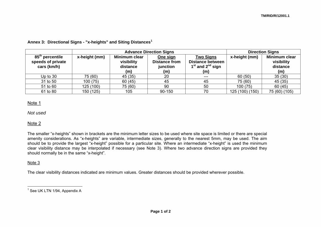
Annex 3: Directional Signs - "x-heights" and Siting Distances1
Advance Direction Signs Direction Signs
85th percentile speeds of private
cars (km/h)
x-height (mm) Minimum clear visibility distance
(m)
One sign Distance from
junction (m)
Two Signs Distance between
1st and 2nd sign (m)
x-height (mm) Minimum clear visibility distance
(m) Up to 30 75 (60) 45 (35) 20 --- 60 (50) 35 (30) 31 to 50 100 (75) 60 (45) 45 45 75 (60) 45 (35) 51 to 60 125 (100) 75 (60) 90 50 100 (75) 60 (45) 61 to 80 150 (125) 105 90-150 70 125 (100) (150) 75 (60) (105)
Note 1
Not used Note 2 The smaller “x-heights” shown in brackets are the minimum letter sizes to be used where site space is limited or there are special amenity considerations. As “x-heights” are variable, intermediate sizes, generally to the nearest 5mm, may be used. The aim should be to provide the largest “x-height” possible for a particular site. Where an intermediate “x-height” is used the minimum clear visibility distance may be interpolated if necessary (see Note 3). Where two advance direction signs are provided they should normally be in the same “x-height”. Note 3 The clear visibility distances indicated are minimum values. Greater distances should be provided wherever possible.
1 See UK LTN 1/94, Appendix A
Page 1 of 2

TM/RID/R/12001.1
Note 4 For speed between 61 to 80 km/h the larger bracketed sizes are for direction signs located on the noses of diverging lanes. Note 5 Not used Note 6 The dimensions in this table apply to all types of legend. Note 7 In the “One Sign” and “Two Sign” Advance Sign the distances shown are for guidance only and are not to be taken as being precise. In certain circumstances where one or more signs are provided it may be appropriate to increase the distances given; e.g. on an urban road where the advance direction sign shows destinations associated with dedicated lanes that commence well before the junction. Where two signs are provided, the second sign should be sited in accordance with the “One Sign” column. Note 8 Where two junctions are closer together than the siting distance plus visibility distance they should generally be signed as one junction.
Page 2 of 2

TM/RID/R/1200.1
Annex 4a: Placement of Characters on Virtual "Tiles" as in UK TSM7, Figure 2-1
Page 1 of 1

Annex 4b: Horizontal Spacing of Sign Elements as in UK TSM3, Figure 2-2
TM/RID/R/1200.1
Annex 4c: Abbreviated Place-names and Spacings
Page 1 of 1

TM/RID/R/1200.1
Annex 4D: Tile (Virtual) Widths
Page 1 of 1