process analytics in ethylene production plants · trol, product quality, and plant safety....
TRANSCRIPT

Ethylen is the largest volume industri-ally produced organic material and its majority is used in the production of polymers and derivatives. Between a variety of processes the thermal crack-ing of hydrocarbons in the presence of steam (steam cracker) is mostly used. Regardless of the process type, all plants require process analytical equipment to collect reliable and accurate process data for process con-trol, product quality, and plant safety.
Siemens, a leader in process analyti-cal instrumentation, has proven over decades its capability to plan, engi-neer, manufacture, implement and service analyzer systems for use in ethylen plants worldwide. This Case Study provides an overview of the steam cracking process and describes how Siemens, with its out-standing analyzer technology, appli-cation know-how and system integra-tion expertise can provide remarkable user benefits.
EthyleneEthylene is the largest volume industrially produced organic mate-rial. Current worldwide production is about 95 Mio. t/year and is pro-jected to increase for the foresee-able future. A typical modern plant produces in excess of 800000 t/year. Feedstock to ethylene plants ranges from light Ethane/Propane mix to heavy naphta and vacuum gas oils. Most plants are designed with raw material flexibility in mind. Majority of ethylene produced is used in the production of polymers and ethyl-ene derivatives such as ethylene oxide and glycol. A typical ethylene plant also makes a number of other important chemicals such as propy-lene, butadiene and pyrolysis gaso-line.
In the past years, Ethylene plants have evolved into highly integrated, highly flexible processing systems that can profitably adjust to chang-ing raw material availability and market demands for Olefins prod-ucts. Advanced process control technologies are used in Olefins plants and have greatly improved products qualiy, plant efficiency and resulted in quick payback of the investment.
Typical process features of an ethyl-ene process are short residence time in the furnace, high selectivity, feed-stock flexibility, operational reliabil-ity and safety, easy start-up, and energy efficiency.
Process analytics is a key issue for process control by online monitor-ing the various process streams in ethylene and propylene production. Process analytics maximizes yields and ensures product quality specifi-cations.
Process Analytics inEthylene Production Plants
Ca
se S
tud
y ·
De
cem
be
r 2
00
7
© Siemens AG 2007
2
Ethylene production overview
Ethylene Ethylene, H2C=CH2, is the lightest ole-fin. It is a colorless, flammable gas, which is produced mainly from petro-leum-based feedstocks by thermal cracking in the presence of steam.Ethylene has almost no direct enduses but acts almost exclusively as an inter-mediate in the manufacture of other chemicals, especially plastics.
Ethylene may be polymerized directly to produce polyethylene, the world's most widely used plastic. Ethylene can also be chlorinated to produce 1,2-dichloro-ethane, a precursor to the plastic polyvi-nyl chloride, or combined with benzene to produce ethylbenzene, which is used in the manufacture of polystyrene, another important plastic. Smaller amounts of ethylene are oxidized to produce chemicals including ethylene oxide, ethanol, and polyvinyl acetate.
Ethylen quality depends on users requirements in downstream processes. No single chemicalgrade ethylen exists, but ethylene content normally exceeds 99,7%. Sulfur, oxygen, acetylene, hydrogen, carbon monoxide and car-bon dioxide are the most troublesome impurities that must be controlled care-fully.
Raw materialsVarious feedstocks (liquid and gaseous) are used for the production of ethylen. The principal feedstocks are naphtas, a mixture of hydrocarbons in the boiling range of 30 to 200 °C. Depending on the origin, naphta composition and quality can vary over a wide range requiring quality control of the feed mixtures. Preferably in the US and the middle east light feedstocks (natural gas, ethane, propane, butan) are used. Gas oils (crude oil fractions) are also gaining importance as feedstocks in some areas of the world.
Chemical analysis of the feedstock is important to ensure the required prod-uct specification and even more when the production is based on varying feed-stocks.
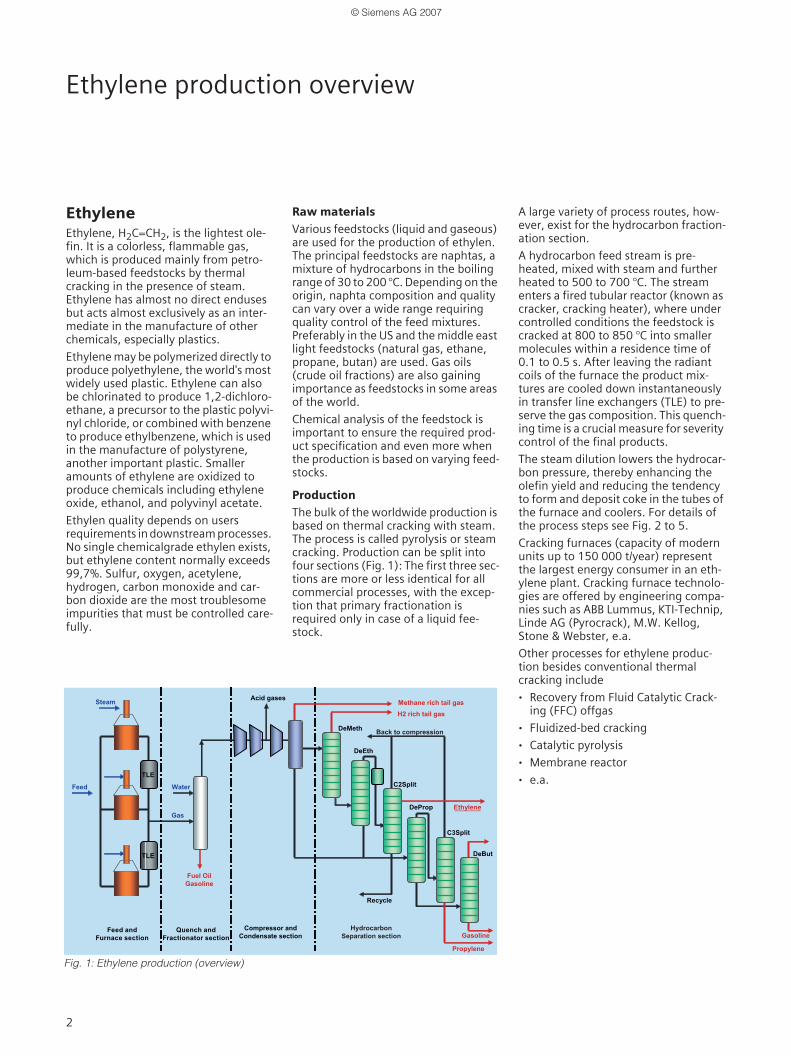
ProductionThe bulk of the worldwide production is based on thermal cracking with steam. The process is called pyrolysis or steam cracking. Production can be split into four sections (Fig. 1): The first three sec-tions are more or less identical for all commercial processes, with the excep-tion that primary fractionation is required only in case of a liquid fee-stock.
A large variety of process routes, how-ever, exist for the hydrocarbon fraction-ation section.
A hydrocarbon feed stream is pre-heated, mixed with steam and further heated to 500 to 700 °C. The stream enters a fired tubular reactor (known as cracker, cracking heater), where under controlled conditions the feedstock is cracked at 800 to 850 °C into smaller molecules within a residence time of 0.1 to 0.5 s. After leaving the radiant coils of the furnace the product mix-tures are cooled down instantaneously in transfer line exchangers (TLE) to pre-serve the gas composition. This quench-ing time is a crucial measure for severity control of the final products.
The steam dilution lowers the hydrocar-bon pressure, thereby enhancing the olefin yield and reducing the tendency to form and deposit coke in the tubes of the furnace and coolers. For details of the process steps see Fig. 2 to 5.
Cracking furnaces (capacity of modern units up to 150 000 t/year) represent the largest energy consumer in an eth-ylene plant. Cracking furnace technolo-gies are offered by engineering compa-nies such as ABB Lummus, KTI-Technip, Linde AG (Pyrocrack), M.W. Kellog, Stone & Webster, e.a.
Other processes for ethylene produc-tion besides conventional thermal cracking include
· Recovery from Fluid Catalytic Crack-ing (FFC) offgas
· Fluidized-bed cracking
· Catalytic pyrolysis
· Membrane reactor
· e.a.Feed
Steam
Water
Acid gases
Gas
TLE
TLE
Recycle
Ethylene
DeMeth
DeEth
C2Split
C3Split
DeBut
Propylene
DeProp
Gasoline
Methane rich tail gasH2 rich tail gas
Feed and Furnace section
Quench and Fractionator section
Fuel Oil Gasoline
Back to compression
Compressor andCondensate section
Hydrocarbon Separation section
Fig. 1: Ethylene production (overview)
© Siemens AG 2007

3
Ethylene production
Feed Cracking
Pyrolysis furnace The hydrocarbon molecules of the feed-stock are cracked in the furnace (Fig. 2) in the presence of a catalyst at high temperatures. Typically more than ten furnaces are used in a single ethylene plant. Most feedstocks are naphta or a mixture of ethane and methane. The feed is mixed (diluted) with steam to minimize the side reaction of forming coke and to improve selectivity to pro-duce the desired olefines by lowering hydrocarbon partial pressure. Cracking is an endothermic reaction with heat supplied by side-wall or floor burners or a combination of both, which use gas-eous and/or liquid fuels.The fundamental parameters of crack-ing furnaces are temperature and tem-perature profile, residence time of the gas during cracking, and partial pres-sure.
Tranfer Line ExchangerThe reaction mixture exiting the radiant coil of the furnace contains a large spec-trum of hydrocarbons. It is instanta-neously cooled in quench coolers called transfer line exchangers (Fig. 2) to pre-serve the gas composition. Valuable high pressure steam is generated from the cracked gas during this process.
Cracked Gas Processing Further processing of cracked gas, i.e. separation into the desired products or fractions, can be performed in many dif-ferent sequences that depend on the feedstock type and the number and specification of the plant products. Many options are available with differ-ent plant designs for cracked gas derived from gaseous or liquid fee-stocks. For example: With pure ethane as feedstock, the amount of C3 and heavier byproducts is small and their recovery is not economically feasible, or a significant content of propane in the feedstock makes a depropanizer neces-sary and butane feeds requires oil and gasoline removal from the cracked gas.
Therefore, plants will differ from each other and the following flow diagrams of show only exemplary solutions!
Spaltofen
1.1 1.2
1.3
1.5
1.6
1.7 1.8
1.4
1.1 1.2
1.3
1.5
1.6
1.7 1.8
1.4
Flue gas Flue gas
Steam boiler
Diluent steam
Freshfeed
Recyclefeed Fuel
to quench tower
Furnace
Transfer lineexchanger
Fig. 2: Feed and furnace section
Sampling point Sampling stream
Measuring Component
Measuring Range
Measuring Task
Analyzer
1.1 Fresh feed C1, C2, C3, C4+ (PINA)
% range Feed composition
MAXUM
1.2 Mixed feed(Fresh + recycle)
C1, C2=, C2 C3, C4+
% range Feed composition
MAXUM orMicroSAM
1.3 Fuel gas to furnaces N2, H2, C1, C2=∞
% range BTU firing rate control
MAXUM orMicroSAMULTRAMAT 6
1.4 Furnace convection section
O2 0 ... 8 % Cracking control
ZrO2 probe
1.5 Cracked gas at TLE exit CONO (NO2)O2
0 ... 200 ppm0 ... 250 ppm0 ... 8 ppm
Cracking control
ULTRAMAT 23ULTRAMAT 23 OXYMAT 64
1.6 Boiler combustion control
O2 0 ... 10 % ZrO2 probe
1.7 Stack of steam boiler
CONOxO2
0 ... 0,5 %0 ... 0,1 %0 ... 10 %
Emission control
ULTRAMAT 6ULTRAMAT 23OXYMAT 6
1.8 Flue gas from furnace
CONOx, SO2O2
In compli-ance with regulations
Emission control
ULTRAMAT 6ULTRAMAT 23OXYMAT 6
Table 1: Process analysis data (selection) in the feed and furnace section
© Siemens AG 2007

4
Gasoline FractionatorHeavy fuel oils cuts are separated from the bulk of the effluent stream in the gasoline fractionator (Fig. 3) by direct contact with circulating pyrolysis oil. Function is to make a sharp separation between the heavy oil fraction from the gasoline and lighter fractions .The gasoline fractionator is only used in case of a liquid feedstock (naphta).
Quench towerFurther cooling is performed in the quench tower (Fig. 3) by circulating water streams to minimize any further cracking. The quench tower operates as a partial condenser for the fractionator, condensing practically all of the steam and most of the pyrolysis gasoline com-ponents. In some designs, the gasoline fractionator and the quench tower are combined into one single structure.
Compression trainThe gas from the quench tower is then compressed in a 4 or 5 stage compres-sor train (Fig. 4) to an optimum pres-sure for separating it into various com-ponents. Water and hydrocarbons are separated between stages and recycled. Acid gases (CO2 and H2S) are removed after the 3rd or 4th compression stage by scrubbing them with a dilute causic soda solution. In case of higher sulfur content a separate gas removal system is used.
Refrigeration trainThe pyrolysis gas is then partially con-densed over the stages of a refrigera-tion system to about -165 °C, where only the hydrogen remains in the vapor stage. The stage condensates are fed to the demethanizer while hydrogen is withdrawn from the lowest tempera-ture separator.
DemethanizerThe DeMethanizer is designed for com-plete separation of methane from ethyl-ene and heavier components. The DeMethanizer overhead consists of methane with some impurities of hydrogen, CO and traces of ethylene. The DeMethanizer bottoms, consisting of ethylene and heavier components, are sent to the DeEthanizer.
DeethanizerThe DeEthanizer produces C2 hydrocar-bons as overhead (acetylene, ethane and ethylene) and C3 and heavier hydrocarbons as bottoms.
3.33.1
3.2
3.33.1
3.2
cracked gas from quench section
Compression Stages 1 - 4
Compression Stage 5
Dryer and cooler
to DeMethanizer
to DePropanizer
Hydrogen rich tail gas
Acid gases to incineration or
recovery
Acid gas scubber
2.12.1
Gasoline fractionation
Water quench
Gasoline stripping
from TLE (liquid feedstock)
Oil quench
Pyrolysis fuel oil Pyrolysis gasoline
to compression section
Fig. 3: Fractionation and quench section Fig. 4: Compression section
Sampling point Sampling stream
Component Measuring Range
Measuring Task
Analyzer
2.1 Cracked gas at quench inlet
H2C1, C2= C2 ,C3=, C3, C4+
0 ... 40 %% range % range
Cracked gas composition
MAXUM or MicroSAMCALOMAT 6
3.1 Cracked gas after caustic scrubber
CO2CO
0 ... 5 ppm0 ... 5000 ppm
Process control MAXUMULTRAMAT 6
3.2 Drying/Chilling outlet(to Methanizer)
COC2=
0 ... 3000 ppm0 ... 1/5 %
Process control ULTRAMAT 6MAXUM or MicroSAM
3.3 Drying/Chilling outlet (Hydrogen rich tail gas)
N2, H2, C1, C2=, C2, CO
% range Product quality control
MAXUM or MicroSAMULTRAMAT 6
Table 2: Process analysis data (selection) in the quench and compression section
© Siemens AG 2007

5
Acetylene hydrogenationThe DeEthanizer overhead is heated and hydrogen is added to convert acetylene to ethylene and ethane (hyrogenation). The effluent contains less than 1 ppm of acetylene, and traces of methane and hydrogen.
Ethylene fractionator (C2 splitter) After acethylene removal, the dried gas enters an ethylene-ethane separator (ethylene fractionator or C2 splitter). Ethylene product is gained here while ethane being recycled.
DePropanizerThe condensate stripper and the DeEth-anizer bottoms are both processed in the DePropanizer for a sharp separation of C3 hydrocarbons as overheads and C4+ as bottoms.
Propylene fractionator (C3 splitter)The overhead of the DePropanizer is sent to the propylene fractionator (C3 splitter) for further processing.
DeButanizerThe DePropanizer bottoms are further processed in the DeButanizer for sepa-ration of C4 product from light gasoline.
Recycle
DeMethanizer
DeEthanizer
C2Split
DePropanizer
DeButanizer
Benzin
Hydrierung
Recycle
Propylen
4.7
4.5
4.4
4.3
4.2
4.11
4.9
4.8
4.10
4.6
C3+
C5+
C4+
C4
C3
C2
Cold box PSA
4.1
PSA: Pressure Swing Adsorption Unit
4.7
4.5
4.4
4.3
4.2
4.11
4.9
4.8
4.10
4.6
C3+
C5+
C4+
C4
C3
C2
4.1from refrigeration
from refrigeration
from refrigeration
H2 rich tail gas
Methane rich tail gas
Ethylene
C4 material
Gasoline
Propylene
DeMethanizer
DeEthanizerRecycle
Recycle
Hydrogenation
C2Split
C3Split
DePropanizer
DeButanizer
Cold box PSA
Fig. 5: Hydrocarbon separation section
Sampling point Sampling stream
Component Measuring Range Measuring Task Analyzer
4.1 Hydrogen rich tailgas H2, N2, C1, C2=, C2, CO % range Tail gas ccomposition MAXUM or MicroSAM
4.2 Methane rich tailgas H2, N2, C1, C2=, C2, CO % range Tal gas composition MAXUM or MicroSAM
4.3 DeMethanizer bottoms C2/C3= % range Process control MAXUM or MicroSAM
4.4 DeEthanizer bottoms C2/C3= % range Process control MAXUM or MicroSAM
4.5 DeEthanizer overhead C3=/C2 ppm Process control MAXUM or MicroSAM
4.6 C2 split bottoms C2=, C3= % range Process control MAXUM or MicroSAM
4.7 Ethylene product C1, C2, C2=CO, CO2, NH3MeOH, PrOH, Carbonyl
0 ... 300/10/1000 ppm0 ...2/5/1 ppm0 ... 1 ppm
Product quality MAXUMMAXUMMAXUM ULTRAMAT 6
4.8 To DeButanizer C1, C2, C2=CO, CO2, NH3MeOH, PrOH, Carbonyl
0 ... 1000/10/1000 ppm0 ... 2/5/1 ppm0 ... 1 ppm
Process control MAXUMMAXUMMAXUM
4.9 DePropanizer overhead C2, C3=, C3, C4+ % range Process control MAXUM or MicroSAM
4.10 C3 split bottomsPropylene product
C3=, C4+, Propadiene (PD), Propine (MA)
% range Product quality MAXUMULTRAMAT 6
4.11 Buten-1 product C2,C2=, C4, C4=, C6= 0 ... 500/100/3000 ppm Process control MAXUM or MicroSAM
Table 3: Process analysis data (selection) in the hydrocarbon separation section
© Siemens AG 2007

6
Process analyzer application
Process optimizationProcess optimization is critical for ethyl-ene production because cracking reac-tions change as the run proceeds. Oper-ation costs are high and , therefore, process control including online analyz-ers providing almost realtime process information has reached a very high level of importance. Models for differ-ent kinds of feedstocks have been developped to optimize production of certain amounts of ethylen, propylene and other products at maximum profit even with changing of feedstock quality or type.
Process analyzer tasks Process analytical equipment is an in-dispensable part of any ethylene plant because it provides the operator and the control system with key data from the process and its environment.
Four major applications
Analyzer applications can be divided in four groups depending on how and where the analyzer data are used:
· Closed-loop control for process and product optimization This application helps to increase yield, reduce energy consumption, achieve smooth operation, and keep product quality accoding to the speci-fication
· Quality control and documentationfor ISO compliance
· Plant monitoring and alarmsThis application protects personnel and plant from possible hazard from toxic or explosive substances
· Environmental control This application helps to keep air and water emission levels in compliance with official regulations.
Analyzers and sampling pointsMore than 100 analyzers of different type are used in an ethylene plant rang-ing from simple sensor type monitors to high technology process gas chromato-graphs.
The list typically includes
· Process gas chromatographs
· Continuous gas analyzers (paramagnetic oxygen analyzers, NDIR analyzers, total hydrocarbon content analyzers)
· Analyzers for moisture and O2 traces
· Low Explosion Level (LEL) analyzers
· Liquid analyzers for pH, conductivity, etc.
Analyzer installations
Analyzers are installed partially in the field close to the sampling location and/or in an analyzer house (shelter). In modern plants most of the analyzers are interfaced to a plant wide data com-munication system for direct data trans-fer from and to the analyzers. The total number of analyzers installed in a plant varies from plant to plant depending on the type of process, indi-vidual plant conditions and user requirements.
Safety and environmental impactsEthylene plants require special mea-sures for protection of personnel and the environment. Despite of national regulations, the following measures are considered as standard worldwide for any plant:
· Flue gas emission controlNOx emissions are limited by use of LowNOx burners and/or integrated SCR technology for catalytic reduc-tion. NOx limits are, in some regions, down to < 50 ppm.
· Particulate emission during the decoking process is reduced by either incineration or appropriate filter tech-nology.
· Fugitive emissions and VOC control
· Explosion protectionAreas where inflammable substances in sufficient quantity can get in con-tact to oxygen (air) become a hazard-ous area. In this case, measures are necessary to exclude the danger of ignition.
· Water protectionLiquid emission of the plant mainly results from quench water, dilution steam, caustic-stripping (acid gas removal) liquid and decoking water. These streams are treated properly before beeing fed to the wastewater plant.
· Waste disposalAn ethylene plant produces a variety of waste materials that have to be treated according to the relevant reg-ulations for disposal.
LEL Analyzers Mixtures of combustible substances and air or oxygen are explosive in certain concentration ranges. For each concen-tration mixture, low (LEL) and high (HEL) explosion limits are specified that depend on the temperature and pres-sure of the gas. Special gas detectors are used to monitor substances such as hydrogen, ethylene, propylene, CO and O2 to prevent the atmosphere inside or outside the analyzer house from reach-ing the LEL. Gas detectors are typically part of the safeguarding system of the analyzer house to minimize the exposure of per-sonnel to flammable or toxic hazads.
Associated operationsA number of associated plant units and processes with the need of using pro-cess analyzers are required to run an ethylene plant, including e.g.
· Furnace decoking
· Flue gas emission control
· Flue gas cleaning
· Air separation
· Waste water treatment
· Waste incineration
· Explosion warning
© Siemens AG 2007

7
Siemens Process Analytics at a glanceProducts
Siemens Process AnalyticsSiemens Process Analytics is a leading provider of process analyzers and pro-cess analysis systems. We offer our glo-bal customers the best solutions for their applications based on innovative analysis technologies, customized sys-tem engineering, sound knowledge of customer applications and professional support. And with Totally Integrated Automation (TIA). Siemens Process Analytics is your qualified partner for efficient solutions that integrate pro-cess analysers into automations sys-tems in the process industry.
From demanding analysis tasks in the chemical, oil & gas and petrochemical industry to combustion control in power plants to emission monitoring at waste incineration plants, the highly accurate and reliable Siemens gas chro-matographs and continuous analysers will always do the job.
Siemens process Analytics offers a wide and innovative portfolio designed to meet all user requirements for compre-hensive products and solutions.
Our ProductsThe product line of Siemens Process Analytics comprises extractive and in-situ continuous gas analyzers (fig. 6 to 9), process gas chromatographs (fig. 10 to 13), sampling systems and auxiliary equipment. Analyzers and chromato-graphs are available in different ver-sions for rack or field mounting, explo-sion protection, corrosion resistant etc.
A flexible networking concept allows interfacing to DCS and maintenance stations via 4 to 20 mA, PROFIBUS,Modbus, OPC or industrial ethernet.
Fig. 6: Series 6 gas analyzer (rack design)
Fig. 7: Product scope „Siemens Continuous Gas Analyzers“
Extractive Continuous Gas Analyzers (CGA)ULTRAMAT 23 The ULTRAMAT 23 is a cost-effective multicomponent analyser for the
measurement of up to 3 infrared sensitive gases (NDIR principle) plusoxygen (electrochemical cell). The ULTRAMAT 23 is suitable for a wide range of standard applications. Calibration using ambient air eliminates the need of expensive calibration gases.
CALOMAT 6/62 The CALOMAT 6 uses the thermal conductivity detection (TCD) method to measure the concentration of certain process gases, preferably hydro-gen.The CALOMAT 62 applies the TCD method as well and is speciallydesigned for use in application with corrosive gases such as chlorine.
OXYMAT 6/61/64 The OXYMAT 6 uses the paramagnetic measuring method and can be used in applications for process control, emission monitoring and quality assurance. Due to its ultrafast response, the OXYMAT 6 is perfect for monitoring safety-relevant plants. The corrosion-proof design allows analysis in the presence of highly corrosive gases.The OXYMAT 61 is a low-cost oxygen analyser for standard applications.The OXYMAT 64 is a gas analyzer based on ZrO2 technology to measure smallest oxygen concentrations in pure gas applications.
ULTRAMAT 6 The ULTRAMAT 6 uses the NDIR measuring principle and can be used in all applications from emission monitoring to process control even in the presence of highly corrosive gases.ULTRAMAT 6 is able to measure up to 4 infrared sensitive components in a single unit.
ULTRAMAT 6 /OXYMAT 6
Both analyzer benches can be combined in one housing to form a multi-component device for measuring up to two IR components and oxygen.
FIDAMAT 6 The FIDAMAT 6 measures the total hydrocarbon content in air or even in high-boiling gas mixtures. It covers nearly all requirements, from trace hydrocarbon detection in pure gases to measurement of high hydrocar-bon concentrations, even in the presence of corrosive gases.
In-situ Continuous Gas Analyzer (CGA)LDS 6 LDS 6 is a high-performance in-situ process gas analyser. The measure-
ment (through the sensor) occurs directly in the process stream,no extractive sample line is required. The central unit is separated from the sensor by using fiber optics. Measurements are carried out in real-time. This enables a pro-active control of dynamic processes and allows fast, cost-saving corrections.
Fig. 8: Series 6 gas analyzer (field design) Fig. 9: LDS 6 in-situ laser gas analyzer
© Siemens AG 2007

8
Siemens Process Analytics at a glanceProducts (continued) and Solutions
Fig. 10: MAXUM edition II Process GC
Fig. 11: MicroSAM Process GC
Fig. 12: SITRANS CV Natural Gas Analyzer
Our solutionsAnalytical solutions are always driven by the customer´s requirements. We offer an integrated design covering all steps from sampling point and sample preparation up to complete analyser cabinets or for installation in analyser shelters (fig. 14). This includes also sig-nal processing and communications to the control room and process control system.
We rely on many years of world-wide experience in process automation and engineering and a collection of special-ized knowledge in key industries and industrial sectors. We provide Siemens quality from a single source with a func-tion warranty for the entire system.
Read more in "Our Services“.
Fig. 14: Analyzer house (shelter)
Process Gas Chromatographs (Process GC) MAXUM edition II MAXUM edition II is very well suited to be used in rough industrial envi-
ronments and performs a wide range of duties in the chemical and pet-rochemical industries and refineries.MAXUM II features e. g. a flexible, energy saving single or dual oven con-cept, valveless sampling and column switching, and parallel chromatog-raphy using multiple single trains as well as a wide range of detectors such as TCD, FID, FPD, PDHID, PDECD and PDPID.
MicroSAM MicroSAM is a very compact explosion-proof micro process chromato-graph. Using silicon-based micromechanical components it combines miniaturization with increased performance at the same time.MicroSAM is easy to use and its rugged and small design allows mount-ing right at the sampling point. MicroSAM features drastically reduced cycle times, provides valveless sample injection and column switching and saves installation, maintenance, and service costs.
SITRANS CV SITRANS CV is a micro process gas chromatograph especially designed for reliable, exact and fast analysis of natural gas. The rugged and com-pact design makes SITRANS CV suitable for extreme areas of use, e.g. off-shore exploration or direct mounting on a pipeline.The special software "CV Control" meets the requirements of the natural gas market, e.g. custody transfer.
Fig. 13: Product scope „Siemens Process Gas Chromatographs“
© Siemens AG 2007

9
Siemens Process Analytics at a glanceSolutions (continued) and Services
Our solutions ...
Analyzer networking fordata communication Engineering and manufacturing of pro-cess analytical solutions increasingly comprises "networking". It is getting a standard requirement in the process industry to connect analyzers andanalyzer systems to a communication network to provide for continuous and direct data transfer from and to the analysers.The two objectives are (fig. 16):
· To integrate the analyzer andanalyzer systems seamless into the PCS / DCS system of the plantand
· To allow direct access to the analyzers or systems from a maintenancestation to ensure correct and reliable operation including preventive orpredictive maintenance (fig.15).
Siemens Process Analytics provides net-working solutions to meet the demands of both objectives.
Our ServicesSiemens Process Analytics is your com-petent and reliable partner world wide for Service, Support and Consulting.
Our rescources for that are
· ExpertiseAs a manufacturer of a broad variety of analyzers, we are very much expe-rienced in engineering and manufac-turing of analytical systems and analyzer houses.We are familiar with communication networks, well trained in service and maintenance and familiar with many industrial pro cesses and industries.Thus, Siemens Process Analytics owns a unique blend of overall analytical expertise and experience.
· Global presenceWith our strategically located centers of competence in Germany, USA,Singapore, Dubai and Shanghai, we are globally present and acquainted with all respective local and regional requirements, codes and standards.All centers are networked together.
Fig. 16: Networking for DCS integration and maintenance support
Fig. 17: Portfolio of services
Fig. 15: Communication technologies
© Siemens AG 2007

10
Siemens Process Analytics at a glanceServices, continued
Our Services ...
Service portfolio Our wide portfolio of services is seg-mented into Consulting, Support and Service (fig. 17 to 18). It comprises really all measures, actions and advises that may be required by our clients throughout the entire lifecycle of their plant. It ranges from site survey to installation check, from instruction of plant personnel to spare part stock man-agement and from FEED for Process Analytics (see below) to internet-based service Hotline.
Our service and support portfolio (including third-party equipment) com-prises for example:
· Installation check
· Functionality tests
· Site acceptance test
· Instruction of plant personnel on site
· Preventive maintenance
· On site repair
· Remote fault clearance
· Spare part stock evaluation
· Spare part management
· Professional training center
· Process optimisation
· Internet-based hotline
· FEED for Process Analytics
· Technical consullting
FEED for Process AnalyticsFront End Engineering and Design (FEED) is part of the planning and engi-neering phase of a plant construction or modification project and is done after conceptual business planning and prior to detail design. During the FEED phase, best opportunities exist for costs and time savings for the project, as during this phase most of the entire costs are defined and changes have least impact to the project. Siemens Process Analyt-ics holds a unique blend of expertise in analytical technologies, applications and in providing complete analytical solutions to many industries.
Based on its expertise in analytical tech-nology, application and engineering , Siemens Process Analytics offer a wide scope of FEED services focused on anal-ysing principles, sampling technologies, application solutions as well as commu-nication system and given standards (all related to analytics) to support our cli-ents in maximizing performance and efficiency of their projects.
Whether you are plant operators or belong to an EPC Contractor you will benefit in various ways from FEED for Process Analytics by Siemens:
· Analytics and industry know how available, right from the beginning of the project
· Superior analyzer system perfor-mance with high availability
· Established studies, that lead to realistic investment decisions
· Fast and clear design of the analyzer system specifications, drawings and documentation
· Little project management and coordination effort, due to one responsible contact person and less time involvement
· Additional expertise on demand, without having the costs, the effort and the risks of building up the capac-ities
· Lowest possible Total Costs of Owner-ship (TCO) along the lifecycle regard-ing investment costs, consumptions, utilities supply and maintenance.
Fig. 18: Portfolio of services provided by Siemens Process Analytics
© Siemens AG 2007
www.siemens.com/processanalytics © Siemens AG 2007Subject to change
Case Study
Siemens AGAutomation and DrivesSensors and CommunicationProcess Analytics76181 KARLSRUHEGERMANY
Siemens Process Analytics - Answers for industry
If you have any questions, please contact your local sales representative or any of the contact addresses below:
Siemens AGA&D SC PA, Process AnalyticsÖstliche Rheinbrückenstr. 5076187 KarlsruheGermany
Phone: +49 721 595 3829Fax: +49 721 595 6375E-mail:[email protected]/prozessanalytics
Siemens Ltd., ChinaA&D SC, Process Analytics7F, China Marine TowerNo.1 Pu Dong AvenueShanghai, 200120P.R.China
Phone: +86 21 3889 3602Fax: +86 21 3889 3264E-mail: [email protected]
Siemens Energy & Automation Inc.7101 Hollister RoadHouston, TX 77040USA
Phone: +1 713 939 7400Fax: +1 713 939 9050E-mail: [email protected]
www.siemens.com/processanalytics
Siemens LLCA&D 2B.PO Box 2154,Dubai, U.A.E.
Phone: +971 4 366 0159Fax: +971 4 3660019E-mail: [email protected]/processanalytics
Siemens Pte. LimitedA&D SC PS/PA CoC60 MacPherson RoadSingapore 348615
Phone: +65 6490 8728Fax: +65 6490 8729E-mail: [email protected]
www.siemens.com/processanalytics
© Siemens AG 2007