process vfd savings calculator user guide tool user... · controlled by primitive part-load ......
TRANSCRIPT

PROCESS VFD SAVINGS CALCULATOR USER GUIDE
ENERGY EFFICIENCY FOR BUSINESS CUSTOM INCENTIVES
CUSTOM-TO-GO
CONTENTS 1. Getting Started ......................................................................................................................... 2
2. Measure Tool Description ....................................................................................................... 2
2.1. Applicable Types of Equipment and size Covered by the Tool ....................................... 4
3. Measure Tool Use .................................................................................................................... 6
3.1. Select Your Service Territory .......................................................................................... 6
3.2. Tool Inputs ....................................................................................................................... 7
3.3. Tool Outputs – Savings Summary ................................................................................. 21
3.1. Tool Outputs – Notes and Error Messages..................................................................... 23

Duke Energy Progress EEB VFD Instructions
Page 2 of 25 Version 1.0.2 – 5/17/2016
1. GETTING STARTED
The current version of the Process Variable Frequency Drive (VFD) Savings Calculator can be
downloaded from http://duke-energy.com/EEBTools. It is included in the Energy Efficiency for
Business Custom-To-Go tool suite, which contains a number of useful tools that can help you
calculate savings and incentives for various energy saving measures.
The ZIP output file from the calculator must be submitted with the Energy Efficiency for
Business application (Step 1) in order to receive an incentive payment. For application
submissions and questions about the application process, contact us at CustomIncentives@duke-
energy.com.
2. MEASURE TOOL DESCRIPTION
Variable Speed Drives (VSD), also referred to as Variable Frequency Drives (VFD), are used for
controlling AC motors. The VFD is a solid-state device that controls the frequency and voltage
supplying the motor. Many AC motors used for process applications are oversized to
accommodate peak loads even though the average loads are lower. The most common
applications involve centrifugal pumps and fans which have large savings potential due to their
power versus speed curves. Without VFDs the motors are left operating at full speed or are
controlled by primitive part-load strategies. Often times the motors cannot be cycled on and off
too frequently so the motors remain at full speed. The VFD offers large energy savings for these
AC motors that operate at partial loads.
This tool was developed to assist customers in identifying and estimating VFD saving
opportunities on process pumps and fans.
Process VFD Calculator can be used for facilities with the characteristics shown in Table 1.
Table 1: EMS Savings Calculator Common Features
Description Measure Feature
States North Carolina
South Carolina
Locations All
Building Types Office
School K-12
College/University
Retail/Service
Restaurant
Hotel/Motel (Guest Rooms)
Hotel/Motel (Other)
Medical
Grocery
Warehouse
Light Industry
Heavy Industry

Duke Energy Progress EEB VFD Instructions
Version 1.0.2 – 5/17/2016 Page 3 of 25
Parking Garage
Operating Hours Monday – Friday, 8am – 5pm
Monday – Friday, 7am – 7pm
Monday – Friday, 6am – 10pm
Monday – Friday, 24 hours per day
Monday – Friday, 6am – 8pm, Saturday and Sunday, 8am – 6pm
Monday – Saturday, 8am – 5pm
Monday – Saturday, 10am – 9pm
Monday – Saturday, 7am – 7pm, Sunday, 8am – 5pm
Monday – Sunday, 8am – 5pm
Monday – Sunday, 9am – 9pm
Monday – Sunday, 11am – 11pm
Monday – Sunday, 6am – 10pm
Monday – Sunday, 24 hours per day
System Types
Fan
Pump

Duke Energy Progress EEB VFD Instructions
Page 4 of 25 Version 1.0.2 – 5/17/2016
2.1. Applicable Types of Equipment and size Covered by the Tool
Process VFD Calculator covers the pump and fan systems described in Table 2.
Table 2: Equipment Coverage Matrix
Description Type Control Type Drive Type
Centrifugal Fan Airfoil, SISW
Airfoil, DIDW
Backward Inclined
Backward Curved,
SISW
Backward Inclined
Backward Curved,
DIDW
Radial, SISW
Radial Tip, SISW
Forward Curved, SISW
Forward Curved, DIDW
Tubular
Industrial and
Commercial Air
Handling
Industrial and
Commercial Material
Handling
Industrial and
Commercial Long
Shavings
On/Off
Outlet Dampers
Inlet Vanes
Direct
V. Belt
Rubber Chain
Centrifugal
Exhaust Fan Centrifugal Exhaust
On/Off
Outlet Dampers
Direct
V. Belt
Rubber Chain
Axial Fan Vaneaxial
Tube Axial
Propeller
On/Off
Outlet Dampers
Direct
V. Belt
Rubber Chain
Axial Exhaust Fan Axial Exhaust
On/Off
Outlet Dampers
Direct
V. Belt
Rubber Chain
Centrifugal Pump End Suction ANSI/API
End Suction Slurry
End Suction Stock
End Suction Sewage
Large End Suction
API Double Suction
Multistage Boiler Feed
Axial
Double Suction
Vertical Turbine
On/Off
Throttling
Recirculating
N/A

Duke Energy Progress EEB VFD Instructions
Version 1.0.2 – 5/17/2016 Page 5 of 25
Positive
Displacement
Pump
N/A Recirculating
N/A

Duke Energy Progress EEB VFD Instructions
Page 6 of 25 Version 1.0.2 – 5/17/2016
3. MEASURE TOOL USE
3.1. Select Your Service Territory
In order to properly load the correct utility program the user must first select the service territory
associated with their account. To begin, select your state from the list presented in the Select
State dialog box.
If the State of Indiana, Kentucky, or Ohio is selected the application will open the appropriate
service territory version of the software.
If one of the Carolinas is selected the application needs a little more information. In these cases,
a Select Service Territory dialog box will appear. Please either enter the service address zip code
or select the Utility associated with the service account.
To return to the state selection dialog box click on the “Choose State” link.

Duke Energy Progress EEB VFD Instructions
Version 1.0.2 – 5/17/2016 Page 7 of 25
3.2. Tool Inputs
Tool inputs are done either by selecting predefined dropdown options or entering numerical values
as prompted by the tool.

Duke Energy Progress EEB VFD Instructions
Page 8 of 25 Version 1.0.2 – 5/17/2016
Inputs window is divided into tabs. Refer to tables below for input details.

Duke Energy Progress EEB VFD Instructions
Version 1.0.2 – 5/17/2016 Page 9 of 25
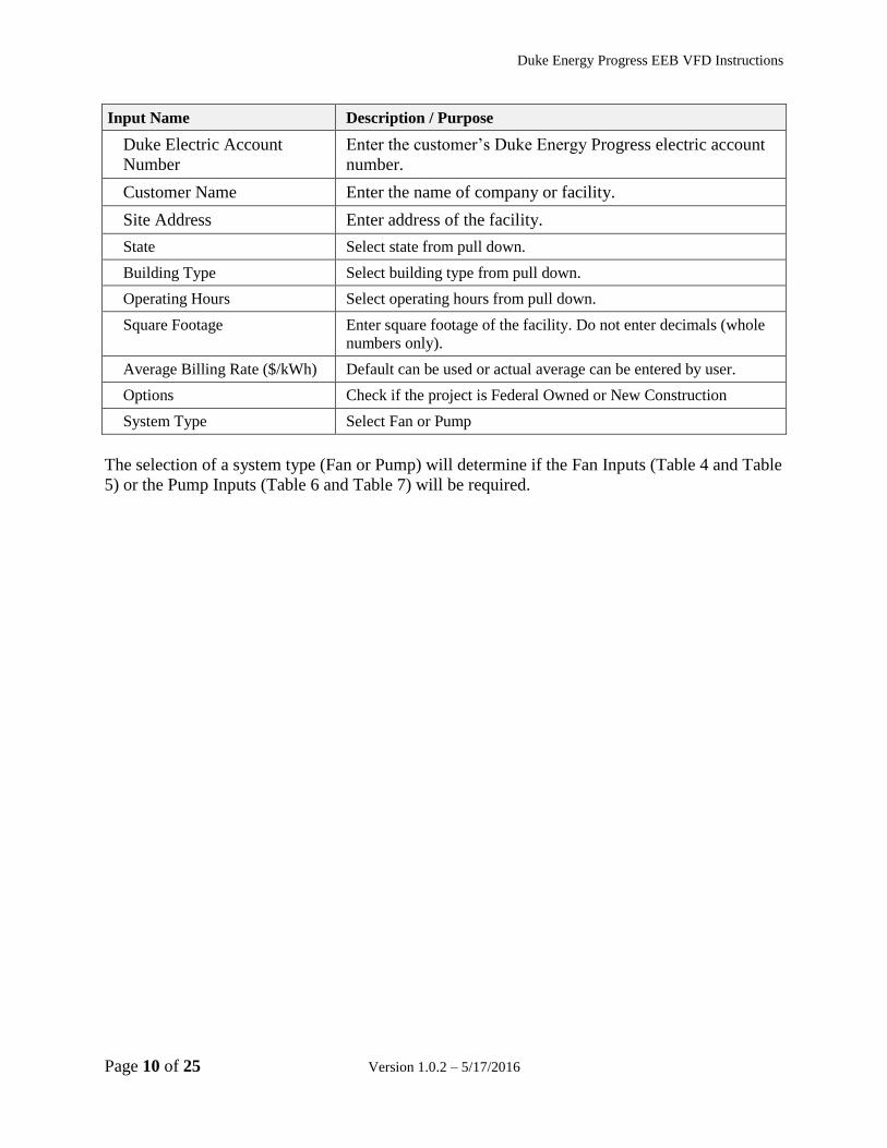
Table 2 – Site Inputs
Duke Energy Progress EEB VFD Instructions
Page 10 of 25 Version 1.0.2 – 5/17/2016
Input Name Description / Purpose
Duke Electric Account
Number
Enter the customer’s Duke Energy Progress electric account
number.
Customer Name Enter the name of company or facility.
Site Address Enter address of the facility.
State Select state from pull down.
Building Type Select building type from pull down.
Operating Hours Select operating hours from pull down.
Square Footage Enter square footage of the facility. Do not enter decimals (whole
numbers only).
Average Billing Rate ($/kWh) Default can be used or actual average can be entered by user.
Options Check if the project is Federal Owned or New Construction
System Type Select Fan or Pump
The selection of a system type (Fan or Pump) will determine if the Fan Inputs (Table 4 and Table
5) or the Pump Inputs (Table 6 and Table 7) will be required.
Duke Energy Progress EEB VFD Instructions
Version 1.0.2 – 5/17/2016 Page 11 of 25
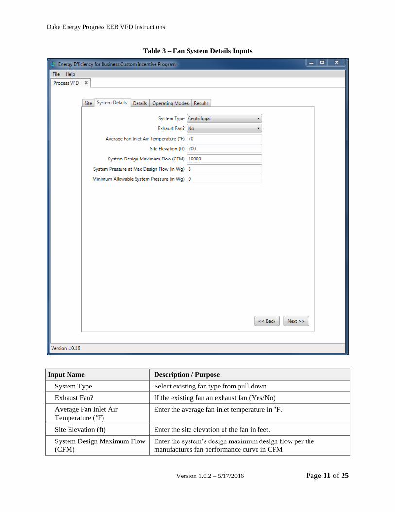
Table 3 – Fan System Details Inputs
Input Name Description / Purpose
System Type Select existing fan type from pull down
Exhaust Fan? If the existing fan an exhaust fan (Yes/No)
Average Fan Inlet Air
Temperature (°F)
Enter the average fan inlet temperature in °F.
Site Elevation (ft) Enter the site elevation of the fan in feet.
System Design Maximum Flow
(CFM) Enter the system’s design maximum design flow per the
manufactures fan performance curve in CFM

Duke Energy Progress EEB VFD Instructions
Page 12 of 25 Version 1.0.2 – 5/17/2016
System Pressure at Max Design
Flow (in Wg) Enter the system’s pressure at maximum design flow per the
manufactures fan performance curve in inches Wg.
Minimum Allowable System
Pressure (in Wg) If there is a minimum allowable operating pressure for the fan
system, enter it here. Otherwise, leave blank.
Duke Energy Progress EEB VFD Instructions
Version 1.0.2 – 5/17/2016 Page 13 of 25
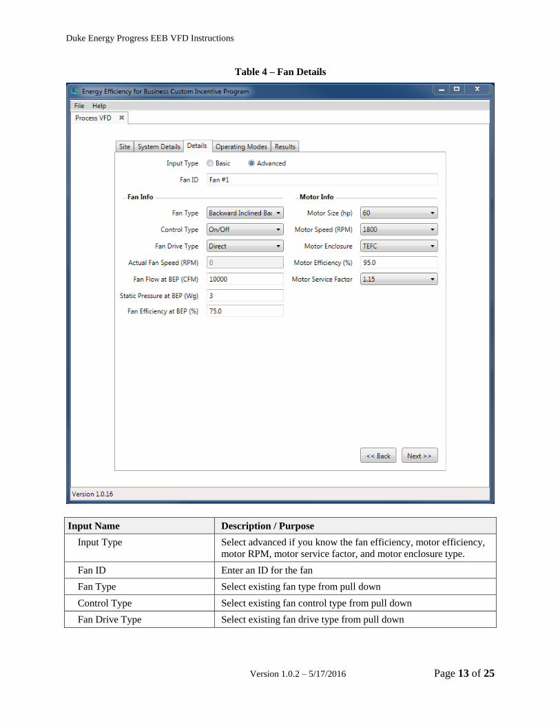
Table 4 – Fan Details
Input Name Description / Purpose
Input Type Select advanced if you know the fan efficiency, motor efficiency,
motor RPM, motor service factor, and motor enclosure type.
Fan ID Enter an ID for the fan
Fan Type Select existing fan type from pull down
Control Type Select existing fan control type from pull down
Fan Drive Type Select existing fan drive type from pull down

Duke Energy Progress EEB VFD Instructions
Page 14 of 25 Version 1.0.2 – 5/17/2016
Actual Fan Speed (RPM) Enter the actual fan speed when a belt drive has been specified.
This field is meant to account for differences in the motor and fan
gear ratios.
Fan Flow at BEP (CFM) Enter fan flow at the best efficiency point (BEP), as
specified by the manufacturer.
Static Pressure at BEP (in WG) Enter fan pressure at the best efficiency point (BEP), as specified
by the manufacturer.
Fan Efficiency at BEP (%) Enter maximum pump efficiency, as defined by the
manufacturer’s performance information.
Motor Size (hp) Select fan motor size in horse power, as specified by the
manufacturer.
Motor Speed Select fan motor speed in RPM, as specified by the manufacturer.
Motor Enclosure Select fan motor enclosure type, as specified by the manufacturer.
Motor Efficiency (%) Enter fan motor full load efficiency, as specified by the
manufacturer.
Motor Service Factor Select fan motor service factor, as specified by the manufacturer.
Duke Energy Progress EEB VFD Instructions
Version 1.0.2 – 5/17/2016 Page 15 of 25
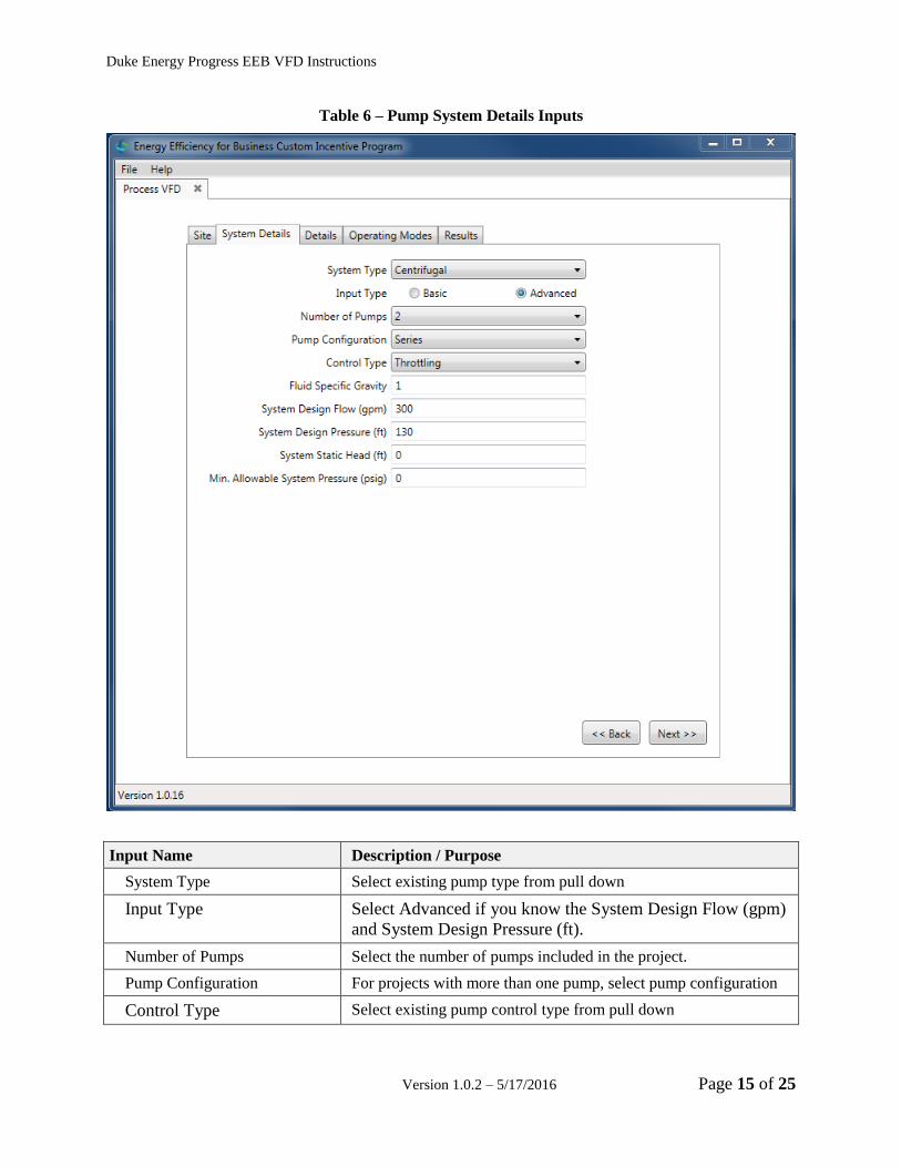
Table 6 – Pump System Details Inputs
Input Name Description / Purpose
System Type Select existing pump type from pull down
Input Type Select Advanced if you know the System Design Flow (gpm)
and System Design Pressure (ft).
Number of Pumps Select the number of pumps included in the project.
Pump Configuration For projects with more than one pump, select pump configuration
Control Type Select existing pump control type from pull down

Duke Energy Progress EEB VFD Instructions
Page 16 of 25 Version 1.0.2 – 5/17/2016
Fluid Specific Gravity Enter the specific gravity of the fluid being pumped.
Examples:
Water - 1.0
Seawater - 1.025
Gasoline - 0.7
Corn oil - 0.92
Milk - 1.03
Wine - 1.0
Beer - 1.0
Clarified sewage sludge - 1.1
Glycol Based Water Solution (25% @ 40F) - 1.048
To calculate specific gravity of slurry:
𝑆𝑚 =𝑆𝑙
1 + 𝐶𝑤 (𝑆𝑙𝑆𝑡− 1)
𝑆𝑚 = Specific gravity of mixture or slurry
𝑆𝑙 = Specific gravity of liquid phase
𝑆𝑡 = Specific gravity of solid phase
𝐶𝑤 = Concentration of solids by weight
System Design Flow (gpm) Enter system flow at design conditions (Centrifugal pumps only).
System Design Pressure (ft) Enter system pressure at design conditions (Centrifugal pumps
only).
System Static Head (ft) Enter system static head. Static head is the difference in height (ft)
between the source and destination of the pumped liquid. Closed
systems have a static head of zero feet.
Min. Allowable System
Pressure (psig)
If there is a minimum allowable operating pressure for the
pumping system, enter it here. Be sure to include static lift in the
minimum pressure value. Otherwise, leave blank.
The Pump Details tab includes the option to set all pumps identical or to provide pump details
for each pump. To enter pump details select a pump ID and press the “Edit Pump” button.

Duke Energy Progress EEB VFD Instructions
Version 1.0.2 – 5/17/2016 Page 17 of 25
This will open up the input screen detailed in Table 7.

Duke Energy Progress EEB VFD Instructions
Page 18 of 25 Version 1.0.2 – 5/17/2016
Table 7 – Pump Details
Input Name Description / Purpose
Input Type Select advanced if you know the pump efficiency, motor
efficiency, motor RPM, motor service factor, and motor enclosure
type.
Pump ID Enter an ID for the pump
Pump Type Select existing pump type from pull down
Pump Stages Select the number of stages in the pump.
Pump Flow at BEP (gpm) Enter pump flow at the best efficiency point (BEP), as
defined by the manufacturer's performance information (Centrifugal pumps only).
Pump Pressure at BEP (ft) Enter pump discharge pressure at the best efficiency point (BEP),
as defined by the manufacturer's performance information
(Centrifugal pumps only).
Pump Efficiency at BEP (%) Enter maximum pump efficiency, as defined by the
manufacturer's performance information. (Centrifugal pumps
only).
Motor Size (hp) Select fan motor size in horse power, as specified by the
manufacturer.
Motor Speed Select fan motor speed in RPM, as specified by the manufacturer.
Motor Enclosure Select fan motor enclosure type, as specified by the manufacturer.
Motor Efficiency (%) Enter fan motor full load efficiency, as specified by the
manufacturer.

Duke Energy Progress EEB VFD Instructions
Version 1.0.2 – 5/17/2016 Page 19 of 25
Motor Service Factor Select fan motor service factor, as specified by the manufacturer.
Table 8 – Operating Modes
Input Name Description / Purpose
Number of Operating Modes Select the number of operating modes for the equipment (fan or
pump).
VFD Peak Efficiency (%) Enter the peak efficiency of the proposed VFD, as specified
by the manufacturer.

Duke Energy Progress EEB VFD Instructions
Page 20 of 25 Version 1.0.2 – 5/17/2016
Minimum VFD Speed (%) Enter the minimum allowable VFD speed. Must be between
30% and 100%.
To edit the Operating Modes, select an Operating Mode and press the “Edit Operating Modes”
button. This will open up the input screen detailed in Table 9.
Table 9 – Operating Mode
Input Name Description / Purpose
Operating Mode Name Enter a name to identify the operating mode.
Annual Hours Enter the annual operating hours of the equipment (fan or pump).
Flow (GPM/CFM) Enter the flow required during the operating profile. CFM for fan
measures and GPM for pump measures.
Select Equipment Check equipment which operate during the operating mode.
Operating Period Select the operating period. If monthly, select the months
the equipment will operate.
Once all information is entered, select “Next” button on the bottom right corner of the Operating
Modes tab. The tool will then calculate savings based on the information entered and display the
results.
Duke Energy Progress EEB VFD Instructions
Version 1.0.2 – 5/17/2016 Page 21 of 25
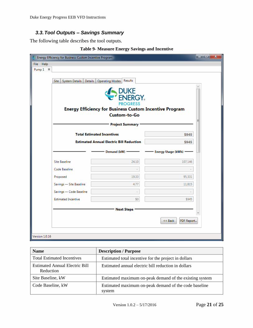
3.3. Tool Outputs – Savings Summary
The following table describes the tool outputs.
Table 9- Measure Energy Savings and Incentive
Name Description / Purpose
Total Estimated Incentives Estimated total incentive for the project in dollars
Estimated Annual Electric Bill
Reduction Estimated annual electric bill reduction in dollars
Site Baseline, kW Estimated maximum on-peak demand of the existing system
Code Baseline, kW Estimated maximum on-peak demand of the code baseline
system

Duke Energy Progress EEB VFD Instructions
Page 22 of 25 Version 1.0.2 – 5/17/2016
Proposed, kW Estimated maximum on-peak demand of the proposed system
Site Baseline, kWh Estimated energy use of the existing system
Code Baseline, kWh Estimated energy use of the code baseline system
Proposed, kWh Estimated energy use of the proposed system
Savings - Site Baseline, kW Estimated maximum on-peak demand savings for the measure
(difference between site baseline and proposed)
Savings - Site Baseline, kWh Estimated energy savings for the measure (difference between
site baseline and proposed)
Savings - Code Baseline, kW Estimated maximum on-peak demand savings for the measure
(difference between code baseline and proposed)
Savings - Code Baseline, kWh Estimated energy savings for the measure (difference between
code baseline and proposed)
Estimated Energy Use Incentive
($)
Estimated energy use incentive for the project in dollars

Duke Energy Progress EEB VFD Instructions
Version 1.0.2 – 5/17/2016 Page 23 of 25
3.1. Tool Outputs – Notes and Error Messages
While using the Process VFD Calculator, you may see one of the following error messages:
This indicates that you have not made a selection or entered an appropriate value in one or more
required fields. Please review your inputs and make sure that you have entered appropriate
values in the indicated input fields.
This indicates that the flow that you have entered for the current operating mode exceeds the
system design flow. Please reduce the flow for the current mode or review your input for the
system design flow.
This indicates that too many operating hours have been entered. The maximum number of hours
for all operating modes combined is 8,760. Please review your operating mode inputs.

Duke Energy Progress EEB VFD Instructions
Page 24 of 25 Version 1.0.2 – 5/17/2016
This indicates that the proposed retrofit qualifies for incentives through the prescriptive
incentives program. Measures that qualify through the prescriptive program cannot apply for
incentives through the custom incentives program (classic custom or custom-to-go).
This indicates that the proposed project exceeds the upper limit of the Custom-to-Go program
and is only eligible for incentives through the Classic Custom program. Please submit an
application to the Classic Custom program for this project.
This indicates that your project will result in negative savings and incentives. Please review your
measure inputs and ensure that all inputs are correct. You will not be able to generate a report for
a project that has negative savings.

Duke Energy Progress EEB VFD Instructions
Version 1.0.2 – 5/17/2016 Page 25 of 25
This indicates that your project may not be a good candidate for a VFD due to a system flow that
would cause the VFD to operate below its lower limit. Please review your operating mode and
minimum VFD speed inputs.
This indicates that the motor for the indicated pump appears to be undersized, based on the pump
or system flow. Please review your pump and/or fan inputs along with your operating mode
inputs.