procurement of infrastructure project mrt3 capacity...
TRANSCRIPT

PHILIPPINE BIDDING DOCUMENTS (As Harmonized with Development Partners)
Procurement of Infrastructure Project
MRT3 Capacity Expansion
Project Lot 2: Upgrade of
Ancillary Systems (Rebid)
Government of the Republic of the Philippines
VOLUME II : SPECIFICATIONS
Fourth Edition
December 2010

TERMS OF REFERENCE
MRT3 CAPEX Lot 2: Upgrade of the Ancillary Systems
1. INTRODUCTION
DOT-MRT3 is planning to increase the line capacity and train capacity of MRT3 by
increasing the train configuration from 3-car train configuration to 4-car train
configuration running at improved headway not more than 150 seconds during peak
hours. With this objective, DOT-MRT3 created CAPEX projects for MRT3, LOT1
which is the procurement of 48 additional LRVs; LOT2 which is the upgrade of the
ancillary systems; and LOT3 which is the Signaling System Upgrade. All
modifications to improve the capacity of the existing MRT 3 System is purposely to
serve more riding public with safe and reliable transport system.
These projects are the support capacity improvement of LOT1; LOT2 covers the
Power Supply System, Overhead Catenary System, Civil works and Track works and
LOT3 covers the upgrade of the Signaling System.
2. MRT-3 SYSTEM DESCRIPTION
A. General
The MRT-3 System is the cornerstone of the Department of Transportation’s
(DOT) integrated strategy to alleviate the traffic congestion along the EDSA
corridor. Completed in July 2000, the MRT-3 is carrying a maximum of around
600, 000 passengers daily. The system is built by a private consortium, Metro Rail
Transit, Corp. (MRTC), under the Build, Lease and Transfer Agreement with the
for a period of 25 years.
B. Alignment
The line is a 16.9km rail system occupying the median of EDSA with 40% at-
grade, 52% elevated and 8% underground or depressed. Running from North
Avenue, Quezon City to Taft Avenue in Pasay City, the MRT-3 has a total of 9
elevated, 2 at-grade and 2 depressed stations with side platforms for elevated and
center platforms for depressed or at-grade stations.
C. Guideway
The total length of the MRT-3 guideway is about 16.9km consisting of the
Kalayaan Tunnel (515m), At-grade level (7000m), elevated structures (9000m) and
steel structure (135 m). It traverses along EDSA from North Avenue in Quezon
City to Taft Avenue in Pasay City, designed to fit the existing infrastructures like
the Magallanes and Ortigas Flyovers.

The elevated guideway structure was constructed using reinforced concrete except
for the Guadalupe Bridge, which is made of structural steel. The guideway supports
spaces for the Signaling, communication, high and low voltage power distribution
systems of the MRT-3. It is made of AASHTO pre-stressed girders with reinforced
concrete slab overlay of about 210mm thickness and supported by either column
piers or portal frame supports. All guideway foundations are generally bored piles.
All design and construction of the elevated guideway are in accordance with the
existing Philippines Standards and Code of Practice and/or international applicable
standards.
D. Tracks
The MRT-3 system uses a standard gauge track of 1435mm utilizing UIC 54 rail
profile welded together to form continuous rail using flash-butt and alumino-
thermic welding process for the mainline. Crossovers are located in North, Cubao,
Shaw, Buendia and Taft with an access track to and from the depot located between
North Avenue and Quezon Avenue Station.
The Mainline has a minimum horizontal radius of 370 m and applies an absolute
maximum gradient of 4.0%. For the Depot Access Track, an absolute gradient of
5% is present with zero cant all throughout the depot area and a minimum radius
of 25m in the depot curved sections.
The mainline track consists of both ballasted and concrete plinth sections.
Ballasted tracks are about 7.6km in distance, supported by concrete sleepers, with
750mm spacing. Rail fastening is made through the use of Rail Fastening System
laid on the ballast with at least 250 mm depth. Concrete plinth tracks are about
9.15 km long utilizing direct fixation fasteners with 750 mm spacing and supported
by a concrete plinth of 220 mm thickness.
Remote operation of point switches for crossovers at North, Taft, Shaw, Depot
Access Track and at the pocket track at Taft can be carried out from the Control
Center. Manual point switches are installed in Buendia and Cubao for maintenance
and emergency operation. Automatic point switches are fitted with position
detectors that can be monitored from the Control Center while manual point
switches are fitted with levers and locks only.
Current maximum train speed is at 40 kph and shall be increased to 65 kph after
track replacement/rehabilitation.
E. Stations
There are 13 stations along the 16.9-km stretch of the MRT-3 system. Station
platforms are designed to accommodate 4-car train operation with standard
platform length of at least 130m. It has two main areas: The Paid Concourse Area
that accommodates paid riding passengers; and Unpaid Concourse Area for
queuing passengers with commercial spaces, retail shops and other public services.
The two areas are divided by the fare collection gates structured to accommodate
future expansion. Each station is also equipped with facilities that cater to the
elderly and handicapped.
All stations are equipped with elevators (lifts) capable for serving handicapped and
elderly passengers. Internal escalators are installed inside the paid areas while
external escalators are provided in some elevated stations to access concourse areas
from street level.
F. Depot Facilities
A Depot that houses the Light Rail Vehicles is located adjacent to the North
Avenue station where the maintenance of LRV(s) is performed and trains are
stabled. It has a total area of 84,444m2 which houses the workshop and
maintenance facilities and has stabling capacity for 81 LRVs, with provisional
space available for additional 40 LRVs. It has facilities capable for light and heavy
maintenance works with office spaces for the operation and maintenance
management.
G. Rolling Stock
The MRT-3 system has a total fleet of seventy three (73) Light Rail Vehicles
(LRV’s), but four (4) LRVs are currently not in service. These are Cars 70, 73, 03,
and 08.
The LRV is built by CKD Doprovni Systemy of Prague. It is articulated in three-
sections with four bogies (eight axles), designed for single-ended operation. Each
has ten double-leaf, electronically-operated, plug-sliding doors (5 on each side),
with three center doors having an open width of 1,255mm and two end doors at
861 mm. Each LRV can seat a total of 74 passengers and can accommodate 320
standing passengers for a total of 394 passengers per LRV.
The cars are equipped with Automatic Train Protection System (ATP), which
collects information from wayside system through balises for the speed monitoring
and control. Each car has a Digital Diagnostic System that monitors the defects
and assists Train Drivers during failure intervention.
Each LRV has four motorized bogies with two traction motors each, controlled by
choppers with IGBT thyristors that activates the traction system. Traction and
braking can be controlled using the Hand Controller located at each Driver’s Cab.
The braking system is composed of Electrical, Mechanical Disc and
ElectroMagnetic Track Brakes, operating in synchronous action depending on the
brake application.
The MRT-3 Rolling Stock main specifications contain the following:

Nominal Pantograph Voltage : 750 VDC (retained performance 500-900
VDC)
Track Gauge : 1,435 mm
Wheel Diameter : 700 mm – new, 595 mm –worn
Number of Bogies : 4 – all Motor Track
Distance between bogie centers : 7,500 mm
Bogie Wheel Base : 1,900 mm
Primary suspension : Steel spring
Secondary suspension : Wound-up steel spring
Roof height from top to rail : 3,250 mm
Roof mounted equipment height : 3,650 mm
Pantograph height in down
position
: 3,724 mm
Pantograph working height,
min./max
: 3,900 mm/6,129 mm
Vehicle Width : 2,500 mm
Height of Floor from top to rail : 925 mm – new wheels
Floor thickness at center sill : 19 mm for the floor proper of 15 mm &
rubber carpet of 4mm
Length over couplers : 31,720 mm
Length of train set inclusive of
anti-climbers
: 93,820 mm – 3 car train
Tare Weight : 46,800 kg.
Maximum axle load : 9,000 kg.
Maximum speed : 65 km/h
Continuous Rating : 516 kW
Air-conditioning Rating : 132 watts/person (274 total,)
Number of Traction Motors : 8 DC powered motor
Maximum Acceleration : 1.03 m/sec2
Full service brake deceleration : 1.01 m/sec2
Emergency brake deceleration : 1.58 m/sec2

Seating capacity : 74
Standing capacity (8
persons/m2)
: 320
Total train set capacity : 1,182 passengers – for 3-car train
Door actuation system : Electric
Passenger door throughway : 1,255 middle door, 861 external door
Body shell material : Low alloy high tensile steel and
aluminum sheets for ceiling
Propulsion system : Thyristor/chopper type
Battery Voltage : Min. 2 x 80 Ah/24 volts
Three phase voltage : 480 volts AC, 60 Hertz
Transmission : Bogie-mounted motor transmitted to the
Axle by means of the joint shaft and to the
gearbox with tooth conical hypoid gear
Brake system : Dynamic Brake with regeneration +
mechanical friction brake +
electromagnetic brake
Minimum curve radius : 20 m
Couplers : Fully automatic coupler
G. Power Supply System
There are eight (8) Traction Power Substations (TPSS) along the MRT-3 system
comprising seven TPSS dispatched along the line, strategically installed in selected
stations and one in the Depot, each receiving high voltage supply rating of 34.5KV
AC from MERALCO. Each TPSS has two incoming feeders connected to two
independent power substations of MERALCO to ensure power distribution in the
event of failure of one supply line. The Power Supply Network consists of two
sub-networks:
The “traction” sub-network, dedicated to supply power for the movement
and maintenance of trains. This sub-network consists of 34.5 KV feeder
cables, 3000 KW Rectifier-Transformers (RT) and overhead contact
system with a nominal rating of 750 VDC.
The “lighting & auxiliary power” sub-network, dedicated to supply power
to MRT-3 facilities such as stations, ancillary buildings, Depot
equipment, etc. This sub-network consists of 11 KV feeder cables,
Auxiliary Transformers (AT), 480V/220V AC 60 Hz, low voltage

cabinets and backup power supplies.
All TPSS and Substations are equipped with alarm systems that can be monitored
in the Control Center. In case of failure of one substation an alarm is triggered and
manual switching of supply can be performed in the substation. All TPSS are
linked, capable of supplying power to each adjacent section in case of failure of
one substation. This ensures continuous operation even in the event of power
failures. The seven (7) TPSS along the mainline are located in Kamuning,
Santolan, Ortigas, Guadalupe, Ayala, Magallanes and Taft while the TPSS in the
Depot are provided for the supply of power for mainline and maintenance
requirements.
The power supply network of the MRT-3 is provided with grounding/ earthing
network, including lightning protection system for the OCS and stations.
The power supply system is designed to accommodate 2.5 minutes Headway, 3-
car train operation with provision for upgrading to accommodate 2 minutes
headway using 4-car trains. Additional rectifier-transformer units and associated
equipment can be installed in allocated spaces inside substation rooms to provide
for the MRT 3 Capacity Expansion (CAPEX) Project.
H. Overhead Catenary System (OCS)
A simple auto tensioned catenary system is employed in the MRT-3 mainline
consisting of single contact wire 170mm2 cross-section, solid grooved hard drawn
copper and double messenger wires of 150 mm2 cross-section hard drawn stranded
copper. In addition to the messenger and contact wires along the mainline, double
250mm2 cross-section bare copper parallel feeder wires are installed to provide
continuous supply.
In the depot area, span wire registration is employed and the contact wire is fixed
at each end of the wire. This results in a decrease in tension as the temperature
increases and an increase in tension as the temperature decreases. The catenary
system is sectionalized and is provided with outdoor type manually operated
disconnecting switches, to provide isolation as required for operations and
maintenance.
The OCS is designed for rated speed of 120kph, with supports and assembly
mounted on independent OCS Masts/Poles that are integrated to the mainline
viaduct. The OCS, composed of Feeder, Messenger and Contact Wires is installed
overhead via insulated cantilevers and is supported via counterweights to maintain
uniform height from the top of the rail in each section.
Contact wire height is maintained along the line through droppers that are used as
support and current distributor. The droppers are uniformly installed per section

with corresponding leveling height in order to maintain acceptable wire sag. These
droppers are connected to the messenger wires as conductors to feed current from
the messenger to the contact wires and hold as support to maintain the contact wire
height with acceptable tolerance. Double messenger wires are installed along the
line and are connected to the overhead feeder through feeder jumpers.
Isolation switches are located all along the line to allow current distribution from
designated TPSS. In case of emergency or faults in the TPSS, isolation switches
can be operated to allow looping the OCS or manual disconnection during
maintenance. Each isolation switch is fitted with Contact Wire Section Insulators
to separate the distribution of current from adjacent TPSS.
Under the MRT 3 Capacity Expansion Project, a new catenary network will be
installed at the depot area for the additional tracks of the expanded depot stabling
area. Also, additional catenaries will be installed from the end of North Avenue
station up to the future MMRIT-Common Station for the seamless interconnection
of LRT Line 1 and MRT 3.
I. Back-up Power System
Each substation has independent Uninterruptible Power Supply (UPS) system for
emergency back-up. In case of power interruption, the UPS can supply power to
the Automatic Fare Collection (AFC) System, Signaling and other emergency
facilities for three hours duration.
In addition to the above back-up supply, power generators are also available for
the sump pumps and tunnel smoke extraction equipment to provide for emergency
back-up in cases of fire or flooding.
J. Signaling System
The Signaling system of the MRT-3 is a fixed block system which consists of an
Automatic Train Protection (ATP), Microprocessor-based Interlocking, Control
and Supervisory System and train detection system utilizing audio frequency track
circuits with two aspect colored light signals. The Signaling system corresponds
to a Safety Integrity Level SIL 4 and has been designed for 120 seconds headway.
The main line can operate at a maximum speed of 65 KPH and may operate at a
headway of 3 minutes. However, with the inception of extending the MRT-3 line
in the future, the operational headway would be 120 seconds. There is no Signaling
equipment at the Depot, hence the train’s maximum speed in the depot 15 KPH.
K. Communications System

The MRT-3 Communications System consists of the following subsystems which
forms an independent system wide communication. It is installed to operate under
all environmental conditions and even in the event of multiple power failures for a
period of three hours.
i. Public Address System
The Public Address System is used to convey messages to passengers and
station personnel. It has 12 preset digital pre-recorded safety messages and
4 track tape console for piped-in music, and 16 pieces 150 watts power
amplifiers to obtain maximum loudness. All stations are equipped with an
independent Public Address System Console located at each Signaling
Room.
ii. Closed Circuit Television (CCTV)
All stations are equipped with independent CCTV System, controlled and
monitored at each Station Control Room. Pan-tilt cameras are strategically
located at various locations of the station to monitor passenger flow and
security surveillance within station premises. Surveillance cameras are
installed in various public areas such as the platform, concourse,
footbridges elevators and stairways. In the Depot, cameras are installed at
different locations to view train movements inside the yard or stabling area
and inside the tunnel to and from the access track to the mainline. Control
and monitoring of these cameras can be performed at the Yard Master
Room.
iii. Private Automatic Branch Exchange
The MRT-3 system has a centralized telephone system that interconnects
internal and outside calls with the aid of an auto attendant computer. It
maximizes the available 20 trunk lines for the 32 digital and 150 analog
local lines serving the whole stretch of the MRT-3 system, utilizing the 150-
pair main communications cable laid along the MRT-3 carriageway and
linked with the 14 Main Distribution Frames.
iv. Trunk Radio System
The MRT-3 system utilizes a trunk radio system to facilitate
communications between the Control Center, Train Drivers and stations.
Three communication channels are available for operations, namely:
Mainline, Depot and Emergency Channel. The Mainline Channel is
generally utilized for day-to-day operation while the Depot Channel is
provided for maintenance personnel to assist the Control Center and train

drivers during interventions. The Emergency Channel is provided as
dedicated line in case of interruptions and incidents along the line.
L. Automatic Fare Collection (AFC) System
The AFC system of MRT 3 utilizes Contactless Fare Media cards for entering and
exiting the station. This supports both the Single Journey Tickets (SJT) and Stored
Value Cards (SVC). The AFC equipment at the station is composed of Automatic
Gates (AG), Point of Sale (POS), and Ticket Vending Machines (TVM). The
Station Computer (SC) monitors and controls all the station equipment (AG, POS,
and TVM). The Central Computer System–Railway Operator (CCS-RO) and
Monitoring Control Work Station (MCW) collects and downloads various data and
parameters from and to the SC.
M. MRT-3 Control Center
The MRT-3 Control Center located at North Avenue station provides overall
supervision and monitoring of system operation. Equipped with train traffic
control equipment, base console radio system and other major telecommunication
equipment, the Control Center provides round-the-clock management of system
operation and maintenance.
The Control Center remote system (MAN 900) accesses and controls train traffic
as well as monitor the location of the trains, status of the Traction Power system
and other emergency alarm panels.
3. SYSTEM OPERATION
The original Line Capacity of the MRT-3 is designed at 23,640 PPHPD providing
maximum of 20 trains, at 3-car configuration, during peak period with minimum
headway of 180sec (3min). Each LRV can seat a total of 74 passengers and
accommodate 320 standing passengers or a total of 1,182 passengers per train. This train
capacity is based on AW3 crush loading of 8 passengers per square meter.
Presently, the MRT-3 operates from 4:30 AM to 11:00 PM with different operating
periods and train dispatch schedule according to a specific train timetable. The current
loop time is approximately one-hour and ten minutes with a minimum headway of 4
minutes or 240 seconds during peak periods. The average dwell time in each station is
approximately 25 seconds and the maximum train speed is 40kph. Peak periods will be
from 6:30 AM to 9:00 AM and 5:00 PM to 7:30 PM.
4. LOT 2 PROJECT DESCRIPTION SUMMARY
In conjunction with MRT3’s procurement of additional 48 LRVs to increase the line
capacity of the rail system and help reduce waiting time of passengers, the Ancillary
Systems shall be upgraded to accommodate the increase in fleet size.

The additional fleet will improve the existing train configuration of three-car trains to
four-car trains operation.
The Ancillary Systems upgrades include the Signaling, Power Supply and OCS, Depot
Stabling, Depot Workshop, North Avenue Turnback and Taft Pocket Track.
The Signaling upgrade covers among others, modifications of the existing signaling
system which include wayside installations, upgrade of Interlocking equipment and
replacement of signal bulb with LED type.
Signaling works include Interface provision for the construction of a new double cross-
over turnout at North Avenue Station; and the conversion of manual point machines at
Cubao and Buendia Stations to central control.
However, the Signaling Upgrade shall not be included in this contract. The upgrade of
the signaling system described above shall be carried out by the Signaling Provider of
the MRT3. This is being mentioned for the information of the Bidders of this Contract.
The Contractor of this Project shall follow the design requirements and specifications of
the Signaling system to make the Power & OCS system, Civil Works and Track Works
fully integrated to the Signaling system.
5. CONCEPTUAL DESIGN
The DOT-MRT3 CAPEX Project Lot 2 is effectively seeking to provide MRT3 with
sufficient installed Traction Power and OCS capability to achieve the maximum through
put of passengers possible for this mode of transport.
The present design can carry when in as new condition 23, 640 passengers per hour per
direction.
The ultimate or conceptual design should be close to 47,280 passengers per hour per
direction based on the presently proposed 4 vehicle trains, operating on a 2-minute
headway. In the future this could possibly be further improved to 60,000 passengers per
hour per direction by using more efficient trains of say132m with 6 - 22m long cars with
say a total of 230 seated and 1,770 standing passengers (8 passengers per square meter)
operating on a 2-minute headway.
To operate trains of this size and frequency it is reasonable to assume the presently
installed Traction Power facilities require to be doubled, and the OCS requirement in
terms of Voltage drop due to circuit resistance decreased by at least 30% to cover for the
increased line currents due to the larger trains.
The presently installed Traction Power capacity is 30MVA, consisting of 10-3MVA
Transformer-Rectifier sets distributed relatively uniformly along the track way. The
addition therefore of a further 10-3MVA units should provide ample capacity for the
ultimate line requirements.
The increase in Train loads from a present 3 vehicle configuration to a 4 vehicle train
will require effectively an increase in current capacity when accelerating from
4,500Amps to 6,000 amps, just over 30%. To accommodate this with no further
deterioration in volt drop at the pantograph, the present circuit resistance will have to be

reduced by approximately 25%. This can be achieved by increasing the presently
installed copper over-head line cross section estimated at 970sqmm to 1,250sqmm by the
addition of a further 250sqmm feeder cable.
Any further improvements that can be made to the return current path through the running
rails, by cross bonding, upgrading to UIC60 rail and increased cable sizes will further
guarantee the provision of Power to these 4 vehicle trains.
6. PERFORMANCE SPECIFICATIONS
The above concept design is the basis for the performance specification further detailed
here in.
In addition to the chapters on the Power and OCS, the requirements for the Depot
Stabling, Depot Workshop, North Avenue Turnback and Taft Pocket Track are set out.
In particular the RAMS (Reliability, Availability, Maintainability and Safety)
requirements are established, that when achieved will ensure the Lot 2 contract will meet
the expectations of providing the Ancillary services to the DOT-MRT3 CAPEX Project
7. POWER SUPPLY AND OCS
7.1. The Existing Power Distribution and OCS Systems
The MRT3 System receives power at 34.5 kV 60 Hz from the local power utility,
MERALCO, at several feeding points. The Power Distribution Network consists of two sub-
networks:
a. The “traction” sub-network. This is dedicated to the power supply for the movement
and maintenance of trains. This sub-network consists of 34.5 kV feeder cables,
switchgear, rectifier-transformers (RT) and the overhead catenary system. The OCS
system is fed by positive and negative return cables from the rectifiers at 750 Vdc. The
catenary is sectionalized and switched to provide restored line power in the event of an
outage at any location.
b. The “lighting & auxiliary power” sub-network. This is dedicated to the power supply
for the MRT3 facilities such as stations, ancillary buildings, depot workshops/equipment
and offices. This sub-network consists of 11 kV feeder cables, auxiliary transformers
(AT), 480V/220V AC 60 Hz, low voltage switchgear/distribution equipment and backup
power supplies.
The Traction Substations and equipment are designed such that it is possible to install
additional rectifier-transformer units and associated equipment alongside the existing
facilities.
7.2 Upgrading of the Power Distribution and OCS Systems
The MRT 3 will be upgraded by means of this Capacity Expansion project, target to be
implemented by year 2016. The intention is to run 24 train sets (4-car) with minimum
operational headway not greater than 150 seconds by this date. However in the ultimate, 30
train sets of 4 LRV’s will be operated on a 120 second headway.

Since the present operation utilizes 3-car train sets with 3-minute headway, the existing
Power Distribution and OCS Systems also requires analysis to determine the extent of
upgrading.
In particular, the present OCS system shall be studied to ensure that the volt drop along the
line shall not be such as to reduce the performance of the Trains when operating with 4
LRV’s on at this time a 150 second headway. Additional feeder cables shall be laid alongside
the present cables with connections to the Overhead Contact wire as appropriate.
The Negative Return Current path through the running rails to the substation shall also be
studied to ensure the bonding of the rails will meet the new and larger line currents.
A new catenary network shall be installed in the depot area for the additional tracks (Tracks
9, 11-15) of the expanded Depot Stabling Area. The new tension length for the new double
cross-over turnout at North Avenue Station as well as the track works included therein shall
form part of the contract. Finally the extension works for the stabling sidings at Taft Avenue
shall include for the OCS and track works.
This Contract requires that the Power Distribution and OCS Systems shall be configured to
match the upgraded revenue service.
Prior to Contract Award, the Prospective Bidder must demonstrate that he has a very clear
understanding of the existing Power Supply Equipment and Systems, the existing OCS
Equipment and Systems, the existing Controls/Monitoring Systems and the existing SCADA
System. In this connection, visits to the MRT 3 are mandatory during the tendering period
to ensure that the Prospective Bidder is fully aware of the present “as installed” systems and
the necessity for compatibility and integration with the new equipment and systems.
For this purpose, the drawings under Section VII are provided for the Prospective Bidder’s
information.
As the works under this contract will involve activities on a ‘live’ railway, the Contractor
shall adopt and adhere to the MRT3’s Rules and Procedures at all times.
Under no circumstances, shall the Contractor cause disruption to the revenue service. All
staging works, timing and method statements shall be approved by the Owner and the
Engineer before any night or day work is permitted to commence.
7.3. Proven Technology
The Contractor shall provide a power supply system utilizing assemblies and components
which have been proven in similar service and configured in an arrangement which has been
demonstrated to provide the required performance.
8. SCOPE OF WORKS
The Scope of Works shall include, but is not limited to the following:
a. Checking of the existing peak electrical loads on the mainline and at the Depot
for the DC Traction Power, LV AC Auxiliary Power and Back-up Power (UPS
and Control Batteries) to determine spare capacity for input to the power study.
b. Checking the existing OCS contact wire and positive and negative return feeder

ratings on the mainline and at the Depot.
c. Submission of all elements of the detailed for approval by the Engineer.
d. Interfaces with civil, track and signaling works.
e. Electrical and Mechanical design calculations.
f. Commissioning of a Computer Simulated Power Study utilizing a specialist in
this field for validation of the Contractor’s detailed design.
g. Detailed design including integration and interfacing with existing equipment,
controls and monitoring systems, procurement, delivery, installation, testing and
commissioning.
h. Maintain interfacing requirement with the Signaling System.
i. Preparation of Design calculations.
j. Removal of the existing SCADA system and peripherals. Procurement, deliver,
installation, testing and commissioning of the new equipment system.
k. Submission of material samples for approval by the Engineer inclusive of
corrosion protection such as galvanizing of assemblies for OCS.
l. Arrange with the Power Authority (MERALCO) in the context of increased
loadings, fault levels, harmonics, metering and protection.
m. Facilitate connection of 34.5 KV, 3phase-60Hz from power authority
(MERALCO) for Cubao and Boni TPSS.
n. Rectification of defects during Defects Liability Period.
o. Training of the Owner’s maintenance staff.
p. Preparation of O&M manuals inclusive of parts catalogue, repair instructions,
maintenance instructions, test results from commissioning and fault finding.
q. Preparation of As-built drawings, schematic drawings, line diagrams and
interface drawings.
r. Preparation of recommendations for and provision of spares and special tools in
liaison/coordination with the Owner’s Maintenance Provider
9. POWER SYSTEM PERFORMANCE REQUIREMENTS
The upgraded Power Supply System which shall be provided under this Contract shall be
designed so that adequate power will be supplied to the trains based on the following:
All on-board electrical equipment operating without any restrictions.
Constant AW3 loading conditions throughout the system.
Trains of the maximum-length (4-car) required to meet the specified capacity
requirements.
Trains operating at the minimum operating headway not greater than 150
seconds.
All trains are running at the maximum proposed operating speed allowed
(65kpH).
The Contractor shall perform a power system load flow analysis to demonstrate that his
design meets the various capabilities. The ratings for the proposed rectifier transformer sets
and switchboards shall be included, as well as short circuit protection coordination,
grounding, and cathodic protection analysis.
The overloading capability of rectifier transformer units shall be:
100 % continuously

150 % for 2 hours, twice a day
300 % for 1 minute
The overhead contact system, running rails, and associated connections shall be capable of
maintaining voltages at the vehicles no lower than 500 V.
9.1 Power System Redundancy
The power system shall be designed using equipment of established reliability, and shall
incorporate redundancy to achieve the overall System Availability targets. The
Contractor shall demonstrate this by performing system availability calculations.
With the substations operating normally, the power system shall be designed to support
the system capacity defined above with no overloads. The following level of redundancy
shall be provided:
a. The total failure of any one Traction Power Sub-Station (TPSS) in any adjacent
TPSS shall not lead to any operational disturbance to the scheduled revenue
service – even momentarily – and which does not require line personnel to carry
out any emergency action.
b. The loss of any single MERALCO feed shall not lead to any operational
disturbance to the scheduled revenue service – even momentarily – and which
shall not require operations personnel to carry out any emergency action.
c. During the failure of one TPSS, the loads on the rectifier transformer units of
adjacent substations shall be within the overload capability of the equipment.
d. In order to accommodate these load carry-overs instantaneously during degraded
situations, the nominal power of the TPSS are to be sized accordingly. Standard
IEC 146 recommends that rectifier transformer sets withstand 150% rated power
overload for 2 hours.
9.2 Standardization
Equipment rating between the existing and additional shall be standardized to the
maximum possible extent. Where possible without incurring excessive costs, all rectifier
transformer units supplied under the Contract shall be of the same rating.
9.3 Power Supply System Protection and Earthing
All individual circuits shall be provided with overload and ground fault protection. Each
feeder breaker shall be equipped with rate-of-rise, overload and instantaneous series trip
devices.
For the Depot, the addition of rectifier transformer sets shall not in any way affect the
electrical interlocking between cathode breakers and tie breaker, i.e. electrical
interlocking permits closing the tie breaker when the Depot substation cathode breaker
is opened and the direct current (DC) manually operated disconnecting switch connected
to the negative bus is closed.

The fault and overload protection subsystem shall be selective, protective devices shall
be properly coordinated such that any fault or overload condition shall result in tripping
of the smallest isolatable OCS sections by use of transfer trip relayed through pilot wires.
Each mainline and Depot feeder breakers shall be provided with load measuring and
reclosing devices. Starting currents and fault currents shall be coordinated.
Proper selection and setting of protective devices shall be provided to ensure that the
electrical system is coordinated internally, and with MERALCO’s over-current
protection requirements. Each level of coordination shall be selected for proper
downstream protection without compromise of the system’s operational capabilities.
Each rectifier assembly and each DC switchgear enclosure shall be provided with a low
resistance ground fault protection system.
Time current characteristic curves and overlays shall be provided to show that the over-
current device curve characteristic between the primary switchgear and major feeder
over-current protective devices are properly coordinated. Settings shall be provided for
all adjustable over-current protective devices.
9.4 Remote Control and Monitoring
The Contractor shall replace the SCADA System and remote terminal units (RTUs) to
allow remote control and monitoring of the power supply system equipment.
The main operation of the system includes control and monitoring of incoming feeders,
breakers, isolators, circuit breakers and switches, analogue values, digital values and
alarm signals from the equipment of TPSS and at peripheral stations.
The power remote control system controls and monitors the following systems:
a) The 34.5 kV Power System
b) 750 V DC Traction System
c) The 480 VAC System and Station Installations
d) The Electrical Systems of Depot Workshop
9.5 Power Factor
The present system power factor when averaged over two-hour period was established
to be at least 0.85 lagging. During the final systems testing and initial operations of the
System after the installations of additional power supply equipment, power factor shall
be recorded at a value not lower than 0.85 lagging and if the upgraded power supply
system cannot achieve this power factor naturally, the Contractor shall provide power
factor correction equipment required to achieve this power factor performance.
9.6 Harmonics
The integration of supplementary power equipment to the system shall be in accordance
with IEEE Standard 519- Recommended Practices and Requirements for Harmonic
Control in Electrical Power Systems. If the power system incorporates power factor
correction capacitor banks, these shall be designed to operate in the presence of the
power system harmonics generated by the traction rectifiers and other converters in the
system, and detuned as necessary.

9.7 Electromagnetic Interference/ Electromagnetic Compatibility (EMI/EMC)
The integration of supplementary power equipment to the system shall be in accordance
with the following standards or their equivalent:
EN 50 121-1
EN 50 121-2
EN 50 121-5 for electrical equipment
EN 50-121-3 and EN 50 121-4
For the intersystem analysis with other systems such as Rolling Stock, Communications
or Automatic Train Protection, the Power Supply equipment shall be designed and
installed such that possible harmonics generated and eventual inducing fields shall not
affect signal, communication and control system.
For this purpose, an intersystem analysis documents (ATP/power supply,
Communications/power supply, etc.) shall be performed.
The Contractor shall carry out a preliminary EMI hazard analysis, in order to identify
equipment susceptible to EMI, and those that are sources of EMI, and propose EMI
mitigation measure.
9.8 Noise
The noise level from any equipment covered by in this Specification shall be tested per
ANSI or IEC standards and shall not exceed the prescribed sound levels therein.
10. POWER SYSTEM DESIGN REQUIREMENTS
The Contractor shall perform simulations of the System operation and the corresponding
power system load flow analysis to validate that his power system design shall be capable
of supporting the ultimate loading capacity described in Section “Power System
Performance Requirements” as well as substation failure conditions as described in
Section “Power System Redundancy”. The adequacy of the ratings of power cable,
transformers, rectifiers, batteries, resistors, switchgear and the like shall be verified using
the load flow analysis.
10.1 Standards, Publications and Codes
10.1.1 General
The following standards, publications and codes shall be recognized in regards
to evidence of good practice for this Project:
AISC American Institute of Steel Construction
ANSI American National Standard Institute
APTA American Public Transit Association Guidelines for
Design of Rapid Transit Facilities
AREMA American Railway Engineering and Maintenance-of-Way
Association
AS Australian Standards
ASME American Society of Mechanical Engineers
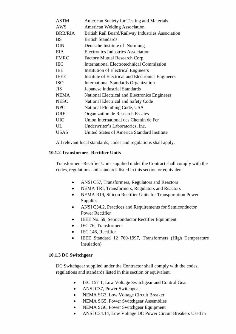
ASTM American Society for Testing and Materials
AWS American Welding Association
BRB/RIA British Rail Board/Railway Industries Association
BS British Standards
DIN Deutsche Institute of Normung
EIA Electronics Industries Association
FMRC Factory Mutual Research Corp.
IEC International Electrotechnical Commission
IEE Institution of Electrical Engineers
IEEE Institute of Electrical and Electronics Engineers
ISO International Standards Organization
JIS Japanese Industrial Standards
NEMA National Electrical and Electronics Engineers
NESC National Electrical and Safety Code
NPC National Plumbing Code, USA
ORE Organization de Research Essaies
UIC Union International des Chemin de Fer
UL Underwriter’s Laboratories, Inc.
USAS United States of America Standard Institute
All relevant local standards, codes and regulations shall apply.
10.1.2 Transformer- Rectifier Units
Transformer –Rectifier Units supplied under the Contract shall comply with the
codes, regulations and standards listed in this section or equivalent.
ANSI C57, Transformers, Regulators and Reactors
NEMA TRI, Transformers, Regulators and Reactors
NEMA R19, Silicon Rectifier Units for Transportation Power
Supplies
ANSI C34.2, Practices and Requirements for Semiconductor
Power Rectifier
IEEE No. 59, Semiconductor Rectifier Equipment
IEC 76, Transformers
IEC 146, Rectifier
IEEE Standard 12 760-1997, Transformers (High Temperature
Insulation)
10.1.3 DC Switchgear
DC Switchgear supplied under the Contractor shall comply with the codes,
regulations and standards listed in this section or equivalent.
IEC 157-1, Low Voltage Switchgear and Control Gear
ANSI C37, Power Switchgear
NEMA SG3, Low Voltage Circuit Breaker
NEMA SG5, Power Switchgear Assemblies
NEMA SG6, Power Switchgear Equipment
ANSI C34.14, Low Voltage DC Power Circuit Breakers Used in

Enclosures
EN 50 163
EN 50 123
EN 50 023
IEC 850, Level of Voltages for Railway and Subway Systems
10.2 Data Sheet
The Contractor shall provide – at the Proposal stage – all the performance and data
sheets for the additional Power Supply Equipment. On these sheets, the nominal
current, nominal voltage, size, weight, maximal performance and minimal
performance shall be indicated.
10.3 Power Simulation Study Inclusive of Load Flow Analysis
Immediately subsequent to Contract Award, the Contractor shall appoint a
specialist to conduct a computer simulated power study to validate his detailed
design.
The appointee shall demonstrate his experience and be subject to approval by the
Owner/Engineer.
11. POWER SYSTEM EQUIPMENT REQUIREMENTS
11.1 Rectifier Transformer Units
Substation rectifier transformer units shall be complete with all standards and specified
accessories, auxiliaries, controls and all necessary hardware, interconnecting buses,
wiring and devices.
Transformers shall be of the silicone oil filled type copper winding, high efficiency and
self air-cooled and suitable for outdoor installation, and meet the IEC 146 heavy traction
rating Class 6.
Silicone diode rectifier shall be indoor rated for 12 pulse output, 3000 KW, natural
convection air-cooled, free-standing, and metal enclosed. Air filters, if required, shall be
easily replaceable.
Each rectifier shall be complete with internal buses, connections and flanges for external
bases, protective devices, control wiring, terminal blocks and other necessary
accessories.
11.2 Overhead Catenary System
11.2.1 General
This specification defines the minimum requirements to be met by the
Contractor’s proposed Overhead Catenary System for the additional tracks
(Track 9, 11-15) of the expanded depot stabling area. The new tension length for
the new double cross-over turnout at North Avenue Station as well as the track
works included therein shall form part of the contract.
The catenary system supplied under this Contract shall be of a proven design

satisfying the system performance requirements defined in this document. The
catenary system shall be compatible with the existing OCS of MRT 3 and shall
also satisfy requirements regarding vehicle envelope, pantographs, service life,
safety reliability and maintainability.
11.2.2 Catenary Conductors
Contact wire shall be made up of 170mm2 solid grooved hard drawn copper
conforming to ASTM B47. The upper lobe of the contact wire shall match the
existing contact wire installed at MRT 3 to assure interchangeability of clips.
Other contact wire particulars include:
Weight : 1.511 kg/m
Breaking Load : 5900 kg
Coefficient of Expansion : 1.7 x 10⁻⁵ /0C
Resistance @ 200C : 0.1040 Ω/km
Modulus of Elasticity : 12000 kg/mm2
Conductor tensions shall be in accordance with the requirements of appropriate
ASTM standards. Thirty percent cross-sectional area loss due to wear of the
contact wire and the effect of the temperature change shall be taken into
consideration in the design of the conductor tension and ampacity.
The ampacity of the OCS shall meet the operational requirements of a four-car
train running at 120-second headways with a traction power configuration
proposed in the Concept Design Drawings.
11.2.3 Insulator
Insulators shall be porcelain, toughened glass polyester or other material with
proven rail or railway system service. Insulators shall have a single or multiple
sheds designed for minimum maintenance requirements and be self cleaning by
the action of rain. Double insulation is not required as it is not intended to carry
out “live line” work.
11.2.4 Splices
Each wire run of contact wire must be continuous from anchor to anchor except
in the case of cut-in insulators. Contact wire splices shall not be permitted. Feeder
wires may have splices as required to connect drum lengths of conductor. The
manufacturer shall warrant that splices are capable of withstanding tensions up to
100% of the breaking load of the conductor.
11.2.5. Section Insulators
The OCS Contractor is to provide Section Insulators at locations indicated. The
Section Insulators (SI) shall be designed and installed in such a way that it shall
provide a smooth passage to pantographs without any loss of contact and without
the introduction of unreasonable mechanical forces.
The SI shall permit the pantograph on the vehicle to collect the maximum demand
current without interruption during passage across the SI.

11.2.6 Feeder Conductors
Positive feeder conductors shall be insulated, non shielded, single conductors
suitable for use in wet and dry locations and rated 2,000 V DC, 90 0C conductor
temperature for normal operation, 120 0C for emergency operation, 250 0C for
short circuit conditions. The conductors shall be copper, conforming to ASTM
B189 material with Class C stranding and conforming to ASTM B8, wire EPR
or XLPE insulation and low smoke jacket.
The negative feeder shall be the same as the positive feeder cables except the
voltage rating shall be 600 V instead of 2000 V.
11.3. Negative Return
The negative feeder cables shall be the same as the positive feeder cables except the
voltage rating shall be 600 V instead of 2000 V.
Increasing the number of cross bonds along the line shall strengthen the Negative Return
to the Sub stations. Cross bonding between the 4 running rails shall be made every 250m.
In addition the bonds at rail expansion joints shall be increase by a further cable of 250
sqmm on each rail.
Similarly where Insulated Rail Joints are employed for signalling purposes, then the
current bonding shall also be upgraded.
Bonding at the main line turnouts shall be upgrade as practicable to ensure a low
resistance path for the return current.
12. SUPERVISORY, CONTROL AND DATA ACQUISITION (SCADA)
12.1 Introduction
The primary objectives of the SCADA Monitoring system for all the substations shall be
as follows:
12.1.1 Monitor and control of Electrical Distribution and Traction Power systems
within each Station Substation including the Depot.
12.1.2 Metering System to monitor and record power consumption separately for the
Traction sub-network, and the Lighting and Auxiliary Power Sub-network at each
Station Substation including the Depot.
12.1.3 Monitor condition of the Fire Alarm Systems located within certain nominated
station rooms including the Depot, i.e., Electrical, Signaling and
Telecommunications.
12.1.4 Monitor the conditions of the UPS equipment installed in all the Substations.
12.1.5 Monitor the condition of Escalators and elevators in designated stations.
12.2 Scope of Work
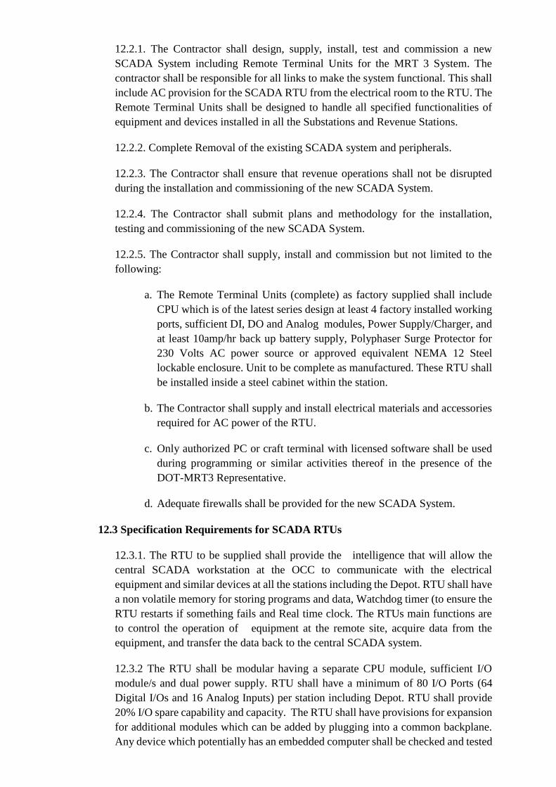
12.2.1. The Contractor shall design, supply, install, test and commission a new
SCADA System including Remote Terminal Units for the MRT 3 System. The
contractor shall be responsible for all links to make the system functional. This shall
include AC provision for the SCADA RTU from the electrical room to the RTU. The
Remote Terminal Units shall be designed to handle all specified functionalities of
equipment and devices installed in all the Substations and Revenue Stations.
12.2.2. Complete Removal of the existing SCADA system and peripherals.
12.2.3. The Contractor shall ensure that revenue operations shall not be disrupted
during the installation and commissioning of the new SCADA System.
12.2.4. The Contractor shall submit plans and methodology for the installation,
testing and commissioning of the new SCADA System.
12.2.5. The Contractor shall supply, install and commission but not limited to the
following:
a. The Remote Terminal Units (complete) as factory supplied shall include
CPU which is of the latest series design at least 4 factory installed working
ports, sufficient DI, DO and Analog modules, Power Supply/Charger, and
at least 10amp/hr back up battery supply, Polyphaser Surge Protector for
230 Volts AC power source or approved equivalent NEMA 12 Steel
lockable enclosure. Unit to be complete as manufactured. These RTU shall
be installed inside a steel cabinet within the station.
b. The Contractor shall supply and install electrical materials and accessories
required for AC power of the RTU.
c. Only authorized PC or craft terminal with licensed software shall be used
during programming or similar activities thereof in the presence of the
DOT-MRT3 Representative.
d. Adequate firewalls shall be provided for the new SCADA System.
12.3 Specification Requirements for SCADA RTUs
12.3.1. The RTU to be supplied shall provide the intelligence that will allow the
central SCADA workstation at the OCC to communicate with the electrical
equipment and similar devices at all the stations including the Depot. RTU shall have
a non volatile memory for storing programs and data, Watchdog timer (to ensure the
RTU restarts if something fails and Real time clock. The RTUs main functions are
to control the operation of equipment at the remote site, acquire data from the
equipment, and transfer the data back to the central SCADA system.
12.3.2 The RTU shall be modular having a separate CPU module, sufficient I/O
module/s and dual power supply. RTU shall have a minimum of 80 I/O Ports (64
Digital I/Os and 16 Analog Inputs) per station including Depot. RTU shall provide
20% I/O spare capability and capacity. The RTU shall have provisions for expansion
for additional modules which can be added by plugging into a common backplane.
Any device which potentially has an embedded computer shall be checked and tested

by the contractor or the supplier to verify compliance. Contractor shall ensure
compatibility checks of software configuration versus actual hardware installed.
12.3.3. Programmability and configurability shall conform to IEC1131-3 standards.
RTU shall provide clear indication of local and remote Diagnostics. RTUs have the
ability to initiate reporting to the SCADA master. Functionalities such as time
stamping, memory capacity to store data in the event of loss of communications,
ability to do calculations shall b supported.
12.3.4. RTU shall provide peer to peer communications or RTU to RTU
communication including store and forward capability. RTU Shall support data rates
from 1200 baud FSK, 9600 baud data up to 64 kbps and shall have serial ports to
interface with PLC's.
12.3.5. The SCADA System shall be powered with an electrical supply 230 V AC,
60 Hz. It shall be tolerant to voltage variations of 10% of the nominal; -15% (for
500ms duration) of the nominal voltage and frequency variations of 2%, without
any reduction in the efficiency of the system. An Uninterruptible Power Supply
(UPS) system with special provision for smoothing and reduction of the impulse
voltages, necessary for the protection of the equipment from the failures of the main
power supply of the Network and main disturbances shall supply power to the
SCADA equipment.
12.4 Interface with Equipment Provided by Other Sections
The Contractor shall be responsible for the interfaces between the installed
equipment and additional ones and equipment provided by other sections of the
Works.
12.5 RTU at the Stations
The RTU at the peripheral station shall be located at the traction substation or in
the Line station. The incoming and outgoing circuits shall be connected with the
appropriate terminals within the cubicles. The Contractor shall declare, for DOT-
MRT3-MRT3 Engineer’s approval, the degree of protection of these cubicles. The
contractor shall be responsible for all incoming and outgoing circuits. The incoming
and outgoing circuits shall not have any direct electrical connection with the
remote-control equipment logic. The Contractor shall, for the DOT-MRT3
Engineer’s approval, declare the degree of isolation to be proposed.
12.6 Environmental Specifications/ and Standards
The SCADA RTU shall be able to perform all applicable operations reliably under
a temperature range of -5o C to 50o C and relative humidity 60% to 95%. It must
meet or exceed EIA standards BS – 204 B and BS – 152 B. It shall conform to
Ingress Protection standards against dust, vibration, insects and rodents.
The RTU shall meet or exceed the SWC standards as defined in IEEE C37.90A for
al inputs and outputs. The enclosure shall conform to UL611 standards.
The RTU shall conform to the provisions of EN 61000 standards.

13. DEPOT/STABLING
13.1. TRACKWORKS
Railways are generally recognized as a safe, efficient and economical mode of
transport all over the world and are increasingly experiencing capacity constraints.
At present, MRT3 has already approached the limit of practical capacity. Therefore,
capacity expansion and improvements become a particularly timely and important
objective to be implemented. This will primarily address passenger congestion
during peak hours as well as future ridership demands.
The construction and installation of additional ballasted stabling tracks at the Depot
shall not disrupt the current system operation and shall be designed in accordance to
existing system specifications and standards to assure compatibility.
The construction and installation of additional ballasted stabling tracks at the Depot
must completed within One Hundred Eighty Calendar Days from the Start date.
13.1.1. GENERAL
The provisions stated in this document are related to the specific requirements
applicable to the track system for the construction of additional ballasted
stabling tracks at MRT 3 Depot.
Trackworks system under this Contract shall conform to the most recent
practices of the American Railway Engineering Association (AREA), Union
Internationale des Chemins de Fer (UIC), International Standards
Organizations (ISO) and the practices and specifications of recently
constructed mass transit systems of equivalent capacity and characteristics
constructed within the last five (5) years. It shall be of proven design
satisfying the system performance requirements and it shall be compatible
with the existing MRT3 system. It shall also satisfy requirements with
regards to train kinematic gauge, service life, reliability, maintainability and
safety.
The works shall include design; supply; installation; testing and
commissioning; obtaining all permits from government authorities; and
everything, whether permanent or temporary in nature, necessary for the safe
and proper execution of work and for the fulfillment of all obligations
required under this contract. It shall also include the training of the Employer
maintenance personnel; the supply of maintenance manuals, repair manuals
and as-built records; and the rectification of defects liability period of the
installed ballasted tracks system.
13.1.1.1. Scope of Work This section specifies the scope of work of the Contractor as follows:
a. Design, supply and construction of six (6) additional stabling ballasted
tracks at the MRT3 Depot with complete support and fastening accessories.
b. Design, supply and installation of fourteen (14) sets of turnout at MRT3
Depot with complete accessories such as but not limited to timber/switch
ties, fasteners, switch/guard rails and manual switches.

c. The workmanship shall be in accordance with specifications and quality
standards and shall cause no disruption to MRT3 Depot operations.
d. Provide additional 30 meters track extension on both ends of Track 23.
13.1.1.2. Standards and Regulations
The work shall conform to the laws and regulations existing in the Philippines and
shall generally be in compliance with the Philippines’ Standards and Codes of
Practices, unless specifically provided for in this document.
In addition, the following standards may be considered as long as they do not
compromise the Employer’s Requirements
ACI - American Concrete Institute
ANSI - American National Standards Institute
ASA - American Standard Association
AREA - American Railway Engineering Association
CEN - Comité Européen de Normalisation
ISO - International Standard Organization
UIC - Union Internationale des Chemins de Fer
JIS - Japanese Industrial Standards
AS - Australian Standards
BS - British Standards
AASHTO - American Association of State Highway &
Transportation Office
ASTM - American Society for Testing and Materials
PCI - Prestressed Concrete Institute
13.1.1.3. Special Site Conditions
The Contractor acknowledges that it has thoroughly investigated and satisfied
itself as to all general and local conditions affecting the work. The failure of the
Contractor to accustom himself with such conditions will not relieve him from any
responsibility for completing the works under this contract. The Contractor shall
be fully responsible for any damage caused to the site or other existing facilities
due to his track works equipment movements and transportation and restore these
damages to its original state at his own expense.
13.1.1.4. Design Criteria The following data will constitute for the design of tracks for MRT3:
a. Track gauge - 1435mm
b. Train speed - 15kph
c. Concrete tie spacing - 750mm
d. Rail inclination - 1:20
e. Axle Load - 90kn
f. Ballasts depth minimum - 150mm
g. Rail profile - UIC 54h. Depot track minimum radius - 25m i. Concrete tie length - 2500mm
j. Concrete tie weight - 250kg
k. Concrete tie compressive
strength
l. Concrete tie stress transfer
- 50Mpa
- 30Mpa

strength
m. Pre-stressing wire diameter - 6.5mm
n. Pre-stressing wire ultimate - 1700MPa
tensile strength minimum
13.1.2. MATERIALS REQUIREMENTS
Track works materials needed for the construction of additional ballasted tracks shall
be complete with all accessories; shall have passed all the required testing in
accordance to specifications and standards; and, shall be approved by the Engineer
before incorporating to work. The Contractor shall ensure materials availability for
small quantity production intended for maintenance use.
13.1.2.1. Earthworks
All materials to be incorporated to work should pass all required testing and
certification and should be in accordance with the requirements of Part C
Earthwork DPWH Standard Specifications.
13.1.2.2. Aggregate Base / Sub-ballast The aggregate base (sub-ballast) shall be from approved source and conform to
the requirements of Item 201 Aggregate Base Course of the DPWH Standard
Specifications.
13.1.2.3. Ballast Ballasts shall be of crushed rock containing no carbonates or slag. They shall be
hard, strong, angular, and made of durable particles. Ballast rocks shall be highly
resistant against crushing, grinding, and must be chemically inert. They shall be
weather resistant and of homogenous structure. The ballast shall be free from
dust, soil, clay, plant matter and substances likely to be detrimental to the rocks.
13.1.2.4. Special Trackworks
The supply of the special trackworks shall be complete to include a fastening
system.
13.1.2.4.1 Technical Requirement
a. Special trackwork shall be designed either 1 in 3 straight (10.8 m long)
or 1 in 2.4 curve (10m long) lateral turnouts with a minimum radius of
25m. It shall generally follow the UIC practice.
b. Switches & crossings baseplates fastening shall be designed for
Pandrol type e-series elastic rail clip.
c. All switches shall have an undercut stock rail, and switch rails utilizing
UIC 54 grade 900A rail section with forged transition between tongue
rail and standard rail. Switch rails shall be supported on raised slide
plates incorporating a resilient bracing system for fastening of the
stock rail.
d. Minimum clearance between open switch and stock rail shall be 45mm
and switch blade opening on the toe is 110mm. Flangeway clearances
through crossing and check/guard rail shall be 30mm and 26mm

respectively.
e. Minimum point protection dimension is 1404 mm.
13.1.2.4.2 Switches
Switch and stock rails shall be made from UIC 54. It shall be face machined in
order to obtain the required design profile and shall be fitted together. Slides
base plates shall include resilient bracing system fastened to the stock rail. The
hand lever and connecting rods for the switch operation shall be included in
the switch supply.
13.1.2.4.3 Crossings
Turnout crossing shall be made from chrome vanadium built up crossing steel
grade 900A. The crossing shall offer great resistance to impact especially at
the nose component and shall be allowable for welding operations under
normal site conditions.
13.1.2.4.4 Guard and Check Rails Guard and check rails shall be machined from UIC 33 (U69) rail profile of not
harder than grade 900A and supported by a fabricated support base plate with
a flange way clearance of 26mm. Bolt connection shall utilize steel
components conforming to UIC leaflets 864/2.0 and 864/3.0
13.1.2.4.5 Special Trackwork Plates and Fastening System
All track work plates shall be flat and have no cant. Plates shall hold the rail
laterally, vertically and longitudinally and shall be capable of supporting and
transferring the load from the rail to the switch ties.
All plates for guard/check rail, switches and crossings shall be at least 20mm
thick and 200mm wide. The length shall be designed so that minimum
number of plates of different length will be required. Bolt connection shall
utilize steel components conforming to UIC leaflets 864/2.0 and 864/3.0
Special tracks fastening system shall conform to 3.1.2.10.3 Fastening System.
13.1.2.4.6 Switch and Crossing Ties
Switch and crossing ties shall conform to 3.1.2.6 Timber Cross and Switch
Ties.
13.1.2.4.7 Joints All special trackworks joints in the Depot unless specified herein shall be
alumino-thermic welded by an approved welding materials and procedures for
UIC 54 rail and shall conform to specifications required by Welding of Rails.
13.1.2.4.8 Coach Screw
Coach Screw spikes which will be used to fasten the plates down to the
wooden switch ties shall conform to UIC leaflet 864/1.0 appertaining to the
technical specifications for the supply of coach screws
13.1.2.5. Monoblock Concrete Ties

On stabling tracks, concrete ties shall be monoblock pre-tensioned concrete. It
shall be 250kgs and 2500mm long. Alternative concrete ties could be considered
if they are compatible with the existing concrete ties in MRT3 in terms of general
profile, dimension and strength. The Contractor must ensure that alternative
designs must have a successful history performance of at least five (5) years in
service under comparable conditions. Any alternative design must be specifically
approved by the Engineer.
13.1.2.5.1. Concrete
The concrete minimum 28 days design compressive strength for concrete ties
shall be 50 Mpa as determined by ASTM C39.
13.1.2.5.2. Aggregates
Both fine and course aggregates shall meet the requirements of the AREA
specification for aggregates.
All aggregates shall pass all required testing and shall conform to Item 703 of
DPWH Standard Specifications.
13.1.2.5.3. Admixtures Chemical admixtures for concrete shall conform to ASTM C494. Additives
containing chlorides shall not be used.
Suitable admixtures may be used to modify certain properties of concrete.
However, as they may at the same time adversely affect other important
concrete quality, the Contractor shall carry out testing on concrete to which
they are added.
13.1.2.5.4. Pre-stressing Tendons
The wire shall be 6.5mm diameter complying with ASTM A864 or ASTM
881, and with a minimum tensile strength of 1700 MPa. Tendons shall not be
contaminated with mud, oil, grease or chloride salts. Tendons with corrosion
shall not be used.
13.1.2.5.5. Rail Fastening System
Concrete ties associated rail fastening system shall be Pandrol type e-series
elastic rail clip manufactured by Pandrol Australia Pty. Ltd in accordance with
UIC specifications.
13.1.2.6. Timber Cross and Switch Ties
The ties shall be unbored and air dried hardwood of untreated Jarrah or Karri
timber species for non-exposed Depot turnouts or any approved equivalent.
13.1.2.7. Rails
Standard rail cross-section shall be UIC 54 of grade 900A with a minimum tensile
strength of 880 Mpa and shall meet the requirements of the UIC Standards.
13.1.2.8. Thermit Welding

This refers to the materials and other services required for joining UIC 54 using
alumino-thermic welding process.
13.1.2.8.1. Thermit Welding Kits
Thermit welding materials shall be manufactured by Thermit
Australia Pty Ltd or approved equivalent compatible to the
existing welding materials used in MRT3.
13.1.2.8.2. Thermit Welding Equipment
Welding equipment and accessories required for welding
operation shall be use and installed in accordance to
manufacturer’s recommendation, contract drawings and applicable
specifications.
13.1.2.9. Grade/Road Crossings
All materials needed for this work shall meet the requirements specified in the
reference standards and specifications.
13.1.2.9.1 Grade/Road Crossings Bituminous Materials (Asphalt)
Materials shall conform to the requirements of Item 307 of the DPWH
Standard Specifications.
13.1.2.10. Other Track Materials Other track materials and appurtenances needed to complete the work shall be
approved materials by the Engineer and installed in accordance to manufacturer’s
recommendation, contract drawings and applicable specifications.
13.1.2.10.1. Insulated Rail Joints
Rail joints shall be made up of two rolled steel fishplates designed to fit UIC
54 rail profile and with four holes drilled by an approved drilling machine.
Bolts shall be of high strength provided with spring and flat washers and shall
conform to applicable UIC standards.
13.1.2.10.2. Check Rails
Check rail shall be machined from UIC 33 profile of not harder than grade
900A rail steel and supported by brackets connected to the rail. Bolt
connection shall utilize steel components conforming to UIC leaflets 864/2.0
and 864/3.0 appertaining to technical specifications for the supply of track
bolts and spring washers respectively.
Check rail shall be provided for a curve ballasted track in the Depot if the
radius in equal to or less than 50 meters. Checkrail brackets shall be of
approved materials conforming to UIC standards.
13.1.2.10.3. Fastening system The rail fastening system for MRT3 shall be Pandrol type e-series elastic rail
clip made by Pandrol Australia Pty. Ltd.
13.1.2.10.4. Lubricants

The Contractor shall provide a dry film lubricant for application to special
tracks sliding plates. It shall have a low electrical conducting properties and
subject for Engineer’s approval.
13.1.3. CONSTRUCTION REQUIREMENTS
The Contractor shall be responsible for the construction means, methods, techniques,
sequences and procedures for coordinating all portions of the Work under the
Contract Documents.
The Contractor shall provide all superintendence during the execution of the Work as
may be necessary for the proper fulfillment of the Contractor’s obligations under the
Contract. It shall include the supervision and inspection by qualified professional
personnel experienced in railway construction whose responsibility shall be to ensure
the technical standards and workmanship, materials, and quality are being maintained
in accordance with the Scope of Work.
The Contractor shall design, supply and install a ballasted tracks or special tracks
system which satisfies to the minimum requirements of the specification and
Employer’s Requirements. The Contractor shall submit full details of the proposed
design to the Engineer for review and approval and shall not commence until written
acceptance has been received from the Engineer.
13.1.3.1 Ballasted Trackworks Construction This section applies to construction of all ballasted tracks both plain and special
tracks for MRT3 Depot.
13.1.3.1.1 Quality Assurance Program
a. The Contractor shall establish, implement and maintain a quality
assurance program to provide verification of compliance with contract
requirements. The quality assurance program shall consist of detailed
procedures and instructions for monitoring and controlling those
activities related to quality during design, fabrication, delivery,
handling, storage, installation, inspection and testing. The areas which
the quality assurance program shall address include the following:
i. Review and control of quality procedures and instructions,
ii. Calibration of construction measuring and testing tools and
equipment,
iii. Qualification and certification of Personnel,
iv. Tests and inspections
v. Procurement quality assurance,
vi. Identification and control of items, and
vii. Handling, delivery and storage of materials.
b. Adequate records shall be maintained by the Contractor in accordance
with the requirements of his quality assurance program and shall
include the following:
i. Evaluation of subcontractors’ and suppliers’ qualifications and
past performance,
ii. Results of inspections and tests,
iii. Certificates of compliance,
iv. Qualified procedures for special processes,
v. Personnel certifications,

vi. Measuring and test equipment calibration certificates, and
vii. Transmittals of contract related information.
c. The appropriate requirements of the Contractor’s quality assurance
program shall be imposed upon subcontractors and suppliers.
d. The quality assurance activities of the Contractors/subcontractors and
suppliers will be subject to Engineer’s verification, inspection and
audit at any time.
13.1.3.1.2 Submittals
The Contractor shall submit the following:
a. The Quality Assurance Program
b. Applicable reference codes
c. Detailed construction schedule
d. Detailed design and shop drawings for all Contractors supplied
materials and other track materials required including fastening system
for the construction of both ballasted track and special track works.
e. Pre-construction inspection reports
f. Qualifications of registered Surveyors
g. Certificate of calibration for specified tools and equipment by independent testing laboratory accepted by the Engineer
h. Details and arrangement of equipment, materials and personnel to be
used during the various construction stages. Maximum construction
loads shall be identified and submitted to the Engineer for review prior
to any construction equipment being allowed to construction site
i. Details for the protection of rails, special track works, other track
materials and facilities from damage by construction equipment and
road traffic,
j. Production information forms and test reports on welds,
k. Rail laying records,
l. Calculation to determine Neutral Rail Temperature for Depot.
m. Method statement for natural or artificial de-stressing works for both
ballasted track and special track works in Depot.
n. Procedures for handling and anchoring CWR,
o. Procedures for rail grinding and subsequent cleanup including a daily
rail grinding log indicating grinding date, locations, number of passes
of grinder, manufacturer and model number of grinder,
p. And all other documents needed for the completion of the work and
subject for Engineer’s review and approval.
13.1.3.1.3 Electrical Testings
The Contractor shall perform all tests of electrical resistance and continuity for
insulated rail joints, running rail, running rail to running rail and track to earth.
Any installations which fail shall be rectified by the Contractor at his own
expense and retested until acceptance by the Engineer.
13.1.3.1.4 Inspection
The Contractor shall inspect the construction area prior to installation of
trackworks for any damages and discrepancies with propose installation plan
and correct said discrepancies authorized by the Engineer.
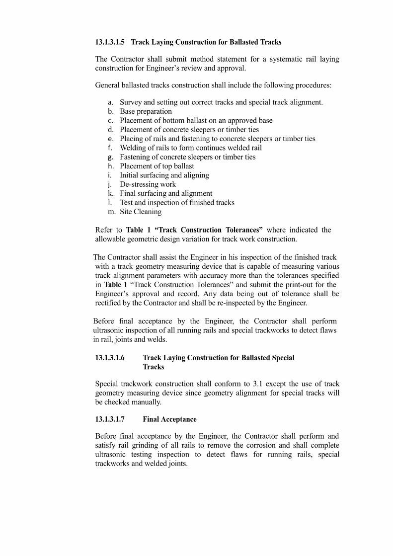
13.1.3.1.5 Track Laying Construction for Ballasted Tracks
The Contractor shall submit method statement for a systematic rail laying
construction for Engineer’s review and approval.
General ballasted tracks construction shall include the following procedures:
a. Survey and setting out correct tracks and special track alignment.
b. Base preparation
c. Placement of bottom ballast on an approved base
d. Placement of concrete sleepers or timber ties
e. Placing of rails and fastening to concrete sleepers or timber ties f. Welding of rails to form continues welded rail g. Fastening of concrete sleepers or timber ties h. Placement of top ballast i. Initial surfacing and aligning j. De-stressing work k. Final surfacing and alignment
l. Test and inspection of finished tracks
m. Site Cleaning
Refer to Table 1 “Track Construction Tolerances” where indicated the
allowable geometric design variation for track work construction.
The Contractor shall assist the Engineer in his inspection of the finished track
with a track geometry measuring device that is capable of measuring various
track alignment parameters with accuracy more than the tolerances specified
in Table 1 “Track Construction Tolerances” and submit the print-out for the
Engineer’s approval and record. Any data being out of tolerance shall be
rectified by the Contractor and shall be re-inspected by the Engineer.
Before final acceptance by the Engineer, the Contractor shall perform
ultrasonic inspection of all running rails and special trackworks to detect flaws
in rail, joints and welds.
13.1.3.1.6 Track Laying Construction for Ballasted Special
Tracks
Special trackwork construction shall conform to 3.1 except the use of track
geometry measuring device since geometry alignment for special tracks will
be checked manually.
13.1.3.1.7 Final Acceptance
Before final acceptance by the Engineer, the Contractor shall perform and
satisfy rail grinding of all rails to remove the corrosion and shall complete
ultrasonic testing inspection to detect flaws for running rails, special
trackworks and welded joints.

13.1.3.2 Earthworks
The work specifies in this section consists of stripping topsoil, excavating and
backfilling to attain indicated sub-grades and grades and conforms to Part C
Earthwork of DPWH Standard Specifications latest edition.
13.1.3.2.1 Excavation
Remove materials within the indicated limits. The sub-grade is the lowest
elevation of excavation and it shall be inspected and approved by the Engineer
prior to placement of grade materials. Excavated materials satisfying the
requirements of Item 104 of the DPWH Standard Specifications may be used
as fill materials. Remove all surplus excavated materials.
13.1.3.2.2 General Excavation
a. Generally refers to excavation for the construction of trackway and
roadway as indicated on the design drawings
b. Sub-grade preparation at at-grade trackway and roadway in
excavation areas shall have a minimum bearing capacity of 150
KPa and shall conform to Item 105 of DPWH Standard
Specification
c. Fill unauthorized excavation with approved fill materials by the
Engineer and compact to at least 90 percent of maximum dry
density in accordance with ASTM 698.
13.1.3.2.3 Structure Excavation
Ensure that sub-grade, other than rock, is not disturbed. If the sub-grade
material is disturbed, either compact the disturbed material to not less than
90 percent of maximum dry density or remove and replace the disturbed
material with concrete of the same class as the structure.
Gradation ASTM D422
Liquid Limit ASTM D4318
Plasticity Index ASTM D4318
Resistance (R. Value) ASTM D2844
Maximum Density ASTM D1557
Sand Equivalent California test 217 or ASTM
D2419

The Contractor shall make sure that demolition and excavation of the
existing concrete road affected by the project shall not disrupt adjacent
traffic and without damage to other existing facilities.

13.1.3.2.4 Filling, Backfilling and Compacting
Refer to Item 104 of DPWH Standard Specifications.
13.1.3.2.5 Contractor’s Quality Control Prior to and during the execution of the work, the Contractor’s Testing
Laboratory shall perform all necessary soils tests in accordance with the
minimum testing requirements and Item 104 of DPWH Standard
Specifications.
13.1.3.2.6 Submittals
The Contractor shall submit the following for Engineer’s review and approval:
a. Equipment to be utilize in the work
b. All necessary methods and procedures
c. All testing results and other materials certification
13.1.3.3 Aggregate Base / Sub-ballast
This section specifies the furnishing, placing, spreading and compacting of
crushed aggregate base or sub-ballast in one or more layers in accordance with
specification and contract drawings.
13.1.3.3.1 Placing, Spreading and Compacting
The approved aggregate base course (sub-ballast) shall be placed, spread and
compacted in conformance with the requirement of DPWH Standard
Specifications Items 200.3.2 and 200.3.3 and contract drawings.
13.1.3.3.2 Submittals
The Contractor shall submit the following for Engineer’s review and approval:
a. Equipment for to be utilize in the work
b. All necessary methods and procedures
c. Materials grading and testing results
d. Materials source and certificate of compliance
13.1.3.4 Ballast

The Contractor shall supply and install ballasts of approved materials required for
the construction of additional ballasted tracks in MRT3 Depot.
13.1.3.4.1 Testing Requirements

a. Grading
b. Deleterious substances present in prepared ballasts shall not exceed the
following:
c. Percentage of wear shall not exceed 25% after testing in a Los Angeles
abrasion testing machine in accordance with ASTM C535. d. The bulk specific gravity and percentage of absorption shall be 2.60
and 1% respectively in accordance with ASTM C127.
Size of Sieve Opening % Passing by
Weight
Ballast for MRT 3 (Size 3 AREA
Manual)
63.5 mm 100%
50.8 mm 95-100%
38.1 mm 35-70%
25.4 mm 0-15%
12.7 mm 0-5%
Material Percent by
Weight Method of Test
Soft Pieces 5% AASHTO -
T189
Fine less than No. 200 Sieve 1% ASTM C117
Clay lumps and Friable
Particles 0.5% ASTM C142
Flakiness Index 20% BS 812

e. The magnesium carbonate content shall be tested and defined in
accordance with ASTM C25. No carbonates shall be allowed.
13.1.3.4.2 Submittals
The Contractor shall submit the following for Engineer’s review and approval:
a. Ballast source certificate of compliance
b. Tests results mentioned in 3.1.3.4.1 Testing Requirements
c. And all other test required to complete the work.
13.1.3.5 Special Trackworks
The Contractor shall design, manufacture, supply, deliver and install complete sets
of special trackworks including general arrangement of ties and all associated
fastening system in conformance to applicable specifications and compatible to
the existing special track system of MRT3.
13.1.3.5.1 Quality Assurance
Shall conform to 3.1.3.1.1 Quality Assurance Program
13.1.3.5.2 Submittals The Contractor must submit the following for Engineer’s review and approval:
a. Shop drawings showing details and arrangements of each special track
work component and the variants to each components,
b. Product data consisting of a listing of product types, name of supplier,
model number product literature, materials composition and method of
manufacturing.
c. Proposed welding and test procedures for special track work,
d. Contractor’s system specification for marking and identifying sizes,
types and composition of products, as well as identifying parts for the
purpose of proper location during installation,
e. The proposed steel baseplate design including elastic spring clips, and
mounting bolts or screw spikes, as applicable for each different plate,
f. Certificates of material compliance required by the specifications,
g. Test report of chemical analysis and Brinell hardness of running rail,
electric insulation, and other tests required by this specification,
h. All tests and analysis required on the running rails by the UIC
Specifications shall be performed at the mill or by the Contractor and
the test results shall be submitted to the Engineer,
i. A description of shipping, handling, unloading and stacking
procedures.
13.1.3.5.3 Inspection and Acceptance
Prior to shipment, at least one (1) turnout shall be completely assembled in the
manufacturer’s fabrication shop for inspection by the Engineer.

Variations from the approved Shop Drawings and these Specifications will
constitute non-compliance and will not be approved for shipment until proper
modifications are made and accepted by the Engineer.
For the inspection of material under this Contract, the terms set forth in
“Materials Inspection, Test and Claims,” under the UIC Specifications for
Special Track Work shall apply, except as listed herein.
The Contractor will make available to the Engineer all the necessary facilities
to examine the work during its progress as well as the finished product to
satisfy him that the materials comply with the Specification. The Contractor
will provide templates and 1meter straight edges to check flange ways, rail
end, and switch rail planning.
The Contractor shall give the Engineer advance written notice for inspection at
least ten working days.
13.1.3.6 Monoblock Concrete Ties
This section specifies requirement for the design, production, delivery and
installation of pre-stressed monoblock concrete ties with complete rail fastening
system compatible with the existing system of MRT 3.
13.1.3.6.1 Design Criteria
As specified in 2.1.3.1.4 Inspection
13.1.3.6.2 Marking, Delivery, Storage and Stacking
Mark on top of the ties with indented or raised letters to indicate the
manufacturer, year of manufacture, mould number and project identification.
Contractor must securely brace ties during transportation to prevent from any
movement that could cause damage. During transportation, ties should be in
horizontal position supported with wooden spacer blocks so that the top
surface does not make contact with ties loaded above. Do not stack ties more
than 6 layers during transport.
The Contractor shall store concrete ties in a location that would avoid
additional handling until the final distribution or within the area designated by
the Engineer.
13.1.3.6.3 Quality Assurance and Inspection Before production commences, the Contractor shall prepare a quality control
manual for approval by the Engineer and shall include details of:
Management organization
Responsibilities of production and quality control personnel
Plant standards
Checks to be carried out by the production personnel
Inspection and testing to carried out by quality control personnel
Procedures for approving sources of materials

Procedures to ensure all measuring equipment is properly calibrated
Procedures to ensure that concrete ties are not shipped until acceptance
load testing is complete
Quality audit procedures
This section shall also conform to 2.1.3.1.1 Quality Assurance Program
13.1.3.6.4 Submittals
a. Quality control program
b. Concrete mix design
c. Concrete curing procedures
d. Method and procedures for concrete ties production
e. Tensile strength test results
f. Rail fastening system technical specifications and drawings
g. Pre-stressing wire technical specification
h. All materials test results needed to complete the work and before
incorporating to concrete ties production
This section shall also conform to 2.1.3.1.2 Submittals
13.1.3.7 Timber Cross and Switch Ties
This section comprises specifications for the supply and installation of new timber
cross ties, switch ties, switch machine ties intended for Depot turnout construction
and shall be from approved source and shall be compatible with the existing
materials.
13.1.3.7.1 Quality Requirements
Ties shall be free of defects that may impair their strength or durability.
Defects such as decay, large splits, large shakes, excessive grain slope, large
holes and large knots will not be acceptable. All timber ties shall be cut by saw
and the cross section shall be 225mm wide and 140mm deep. Standard cross-
ties shall have a length of 2440 mm. Size and length tolerances shall be as
follows:
a. Width - plus 10 mm/minus 0
b. Depth - plus 12 mm/minus 0
c. Length - plus 50 mm/minus 0
Each timber shall be examined on the top, bottom, sides and ends. Cross and
switch tie shall not exceed the following allowable amount of defects:
Type of Warp Allowable Amount
Spring 25 mm
Bow 9 mm
Crook 25 mm
Cup 6 mm
Twist 6mm

All ends of timber ties shall be cut square and provided by anti-split end
plates. End plates shall be applied flush to the end surfaces of the tie and will
remain securely seated and withstand rail vibration.
The Contractor is required to determine the number and dimensions of switch
ties for each turnout and shall be specified in general turnout arrangement
drawing and shall conform to dimension tolerances stated above.
13.1.3.7.2 Testing and Inspection
The Contractor shall assume full responsibility for all required testing and give
the Engineers sufficient notice when testing in any form is proposed so that
Engineers could inspect and witness the tests.
The Engineer may inspect the ties during production process or after delivery
at the job site and or after placement on the grade for track utilization.
Whether or not the Engineer test or inspect any materials, the Contractor will
not be relieved from any responsibility regarding defects or other failures to
meet the contract requirements.
13.1.3.7.3 Marking, finishing and Workmanship
Ties shall be branded or marked permanently with approved materials to show
ownership, manufacturer’s identification and year of production on one end.
Tie machining and workmanship shall follow and conform to the applicable
standards.
13.1.3.7.4 Submittals
The Contractor shall submit the following requirements:
a. Quality control program for all method and procedures to ensure
compliance with standards quality
b. The name of timber and its source for approval,
c. Timber ties Manufacturers specifications
d. Official certificates of inspection in conformance with the reference
standards including data regarding hammer band confirming timber
grading,
e. Data regarding proposed tie machining & stamping,
f. The Inspectors report form duly accomplished (as described by the
reference standards for Inspection of Timber Products) and submit to
the Engineer prior to tie shipment from the production plant,
g. Certification that the manufacturer has a minimum 5 years experience
in manufacturing timber switch ties and as a supplier to major rail
transit system.
h. Completed tests results.
13.1.3.8 Rails

This detailed specification applies to manufacture, inspection, testing, and supply
of new rails intended for the construction of additional stabling tracks at MRT 3
Depot.
13.1.3.8.1 Tests Requirements The Contractor shall perform the following tests:
a. Chemical composition analysis
b. Mechanical property
c. Tensile strength
d. Brinell hardness test
e. Shape, dimension and appearance inspection
f. Ultrasonic test
Each rail shall be ultrasonically tested over its full length to determine its
interior conditions prior to delivery to the work site. The rail must be free
from all detrimental defects having unfavorable effect on the strength of the
rail while in service.
The Contractor shall be responsible for all required testing and shall give
Engineer sufficient notice of proposed testing so that Engineer may inspect
and witness the tests in accordance to UIC specifications.
13.1.3.8.2 Quality Assurance and Inspection This section shall also conform to 3.1.3.1.1 Quality Assurance Program.
The quality system for rail manufacture shall be certified at least to ISO 9002
and shall be based on precise terms and conditions which ensure compliance
with the various rail specifications.
The Engineer will monitor from time to time the Contractor’s methods,
procedures, and processes for compliance with the accepted program and all
records of test and inspection.
13.1.3.8.3 Marking, Packaging, Handling, Transporting and Storage
a. Obligatory marks in the UIC 54 rail shall be in accordance with UIC
Code 860 O as follows in-relief marks which shall be very legible in
characters raised on one side of the web indicating:
i. Identification mark of the mill,
ii. Year of manufacture (last two figures),
iii. Symbol of steel grade, and
iv. Symbol of rail section in kg/m weight
b. The Contractor shall submit for approval a detailed procedure for
marking, packaging, delivery, handling, transporting and storage of
rails. Contractor shall take all necessary precautions to ensure that
rails will not be bent, deformed or damage during handling and

transporting and it shall be kept clear of any standing water during
stacking and storage.
13.1.3.8.4 Submittals
The contractor is required to submit the following:
a. Certification that rail manufacturer has at least 10 years experience in
the large scale manufacture of running rails as specified herein and as a
supplier of rail to major railroads and transit systems.
b. Certification from supplier or manufacturer that all the rails
manufactured and delivered on site are in conformance with UIC
specification and that the required tests were performed as represented
by the submitted test result.
c. Tests Certificates as prescribe in 2.1.3.8.4 Test Requirements
d. Detailed production process of rails
e. Certification of the manufacture’s process in accordance to ISO 9002.
f. And all other documents needed for the completion of work.
Rails shall be guaranteed by the supplier/manufacturer from date of manufacture
plus 5 years to the date of acceptance of works against any defects attributable to
manufacture.
13.1.3.9 Track Appurtenances and Other Track Materials
This section specifies the requirements for the design, supply, and installation of
other track materials needed for the construction of additional ballasted tracks and
shall be compatible with existing track materials of MRT3 Depot.
13.1.3.9.1 Submittals
The Contractor shall submit all detailed design drawings for each trackworks
materials in accordance with applicable specifications and subject for
Engineer’s review and approval.
a. Detailed design drawing for each Other Track Materials and
corresponding fastening system
b. Installation methods and procedures
c. Materials manufacturer specifications
d. Material compliance certificate and testing results
e. And other submittals required to complete the work
13.1.3.10 Welding of Rail
This section specifies the furnishing of all labor, material, equipment and services
by the Contractor which are necessary for joining new UIC 54 rails using
alumino-thermic welding process.
13.1.3.10.1 Rail Welding
Welding process shall include the following procedures:

a. Inspection of rail ends
b. Rail cutting and set the required gap
c. Loosening of rail fastenings
d. Rail end preparation and alignment
e. Preheating and welding
f. Finishing and alignment
g. Weld testing
h. Replacement of defective welds
i. Records of thermit welding
Each procedure shall be in accordance with the AREA Manual for Railway
Engineering, the products or welding kit specifications itself and other
applicable standards.
13.1.3.10.2 Quality Assurance
This section shall conform to requirement in 2.1.3.1.1 Quality Assurance
Program.
13.1.3.10.3 Weld Testing
All weld testing and submittals shall be performed by a duly accredited
independent testing laboratory in accordance with quality control requirements
and applicable standards. In order to qualify the welding kits, welding crews,
and production welds; the following test shall be carried out:
a. Radiographic testing
b. Ultrasonic testing
c. Slow bend testing
d. Hardness test
e. Rolling load test
f. Magnetic particle test
g. Visual test
13.1.3.10.4 Tolerances
All alumino-thermic welds will be in the suspended portion of rail between
supports. The weld shall not encroach 150mm from tie ends or baseplate
support. Finished weld using 1 meter straight edge shall have the following
tolerances:
a. Rail head surface +0.3 / 0.0 mm
b. Rail gauge face +0.3 / 0.0 mm
13.1.3.10.5 Submittals
The Contractor shall submit the following:
a. Detailed specifications, proposed materials, methods and procedures to
be used for the thermit welding process,
b. Certification from the supplier or manufacturer that the materials
delivered to site conforms to the specifications,

c. Welding supervisor qualifications with a minimum 3 years thermit
welding experience. The welding supervisor shall be replaced only
with the Engineer’s prior approval,
d. Schedule of CWR lengths and CWR string Designation system,
e. All material testing and weld test results,
f. Test equipment certificate and calibration,
g. And all submittals shall be in accordance with 2.1.3.1.2 Submittals.
13.1.3.11 Grade/Road Crossing
This section specifies the requirements for the supply and installation of materials
required for the construction of grade/road crossings at MRT3 Depot.
The contractor shall perform the work in accordance to applicable standards and
approved methods, procedures and materials by the Engineer. The Contractor
shall take all necessary safety measures for an organized construction work and to
avoid interruption to depot train movement and maintenance work.
13.1.3.11.1 Bituminous Material Installation It shall conform to Item 307 (Bituminous Plant/Mix Surface Course) of DPWH Standard Specifications 2004 (Volume II).
13.1.3.11.2 Submittals
a. Shop drawings for the crossing showing details and arrangement of the
rail support and anchoring system including dimensions and tolerances
b. Grade/road crossings installation procedures
c. Approved job mix formula of the bituminous materials to be use
d. And all other required documents to necessary to complete the work
TABLE 1
TRACK CONSTRUCTION TOLERANCES
Notes:
Variation is measured between the designed and actual alignment at any point in the
track
Horizontal alignment is measured in mm by 10m chord placed at the gauge line of the
rail running face.
Vertical alignment is measured in mm by 10m chord at the head of the datum rail.
Rail cant may vary between 1 in 18 and 1 in 22
Type of Track Gauge
Variation
Cant / Cross
Level
Horizontal
Alignment
Vertical
Alignment
Mainline
Ballasted
Track
N/A
N/A
N/A
N/A
Depot
Ballasted
Track
-2, +3 mm
±3 mm
±4 mm
0, +5 mm

Maximum twist is 1 in 1000
14. DEPOT EQUIPMENT/FACILITIES
14.1 INTRODUCTION
Under the capacity expansion project additional trains are to be provided to increase
capacity. Upgrading of existing maintenance facilities and additional workshop
equipments are necessary to support the project.
The overhaul area in MRT3 depot was utilized fully whilst conducting general
overhauling and at times also when carrying out car body repairs. It was necessary for
some parts to be fork lifted in order to transfer to the bogie hoisting area. To
complement the present bogie hoisting area, it is necessary to provide a service track
and turntables for bogies to link the two areas. Please refer to MRT3 Workshop
Improvement Lay-out.
14.2 WORKSHOP IMPROVEMENT (Infrastructure)
14.2.1 General
All works under this section shall be carried out in accordance with all the governing
codes and regulations that are hereby made part of these specifications. The plans and
these specifications are complementary and what is called for in one shall be as if
called for in both.
Applicable Standards The following are the main reference standard comprises the technical requirements
and the condition to be adopted for the execution of the works.
AASHTO - American Association of State Highway and Transportation Officials
ACI - American Concrete Institute
PCI - Prestressed Concrete Institute
ANSI - American National Standard Institute
ASTM - American Society for Testing and Materials
AWS - American Welding Society
PNS - Philippine National Standards DPWH Standard Specification
PEC - Philippine Electrical Code
NEMA - National Electrical Manufacturer’s Association
Work in General
The work shall consist of providing all items, materials, operations or methods listed,
implied, mentioned or scheduled on the drawings and/or herein, including all labor,
supervision and equipment necessary to the proper completion and execution of the
works except those portions of the work that are clearly stated to be done by others.

Work Included
The work to be done under this section shall include the furnishing of all tools, labor,
supervision, equipment, fixtures and all necessary materials, each complete and
proper working condition unless one or other is specifically excluded or stated
otherwise in this specifications but not limited to the works below:
Relocation, removal and demolition, re-installation of existing equipment and other
works as required in carrying out removal, demolition and modifications to existing
lighting, fixtures, pneumatic lines and branch circuits. Such necessary improvements
and modifications to the electrical and mechanical works because of structural and
architectural changes shall form part of the scope of this section even if not
specifically identified.
Visit to Site
The Contractor is advised to visit and satisfy himself as to the local conditions and
facilities that may affect his work. He will be deemed to have fully completed this
study before preparing his proposal and no subsequent claim on the grounds of
inadequate or insufficient information shall be entertained.
14.2.1.1 CONVERSION OF LEVELED TRACK TO
MAINTENANCE PIT TRACK
A portion of Tracks 19 and 20 shall be converted to a maintenance pit (40 M each) so
that bogies can be dismounted from the car using the mobile lifting jacks. All
compressed air supply complete with quick connect coupling, valves and fittings shall
be provided with the same materials used as of the existing pit including other
associated utilities (electrical/ mechanical) inside the pit. The depth of the pit shall be
1.5 m from top of rail. Please refer to MRT3 Workshop Improvement Lay-out.
14.2.1.2 SERVICE TRACK FROM TRACK 17 TO BOGIE
WASH TRACK
A service track from track 17, 18, 19 and 20 to bogie wash track shall be provided to
be connected by means of bogie turn tables for easy access to cleaning in the bogie
wash room during dismounting. Please refer to MRT3 Workshop Improvement Lay-
out.
14.2.2 WORKSHOP EQUIPMENT (Additional)
14.2.2.1 DESCRIPTION
The scope of this section is to provide specification for the supply, installation, testing
and commissioning and subsequent training of operators in relation to additional
Depot Equipment.
WARRANTY
The supplier shall provide the MRT3 with a two (2) year period of warranty coverage
for the equipment issued that will commence upon written confirmation of final
acceptance. Refurbished equipment shall also be guaranteed for not less than 2 years.

SUBMITTALS
Supplier shall provide written instruction in English language pertaining to the
operation, servicing and maintenance of the equipment.
The O & M manuals shall be provided from the delivery of equipment. It shall
describe the method and theory of the operation, equipment characteristics and
specifications, as well as maintenance and troubleshooting procedures. Complete
parts list, troubleshooting flowcharts and guidelines and safety precautions shall be
included.
Supplier shall provide shop drawings in A1 size including “As Built” drawing.
RELIABILITY, AVAILABILITY, MAINTAINABILITY AND SAFETY
The supplier shall provide the equipment’s reliability, availability, maintainability and
safety criteria based on EN 50126 or acceptable equivalent Standard. It shall be based
or compatible with the existing installed equipment or even better.
TRAINING
Supplier shall provide training in the proper and safe use of the equipment proposed
and shall describe/facilitate the proposed training program. The supplier shall provide
all training materials, training tools and venues.
SPARE PARTS
The supplier shall be responsible for the availability and supply (shall provide) of all
initial spares at site during installation, commissioning and the warranty period.
Consumable spares comprising those items which are required for routine
replacement or usage to meet the manufacturer’s recommended servicing and
maintenance programs shall also be provided for use during the warranty period and
for one (1) year service after the warranty period. Included in this supply shall be
those items which are expected to fail during the specified period based on the
manufacturer’s known or predicted failure rate.
The contractor shall ensure the availability of these spare parts for at least 4-four
years.
DELIVERY, STORAGE AND HANDLING
Materials shall be delivered to the site in the original sealed containers or packages,
and shall bear the manufacturer’s name and brand designation. Where materials are
covered by a reference specification number, type and plan as applicable. Materials
shall be stored and handled in a manner to protect them from damage during the entire
construction period.
14.2.2.2 HAND ACTUATED TURNTABLE FOR BOGIES (5 Units)

This equipment is designed for transfer of bogies from one track to another for repair
and overhaul and shall be mounted in a concrete pit. The top of the turntable shall be
at the same level of the workshop floor so as not to hinder trolley movement. The
turntable shall be manually operated; at least two-2 personnel could easily rotate the
table with a maximum load of 6 tons. Rail gauge to be used shall be the same as the
existing rail (Rail Gauge = 1,435 mm). The gap between the foundation and the turn
out table shall be less than 10mm. A stopper shall also be provided so that the table
will not move when at rest position. The supply shall include (for each turntable):
The turntable
The running platform
The peripheral joint ring
Each turntable shall consist of mechanical assembly bearing on a center pivot and
several carrier rollers running on circular platform.
14.2.2.3 MOBILE LIFTING JACKS (1 Set / 12 Units – 50 KN Capacity)
This equipment is used to jack-up LRV in simultaneous, synchronized and a safe
manner in order that items of running gear and some under frame mounted equipment,
such as bogies, can be removed and replacement items fitted. The design of the jacks
shall be such that personnel shall be able to work safely under an LRV being
supported by these jacks without the necessity of providing additional supports.
The jacks will be controlled from one control station which will be provided with a
means of enabling the maintainer to monitor the jacking process is proceeding safely
and synchronized. The number of jacks being controlled during jacking operations
will be variable.
Control and power cabling for the jacks that could be under hatches will be strong
enough to bear any likely imposed weight, for example fork lift trucks or another jack.
The intension is to keep this cabling to a minimum on the workshop floor. Connection
between jacks and the floor sockets will be via suitably robust connectors and cables.
It is required to have a set of mobile jacks arranged to be able to lift one single LRV.
RAM CRITERIA DIMENSION
Reliability No more than one failure per year
Availability
95% after breakdowns and maintenance
Maintainability
Equipment to be back in service at maximum tone half day after failure
RAM CRITERIA DIMENSION
Reliability No more than one failure per year Availability 95% after breakdowns and maintenance
Maintainability Equipment to be back in service at maximum two days after failure

14.2.2.4 TRAVELLING LIFTING TABLES IN PIT (1 Unit –20 KN Capacity)
This equipment is designed for removal of equipment fitted on the under frames of
LRV. It shall also be designed for carrying in the equipment after removal from the
LRV to the end of the pit for transfer to a hoist.
14.2.2.5 JIB CRANES (2 Units – 20 KN Capacity)
This equipment is mainly used in the overhaul workshop. They shall be used for the
movement of large assemblies/sub-assemblies in a single area.
15. TAFT POCKET TRACK
MRT3 presently has already approached the limit of practical capacity. Therefore, capacity
expansion and improvements become particularly timely and an important objective to be
implemented.
The present three-car trains shall be improved to four-car trains in the implementation of this
Capacity Expansion.
The present retaining wall, tracks and wayside equipment installed at Taft Pocket Track
(TPT) shall be modified and lengthened accordingly to accommodate 4-car trains.
Modification works should not in any way disrupt the current system operations.
The extension of the Pocket Track shall be completely interfaced and integrated with the
signaling system, power supply, catenary system and track works.
The works will require demolition and replacement of some length of the affected wall
structure. It requires redesign, relocation and replacement the cables relevant to signaling and
Overhead Catenary System (OCS).
The technical specifications relevant to each portion of the works are as follows, but not
limited to:
a. Part 1 – Civil Works
b. Part 2 – Track works
c. Part 3 – Overhead Catenary System
RAM CRITERIA DIMENSION
Reliability No more than one failure per year
Availability 98% after breakdowns and maintenance
Maintainability Equipment to be back in service at maximum one half day after
failure
RAM CRITERIA DIMENSION
Reliability No more than one failure per year
Availability 97.5% after breakdowns and maintenance
Maintainability Equipment to be back in service at maximum one half day after failure

d. Part 4 – Signaling System
The Signaling Upgrade shall not be included in this contract. The upgrade of the signaling
system shall be carried out by the Signaling Provider of the MRT3.
The contractor shall follow the design requirement and specification of the Signaling system
to make the Power & OCS system, Civil Works and Track Works fully integrated to the
Signaling system.
15.1. CIVIL WORKS
15.1.1. General
The stipulation stated in this Section specifies the requirements applicable to the Civil
Works for the extension of the MRT 3 Taft Pocket Track.
The works shall include the detailed design, supply, delivery, installation, testing &
commissioning, defects warranty and obtaining all permission from government
authorities and everything whether permanent or temporary in nature needed and
necessary for safe and proper execution of work and fulfillment of all obligations
required under this contract.
15.1.1.1. Scope of Work
The Contractor shall be responsible for:
a. Design, plan, and modification of MRT3 retaining wall structures affected
by extension of the Taft Pocket Track.
b. Other Civil Works required for work completion like restoration of MRT 3
perimeter fence, drainage, curbs and etc.
c. Ensure no disruption to MRT 3 daily train operations and adjacent traffic
flow along EDSA.
15.1.1.2. Applicable Standards The following are the main reference standard comprises the technical
requirements and the condition to be adopted for the execution of the works.
American Standards
- AASHTO
- ACI
- ASTM
- AWS
- PCI
British Standards
- BS
- CIRIA
- CRSI
European Norms
- CEN

- SCCEPG
French Norms
- AFNOR
- DTU
DPWH Standard Specifications
PNS
15.1.1.3. Special Site Conditions
Utmost importance shall be taken by the Contractor with regard to the special site
conditions affecting the design and construction of the project.
15.1.1.4. Performance Requirements
The contractor shall prepare design criteria, a preliminary set of standard
drawings, a list of the basic design drawings, and a set of final design drawings
and an outline of the procurement and construction specifications.
15.1.2. Materials Requirements Civil Work materials needed for the extension of Taft Pocket Track shall be complete
with all accessories and passed all the required testing in accordance to specifications
and standards and shall be approved by the Engineer before incorporating to work.
The Contractor shall ensure materials availability for small quantity production
intended for maintenance use.
15.1.2.1. Removal of Structures and Obstructions This Item shall consist of the removal wholly or in part and satisfactory disposal
of all structures, fences, old pavements and any other obstructions which are not
designated to remain. It shall also include salvaging of designated materials and
backfilling with approved fill materials. All rubbish from the TPT area shall
be disposed of and shall not allow accumulations.
15.1.2.2. Earthworks
All materials to be incorporated in the work shall pass all required testing and
certification and in accordance with the requirements of Part C Earthwork
DPWH Standard Specifications 2004 (Volume II).
15.1.2.3. Aggregate Base / Sub-Ballast
The aggregate base (sub-ballast) shall be from approved source and conform to
the requirements of Item 201 Aggregate Base Course of the DPWH Standard
Specifications 2004 (Volume II)..
15.1.2.3.1. Geo-Textiles
This item covers geo-textile fabrics for use in subsurface drainage, hydraulic
control, erosion control, sediment control and pavement structures as a
waterproofing and stress relieving membrane in order to prevent mixing of
dissimilar materials.

Geo-textile sheet for MRT3 shall be 13kn tensile strength and at least 0.90mm
thickness.
Materials and specifications for this section shall conform to Item 715 of
DPWH Standard Specifications 2004 (Volume II).
15.1.2.4. Concrete Works
This section refers to the required concreting works for MRT3 retaining wall,
OCS posts unless specified and other concreting works needed for the extension
of Taft Pocket Track.
15.1.2.4.1. Concrete
The concrete shall be adequately workable and of proper consistency to permit
flow to forms and reinforcement during placement and no signs of aggregate
segregation. The designed minimum compressive strength of concrete at 28
days shall be 28 Mpa shall conform to AASHTO, ACI, ASTM and standards
applicable.
15.1.2.4.2. Hydraulic Cement All Portland cements shall be obtained from suppliers which have a quality
system for product conformity and shall conform to ASTM 150 or Item 700
of DPWH Standards Specification or approved equal.
15.1.2.4.3. Water Water shall be clean, fresh and potable and shall conform to Item 714 of
DPWH Standard Specifications.
15.1.2.4.4. Aggregates Aggregates shall be from approved source and shall not contain any deleterious
substances to prevent contamination and cement alkalis reactions.
All aggregates shall pass all required testing and shall conform to ASTM
Standards and Item 703 of DPWH Standard Specifications.
15.1.2.4.5. Admixtures
Suitable admixtures may be used to modify certain properties of concrete and
shall conform to ASTM C494. However, as they may at the same time
adversely affect other important concrete quality, the Contractor shall carry
out testing on concrete to which they are added.
All admixtures shall conform to relevant local and international specifications
and shall be approved by the Engineer.
15.1.2.4.6. Steel Reinforcement

The Contractor shall specify basic and minimum standards for furnishing and
installing steel reinforcement for concrete. All reinforcing steel shall be hot
rolled weldable deformed steel bars obtained from approved supplier as
specified in ASTM A615M or BS 4449 and shall have the following minimum
yield strength:
a. 12 and smaller shall be 275 Mpa or grade 40
b. 16 and larger shall be 414 Mpa or grade 60
15.1.2.4.7. Formwork Forms shall be designed to produce hardened concrete of the shape, lines, levels
and dimensions indicated on the design drawings. The forms including form
supports which shall withstand the worst combination of all loads together with
all incidentals dynamic effects caused by placing, vibrating and compacting
concrete.
The Contractor shall specify basic and minimum standards for forms for
concrete structures and facilities and shall conform to ACI 301 and ACI 347
standards.
15.1.2.4.8. Materials for Curing Concrete
Concrete curing materials shall be of approved materials and conforms to
standards requirements. The materials shall be satisfactory of providing a
curing environment for optimal concrete quality, consistency, strength and
durability.
The following materials can be used for curing concrete by the Contractor or
any approved equal:
a. Liquid membrane forming compounds AASHTO M 148 / ASTM
C1315
b. Previous sheeting AASHTO M 184.3
c. Standard specification for sheet materials for curing compound ASTM
C171
15.1.2.4.9. Joint Fillers
Unless otherwise shown on the plans or in special provisions, materials for
expansion joint filler shall conform to the ASTM D-1751 requirements and
specifications.
15.1.2.4.10. Other Accessories
Reinforcement accessories, consisting of bar supports, spaces, ties, and similar
items as required for spacing, assembling, and supporting concrete in place shall
be provided conforming to reference standards.
15.1.2.5. Civil Miscellaneous Structures
This section refers to miscellaneous materials required and necessary to complete
the work in the extension of Taft Pocket Track.

15.1.2.5.1. Curb and Gutter
Curb and gutter shall be constructed by concrete cast in conformity with the
design drawings and shall be in accordance with the plans and specifications
required by the Engineer.
Materials and execution shall conform to Item 600 of DPWH Standard
Specifications.
15.1.2.5.2. Fences
Fences necessary to maintain system security along the MRT3 perimeter shall
be provided by the Contractor and shall ensure that there are no related or
operational problems. Metal fences should be galvanized and or walls shall
have smooth surfaces and shall be painted.
MRT3 perimeter fence shall be constructed in conformity with the designs and
specifications required by the Engineer and shall be compatible with the
existing fenced materials.
Materials and execution shall conform to Item 604 of DPWH Standard
Specifications.
15.1.2.5.3. Drainage Drainage for MRT3 shall be compatible with the existing drainage system. It shall be designed to remove completely excess water. Drainage pipes of
100mm Ø shall be perforated with 10mm Ø holes connected to PVC drain
pipes of the same diameter and spaced every 3 meters shall be used.
15.1.2.5.4. Cable Trough Cable trough shall be precast concrete provided with 20mm Ø drain holes
spaced every 5 meters. Cable through shall be 50mm thick and at least 270mm
in height. Each cable through of 300mm and 440mm wide respectively shall
consist in 3.2mm Ø welded wire fabrics spaced every 150mm and shall
conform to ASTM A185.
15.1.3. Construction Requirements
The Contractor shall be responsible for the construction means, methods, techniques,
sequences and procedures for coordinating all portions of the Work under the
Contract Documents.
The Contractor shall provide all superintendence during the execution of the Work as
may be necessary for the proper fulfillment of the Contractor’s obligations under the
Contract. It shall include the supervision and inspection by qualified professional
personnel experienced in railway construction whose responsibility shall be to ensure
the technical standards and workmanship, materials, and quality are being maintained
in accordance with the Scope of Work.
The Contractor shall design, supply and install materials for the extension of Taft
Pocket Track which satisfies to the minimum requirements of the specification and
Employer’s Requirements. The Contractor shall submit full details of the proposed
design to the Engineer for review and approval and shall not commence until written
acceptance has been received from the Engineer.
15.1.3.1. Removal of Structures and Obstructions
This Item shall consist in the partial or whole removal responding to the final
disposal of all structures: fences, old pavements and any other obstructions which
are not designated to be remained. It shall also include salvaging of designated
materials for backfilling with approved fill materials. All rubbish from project
area shall be disposed and accumulations shall not be allowed.
15.1.3.1.1. Execution
This section shall conform to Item 101 of DPWH Standard specifications
15.1.3.1.2. Dust control
The Contractor shall take appropriate action to check the spread of the dust in
the project site and avoid the creation of a nuisance in the surrounding area.
The Contractor shall not use water if it results in hazardous conditions such as
flooding or pollution and shall comply with all dust regulations imposed by
the local air pollution agencies.
15.1.3.1.3. Construction Protection
The Contractor shall ensure construction protection adequately during
execution of work in order not to affect the adjacent traffic flow along EDSA
Highway and MRT 3 operations.
The Contractor shall take all necessary precautions to protect personal (ppe)
and private property in the areas of work. Approved barriers and warning
signs shall be provided to reroute personnel/motorists around areas of
dangerous work
15.1.3.1.4. Rubbish / Debris Rubbish/debris shall be placed in approved Contractor furnished containers to
prevent spread and accumulation of dust and dirt. It shall be removed from the
area of work as often as necessary but not less than at least once at the end of
each workday.
15.1.3.1.5. Submittals
The Contractor shall submit the following:
a. Proposed demolition procedures for Engineer’s approval
b. Detailed description of equipment to be used for each sequence of
operation
c. Traffic management plan

d. And other submittals required for work completion.
15.1.3.2. Earthworks
The work specifies in this section consists of stripping topsoil, excavating and
backfilling to attain indicated sub-grades and grades and conforms to Part C
Earthwork of DPWH Standard Specifications latest edition.
15.1.3.2.1. Excavation Remove materials within the indicated limits. The sub-grade is the lowest
elevation of excavation and it shall be inspected and approved by the Engineer
prior to placement of grade materials. Excavated materials satisfying the
requirements of Item 104 of the DPWH Standard Specifications may be used
as fill materials. Remove all surplus excavated materials.
15.1.3.2.2. General Excavation
a. Generally refers to excavation for the construction of track-way and
roadway as indicated on the design drawings.
b. Sub-grade preparation at sub-grade track way and roadway in
excavation areas shall have a minimum bearing capacity of 150 Kpa
and shall conform to Item 105 of DPWH Standard Specification.
c. Fill unauthorized excavation with approved fill materials by the
Engineer and compact to at least 90 percent of maximum dry density in
accordance with ASTM 698 of 200mm per compaction layer.
15.1.3.2.3. Structure Excavation
Ensure that the existing sub-grade, other than rock, will not be disturbed and
get loose by any excavation. If the sub-grade material is disturbed to a lesser
than 90% of FDT, measure should be taken to recover the sub-grade at least
90% FDT or higher, otherwise the disturbed material can be replaced by
equivalent material or with concrete of the same class as the sub-grade
structure.
The Contractor shall ensure that demolition and excavation of the adjacent
existing concrete road which is affected by the project shall not disrupt the
road traffic and not damaging to any other existing facilities.
15.1.3.2.4. Filling, Backfilling and Compacting
Gradation ASTM D422
Liquid Limit ASTM D4318
Plasticity Index ASTM D4318
Resistance (R. Value) ASTM D2844
Maximum Density ASTM D1557
Sand Equivalent California test 217 or ASTM D2419

Refer to Item 104 of DPWH Standard Specifications.
15.1.3.2.5. Contractor’s Quality Control
Prior to and during the execution of the work, the Contractor’s Testing
Laboratory shall perform all necessary tests in accordance with the minimum
testing requirements and Item 104 of DPWH Standard Specifications. Field
Density Test for any sub-grade for track or for any soil for spread foundation
should be higher or at least 90%.
15.1.3.2.6. Submittals
The Contractor shall submit the following for Engineer’s review and approval:
a. Equipment to be utilized in the work
b. All necessary methods and procedures
c. All testing results and other materials certification
15.1.3.3. Aggregate Base / Sub-Ballast
This section specifies the furnishing, placing, spreading and compacting of
crushed aggregate base or sub-ballast in one or more layers in accordance with
specification and contract drawings.
15.1.3.3.1. Placing, Spreading and Compacting
The approved aggregate base course (sub-ballast) shall be placed, spread and
compacted in conformity with the requirement of DPWH Standard
Specifications Items 200.3.2 and 200.3.3 and contract drawings.
Geo-textile materials, execution and specifications for this section shall
conform to Item 715 of DPWH Standard Specifications.
15.1.3.3.2. Submittals
The Contractor shall submit the following for Engineer’s review and approval:
a. Geo-textile materials specifications
b. Equipment for to be utilized for the work
c. All necessary methods and procedures
d. Materials grading and testing results
e. Materials source and certificate of compliance
15.1.3.4. Concrete Works for Retaining Wall
This section covers procurement and placing of concrete. It specifies basic and
minimum standards for materials and equipment for the use of plain and
reinforced concrete.
All specifications discussed in this section will technically apply for the
construction of MRT3 retaining walls, OCS foundation if necessary and other
concrete works needed for the extension of the Taft Pocket Track.

15.1.3.4.1. Quality Assurance
The Contractor shall be responsible for the quality control and quality
assurance for materials and construction to be included but not limited to the
following:
a. Complete quality assurance plan
b. Organizational chart for quality control
c. Qualifications of independent testing laboratories as well as names and
experience records of Contractors staff for implementing quality plans
d. Site laboratories locations, layout and equipment
e. Plans for testing products requiring testing and inspection at the
supplier’s premises and proposed procedures for ensuring quality
control is implemented
f. Provision of inspection and testing instruments and devices to ensure
proper performance of quality control
g. Verification by affidavits and certifications that the supplied products
meet requirements of reference specifications as specified in applicable
sections of specification
h. Tests to be regularly performed on all supplied materials
i. Lists of proposed stages at which specified inspection and
documentation shall be performed by the contractor and approved by
the Engineer
j. Forms of all test reports for all materials and items to be tested
k. Quality assurance plan system, documents control, handling and
storage procedures and check on quality records and auditing system
15.1.3.4.2. Execution
The Contractor shall establish methods and procedures for all activities needed
to complete the work in accordance with applicable specifications.
The following works shall be included:
a. Survey and setting out
b. Rebar installations
c. Formwork installations
d. Inspection before placing concrete
e. Handling and placing of concrete
f. Compaction of concrete
g. Concrete surface finishing
h. Concrete curing
15.1.3.4.3. Submittals
Prior to the works, the Contractor shall submit the following documents for
the Engineer’s review and approval:
a. Quality assurance plan
b. Applicable reference codes

c. Sources and characteristics of concrete materials comprising cement,
coarse and fine aggregates, admixtures, water and reinforcement
d. Proposed concrete mix design accompanied by all relevant data for
materials sources and testing
e. Methods of concrete mixing, transportation, placing, compacting and
curing
f. Details of batching plant
g. Quality control procedures comprising methods of sampling as well as
site laboratory equipment and experience records and number of
quality control personnel
h. In addition to other requirements regarding design calculations and
details of proposed construction methods including type of equipment,
plans of execution and corresponding calculations
i. Traffic management plan
j. And other submittals which conform to 4.1.3.4.1 Quality Assurance
15.1.3.4.4. Tolerances The concrete work shall be constructed to an accuracy which shall permit the
proper assembly of components and installations and shall be compatible with
the finish.
The accuracy of the work shall be within the tolerances shown on the
drawings or specified elsewhere and in the absence of any other requirements,
shall comply with the following:
All laying out dimensions ±5 mm
Concrete surface level ±5 mm
15.1.3.5. Civil Miscellaneous Structures
This section shall consist of all Civil Miscellaneous Structures required for supply
and installations necessary to complete the Civil Works for the extension of
MRT3 Taft Pocket Track.
15.1.3.5.1. Submittals
The Contractor shall submit the following for the Engineer’s approval:
a. Detailed design drawings for each Civil Miscellaneous Structures and
Materials
b. Method and procedures for each Civil Miscellaneous Works
c. Materials compliance certificate and testing results
d. And all other submittals needed to complete the work
15.2. TRACK WORKS
15.2.1. General
The provisions stated in this document are related to the specific requirements
applicable to the track system for the extension of MRT3 Taft Pocket Track.

Trackworks system under this Contract shall conform to the most recent practices of
the American Railway Engineering Association (AREA), Union Internationale des
Chemins de Fer (UIC), International Standards Organizations (ISO) and the practices
and specifications of recently constructed mass transit systems of equivalent capacity
and characteristics constructed within the last five (5) years. It shall be of proven
design satisfying the system performance requirements and shall be compatible with
the existing MRT3 system. It shall also satisfy requirements with regards to train
kinematic gauge, service life, reliability, maintainability and safety.
The works shall include design, supply, installation, test & commission and obtaining
all permission from government authorities and everything whether permanent or
temporary in nature necessary for safe and proper execution of work and fulfillment
of all obligations required under this contract. It shall also include the training of the
Employer maintenance personnel, supply of maintenance and repair manuals, as-built
records and rectification of defects liability period of the installed ballasted tracks
system.
15.2.1.1. Scope of Work This section specifies the scope of work of the Contractor as follows:
a. Design, plan, supply and installation of all track materials required for the
extension of Taft Pocket Track in order to accommodate a four-car train,
i.e. to relocate a turnout in order to extend the Taft Pocket Track of about
19m.
b. The workmanship shall be in accordance to specifications and quality
standards and shall not disrupt the MRT3 daily operations and adjacent
traffic flow along EDSA.
15.2.1.2. Standards and Regulations
The work shall conform to the laws and regulations existing in the Philippines and
shall generally be in compliance with the Philippines Standards and Codes of
Practices unless specifically provided for in this document.
In addition, the following standards may be considered as long as they do not
compromise the Employer’s Requirements
ACI - American Concrete Institute
ANSI - American National Standards Institute
ASA - American Standard Association
AREA - American Railway Engineering Association
CEN - Comité Européen de Normalisation
ISO - International Standard Organization
UIC - Union Internationale des Chemins de Fer
JIS - Japanese Industrial Standards
AS - Australian Standards
BS - British Standards
AASHTO - American Association of State Highway &
Transportation Office

ASTM - American Society for Testing and Materials
PCI - Pre-stressed Concrete Institute
15.2.1.3. Special Site Conditions
The Contractor acknowledges that it has thoroughly investigated and satisfied
itself as to all general and local conditions affecting the work. The failure of the
Contractor to accustom himself with such conditions will not relieve him from any
responsibility for completing the works under this contract. The Contractor shall
be fully responsible for any damage caused to the site or other existing facilities
due to his track works equipment movements and transportation and restore these
damages to its original state at his own expense.
15.2.1.4. Design Criteria The following data will constitute for the design of trackworks for MRT3:
a. Track gauge 1435mm
b. Train speed 65kph
c. Concrete tie spacing 750mm
d. Rail inclination 1:20
e. Axle load 90kn
f. Ballasts depth minimum 250mm Mainline
g. Rail profile UIC 54
h. Depot track minimum radius 25m
i. Concrete tie length 2500mm
j. Concrete tie weight 250kg
k. Concrete tie compressive strength 50Mpa
l. Concrete tie stress transfer strength 30Mpa
m. Pre-stressing wire diameter 6.5mm
n. Pre-stressing wire ultimate tensile strength minimum 1700MPa
15.2.2. MATERIALS REQUIREMENTS Trackworks materials needed for the extension of Taft Pocket Track shall be complete
with all accessories and passed all the required testing in accordance to specifications
and standards and shall be approved by the Engineer before incorporating to work.
The Contractor shall ensure materials availability for small quantity production
intended for maintenance use.
15.2.2.1. Ballast
Ballast shall be of crushed rock containing no carbonates or slag; it shall be hard,
strong, angular, and durable particles. Ballast rock shall be highly resistant against
crushing, grinding, and chemically inert. It shall be weather resistant and of
homogenous structure. The Ballast shall be free from dust, soil, clay, plant matter
and substances likely to be detrimental to the rocks.
15.2.2.2. Special Trackworks
Unless specified, the materials required for the extension of Taft Pocket Track
refers to the supply and replacement of timber ties and other defective fastening
system that will not be suitable for their re-installation.
15.2.2.2.1. Switch and Crossing Ties Switch and crossing ties shall conform to 4.2.2.3 Monoblock Concrete Ties
15.2.2.2.2. Joints
All special trackworks joints shall either be alumino-thermic welded by an
approved welding materials and procedures for UIC 54 rail or insulated
fishplates of approved materials and specifications.
15.2.2.2.3. Rail Fastening System
Concrete ties associated rail fastening system shall be Pandrol type e-series
elastic rail clip manufactured by Pandrol Australia Pty. Ltd in accordance with
UIC specifications.
15.2.2.3. Monoblock Concrete Ties
Concrete ties shall be monoblock pre-tensioned concrete. It shall be 250kgs and
2500mm long. Alternative concrete ties could be considered if they are
compatible with the existing concrete ties in MRT3 in terms of general profile,
dimension and strength. The Contractor must ensure that alternative designs must
have a successful history performance of at least five (5) years in service under
comparable conditions. Any alternative design must be specifically approved by
the Engineer.
15.2.2.3.1. Concrete The concrete minimum 28 days design compressive strength for concrete ties
shall be 50 Mpa as determined by ASTM C39.
15.2.2.3.2. Aggregates
Both fine and course aggregates shall meet the requirements of the AREA
specification for aggregates.
All aggregates shall pass all required testing and shall conform to Item 703 of
DPWH Standard Specifications.
15.2.2.3.3. Admixtures
Chemical admixtures for concrete shall conform to ASTM C494. Additives
containing chlorides shall not be used.
Suitable admixtures may be used to modify certain properties of concrete.
However, as they may at the same time adversely affect other important
concrete quality, the Contractor shall carry out testing on concrete to which
they are added.

15.2.2.3.4. Pre-stressing Tendons
The wire shall be 6.5mm diameter complying with ASTM A864 or ASTM
881 and shall have a minimum tensile strength of 1700 MPa. Tendons shall
not be contaminated with mud, oil, grease or chloride salts. Tendons with
corrosion shall not be used.
15.2.2.3.5. Rail Fastening System
Concrete ties associated rail fastening system shall be Pandrol type e-series
elastic rail clip manufactured by Pandrol Australia Pty. Ltd in accordance with
UIC specifications.
15.2.2.4. Timber Cross and Switch Ties
The ties shall be unbored and air dried hardwood of untreated Jarrah timber
species for exposed mainline turnouts or any approved equivalent.
15.2.2.5. Rails
Standard rail cross-section shall be UIC 54 (54.43 kg/m) of grade 900A with a
minimum tensile strength of 880 Mpa and shall meet the requirements of the UIC
Standards.
15.2.2.6. Thermit Welding
This refers to the materials and other services required for joining UIC 54 using
alumino-thermic welding process.
15.2.2.6.1. Thermit Welding Kits
Thermit welding materials shall be manufactured by Thermit Australia Pty Ltd
or approved equivalent compatible to the existing welding materials used in
MRT3.
15.2.2.6.2. Thermit Welding Equipment Welding equipment and accessories required for welding operation shall be
use and installed in accordance to manufacturer’s recommendation, contract
drawings and applicable specifications.
15.2.2.7. Other Track Materials
Other track materials and appurtenances needed to complete the work shall be
approved materials by the Engineer and installed in accordance to manufacturer’s
recommendation, contract drawings and applicable specifications.
15.2.2.7.1. Insulated Rail Joints
Rail joints shall be made up of two rolled steel fishplates designed to fit UIC
54 rail profile and with four holes drilled by an approved drilling machine.

Bolts shall be of high strength provided with spring and flat washers and shall
conform to applicable UIC standards.
15.2.2.7.2. Check Rails
Check rail shall be machined from UIC 33 profile of not harder than grade
900A rail steel and supported by brackets connected to the rail. Bolt
connection shall utilize steel components conforming to UIC leaflets 864/2.0
and 864/3.0 appertaining to technical specifications for the supply of track
bolts and spring washers respectively.
15.2.2.7.3. Rail Fastening System
Concrete ties associated rail fastening system shall be Pandrol type e-series
elastic rail clip manufactured by Pandrol Australia Pty. Ltd in accordance with
UIC specifications.
15.2.2.7.4. Lubricants The Contractor shall provide a dry film lubricant for application to special
tracks sliding plates. It shall have a low electrical conducting properties and
subject for Engineer’s approval.
15.2.3. CONSTRUCTION REQUIREMENTS The Contractor shall be responsible for the construction means, methods, techniques,
sequences and procedures for coordinating all portions of the Work under the
Contract Documents.
The Contractor shall provide all superintendence during the execution of the Work as
may be necessary for the proper fulfillment of the Contractor’s obligations under the
Contract. It shall include the supervision and inspection by qualified professional
personnel experienced in railway construction whose responsibility shall be to ensure
the technical standards and workmanship, materials, and quality are being maintained
in accordance with the Scope of Work.
The Contractor shall design, supply and install a ballasted tracks system which
satisfies to the minimum requirements of the specification and Employer’s
Requirements. The Contractor shall submit full details of the proposed design to the
Engineer for review and approval and shall not commence until written acceptance
has been received from the Engineer.
15.2.3.1. Ballasted Trackworks Construction
This section applies to construction of all ballasted tracks both plain and special
tracks for MRT3 both Depot and Mainline.
15.2.3.1.1. Quality Assurance Program
a. The Contractor shall establish, implement and maintain a quality
assurance program to provide verification of compliance with contract
requirements. The quality assurance program shall consist of detailed

procedures and instructions for monitoring and controlling those
activities related to quality during design, fabrication, delivery,
handling, storage, installation, inspection and testing. The areas which
the quality assurance program shall address include the following:
Review and control of quality procedures and instructions,
Calibration of construction measuring and testing tools and
equipment,
Qualification and certification of Personnel,
Tests and inspections
Procurement quality assurance,
Identification and control of items, and
Handling, delivery and storage of materials.
b. Adequate records shall be maintained by the Contractor in accordance
with the requirements of his quality assurance program and shall
include the following:
Evaluation of subcontractors’ and suppliers’ qualifications and
past performance,
Results of inspections and tests,
Certificates of compliance,
Qualified procedures for special processes,
Personnel certifications,
Measuring and test equipment calibration certificates, and
Transmittals of contract related information.
c. The appropriate requirements of the Contractor’s quality assurance
program shall be imposed upon subcontractors and suppliers.
d. The quality assurance activities of the Contractors/subcontractors and
suppliers will be subject to Engineer’s verification, inspection and
audit at any time.
15.2.3.1.2. Submittals
The Contractor shall submit the following:
a. The Quality Assurance Program
b. Applicable reference codes
c. Detailed construction schedule
d. Detailed design and shop drawings for all Contractors supplied
materials and other track materials required including fastening system
for the construction of both ballasted track and special track works.
e. Pre-construction inspection reports
f. Qualifications of registered Surveyors
g. Certificate of calibration for specified tools and equipment by
independent testing laboratory accepted by the Engineer
h. Details and arrangement of equipment, materials and personnel to be
used during the various construction stages. Maximum construction

loads shall be identified and submitted to the Engineer for review prior
to any construction equipment being allowed to construction site
i. Details for the protection of rails, special track works, other track
materials and facilities from damage by construction equipment and
road traffic,
j. Production information forms and test reports on welds,
k. Rail laying records,
l. Calculation to determine Neutral Rail Temperature for Depot and
Mainline.
m. Method statement for natural or artificial de-stressing works for
ballasted track and ballasted special track works both Depot and
Mainline.
n. Procedures for handling and anchoring CWR,
o. Procedures for rail grinding and subsequent cleanup including a daily
rail grinding log indicating grinding date, locations, number of passes
of grinder, manufacturer and model number of grinder,
p. And all other documents needed for the completion of the work and
subject for Engineer’s review and approval.
15.2.3.1.3. Electrical Testing The Contractor shall perform all tests of electrical resistance and continuity for
insulated rail joints, running rail, running rail to running rail and track to earth.
Any installations which fail shall be rectified by the Contractor at his own
expense and retested until acceptance by the Engineer.
15.2.3.1.4. Inspection
The Contractor shall inspect the construction area prior to installation of
trackworks for any damages and discrepancies with propose installation plan
and correct said discrepancies authorized by the Engineer.
15.2.3.1.5. Track Laying Construction for Ballasted Tracks
The Contractor shall submit method statement for a systematic rail laying
construction for Engineer’s review and approval.
General ballasted tracks construction shall include the following procedures:
a. Survey and setting out correct tracks and special track alignment.
b. Base preparation
c. Placement of bottom ballasts on an approved base
d. Placement of concrete sleepers or timber ties
e. Placing of rails and fastening to concrete sleepers or timber ties
f. Welding of rails to form continues welded rail
g. Fastening of concrete sleepers or timber ties
h. Placement of top ballasts
i. Initial surfacing and aligning
j. De-stressing work
k. Final surfacing and alignment

l. Test and inspection of finished tracks
m. Site Cleaning
Refer to Table 1 “Track Construction Tolerances” where indicated the
allowable geometric design variation for track work construction.
The Contractor shall assists the Engineer in his inspection of the finished track
with a track geometry measuring device that capable of measuring various
track alignment parameters with accuracy more than the tolerances specified
in Table 1 “Track Construction Tolerances” and submit the print-out for
Engineer’s approval and record. Any data being out of tolerance shall be
rectify by the Contractor and shall be re-inspected by the Engineer.
Before final acceptance by the Engineer, the Contractor shall perform
ultrasonic inspection of all running rails and special track works to detect
flaws in rail, joints and welds.
15.2.3.1.6. Track Laying Construction for Ballasted Special Tracks
Special trackwork construction shall conform to Clause 4.2.3.1.5 Track
Laying Construction for Ballasted Tracks except the use of track geometry
measuring device since geometry alignment for special tracks will be checked
manually.
15.2.3.1.7. Mockup Tracks Not Applicable.
15.2.3.1.8. Final Acceptance Before final acceptance by the Engineer, the Contractor shall perform and
satisfy rail grinding of all rails to remove the corrosion and shall complete
ultrasonic testing inspection to detect flaws for running rails, special
trackworks and welded joints.
15.2.3.2. Ballast
The Contractor shall supply and install ballasts of approved materials required for
the extension of the MRT3 Taft Pocket Track.
15.2.3.2.1. Testing Requirements
a. Grading
Size of Sieve Opening % Passing by Weight
Ballast for MRT 3 (Size 3 AREA
Manual)
63.5 mm 100%
50.8 mm 95-100%
38.1 mm 35-70%
25.4 mm 0-15%
12.7 mm 0-5%

b. Deleterious substances present in prepared ballasts shall not exceed the
following:
c. Percentage of wear shall not exceed 25% after testing in a Los Angeles
abrasion testing machine in accordance with ASTM C535. d. The bulk specific gravity and percentage of absorption shall be 2.60
and 1% respectively in accordance with ASTM C127.
e. The magnesium carbonate content shall be tested and defined in
accordance with ASTM C25. No carbonates shall be allowed.
15.2.3.2.2. Submittals
The Contractor shall submit the following for Engineer’s review and approval:
a. Ballast source certificate of compliance
b. Tests results mentioned in 4.2.3.2.1 Testing Requirements
c. And all other test required to complete the work
15.2.3.3. Special Trackworks
The Work of the Contractor in this section refers only for the relocation of the
existing 1:6 turnout and replacement of timber/switch ties and other associated
fastening system that found defective during the execution of the work. It shall be
in accordance to design, specifications, standards and scope of work.
15.2.3.3.1. Quality Assurance
Shall conform to 4.2.3.1.1 Quality Assurance Program
15.2.3.3.2. Submittals
The Contractor shall submit the following for Engineer’s review and approval:
a. Shop drawings showing details and arrangements of special trackwork
relocation,
b. Proposed welding, joining and test procedures for special trackwork,
c. Contractor’s system specification for marking and identifying sizes,
types and composition of products, as well as identifying parts for the
purpose of proper location during installation,
Material Percent by
Weight Method of Test
Soft Pieces 5% AASHTO - T189
Fine less than No. 200
Sieve 1% ASTM C117
Clay lumps and Friable
Particles 0.5% ASTM C142
Flakiness Index 20% BS 812

d. Certificates of material compliance required by this specifications,
e. Test report of chemical analysis and Brinell hardness of running rail,
electric insulation, and other tests required by this specification.
15.2.3.3.3. Inspection and Acceptance For the inspection of material under this Contract, the terms set forth in
“Materials Inspection, Test and Claims,” under the UIC Specifications for
Special Track Work shall apply, except as listed herein.
The Contractor will make available to the Engineer all the necessary facilities
to examine the work during its progress as well as the finished product to
satisfy him that the materials comply with the Specification. The Contractor
will provide templates and 1 meter straight edges to check flangeways, rail
end, and switch rail planing.
15.2.3.4. Monoblock Concrete Ties
This section specifies the requirement for the supply and installation of pre-
stressed monoblock concrete ties with complete rail fastening system compatible
with the existing system of MRT 3.
15.2.3.4.1. Design Criteria
As specified in 4.2.3.1.4 Inspection
15.2.3.4.2. Marking, Delivery, Storage and Stacking
Mark on top of the ties with indented or raised letters to indicate the
manufacturer, year of manufacture, mould number and project identification.
Contractor must securely brace ties during transportation to prevent from any
movement that could cause damage. During transportation, ties should be in
horizontal position supported with wooden spacer blocks so that the top
surface does not make contact with ties loaded above. Do not stack ties more
than 6 layers during transport.
The Contractor shall store concrete ties in a location that would avoid
additional handling until the final distribution or within the area
designated by the Engineer.
15.2.3.4.3. Quality Assurance and Inspection
Before production commences, the Contractor shall prepare a quality control
manual for approval by the Engineer and shall include details of:
Management organization
Responsibilities of production and quality control personnel
Plant standards
Checks to be carried out by the production personnel
Inspection and testing to carried out by quality control personnel
Procedures for approving sources of materials

Procedures to ensure all measuring equipment is properly calibrated
Procedures to ensure that concrete ties are not shipped until acceptance
load testing is complete
Quality audit procedures
This section shall also conform to 4.2.3.1.1 Quality Assurance Program
15.2.3.4.4. Submittals
a. Quality control program
b. Concrete mix design
c. Concrete curing procedures
d. Method and procedures for concrete ties production
e. Tensile strength test results
f. Rail fastening system technical specifications and drawings
g. Pre-stressing wire technical specification
h. All materials test results needed to complete the work and before
incorporating to concrete ties production
This section shall also conform to 4.2.3.1.2 Submittals
15.2.3.5. Timber Cross and Switch Ties
This section comprises specifications for the supply and installation of new timber
cross ties, switch ties, switch machine ties required for the relocation of MRT3
Taft Pocket Track turnout 1:6 of approved source and shall be compatible with the
existing materials.
15.2.3.5.1. Quality Requirements
Ties shall be free of defects that may impair their strength or durability.
Defects such as decay, large splits, large shakes, excessive grain slope, large
holes and large knots will not be acceptable. All timber ties shall be cut by saw
and the cross section shall be 225mm wide and 140mm deep. Standard cross-
ties shall have a length of 2440 mm. Size and length tolerances shall be as
follows:
a. Width - plus 10 mm/minus0
b. Depth - plus 12 mm/minus 0
c. Length - plus 50 mm/minus 0
Each timber shall be examined on the top, bottom, sides and ends. Cross and
switch tie shall not exceed the following allowable amount of defects:
Type of Warp Allowable Amount
Spring 25 mm
Bow 9 mm
Crook 25 mm
Cup 6 mm
Twist 6 mm

All ends of timber ties shall be cut square and provided by anti-split end
plates. End plates shall be applied flush to the end surfaces of the tie and will
remain securely seated and withstand rail vibration.
The Contractor is required to determine the number and dimensions of switch
ties for each turnout and shall be specified in general turnout arrangement
drawing and shall conform to dimension tolerances stated above.
15.2.3.5.2. Testing and Inspection The Contractor shall assume full responsibility for all required testing and give
the Engineers sufficient notice when testing in any form is proposed so that
Engineers could inspect and witness the tests.
The Engineer may inspect the ties during production process or after delivery
at the job site and or after placement on the grade for track utilization.
Whether or not the Engineer test or inspect any materials, the Contractor will
not be relieved from any responsibility regarding defects or other failures to
meet the contract requirements.
15.2.3.5.3. Marking, Finishing and Workmanship Ties shall be branded or marked permanently with approved materials to show
ownership, manufacturer’s identification and year of production on one end.
Tie machining and workmanship shall follow and conform to the applicable
standards.
15.2.3.5.4. Submittals
The Contractor shall submit the following requirements:
a. Quality control program for all method and procedures to ensure
compliance with standards quality
b. The name of timber and its source for approval,
c. Timber ties Manufacturers specifications
d. Official certificates of inspection in conformance with the reference
standards including data regarding hammer band confirming timber
grading,
e. Data regarding proposed tie machining & stamping,
f. The Inspectors report form duly accomplished (as described by the
reference standards for Inspection of Timber Products) and submit to
the Engineer prior to tie shipment from the production plant,
g. Certification that the manufacturer has a minimum 5 years experience
in manufacturing timber switch ties and as a supplier to major rail
transit system.
h. Completed tests results.

15.2.3.6. Rails
This section specifies the supply and installation of required rails for the extension
of MRT3 Taft Pocket Track in accordance to specification and standards.
15.2.3.6.1. Test Requirements The Contractor shall perform the following tests:
a. Chemical composition analysis
b. Mechanical property
c. Tensile strength
d. Brinell hardness test
e. Shape, dimension and appearance inspection
f. Ultrasonic test
Each rail shall be ultra sonically tested over its full length to determine its
interior conditions prior to delivery to the work site. The rail must be free
from all detrimental defects having unfavorable effect on the strength of the
rail while in service.
The Contractor shall be responsible for all required testing and shall give
Engineer sufficient notice of proposed testing so that Engineer may inspect
and witness the tests in accordance to UIC specifications.
15.2.3.6.2. Quality Assurance and Inspection This section shall also conform to 4.2.3.1.1 Quality Assurance Program
The quality system for rail manufacture shall be certified at least to ISO 9002
and shall be based on precise terms and conditions which ensure compliance
with the various rail specifications.
The Engineer will monitor from time to time the Contractor’s methods,
procedures, and processes for compliance with the accepted program and all
records of test and inspection.
15.2.3.6.3. Marking, Packaging, Handling, Transporting, and Storage
a. Obligatory marks in the UIC 54 rail shall be in accordance with UIC
Code 860 O as follows in-relief marks which shall be very legible in
characters raised on one side of the web indicating:
Identification mark of the mill,
Year of manufacture (last two figures),
Symbol of steel grade, and
Symbol of rail section in kg/m weight
b. The Contractor shall submit for approval a detailed procedure for
marking, packaging, delivery, handling, transporting and storage of
rails. Contractor shall take all necessary precautions to ensure that
rails will not be bent, deformed or damage during handling and

transporting and it shall be kept clear of any standing water during
stacking and storage.
15.2.3.6.4. Submittals
The contractor is required to submit the following:
a. Certification that rail manufacturer has at least 10 years experience in
the large scale manufacture of running rails as specified herein and as a
supplier of rail to major railroads and transit systems.
b. Certification from supplier or manufacturer that all the rails
manufactured and delivered on site are in conformance with UIC
specification and that the required tests were performed as represented
by the submitted test result.
c. Tests Certificates as prescribe in 4.2.3.8.1 Rail Welding
d. Detailed production process of rails
e. Certification of the manufacture’s process in accordance to ISO 9002.
f. And all other documents needed for the completion of work.
Rails shall be guaranteed by the supplier/manufacturer from date of
manufacture plus 5 years to the date of acceptance of works against any
defects attributable to manufacture.
15.2.3.7. Track Appurtenances and Other Track Materials
This section specifies the requirements for the design, supply, and installation of
other track materials required for the extension of MRT3 Taft Pocket Track.
15.2.3.7.1. Submittals
The Contractor shall submit all detailed design drawings for each trackworks
materials in accordance with applicable specifications and subject for
Engineer’s review and approval.
a. Detailed design drawing for each Other Track Materials and
corresponding fastening system
b. Installation methods and procedures
c. Materials manufacturer specifications
d. Material compliance certificate and testing results
e. And other submittals required to complete the work
15.2.3.8. Welding of Rail
Unless specified, this section specifies the furnishing of all labor, material,
equipment and services by the Contractor which are necessary for joining new
UIC 54 rails using alumino-thermic welding process in accordance to approved
specifications, standards and manufacturer specification for materials and
equipment.
15.2.3.8.1. Rail Welding
Welding process shall include the following procedures:

a. Inspection of rail ends
b. Rail cutting and set the required gap
c. Loosening of rail fastenings
d. Rail end preparation and alignment
e. Preheating and welding
f. Finishing and alignment
g. Weld testing
h. Replacement of defective welds
i. Records of thermit welding
Each procedure shall be in accordance with the AREA Manual for Railway
Engineering, the products or welding kit specifications itself and other
applicable standards.
15.2.3.8.2. Quality Assurance
This section shall conform to requirement in 4.2.3.1.1 Quality Assurance
Program
15.2.3.8.3. Weld Testing
All weld testing and submittals shall be performed by a duly accredited
independent testing laboratory in accordance with quality control requirements
and applicable standards. In order to qualify the welding kits, welding crews,
and production welds; the following test shall be carried out:
a. Radiographic testing
b. Ultrasonic testing
c. Slow bend testing
d. Hardness test
e. Rolling load test
f. Magnetic particle test
g. Visual test
15.2.3.8.4. Tolerances
All alumino-thermic welds will be in the suspended portion of rail between
supports. The weld shall not encroach 150mm from tie ends or baseplate
support. Finished weld using 1 meter straight edge shall have the following
tolerances:
a. Rail head surface +0.3 / 0.0 mm
b. Rail gauge face +0.3 / 0.0 mm
15.2.3.8.5. Submittals
The Contractor shall submit the following:
a. Detailed specifications, proposed materials, methods and procedures to
be used for the thermit welding process,
b. Certification from the supplier or manufacturer that the materials
delivered to site conforms to the specifications,

c. Welding supervisor qualifications with a minimum 3 years thermit
welding experience. The welding supervisor shall be replaced only
with the Engineer’s prior approval,
d. All material testing and weld test results,
e. Test equipment certificate and calibration,
f. And all submittals shall be in accordance with 4.2.3.1.2 Submittals
TABLE 1
TRACK CONSTRUCTION TOLERANCES
Notes:
1. Variation is measured between the designed and actual alignment at any point in the
track
2. Horizontal alignment is measured in mm by 10m chord placed at the gauge line of the
rail running face.
3. Vertical alignment is measured in mm by 10m chord at the head of the datum rail.
4. Rail cant may vary between 1 in 18 and 1 in 22
5. Maximum twist is 1 in 1000.
15.3. SIGNALING
15.3.1. Introduction
The Terms of Reference (TOR) for the Pocket Track Extension Project under
Signaling System defines the scope of works to be undertaken in the extension of
pocket track.
The Signaling Upgrade shall not be included in this contract. The upgrade of the
signaling system shall be carried out by the Signaling Provider of the MRT3.
The contractor shall follow the design requirement and specification of the Signaling
system to make the Power & OCS system, Civil Works and Track Works fully
integrated to the Signaling system.
15.3.2. Background
Few months prior to the opening of MRT 3 line (Buendia to Taft station) to the public
on July 2000, the Pocket Track which is linked to the Northbound track of Taft
Avenue was discovered to have insufficient length to accommodate the safe operation
of a 4-car train passing from South side of the Pocket Track. Series of meetings and
Type of Track Gauge
Variation
Cant / Cross
Level
Horizontal
Alignment
Vertical
Alignment
Mainline
Ballasted Track
-2, +3 mm
±3 mm
±3 mm
±3 mm
Depot Ballasted
Track
N/A
N/A
N/A
N/A

discussions have been held between the Contractors, Engineers and Owner to resolve
the issue and finally decided to optimize the pocket track by allowing passage of 3-car
train only. Consequently, the ATP balises were relocated to effectively protect the
train’s operation even considering the worst case scenario of trespassing down the
pocket signal in restricted aspect.
Optimization of pocket track was done through the relocation of balises which
consummates the braking distance of the train. The braking distance calculation was
based on the following data:
Vehicle condition - Empty
Brake Deceleration - 2.09 m/s²
ATP antenna to vehicle face distance - 2.8 m
1st wheel to vehicle face distance - 3m
Gradient - 0.146 %
Over-run speed passing the red signal - 19 KPH
After the relocation of balises, the testing was subsequently undertaken. The 3-car
train operation successfully passed the test. The Contractor henceforth issued a safety
certification that the pocket track is passable to 3-car trains and guaranteed that the
installed ATP was functioning normally whatever the situation or scenario.
The test for the 4-car train operation was also conducted in the pocket track and the
result showed that the fouling point clearance requirement was not able to satisfy the
safety criteria.
15.3.3. Recommendation
In order to meet the requirement for the complete operation of 4-car train
configuration in the pocket track, the only option is to extend the track at the northern
side (going to the direction of Magallanes station), which will include the following
major activities:
a) Re-design / removal / replacement of wall structure.
b) Re-design / removal / replacement of tracks including ballast and installation
of additional rails and accessories.
c) Re-design / removal / replacement of Overhead Catenary Section (OCS)
including posts and installation of additional OCS and post.
d) Re-design / removal / relocation / replacement of Signaling equipment
including hardware/software.
15.3.4. Pocket Track Data
The data presented herein are actual parameters gathered at site which may serve to
aid the Contractor in the conceptual redesign of the pocket track. However, it is the
Contractor’s obligation to confirm the accurate data through site survey before using
them as parameters in the detailed engineering design.
Location of Pocket Track Northbound Track, approx. 300
meters from Taft Avenue
Station

Distance Between Signals 138 m
Straight Track 130 m
3-car Train Length 97 m
IRJ to IRJ Distance 133.8 m
4-car Train Length 127 m
Length Between ATP Antennas (4-car) 121.4 m
Track Circuit TX and RX Distance 1m
from IRJ
15.3.5. Pocket Track Operation
The pocket track is a temporary stabling area for reserve train or even defective train.
Trains can enter in the south side and exit on the north side through route setting.
Train may also exit from the south side going to Taft Avenue station through manual
route setting. Nevertheless, the automaton cannot be used in the pocket track
operation.
15.4. POWER SUPPLY AND OCS
15.4.1. General Requirements With the intention to extend the length of the Taft Pocket Track to accommodate four-
car trains, the OCS for the TPT shall have to be extended as well.
15.4.1.1. Re-Configuration and Extension of the OCS
This Specification defines the minimum requirements to be met by the
Contractor’s proposed reconfiguration and extension of the OCS along the Pocket
Track.
The OCS supplied and erected under this Contract shall be integrated and
compatible with the existing OCS system installed on the MRT 3 line. The new
installation shall satisfy the requirements with respect to vehicle envelope,
pantographs, interface, service life, safety, reliability and maintainability.
All OCS assemblies, fittings and components removed from the existing
installation shall be reused wherever possible for the new installation.
Prior to Contract Award, the Contractor must demonstrate that he has a very clear
understanding of the existing OCS Equipment and Systems. In this connection
visits to MRT 3 are mandatory during the tendering period to ensure that the
Contractor is fully aware of the present ‘as installed’ systems and the necessity for
compatibility and integration with the new equipment and systems.
As the Works under this Contract will involve activities on a ‘live’ railway, the
Contractor shall adopt and adhere to the Operator’s Rules of Procedures at all
times. All works shall be done during non traffic hours.
Under no circumstances, shall the Contractor cause disruption to the revenue
service. All staging works, timing and method statements shall be approved by the
Engineer before any night or day work is permitted to commence.

15.4.2. The Existing OCS System
The existing OCS system is of traditional metro design for a 750 Vdc railway utilizing
pole mounted cantilevers, messenger wires, droppers, contact wires, tensioning
devices, anchor blocks, section insulators, insulators and guy wires. The existing track
length within the Pocket track is 110 m and the extension will add a further 19 m.
The Contractor’s attention is drawn to Section VII Drawings, which shows the present
configuration and linkage to the Mainline.
15.4.3. Scope of Works
The Scope of Works shall include but not limited to:
Detailed design, procurement, delivery, installation, testing and
commissioning.
Integration of the new tension lengths with the existing system utilizing the
same assemblies and components or equivalents as presently installed.
Interfaces with civil, track and signaling works.
Replacement of contact wires, messenger wires and droppers.
Rearrangements of tensioning devices and anchors.
Electrical and Mechanical design calculations.
Submission of material samples for approval by the Engineer inclusive of
corrosion protection such as galvanizing and steel MIL specifications.
Rectification of defects during DLP.
Training of the Owner’s maintenance staff.
O&M manuals inclusive of parts catalogue, repair instructions, maintenance
instructions, test results from commissioning.
As built drawings, schematic drawings, line diagrams, interface drawings and
dimensional/tolerance criteria.
Recommendations for the provision of spares and special tools in
liaison/coordination with the Owner’s Maintenance Provider.
15.4.3.1. Contractor’s Responsibility
The Contractor shall take full responsibility for the detailed design, construction
and performance of the OCS under this section of the overall Contract.
15.4.4. Catenary Conductors
Contact wire shall be made up of 170mm2 solid grooved hard drawn copper
conforming to ASTM B47. The upper lobe of the contact wire shall match the
existing contact wire installed at MRT 3 to assure interchangeability of clips. Other
contact wire particulars include:
Weight : 1.511 kg/m
Breaking Load : 5900 kg
Coefficient of Expansion : 1.7 x 10⁻⁵ /0C
Resistance @ 200C : 0.1040 Ω/km
Modulus of Elasticity : 12000 kg/mm2

Conductor tensions shall be in accordance with the requirements of appropriate
ASTM standards. Thirty percent cross-sectional area loss due to wear of the contact
wire and the effect of the temperature change shall be taken into consideration in the
design of the conductor tension and ampacity.
The ampacity of the OCS shall meet the operational requirements of four-car trains
running at 120-second headways with a traction power configuration proposed in the
Concept Design Drawings.
15.4.4.1. Insulators
Insulators shall be porcelain, toughened glass polyester or other material with
proven rail or railway system service. Insulators shall have a single or multiple
sheds designed for minimum maintenance requirements and be self cleaning by
the action of rain. Double insulation is not required as it is not intended to carry
out ‘live line’ work.
15.4.4.2. Splices
Each wire run of contact wire must be continuous from anchor to anchor except in
the case of cut-in insulators. Contact wire splices shall not be permitted. Feeder
wires may have splices as required to connect drum lengths of conductor. The
manufacturer shall warrant that splices are capable of withstanding tensions up to
100% of the breaking load of the conductor.
15.4.4.3. Section Insulators
The OCS Contractor is to provide Section Insulators at locations indicated.
The Section Insulators (SI) shall be designed and installed in such a way that it shall provide a smooth passage to pantographs without any loss of contact and
without the introduction of unreasonable mechanical forces.
The SI shall permit the pantograph on the vehicle to collect the maximum demand
current without interruption during passage across the SI.
16. NORTH TURNBACK
In conjunction with the plan of DOT-MRT3 to connect LRT Line 1 and MRT3 for the
convenience of the riding public, the “Terminal Station” of LRT Line 1 is to be
constructed near Trinoma.
The LRT Line 1 “Terminal Station” is planned to be located adjacently to MRT3 North
Avenue Station. The said station shall have connecting walkways for the easy transfer of
passengers from Line 1 to MRT3 and vice versa.
Consequently in this concept, the area where the existing turn-back facility of MRT3
would be affected by the “Terminal Station” of LRT Line 1, the turn-back facility of
MRT3 at the North Avenue Station will be modified to a double crossover turnout.

The new double cross-over turnout shall be constructed using track slabs methodology.
The track slab is deemed to be the best option considering that there is an existing track
structure at the site where the new turnout will be installed.
16.1. SIGNALING
The Signaling works shall not be included in this contract.
The contractor shall follow the design requirement and specification of the Signaling
Provider to make the Power & OCS system, Civil Works and Track Works fully
integrated to the Signaling system.
16.2. CIVIL WORKS
The turn-back facility of MRT3 shall be transferred to the front-end (north-end) of the
North Avenue Station using a double crossover turnout.
The new double cross-over turnout shall be constructed using track slabs
methodology.
The civil works on the MRT3 North Avenue turn-back facility shall not be included in
this contract.
16.3. TRACK WORKS
A new double cross over turnout utilizing track slab methodology shall be constructed
at the north-end side of the North Avenue Station.
Please refer to Section VII Drawings A.5.1 for the illustration of the said new turnout.
16.4. CIVIL WORKS
16.4.1. General
This applies to the non- ballasted plain line on the structure in the main line and on
the non-ballasted turnouts. The concrete plinth rest on the elevated structure deck and
transmits the train loads to the deck. The integrity of the track structure in retaining
track gauge and security of the rail requires that the plinth do not move on the
concrete deck.
The concrete plinth should not be subjected to extraneous forces from the flexing of
the structure. This is ensured by the plinth being made in discrete lengths and not
being continuous. The lengths of plinths are planned at 4.0 meters for curved track
with 600 mm fastening spacing and 3.55 meters for the 750 mm fastener spacing of
straight track (>600 meter radius).

The design of plain line non-ballasted track structure assumes the following:
continuous welded rail, plinth design with plinth anchors, starter bars and key
concrete surface of the structure, discrete supports (not continuous support),
baseplates anchored to plinth, rail elasticity fastened to baseplate and rail to baseplate
insulated. To ensure the integrity of the track structure, the concrete plinth to the deck
connection needs to be checked for:
a. Lateral shear under lateral holdings
b. Stability against overturning of the plinth
c. Resistance against longitudinal movement of the plinth
The objectives of the non-ballasted track design will be continuous welded rail,
discrete (not continuous) support to enable matching of rail head top and running
faces when changing rails or making repair insertions to worn rail during
maintenance, ability to make alumino-thermic welds during both constructions and
maintenance and ability to accommodate hog, sag and other tolerances to the finished
supporting structure.
The plain line non-ballasted track structure may be different in the case of turnouts.
There will be also local adjustments to the non-ballasted track design for items such
as expansion switches with baseplates. The objectives of non-ballasted track structure
for switch and crossing work will be as for the plain line track with the following
additional points: ability to use the same or eliminate the steelwork components of
switches and crossings, including the baseplates used on ballasted tracks, ability to
attached powered point machines on required side (or either side), ability to make
reliable attachment of stockrails and switches for signaling to ensure closure and
detection of switch toes and ability to accommodate switch machine rodding,
clamplocks etc. as required by the signaling.
16.2.1.1. Scope of Work
This section defines the scope of work of contractor which is design, supply and
installation of new double cross-over turnout with complete ancillaries at the existing
North Avenue Station turnback, such as but not limited to plinth/switch ties fasteners,
switch/guard rails and relocation/installation of existing & new motorized switches
with LOB.
The workmanship shall be in accordance with specification and quality with minimal
disruption to MRT3 operations.
16.2.1.2. Standards and Regulations
The work shall conform to the laws and regulations existing in the Philippines and
shall generally be in the compliance with the Philippines Standards and Codes of
Practices, unless specifically provided for in this document.

In addition, the following standards may be considered as long as they do not
compromise the Employer’s Requirements
ACI - American Concrete Institute
ANSI - American National Standards Institute
ASA - American Standard Association
AREA - American Railway Engineering Association
CEN - Comité Européen de Normalisation
ISO - International Standard Organization
UIC - Union Internationale des Chemins de Fer
JIS - Japanese Industrial Standards
AS - Australian Standards
BS - British Standards
AASHTO - American Association of State Highway &
Transportation Office
ASTM - American Society for Testing and Materials
PCI - Prestressed Concrete Institute
The standards and codes used for the track materials shall be as for the relevant
material specification, such as UIC and JIS.
The standard and codes used for the concrete works shall be as for the civil
engineering works on the project. This shall apply for such items as
Cement
Concrete mixes and finishes
Reinforcement
16.2.1.3. Design Criteria
Loads: a) Vertical Loads
1) Wheel Loads (refer to attached MRT3 axle load and 5.2.1.4)
2) Centrifugal Force (lateral and resultant vertical)
3) Wind (lateral and resultant vertical)

b) Lateral Loads
c) Longitudinal Loads
Concrete Design Strengths: The compressive Strength (fc) at 28 days age shall be 28
Mpa
Reinforcing Steel: The minimum yield strength is 275 Mpa (GRADE 40)
16.2.1.4. Stray Current Control
The detailed design and construction shall coordinate with the detailed design and
construction of the supporting civil engineering works regarding the installation of
precaution and bonded reinforcement controlling the stray currents.
16.2.1.5. Coordination with Design of Support Structure
In additional to the stray current control and materials specifications, the design and
construction shall coordinate with the civil engineering works regarding
Arrangements of starter bars and keying surfaces of concrete
Tolerance of support finishes
Thermal movements of structure and thermal forces of track
Allowances in the design and special fastening for track connection at
particular structure ends where the civil design cannot ensure against uneven
movement of the supporting structure.
16.2.1.6. General Requirement
The design of the track structure shall include the full arrangement of concrete
plinth rail supports and rail fastenings according to the requirement of the design
criteria.
16.2.1.7. Derailment Condition
The design of the plinth widths and heights shall consider the situation of a derailed
vehicle, taking account of axle mounted equipments and under carriage equipment
in limiting movements of a derailed vehicle away from the line and in limiting the
degree of overturning of the derailed vehicle.
16.2.2. Materials Manufacture and/or Supply
16.2.2.1. Materials

The detailed design specification shall list all materials involved and cross reference
or include the required manufacture and supply specification. The list shall be such
as:
Rail
Concrete (and constituents)
Reinforcement
Baseplates and anchors
Pads and insulations
Rail fastening
Holding down bolts or anchors
16.2.2.2. Pre-cast Components
If the plinth (or non-ballasted) track designed contains pre-cast elements, then the
manufacture specification and testing shall be specified.
16.2.2.3. Delivery, Handling and Transportation
This shall be regarded as for concrete works except for any pre-cast elements.
16.2.2.4. Design and Dimension
The contractor shall design and construct a reinforced concrete plinth to support the
rail direct fixation on concrete structures. The height limits of the plinth are set by
top of the rail to top of deck as 410 mm maximum on straight uncanted track in the
planning. The design of the plinth shall use this value as the criterion and the
specification shall give limits for the design for:
Minimum height (desirable and absolute)
Maximum height (desirable and absolute)
The top surface of the plinth shall be self draining (not holding standing water) even
on canted track.
16.2.2.5. Design for Repair
The design of the plinth shall also show possible methods for repair that might be
utilized in the event of failure during operations whether by internal or external
causes. The method shall show temporary support of the rails enabling passage of
traffic and the method of replacing the plinth for alternatives of failed anchoring and
failed plinth.
16.2.2.6. Installation
The installation method shall be specified in the detailed designs that are
appropriate to the complete design of plinth and rail fastening system selected. The
specification shall describe as follows:

16.2.2.6.1. Methods
The methods shall allow for discontinuous construction through the project
and shall minimize disruption to road traffic.
The method shall stipulate:
The checking and accuracy of position of the starter bars provided
The checking and accuracy of the contact concrete surface between the
plinth and support structure;
The cleaning, preparation and condition of contact concrete or keying
surfaces and any measures or techniques used to ensure the correct and
good connection during installation of the plinth;
The protection of the rails and fastenings from concrete spillage;
Ensuring concrete surface beneath baseplates either cast in-situ or placed
afterwards
Ensuring tolerances of rail running faces for line and level, even after
unclipping and refastening or distressing.
Generally, the stipulations shall ensure an effectively produced product with
minimal need of rectification work delaying progress.
16.2.2.6.2. Tolerances
The specification shall set tolerances for both technical and visual objectives
and shall define the measurements used to ensure that these are achieved.
16.2.2.6.3. Inspection
The specifications shall describe inspections and measurement to be taken at
various key stages during the installation and on the final product.
Limit shall be set for corner chipping regarding repair ability and replacement.
Also methods of visual repair shall be stipulated.
The visual appearance shall be a good clean line, regular to the rail in curves
and any longitudinal straight portions in curves not unsatisfactorily apparent to
the eye.
16.2.2.6.4. Tests and Inspections of Finished Work
As described in 6.9.6.3 above, but with certification and particular tests
relevant to the primary acceptance. Tests and Inspections include the
following:
Survey of track location/coordinates to verify conformance to Main Line
Alignment
Measurement of track geometry including track gauge, rail seat cant, grade
line cross level and horizontal alignment to verify conformance to design
tolerances
Dimensional measurement of concrete plinth
Finish concrete works to required standards
16.3. Track Works
16.3.1. General
Trackworks system under this Contract shall conform to the most recent practices of
the American Railway Engineering Association (AREA), Union Internationale des
Chemins de Fer (UIC), International Standards Organizations (ISO) and the
practices and specifications of recently constructed mass transit systems of
equivalent capacity and characteristics constructed within the last five (5) years. It shall be of proven design satisfying the system performance requirements and shall
be compatible with the existing MRT3 system. It shall also satisfy requirements
with regards to train kinematic gauge, service life, reliability, maintainability and
safety.
The works shall include design, supply, installation, test & commission and
obtaining all permission from government authorities and everything whether
permanent or temporary in nature necessary for safe and proper execution of work
and fulfillment of all obligations required under this contract. It shall also include
the training of the Employer maintenance personnel, supply of maintenance and
repair manuals, as-built records and rectification of defects liability period of the
installed cross-over system.
16.3.1.1. Scope of Work
This section specifies the scope of work of the Contractor as follows:
a) Design, plan, supply and installation of all track materials required for the
new double cross-over turnout at North Avenue Station turnback.
b) The workmanship shall be in accordance to specifications and quality
standards and shall be no disruption to MRT3 daily operations.
16.3.1.2. Standards and Regulations
The work shall conform to the laws and regulations existing in the Philippines and
shall generally be in compliance with the Philippine Standards and Codes of
Practices unless specifically provided for in this document.
In Addition, the following standards may be considered as long as they do not
compromise the Employer’s Requirements
ACI - American Concrete Institute
ANSI - American National Standards Institute
ASA - American Standard Association

AREA - American Railway Engineering Association
CEN - Comité Européen de Normalisation
ISO - International Standard Organization
UIC - Union Internationale des Chemins de Fer
JIS - Japan Industrial Standards
AS - Australian Standards
BS - British Standards
AASHTO - American Association of State Highway &
Transportation Office
ASTM - American Society for Testing and Materials
PCI - Prestressed Concrete Institute
16.3.1.3. Special Site Conditions
The Contractor acknowledges that it has thoroughly investigated and satisfied itself
as to all general and local conditions affecting the work. The failure of the
Contractor to accustom himself with such conditions will not relieve him from any
responsibility for completing the works under this contract. The Contractor shall be
fully responsible for any damage caused to the site or other existing facilities due to
his track works equipment movements and transportation and restore these damages
to its original state at his own expense.
16.3.1.4. Design Criteria
The following data will constitute for the design of trackworks for MRT3:
a) Track gauge 1435 mm
b) Train speed 45 kph
c) Concrete tie spacing 750 mm
d) Rail inclination 1:20
e) Axle load 100 kn
f) Rail profile UIC 54
g) Crossover 350 M – 1:12
16.3.2. MATERIALS REQUIREMENTS
Trackworks materials needed for the installation of the new double crossover
turnback shall be complete with all accessories and passed all the required testing in
accordance to specifications and standards and shall be approved by the Engineer
before incorporating to work. The Contractor shall ensure materials availability for
small quantity production intended for maintenance use.
16.3.2.1. Special Trackworks
Unless specified, the materials required for the installation of the new double
crossover turnout at North Avenue Station turnback refers to the supply and
replacement of defective fastening system that will not be suitable for their re-
installation.

16.3.2.1.1. Joints
All special trackwork joints shall either be allumino-thermic welded by an
approved welding materials and procedures for UIC 54 rail or insulated
fishplates of approved materials and specifications.
16.3.2.1.2. Rail Fastening System
Concrete ties associated rail fastening system shall be Pandrol type e-series
elastic rail clip manufactured by Pandrol Australia Pty. Ltd in accordance with
UIC specifications.
16.3.2.2. Rails
Standard rail cross-section shall be UIC 54 (54.43kg/m) of grade 900 A with a
minimum tensile strength of 880 Mpa and shall meet the requirements of the UIC
Standards.
16.3.2.3. Thermit Welding
This refers to the materials and other services required for joining UIC 54 using
alumino-thermic welding process.
16.3.2.3.1. Thermit Welding Kits
Thermit welding materials shall be manufactured by Thermit Australia Pty Ltd
or approved equivalent compatible to the existing welding materials used in
MRT3.
16.3.2.3.2. Thermit Welding Equipment
Welding equipment and accessories required for welding operation shall be
use and installed in accordance to manufacturer’s recommendation, contract
drawings and applicable specifications.
16.3.2.4. Other Track Materials
Other track materials and appurtenances needed to complete the work shall be
approved materials by the Engineer and installed in accordance to manufacturer’s
recommendation, contract drawings and applicable specifications.
16.3.2.4.1. Insulated Rail Joints
Rail joints shall be made up of two rolled steel fishplates designed to fit UIC
54 rail profile and with four holes drilled by an approved drilling machine.
Bolts shall be of high strength provided with spring and flat washers and shall
conform to applicable UIC standards.
16.3.2.4.2. Check Rails
Check rail shall be machined from UIC 33 profile of not harder than grade 900
A rail steel and supported by brackets connected to the rail. Bolt connection
shall utilize steel components conforming to UIC leaflets 864/2.0 and 864/3.0
appertaining to technical specifications for the supply of track bolts and spring
washers respectively.
16.3.2.4.3. Lubricants
The Contractor shall provide a dry film lubricant for application to special
tracks sliding plates. It shall have a low electrical conducting properties and
subject for Engineer’s approval.
16.3.3. CONSTRUCTION REQUIREMENTS
The Contractor shall be responsible for the construction means, methods,
techniques, sequences and procedures for coordinating all portions of the work
under the Contract Documents.
The Contractor shall provide superintendence during the execution of the Work as
may be necessary for the proper fulfillment of the Contractor’s obligations under the
Contract. It shall include the supervision and inspection by qualified professional
personnel experienced in railway construction whose responsibility shall be to
ensure the technical standards and workmanship, materials, and quality are being
maintained in accordance with the Scope of Work.
The Contractor shall design, supply and install an additional cross-over which
satisfies to the minimum requirements of the specification and Employer’s
Requirements. The Contractor shall submit full details of the proposed design to the
Engineer for review and approval and shall not commence until written acceptance
has been received from the Engineer.
16.3.3.1. Special Trackworks
The Work of the Contractor in this section refers only for the installation of the new
double cross-over turnout and replacement of affected plinth/switch ties and other
associated fastening system that found defective during the execution of the work. It shall be in accordance to design, specifications, standards and scope of work.
16.3.3.1.1. Quality Assurance
a. The Contractor shall establish, implement and maintain a quality
assurance program to provide verification of compliance with contract
requirements. The quality assurance program shall consist of detailed
procedures and instructions for monitoring and controlling those

activities related to quality during design, fabrication, delivery,
handling, storage, installation, inspection and testing. The areas which
the quality assurance program shall address include the following:
Review and control quality procedures and instructions,
Calibration of construction measuring and testing tools and
equipment,
Qualification and certification of Personnel
Tests and inspections
Procurement quality assurance,
Identification and control of items, and
Handling, delivery and storage of materials.
b. Adequate records shall be maintained by the Contractor in accordance
with the requirements of his quality assurance program and shall
include the following:
Evaluation of subcontractors’ and suppliers’ qualifications and
past performance,
Results of inspections and tests,
Certificates of compliance,
Qualified procedures for special processes,
Personnel certifications,
Measuring and test equipment calibration certificates, and
Transmittals of contract related information.
c. The appropriate requirements of the Contractor’s quality assurance
program shall be imposed upon subcontractors and suppliers.
d. The quality assurance activities of the Contractors/subcontractors and
suppliers will be subject to Engineer’s verification, inspection and
audit at any time.
16.3.3.1.2. Submittals
The Contractor must submit the following for Engineer’s review and approval:
a) Shop drawings showing details and arrangements of special trackwork
location,
b) Proposed welding, joining and test procedures for special trackwork,
c) Contractor’s system specification for marking and identifying sizes
types and composition of products, as well as identifying parts for the
purpose of proper location during installation,
d) Certificates of material compliance required by this specifications,
e) Test report of chemical analysis and Brinell hardness of running rail,
electric insulation and other tests required by this specififcations.
16.3.3.1.3. Inspection and Acceptance

For the inspection of material under this Contract, the terms set forth in
“Materials Inspection, Test and Claims,” under the UIC Specifications for
Special Trackwork shall apply, except as listed herein.
The Contractor will make available to the Engineer all the necessary facilities
to examine the work during its progress as well as the finished product to
satisfy him that the materials comply with the Specification. The Contractor
will provide templates and 1 meter straight edges to check flangeways, rail
end and switch rail planning.
16.3.3.2. Rails
This section specifies the supply and installation of the new double cross-over
turnout with complete ancillaries at the North Avenue Station turnback in
accordance to specification and standards.
16.3.3.2.1. Test Requirements
The Contractor shall perform the following tests:
a) Chemical composition analysis
b) Mechanical property
c) Tensile strength
d) Brinell hardness test
e) Shape, dimension and appearance inspection
f) Ultrasonic test
Each rail shall be ultra sonically tested over its full length to determine its
interior conditions prior to delivery to the work site. The rail must be free from
all detrimental defects having unfavorable effect on the strength of the rail
while in service.
The Contractor shall be responsible for all required testing and shall give
Engineer sufficient notice of proposed testing so that Engineer may inspect
and witness the tests in accordance to UIC specifications.
16.3.3.2.2. Quality Assurance and Inspection
This section shall also conform to 3.1-5.0
The quality system for rail manufacture shall be certified at least to ISO 9002
and shall be based on precise terms and conditions which ensure compliance
with the various rail specifications.
The Engineer will monitor from time to time the Contractor’s methods,
procedures and processes for compliance with the acceptance program and all
records of test and inspection.
16.3.3.2.3. Marking, Packaging, Handling, Transporting and Storage

a. Obligatory marks in the UIC 54 rail shall be in accordance with UIC Code
860 O as follows in-relief marks which shall be very legible in characters
raised on one side of the web indicating:
Identification mark of the mill,
Year of manufacture (last two figures),
Symbol of steel grade, and
Symbol of rail section in kg/m weight
b. The Contractor shall submit for approval a detailed procedure for marking,
packaging, delivery, handling, transporting and storage of rails. Contractor
shall take all necessary precautions to ensure that rails will not be bent,
deformed or damage during handling and transporting and it shall be kept
clear of any standing water during stacking and storage.
16.3.3.2.4. Submittals
The contractor is required to submit the following:
a. Certification that rail manufacturer has at least 10 years experience in the
large scale manufacture of running rails as specified herein and as supplier
of rail to major railroads and transit systems.
b. Certification from supplier or manufacturer that all the rails manufactured
and delivered on site are in conformance with UIC specification and that
the required tests were performed as represented by the submitted test
result.
c. Tests Certificates as prescribe in 3.1-5.0
d. Detailed production process of rails
e. Certification of the manufacturer’s process in accordance to ISO 9002 and,
f. All other documents needed for the completion of work.
Rails shall be guaranteed by the supplier/manufacturer from date of manufacture
plus 5 years to the date of acceptance of works against any defects attributable to
manufacture.
16.3.3.3. Track Appurtenances and Other Track Materials
This section specifies the requirements for the design, supply and installation of
other track materials required for the installation of new double cross-over
turnout with complete ancillaries at the North Avenue Station turnback.
16.3.3.3.1. Submittals

The Contractor shall submit all detailed design drawings for each trackwork
materials in accordance with applicable specifications and subject for
Engineer’s review approval.
f) Detailed design drawing for each Other Track Materials and
corresponding fastening system
g) Installation methods and procedures
h) Materials manufacturer specifications
i) Material compliance certificate and testing results
j) And other submittals required to complete work
16.3.3.4. Welding of Rail
Unless specified, this section specifies the furnishing of all labor, material,
equipment and services by the Contractor which are necessary for joining new
UIC 54 rails using alumino-thermic welding process in accordance to approved
specifications, standards and manufacturer specification for materials and
equipment.
16.3.3.4.1. Rail Welding
Welding process shall include the following procedures:
k) Inspection of rail ends
l) Rail cutting and set the required gap
m) Loosening of rail fastenings
n) Rail end preparation and alignment
o) Preheating and welding
p) Finishing and alignment
q) Weld testing
r) Replacement of defective welds
s) Records of thermit welding
Each procedure shall be in accordance with the AREA Manual for Railway
Engineering, the products or welding kit specifications itself and other
applicable standards.
16.3.3.4.2. Quality Assurance
This section shall conform to requirement 3.1-5.0

16.3.3.4.3. Weld Testing
All weld testing and submittals shall be performed by a duly accredited
independent testing laboratory in accordance with quality control requirements
and applicable standards. In order to qualify the welding kits, welding crews
and production welds; the following test shall be carried out:
a) Radiographic testing
b) Ultrasonic testing
c) Slow bend testing
d) Hardness test
e) Rolling load test
f) Magnetic particle test
g) Visual test
16.3.3.4.4. Tolerances
All alumino-thermic welds will be in the suspended portion of rail between
supports. The weld shall not encroach 150 mm from tie ends or baseplate
support. Finished weld using 1 meter straight edge shall have the following
tolerances
a) Rail head surface +0.3/0.0 mm
b) Rail gauge face +0.3/0.0 mm
16.3.3.4.5. Submittals
The Contractor shall submit the following:
t) Detailed specifications, proposed materials, methods and procedures to
be used for the thermit welding process,
u) Certification from the supplier or manufacturer that the materials
delivered to site conforms to the specifications,
v) Welding supervisor qualifications with a minimum 3 years thermit
welding experience. The welding supervisor shall be replaced only
with the Engineer’s prior approval,
w) All material testing and weld test results,
x) Test equipment certificate and calibration.
16.4. POWER SUPPLY AND OCS
16.4.1. General Requirements

Due to the planned construction of the Terminal Station of LRT Line 1 which will be
located besides Trinoma and adjacent to MRT3 station, the existing turnback facility
of MRT3 will be modified from simple turnout to double crossover turnout, additional
OCS will be installed as well.
16.4.1.1. Re-Configuration and Extension of the OCS
This Specification defines the minimum requirements to be met by the
Contractor’s proposed reconfiguration and installation of OCS along the double
crossover turnout at North Avenue Station.
The OCS supplied and erected under this Contract shall be integrated and
compatible with the existing OCS system installed on the MRT 3 line. The new
installation shall satisfy the requirements with respect to vehicle envelope,
pantographs, interface, service life, safety, reliability and maintainability.
All OCS assemblies, fittings and components removed from the existing
installation shall be reused wherever possible for the new installation.
Prior to Contract Award, the Contractor must demonstrate that he has a very clear
understanding of the existing OCS Equipment and Systems. In this connection,
visits to MRT 3 are mandatory during the tendering period to ensure that the
Contractor is fully aware of the present ‘as installed’ systems and the necessity for
compatibility and integration with the new equipment and systems.
As the Works under this Contract will involve activities on a ‘live’ railway, the
Contractor shall adopt and adhere to the Operator’s Rules of Procedures at all
times. All works shall be done during non-revenue hours.
Under no circumstances, shall the Contractor cause disruption to the revenue
service. All staging works, timing and method statements shall be approved by the
Engineer before any night or day work is permitted to commence.
16.4.2. The Existing OCS System
The existing OCS system is of traditional metro design for a 750 Vdc railway utilizing
pole mounted cantilevers, messenger wires, droppers, contact wires, tensioning
devices, anchor blocks, section insulators, insulators and guy wires.
16.4.3. Scope of Works
The Scope of Works shall include but not limited to:
Detailed design, procurement, delivery, installation, testing and
commissioning.
Integration of the new tension lengths with the existing system utilizing the
same assemblies and components or equivalents as presently installed.
Interfaces with civil, track and signaling works.
Replacement of contact wires, messenger wires and droppers.
Rearrangements of tensioning devices and anchors.
Electrical and Mechanical design calculations.

Submission of material samples for approval by the Engineer inclusive of
corrosion protection such as galvanizing and steel MIL specifications.
Rectification of defects during DLP.
Training
O&M manuals inclusive of parts catalogue, repair instructions, maintenance
instructions, test results from commissioning.
As built drawings, schematic drawings, line diagrams, interface drawings and
dimensional/tolerance criteria.
Recommendations for the provision of spares and special tools in
liaison/coordination with the Maintenance Provider.
16.4.3.1. Contractor’s Responsibility
The Contractor shall take full responsibility for the detailed design, construction
and performance of the OCS under this section of the overall Contract.
16.4.4. Catenary Conductors
Contact wire shall be made up of 170mm2 solid grooved hard drawn copper
conforming to ASTM B47. The upper lobe of the contact wire shall match the
existing contact wire installed at MRT 3 to assure interchangeability of clips. Other
contact wire particulars include:
Weight : 1.511 kg/m
Breaking Load : 5900 kg
Coefficient of Expansion : 1.7 x 10⁻⁵ /0C
Resistance @ 200C : 0.1040 Ω/km
Modulus of Elasticity : 12000 kg/mm2
Conductor tensions shall be in accordance with the requirements of appropriate
ASTM standards. Thirty percent cross-sectional area loss due to wear of the contact
wire and the effect of the temperature change shall be taken into consideration in the
design of the conductor tension and ampacity.
The ampacity of the OCS shall meet the operational requirements of four-car trains
running at 120-second headways with a traction power configuration proposed in the
Concept Design Drawings.
16.4.4.1. Insulators
Insulators shall be porcelain, toughened glass polyester or other material with
proven rail or railway system service. Insulators shall have a single or multiple
sheds designed for minimum maintenance requirements and be self cleaning by
the action of rain. Double insulation is not required as it is not intended to carry
out ‘live line’ work.
16.4.4.2. Splices
Each wire run of contact wire must be continuous from anchor to anchor except in
the case of cut-in insulators. Contact wire splices shall not be permitted. Feeder
wires may have splices as required to connect drum lengths of conductor. The
manufacturer shall warrant that splices are capable of withstanding tensions up to

100% of the breaking load of the conductor.
16.4.4.3. Section Insulators The OCS Contractor is to provide Section Insulators at locations indicated.
The Section Insulators (SI) shall be designed and installed in such a way that it shall provide a smooth passage to pantographs without any loss of contact and
without the introduction of unreasonable mechanical forces.
The SI shall permit the pantograph on the vehicle to collect the maximum demand
current without interruption during passage across the SI.
17. DOCUMENTATION
17.1. CONSTRUCTION DRAWINGS AND MANUALS
17.1.1. Consequent upon Site(s) surveys, Preliminary Engineering Design shall be prepared and
furnished by the Contractor in four (4) hard copies and one (1) electronic CAD File (for
the remaining submittals as of the date of the effectivity of this Contract), for confirmation
of DOT-MRT3. Subsequent to the confirmation of the Engineering Design by the DOT-
MRT3 Engineer, the Construction Drawings shall be prepared and furnished by the
Contractor in four (4) hard copies and one (1) electronic CAD File (for the remaining
submittals as of the date of the effectively of this Contract), for approval of the DOT-
MRT3 PMO,within such time limits as are given in the Project Implementation Schedule.
If additional Construction Drawings or other information are necessary to complete any
part of the Works, such drawings or information shall be prepared by the Contractor and
submitted to DOT-MRT3 PMO for approval. If the DOT-MRT3 PMO does not reject or
comment on any drawings within fifteen (15) days from the date of its submission to the
Employer subject to the agreed schedule, the DOT-MRT3 PMO shall be deemed to have
approved them. All drawings submitted and approved will form part of the Contract.
17.1.2. Any work done prior to the approval of drawings shall be at the Contractor's risk. The
approval of the drawings by the DOT-MRT3 PMO shall not be construed as a complete
check but will indicate only that the general method of construction and detailing is
satisfactory. Approval by the DOT-MRT3 PMO of the Contractor's drawings shall not
relieve the Contractor of the obligation to meet all the requirements of the Contract, or of
the correctness of the Contractor's Drawings, or of the responsibility for correct fit of
assembled parts in final position, or of the responsibility for the adequacy of method of
construction.
17.1.3. The Contractor shall prepare the Project Implementation Plan (Project Management
Document), quality assurance, control plan, health, safety, and environment (HSE) plan
(for design and construction), security plan, traffic management plan, testing and
commissioning plan and training plan.
17.1.4. In case any underground Public Utilities, which are not indicated in the diagram provided
by the DOT-MRT3 PMO, are damaged during the construction, the Contractor shall
arrange necessary measures to minimize further damage and inform the DOT-MRT3 PMO
immediately. The DOT-MRT3 PMO shall beresponsible for taking prompt action to repair
the damaged utilities at its own cost.

17.2. As-Built Drawings
The Contractor shall supply to the DOT-MRT3 PMO As Built Drawings (in A1 or otherwise
agreed by both parties) of the Works, including electronic files (in PDF file and in AutoCAD
File), showing all Works as executed, within sixty (60) days after the Date of Completion. The
PDF file shall be the official and binding electronic copy of the As-Built Plans of the Project.
The AutoCAD File shall be for the exclusive use of the DOT PMO only and shall not be shared
or given to third parties without the prior written consent of the DOT/DOT-MRT3.
17.3. Operation and Maintenance Manual
The Contractor shall prepare and submit to the DOT-MRT3 PMO, ninety (90) days prior to the
scheduled date of training, for its information, operation and maintenance manuals in
accordance with the Contract, and in sufficient detail for the DOT-MRT3 to operate, maintain,
dismantle, reassemble, adjust and repair (as may beforeseeably required) the Works. The Works
shall not be considered to be completed,until such operation and maintenance manuals have
been submitted to DOT PMO.
17.4. Inspection in the Factory
The key equipment for Power Supply and Depot Equipment shall be inspected in the factory by
the DOTMRT3 PMO. The DOTMRT3 PMO shall delegate its Representative to conduct these
inspections. The detailed arrangement including time, plan and numberof DOTMRT3PMO
Representatives will be scheduled by the parties in advance of the inspection. The Contractor
shall be responsible for providing the travel ticket, foodand accommodation of the DOT-
MRT3PMO Representatives.
18. TEMPORARY FACILITIES
The contractor shall supply the following provisions within ten (10) calendar days upon receipt
of Notice to proceed (NTP)
A. SERVICE VEHICLE. This covers the provision of service vehicle of at least 2012 model,
with air-con, in good running condition and updated registration including driver and twelve
(12) liters of fuel per day for the exclusive use of the DOT-MRT3 Engineer supervising the
project for the period of four hundred fifty (450) calendar days. Maintenance and fuel cost for
the service vehicle shall be included under this item.
B. This covers the provision for the supply of the following:
1. Desktop Computers – Five (5) units. 21.5 “LED Flatscreen Monitor, with processor
compatible with i7, hard disk drive 1TB 3.5 SATA, 4GB PC 1600 DDR3 memory card, 2GB
DDR3 128 Bit Video Card, mid tower durable CPU casing, DVDRW IHAS-122 22x SATA
optical drive, standard keyboard, optical mouse, windows 8 operating system and 2013
edition MS Office (Genuine).
2. Printer (continuous ink system) - Two (2) unit with continuous ink system (4 color/set)
19. PROJECT DURATION
19.1 The Contractor agrees and obligates itself to perform and complete all works provided under
the Contract and Bidding Documents within:
1. Four Hundred Fifty (450) Calendar Days from the Start Date.
2. The Stabling Trackjs in the SEpot must be completed witin One Hundred Eighty (180)
Calendar Days form the Start Date.
3. The Upgrade of Traction Power must be completered within Three Hundred (300)
CalendarDays from the Start Date.
19.2 Working window time is from 12:00MN to 3:59AM including mobilization and clearing of
mainline.
19.3 Failure to Relinquish Mainline Track Possession
In the event the Contractor fails to complete the works and relinquish its track possession
unless such failure is made is due to a fault for which DOTC-MRT3 is responsible, the
Contractor shall be liable to DOTC-MRT3 for revenue losses resulting from this delay using
the following penalty rates:
1. 4:00 AM to 5:00 AM PhP 1,000 per minute
2. 5:01AM to 11:59PM PhP 5,000 per minute
