product catalog - heating and air conditioning … · commercial self-contained integral air-cooled...
TRANSCRIPT
Commercial Self-Contained
Integral Air-Cooled Units
5 to 15 tons
June 2015 PKG-PRC019D-EN
Product Catalog

© 2015 Trane All rights reserved PKG-PRC019D-EN
Introduction
Integral Air-Cooled Units—Perfect for the Retrofit Market
• High efficiencies—up to 11.2 EER—with all units ARI certified
• Fits through a standard doorway, hallway, or elevator
• Most flexible and widely used integral self-contained in the industry
• Applications include high rise office complexes, single story buildings, factories, prefab buildings
• Qualifies for most energy rebates
Features Summary
• Rugged yet aesthetic exterior made of 24-gauge steel and one-inch double-wall foamed panels
• Maximum 31 1/2-inch wide base fits through standard door openings
• Drive assemblies for evaporator and condenser motors have variable pitch sheaves
• High and low pressure switches with easily accessible service ports
• Front and side panels are quickly removable, making components easily reached for servicing.
• Field-installed accessories include plenums, hot water and steam coils, low ambient control thermostats, one- and two-inch throwaway filters, two-inch permanent filters, and oversized motor kits for both the evaporator and condenser.
• Units are available with an industrial phenolic coating on the unit’s exterior and both coils
• Microchannel condenser coils used on all units, which reduces the amount of refrigerant used by an average of 35.8% versus R-22 units.
Copyright
This document and the information in it are the property of Trane, and may not be used or reproduced in whole or in part without written permission. Trane reserves the right to revise this publication at any time, and to make changes to its content without obligation to notify any person of such revision or change.
Trademarks
Trane and the Trane logo are trademarks of Trane in the United States and other countries. All trademarks referenced in this document are the trademarks of their respective owners.
PKG-PRC019D-EN 3
Introduction
Revision History
PKG-PRC019D-EN
• Updates to Table 7 under Unit Size 7.5.
4 PKG-PRC019D-EN
Table of Contents
Introduction . . . . . . . . . . . . . . . . . . . . . . . . . . . . . . . . . . . . . . . . . . . . . . . . . . . . . . 2
Integral Air-Cooled Units—Perfect for the Retrofit Market . . . . . . . . . . . . . . 2Features Summary . . . . . . . . . . . . . . . . . . . . . . . . . . . . . . . . . . . . . . . . . . . . 2
Table of Contents . . . . . . . . . . . . . . . . . . . . . . . . . . . . . . . . . . . . . . . . . . . . . . . . . . 4
Features and Benefits . . . . . . . . . . . . . . . . . . . . . . . . . . . . . . . . . . . . . . . . . . . . . . 5
Standard Features . . . . . . . . . . . . . . . . . . . . . . . . . . . . . . . . . . . . . . . . . . . . . . . 5
Factory-Installed Options . . . . . . . . . . . . . . . . . . . . . . . . . . . . . . . . . . . . . . . . . 5
Field-Installed Accessories . . . . . . . . . . . . . . . . . . . . . . . . . . . . . . . . . . . . . . . . 5
Selection Procedure . . . . . . . . . . . . . . . . . . . . . . . . . . . . . . . . . . . . . . . . . . . . . . . . 6
Model Number Descriptions . . . . . . . . . . . . . . . . . . . . . . . . . . . . . . . . . . . . . . . . . 8
General Data . . . . . . . . . . . . . . . . . . . . . . . . . . . . . . . . . . . . . . . . . . . . . . . . . . . . . . 9
Performance Data . . . . . . . . . . . . . . . . . . . . . . . . . . . . . . . . . . . . . . . . . . . . . . . . 10
Electrical Data . . . . . . . . . . . . . . . . . . . . . . . . . . . . . . . . . . . . . . . . . . . . . . . . . . . . 21
Electrical Data Calculations . . . . . . . . . . . . . . . . . . . . . . . . . . . . . . . . . . . . . . 21
Dimensions and Weights . . . . . . . . . . . . . . . . . . . . . . . . . . . . . . . . . . . . . . . . . . 23
Accessories . . . . . . . . . . . . . . . . . . . . . . . . . . . . . . . . . . . . . . . . . . . . . . . . . . . 26
Low Ambient Controls . . . . . . . . . . . . . . . . . . . . . . . . . . . . . . . . . . . . . . . . . . 27
Coils . . . . . . . . . . . . . . . . . . . . . . . . . . . . . . . . . . . . . . . . . . . . . . . . . . . . . . . . . 29
Mechanical Specifications . . . . . . . . . . . . . . . . . . . . . . . . . . . . . . . . . . . . . . . . . . 31
Factory-Provided Options . . . . . . . . . . . . . . . . . . . . . . . . . . . . . . . . . . . . . . . . 32
Field-Installed Accessories . . . . . . . . . . . . . . . . . . . . . . . . . . . . . . . . . . . . . . . 32

PKG-PRC019D-EN 5
Features and Benefits
Trane deluxe integral air-cooled self-contained air conditioners are single packaged units, built for the needs of the retrofit market. The unit’s design makes it perfect for buildings where the roof cannot support additional load and/or there is no outside area for a remote condenser. The SCIJ models with R-410A, meet today’s need for a high efficiency, high capacity, air conditioning unit in a compact, versatile package. All models are AHRI certified to ASHRAE standard 90.1-2010.
These units can handle the increased capacity demands of today’s buildings without the expense of an increase in ductwork or power wiring size. They will easily pass through doors, hallways, and elevators without having to tear out walls or use expensive rigging. The units are designed for quick, easy installation.
Flexibility is the key to Trane’s integral air-cooled vertical self contained units. Vertical units are field convertible to horizontal discharge. Industrial coatings for the condenser and evaporator coils, hot water and steam coils are standard options offered to meet any application need.
Standard Features
• Fits through standard 36-inch door
• Vertical discharge with front or rear return
• Allen head fasteners on panels for quick removal
• Scroll compressor
• High/low pressure cut out switches
• Single point power connection
• Constant volume airflow
• FC evaporator and condenser fans
• Oversized evaporator motors
• Variable pitch drive sheaves
• Flanged supply and return for duct installations
• One-inch throw away filters
• C ETL listed
• AHRI certified
• Microchannel condenser coils
Factory-Installed Options
• Phenolic coil coating
• Horizontal or vertical discharge
Field-Installed Accessories
• Hot water and steam coils
• Low ambient control (0°F ambient operation)
• Plenums
• Thermostats
• Oversized evaporator and condenser motors
• Two-inch throwaway or permanent filters
• Low ambient kit

6 PKG-PRC019D-EN
Selection Procedure
The selection of an integral air-cooled unit can be accomplished in three easy steps.
1. Select unit
2. Determine fan speed and bhp for:
a. Evaporator fan
b. Condenser fan
3. Determine supply air temperature DB
Sample Unit Selection
This section shows an example unit selection procedure, using the following design conditions:
• 80°F/67°F DB/WB return air
• 95°F ambient
• 109,300 Btu/h total net
• 76,500 Btu/h sensible net
• 0.3 external static pressure (evaporator fan)
• 4400 cfm
• 0.2 external static pressure (condenser fan)
• 3000 feet altitude
1. Select unit
Therefore, initially select a 10-ton unit.
Using Table 11, p. 16:
• 80/67°F EAT
• 4400 cfm
• 95°F ambient = 10 ton capacity = 118.2 MBh total Gross, 93.6 MBh sensible Gross
Determine the altitude correction using Table 5, p. 11:
• 3000 feet = correction factor of 0.965
• Corrected total capacity = 118.2 x 0.965 = 114.06 MBh
• Corrected sensible capacity = 93.6 x 0.965 = 90.32 MBh
2. Determine fan speed and bhp
First, calculate the total static pressure, as shown below:
Using Table 6, p. 11 and Table 7, p. 12:
• Evaporator: 10-ton unit at 4400 cfm and 0.3 esp: rpm = 728, bhp = .91
• Condenser: 10-ton unit at 0.2 esp: rpm = 585, bhp = 1.25
Note: If values fall between cfm or esp values, interpolate values. Do not extrapolate beyond values in this catalog. Contact your local Trane representative for assistance as needed.
• Calculate fan motor heat using the equation: fan motor heat (MBh) = 3.0 x fan motor bhp (see the evaporator fan performance tables)
109,300 Btu/h= 9.1 tons
12,000 Btu/h per ton
Evaporator Condenser
0.3 esp 0.2 esp
PKG-PRC019D-EN 7
Selection Procedure
Therefore, 3.0 x .91 = 2.73 MBh.
• Calculate the required net total capacity using the following formula: net MBh
Capacity = gross MBh capacity - fan motor heat (MBh)
Total net capacity = 114.06 - 2.73 = 111.33 MBh
Sensible net capacity = 90.32 - 2.73 = 87.59 MBh
Required: 109,300 Btu/h total net
76,500 Btu/h sensible net
Provided:111.33 MBh total net
87.59 MBh sensible net
The 10-ton unit is the correct choice for this application.
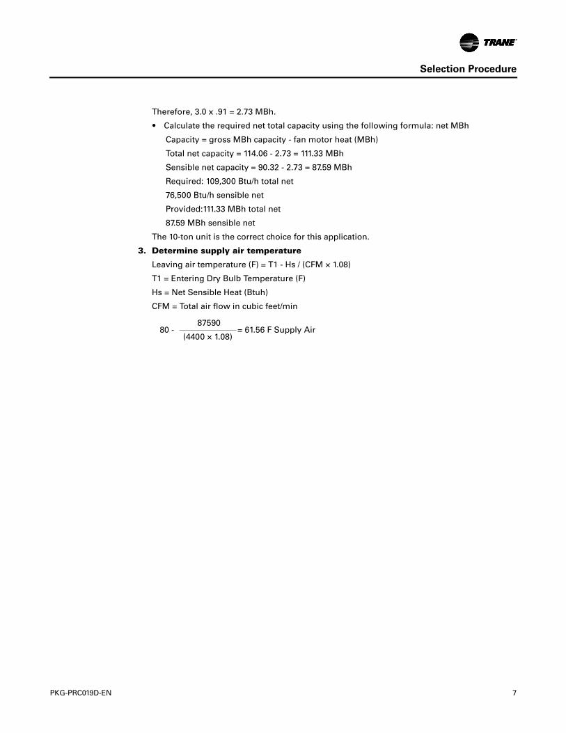
3. Determine supply air temperature
Leaving air temperature (F) = T1 - Hs / (CFM × 1.08)
T1 = Entering Dry Bulb Temperature (F)
Hs = Net Sensible Heat (Btuh)
CFM = Total air flow in cubic feet/min
80 - 87590
= 61.56 F Supply Air(4400 × 1.08)
8 PKG-PRC019D-EN
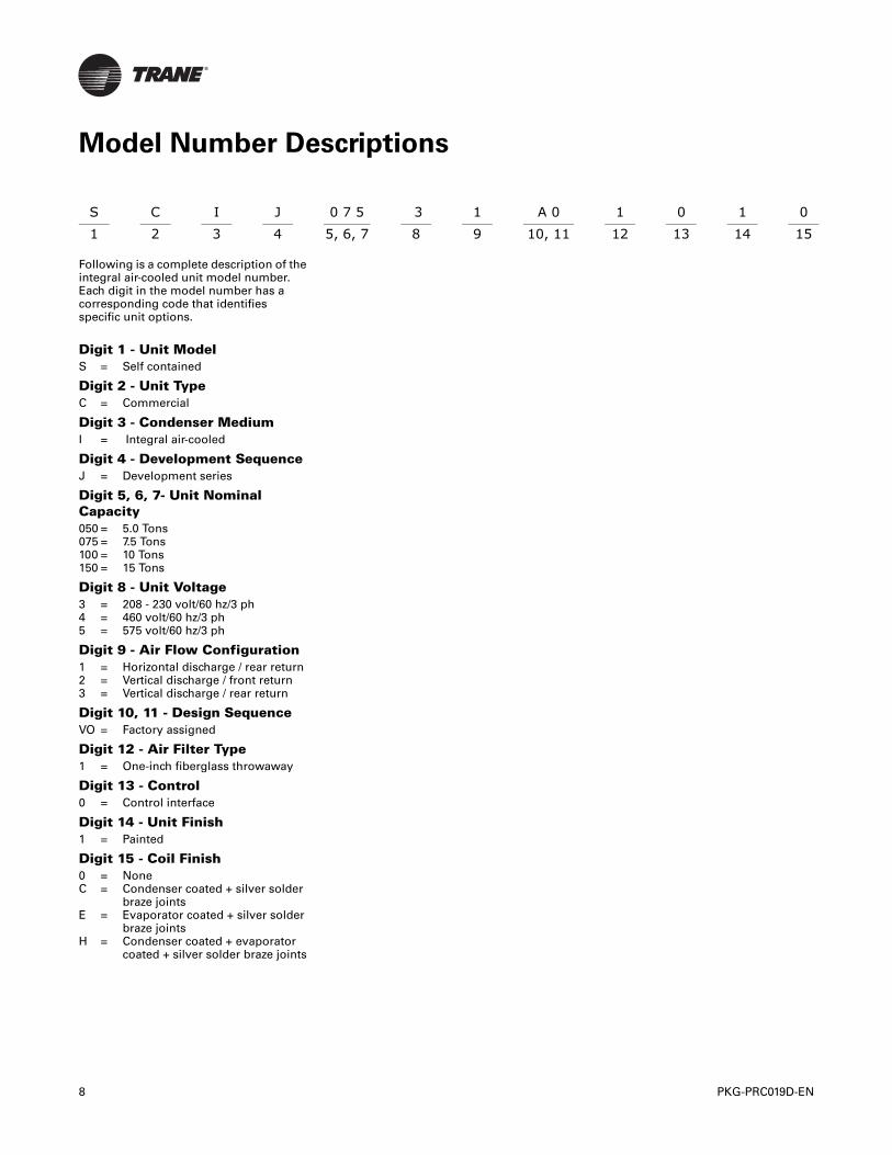
Following is a complete description of the integral air-cooled unit model number. Each digit in the model number has a corresponding code that identifies specific unit options.
Digit 1 - Unit ModelS = Self contained
Digit 2 - Unit TypeC = Commercial
Digit 3 - Condenser MediumI = Integral air-cooled
Digit 4 - Development SequenceJ = Development series
Digit 5, 6, 7- Unit Nominal Capacity050 = 5.0 Tons 075 = 7.5 Tons 100 = 10 Tons 150 = 15 Tons
Digit 8 - Unit Voltage3 = 208 - 230 volt/60 hz/3 ph4 = 460 volt/60 hz/3 ph5 = 575 volt/60 hz/3 ph
Digit 9 - Air Flow Configuration1 = Horizontal discharge / rear return2 = Vertical discharge / front return3 = Vertical discharge / rear return
Digit 10, 11 - Design SequenceVO = Factory assigned
Digit 12 - Air Filter Type1 = One-inch fiberglass throwaway
Digit 13 - Control0 = Control interface
Digit 14 - Unit Finish1 = Painted
Digit 15 - Coil Finish0 = NoneC = Condenser coated + silver solder braze jointsE = Evaporator coated + silver solder braze joints H = Condenser coated + evaporator coated + silver solder braze joints
S C I J 0 7 5 3 1 A 0 1 0 1 0 1 2 3 4 5, 6, 7 8 9 10, 11 12 13 14 15
Model Number Descriptions
PKG-PRC019D-EN 9
General Data
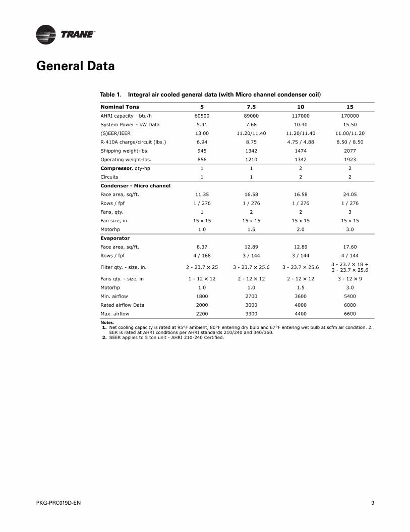
Table 1. Integral air cooled general data (with Micro channel condenser coil)
Nominal Tons 5 7.5 10 15
AHRI capacity - btu/h 60500 89000 117000 170000
System Power - kW Data 5.41 7.68 10.40 15.50
(S)EER/IEER 13.00 11.20/11.40 11.20/11.40 11.00/11.20
R-410A charge/circuit (lbs.) 6.94 8.75 4.75 / 4.88 8.50 / 8.50
Shipping weight-lbs. 945 1342 1474 2077
Operating weight-lbs. 856 1210 1342 1923
Compressor, qty-hp 1 1 2 2
Circuits 1 1 2 2
Condenser - Micro channel
Face area, sq/ft. 11.35 16.58 16.58 24.05
Rows / fpf 1 / 276 1 / 276 1 / 276 1 / 276
Fans, qty. 1 2 2 3
Fan size, in. 15 x 15 15 x 15 15 x 15 15 x 15
Motorhp 1.0 1.5 2.0 3.0
Evaporator
Face area, sq/ft. 8.37 12.89 12.89 17.60
Rows / fpf 4 / 168 3 / 144 3 / 144 4 / 144
Filter qty. - size, in. 2 - 23.7 × 25 3 - 23.7 × 25.6 3 - 23.7 × 25.6 3 - 23.7 × 18 + 2 - 23.7 × 25.6
Fans qty. - size, in 1 - 12 × 12 2 - 12 × 12 2 - 12 × 12 3 - 12 × 9
Motorhp 1.0 1.0 1.5 3.0
Min. airflow 1800 2700 3600 5400
Rated airflow Data 2000 3000 4000 6000
Max. airflow 2200 3300 4400 6600
Notes:
1. Net cooling capacity is rated at 95°F ambient, 80°F entering dry bulb and 67°F entering wet bulb at scfm air condition. 2. EER is rated at AHRI conditions per AHRI standards 210/240 and 340/360.
2. SEER applies to 5 ton unit - AHRI 210-240 Certified.

10 PKG-PRC019D-EN
Performance Data
Table 2. Air pressure drop, in. wg.
Unit Size Cfm Hot Water Coil Steam CoilThrowaway
FilterPermanent Wire Mesh
Filter
5 ton
1800
0.04 0.03
0.03 0.01
1850 0.03 0.01
1900 0.04 0.02
2000
0.06 0.05
0.05 0.03
2100 0.06 0.03
2150 0.06 0.04
2200 0.09 0.08 0.06 0.04
7.5 ton
2700
0.05 0.06
0.05 0.05
2800 0.06 0.05
2900 0.06 0.05
3000
0.06 0.06
0.06 0.05
3100 0.06 0.06
3200 0.07 0.06
3300 0.07 0.07 0.07 0.06
10 ton
3600
0.09 0.10
0.08 0.07
3750 0.08 0.08
3900 0.09 0.08
4000
0.11 0.12
0.09 0.08
4100 0.10 0.09
4250 0.10 0.09
4400 0.13 0.14 0.11 0.10
15 ton
5400
0.10 0.12
0.09 0.08
5600 0.10 0.09
5800 0.10 0.09
6000
0.12 0.14
0.11 0.10
6200 0.11 0.10
6400 0.12 0.11
6600 0.13 0.16 0.12 0.11
Table 3. Cfm capacity correction table, hot water heating coil
Cfm Compared To Rated Quanitity Heating Capacity Multiplier
Hot Water Heating
-20% 0.89
-10% 0.94
Std 1.00
+10% 1.06
+20% 1.12
PKG-PRC019D-EN 11
Performance Data
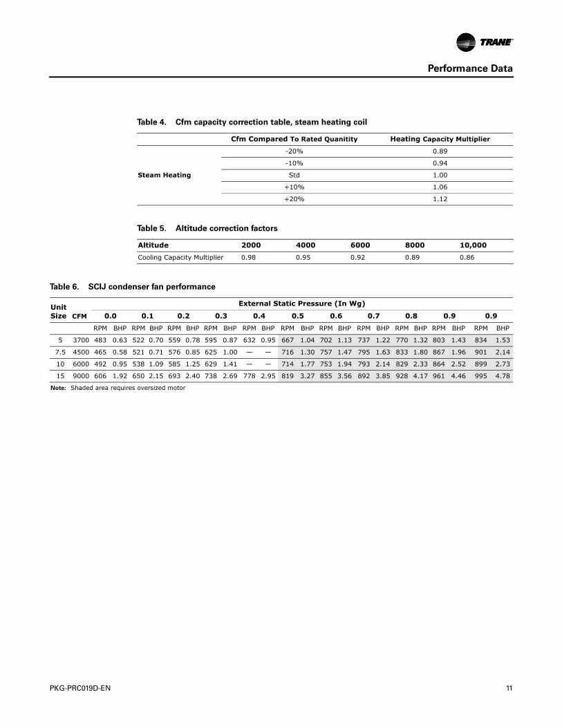
Table 4. Cfm capacity correction table, steam heating coil
Cfm Compared To Rated Quanitity Heating Capacity Multiplier
Steam Heating
-20% 0.89
-10% 0.94
Std 1.00
+10% 1.06
+20% 1.12
Table 5. Altitude correction factors
Altitude 2000 4000 6000 8000 10,000
Cooling Capacity Multiplier 0.98 0.95 0.92 0.89 0.86
Table 6. SCIJ condenser fan performance
Unit Size CFM
External Static Pressure (In Wg)
0.0 0.1 0.2 0.3 0.4 0.5 0.6 0.7 0.8 0.9 0.9
RPM BHP RPM BHP RPM BHP RPM BHP RPM BHP RPM BHP RPM BHP RPM BHP RPM BHP RPM BHP RPM BHP
5 3700 483 0.63 522 0.70 559 0.78 595 0.87 632 0.95 667 1.04 702 1.13 737 1.22 770 1.32 803 1.43 834 1.53
7.5 4500 465 0.58 521 0.71 576 0.85 625 1.00 — — 716 1.30 757 1.47 795 1.63 833 1.80 867 1.96 901 2.14
10 6000 492 0.95 538 1.09 585 1.25 629 1.41 — — 714 1.77 753 1.94 793 2.14 829 2.33 864 2.52 899 2.73
15 9000 606 1.92 650 2.15 693 2.40 738 2.69 778 2.95 819 3.27 855 3.56 892 3.85 928 4.17 961 4.46 995 4.78
Note: Shaded area requires oversized motor

12 PKG-PRC019D-EN
Performance Data
Table 7. Evaporator fan performance, external static pressure 0.1 to 0.7
Unit Size CFM
External Static Pressure (InWg)
0.1 0.2 0.3 0.4 0.5 0.6 0.7
RPM BHP RPM BHP RPM BHP RPM BHP RPM BHP RPM BHP RPM BHP
5
1800 — — 587 0.25 644 0.29 696 0.33 749 0.38 799 0.44 845 0.49
1850 — — 591 0.26 648 0.30 699 0.35 754 0.40 801 0.45 848 0.51
1900 — — 596 0.27 651 0.32 706 0.36 756 0.41 804 13.31 850 0.52
2000 — — 607 0.30 661 0.35 715 0.40 764 0.45 810 0.50 856 0.56
2100 563 0.29 619 0.33 671 0.38 723 0.43 771 0.48 817 0.54 862 0.59
2150 571 0.30 623 0.35 677 0.40 726 0.45 775 0.50 821 0.56 865 0.61
2200 576 0.32 630 0.36 681 0.41 731 0.46 778 0.52 823 0.57 868 0.63
7.5
2700 513 0.27 589 0.35 655 0.43 715 0.52 768 0.61 818 0.71 868 0.81
2800 521 0.29 593 0.37 658 0.45 719 0.54 772 0.64 823 0.74 870 0.84
2900 526 0.30 598 0.38 665 0.47 723 0.56 776 0.66 827 0.76 873 0.87
3000 531 0.32 604 0.41 668 0.50 727 0.59 782 0.69 831 0.79 878 0.90
3100 539 0.35 608 0.43 672 0.52 732 0.62 785 0.71 836 0.82 882 0.93
3200 545 0.37 615 0.45 678 0.54 735 0.64 791 0.74 840 0.85 887 0.96
3300 553 0.39 619 0.48 684 0.57 741 0.67 794 0.77 845 0.88 890 0.99
10
3600 — — 612 0.52 673 0.61 732 0.72 786 0.82 838 0.94 885 1.05
3700 — — 619 0.55 681 0.65 738 0.75 791 0.86 843 0.97 890 1.09
3800 — — 626 0.58 687 0.68 743 0.78 796 0.89 847 1.01 894 1.12
3900 — — 634 0.61 693 0.71 748 0.82 803 0.93 852 1.05 898 1.16
4000 582 0.56 643 0.65 700 0.75 756 0.86 807 0.97 856 1.08 904 1.21
4100 592 0.59 650 0.69 708 0.79 761 0.90 812 1.01 862 1.13 908 1.25
4200 601 0.63 659 0.73 714 0.83 766 0.93 819 1.05 867 1.17 914 1.30
4300 611 0.67 666 0.76 722 0.87 774 0.98 823 1.09 873 1.22 918 1.34
4400 619 0.70 676 0.81 728 0.91 781 1.02 830 1.14 877 1.26 924 1.39
15
5400 — — 693 1.03 739 1.15 785 1.28 829 1.38 872 1.51 915 1.63
5600 661 1.03 706 1.12 752 1.25 797 1.35 839 1.47 882 1.60 922 1.73
5800 676 1.09 723 1.22 766 1.35 808 1.47 851 1.60 891 1.73 932 1.86
6000 692 1.22 735 1.31 780 1.44 821 1.57 861 1.70 902 1.83 941 1.96
6200 708 1.31 751 1.44 793 1.57 834 1.70 873 1.83 913 1.96 950 2.08
6400 725 1.41 766 1.54 807 1.67 846 1.70 886 1.96 923 2.08 961 2.21
6600 741 1.54 782 1.67 821 1.80 861 1.92 897 2.08 934 2.21 972 2.37
Notes:
1. External Static Pressure considering clean construction throwaway one-inch fiberglass filter (75% average efficiency filter @ ASHRAE 52.1-1992)
2. Standard Motor - TEFC Type - Standard Drive 3. Dark gray area is Standard Motor - TEFC Type - High Static Pressure Drive Kit (Field Installed) 4. Light gray area is Oversized Motor TEFC Type - Oversized Motor Kit (Field Installed)

PKG-PRC019D-EN 13
Performance Data
Table 8. Evaporator fan performance, external static pressure 0.8 to 1.6
Unit Size CFM
External Static Pressure (InWg)
0.8 0.9 1.0 1.2 1.4 1.6
RPM BHP RPM BHP RPM BHP RPM BHP RPM BHP RPM BHP
5
1800 887 0.55 928 0.60 965 0.66 1038 0.78 1107 0.91 — —
1850 889 0.56 931 0.62 968 0.68 1040 0.80 1108 0.93 — —
1900 892 0.58 933 0.64 971 0.70 1043 0.82 1110 0.95 1175 1.08
2000 898 0.61 940 0.68 977 0.74 1049 0.86 1116 1.00 1178 1.13
2100 904 0.65 945 0.72 983 0.78 1056 0.91 1122 1.04 1184 1.18
2150 908 0.67 947 0.73 987 0.80 1058 0.93 1125 1.07 1187 1.21
2200 910 0.69 951 0.76 989 0.82 1061 0.95 1128 1.09 1190 1.23
7.5
2700 887 0.85 — — — — — — — — — —
2800 916 0.95 — — — — — — — — — —
2900 920 0.98 961 1.07 — — — — — — — —
3000 922 1.01 965 1.12 995 1.18 — — — — — —
3100 925 1.04 969 1.16 1011 1.27 — — — — — —
3200 930 1.07 972 1.19 1014 1.31 1061 1.45 — — — —
3300 935 1.11 976 1.23 1016 1.35 1094 1.60 — — — —
10
3600 929 1.17 973 1.29 1012 1.41 1089 1.67 1162 1.95 — —
3700 936 1.21 977 1.33 1017 1.46 1093 1.72 1165 2.00 — —
3800 940 1.25 982 1.37 1021 1.50 1097 1.77 1168 2.05 1237 2.34
3900 944 1.29 986 1.42 1027 1.55 1101 1.81 1171 2.10 1239 2.39
4000 948 1.33 — — 1031 1.59 1107 1.87 1177 2.15 1242 2.44
4100 954 1.38 — — 1035 1.64 1111 1.92 1180 2.21 1247 2.51
4200 958 1.42 — — 1041 1.69 1116 1.97 1184 2.26 1250 2.56
4300 963 1.47 1005 1.61 1044 1.74 1120 2.02 1190 2.32 1255 2.63
4400 967 1.52 1010 1.66 1050 1.80 1125 2.08 1195 2.38 1259 2.69
15
5400 955 1.76 997 1.89 1035 2.02 1111 2.31 1184 2.60 1252 2.88
5600 962 1.86 1002 2.02 1040 2.15 1116 2.44 1187 2.72 1256 3.01
5800 971 1.99 1009 2.12 1048 2.28 1121 2.56 1190 2.85 1258 3.14
6000 981 2.12 1017 2.24 1054 2.37 1126 2.69 1196 2.98 1263 3.30
6200 989 2.24 1026 2.37 1062 2.53 1133 2.82 1201 3.14 1267 3.43
6400 999 2.37 1035 2.50 1070 2.66 1139 2.95 1206 3.27 1272 3.59
6600 1008 2.50 1044 2.66 1079 2.82 1147 3.11 1214 3.43 1277 3.75
Notes:
1. External Static Pressure considering clean construction throwaway one-inch fiberglass filter (75% average efficiency filter @ ASHRAE 52.1-1992)
2. Standard Motor - TEFC Type - Standard Drive 3. Dark gray area is Standard Motor - TEFC Type - High Static Pressure Drive Kit (Field Installed) 4. Light gray area is Oversized Motor TEFC Type - Oversized Motor Kit (Field Installed)
14 PKG-PRC019D-EN
Performance Data
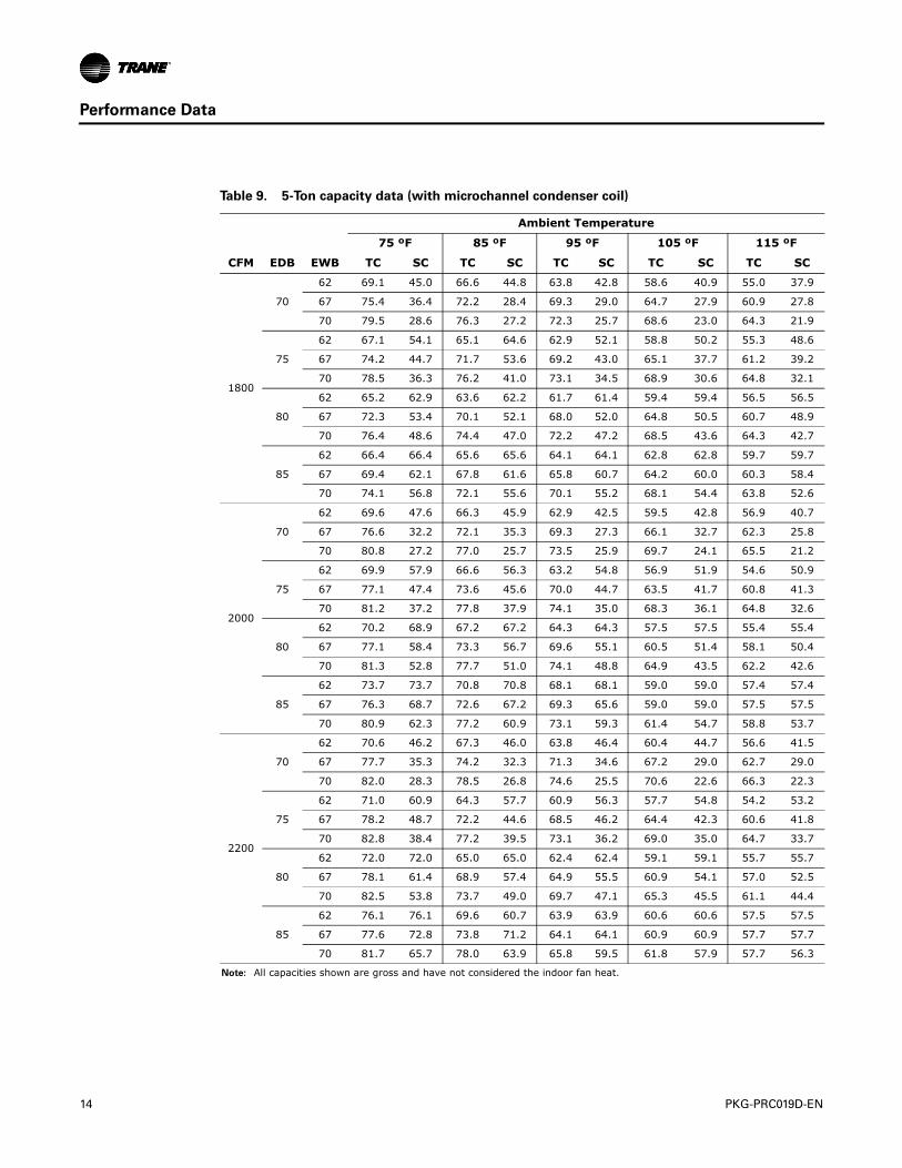
Table 9. 5-Ton capacity data (with microchannel condenser coil)
CFM EDB EWB
Ambient Temperature
75 ºF 85 ºF 95 ºF 105 ºF 115 ºF
TC SC TC SC TC SC TC SC TC SC
1800
70
62 69.1 45.0 66.6 44.8 63.8 42.8 58.6 40.9 55.0 37.9
67 75.4 36.4 72.2 28.4 69.3 29.0 64.7 27.9 60.9 27.8
70 79.5 28.6 76.3 27.2 72.3 25.7 68.6 23.0 64.3 21.9
75
62 67.1 54.1 65.1 64.6 62.9 52.1 58.8 50.2 55.3 48.6
67 74.2 44.7 71.7 53.6 69.2 43.0 65.1 37.7 61.2 39.2
70 78.5 36.3 76.2 41.0 73.1 34.5 68.9 30.6 64.8 32.1
80
62 65.2 62.9 63.6 62.2 61.7 61.4 59.4 59.4 56.5 56.5
67 72.3 53.4 70.1 52.1 68.0 52.0 64.8 50.5 60.7 48.9
70 76.4 48.6 74.4 47.0 72.2 47.2 68.5 43.6 64.3 42.7
85
62 66.4 66.4 65.6 65.6 64.1 64.1 62.8 62.8 59.7 59.7
67 69.4 62.1 67.8 61.6 65.8 60.7 64.2 60.0 60.3 58.4
70 74.1 56.8 72.1 55.6 70.1 55.2 68.1 54.4 63.8 52.6
2000
70
62 69.6 47.6 66.3 45.9 62.9 42.5 59.5 42.8 56.9 40.7
67 76.6 32.2 72.1 35.3 69.3 27.3 66.1 32.7 62.3 25.8
70 80.8 27.2 77.0 25.7 73.5 25.9 69.7 24.1 65.5 21.2
75
62 69.9 57.9 66.6 56.3 63.2 54.8 56.9 51.9 54.6 50.9
67 77.1 47.4 73.6 45.6 70.0 44.7 63.5 41.7 60.8 41.3
70 81.2 37.2 77.8 37.9 74.1 35.0 68.3 36.1 64.8 32.6
80
62 70.2 68.9 67.2 67.2 64.3 64.3 57.5 57.5 55.4 55.4
67 77.1 58.4 73.3 56.7 69.6 55.1 60.5 51.4 58.1 50.4
70 81.3 52.8 77.7 51.0 74.1 48.8 64.9 43.5 62.2 42.6
85
62 73.7 73.7 70.8 70.8 68.1 68.1 59.0 59.0 57.4 57.4
67 76.3 68.7 72.6 67.2 69.3 65.6 59.0 59.0 57.5 57.5
70 80.9 62.3 77.2 60.9 73.1 59.3 61.4 54.7 58.8 53.7
2200
70
62 70.6 46.2 67.3 46.0 63.8 46.4 60.4 44.7 56.6 41.5
67 77.7 35.3 74.2 32.3 71.3 34.6 67.2 29.0 62.7 29.0
70 82.0 28.3 78.5 26.8 74.6 25.5 70.6 22.6 66.3 22.3
75
62 71.0 60.9 64.3 57.7 60.9 56.3 57.7 54.8 54.2 53.2
67 78.2 48.7 72.2 44.6 68.5 46.2 64.4 42.3 60.6 41.8
70 82.8 38.4 77.2 39.5 73.1 36.2 69.0 35.0 64.7 33.7
80
62 72.0 72.0 65.0 65.0 62.4 62.4 59.1 59.1 55.7 55.7
67 78.1 61.4 68.9 57.4 64.9 55.5 60.9 54.1 57.0 52.5
70 82.5 53.8 73.7 49.0 69.7 47.1 65.3 45.5 61.1 44.4
85
62 76.1 76.1 69.6 60.7 63.9 63.9 60.6 60.6 57.5 57.5
67 77.6 72.8 73.8 71.2 64.1 64.1 60.9 60.9 57.7 57.7
70 81.7 65.7 78.0 63.9 65.8 59.5 61.8 57.9 57.7 56.3
Note: All capacities shown are gross and have not considered the indoor fan heat.

PKG-PRC019D-EN 15
Performance Data
Table 10. 7.5-Ton capacity data (with microchannel condenser coil)
CFM EDB EWB
Ambient Temperature
75 ºF 85 ºF 95 ºF 105 ºF 115 ºF
TC SC TC SC TC SC TC SC TC SC
2700
70
62 88.3 50.6 84.9 49.3 81.1 47.8 77.1 46.3 72.8 44.7
67 95.1 32.3 91.4 31.0 87.3 29.6 83.0 28.2 78.4 26.4
70 99.1 20.5 95.2 19.2 90.9 17.6 86.5 16.6 81.8 15.2
75
62 89.0 66.1 85.6 64.7 81.8 63.3 77.7 61.7 73.4 60.3
67 95.6 47.9 91.9 46.7 87.9 45.3 83.6 43.9 79.0 42.6
70 99.8 36.6 96.0 35.2 91.9 34.3 87.4 32.9 82.6 31.5
80
62 89.6 81.5 86.3 80.1 82.6 78.7 78.8 77.3 74.4 74.2
67 96.0 63.4 92.3 62.2 88.4 60.8 83.9 59.7 79.6 58.2
70 100.2 52.2 96.3 51.1 92.2 49.7 87.6 48.6 83.1 47.3
85
62 90.7 90.7 87.8 87.8 84.6 84.6 81.2 81.2 77.6 77.6
67 96.4 78.9 92.7 77.7 88.8 76.5 84.6 75.2 80.1 73.8
70 100.4 67.7 96.6 66.4 92.4 65.4 88.1 64.2 83.4 62.8
3000
70
62 90.2 53.1 86.6 51.7 82.7 50.3 78.5 48.7 74.0 47.2
67 96.9 32.9 93.1 31.3 88.9 30.4 84.4 28.7 79.7 27.4
70 100.9 20.1 97.0 18.8 92.6 17.5 88.0 16.0 83.1 14.7
75
62 90.7 70.0 87.3 68.9 83.4 67.4 79.2 65.8 74.8 64.3
67 97.4 50.3 93.6 48.8 89.5 47.7 85.1 46.3 80.4 44.9
70 101.7 37.7 97.7 36.6 93.5 35.4 88.9 34.1 84.0 32.6
80
62 91.6 87.2 88.2 85.8 84.5 83.8 80.1 80.0 75.7 75.7
67 97.8 67.2 94.1 66.1 90.0 64.9 85.6 63.5 80.9 62.1
70 102.0 55.2 97.9 53.9 93.9 52.7 89.2 51.5 84.4 50.1
85
62 93.6 93.6 90.6 90.6 87.3 87.3 83.8 83.8 80.0 80.0
67 98.1 84.5 94.5 83.3 90.4 82.1 86.2 80.8 81.7 79.5
70 102.1 72.4 98.5 71.4 94.1 70.0 89.5 68.8 84.8 67.5
3300
70
62 91.7 55.5 88.2 54.2 84.0 52.7 79.8 51.2 75.3 49.6
67 98.5 33.5 94.8 32.2 90.3 30.8 85.8 29.5 81.0 27.9
70 102.6 19.6 98.7 18.5 94.0 17.1 89.4 15.7 84.4 14.4
75
62 92.4 74.2 88.9 72.8 84.7 71.4 80.6 70.0 76.2 68.5
67 99.0 52.5 95.4 51.4 90.9 50.4 86.5 48.7 81.7 47.2
70 103.3 38.9 99.6 37.9 94.8 36.7 90.3 35.2 85.4 33.9
80
62 93.5 92.3 90.1 89.8 85.6 85.6 81.7 81.7 77.9 77.9
67 99.5 71.3 96.0 70.1 91.4 68.9 87.1 67.6 82.4 66.3
70 103.5 58.0 100.0 57.1 95.2 55.7 90.8 54.5 85.9 53.0
85
62 96.2 96.2 93.5 93.5 89.7 89.7 86.2 86.2 82.3 82.3
67 99.9 90.2 96.6 89.2 92.0 87.7 88.0 86.4 83.5 83.3
70 103.8 76.8 100.2 75.9 95.4 74.5 91.4 73.6 86.4 72.4
Note: All capacities shown are gross and have not considered the indoor fan heat.

16 PKG-PRC019D-EN
Performance Data
Table 11. 10-Ton capacity data (with microchannel condenser coil)
CFM EDB EWB
Ambient Temperature
75 ºF 85 ºF 95 ºF 105 ºF 115 ºF
TC SC TC SC TC SC TC SC TC SC
3600
70
62 117.9 70.7 112.6 68.5 108.0 66.2 103.0 64.5 97.4 62.2
67 126.1 46.5 120.4 44.2 115.6 42.5 110.2 40.6 104.3 38.2
70 131.5 31.2 125.4 29.2 120.3 27.2 114.6 25.2 108.4 23.0
75
62 118.4 90.9 113.0 88.7 108.5 86.8 103.6 84.8 98.1 82.6
67 126.5 67.2 120.6 64.7 115.9 63.4 110.7 61.4 104.8 59.2
70 131.6 52.1 125.1 50.0 120.4 48.4 115.0 46.5 109.1 44.9
80
62 120.2 111.5 113.6 108.5 109.5 106.5 104.9 103.6 99.5 99.3
67 128.0 88.1 120.5 85.3 115.9 83.7 110.8 81.9 105.3 79.9
70 133.2 73.4 125.2 70.7 120.5 69.0 115.1 67.6 109.4 65.5
85
62 121.6 121.6 115.3 115.3 111.7 111.7 107.6 107.6 103.0 103.0
67 128.4 108.5 120.6 105.5 116.1 103.9 111.3 102.3 105.9 100.4
70 133.4 93.9 124.9 91.1 120.3 89.6 115.2 88.0 109.5 86.2
4000
70
62 119.7 73.8 114.6 71.5 109.3 69.5 103.6 67.2 97.6 64.6
67 128.0 47.2 122.5 45.2 116.7 43.2 110.7 40.8 104.2 39.0
70 133.2 30.5 127.4 28.3 121.2 26.3 115.0 24.1 108.1 22.0
75
62 121.2 96.5 116.1 94.4 109.6 91.7 104.0 89.5 98.1 87.2
67 129.4 70.8 123.9 68.6 116.8 65.9 110.8 63.6 104.3 61.8
70 134.6 54.1 128.8 52.1 121.3 49.7 115.0 48.3 108.5 45.9
80
62 123.2 118.6 118.3 115.9 110.6 110.2 104.7 104.7 99.0 99.0
67 130.7 93.5 125.1 91.4 116.6 88.5 110.5 86.3 104.3 84.2
70 135.9 77.4 129.9 75.6 121.1 72.5 114.8 70.6 108.2 68.6
85
62 125.6 125.6 120.9 120.9 113.8 113.8 108.7 108.7 103.4 103.4
67 131.5 116.0 125.6 113.8 116.9 110.7 111.1 108.2 105.0 104.2
70 136.2 100.2 130.1 98.2 120.7 95.1 114.6 93.3 108.0 91.3
4400
70
62 121.6 77.1 116.4 74.8 110.9 72.8 105.1 70.5 98.9 68.6
67 129.9 48.1 124.3 46.3 118.4 43.8 112.2 42.0 105.5 39.8
70 135.2 30.0 129.1 27.6 122.9 25.9 116.3 23.6 109.4 21.5
75
62 121.8 101.2 116.7 99.1 111.3 96.9 105.5 94.5 99.4 92.1
67 130.0 73.4 124.3 71.1 118.4 69.0 112.2 67.0 105.7 64.9
70 135.0 55.2 129.2 53.3 122.8 51.4 116.6 49.4 109.8 47.3
80
62 125.6 124.2 117.7 117.5 111.9 111.9 106.5 106.5 101.1 101.1
67 129.7 97.5 124.1 95.7 118.2 93.6 112.2 91.6 105.5 89.4
70 137.8 81.3 129.0 78.3 122.8 76.5 116.2 74.6 109.2 72.5
85
62 126.2 126.2 121.5 121.5 116.5 116.5 111.3 111.3 105.6 105.6
67 130.2 121.7 124.5 119.5 119.1 116.8 113.0 112.4 106.0 105.9
70 134.5 104.9 128.6 103.0 122.5 101.2 116.1 99.2 109.3 97.2
Note: All capacities shown are gross and have not considered the indoor fan heat.
PKG-PRC019D-EN 17
Performance Data
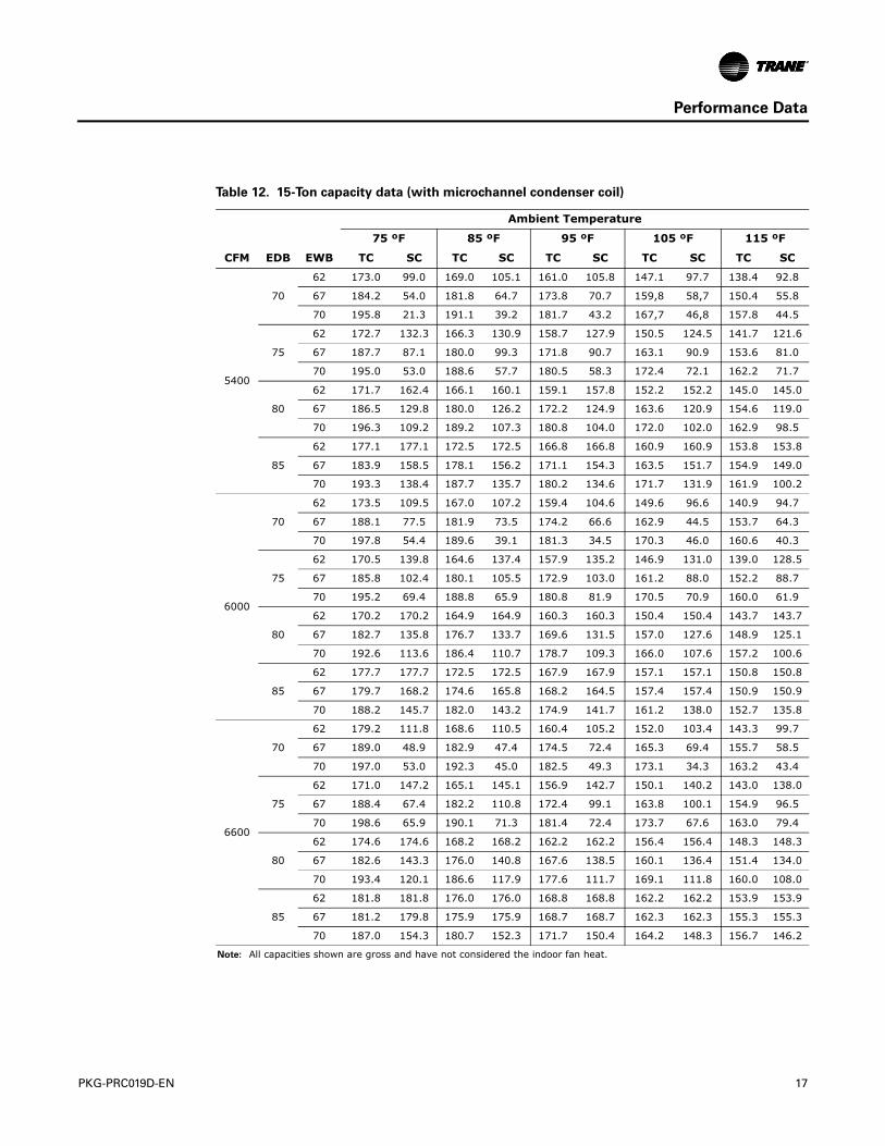
Table 12. 15-Ton capacity data (with microchannel condenser coil)
CFM EDB EWB
Ambient Temperature
75 ºF 85 ºF 95 ºF 105 ºF 115 ºF
TC SC TC SC TC SC TC SC TC SC
5400
70
62 173.0 99.0 169.0 105.1 161.0 105.8 147.1 97.7 138.4 92.8
67 184.2 54.0 181.8 64.7 173.8 70.7 159,8 58,7 150.4 55.8
70 195.8 21.3 191.1 39.2 181.7 43.2 167,7 46,8 157.8 44.5
75
62 172.7 132.3 166.3 130.9 158.7 127.9 150.5 124.5 141.7 121.6
67 187.7 87.1 180.0 99.3 171.8 90.7 163.1 90.9 153.6 81.0
70 195.0 53.0 188.6 57.7 180.5 58.3 172.4 72.1 162.2 71.7
80
62 171.7 162.4 166.1 160.1 159.1 157.8 152.2 152.2 145.0 145.0
67 186.5 129.8 180.0 126.2 172.2 124.9 163.6 120.9 154.6 119.0
70 196.3 109.2 189.2 107.3 180.8 104.0 172.0 102.0 162.9 98.5
85
62 177.1 177.1 172.5 172.5 166.8 166.8 160.9 160.9 153.8 153.8
67 183.9 158.5 178.1 156.2 171.1 154.3 163.5 151.7 154.9 149.0
70 193.3 138.4 187.7 135.7 180.2 134.6 171.7 131.9 161.9 100.2
6000
70
62 173.5 109.5 167.0 107.2 159.4 104.6 149.6 96.6 140.9 94.7
67 188.1 77.5 181.9 73.5 174.2 66.6 162.9 44.5 153.7 64.3
70 197.8 54.4 189.6 39.1 181.3 34.5 170.3 46.0 160.6 40.3
75
62 170.5 139.8 164.6 137.4 157.9 135.2 146.9 131.0 139.0 128.5
67 185.8 102.4 180.1 105.5 172.9 103.0 161.2 88.0 152.2 88.7
70 195.2 69.4 188.8 65.9 180.8 81.9 170.5 70.9 160.0 61.9
80
62 170.2 170.2 164.9 164.9 160.3 160.3 150.4 150.4 143.7 143.7
67 182.7 135.8 176.7 133.7 169.6 131.5 157.0 127.6 148.9 125.1
70 192.6 113.6 186.4 110.7 178.7 109.3 166.0 107.6 157.2 100.6
85
62 177.7 177.7 172.5 172.5 167.9 167.9 157.1 157.1 150.8 150.8
67 179.7 168.2 174.6 165.8 168.2 164.5 157.4 157.4 150.9 150.9
70 188.2 145.7 182.0 143.2 174.9 141.7 161.2 138.0 152.7 135.8
6600
70
62 179.2 111.8 168.6 110.5 160.4 105.2 152.0 103.4 143.3 99.7
67 189.0 48.9 182.9 47.4 174.5 72.4 165.3 69.4 155.7 58.5
70 197.0 53.0 192.3 45.0 182.5 49.3 173.1 34.3 163.2 43.4
75
62 171.0 147.2 165.1 145.1 156.9 142.7 150.1 140.2 143.0 138.0
67 188.4 67.4 182.2 110.8 172.4 99.1 163.8 100.1 154.9 96.5
70 198.6 65.9 190.1 71.3 181.4 72.4 173.7 67.6 163.0 79.4
80
62 174.6 174.6 168.2 168.2 162.2 162.2 156.4 156.4 148.3 148.3
67 182.6 143.3 176.0 140.8 167.6 138.5 160.1 136.4 151.4 134.0
70 193.4 120.1 186.6 117.9 177.6 111.7 169.1 111.8 160.0 108.0
85
62 181.8 181.8 176.0 176.0 168.8 168.8 162.2 162.2 153.9 153.9
67 181.2 179.8 175.9 175.9 168.7 168.7 162.3 162.3 155.3 155.3
70 187.0 154.3 180.7 152.3 171.7 150.4 164.2 148.3 156.7 146.2
Note: All capacities shown are gross and have not considered the indoor fan heat.

18 PKG-PRC019D-EN
Performance Data
Table 13. Hot water coil capacity, EWT = 180ºF
UnitSize CFM EAT
Water Temperature Drop
20 ºF 30 ºF 40 ºF
gpm MBh LAT gpm MBh LAT gpm MBh LAT
5 ton
1800
40 18.6 182.0 133.0 11.4 166.0 125.0 7.7 151.0 117.2
60 15.5 151.0 137.4 9.3 136.0 129.6 6.2 121.0 121.8
80 12.5 121.0 142.0 7.2 106.0 134.2 4.6 91.0 126.5
200
40 20.3 197.0 130.7 12.3 180.0 122.9 8.4 163.0 115.1
60 16.8 164.0 135.5 10.1 147.0 127.8 6.7 131.0 130.1
80 13.5 131.0 140.4 7.8 114.0 132.7 5.0 98.0 125.1
2200
40 21.8 212.0 128.6 13.2 193.0 120.9 9.0 175.0 113.2
60 18.1 176.0 133.8 10.8 158.0 126.1 7.2 140.0 118.5
80 14.5 141.0 139.0 8.4 123.0 131.4 3.4 105.0 123.9
7.5 ton
2700
40 28.0 280.7 135.9 17.6 264.8 130.4 12.4 247.9 124.7
60 23.6 236.2 140.7 14.7 220.1 135.2 10.1 202.9 129.3
80 19.2 191.7 145.5 11.7 175.3 139.9 7.9 157.1 133.6
3000
40 30.5 305.7 134.0 19.2 288.1 128.5 13.5 269.5 122.8
60 25.7 257.2 139.1 16.0 239.4 133.6 11.0 220.4 127.8
80 20.8 208.7 144.1 12.7 190.5 138.6 8.5 170.7 132.5
3300
40 32.9 329.7 132.1 20.7 310.4 126.7 14.5 290.1 121.1
60 27.7 277.3 137.5 17.2 257.8 132.0 11.9 237.2 126.3
80 22.5 224.9 142.8 13.7 205.1 137.3 9.2 183.7 131.3
10 ton
3600
40 35.4 354.0 130.7 22.2 332.8 125.2 15.5 310.6 119.6
60 29.7 297.6 136.2 18.4 276.3 130.8 12.7 253.8 125.0
80 24.1 241.2 141.8 14.6 219.6 136.2 9.8 196.3 130.3
4000
40 38.2 382.3 128.1 23.9 359.0 122.8 16.7 334.7 117.2
60 32.1 321.3 134.1 19.9 297.9 128.7 13.7 273.3 123.0
80 26.0 260.3 140.0 15.8 236.6 134.5 10.6 211.3 128.7
4400
40 40.9 409.1 125.7 25.6 383.8 120.4 17.9 357.4 114.9
60 34.3 343.7 132.0 21.2 318.3 126.7 14.6 291.6 121.1
80 27.8 278.3 138.3 16.8 252.6 132.9 11.3 225.3 127.2
15 ton
5400
40 52.5 525.7 129.8 33.2 498.1 125.0 23.5 469.1 120.1
60 44.2 443.0 135.6 27.7 415.1 130.9 19.3 385.5 125.8
80 36.0 360.2 141.5 22.1 331.8 136.7 15.1 301.4 131.5
6000
40 56.8 568.6 127.4 35.9 538.2 122.7 25.3 506.4 117.8
60 47.8 479.0 133.6 29.9 448.3 128.9 20.8 415.9 123.9
80 38.9 389.3 139.8 23.9 358.1 135.0 16.2 324.8 129.9
6600
40 60.8 609.1 125.1 38.4 576.1 120.5 27.1 541.6 115.7
60 51.2 513.0 131.7 32.0 479.7 127.0 22.2 444.6 122.1
80 41.6 416.8 138.2 25.5 383.0 133.5 17.3 347.0 128.5

PKG-PRC019D-EN 19
Performance Data
Table 14. Hot water coil capacity, EWT = 200ºF
UnitSize CFM EAT
Water Temperature Drop
20 ºF 30 ºF 40 ºF
gpm MBh LAT gpm MBh LAT gpm MBh LAT
5 ton
1800
40 22.0 213.0 149.0 13.6 198.0 141.3 9.4 183.0 133.5
60 18.8 183.0 153.4 11.5 168.0 145.8 7.8 153.0 138.1
80 15.7 152.0 157.9 9.4 137.0 153.3 6.3 122.0 142.7
200
40 23.8 231.0 146.4 14.7 215.0 138.7 10.2 198.0 131.1
60 20.4 198.0 151.2 12.5 182.0 143.6 8.5 165.0 136.0
80 17.0 165.0 156.0 10.2 149.0 148.5 6.8 132.0 140.9
2200
40 25.6 249.0 144.0 15.8 231.0 136.4 10.9 212.0 128.8
60 22.0 213.0 149.2 13.4 195.0 141.5 9.1 177.0 134.1
80 18.3 178.0 157.3 11.0 160.0 146.8 7.3 142.0 139.4
7.5 ton
2700
40 32.5 326.3 151.4 20.7 311.1 146.2 14.7 295.2 140.8
60 28.1 281.8 156.2 17.7 266.5 151.0 12.5 250.4 145.5
80 23.7 237.4 161.1 14.8 221.9 155.8 10.2 205.4 150.1
3000
40 35.4 355.4 149.2 22.5 338.6 144.1 16.0 321.0 138.7
60 30.6 307.0 154.3 19.3 290.0 149.1 13.6 272.2 143.7
80 25.8 258.5 159.4 16.0 241.3 154.2 11.1 223.1 148.6
3300
40 38.2 383.4 147.1 24.3 365.0 142.0 17.3 345.8 136.6
60 33.0 331.1 152.5 20.8 312.5 147.3 14.6 293.0 141.9
80 27.8 278.7 157.9 17.3 259.9 152.6 12.0 240.1 147.1
10 ton
3600
40 41.0 411.8 145.5 26.0 391.6 140.3 18.5 370.6 134.9
60 35.4 355.5 151.1 22.3 335.2 145.8 15.7 313.9 140.4
80 29.8 299.1 156.6 18.5 278.6 151.4 12.8 257.0 145.8
4000
40 44.3 445.0 142.6 28.1 422.7 137.4 19.9 399.6 132.1
60 38.3 384.0 148.5 24.0 361.7 143.4 16.9 338.3 138.0
80 32.2 323.0 154.5 20.0 300.5 149.3 13.8 276.8 143.8
4400
40 47.5 476.3 139.8 30.0 452.0 134.7 21.3 427.0 129.5
60 40.9 410.9 146.1 25.7 386.6 141.0 18.0 361.3 135.7
80 34.4 345.5 152.4 21.3 321.1 147.3 14.7 295.4 141.9
15 ton
5400
40 60.8 610.1 144.2 38.8 583.5 139.6 27.7 555.9 134.9
60 52.6 527.4 150.1 33.3 500.6 145.5 23.6 472.6 140.7
80 44.3 444.7 155.9 27.8 417.6 151.3 19.4 389.1 146.4
6000
40 65.8 660.0 141.4 41.9 630.7 136.9 30.0 600.4 132.3
60 56.8 570.4 147.7 36.0 541.0 143.1 25.5 510.3 138.4
80 47.9 480.8 153.9 30.0 451.1 149.3 20.9 419.8 144.5
6600
40 70.5 707.3 138.8 44.9 675.4 134.4 32.1 642.5 129.8
60 60.9 611.2 145.4 38.5 579.2 140.9 27.2 545.8 136.3
80 51.3 515.0 151.9 32.1 482.7 147.4 22.4 448.8 142.7
20 PKG-PRC019D-EN
Performance Data
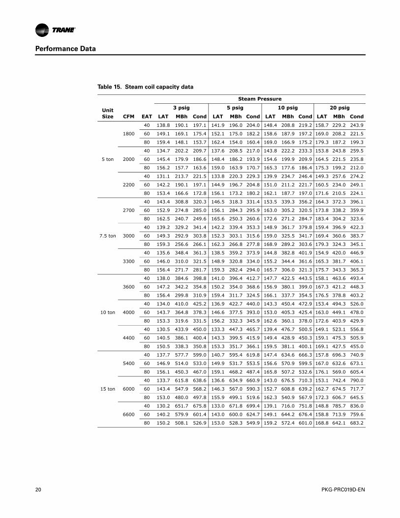
Table 15. Steam coil capacity data
Steam Pressure
UnitSize
3 psig 5 psig 10 psig 20 psig
CFM EAT LAT MBh Cond LAT MBh Cond LAT MBh Cond LAT MBh Cond
5 ton
1800
40 138.8 190.1 197.1 141.9 196.0 204.0 148.4 208.8 219.2 158.7 229.2 243.9
60 149.1 169.1 175.4 152.1 175.0 182.2 158.6 187.9 197.2 169.0 208.2 221.5
80 159.4 148.1 153.7 162.4 154.0 160.4 169.0 166.9 175.2 179.3 187.2 199.3
2000
40 134.7 202.2 209.7 137.6 208.5 217.0 143.8 222.2 233.3 153.8 243.8 259.5
60 145.4 179.9 186.6 148.4 186.2 193.9 154.6 199.9 209.9 164.5 221.5 235.8
80 156.2 157.7 163.6 159.0 163.9 170.7 165.3 177.6 186.4 175.3 199.2 212.0
2200
40 131.1 213.7 221.5 133.8 220.3 229.3 139.9 234.7 246.4 149.3 257.6 274.2
60 142.2 190.1 197.1 144.9 196.7 204.8 151.0 211.2 221.7 160.5 234.0 249.1
80 153.4 166.6 172.8 156.1 173.2 180.2 162.1 187.7 197.0 171.6 210.5 224.1
7.5 ton
2700
40 143.4 308.8 320.3 146.5 318.3 331.4 153.5 339.3 356.2 164.3 372.3 396.1
60 152.9 274.8 285.0 156.1 284.3 295.9 163.0 305.2 320.5 173.8 338.2 359.9
80 162.5 240.7 249.6 165.6 250.3 260.6 172.6 271.2 284.7 183.4 304.2 323.6
3000
40 139.2 329.2 341.4 142.2 339.4 353.3 148.9 361.7 379.8 159.4 396.9 422.3
60 149.3 292.9 303.8 152.3 303.1 315.6 159.0 325.5 341.7 169.4 360.6 383.7
80 159.3 256.6 266.1 162.3 266.8 277.8 168.9 289.2 303.6 179.3 324.3 345.1
3300
40 135.6 348.4 361.3 138.5 359.2 373.9 144.8 382.8 401.9 154.9 420.0 446.9
60 146.0 310.0 321.5 148.9 320.8 334.0 155.2 344.4 361.6 165.3 381.7 406.1
80 156.4 271.7 281.7 159.3 282.4 294.0 165.7 306.0 321.3 175.7 343.3 365.3
10 ton
3600
40 138.0 384.6 398.8 141.0 396.4 412.7 147.7 422.5 443.5 158.1 463.6 493.4
60 147.2 342.2 354.8 150.2 354.0 368.6 156.9 380.1 399.0 167.3 421.2 448.3
80 156.4 299.8 310.9 159.4 311.7 324.5 166.1 337.7 354.5 176.5 378.8 403.2
4000
40 134.0 410.0 425.2 136.9 422.7 440.0 143.3 450.4 472.9 153.4 494.3 526.0
60 143.7 364.8 378.3 146.6 377.5 393.0 153.0 405.3 425.4 163.0 449.1 478.0
80 153.3 319.6 331.5 156.2 332.3 345.9 162.6 360.1 378.0 172.6 403.9 429.9
4400
40 130.5 433.9 450.0 133.3 447.3 465.7 139.4 476.7 500.5 149.1 523.1 556.8
60 140.5 386.1 400.4 143.3 399.5 415.9 149.4 428.9 450.3 159.1 475.3 505.9
80 150.5 338.3 350.8 153.3 351.7 366.1 159.5 381.1 400.1 169.1 427.5 455.0
15 ton
5400
40 137.7 577.7 599.0 140.7 595.4 619.8 147.4 634.6 666.3 157.8 696.3 740.9
60 146.9 514.0 533.0 149.9 531.7 553.5 156.6 570.9 599.5 167.0 632.6 673.1
80 156.1 450.3 467.0 159.1 468.2 487.4 165.8 507.2 532.6 176.1 569.0 605.4
6000
40 133.7 615.8 638.6 136.6 634.9 660.9 143.0 676.5 710.3 153.1 742.4 790.0
60 143.4 547.9 568.2 146.3 567.0 590.3 152.7 608.8 639.2 162.7 674.5 717.7
80 153.0 480.0 497.8 155.9 499.1 519.6 162.3 540.9 567.9 172.3 606.7 645.5
6600
40 130.2 651.7 675.8 133.0 671.8 699.4 139.1 716.0 751.8 148.8 785.7 836.0
60 140.2 579.9 601.4 143.0 600.0 624.7 149.1 644.2 676.4 158.8 713.9 759.6
80 150.2 508.1 526.9 153.0 528.3 549.9 159.2 572.4 601.0 168.8 642.1 683.2
PKG-PRC019D-EN 21
Electrical Data
Electrical Data Calculations
RLA = Rated Load Amps
Compressor LRA = Locked Rotor Amps
Fan Motor LRA = Locked Rotor Amps, N.E.C. Table 430 - 151
FLA = Full Load Amps, N.E.C. Table 430 - 150
Voltage utilization range is ±10 percent
Determination of Minimum Circuit Ampacity (MCA)
MCA = 1.25 × largest motor amps (FLA or RLA) + the sum of the remaining motor amps.
Determination of Maximum Fuse Size (MFS)
MFS = 2.25 × largest motor amps (FLA or RLA) + the sum of the remaining motor amps.
If the rating value determined does not equal a standard current rating of over current protective device, use the next lower standard rating for the marked maximum rating.
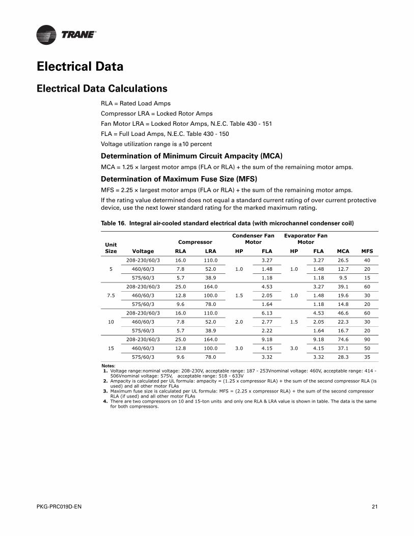
Table 16. Integral air-cooled standard electrical data (with microchannel condenser coil)
UnitSize Voltage
CompressorCondenser Fan
MotorEvaporator Fan
Motor
MCA MFSRLA LRA HP FLA HP FLA
5
208-230/60/3 16.0 110.0
1.0
3.27
1.0
3.27 26.5 40
460/60/3 7.8 52.0 1.48 1.48 12.7 20
575/60/3 5.7 38.9 1.18 1.18 9.5 15
7.5
208-230/60/3 25.0 164.0
1.5
4.53
1.0
3.27 39.1 60
460/60/3 12.8 100.0 2.05 1.48 19.6 30
575/60/3 9.6 78.0 1.64 1.18 14.8 20
10
208-230/60/3 16.0 110.0
2.0
6.13
1.5
4.53 46.6 60
460/60/3 7.8 52.0 2.77 2.05 22.3 30
575/60/3 5.7 38.9 2.22 1.64 16.7 20
15
208-230/60/3 25.0 164.0
3.0
9.18
3.0
9.18 74.6 90
460/60/3 12.8 100.0 4.15 4.15 37.1 50
575/60/3 9.6 78.0 3.32 3.32 28.3 35
Notes:
1. Voltage range:nominal voltage: 208-230V, acceptable range: 187 - 253Vnominal voltage: 460V, acceptable range: 414 - 506Vnominal voltage: 575V, acceptable range: 518 - 633V
2. Ampacity is calculated per UL formula: ampacity = (1.25 x compressor RLA) + the sum of the second compressor RLA (is used) and all other motor FLAs
3. Maximum fuse size is calculated per UL formula: MFS = (2.25 x compressor RLA) + the sum of the second compressor RLA (if used) and all other motor FLAs
4. There are two compressors on 10 and 15-ton units and only one RLA & LRA value is shown in table. The data is the same for both compressors.

22 PKG-PRC019D-EN
Electrical Data
Table 17. Integral air-cooled oversized electrical data (with microchannel condenser coil)
UnitSize Voltage
CompressorCondenser Fan Motor
Evaporator Fan Motor
Evaporator 2-Speed Motor
RLA LRA HP FLA HP FLA MCA HP FLA MCA MFS
5
208-230/60/3 16.0 110.0
2.0
6.13
1.5
4.53 30.6
N/A
45
460/60/3 7.8 52.0 2.77 2.05 14.5 20
575/60/3 5.7 38.9 2.22 1.64 11.0 15
7.5
208-230/60/3 25.0 164.0
2.0
6.13
1.5
4.53 41.9
N/A
60
460/60/3 12.8 100.0 2.77 2.05 20.8 30
575/60/3 9.6 78.0 2.22 1.64 15.9 25
10
208-230/60/3 16.0 110.0
3.0
9.18
3.0
9.18 54.3
3.0
8.92 54.0 70
460/60/3 7.8 52.0 4.15 4.15 25.8 4.46 26.1 30
575/60/3 5.7 38.9 3.32 3.32 19.5 3.57 19.7 25
15
208-230/60/3 25.0 164.0
5.0
15.00
5.0
15.00 86.3
5.0
14.9 86.2 110
460/60/3 12.8 100.0 6.80 6.80 42.4 7.45 43.1 50
575/60/3 9.6 78.0 5.44 5.44 32.5 5.96 33.0 40

PKG-PRC019D-EN 23
Dimensions and Weights
Table 18. Unit dimensions (with microchannel condenser coil), in-lbs.
Unit Size A B C D E Ship. Wgt.Oper. Wgt.
5 ton 56.69 20.63 20.63 18.92 18.92 945 856
7.5 ton — — — — — 1342 1210
10 ton — — — — — 1474 1342
15 ton — — — — — 2077 1923
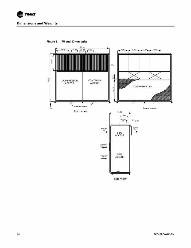
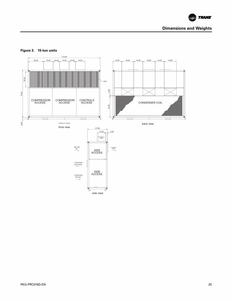
Note: 7.5-ton and 10-ton in Figure 2, p. 24, 10 and 15-ton in Figure 3, p. 25
Figure 1. 5-ton unit
CONDENSER COIL
FORKLIFT ACCESS2.76
74.8
0
24.9
0
AB C15.43 D 18.86 E
2.76
74.8
0
24.9
034
.25
0.75
back viewfront view
side view
CONDENSER RETURN
RETURN AIR
SIDE ACCESS
SIDE ACCESS
SUPPLY AIR
SUPPLY AIR
CONDENSERDISCHARGE
31.50
13.64
2.74
24 PKG-PRC019D-EN
Dimensions and Weights
Figure 2. 7.5 and 10-ton units
COMPRESSOR ACCESS
CONTROLS ACCESS
GRILL
FORKLIFT ACCESS
CONDENSER COIL
2.68
74.8
0
24.9
0
85.83
22.70 15.20 10.03 15.20 16.67 18.86 14.77 18.86
34.2
50.
75
back viewfront view
side view
CONDENSER RETURN
RETURN AIR
SIDE ACCESS
SIDE ACCESS
SUPPLY AIR
SUPPLY AIR
CONDENSERDISCHARGE
31.50
13.64
2.74
PKG-PRC019D-EN 25
Dimensions and Weights
Figure 3. 15-ton units
114,00
15,50 15,5010,00 10,00 15,5024,00 19,50 19,5014,50 14,50 19,5013,50
75,00
3,00
25,00
34,50
0,50
COMPRESSORACCESS
COMPRESSORACCESS
CONTROLSACCESS CONDENSER COIL
FORKLIFT ACESS back viewfront view
GRILL
31,50
13,50 2,50
SIDEACCESS
SIDEACCESS
RETURNAIR
CONDENSERDISCHARGE
CONDENSERRETURN
SUPPLYAIR
SUPPLYAIR
side view
26 PKG-PRC019D-EN
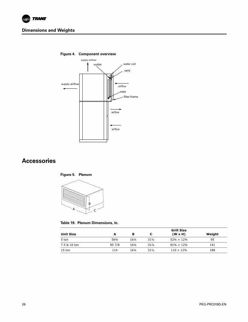
Dimensions and Weights
Accessories
Figure 4. Component overview
vent
inlet
filter frame
Figure 5. Plenum
Table 19. Plenum Dimensions, in.
Unit Size A B CGrill Size (W x H) Weight
5 ton 56¾ 16¼ 31½ 52¾ × 12¾ 95
7.5 & 10 ton 85 7/8 16¼ 31½ 81¾ × 12¾ 141
15 ton 114 16¼ 31½ 110 × 12¾ 188
B
A C
PKG-PRC019D-EN 27
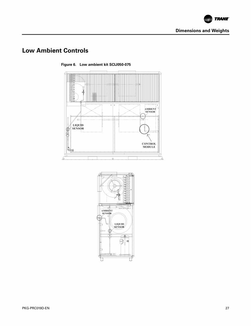
Dimensions and Weights
Low Ambient Controls
Figure 6. Low ambient kit SCIJ050-075
CONTROLMODULE
LIQUIDSENSOR
LIQUIDSENSOR
AMBIENTSENSOR
AMBIENTSENSOR

28 PKG-PRC019D-EN
Dimensions and Weights
Figure 7. Low ambient kit SCIJ100-150
LIQUIDSENSOR
AMBIENTSENSOR
CONTROLMODULE
LIQUIDSENSOR
AMBIENTSENSOR
PKG-PRC019D-EN 29
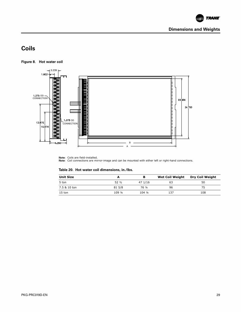
Dimensions and Weights
Coils
Note: Coils are field-installed.Note: Coil connections are mirror-image and can be mounted with either left or right-hand connections.
Figure 8. Hot water coil
3.239
ODCONNECTION
CONNECTIONOD
A
B
Table 20. Hot water coil dimensions, in./lbs.
Unit Size A B Wet Coil Weight Dry Coil Weight
5 ton 52 ½ 47 1/16 63 50
7.5 & 10 ton 81 5/8 76 ¼ 96 75
15 ton 109 ¼ 104 ¼ 137 108
30 PKG-PRC019D-EN
Dimensions and Weights
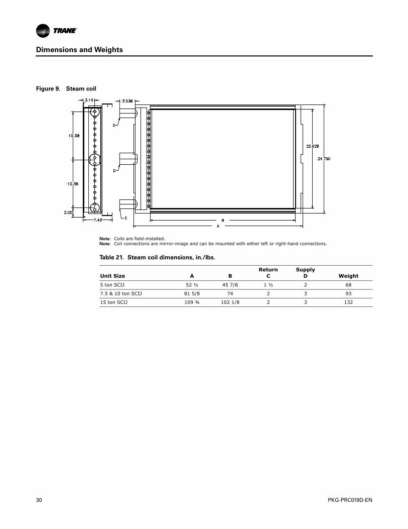
Note: Coils are field-installed.Note: Coil connections are mirror-image and can be mounted with either left or right-hand connections.
Figure 9. Steam coil
Table 21. Steam coil dimensions, in./lbs.
Unit Size A BReturn
CSupply
D Weight
5 ton SCIJ 52 ½ 45 7/8 1 ½ 2 68
7.5 & 10 ton SCIJ 81 5/8 74 2 3 93
15 ton SCIJ 109 ¾ 102 1/8 2 3 132
PKG-PRC019D-EN 31
Mechanical Specifications
General
The units shall be completely factory assembled, tested, piped, internally wired, and fully charged with R-410A. Units are in compliance with ASHRAE 90.1 equipment efficiency requirements. All units shall go through a factory run-test before shipment. All equipment shall have factory-installed decals and labels to aid in servicing and indicate caution areas.
Cabinet
The cabinet shall be constructed with galvanized steel with aluminum channels. All exterior panels shall be 24 gage, 1" double wall, foamed panels with allen-head fasteners for easy removal and access. All panels shall be painted with anti-corrosive primer and high resistance synthetic enamel. The unit shall be constructed for vertical discharge with front or rear return.
Return Air Grill
A decorative return air grill shall be provided and shall be anodized aluminum with vertical blades.
Discharge Plenum
The discharge plenum shall allow air discharge either vertically or horizontally. The plenum will be constructed to match the unit.
Evaporator and Condenser Coils
The evaporator coil shall be constructed with 3/8" OD for the, internally enhanced copper tubes, which are mechanically bonded to aluminum fins. The condenser coils are a microchannel construction—all aluminum with brazed fins and headers. Coils shall be factory leak tested to 450 psig. The drain pan shall be constructed of galvanized steel and positively sloped.
Fans
The evaporator and condenser fans shall be forward curve centrifugal fans, constructed of galvanized steel, that are statically and dynamically balanced. The fans shall be provided with permanently lubricated bearings with a design life (L10) of at least 200,000 hours.
Motors shall be open drip proof. Drive assemblies shall consist of V-belts, variable pitch drive sheaves for both the evaporator and condensers.
Filters
Units shall come standard with one-inch, fiberglass throwaway filters. The filter rack can accommodate a one-inch or two-inch filter.
Compressors
The compressors shall all be scroll compressors each with their own independent circuit. Compressors shall be mounted on rubber isolators for vibration isolation. The 5 and 7-ton units shall have a single compressor. The 10 and 15-ton units shall have dual compressors.
Refrigeration Circuit
Refrigeration circuits shall be independent and completely piped including: filter driers, distributors, and thermal expansion valves. Each circuit shall be equipped with high and low pressure switches. The high pressure switch shall be rated at 650 +/- 10 psig / 550 +/- 10 psig and the low pressure switch shall be rated at 51 +/-7 / 94 +/- 7 psig. Each circuit shall be leak tested, dehydrated and charged with oil and R-410A refrigerant at the factory.
Electrical/Controls
Each unit shall have single point power connections with a terminal block. The unit shall come standard with a control interface that will include terminal strip and 24V transformer.

32 PKG-PRC019D-EN
Mechanical Specifications
Factory-Provided Options
Evaporator and Condenser Coils with Corrosion Resistant Treatment and Silver Solder
Braze Joints. Phenolic coating applied to evaporator and condenser coils for protection in harsh environments. Silver solder braze joints are provided on coils and refrigerant piping with coated coil options.
Horizontal Discharge. The units shall be constructed to provide horizontal discharge with a rear return.
Field-Installed Accessories
Thermostats. A 1H/1C remote mounted thermostat shall be provided with 5 and 7.5-ton units. A 2H/2C or 2C remote mounted thermostat shall be provided with 10 and 15-ton units. All thermostats are available with auto, manual, or auto/manual bases.
Programmable Thermostat. A 1H/1C remote mounted programmable thermostat shall be provided with 5 and 7.5-ton units. A 2H/2C remote mounted programmable thermostat shall be provided with 10 and 15-ton units.
Low Ambient Control . A low ambient head pressure control kit shall allow unit operation down to 0°F (-17.8°C) ambient. The kit shall include low pressure cut-out bypass timers, damper actuator, mounting hardware and an installation/operation manual for field installation.
Hot Water Coil. The hot water coil shall be designed for use with 180°F to 200°F water. The hot water coil shall be a field-installed item. The coil shall be mountable to the unit with right or lest hand connections. The unit filter rack shall mount to the coil on the air inlet side.
Steam Coil. field-installed steam coil designed for use with 3, 5, 10, or 20 psig steam. The coil shall be mounted to the unit with right and left hand connections. Unit filter rack mounts to coil on air inlet side.
Filters. Two-inch pleated or permanent filters shall be provided for field installation.
Discharge Plenum. The discharge plenum shall allow air to discharge horizontally. The plenum shall be constructed of 20 gauge sheet metal with 1" fiberglass insulation to match the unit.
Low Ambient Kit. The low ambient operation kit consists of an electronic control module, an outdoor ambient temperature sensor, and liquid line temperature sensor(s). This is a simple on/off control that cycles the condenser fan(s) to maintain a liquid line temperature set point. Unit will cool down to 0°F (zero degrees) ambient temperature. The fan will only cycle when the ambient temperature is below 70°F.
Oversized/2-Speed Motor Kit. Oversized/2-speed motor kit and drives shall be provided for those applications where external static pressure exceeds the capability of the standard fan motor. The 2-speed motor reduces energy consumption of the equipment when the system is at part load conditions. Approximate turn down ratio on the 2-speed motor is 66% rated. Oversized/2-speed motors shall be totally enclosed fan-cooled (TEFC) type.
Note: The 2-speed motor kit is optional and available only on 10 and 15 ton units.
Trane optimizes the performance of homes and buildings around the world. A business of Ingersoll Rand, the leader increating and sustaining safe, comfortable and energy efficient environments, Trane offers a broad portfolio of advancedcontrols and HVAC systems, comprehensive building services, and parts. For more information, visit www.Trane.com.
Trane has a policy of continuous product and product data improvement and reserves the right to change design and specifications without notice.
We are committed to using environmentally
conscious print practices that reduce waste.
© 2015 Trane. All rights reserved.
PKG-PRC019D-EN 17 Jun 2015
Supersedes PKG-PRC019C-EN (29 Jan 2014)