product catalogue - metstrade
TRANSCRIPT

Product CatalogueProduct Catalogue

ZINTAS is an international chain processing company which founded at the end of 1970’s with the vision of becoming a global brand based on the belief in the power of high technology and continuous improvement
ZINTAS manufactures industrial chains that are used worldwide for mining and conveying, high-
alloyed G100 chains for moving and lifting, hoisting and stud and studless chains for marine industry,
high alloyed calibrated chains for agriculture industry, high wear and temperature resistant specially
designed chains for cement industry, specially designed chains for forestry, snow chains, transmission
chains and chain accessories exporting to more than 30 countries today. The ZINTAS factory ground
covers a total area of 25.000 square meters of which approximately 10.000 square meters are built
on and consists of technologically advanced 125 machines The customer satisfaction is the result of
our appropriate pricing policy and high quality standards.
ZINTAS Co. was the first organization in Turkey that has certified its chain manufacturing according
to the international standard ISO 9001 Quality Management System Certification in 1996.
ZINTAS Co. guarantees high quality products and services with over 35 years’ experience, reliability,
versatility and developing production technology.
ZINTAS Co. acts with the consciousness of the quality target based on the principle of customer
satisfaction, environmentally friendly production processes and recyclable raw materials and
products. Over 35 years ZINTAS Company has served its customers with its successful, dynamic,
flexible employees. As a reflection of our corporate culture, all of our employees behave and think
as a part of chain link, and always challenge to be the most powerful chain link of the whole system
and aware of the priority of their responsibilities.
Company Profile
1

“The chain is only as strong as its weakest link.”
Our goal is to improve and perfect each process step
starting from supply of raw materials until placing on
the market. To provide this, every process and product is
subjected to accurate and comprehensive control process
and test according to our quality management system
and international standards.
The quality management system is our guiding principle
for the reliability of our products. Certificates that we
received from both regional and international institutions
are the basis of our quality system approach.
A continuous interest in our customer needs, demonstrated amongst others by the development and production of several “tailor made” special chains.
We are an independent family business since 1979 and a reliable business partner. We cooperate with our customers and suppliers in a true in a true collaboration and pursuance of mutual success. Our Customer Relationship Management is an essential, extensive and sensitive to maintain our customer relationship permanently. Our customer-oriented strategy is based on customer satisfaction with our high quality products and services.
Quality
Customer Relations & Reliabilty
“The chain is only as strong as its weakest link.”
2 3

Zintaş in Press
4 5

Steels For Chains
Industrial steels for chains are chosen specifically for applications of mining, conveying, moving, lifting,
hoisting and marine, agriculture industry, forestry and snow chains.
Round steel link chains are used for the moving, conveying and securing of large loads. They can be
found in extraction plants in mining, as lifting appliances for cranes, during the conveyance of bulk
materials, as anchor chains in shipbuilding and for securing of cargo. Round steel link chains include
the corresponding chain components such as chain connectors, etc. Non-alloyed, alloyed steels, low
carbon, and special types of modern steels are base materials for the manufacture of round steel link
chains and chain components up to Grade 100. They are specified as technical delivery conditions in DIN
17115/2012-07 (TS 2835/1977) standard, namely with regard to the manufacture, delivery condition,
chemical composition and their mechanical characteristics and technological features.
The constitution and structure of all steels and iron starts with iron-carbon equilibrium diagram lightens
the principle of heat treatment of the chains. There are important temperatures or critical points in the
diagram.
A1: Temperature at which the eutectic reaction occurs (723 °C)
A3: Temperature when α-iron transforms to γ-iron (for pure iron 910 °C,
but the transformation temperature is progressively lowered by addition of carbon)
A4: Temperature at which γ-iron transforms to δ-iron (for pure iron 1390 °C, but the
transformation temperature is raised by addition of carbon)
A2: Curie point when iron changes from the ferro- to paramagnetic condition
(769 °C for pure iron, but no change in crystal struc-
ture is involved)
The diagram is based on the transformation that occurs
as a result of slow heating. However the fast heating and
cooling rates encountered in welding will have a signif-
icant influence on these temperatures, making the ac-
curate prediction of weld metallurgy using this diagram
is difficult.
Heat treatment process after welding requires a pro-
fessional infrastructure and specialized systems. ZINTAS
Co. performs chain quenching & tempering and case
hardening processes that require different techniques
for different applications in-plant. Thus, while maintaining the toughness and ductility of the core, the
mechanical properties are brought to the optimum level.
The Effects Of Alloying Elements On Steel Welds
Alloying elements are added to reinforce the mechanical properties of steels used in chain production.
Low-alloyed, alloyed, low carbon and special modern steels are used in chain production due to different
types of chain applications and load conditions.
Appropriate and correct raw material selection is crucial in the beginning of chain production process.
The process fails unless the election is not done professionally. The material selection belongs to the
properties of chains such as high strength for lifting, conveying and moving applications, wear-resistant
applications for mining and agriculture industry, high corrosion resistance applications for marine
industry, capability of heat treatment and case hardening, etc. Manufacturing of chains requires advanced
technology to produce chains of high properties. For the raw material supply, ZINTAS Co. cooperates and
works with well-known and professional companies in Turkey, which also provides products abroad.
Stress Strain Curve
Chain links can be deformed by subjecting external loads. The recovery of the original dimensions of
deformed body when the load is removed is known as elastic behavior. The limiting load beyond which
the material no longer behaves elastically is the elastic limit. If the elastic limit is exceeded, the body will
experience a permanent set or deformation when the load is removed off the chain links is said to have
plastic deformation. As long as the load does not exceed the elastic limit, the deformation is proportional
to the load, that states stress is proportional to strain.
OA : Elastic region within which Hooke’s law is obeyed.
A : Elastic limit, defined as the greatest stress that the metal can withstand without experien
cing a permanent strain when the load is removed.
A’ : The determination of the elastic limit is dependent on the sensitivity of the strain measu
ring instrument and replaced by the proportional limit. The proportional limit is the stress
at which the stress-strain curve deviates from linearity. The slope of the stress-strain curve
is the modulus of elasticity.
B : For engineering purposes the limit of usable elastic behavior is the yield strength which is
defined as the stress which will produce a small amount of permanent deformation,
generally equal to a strain of 0.002.
0C : Permanent strain (offset). Plastic deformation begins when the elastic limit is exceeded.
As the plastic deformation increases with further straining, the chain metal becomes
stronger (strain hardening) so that the load required to extend the metal with further
straining.
Rm : Ultimate tensile strength. For the chain links the diameter of the link begins to decrease
rapidly beyond maximum load, so that the load required to continue deformation until the
link fractures.6 7

Stress Strain Curve
For chain production process, as a result of tensile tests according to TS 138 EN 10002-1 : 2004, the be-
havior of chain links as ductile or brittle is crucial depending upon whether or not the material the mate-
rial exhibits the ability to undergo plastic deformation. The process after welding operation and/or heat
treatment or case hardening, for our both press butt welding type of machines and flash butt welding
type of machines is determining the behavior of fracture by tensile test. It’s also critical determining if
the fracture behaves to be ductile of brittle after suitable heat treatment.
The quality control calibration and tensile tests applied to chain for the purpose of verifying material and
weld quality. To optimize the quality control processes, in addition to tensile tests the Rockwell Hardness
tests and metallographic examinations are performed in our laboratory with devices certified and cali-
brated by independent organizations.
Selection Criteria
While selection of chains multiple criteria such as dimensions, workload, fatigue, operating temperature,
intended use , impact effects, factors such as friction and wear effects in the working environment is
considered. Before placing order, consultation is hold with customers on the application and the most
suitable raw materials and chains are selected.
The value of stress for a particular material is considered to be safe is working stress σw. Values of work-
ing stress is established by local agencies and by technical organizations such as the American Society
of Mechanical Engineers (ASME), International Standard Organization (ISO). Chain applications are com-
bined static and dynamic applications so that the working stress is considered as the tensile strength
(ultimate strength) divided by factor of safety.
σw
=σu/N
u
σ w : Working stress
σ u : Tensile (ultimate) strength
N u : Factor of safety based on tensile strength
Working load limits for Grade 80 and Grade 100 lifting and mining chains are based on a
4 to 1 design factor from ISO.
WL : PL : BL = 1 : 2.5 :4
WL (Working Load - [kg]) limit is the maximum combined static and dynamic load in kilograms that
shall be applied in direct tension to an undamaged straight length of chain.
PL (Proof Load=Test Load - [N]) is the minimum force in newtons when the chain has withstood at the
time it left our company, under a test in which a constantly increasing force has been applied in direct
tension to a straight length of chain. Proof test loads are a manufacturing accuracy test and shall not be
used as criteria for design and service.
BL (Minimum Breaking Load – [N]) is the force in newtons at which the chain, in the condition it leaves
ZINTAS Co. plant, has been found by representative testing to break when a constantly increasing force
was applied in direct tension to a straight length of chain on the standard testing machine. Breaking
force values are statistical attribute test results and not guarantee that all chain links will endure these
loads.
Heat Treatment
We make heat treatment of chains in order to increase high strength and usefulness. Thus, fine grain size
is often desired for high strength, large additions of solute atoms are added to increase strength and
bring out new phase relationships, fine particles may be added to increase strength and phase transfor-
mations may be utilized to increase strength.
The traditional route to high strength in steels is by quenching to form martensite which is subsequently
reheated or tempered at an intermediate temperature, increasing the toughness of the steel without
to great loss in strength. Therefore, for the optimum development of strength, the chain steel first is
converted fully to martensite. The effectiveness of the quench depends on primarily on two factors: The
geometry of the chain and the composition of the steel material.
8 9

ZINTAS Co is a leading manufacturer of chains and accessories used in the mining sector.
Production is carried out according to the quality DIN 22252-1 (Grade 60) and DIN22252-2
(Grade 80) in addition to Grade 100 quality (Type D).
ZINTAS produces round link chains for the mining industry in rated sizes of 14 up to 42
mm according to DIN 22252. However, we also able to produce chains larger than 42 mm
diameter on demand from our customers.
Mining components for underground coal mining such as chains and connectors are
used without surface hardening but heat treated to very high tensile strength up to Grade
100 quality to achieve maximum service life.
Technologically advanced computer supported calibration process allows us to produce
chains in higher precision.
Chain System For Mining Industry
Round Steel Chain
10 11

*Min. Elongation under Breaking Load: %14
Nominal Diameter &
Tolerans
Pitch & Tolerans
Inside Width(Min.)
Outside Width(Max.)
ProofLoad
ElongationUnder
Test Load
BreakingLoad(Min.)
Quality Weight
d mm
t mm
bi mm
ba mm
kN Max.% kN Kg/m
14 ±0,4 50 ±0,5 17 48150 185
1,4 1,6
190 246
1 2
4
18 ±0,5 64 ±0,6 21 60260305
1,41,6
320407
12
6,6
19 ±0,5 64,5 ±0,6 22 63283 340
1,4 1,6
357 454
1 2
7,6
22 ±0,7 86 ±0,9 26 73380490
1,6480610
12
9,5
24 ±0,7 86 ±0,9 28 79460580
1,6570720
12
11,6
24 ±0,7 87,5 ±0,9 28 79460580
1,6570720
12
11,5
26 ±0,8 92 ±0,9 30 85540680
1,6670850
12
13,7
30 ±0,9 108 ±1,1 34 97710900
1,6890
113012
18
34 ±1,0 126 ±1,3 38 109 1090 1,6 1450 2 22,7
38 ±1,1 137 ±1,4 42 121 1360 1,6 1820 2 29
42 ±1,1 146 ±1,5 48 137 1660 1,6 2220 2 36,5
Nominal Diameter &
Tolerans
Pitch & Tolerans
Inside Width(Min.)
Outside Width(Max.)
ProofLoad
ElongationUnder
Test Load
BreakingLoad(Min.)
Quality Weight
d mm
t mm
bi mm
ba mm
kN Max.% kN Kg/m
14 ±0,4 50 ±0,5 17 48 250 1,9 310 Grade
1004
18 ±0,5 64 ±0,6 21 60 410 1,9 510Grade
1006,6
22 ±0,7 86 ±0,9 26 73 610 1,9 760Grade
1009,5
24 ±0,7 86 ±0,9 28 79 720 1,9 900Grade
10011,6
24 ±0,7 87,5 ±0,9 28 79 720 1,9 900Grade
10011,5
26 ±0,8 92 ±0,9 30 85 850 1,9 1060Grade
10013,7
30 ±0,9 108 ±1,1 34 97 1130 1,9 1410Grade
10018
34 ±1,0 126 ±1,3 38 109 1450 1,9 1820Grade
10022,7
38 ±1,1 137 ±1,4 42 121 1820 1,9 2270Grade
10029
Dimensions and Mechanical PropertiesDimensions and Mechanical Properties
DIN 22252 Mining Chains for Conveyors and Loaders
t
b2
d
e
b1ds
t t
d
l
DIN 22252 Mining Chains for Conveyors and Loaders (Grade 100)
t
b2
d
e
b1ds
t t
d
l
12 13

Conveyor Systems Round Steel Chains
Dimensions and Mechanical Properties
Nominal Size t (mm) b (mm) c (mm) d (mm) e (mm) f (mm) g (mm)
14 x 50 50 15 78 17 78 51 29
18 x 64 64 19 100 21 100 55 40
19 x 64.5 64,5 20 103 21 100 55 41
22 x 86 86 23 132 25 133 75 46
24 x 86 86 25 137 25 133 78 55,5
26 x 92 92 27 146 25 141 85 56
Nominal Size i1 (mm) m (mm) n (mm) p (mm) r1 (mm) r2 (mm) v (mm)
14 x 50 18 14,5 32 17 22 7,5 16
18 x 64 21 19 43 37 28 9,5 21,5
19 x 64.5 21 19 43 37 29,5 10 21,5
22 x 86 24,5 22,5 52 44 34 11,5 26
24 x 86 26 25 53 44 37 13 26,5
26 x 92 28 26 58 45 40 14 29
NominalDiameter &Tolerance
Pitch &Tolerance
InsideWidth(Min.)
OutsideWidth(Max.)
WeightWorking
LoadProofLoad
BreakingLoad
11 x t Length
d mm
tmm
bi mm
ba mm
Kg/mkN Max.
GK 2kN Max.
GK 2kN Max.
GK 2mm
10 ±0,4 50 +0,8 -0,4 14 36 1,8 8 16 40 550
13 ±0,5 65 +1,0 -0,5 18,2 46,8 3,1 12,5 25 63 715
16 ±0,6 80 +1,3 -0,6 22,4 57,6 4,7 20 40 100 880
18 ±0,9 90 +1,4 -0,7 25 65 6 25 50 125 990
20 ±1,0 100 +1,6 -0,8 28 72 7,4 32 63 160 1100
NominalDiameter &Tolerance
Pitch &Tolerance
InsideWidth(Min.)
OutsideWidth(Max.)
WeightWorking
LoadProofLoad
BreakingLoad
11 x t Length
d mm
tmm
bi mm
ba mm
Kg/mkN Max.
GK3kN Max.
GK3kN Max.
GK 3mm
10 ±0,4 50 +0,8 -0,4 14 36 1,8 10 25 50 550
13 ±0,5 65 +1,0 -0,5 18,2 46,8 3,1 16 40 80 715
16 ±0,6 80 +1,3 -0,6 22,4 57,6 4,7 25 63 125 880
18 ±0,9 90 +1,4 -0,7 25 65 6 32 80 160 990
20 ±1,0 100 +1,6 -0,8 28 72 7,4 40 100 200 1100
d
b2b1
t
t t
l
d
DIN 22253 Chain Connectors DIN 762 Round Steel Link Chains For Conveyors
14 15

DIN 745 chain shackles used for connecting chain ends according
to DIN 764 and DIN 766. Chain shackles should be used with
distance collars. In most cases, the lack of plates is the reason for
broken shackles. Chain shackles made from steel C45 and CrNi-
alloyed steel, shackles C45 are heat-treated and case hardened
up to a tensile strength of 1100N/mm², inner contact surfaces
are inductive hardened to a surface hardness of min. 55 HRC.
Shackles according to G80 quality made from CrNi-alloyed steel
are additionally surface hardened of min. 62 HRC.
NominalDiameter
&Tolerance
Pitch&
Tolerance
InsideWidth(Min.)
OutsideWidth(Max.)
WeightWorking
LoadWorking
LoadBreaking
LoadBreaking
Load11 x t
Length
d mm t mm bi mm Ba mm Kg/mkN Max.
GK 2kN Max.
GK 3kN Min.
GK 2kN Min.
GK 3mm
10 ±0,4 35 +0,6-0,3 14 36 2 10 12,5 40 50 385
13 ±0,5 45 +0,7-0,4 18 47 3,5 16 21,2 63 85 495
16 ±0,6 56 +0,9-0,5 22 58 5,2 25 32 100 125 616
18 ±0,9 63 +1,0-0,5 24 65 6,5 32 40 125 160 693
20 ±1,0 70 +1,1-0,6 27 72 8,2 40 50 160 200 770
23 ±1,2 80 +1,3-0,7 31 83 11 50 67 200 265 880
26 ±1,3 91 +1,5-0,8 35 94 14 63 85 250 340 1001
28 ±1,4 98 +1,6-0,9 36 101 16,5 75 100 300 400 1078
30 ±1,5 105 +1,7-0,9 39 108 19 85 112 340 450 1115
33 ±1,7 115 +1,9-1,0 43 119 22,5 100 132 400 530 1265
36 ±1,8 126 +2,1-1,1 47 130 26,5 125 160 500 630 1386
39 ±2,0 136 +2,2-1,2 51 140 31 140 190 560 750 1496
42 ±2,1 147 +2,4-1,3 55 151 36 170 224 680 900 1617
t a b d1 d2 d4 M h l Weight Min Breaking
Load
Distance collar Weight Corresponding
chainends
C45 G 80 l1 b s for plain
chain
wheels
for toothed
sprockets
[mm] [kg] [kN] [mm] [kg] Diameter d
45 20 73 11,5 14 12,5 M10 40 25 0,15 76 80 75 30 5 0,08 10 13
56 25 92 15 18 16,5 M12 50 32 0,32 112 125 95 40 6 0,17 13 16
63 30 105 18 21 20 M16 60 40 0,55 142 150 110 40 6 0,18 16 18
70 34 116 20 23 23 M20 68 45 0,86 176 200 120 50 6 0,25 18 20
80 37 132 23 26 25 M20 74 45 1,08 230 250 130 50 6 0,27 20 23
91 43 149 26 29 29 M24 86 55 1,65 300 315 150 60 8 0,50 23 26
105 50 173 30 34 31 M24 100 55 2,20 395 425 165 60 8 0,56 26 30
126 59 206 36 40 37 M30 118 70 3,95 570 600 200 70 10 0,97 30 34
147 68 239 42 46 42 M30 136 70 5,50 775 850 230 80 12 1,15 36 42
DIN 764 Conveyor Chains
t
b2
d
e
b1ds
t t
d
l
Dimensions and Mechanical Properties
DIN 745 Chain Shackles
Chain Shacles for Bucket Elevators
16 17

DIN 5699 chain shackles have a higher breaking load
compared with DIN 745 chain shackles. This ensures
higher service life and safety in operations. DIN 5699
chain shackles are used at cement industry, stones and
mines industry, asphalt mixing plants and recycling
plants. Surface finish is black or oiled.
Zintas chain couplings have the same technological characteristics as the corresponding highly
wear resistant chains. These couplings can only be mounted as vertical links. Run as vertical links over
sprockets, plain and grooved wheels.
t a b1 b2 d1 d2 M h1 h3 I Weight Distance collar Weight Min. Breaking
Load
I1 b s C45 G80
[mm] [kg] [mm] [kg] [kN]
35 8 59 11 10 12 M10 23 43 25 0,14 65 30 5 0,07 50 56
45 8 75 13 13 15 M12 28 53 30 0,26 75 30 5 0,08 85 95
56 10 92 17 16 18 M14 34 64 35 0,34 95 40 6 0,17 125 140
63 10 105 20 18 21 M16 37 71 40 0,60 110 40 6 0,21 160 180
70 12 116 23 20 23 M20 42 80 45 0,87 120 50 6 0,25 200 224
80 12 132 25 23 26 M20 47 89 45 1,12 130 50 6 0,27 265 280
91 14 149 29 26 29 M24 52 99 55 1,86 150 60 8 0,56 335 355
105 14 173 31 30 34 M24 60 114 55 2,56 165 60 8 0,62 450 500
126 18 206 37 36 40 M30 71 134 65 4,40 200 70 10 0,97 630 700
147 22 241 42 42 47 M36 81 157 75 7,30 230 80 12 1,73 850 950
Typed t a b c Weight
[mm] [kg]
22 x 86 22 86 58 74 27 1,7
26 x 100 26 100 62 87 30 2,2
30 x 120 30 120 70 105 36 3,2
34 x 136 34 136 82 117 40 4,8
38 x 144 38 144 95 134 47 5,5
26 x 92 92 27 146 25 141 85
DIN 5699 Chain Shackles Zintas Chain Couplings
18 19

Nominal Diameter &
Tolerans
Pitch & Tolerans
Inside Width(min)
Outside Width(max)
Weight ProofLoad
Breaking Load
Proof Load
Breaking Load
d mm
t mm
bi mm
ba mm
Kg/m kN Min. ZG 2480
kN Min.ZG 2480
kN Min. ZG 4080
kN Min. ZG 4080
8 ±0,32 31 ±0,6 10,3 28 1,3 24 40 - -
10 ±0,4 28 ±0,6 12,8 35,2 2,25 20 40 80 125
10 ±0,4 35 +0,6-0,3 14 36 2 20 40 80 125
10 ±0,4 38 ±1,2 12,5 34 2,1 38 64 - -
10 ±0,4 50 +0,8-0,4 14 36 1,8 16 40 - -
11 ±0,4 31 ±1,0 12,8 37,2 2,7 22,4 44,8 95 150
12 ±0,5 36 ±1,0 14,7 41,3 3,1 28 56 120 200
13 ±0,5 36 ±1,0 15,6 44,2 3,8 32 64 132 212
13 ±0,5 45 +0,7-0,4 18 47 3,5 32 64 48 95
13 ±0,5 65 +1,0-0,5 18,2 46,8 3,1 25 63 37 74
13 ±0,5 82 ±1,7 23,5 54,5 2,95 32 64 - -
14 ±0,6 41 ±1,0 17,5 48,5 4,4 43 86 150 250
14 ±0,5 50 ±0,5 16,3 47 4,0 - - 74 128
16 ±0,6 45 ±1,0 19,2 54,4 5,7 50 100 200 315
16 ±0,6 56 +0,9-0,5 22 58 5,2 50 100 70 140
16 ±0,6 64 ±0,6 20 55 5,0 50 100 98 164
16 ±0,6 80 +1,3-0,6 22,4 57,6 4,7 40 100 80 160
18 ±0,9 50 ±1,0 21,6 61,6 7,3 63 126 250 400
18 ±0,9 63 +1,0-0,5 24 65 6,5 63 126 70 140
18 ±0,9 80±1,7 22 62 5,9 63 126 75 150
19 ±0,7 75±0,7 22 63 7,7 - - 135 227
20 ±1,0 56±1,5 25 69 9,0 80 160 88 175
20 ±1,0 70 +1,1-0,6 27 72 8,2 80 160 113 225
22 ±0,7 86±0,9 26 74 9,7 160 266 182 304
23 ±1,0 64±1,5 28,5 79,5 12 100 200 265
23 ±1,2 80+1,3-0,7 31 83 11 100 200 150 300
26 ±1,3 73±2,0 32,5 89,5 15 126 252 149 298
26 ±1,3 91 +1,5-0,8 35 94 14 125 250 190 380
26 ±0,8 100±1,0 31 87 13,9 222 370 255 425
28 ±1,4 78±2,0 35,2 96,8 17,5 150 300 172 344
30 ±1,5 84±2,0 38 104 20 170 340 200 400
30 ±1,5 105 +1,7-0,9 39 108 19 85 112 255 510
30 ±0,5 120±1,2 36 103 17,5 300 500 340 566
34 ±1,0 136 +2,2-1,2 39 113 23,8 375 630 425 710
36 ±1,8 101±2,5 46,5 125,5 29 250 500 284 567
36 ±1,8 126 +2,1-1,1 47 130 26,5 250 500 365 730
38 ±1,1 144 ±1,4 44 127 30 480 800 510 910
39 ±2,0 109 ±2,5 50 136 34 280 560 336 672
39 ±2,0 136 +2,2-1,2 51 140 31 280 560 336 672
45 ±2,2 126 ±3,0 57 157 45,5 380 760 - -
ZINTAS conveyor chains for the Poultry Industry are
manufactured in accordance with the distance of 4”, 6”,
8” between the attachments of pulleys. These type of
chains, as they require very accurate tolerance value,
calibrated and tested according to CLS simulation sys-
tem special to ZINTAS.
We have a variety of qualities for continuous use on in-
dividual slaughterhouse lines. Our CLS simulation sys-
tem and decades of experience enable us to meet the
high demands regarding fracture properties, dimen-
sional accuracy and resistance to wear. Round steel
chains made of non-corrosive materials are also used
in special cases.
Our conveyor chains for poultry slaughterhouses ab-
attoirs are electro-galvanised according to customary
market practice.
Calibrated Round Steel Chain
Zintas ZG special quality highly-wear resistant chains are used for abrasive environments. Surface and case hardened chains with high surface hardness (up to 68 HRC) and incre-ased case hardening depth of 52 HRC (up to 0.1 x d) are pro-duced in a wide range of chain steels and hardened steels, according to application requirements.
Benefits• High toughness in accordance with high tensile strength • High wear resistance • Corrosion protective coating available for increased service life
Special Quality Highly-Wear Resistant Round-Link Chains for Conveying and Cement Industry
Conveyor Chains for Poultry Industry
Dimension 8 x 25.4 mm
Outside Width Max. 26.1 mm
Hardening Depth min. 0.6 - 1.0 mm, min. 550 HV
Measuring Length 11 x t = 279.4 mm
Surface Hardness min. 720 -800 HV 10
Breaking Force min. 40 kN
Finish Electro Galvaniz
Marking ZINTAS
Weigth Per Meter ~ 1.32 kg
+ 0.5- 0.4
20 21

Stainless steel differs from carbon steel by the amount of chromium present. Unprotected carbon
steel rusts readily when exposed to air and moisture. This iron oxide film (the rust) is active and
accelerates corrosion by forming more iron oxide; and, because of the greater volume of the iron
oxide, this tends to flake and fall away.
Stainless steels contain sufficient chromium to form a passive film of chromium oxide, which
prevents further surface corrosion by blocking oxygen diffusion to the steel surface and blocks
corrosion from spreading into the metal’s internal structure, and, due to the similar size of the
steel and oxide ions, they bond very strongly and remain attached to the surface. The formation
of the passive layer is the reason why Stainless Steels do not need any further corrosion treatment
and appear to be as good as new, even after so many decades.
The many unique values provided by stainless steel make it a powerful candidate in materials
selection. Engineers and technical designers often underestimate or overlook these values be-
cause of what is viewed as the higher initial cost of stainless steel. However, over the total life of a
project, stainless is often the best value option.
Corrosion ResistanceLower alloyed grades resist corrosion in atmospheric
and pure water environments, while high-alloyed grades
can resist corrosion in most acids, alkaline solutions, and
chlorine bearing environments, properties which are
utilized in process plants.
Fire And Heat ResistanceSpecial high chromium and nickel-alloyed grades resist
scaling and retain strength at high temperatures.
HygieneThe easy cleaning ability of stainless makes it the first
choice for strict hygiene conditions, such as hospitals,
kitchens, abattoirs and other food processing plants.
Aesthetic AppearanceThe bright, easily maintained surface of stainless steel
provides a modern and attractive appearance. Strength-
to-weight advantage The work-hardening property of
austenitic grades, that results in a significant strengthening
of the material from cold-working alone, and the high
strength duplex grades, allow reduced material thickness
over conventional grades, therefore cost savings.
Long Term ValueWhen the total life cycle costs are considered, stainless is
often the least expensive material option.
In chain production 304 and 316 quality stainless steels
are used for various applications for corrosive and acidic
environment. Type 304L is an extra low-carbon variation
of Type 304 with a 0.03% maximum carbon content that
eliminates carbide precipitation due to welding. As a
result, this alloy can be used in the ”as-welded“ condition,
even in severe corrosive conditions. It often eliminates the
necessity of annealing weldments except for applications
specifying stress relief. It has slightly lower mechanical
properties than Type 304.
Type 316 is an austenitic chromium-nickel stainless steel
containing molybdenum. This addition increases general
corrosion resistance, improves resistance to pitting from
chloride ion solutions, and provides increased strength at
elevated temperatures. Properties are similar to those of
Type 304 except that this alloy is somewhat stronger at
elevated temperatures. Corrosion resistance is improved,
particularly against sulfuric, hydrochloric, acetic, formic
and tartaric acids; acid sulfates and alkaline chlorides.
Type 316L is an extra-low carbon version of Type 316 that
minimizes harmful carbide precipitation due to welding.
Stainless steel grade 316Ti contains a small amount
of titanium. Titanium content is typically only around
0.5%. The titanium atoms stabilize the structure of the
316 at temperatures over 800°C. This prevents carbide
precipitation at the grain boundaries and protects the
metal from corrosion. The main advantage of 316Ti is
that it can be held at higher temperatures for a longer
period without sensitization (precipitation) occurring.
316Ti retains physical and mechanical properties similar to
standard grades of 316.
COMPOSITION
Type 316 %T
Type 316L %
Carbon 0,08 max 0,03 max
Manganese 2,00 max 2,00 max
Phosporus 0,045 max 0,045 max
Sulphur 0,030 max 0,03 max
Silicon 0,75 max 0,75 max
Chromium 16,00-18,00 16,00-18,00
Nickel 10,00-14,00 10,00-14,00
Molybdenum 2,00-3,00 2,00-3,00
Nitrogen 0,10 max 0,10 max
Iron Balance Balance
COMPOSITION
Type 304 % Type 304 L %
Carbon 0,08 max 0,03 max
Manganese 2,00 max 2,00 max
Phosporus 0,045 max 0,045 max
Sulphur 0,030 max 0,030 max
Silicon 0,75 max 0,75 max
Chromium 18,00-20,00 18,00-20,00
Nickel 8,00-12,00 8,00-12,00
Nitrogen 0,10 max 0,10 max
Iron Balance Balance
Stainless Steel Chain and Acid Resistant Chains
Benefits of Stainless Steel
22 23

Nominal Diameter
HatvePitch
Inside Width(Min.)
OutsideWidth (Max.)
Weight WorkingLoad
ProofLoad
BreakingLoad
d mm t mm bi mm Ba mm Kg/m Kg Max. kN Min. kN Min
4 ±0,2 16 +0,3 -0,2 4,8 13,6 0,32 200 5 8
5 ±0,2 18,5 +0,4 -0,2 6 17 0,5 320 8 12,5
6 ±0,2 18,5 +0,4 -0,2 7,2 20,4 0,8 400 10 16
7 ±0,3 22 +0,4 -0,2 8,4 23,8 1,1 630 16 25
8 ±0,3 24 +0,4 -0,2 9,6 27,2 1,4 800 20 32
9 ±0,4 27 +0,5 -0,3 10,8 30,6 1,8 1000 25 40
10 ±0,4 28 +0,5 -0,3 12 36 2,3 1250 32 50
11 ±0,4 31 +0,5 -0,3 13,2 40 2,7 1600 40 63
13 ±0,5 36 +0,6 -0,3 15,6 47 3,9 2000 50 80
14 ±0,6 41 +0,7 -0,4 16,8 50 4,4 2500 63 100
16 ±0,6 45 +0,8 -0,4 19,2 58 5,8 3200 80 125
18 ±0,9 50 +0,8 -0,4 21,6 65 7,4 4000 100 160
20 ±1,0 56 +1,0 -0,5 24 72 9 5000 125 200
High alloyed steel chains according to DIN 766 standard for fertilizer scraper systems and machines used in
agriculture. It has high strength and wear resistance that ensures much longer service life compared to other
chains.
Nominal Diameter
HatvePitch
Inside Width(Min.)
OutsideWidth (Max.)
Weight WorkingLoad
ProofLoad
BreakingLoad
d mm t mm b1 mm Ba mm Kg/m Kg Max. kN Min. kN Min
12 ±0,5 36 +0,6 -0,3 13,2 40 3,1 4800 120 200
13 ±0,5 36 +0,6 -0,3 15,6 47 3,9 5280 132 212
14 ±0,6 41 +0,7 -0,4 16,8 50 4,4 6000 150 250
High Tensile Strength Chains for Fertilizer Scraper Systems DIN 766 Stainless Steel Chains
24 25

Chains according to DIN 763 and DIN 766 are suitable for the lifting of loads.
DIN 763 Round Long Link Steel Chains, Tested Non-Calibrated
Chains according to DIN 763 are suitable for lifting purposes including static applications. Chains according to DIN 766 are approved for all lifting processes including combined static and dynamic
load applications. High strength chains of G40, G50 and G60 quality are made of high-alloyed materials
according to customer needs for lifting operations.
Nominal Diameter
HatvePitch
Inside Width(Min.)
OutsideWidth (Max.)
Weight WorkingLoad
ProofLoad
BreakingLoad
d mm t mm b1 mm Ba mm Kg/m Kg Max. kN Min. kN Min
4 ±0,2 32 ±1,0 7,2 16,8 0,27 100 2,5 6,3
5 ±0,25 35 ±1,1 9 21 0,43 160 4 10
6 ±0,3 42 ±1,3 10,8 25,2 0,63 200 5 12,5
7 ±0,35 49 ±1,5 12,6 29,4 0,86 300 7,5 19
8 ±0,4 52 ±1,6 14,4 33,6 1,1 400 10 25
10 ±0,5 65 ±2,0 18 42 1,75 630 16 40
13 ±0,65 82 ±2,5 23,4 54,6 2,95 1000 25 63
16 ±0,8 100 ±3,0 28,8 67,2 4,45 1600 40 100
Nominal Diameter
HatvePitch
Inside Width(Min.)
OutsideWidth (Max.)
Weight WorkingLoad
ProofLoad
BreakingLoad
d mm t mm b1 mm Ba mm Kg/m Kg Max. kN Min. kN Min
4 ±0,2 16 +0,3 -0,2 4,8 13,6 0,32 200 5 8
5 ±0,2 18,5 +0,4 -0,2 6 17 0,5 320 8 12,5
6 ±0,2 18,5 +0,4 -0,2 7,2 20,4 0,8 400 10 16
7 ±0,3 22 +0,4 -0,2 8,4 23,8 1,1 630 16 25
8 ±0,3 24 +0,4 -0,2 9,6 27,2 1,4 800 20 32
9 ±0,4 27 +0,5 -0,3 10,8 30,6 1,8 1000 25 40
10 ±0,4 28 +0,5 -0,3 12 36 2,3 1250 32 50
11 ±0,4 31 +0,5 -0,3 13,2 40 2,7 1600 40 63
13 ±0,5 36 +0,6 -0,3 15,6 47 3,9 2000 50 80
14 ±0,6 41 +0,7 -0,4 16,8 50 4,4 2500 63 100
16 ±0,6 45 +0,8 -0,4 19,2 58 5,8 3200 80 125
18 ±0,9 50 +0,8 -0,4 21,6 65 7,4 4000 100 160
20 ±1,0 56 +1,0 -0,5 24 72 9 5000 125 200
23 ±1,2 64 +1,1 -0,5 27,6 83 12 6300 160 250
26 ±1,3 73 +1,2 -0,6 31,2 94 15 8000 200 320
28 ±1,4 78 +1,3 -0,6 33,6 101 18 10000 250 400
30 ±1,5 84 +1,4 -0,7 36 108 20 11200 280 450
32 ±1,6 90 +1,5 -0,7 38,4 115 23 12500 320 500
36 ±1,8 101 +1,7 -0,8 43,2 130 29 16000 400 630
40 ±2,0 112 +1,9 -0,8 48 144 35 20000 500 800
42 ±2,1 118 +2,0 -1,0 50 151 40 22400 560 900
Chains For Lifting Purposes
Chains ForLifting Purposes
DIN 766 Round Steel Link Chains, Grade 3, Tested and Calibrated
26 27

28 29
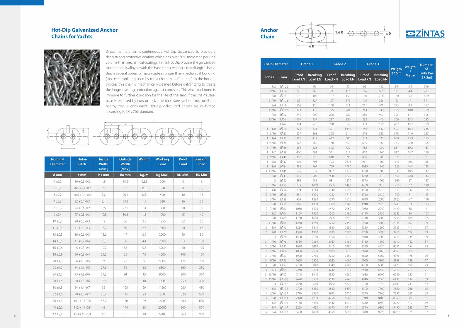
Zintas marine chain is continuously Hot Dip Galvanized to provide a deep strong protective coating which has over 30% more zinc per unit volume than mechanical coatings. In the Hot Dip process the galvanized zinc coating is alloyed with the base steel creating a metallurgical bond that is several orders of magnitude stronger than mechanical bonding (zinc electroplating used by most chain manufacturers). In the hot dip process this chain is mechanically cleaned before galvanizing to create the longest lasting protection against corrosion. This zinc-steel bond is immune to further corrosion for the life of the zinc. If the chain’s steel base is exposed by cuts or nicks the base steel will not rust until the nearby zinc is consumed. Hot-dip galvanized chains are calibrated according to DIN 766 standard.
Nominal Diameter
HatvePitch
Inside Width(Min.)
OutsideWidth (Max.)
Weight WorkingLoad
ProofLoad
BreakingLoad
d mm t mm b1 mm Ba mm Kg/m Kg Max. kN Min. kN Min
4 ±0,2 16 +0,3 -0,2 4,8 13,6 0,32 200 5 8
5 ±0,2 18,5 +0,4 -0,2 6 17 0,5 320 8 12,5
6 ±0,2 18,5 +0,4 -0,2 7,2 20,4 0,8 400 10 16
7 ±0,3 22 +0,4 -0,2 8,4 23,8 1,1 630 16 25
8 ±0,3 24 +0,4 -0,2 9,6 27,2 1,4 800 20 32
9 ±0,4 27 +0,5 -0,3 10,8 30,6 1,8 1000 25 40
10 ±0,4 28 +0,5 -0,3 12 36 2,3 1250 32 50
11 ±0,4 31 +0,5 -0,3 13,2 40 2,7 1600 40 63
13 ±0,5 36 +0,6 -0,3 15,6 47 3,9 2000 50 80
14 ±0,6 41 +0,7 -0,4 16,8 50 4,4 2500 63 100
16 ±0,6 45 +0,8 -0,4 19,2 58 5,8 3200 80 125
18 ±0,9 50 +0,8 -0,4 21,6 65 7,4 4000 100 160
20 ±1,0 56 +1,0 -0,5 24 72 9 5000 125 200
23 ±1,2 64 +1,1 -0,5 27,6 83 12 6300 160 250
26 ±1,3 73 +1,2 -0,6 31,2 94 15 8000 200 320
28 ±1,4 78 +1,3 -0,6 33,6 101 18 10000 250 400
30 ±1,5 84 +1,4 -0,7 36 108 20 11200 280 450
32 ±1,6 90 +1,5 -0,7 38,4 115 23 12500 320 500
36 ±1,8 101 +1,7 -0,8 43,2 130 29 16000 400 630
40 ±2,0 112 +1,9 -0,8 48 144 35 20000 500 800
42 ±2,1 118 +2,0 -1,0 50 151 40 22400 560 900
Chain Diameter Grade 1 Grade 2 Grade 3Weigth27.5 m
Weigth1
Metre
Number of
Links Per(27.5m)inches mm
ProofLoad kN
BreakingLoad kN
ProofLoad kN
BreakingLoad kN
ProofLoad kN
BreakingLoad kN
1/2 12.5 46 66 66 92 92 132 96 3.5 549
9/16 14 58 82 82 116 116 165 121 4,4 491
5/8 16 76 107 107 150 150 216 160 5.8 429
11/16 17.5 89 127 127 179 179 256 193 7 391
3/4 19 105 150 150 211 211 301 223 8.1 357
13/16 20,5 123 175 175 244 244 349 275 10.0 329
7/8 22 140 200 200 280 280 401 305 11.1 305
15/16 24 167 237 237 332 332 476 366 13.3 285
1 26 194 278 278 359 389 556 432 15.7 259
1 1/8 28 225 321 321 I 449 449 642 503 18.3 245
1 3/16 30 257 368 368 514 514 735 578 21.0 225
1 1/4 32 291 417 417 583 583 833 658 23.9 213
1 5/16 34 328 468 468 655 655 937 743 27.0 195
1 7/16 36 366 523 523 732 732 1050 831 30,2 187
1 1/2 38 406 581 581 812 812 1160 927 33.7 179
1 9/16 40 448 640 640 896 896 1280 1020 37.1 171
1 5/8 42 492 703 703 9811 981 1400 1115 40.5 165
1 3/4 44 538 769 769 1080 1080 1540 1220 44.3 153
1 13/16 46 585 837 837 1170 1170 1680 1335 48.5 147
1 7/8 4-8 635 908 908 1270 1270 1810 1455 52.8 143
2 50 886 981 981 1370 1370 1960 1569 57 137
2 1/16 52 739 1060 1060 1480 1480 2110 1710 62 129
2 1/8 54 794 1140 1140 1590 1590 2270 1815 66 125
2 3/16 56 851 1220 1220 1710 1710 2430 1959 71 123
2 5/16 58 909 1290 1290 1810 1810 2600 2120 77 119
2 3/8 50 969 1380 1380 1940 1940 2770 2285 83 113
2 7/16 62 1030 1470 1470 2060 2060 2940 2420 88 111
2 1/2 64 1100 1560 1560 2190 2190 3130 2585 94 107
2 5/8 66 1160 1660 1660 2310 2310 3300 2750 100 105
2 11/16 68 1230 1750 1750 2450 2450 3500 2943 107 99
2 3/4 70 1290 1840 1840 2580 2580 3690 3135 114 97
2 7/8 73 1390 1990 1990 2790 2790 3990 3410 124 93
3 76 1500 2150 2150 3010 3010 4300 3715 135 89
3 1/16 78 1580 2260 2260 3160 3160 4500 3910 142 87
3 3/16 81 1690 2410 2410 3380 3380 4820 4235 154 85
3 5/16 84 1800 2580 2580 3610 3610 5160 4565 166 81
3 7/16 87 1920 2750 2750 3850 3850 5500 4895 178 79
3 9/16 90 2050 2920 2920 4090 4090 5840 5198 189 77
3 5/8 92 2130 3040 3040 4260 4260 6080 5473 199 73
3 3/4 95 2260 3230 3230 4510 4510 6440 5810 211 71
3 13/16 97 2340 3340 3340 4650 4680 6690 6050 220 71
3 15/16 100 2470 3530 3530 4940 4940 7060 6435 234 69
4 102 2560 3660 3660 5120 5120 7320 6685 243 67
4 1/8 105 2700 3850 3850 5390 5390 7700 7320 266 65
4 3/16 107 2790 3980 3980 5570 5570 7960 7895 287 63
4 3/8 111 2970 4250 4250 5940 5940 8480 8360 304 61
4 1/2 114 3110 4440 4440 6230 6230 8890 8720 317 59
4 5/8 117 3260 4650 4650 6510 6510 9300 9490 345 57
4 3/4 120 3400 4850 4850 6810 6810 9720 10313 375 57
Anchor Chain
Hot-Dip Galvanized Anchor Chains for Yachts
30 31

Anchor Shackle Anchor Shackle is used to connect the anchor to the anchor-chain. The shackle require a studless endlink at the chain-side.
Swivel Forerunner The swivel-forerunner is the most common swivel-connection used on ships. The end with a studless endlink fit the anchor-shackle, and the end with a common link for the kenter-shackle.
Kenter Joining Shackle A kenter joining-shackle is used to join two stud link chain elements ending in a common or enlargered link.
Marine Accessories
Swivel Shackle The swivel-shackle is used to minimize the space between the anchor and the chain. One end can connect to crown-shackle or anchor-shank. The other end fit a studless endlink or a common link.
NORBAL BAKLA BÜYÜTÜLMÜŞ BAKLA SON BAKLA
FIRDÖNDÜ
32 33

34 35

DIN 32891 Round Link Chains, Grade 2, Tested and Non-Calibrated
Nominal Diameter
HatvePitch
Inside Width(Min.)
OutsideWidth (Max.)
Weight WorkingLoad
ProofLoad
BreakingLoad
d mm t mm b1 mm Ba mm Kg/m Kg Max. kN Min. kN Min
6 ±0,2 18 ±0,5 8 21,5 0,8 320 6,3 12,5
8 ±0,3 24 ±0,7 10,8 28,8 1,4 630 12,5 25
10 ±0,4 30 ±0,9 13,5 36 2,2 1000 20 40
13 ±0,5 39 ±1,2 17,5 46,8 3,8 1600 32 63
16 ±0,6 48 ±1,4 21,5 57,6 5,7 2500 50 100
18 ±0,9 54 ±1,6 24,3 64,8 7,3 3200 63 125
20 ±1,0 60 ±1,8 27 72 9 4000 80 160
23 ±1,2 69 ±2,1 31 82,8 12 5000 100 200
26 ±1,3 78 ±2,3 35 93,6 15,2 6000 125 250
28 ±1,4 84 ±2,5 37,8 100,8 17,6 8000 160 320
32 ±1,6 96 ±2,9 43,2 115 23 10000 200 400
36 ±1,8 108 ±3,2 48,5 130 29 12500 250 500
40 ±2,0 120 ±3,6 54 144 36 16000 320 630
45 ±2,3 135 ±4,1 61 162 45,5 20000 400 800
Nominal Diameter
DiameterTolerans
Pitch PitchTolerance
InsideWidth
Weight Marking
d mm mm t mm mm Min. mm Kg / m
5 ±0,30 21 ±1,1 9 0,5 B orta
6 ±0,30 24 ±1,2 11 0,73 B orta
7 ±0,40 28 ±1,4 12 0,99 B orta
8 ±0,40 32 ±1,6 14 1,3 B orta
10 ±0,50 40 ±2 18 2,00 B orta
13 ±0,70 52 ±2,6 23 3,40 B orta
Nominal Diameter
DiameterTolerans
Pitch PitchTolerance
InsideWidth
Weight Marking
d mm mm t mm mm Min. mm Kg / m
5 ±0,30 18,5 ±0,9 7 0,51 C kısa
6 ±0,30 18,5 ±0,9 8 0,78 C kısa
7 ±0,40 22 ±1,1 9,5 1,1 C kısa
8 ±0,40 24 ±1,2 11 1,4 C kısa
10 ±0,50 28 ±1,4 14 2,3 C kısa
13 ±0,70 36 ±1,8 18 3,9 C kısa
16 ±0,80 45 ±2,3 22 5,8 C kısa
DIN 5685 Round Steel Link Chains Non-Proof Loaded
36 37

NominalDiameter &Tolerance
Pitch &Tolerans
InsideWidth(Min.)
Weight Materials (DIN 17115)
ProofLoad
Breaking Load
d mm t mm b1 mm Kg/m kN Min. kN Min
16 ±0,6 80 ±1,5 22,4 +3 4,7 15Mn3Al 60 180
18 ±0,9 90 ±1,5 25 +3 6 21Mn5 100 250
Nominal DiameterTolerance
Pitch & Tolerance
InsideLenght(Min.)
OutsideLenght (Max.)
Weight Quality Working Load Working Load ProofLoad
BreakingLoad
d mm t mm b1 mm b2 mm Kg/m Grade Kg Max. Kg Max. kN Min. kN Min
4 ±0,212 +0,15
-0,15 13,7 0,35
5 250 320 6,3 12,5
6 320 400 8 16
5 ±0,215 +0,2
-0,16 16,9 0,54
5 400 500 10 20
6 500 630 12,5 25
6 ±0,218 +0,25
-0,17,2 20,2 0,8
5 600 750 15 30
6 750 900 18 37,5
7 ±0,321 +0,3
-0,158,4 23,6 1,1
5 800 1000 20 40
6 1000 1250 25 50
8 ±0,324 +0,3
-0,159,6 27 1,4
5 1000 1250 25 50
6 1250 1600 32 63
9 ±0,427 +0,35
-0,210,8 30,4 1,8
5 1250 1600 32 63
6 1600 2000 40 80
10 ±0,428 +0,35
-0,212 34 2,2
5 1600 2000 40 80
6 2000 2500 50 100
11 ±0,431 +0,4
-0,213,2 37,4 2,7
5 2000 2500 50 100
6 2500 3000 60 125
13 ±0,536 +0,45
-0,2515,6 44,2 3,8
5 2650 3350 67 132
6 3200 4250 85 170
14 ±0,641 +0,5
-0,316,8 47,6 4,4
5 3200 4000 80 160
6 4000 5000 100 200
16 ±0,645+0,6
-0,319,2 54,4 5,7
5 4000 5000 100 200
6 5000 6300 125 250
18 ±0,950 +0,65
-0,321,6 61,2 7,3
5 5000 6300 125 250
6 6300 8000 160 320
DIN 20637 Monorails for Minining – Tested Round Steel Chains for Suspensions – Long Link
DIN 5685 Round Steel Link Chains Non-Proof Loaded
DIN 5684 Round Steel Link Chains for Lifting Purposes, Grade 5-6, Calibrated and Tested
Nominal Diameter
DiameterTolerans
Pitch PitchTolerance
InsideWidth
Weight Marking
d mm mm t mm mm Min. mm Kg / m
5 ±0,30 35 ±1,8 9 0,42 A uzun
6 ±0,30 42 ±2,1 11 0,61 A uzun
7 ±0,40 49 ±2,5 12 0,82 A uzun
8 ±0,40 52 ±2,6 14 1,1 A uzun
10 ±0,50 65 ±3,3 18 1,7 A uzun
13 ±0,70 82 ±4,1 23 2,9 A uzun
38 39

Nominal DiameterTolerance
Pitch & Tolerance
InsideLenght(Min.)
OutsideLenght (Max.)
Weigth QualityWorking
Load
ProofLoad
BreakingLoad
d mm t mm b1 mm Ba mm Kg/m Grade Kg Max. kN Min. kN Min
4 ±0,212 +0,15
-0,15 13,7 0,35 8 500 12,5 20
5 ±0,215 +0,2
-0,16 16,9 0,54 8 750 20 32
6 ±0,218 +0,25
-0,17,2 20,2 0,8 8 1120 28 45
7 ±0,321 +0,3
-0,158,4 23,6 1,1 8 1500 40 60
8 ±0,324 +0,3
-0,159,6 27 1,4 8 2000 50 80
9 ±0,427 +0,35
-0,210,8 30,4 1,8 8 2500 63 100
10 ±0,428 +0,35
-0,212 34 2,2 8 3200 80 125
11 ±0,431 +0,4
-0,213,2 37,4 2,7 8 3750 95 150
13 ±0,536 +0,45
-0,2515,6 44,2 3,8 8 5300 132 212
14 ±0,641 +0,5
-0,316,8 47,6 4,4 8 6000 150 250
16 ±0,645+0,6
-0,319,2 54,4 5,7 8 8000 200 315
18 ±0,950 +0,65
-0,321,6 61,2 7,3 8 10000 250 400
DIN 5684 Round Steel Link Chains for Lifting Purposes, Grade 5-6, Calibrated and Tested
DIN 5687 Round Link Chains, Grade 5, Tested
Nominal DiameterTolerance
Pitch & Tolerance
InsideLenght(Min.)
OutsideLenght (Max.)
WeigthWorking
Load ProofLoad
BreakingLoad
d mm t mm b1 mm b2 mm Kg/m Kg kN kN
6 ±0,2 18 ±0,5 8 21,6 0,8 750 19 30
8 ±0,3 24 ±0,7 10,8 28,8 1,4 1250 32 50
10 ±0,4 30 ±0,9 13,5 36 2,2 2000 50 80
13 ±0,5 39 ±1,2 17,5 46,8 3,8 3200 80 125
16 ±0,6 48 ±1,4 21,5 57,6 5,7 5000 125 200
18 ±0,9 54 ±1,6 24,3 64,8 7,3 6300 160 250
20 ±1,0 60 ±1,8 27 72 9 8000 200 320
22 ±1,1 66 ±2,0 29,5 79,2 10,9 10000 250 400
26 ±1,3 78 ±2,3 35 93,6 15,2 12500 320 500
28 ±1,4 84 ±2,5 37,8 100,8 17,6 16000 400 630
32 ±1,6 96 ±2,9 43,2 115 23 20000 500 800
36 ±1,8 108 ±3,2 48,5 130 29 25000 630 1000
40 ±2,0 120 ±3,6 54 144 36 32000 800 1250
45 ±2,3 135 ±4,1 61 162 45,5 40000 1000 1600
40 41

Nominal Diameter &Tolerance
WeldingDiameter
(Max.)
Pitch &Tolerans
InsideWidth (Min.)
OutsideWidth (Max.)
Weight WorkingLoadLimit
ProofLoad (Min.)
BreakingLoad (Min.)
dn ds t b1 b2 Kg/m Kg kN kN
4 ±0,16 4,4 12 ±0,4 5,2 14,8 0,35 500 12,6 20,1
5 ±0,2 5,5 15 ±0,4 6,5 18,5 0,5 800 19,6 31,4
6 ±0,24 6,6 18 ±0,5 7,8 22,2 0,8 1120 28,3 45,2
7 ±0,28 7,7 21 ±0,6 9,1 25,9 1,1 1500 38,5 61,6
8 ±0,32 8,8 24 ±0,7 10,4 29,6 1,4 2000 50,3 80,4
10 ±0,4 11 30 ±0,9 13 37 2,2 3150 78,5 126
13 ±0,52 14,3 39 ±1,2 16,9 48,1 3,8 5300 133 212
16 ±0,64 17,6 48 ±1,4 20,8 59,2 5,7 8000 201 322
18 ±0,9 19,8 54 ±1,6 23,4 66,6 7,3 10000 254 407
19 ±1,0 20,9 57 ±1,7 24,7 70,3 8,1 11200 284 454
20 ±1,0 22 60 ±1,8 26 74 9 12500 314 503
22 ±1,1 24,2 66 ±2,0 28,6 81,4 10,9 15000 380 608
23 ±1,2 25,3 69 ±2,1 29,9 85,1 12 16000 415 665
25 ±1,3 27,5 75 ±2,2 32,5 92,5 14,1 20000 419 785
26 ±1,3 28,6 78 ±2,3 33,8 96,2 15,2 21200 531 849
28 ±1,4 30,8 84 ±2,5 36,4 104 17,6 25000 616 985
32 ±1,6 35,2 96 ±2,9 41,6 118 23 31500 804 1290
36 ±1,8 39,6 108 ±3,0 46,8 133 29 40000 1020 1630
40 ±2,0 44 120 ±4,0 52 148 36 50000 1260 2010
45 ±2,3 49,5 135 ±4,0 58,5 167 45,5 63000 1590 2540
EN 818-2-8 Sling ChainsGrade 80
EN 818-2 Sling ChainsGrade 100
Nominal Diameter
&Tolerance
WeldingDiameter
(Max.)
Pitch &Tolerans
InsideWidth (Min.)
OutsideWidth (Max.)
Weight WorkingLoadLimit
ProofLoad (Min.)
BreakingLoad (Min.)
dn mm ds mm t mm b1 mm b2 mm Kg/m Kg kN kN
6 ±0,24 6,6 18 ±0,5 7,8 22,2 0,8 1400 35,3 56,5
7 ±0,28 7,7 21 ±0,6 9,1 25,9 1,1 1900 48,1 77
8 ±0,32 8,8 24 ±0,7 10,4 29,6 1,4 2500 62,8 101
10 ±0,4 11 30 ±0,9 13 37 2,2 4000 98,2 157
13 ±0,52 14,3 39 ±1,2 16,9 48,1 3,8 6700 166 265
16 ±0,64 17,6 48 ±1,4 20,8 59,2 5,7 10000 251 402
18 ±0,9 19,8 54 ±1,6 23,4 66,6 7,3 12500 318 509
19 ±1,0 20,9 57 ±1,7 24,7 70,3 8,1 14000 354 567
20 ±1,0 22 60 ±1,8 26 74 9 16000 393 628
22 ±1,1 24,2 66 ±2,0 28,6 81,4 10,9 19000 475 760
23 ±1,2 25,3 69 ±2,1 29,9 85,1 12 20000 519 831
26 ±1,3 28,6 78 ±2,3 33,8 96,2 15,2 26500 664 1060
42 43

These chains are short link lifting chains of medium tolerance for used in chain
slings and for general lifting purposes.
T - Hardened and tempered
DAT - Surface hardened
DT - Surface hardened, with higher surface hardness and higher hardening depth than DAT
NominalDiameter
Pitch Tolerance InsideWidth b1
OutsideWidth b2
Weight Working Load kg
ProofLoad
Breaking Load
mm mm mm mm mm Kg/m T DAT DT kN kN
4± 0,2 12 0,25 4,8 13,6 0,35 500 400 250 12,6 20,1
5± 0,2 15 0,3 6 17 0,54 800 630 400 19,6 31,4
6± 0,2 18 0,35 7,2 20,4 0,8 1.100 900 560 28,3 45,2
7± 0,3 21 0,4 8,4 23,8 1,1 1.500 1.200 750 38,5 61,6
8± 0,3 24 0,5 9,6 27,2 1,4 2.000 1.600 1.000 50,3 80,4
9± 0,4 27 0,5 10,8 30,6 1,8 2.500 2.000 1.250 63,6 102
10± 0,4 30 0,6 12 34 2,2 3.200 2.500 1.600 78,5 126
11± 0,4 31 0,6 13,2 37,4 2,7 3.800 3.000 1.900 95 152
12± 0,5 36 0,7 14,4 40,8 3,1 4.500 3.600 2.200 113 181
13± 0,5 39 0,8 15,6 44,2 3,7 5.300 4.200 2.600 133 212
14± 0,6 42 0,8 16,8 47,6 4,3 6.000 5.000 3.000 154 246
16± 0,6 48 0,9 19,2 54,4 5,6 8.000 6.300 4.000 201 322
18± 0,9 54 1 21,6 61,2 7 10.000 8.000 5.000 254 407
20± 1,0 60 1,2 24 68 8,7 12.500 10.000 6.300 314 503
22± 1,1 66 1,3 26,4 74,8 10,5 15.000 12.500 7.500 380 608
EN 818-7 Hoist ChainsGrade 80
Chain Accessories Master Link
Chain Connecting Link
Chain Ø (mm) Dmm
Lmm
Imm
Weightkg
Working LoadLimit (TON)
1'li 2'li
6 6 13 110 60 0,35 1,6
8 6 16 110 60 0,53 2
10 8 18 135 75 0,80 3,2
13 10 22 160 90 1,50 5
16 13 26 180 100 2,30 8
18 16 32 200 110 3,90 11,2
20 18 36 260 140 6,35 14
22 20 40 300 160 9,00 18
26-28 22 45 340 180 12,80 25
32 26-28 51 350 190 17,20 32
36 32 57 400 200 24,20 40
40 36 63 430 220 32,00 50
45 40 72 460 250 46,00 63
- 45 80 500 270 62,00 80
Chain Ø (mm)
A mm LU mm C mm D mm O mmWeight
KgWorking Load
Limit TON
6 7 43 16 18 14 0,07 1,12
7 8 49 18 20 17 0,10 1,50
8 9 70 26 25 21 0,25 2,00
10 12 77 30 27 23 0,35 3,15
13 17 83 31 30 28 0,68 5,30
16 20 101 38 39 33 1,10 8,00
20 23 117 45 46 41 1,65 12,50
22 27 133 51 55 45 2,90 15,00
26 30 146 52 67 56 4,16 21,20
32 37 183 69 79 67 7,19 31,50
44 45

U Type Chain Shackle Omega Type Chain Shackle
A mm B mm C mm D mm E mm Weight KgWorking L.
LimitTON
6 8 12 22 18 0,05 0,50
8 10 14 26 21 0,06 0,75
10 11 16 32 25 0,11 1,00
11 13 18 37 27 0,18 1,50
13 16 21 41 30 0,34 2,00
16 19 27 51 40 0,67 3,25
19 22 32 60 48 1,14 4,75
22 25 37 71 54 1,74 6,50
25 29 43 81 60 2,52 8,50
28 32 46 90 67 3,45 9,50
32 35 52 100 76 4,90 12,00
35 38 57 111 84 6,47 13,50
38 41 60 122 92 8,63 17,00
45 51 73 146 110 14,20 25,00
50 57 83 171 127 21,20 35,00
65 70 105 203 152 38,50 55,00
76 82 127 216 165 56,50 85,00
89 95 133 266 203 93,00 120,00
A mm B mm C mm D mm E mm F mm Weight KgWorking L.
LimitTON
5 6 10 22 14 18 0,02 0,33
6 8 12 29 18 20 0,05 0,50
8 10 14 31 21 21 0,08 0,75
10 11 16 37 25 26 0,14 1,00
11 13 18 43 27 29 0,20 1,50
13 16 21 48 30 33 0,36 2,00
16 19 27 60 40 43 0,73 3,25
19 22 32 71 48 51 1,23 4,75
22 25 37 84 54 58 1,79 6,50
25 29 43 95 60 68 3,75 8,50
28 32 46 108 67 74 3,75 9,50
32 35 52 119 76 83 5,31 12,00
35 38 57 132 84 89 7,18 13,50
38 41 60 146 92 98 9,43 17,00
45 51 73 178 110 127 15,40 25,00
50 57 83 197 127 146 23,50 35,00
65 70 105 267 152 184 46,10 55,00
76 82 127 330 165 170 81,00 85,00
89 95 133 371 203 200 120,00 120,00
100 108 140 368 229 240 153,00 150,00
46 47

Quality Cerfiticates
IQNet Quality Certificate Rina ISO
TS 663 TSE 11987 TS 1363
48

www.zintas.come-mail: [email protected]
www.kosgeb.gov.tr
GARAJ TASARIMŞehit Ersan Cad. 30-1 Çankaya ANKARAT: +90 312 467 15 37 F: +90.312 467 16 92www.garajtasarim.com
Printing Date : 31.07.2015
Zintaş Kastamonu Chain Industry & Trade Co.
Factory / Sale OfficeAnkara Yolu 5. km. 37130 Kastamonu / TRT : +90.366 214 23 37 - 214 99 01F : +90.212 381 62 32
Office Atatürk Bulvarı Ünlü İş Merkezi No: 23/46 Unkapanı - İstanbul / TRT: +90.212 531 28 03 F: +90.212 381 62 32