product data sheet/ installation instructions kuka
TRANSCRIPT
Product Data Sheet / Installation Instructions KUKA Connectivity Box
12.10.2018 KUKA Connectivity Box Page 1 of 8
Product Data Sheet/ Installation Instructions
KUKA Connectivity Box
Table of Contents
1 Description of Product 2
2 Technical Data of the KUKA Connectivity Box 2
2.1 Product Data 2
2.2 Optional Accessories 2
2.3 Dimensions of the KUKA Connectivity Box 3
2.4 General Technical Data 3
2.4.1 Housing 3
2.4.2 Hardware Equipment 3
2.4.3 Electrical Data 4
2.4.4 Permissible Ambient Conditions 4
2.4.5 Standards, Specifications 4
3 Installation Instructions, Description of Hardware Interfaces 4
3.1 Overview and Arrangement of Interfaces 4
3.1.1 Description of Interfaces 5
3.1.2 Pin Assignment Voltage Supply XP1 5
3.1.3 Components on Front (under Front Panel) 6
3.1.3.1 Micro-USB Interface 6
3.1.3.2 Micro SD Memory Card Slot 6
4 Commissioning (Integration in Production Line and Machines) 7
4.1 Customer Requirements 7
4.1.1 Assembly of the KUKA Connectivity Box 7
4.1.2 Commissioning 7
4.2 Operation and Fault Diagnostics 7
4.2.1 Defined Blinking Frequency of the Status LEDs 8
4.2.2 Error Codes for Status LEDs 8
4.3 KUKA Contact, Support and Service 8
Product Data Sheet / Installation Instructions KUKA Connectivity Box
12.10.2018 KUKA Connectivity Box Page 2 of 8
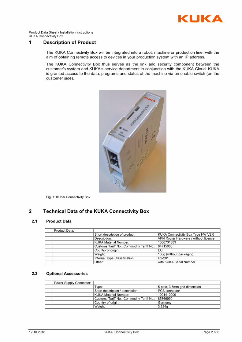
1 Description of Product
The KUKA Connectivity Box will be integrated into a robot, machine or production line, with the aim of obtaining remote access to devices in your production system with an IP address.
The KUKA Connectivity Box thus serves as the link and security component between the customer's system and KUKA’s service department in conjunction with the KUKA Cloud. KUKA is granted access to the data, programs and status of the machine via an enable switch (on the customer side).
Fig. 1: KUKA Connectivity Box
2 Technical Data of the KUKA Connectivity Box
2.1 Product Data
Product Data:
Short description of product: KUKA Connectivity Box Type HW V2.0
Description: VPN Router Hardware / without licence
KUKA Material Number: 1000731883
Customs Tariff No., Commodity Tariff No.: 84715000
Country of origin: EU
Weight: 130g (without packaging)
Internal Type Classification: C2-201
Other: with KUKA Serial Number
2.2 Optional Accessories
Power Supply Connector:
Type: 5-pole, 3.5mm grid dimension
Short description / description: PCB connector
KUKA Material Number: 1001410009
Customs Tariff No., Commodity Tariff No.: 85366990
Country of origin: Germany
Weight: 3.324g
Product Data Sheet / Installation Instructions KUKA Connectivity Box
12.10.2018 KUKA Connectivity Box Page 3 of 8
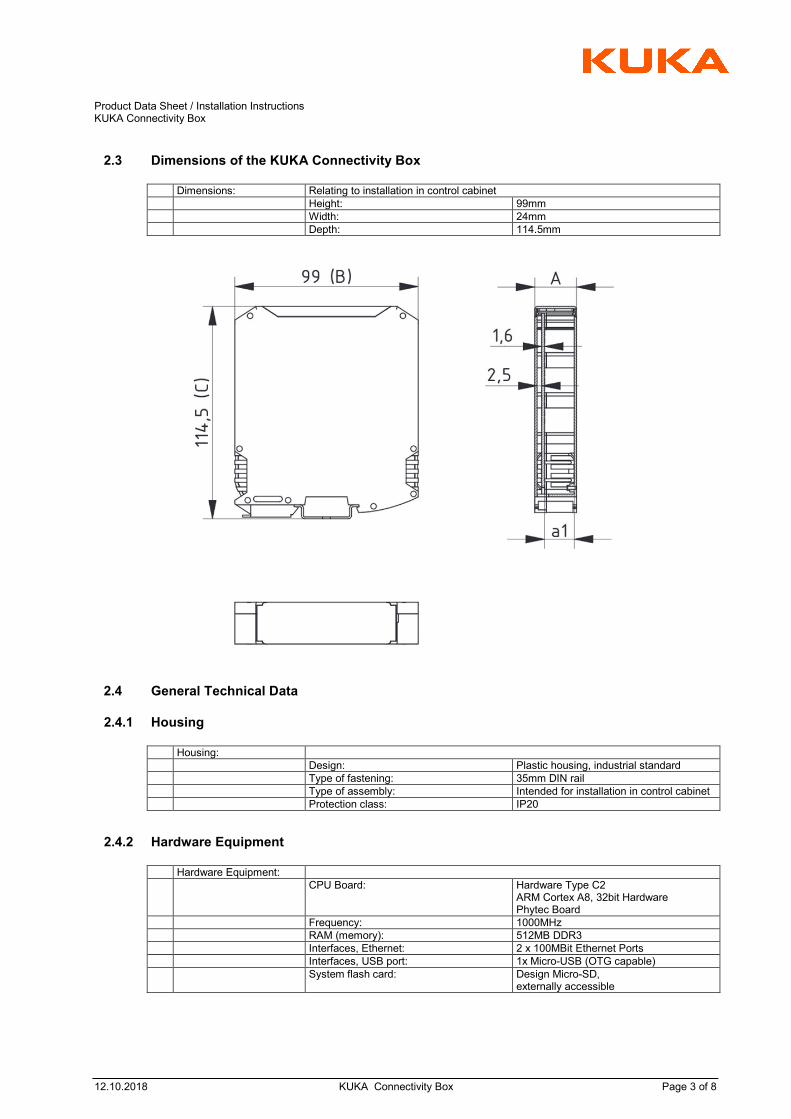
2.3 Dimensions of the KUKA Connectivity Box
Dimensions: Relating to installation in control cabinet
Height: 99mm
Width: 24mm
Depth: 114.5mm
2.4 General Technical Data
2.4.1 Housing
Housing:
Design: Plastic housing, industrial standard
Type of fastening: 35mm DIN rail
Type of assembly: Intended for installation in control cabinet
Protection class: IP20
2.4.2 Hardware Equipment
Hardware Equipment:
CPU Board: Hardware Type C2 ARM Cortex A8, 32bit Hardware Phytec Board
Frequency: 1000MHz
RAM (memory): 512MB DDR3
Interfaces, Ethernet: 2 x 100MBit Ethernet Ports
Interfaces, USB port: 1x Micro-USB (OTG capable)
System flash card: Design Micro-SD, externally accessible
Product Data Sheet / Installation Instructions KUKA Connectivity Box
12.10.2018 KUKA Connectivity Box Page 4 of 8
2.4.3 Electrical Data
Electrical Data:
Voltage supply: DC, external
Voltage range: 24V(nominal) (19.2V minimal – 28.8V maximal)
Power consumption: <10W, depends on operating status
Current consumption: max. 0.45A
max. fuse protection/pre-fuse protection: 2A
2.4.4 Permissible Ambient Conditions
Permissible Ambient Conditions:
Protection class: IP20
max. ambient temperature during operation:
0°C … +40°C
max. ambient temperature during transport and storage:
-40°C … +40°C
Permissible humidity: 10% … 95% (no condensation)
Permissible air pressure: 53 kPa ... 108 kPa (5000 m üNN)
Place of installation: Control cabinet, terminal box
Installation position : arbitrary
Required spacing: Stacks and rows possible, min. 20mm distance from e.g. cable duct
2.4.5 Standards, Specifications
Standards, specifications,:
Certification: CE mark
3 Installation Instructions, Description of Hardware Interfaces
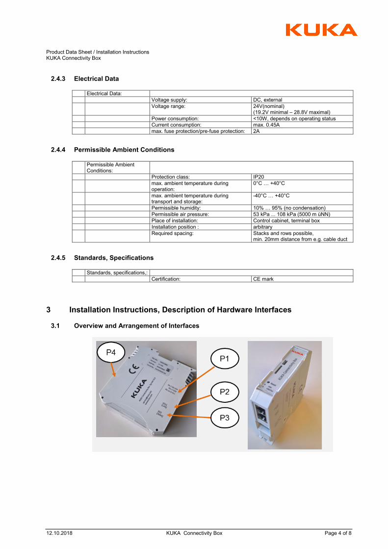
3.1 Overview and Arrangement of Interfaces

Product Data Sheet / Installation Instructions KUKA Connectivity Box
12.10.2018 KUKA Connectivity Box Page 5 of 8
3.1.1 Description of Interfaces
Description of Interfaces:
P1 XP1 Voltage supply
P2 XD11 (LAN) Connection to network (internal, to production line) (RJ45)
P3 XD2 (WAN) Connection to network (external, “Internet”) (RJ45)
P4 Not assigned, not used
3.1.2 Pin Assignment Voltage Supply XP1
P1 XP1, voltage supply
Pin 1 Vin, 24V DC +
Pin 2 GND (0V)
Pin 3 N.C.
Pin 4 N.C.
Pin 5 N.C.
Product Data Sheet / Installation Instructions KUKA Connectivity Box
12.10.2018 KUKA Connectivity Box Page 6 of 8
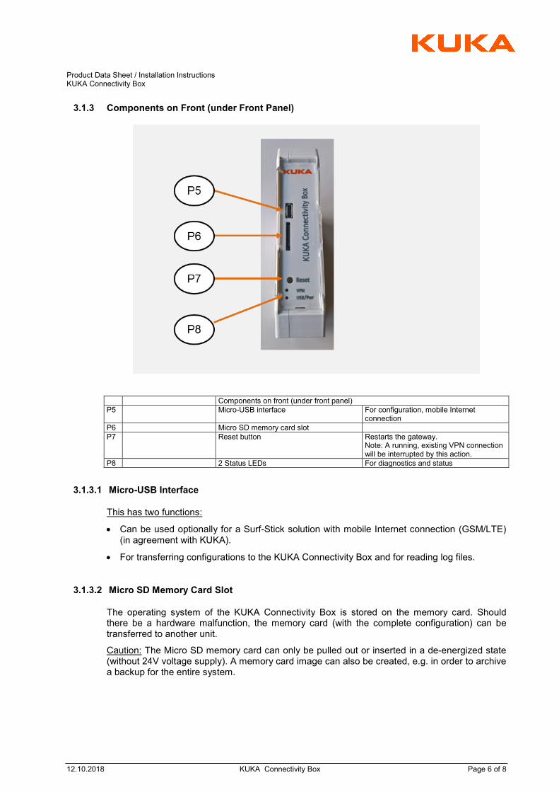
3.1.3 Components on Front (under Front Panel)
Components on front (under front panel)
P5 Micro-USB interface For configuration, mobile Internet connection
P6 Micro SD memory card slot
P7 Reset button
Restarts the gateway. Note: A running, existing VPN connection will be interrupted by this action.
P8 2 Status LEDs For diagnostics and status
3.1.3.1 Micro-USB Interface
This has two functions:
Can be used optionally for a Surf-Stick solution with mobile Internet connection (GSM/LTE) (in agreement with KUKA).
For transferring configurations to the KUKA Connectivity Box and for reading log files.
3.1.3.2 Micro SD Memory Card Slot
The operating system of the KUKA Connectivity Box is stored on the memory card. Should there be a hardware malfunction, the memory card (with the complete configuration) can be transferred to another unit.
Caution: The Micro SD memory card can only be pulled out or inserted in a de-energized state (without 24V voltage supply). A memory card image can also be created, e.g. in order to archive a backup for the entire system.

Product Data Sheet / Installation Instructions KUKA Connectivity Box
12.10.2018 KUKA Connectivity Box Page 7 of 8
4 Commissioning (Integration in Production Line and Machines)
4.1 Customer Requirements
The following preconditions are necessary for commissioning and operation:
Assembly and integration into the local network is carried out by the customer or as a part of a customer project.
Internet access will be provided by the customer. This can be done via Ethernet or mobile network.
4.1.1 Assembly of the KUKA Connectivity Box
Assembly of the KUKA Connectivity Box on a DIN rail in the control cabinet
Installation of 24V voltage supply
Establishment of the internal and external network connection
Commissioning of the software takes place in coordination and cooperation with KUKA’s Service Dept.
4.1.2 Commissioning
Commissioning of the software takes place in coordination and cooperation with KUKA’s Service Dept.
The appropriate technical agreements, e.g. IP addresses, are to be made in advance
Corresponding licences and software configurations will be provided by the Service Dept.
As an option, an external user access can be set up in consultation with KUKA’s Service Dept.
4.2 Operation and Fault Diagnostics
On the front panel the KUKA Connectivity Box has the following display and operating elements:
Status LED red (VPN) used for the (VPN) connection status
Status LED red (USB/Pwr) Power, boot status, USB and update status
Reset Button Restarts the gateway. Note: By doing this, a running, existing VPN connection will be interrupted.

Product Data Sheet / Installation Instructions KUKA Connectivity Box
12.10.2018 KUKA Connectivity Box Page 8 of 8
4.2.1 Defined Blinking Frequency of the Status LEDs
Defined blinking frequency of the status LEDs
Blink 1 Heartbeat 100ms on; 100ms off
Blink 2 Heartbeat 400ms on; 400ms off
Blink 3 Heartbeat 1000ms on; 1000ms off
Blink 4 Heartbeat 3000ms on; 400ms off
Blink 5 Heartbeat 3000ms on; 3000ms off
ON Steady light
OFF LED is off
4.2.2 Error Codes for Status LEDs
LED red (USB/Pwr) LED red (VPN) BIOS Code Error Messages
1 OFF OFF Reset Status / Loading the operating system
2 Blink 2 OFF Boot loader initialisation
3 Blink 2 ON General hardware fault
4 Blink 2 Blink 1 Micro SD memory card missing
LED red (USB/Pwr) LED red (VPN) Operating System Error Messages
5 Heartbeat OFF Recovery system is active
6 Heartbeat Blink 1 Error in recovery system
7 Heartbeat ON Initial check went well / Base system active
8 Blink 3 OFF Loading of operating system
9 Blink 3 Blink 1 Error during loading of operating system
10 ON OFF KUKA Connectivity Box in operation, no tunnel active
11 Blink 4 OFF A USB flash drive is inserted and can be used
12 Blink 5 OFF An update is in progress
13 Blink 1 OFF A error has occurred during the update
14 OFF ON VPN Tunnel CRSM Server (at KUKA) is established
15 OFF Blink 4 VPN Tunnel connection set up
16 OFF Blink 3 Internet connection set up
17 OFF Blink 1 VPN Tunnel is set up but problems with the network identified
4.3 KUKA Contact, Support and Service
Further information and support can be obtained from:
KUKA Deutschland GmbH Zugspitzstrasse 140
86165 Augsburg E-Mail: [email protected]
Telefon: +49 821 797 1926