product manual for tractor - northern tool - equipment · pdf filemade in china . user notices...
TRANSCRIPT

NorTrac 35XT Tractor
Owner’s Manual
Sold By
Northern Tool & Equipment, Inc.
P.O. Box 1299
Burnsville, MN 55337
Tel.: 1-800-222-5381
www.northerntool.com

User Notices
NorTrac 35XT Tractor
Product Identification Data Sheet
Product Part Number
Product Model
Machine Serial Number
Chassis Serial Number
Engine Model
Engine Serial Number
Date of Purchase
Where Purchased/Contact Information
Owner Name
Complete this form carefully at purchase.
All serial numbers in this form should be recorded completely (including letters).
Distributed by
Northern Tool & Equipment Co., Inc. Burnsville, MN 55306-6936
Made in China

User Notices
Thank You
Thank you for purchasing a NorTrac tractor from Northern Tool & Equipment Company. We value you as a
customer and wish you many years of safe and satisfied use of your tractor.
Using Your Owner’s Manual
This Owner’s Manual is an important part of your tractor and should remain with the tractor if you sell it.
Failure to follow the tractor break-in procedure will void the warranty on the tractor.
Read this Owner’s Manual to help you and others avoid personal injury or damage to the tractor. This manual
provides information on the safest and most effective use of the tractor. It will help you and others you might
train to operate the tractor safely and correctly.
If you use the tractor with an implement or other attachment, use the safety and operating instructions in the
owner’s manual for that implement or attachment along with this Owner’s Manual so you can operate the
implement safely and correctly with the tractor.
While the tractor shown in this manual may differ slightly from your tractor model, the instructions in this manual
will apply to your tractor unless otherwise stated.
Disclaimer
The 35XT tractor and its components may be changed by the manufacturer at any time without notice and may not
correspond to the contents of this Owner’s Manual.

Overview
This manual describes safety precautions as well as running-in, proper usage, technical maintenance, adjustment,
faults and troubleshooting methods for various parts of the NorTrac XT tractors. The manual gives an in-depth
look and should be used as a reference tool for owners and maintenance personnel.
In this manual, the safety alert symbol prompts important safety information. When this
symbol is seen, you should be alert to possible injuries or affects to the service performance of the machine.
WARNING: Alerts you to safety hazards that could result in serious injury or even death.
NOTICE: Alerts you to actions that could result in minor injuries or could damage the tractor or
its implements and thus result in possible safety hazards.
IMPORTANT ISSUES: Issues that may result in damage to the tractor, related machinery and/or the
environment.
NOTE: Provides additional information on a given topic.
Please read the messages that follow the symbol carefully and make other operators aware of any potentially
hazardous situations. This manual is an integral part of the product and should be kept with the tractor. Please
keep it in a safe, dry place. If you encounter any sections that you do not understand while going over the
manual, please call 1-800-222-5381 for assistance.
Only those familiar with this manual and the characteristics of this machine should be allowed to operate, service
and maintain the tractor. In addition, government regulations specify that no one under the age of 16 may be
employed to operate power machinery. (Refer to U.S. Department of Labor, Employment Standards
Administration, Wage and Hour Division, Child Labor Bulletin #102.)
In employment conditions, current OSHA regulations state in part: “At the time of initial assignment and at least
annually thereafter, the employer shall instruct every employee in the safe operation and servicing of all
equipment with which the employee is, or will be, involved.”
Observe the accident prevention rules as well as other safety regulations and local traffic rules at all times.
The manufacturer is not liable for any damage to the machine or personal injury resulting from any unauthorized
refitting of this machine or use of the tractor for tasks that are outside the scope of the tractors usage guidelines
.

Table of Contents
Table of Contents
1. Safety Precautions ................................................................................................................................... 1
1.1 Safety rules and notices of use................................................................................................................. 1
1.2 Safety warning symbols........................................................................................................................... 6
1.3 Preventing farm machine hazards.......................................................................................................... 10
2. Operating Instructions .......................................................................................................................... 14
2.1 Product description ................................................................................................................................ 15
2.2 Tractor operating controls and instrumentation ..................................................................................... 15
2.3 Starting the engine ................................................................................................................................. 21
2.4 Driving the tractor ................................................................................................................................. 23
2.5 Steering the tractor................................................................................................................................. 24
2.6 Gear shifting .......................................................................................................................................... 24
2.7 Differential lock operation..................................................................................................................... 25
2.8 Front drive axle use ............................................................................................................................... 25
2.9 Tractor braking ...................................................................................................................................... 26
2.10 Stopping the tractor and engine shutoff procedure .............................................................................. 27
2.11 Tire usage and assembly/disassembly.................................................................................................. 27
2.12 Counterweight ..................................................................................................................................... 28
2.13 Driver’s seat adjustment ...................................................................................................................... 29
2.14 Hydraulic suspension, PTO, and electrical system operation.............................................................. 29
2.15 Tractor break-in ................................................................................................................................... 37
2.16 Tractor faults and troubleshooting ..................................................................................................... 42
3. Accessories and Consumables............................................................................................................... 51
3.1 Accessories ............................................................................................................................................ 51
3.2 List of consumables ............................................................................................................................... 51
4. Maintenance Instructions ..................................................................................................................... 52
4.1 Technical maintenance procedures ........................................................................................................ 52
4.2 Clutch adjustment ................................................................................................................................ 56
4.3 Brake adjustment ................................................................................................................................... 58
4.4 Differential lock adjustment .................................................................................................................. 59
4.5 Steering system adjustment ................................................................................................................... 60
4.6 Front drive axle adjustment ................................................................................................................... 61
4.7 Hydraulic lifting mechanism adjustment............................................................................................... 62
4.8 Battery maintenance .............................................................................................................................. 63

Table of Contents
4.9 Air filter use and maintenance ............................................................................................................... 63
4.10 Fan belt tensioning adjustment ............................................................................................................ 64
4.11 Engine oil maintenance and changing the oil ...................................................................................... 65
4.12 Fuel filter maintenance ........................................................................................................................ 66
4.13 Engine oil filter maintenance............................................................................................................... 66
4.14 Lifter hydraulic oil filter maintenance ................................................................................................. 66
4.15 Front drive oil level maintenance ........................................................................................................ 67
4.16 Transmission oil level maintenance..................................................................................................... 67
4.17 Lifter assembly maintenance ............................................................................................................... 68
4.18 Fuel tank maintenance ......................................................................................................................... 68
4.19 Tire inflation ........................................................................................................................................ 68
4.20 Engine cooling system maintenance.................................................................................................... 69
4.21 Bleeding the fuel system...................................................................................................................... 69
5. Storage .................................................................................................................................................... 70
5.1 Causes of damage .................................................................................................................................. 70
5.2 Tractor storage ....................................................................................................................................... 70
5.3 Tractor storage maintenance .................................................................................................................. 71
5.4 Removing tractor from storage.............................................................................................................. 71
6. Transportation ....................................................................................................................................... 72
7. Technical Specifications ........................................................................................................................ 73
7.1 Main technical specifications for 35XT series tractors.......................................................................... 73
8. Disassembly and Disposal ..................................................................................................................... 78
9. Limited Warranty ................................................................................................................................ 79
10. Appendices............................................................................................................................................ 81
10.1 Tractors fuel, oils and solutions ........................................................................................................... 81
10.2 Main bolts, screws and nuts tightening torque .................................................................................... 82
10.3 Tractor bearings ................................................................................................................................... 83
10.4 Seals on the tractor chassis .................................................................................................................. 86

Safety Precautions
1
1. Safety Precautions 1.1 Safety Rules and Notices of Use
Reading Prior to Use
1 The instructions for use, maintenance, and the safety warning identifiers
should be fully read and understood.
2. The correct usage and operating method should be observed.
3. Local traffic rules and safety regulations must be observed at all times.
Fig. 1-1 Reading prior to use
A Qualified Operator
1. When operating the machine, the driver must use sound judgment.
2. Never operate the tractor if you have been drinking or are tired.
3. The driver should read and understand this operator’s manual.
4. Drive slowly at first in order to test your skill level.
Fig. 1-2 A qualified operator
Clothing
During the operation, the driver should avoid loose fitting clothing. Baggy
and bulky clothes are not recommended.
Fig.1-3 Driver’s clothes
Fuel Usage
1. Diesel fuel is a combustible substance. Keep all fuel away from open flames.
2. The engine should be shut down prior to refueling. 3. Smoking is strictly prohibited when the fuel system is being
refueled and overhauled. 4. Use a clean rag to wipe off any fuel or machine oil overflow. 5. The requirements set out in the Appendix must be strictly complied
with for fuel and lubricating oil quality assurance..
Fig.1-4 Use of fuel

Safety Precautions
2
Waste Oil Disposal 1. Used machine oil is a hazardous waste. Dispose of it properly. 2. The used acid from the battery is also a hazardous waste. Dispose of it properly.
Fig.1-5 Waste oil disposal
Hydraulic Line Leaks Do not use your hand to check for leaks in the high-pressure hydraulic oil lines. You may use a piece of cardboard or a wood board to test for possible leaks.
Fig. 1-6 Hydraulic line leaks
Removing the Radiator Cap
Never remove the radiator cap when the engine is hot. Turn the engine off and wait until the engine has cooled, then turn the cap to the first position. Once pressure has been reduced, you can then remove the cap.
Fig. 1-7 Removing the radiator cap
Electric Parts Maintenance 1. Remove the ignition switch key. 2. Never service any of the tractor’s electrical components without first
removing the ground wire from the battery.
Fig. 1-8 Electric parts maintenance
In Case of Defects or Abnormal Operation 1. The tractor should not be operated “in spite of defects.” In case of a
lack of oil pressure, excessively low oil pressure, an overly high water temperature or unusual sounds and smells, stop the tractor and troubleshoot the problem.
2. During lubrication maintenance and for any on-field adjustment, the engine should be shut down.
Fig. 1-9 In case of defects or abnormal operation

Safety Precautions
3
Emergency Procedures
1. In case of a brake failure, hold the steering wheel firmly, wait until the tractor has come to a complete stop
and then shut down the engine.
2. If the steering malfunctions, brake immediately and shut down the engine.
3. If fire should occur, immediately shut down the engine and get off the tractor. If a fire extinguisher is
available, put out the flames at the source of the flame. If a fire extinguisher is not available, use sand or
another non-flammable substance to fight the fire.
4. After any safety incident, immediately dial any necessary emergency services (hospital, fire department)
according to the situation and administer first-aid as necessary.
WARNING: 1. Always operate the tractor in a safe and responsible manner to avoid injury and possible death.
2. Pay special attention to any obstacles that may impede progress or cause an accident before starting the
tractor. Also check for obstacles and impediments that may be covered by the tractor, an implement or a
trailer.
3. Never leave the driver’s seat to start and operate the tractor. Prior to the startup, make sure that various shift
levers are in the neutral position, the throttle lever and the front drive control handle are disengaged, and
the lifter operating handle is in neutral to prevent the sudden start up of accessories.
4. Do not start the engine by bridging-over the starter solenoid. If you do this, the tractor could lose control
and cause a dangerous situation, which could lead to injury or death.
5. Make sure that the pedals are free from obstacles and able to move unhindered to their home position.
Never keep anything on the floor or around the pedals that could obstruct pedal travel. An extra foot
blanket or non-standard floor mats should not be used as they can hinder pedal movement and cause
serious injury or damage.
6. Never get on or off the tractor while it is in motion.
7. Never climb under the tractor while the engine is running.
8. Always remove the keys, set all shift levels to neutral, and lock the auxiliary brake handle before exiting
the cab to avoid accidental start up and to keep the tractor from moving unattended.
9. Keep your speed under control at all times. Brake prior to turning in order to maintain your load and avoid

Safety Precautions
4
Caution:
tipping.
10. When crossing or going under a bridge or going through a tunnel, pay full attention to the load height.
11. Use the lowest gear with the clutch enabled on a down slope. Never put the tractor in neutral and coast
downhill as this can cause instability. Never change gears on a down slope as this can cause instability and
a possible rollover.
12. Avoid sudden turns at high speed or using unilateral braking to turn as this can result in instability.
13. When driving on roads, obey all local traffic indicators and laws.
14. Keep a safe distance between the tractor and any other vehicles that may be on the road.
15. Roadbeds along the ditch line tend to be more fragile. Pay special attention to the weight of your vehicle
when riding on the road shoulder.
16. Never overload the tractor. Running the tractor over the specified limits can cause damage to the tractor and
can result in injury.
17. When driving at night, make sure that you have proper lighting to avoid any collisions.
18. When working in tall grass or hay, a spark-extinguishing device must be affixed to the exhaust pipe to
avoid accidental fires.
19. Always slow down when working in wet or rainy conditions to avoid slippage and instability.
20. Always operate the tractor at a safe speed.
21. When attaching implements, make sure all 3-Point hitch pins are securely fastened. When disconnecting
implements assure all 3-Point hitch pins are disconnected.
22. When lifting, reduce engine speed to avoid damage to tractor and personal injury.
23. Upon charging the battery, insure proper ventilation.
24. Beware of overhead high voltage transmission lines!
1. Check nuts, bolts, nuts and other loose components regularly and tighten as required. This could
prevent a potentially dangerous situation.
2. When the tractor runs the power take-off (PTO), make sure that there is a safety shield installed.
Never approach the PTO shaft when it is running. Never take sudden turns when the PTO shaft is

Safety Precautions
5
under load, as this can damage the universal joint or the PTO shaft. When the PTO shaft is not in
use, the PTO lever should be returned to the neutral position.
3. After parking and before shutting down the tractor, the driver should remove the key from the
ignition, set all gearshift levers to the neutral position, and lock the brake handle. This will
prevent the tractor from accidental startup and unattended movement.
4. When parking the tractor on an incline, the auxiliary (parking) brake should be engaged and the
engine shut down. Put the tractor in gear, apply the auxiliary brake and use the triangle chocks to
block the rear wheels.
5. Tire installation and adjustment should be done by trained personnel only, using special tools.
Faulty tire installation may cause a serious accident or damage.
6. When cleaning the radiator, shut down the tractor and allow the tank to cool for 30 minutes.
7. Pay attention to all safety precautions when replacing or installing new parts on your tractor.
IMPORTANT ISSUES:
1. Always operate the tractor according to the specified running-in requirements. This will prolong the
life of your tractor.
2. Prior to starting the tractor, the oil system, cooling system and electric circuits must be examined. After
startup, strict attention should be paid to the various instruments.
3. Before activating the power take-off (PTO) shaft, make sure that the equipment is properly inspected.
When using PTO driven implements, the angle between the PTO shaft and the universal joint drive
shaft should be no more than a 15° angle; and the hydraulic operating control should be in neutral.
After the farm tool has been lifted, the included angle between the PTO shaft and the universal joint
drive shaft should be at no more than a 20° angle. Never use the implement without checking for a
proper connection with the PTO. This can cause damage to the implement and severe damage to the
tractor clutch and power train. To increase work efficiency, the power supply should never be shut
off during a turn, and the lifting height must be maintained at 200mm (7.88 in) above the ground.
4. Hanging farm implements can shift tractor weight. They should be low to the ground before exiting

Safety Precautions
6
the tractor.
5. Antifreeze should always be used in the engine cooling system.
6. The front driving axle of tractor should only be engaged in agricultural instances and when roads are
muddy. Overuse of the front drive axle may result in premature wear of the tires and transmission
problems.
7. Only use parts recommended by the manufacturer to replace worn or broken components.
8. Never rest your foot on the brake or clutch pedal when the tractor is in motion as this can cause premature
wear of the brakes and clutch system.
9. When detaching the tractor from any implements, the upper lever of the suspension unit should be
adjusted to the shortest travel and the limit lever adjusted to prevent the implements from swinging
out of control. The locking nuts on the upper and limit levers must be tightened in order to guarantee
travel safety and to avoid damage to the tractor and the machinery.
1.2 Safety Warning Symbols
WARNING:
1. All safety identifiers should be visible and easy to read. When dirty, wash with soapy water and wipe
them with a soft rag.
2. When the safety identifiers are lost or damaged, contact the dealer or the manufacturer for
replacement stickers.
3. When replacing parts with attached Safety warning symbols, the safety identifiers that correspond to
that specific part need to be updated as well.
4. To prevent injury, accidents and damage, always comply with safety warning identifiers.
During machine operation, keep a safe distance from the hot surfaces of the machine, as they can cause serious burns. Location: outer side of damper, water tank flank.
Fig. 1-10 Safety warning identifier

Safety Precautions
7
Please keep a safe distance from the tractor when it is operating, to avoid any personal injuries. Location: left from the rear side of mudguard.
Fig. 1-11 Safety warning identifier
Never sit on the fender when the tractor is operating as this could result in falling from the vehicle and possible injury. Location: front side of the mudguard.
Fig. 1-12 Safety warning identifier
To avoid injury, stay a safe distance from the lifting lever when the lifting lever control system is in operation. Location: right rear side of the mudguard Fig.1-13 Safety warning identifier
Always shut down the engine and remove the key prior to maintenance and adjustment.
Location: in front of the instrument panel.
Fig. 1-14 Safety warning identifier
Do not open or dismantle the safety hood and keep your hands away from the engine when it is running. Location: on the engine hood.
Fig. 1-15 Safety warning identifier

Safety Precautions
8
Always start the engine from a secure position in the driver’s seat. Location: in front of the instrument panel.
Read and understand all instruction for use, including the meaning of all non-lettered safety symbols. Location: in front of the instrument panel.
Fig. 1-17 Read the instruction identifiers
Never touch moving parts when the tractor is in motion. Location: on the PTO shield.
Fig. 1-18 PTO safety identifiers Please follow the requirements for fuse connections. Otherwise this may cause damage to the electric components or start a fire. Location: near the electric fuse box.
Fig. 1-19 Fuse safety warning symbol
Stop
Fig. 1-16 Safety startup symbol
Please follow the requirements for fuse
connections, otherwise it may cause
damage to the electrical elements or create
a fire.

Safety Precautions
9
For battery service, carefully read the instructions in order to understand the correct maintenance procedures.
Location: on the surface of the battery.
Fig. 1-20 Battery symbol
To prevent the risk of fire, never refuel the tractor while it is running. Clean Grease, fuel, and oil spills immediately. Location: near the fuel tank Fig. 1-21 Refueling fire protection identifiers
To prevent personal injury, please install the safety shield on the PTO shaft when it is not in use. Location: on the pneumatic brake cylinder.
Fig. 1-22 PTO safety identifiers
In order to prevent from the personal injury, please install the safety shield on the PTO shaft when it is not in use.
To prevent from fire 1 It is prohibited to refuel on thework site and during the operation of tractor 2 Stay far away from the kindlingwhile refueling. 3 grease traces on the oil tankshould be cleaned up. 4 When the tractor is fitted with thepiggyback reaper, it is prohibited tosmoke on the work site and onboard of tractor.

Safety Precautions
10
1.3 Preventing Farm Machine Hazards The following article describes important general safety precautions for machinery such as the NT-204C/NT-254 tractor. It is reprinted here with permission from Professor Thomas L. Bean, Safety Leader and Professor, Department of Food, Agricultural, and Biological Engineering, The Ohio State University Extension, The Ohio State University. AEX-593-91 Thomas L. Bean Each year, 2,600 farm residents are killed and 230,000 disabled in farm-related injuries, many due to farm machinery. Farm machinery uses mechanical power to do work. This creates a number of possible hazards for both operators and bystanders. Even though manufacturers take many steps to make machinery safe, all hazards cannot be removed. Some machine parts cannot be completely shielded and still do their job. For instance, a totally enclosed cutting blade could not cut. Many machinery-related accidents result from human error. The operator either forgot something, took a shortcut or a risk, ignored a warning, wasn’t paying close attention, or failed to follow safety rules. In addition, guards removed for maintenance often aren’t replaced. There are many different kinds of farm machinery: mowers, tractors, shredders, harvesters, grinders, blowers, augers, balers, etc. They all have similar characteristics and hazards. You can be cut, crushed, pulled in or struck by an object thrown by these machines. They have cutting edges, gears, chains, revolving shafts, rotating blades, pinch points and other hazards. You can also be injured if you fall while working on or near any of these machines. Accidents with farm machinery are often serious, even fatal. It is important to recognize and be alert for machine hazards and to take precautions to avoid injury.
Shear and Cutting Points Shear points (Fig. 1 below) are created when the edges of two objects are moved together closely enough to cut a soft material, as with a pair of shears or an auger. Cutting points are created when a single object moves forcefully or rapidly enough to cut, as with a rotary mower blade.
Figure 1

Safety Precautions
11
Both shear and cutting points are created on machinery designed to cut, such as harvesters, and on those that are not designed to cut, such as augers. They are hazardous because of their cutting force and they often move so rapidly that they may not be visible, so it is easy to forget they are operating or to underestimate the hazard. Because some shear and cutting points cannot be guarded, it is important to be aware of their hazard and stay alert when they are operating. It is also important to warn others and to look out for their safety. This is especially true if there is a danger of thrown objects while using cutting-type equipment.
Pinch Points Pinch points are another hazard of farm machinery (Fig. 2 below). Pinch points (which should be more appropriately named mangled or maimed points) are formed when two rotating objects move together and at least one of them moves in a circle. For example, the point at which a belt runs into a pulley is a pinch point. Belt drives, chain drives, and gear drives are other sources of pinch points in power transmission devices. Feed rolls, gathering chains and similar equipment designed to draw crops into the machine also create pinch points. Fingers, hands and feet can be caught directly in pinch points, or they may be drawn into the pinch points by the inertia of the moving part or loose clothing that becomes entangled. Contact may be made by falling or brushing against unshielded parts. You can become entangled in pinch points if you take chances and reach or work near rotating parts. Machines move too fast to get out of a pinch point once you become caught. To avoid injury from pinch points, be aware where pinch points occur and avoid them. Wear clothing that fits well and is not loose or floppy. Never reach over or work near rotating parts. Turn off machinery to work on it. Always replace shields removed for maintenance.
Wrap Points Rotating shafts are the most common source of wrap-point accidents, although any exposed machine part that rotates can be a wrap point. A cuff, sleeve, pant leg, long hair or just a thread can catch a rotating part and result in serious injury. Entanglement with a wrap point can pull you into the machine, or clothing may become so tightly wrapped that you are crushed or suffocated. In other cases, you could be thrown off balance and fall into other machinery parts. Even a perfectly round shaft can be hazardous if there is enough pressure to hold clothing against the shaft. Hazards increase with shafts that are not round. Clothing is more likely to catch if there is dried mud or manure on the shaft, or if the shaft is nicked. Ends of shafts that protrude beyond bearings are also dangerous. Universal joints, keys and fastening devices can also snag clothing.
Figure 2

Safety Precautions
12
Check all equipment for potential wrap points and, if possible, shield those that can be shielded. Replace any damaged manufacturer-installed warning labels and place warnings on equipment parts not previously labeled. In addition, consider painting them a bright color, perhaps with wide stripes. Be aware of wrap points and be alert to their danger.
Crush Points Crush points are created when two objects move toward each other or one object moves toward a stationary object. For example, hitching tractors to implements (Fig. 3 below) creates a potential crush point. Hitch accidents most commonly occur to fingers placed at the hitching point. Wait until the tractor has stopped before stepping into the hitching position. If possible, arrange the hitch point so that the tractor can be backed into position without anyone between. Always know what the other person is doing. Failure to safely block up equipment can result in a fatal crushing injury. A jack may slip, a hose or overhead support may break, or the equipment may roll. Take extra precautions when working with machinery that is raised for any reason. The operator’s head or chest can be crushed between the equipment and a low beam or other part of a farm building. These accidents usually occur when the machine is being operated in reverse. Tree limbs are also potential hazards when working with tractors and other machinery. To prevent being crushed or pinned, recognize and avoid potentially dangerous situations. Block all machinery securely if you must work under it. If an implement can roll freely, block its wheels so it cannot roll.
Free-Wheeling Parts Many machine parts continue to spin after the power is shut off, including cutter heads of forage harvesters, hammer mills of feed grinders, rotary mower blades, fans and flywheels. Never touch these parts until they have stopped moving. This could take 2 to 21/2 minutes.
Figure 3

Safety Precautions
13
Springs Compressed springs (Fig. 4 below) will expand with great force when released, and springs that are stretched will contract rapidly when released. Know what direction a spring will move and how it might affect another machine part when released, and stay out of its path.
Burn Points Be aware of burn points: mufflers, manifolds and even gear cases under adverse climatic conditions. They may not be severe enough to seriously maim, but they can startle the operator enough to cause him or her to “jump” into more deadly danger.
Hydraulic Systems Hydraulic systems contain fluid under extreme pressure. Before loosening, tightening, removing or otherwise working with any fittings or parts, relieve this pressure. Jet streams from even pinhole leaks can penetrate flesh. In addition, the liquid is often hot. Before attempting any service on hydraulic systems, shut off the engine that powers the hydraulic pump. Lower the implement to the ground and relieve the pressure. Follow instructions in the operator’s manual because the specific procedures for servicing the systems are very important to your safety. Funded in whole or in part from Grant Number U05/CCU506070-01, "Cooperative Agreement Program for Agricultural Health Promotion Systems," National Institute for Occupational Safety and Health. Reviewed by Dr. Randall Wood and Dr. Warren Roller.
Figure 4

Operation Description
14
2. Operator Instruction
NOTE: operating the tractor properly can maximize the efficiency of the tractor, reduce tractor wear, and
prevent accidents. It can enable the operator to complete farm and road operations fast, efficiently and safely with
low fuel consumption.
Table 2-1 Common symbols
Symbols Definition Symbols Definition Symbols Definition
Safety warning identifier
Four-wheel drive
Horn
High beam headlights
Low beam headlight
Quick
Engine oil pressure
Charging and discharging indication
Slow
Turn signal indicator
Windshield washer
Position lights
Engine preheat
Rear windshield
wiper
Front windshield
wiper
Air filter blockage warning
Hydraulic oil air separator
Pneumatic braking
invalid/failure
Engine coolant temperature
Quantity of fuel
Parking brake
Differential lock
Warning for danger
Warning lamp

Operation Description
15
2.1 Product Description
The following information will help you use, maintain, and troubleshoot the NorTrac 35XT series tractor.
The NorTrac 35XT tractor is a medium-sized tractor that can be used on a variety of types of land. The tractor has a compact
structure and is easy to control with responsive steering, a high lift capacity and low maintenance.
2.2 Tractor Operating Controls and Instrumentation
2.2.1 Tractor Operation Controls
16 15 14 13 12 11 10 9
1 2 3 4 5 6 7 8
Figure 2-1 Tractor Operation Controls
1. Shuttle-Type Gear Shift 2. Brake Pedal 3. Shut Down Cable 4.Clutch Pedal 5. Foot Accelerator Pedal 6. Front Drive Axle Engage/Disengage Lever 7.Seat Adjustment Handle 8. Power Take off (PTO) Gear Shift Handle 9. Distributor Control Handle 10. Multiple Unit Valve Control Handles 11.Auxiliary Gear Lever12. Main Gear Lever 13. Parking Brake Handle 14.Differential Lock Pedal 15. Steering Wheel 16. Throttle Control Handle

Operation Description
16
2.2.2 Instruments and Switches
IMPORTANT ISSUES: Observe all warning lights and pay attention to the instrument panel during
operations.
Fuel Gauge
The Fuel Gauge indicates the amount of fuel in the tank. When the
indicator is in the far right position it indicates the fuel tank is full.
When the indicator is in the left red area it means the fuel tank is low
and should be filled immediately.
Note: Never allow the tractor to run out of fuel as this can damage the fuel pump.
1. Fuel Gauge 2. Water Temperature Gauge 3. Tachometer 4. Hour Meter 5. Oil Pressure Gauge
6. Ampeter
Figure 2-2 Instrument Panel
Figure 2-3 Fuel Gauge

Operation Description
17
Water Temperature Gauge
The Water Temperature Gauge displays the engine cooling fluid
temperature, increasing from left to right with the red area indicating
high temperature
Engine Tachometer and Hour Meter
The Engine Tachometer shows the operating rotary speed
of the engine in rpm once the tractor is started. Tractor running
hours are displayed in the lower hour meter box.
Oil Pressure Gauge
The oil pressure gauge displays the oil pressure level in the engine.
.
Amp Meter
The Amp meter is used to indicate the status of the battery. The indicator will
be in the + when the battery is properly charged.
Figure 2-4 Water Temperature Gauge
Figure 2-5 Engine Tachometer and Hour Meter
Figure 2-7 Amp Meter
Figure 2-6 Engine Oil Pressure Gauge

Operation Description
18
Engine Oil Pressure Warning Light
When the key is turned to the ignition position this light is lit. After the engine starts the
light will go out. This means the oil lube system pressure is normal. When the engine is
idling, the light may come on because it is normal that pressure in the lubrication system is
low during idling. If the light is lit during normal engine rpm, shut down the engine
immediately and find the cause of the problem. This light is located both on the oil
pressure gauge and below the instrument panel.
Left Rocker Switch Combination
Turn Signal Switch
Position “1”: Left turn signal lights are on.
Position “0”: Power supply off.
Position “2”: Right turn signal lights are on.
Figure 2-10 Turn Signal Switch
Taillight, Instrument Light, and Work Lights Switch
Position “2”: Turns on the taillights, instrument lights, and rear work lights.
Position “1”: Turns on the taillights and instrument lights.
Position “0”: Turns off the taillights, instrument lights, and rear work lights.
An indicator light on the instrument panel lights if the taillights are on.
Figure 2-12 Taillight, Instrument Light, and Work Lights Switch
1 Turn Signal Switch
2.Taillight, Instrument Light, and Rear Work Lights Switch
Figure 2-8 Engine Oil Pressure Warning Light
Figure 2-9 Left Rocker Switch Combination

Operation Description
19
Right Rocker Switch Combination
Headlight Switch
Position “1”: The headlights are dimmed (low beams).
Position “0”: The headlights are off.
Position “2”: The high beams are on.
There are also headlight indicator lights on the instrument panel to indicate high/low beams.
Figure 2-13 Headlight Switch
Hazard Warning Switch The hazard warning switch should be used in case of a tractor malfunction where the
tractor is stopped in a potentially dangerous area.
Position “1”: Flashers on
Position “0”: Flashers off.
Figure 2-14 Hazard Warning Switch
1 Headlight Switch
2 Hazard Warning Switch
Figure 2-12 Right Rocker Switch Combinations

Operation Description
20
Horn
The horn is in the center of the steering wheel. Press down the horn button
shown in the figure, and the horn will sound.
Figure 2-15 Horn
Ignition Switch
Insert the key into the electric switch and turn it clockwise to the following positions:
• Turn the key clockwise to ACC to turn on the auxiliary electrical devices.
• Turn the key to ON and the control circuit will be activated.
• Turn the key to H and the engine preheater will be turned on.
• Once preheated, turn the key to ST to start the engine. After the engine is
started release the key immediately, so that the key returns to the “ON”
position automatically.
To avoid burning out the starter, avoid turning the key to ST for more than 5
seconds.
Figure 2-16 Ignition Switch Positions

Operation Description
21
2.3 Starting the Engine
WARNING: Before operating, the tractor should be checked over thoroughly to eliminate potential
accidents or breakdowns.
2.3.1 Engine Starting Preparations
• Before starting the tractor, inspect for damaged or loose parts and leakage.
• Check the oil levels in the engine oil pan, the gearbox, the rear axle and the
hydraulic system. The radiator should be filled with antifreeze and the fuel tank
should be full.
• Check the control lever of the gearbox and the PTO control handle. The main
shift lever, PTO control handle and front drive axle control handle should all
be in the neutral position. The distributor control lever should be in the
lowering position.
• The throttle levee should be set at mid range.
• Before starting a tractor that is new, recently overhauled, or has not been used for a long time first discharge the
air in the fuel line to ensure that the diesel engine can start smoothly. The procedure is as follows: Open the
bleeder screw on the diesel filter, then bleed the air from the line from the fuel tank to the diesel filter by using
a hand pump until there are no bubbles in the discharged fuel. Collect the pump discharge in a suitable
container. Then close the bleeder screw on the diesel filter, disconnect the hand pump, and reconnect the line
from the fuel tank to the fuel filter..
IMPORTANT ISSUES: Clean contaminants from the radiator screen regularly to avoid over heating the
engine.
2.3.2 Engine Throttles
There are two throttles for the engine.
• A throttle lever to the right of the steering wheel is used to set a constant engine speed during plowing
• A throttle pedal near the driver’s right foot is used for variable speed operations. When released it returns to idle.
The throttle pedal cannot make the engine go faster than the throttle lever setting.
Figure 2-17 Throttle Lever

Operation Description
22
2.3.3 Engine Starter IMPORTANT ISSUES: 1. Release the key immediately after starting of engine. The key will return to the ON position automatically (see
Figure Igniting Lock). If not released, the engine will continue to rotate the starter, causing damage.
2. The key should be turned no longer than 5 seconds and you should allow 15 seconds of time between starts. To
maintain the charging ability of the battery, do not try to start the tractor more than three times and troubleshoot
in order to find the problem.
2.3.3.1 Battery Starting
• Starting at ambient temperature (above 40°F): Turn the key to the ON position to start the auxiliary and the
control circuit. Then turn the key to the ST position to start the engine. Release the key immediately after
starting (the key will return to the ON position automatically); When you have a safety start switch, first step on
main clutch pedal and then turn the key to start the engine. NOTE: Amp meter should drop to -30.
• Preheating start (for models with a preheating circuit). When starting the tractor in low temperatures
(below 40°F), use the preheating starting instructions. Put the throttle handle in the acceleration position, turn
the key clockwise to H position and leave it on H for 15–20 seconds. Then turn the key to the ST position to
energize the starter. Release it immediately after the engine starts and the key will automatically return to the
ON position. NOTE: Amp meter should drop to -30.

Operation Description
23
Figure 2-18 Starting the Tractor
2.3.4 Running the Engine
• After the engine is started, ease up on the throttle immediately to allow the engine to run at idle. Check the
engine oil pressure to ensure that the indicator on the oil pressure gauge is in the green zone.
• After the engine is started, do not run a full-load immediately. The engine should be run at idle to medium speed
to heat the engine. When the coolant temperature rises above 140°F, you can then increase to high speed and
operate at full load capacity.
• The engine rpm and load should be slowly increased or decreased, especially for a recently started engine.
Never use the throttle handle to run at high speed.
• When the tractor is running check the engine oil pressure and coolant temperature frequently. During normal
operations of the engine, the indicator on the oil pressure gauge and water temperature gauge should be in the
green zone.
IMPORTANT ISSUES: When the engine is running, the indicator on the engine oil pressure gauge should
never be in the red zone. If it reaches this level shut down the engine and troubleshoot immediately.
2.4 Driving the Tractor
• With the engine running at low speed, step on the clutch pedal. Then
shift into low gear.
• Release the parking brake. See Figure 2-18.
• Check for obstructions and honk your horn.
• Release the clutch pedal immediately after shifting into gear to avoid
the clutch slipping. Gradually accelerate to the required operating
speed.
• During use never ride the clutch in order to lower the tractor speed. Keep the clutch pedal free of obstructions in
order to avoid wear on the clutch linkage and friction disc.
IMPORTANT ISSUES: To prevent damage to the transmission or clutch, do not start in high gear.

Operation Description
24
B A C (not shown) Figure 2-19 Shift Levers
2.5 Steering the Tractor
1. When driving the tractor on the road, switch on the turn indicator (left or right) and reduce speed before making
the turn. If you have to make a large turn, make the turn at a slow speed.
2. When turning the tractor tightly or on loose/soft ground, you may experience some sideslip on a front wheel.
When this happens, step on the corresponding brake pedal and rotate the wheel to make the turn.
WARNING: 1. Never make sharp turns when the tractor is moving at a high speed. This may cause the tractor to become
unstable.
2. Before making turns or backing up during field work, make sure that any implement is lifted from the soil to
avoid damage.
2.6 Gear Shifting
• The main and auxiliary gear shifts are controlled by three control
handles. The main gear shift lever (A) has four gears. The
auxiliary gear shift lever (B) has two speed ranges, L for low
speed and H for high speed. The shuttle shift lever to the left of
the steering column shifts between forward (F) and reverse (R).
The result is eight forward and eight reverse gears.
• Step on the clutch pedal and engage the shuttle shift handle (C).
Push up from the neutral position for forward (F) or pull down
from the neutral position for reverse (R).
• Step on the clutch pedal and operate the auxiliary gear shift lever (B). Push down from the neutral position to
use the low range, L. Lift up from neutral to use the high range, H.
• Step on the clutch pedal and push forward on the main shift lever (A) from neutral to gear 1. Pull backwards to
gear 2: Move to the left from neutral and then pull backward for gear 3: Push forward for gear 4.
• Select the correct operating speed for optimum productivity, fuel economy and service life. This will take
practice. When working in the field, the selected speed of the tractor should leave the engine load at 80%. When
the tractor does light-duty operations at a low speed, high gear 1 can be used to save fuel by throttling down.

Operation Description
25
Figure 2-20 Differential Lock Operation
WARNING: 1. Bring the tractor to a full and complete stop before shifting between forward and reverse gears. Not doing so can
damage the transmission.
2. Always depress the clutch when shifting between forward and reverse, between low and high gear ranges, or
when shifting gears. Not doing so can damage the transmission.
2.7 Differential Lock Operation
When the tractor is running and it gets stuck or the wheels begin
to slip, engage the differential lock which rigidly connects the
left and right rear drive shafts. To engage the differential lock::
• Step on the clutch pedal and shift the gear lever to low
speed.
• Push the throttle control handle forward to increase the
engine speed.
• Pull up the differential lock pedal at the lower right of the
driver’s seat.
• Release the clutch pedal smoothly to start the tractor moving.
• After getting unstuck, push down the differential lock lever (A) and operate the tractor in reverse to release.
IMPORTANT ISSUES: When the tractor is running on normal surfaces, never use the differential lock. This
will help you avoid damage to components and reduce tire wear.
2.8 Front Drive Axle Use
The NorTrac XT series of 4-wheel drive tractors can be used for normal operations in the field and on wet and soft
soil. If only rear wheel drive is used, the traction may be insufficient. When this happens, connecting the front drive
axle will increase the traction of the tractor and reduce the slippage. In order to connect and disconnect the front
axle, the following operation sequence should be followed:
Connecting the Front Drive Axle
Step on the main clutch pedal. Put the tractor in gear. Release the clutch pedal slowly. After the tractor moves a little,
immediately pull the front drive axle control handle backward to change the two-wheel drive into four-wheel drive.

Operation Description
26
Disconnecting the Front Drive Axle Step on the clutch pedal. Push the control handle of the front drive axle forward to disconnect the front drive axle.
IMPORTANT ISSUES: When driving the tractor on a hard-surface road, never connect the front drive axle.
Engaging the front drive axle will cause front wheel wear and tear and increase fuel consumption. The front drive
axle should only be connected on roads when the road surface is slippery or when climbing a steep slope on rainy
and snowy days. Once the tractor is back on a stable surface or past the obstacles, disengage the front drive axle.
NOTE: When driving on a hard road, the front wheel tires will wear rapidly and the left and right sides of tire tread
patterns will be worn unevenly. For this reason, it is a good practice to switch the left and right tires on occasion.
2.9 Tractor Braking 2.9.1 Tractor Braking 1. Reduce throttle, step on the clutch pedal, and then step on the brake to gradually stop the tractor.
2. In an emergency, step on the clutch and brake pedal simultaneously. Never step on the brake without stepping
on the clutch. This can cause damage to the friction plate and stall the engine.
3. During braking with a trailer, the length of the hanging rod of the brake valve needs to be adjusted so that
the trailer brakes first, and then the tractor engine..
2.9.2 Left/Right Brake Pedal Interlock
When the tractor is used on the road, lock both the left and right brake pedals together with the lock plate
WARNING:
1. Check for proper brake function before operating the tractor. Brake failures can result in accidents, damage and serious bodily injury.
2. When the tractor is running on the road, the left and right brake pedals should be interlocked in order to avoid the side-slipping of the tractor. Side-slipping can cause a rollover.
Operation Description
27
2.10 Stopping the Tractor and Engine Shutoff Procedures
1. Throttle down to decrease the engine speed.
2. Step on the clutch pedal, then the brake pedal and engage the parking brake. When the tractor stops moving, put
the gearshift in neutral. The auxiliary shift lever (high/low gear range selector) and the shuttle shift lever
(forward and reverse) can be left where they are.
3. Release the clutch and brake pedals.
4. Pull the fuel shut-off cable knob, which stops the fuel pump from supplying fuel to the engine.
5. Turn the starting switch key to the OFF position and shut down all power to the tractor. The engine will stop.
2.11 Tire Usage and Assembly/Disassembly
2.11.1 Tire Use
• The tires are important parts of the tractor. Attention should be paid to their use and maintenance in order to
prolong tire service life.
• All of the tires have specified load values. An overload will deform the tire. The sidewall will bend excessively,
and possibly rupture. The fabric of the tire body, as well as the cushion layer, also deforms easily. The fabric
layer will become loose until the tire ruptures. This is especially true when the road surface is uneven or
impacted by obstacles.
• The inflation pressure of the tires must conform to the specifications. Service life is affected when the tire
pressure is too high or too low. If the pressure is too low, the tire will have excessive wear, and service life will
be limited. Both inner and outer tires will wear more rapidly when pressure is low. When pressure is low,
steering will be adversely affected. If the air pressure on the front tires is too low, steering will be difficult. If tire
pressure is too high, the tire body fabric will be stretched excessively and more apt to rupture. The wear on the
tire surface will be accelerated. The tractor vibration will be increased. During field operations, the air pressure
of the tire should be appropriately lower than when running on the road. Tire pressure is best checked under
normal temperatures. Checking a tire when it is hot can result in an incorrect measurement. When driving the
tractor, avoid jumping over obstacles at high speed, sudden braking or quick turning. When driving on gravel
surfaces tire slippage should be avoided, when possible.
• During use, the tires should be kept clean of any oil, acid, alkaline chemicals or corrosives. Keep the tires out of
bright sunshine and excessive heat as much as possible, in order to avoid rubber aging and degrading.

Operation Description
28
• The front wheel alignment and toe-in should be checked regularly. Failure to do so can result in excessive tire
wear. When tire wear is nonuniform, the left and right tires can be switched.
IMPORTANT ISSUES: The inflation pressure for the front and rear tires on a 4-wheel drive tractor should be
the same in order to prevent the tires from being worn unevenly.
2.11.2 Tire Removal and Refit
Tire Removal
Special tools are needed to assemble and disassemble a tire. Contact a qualified tire service center to replace tires.
WARNING:
1. When inflating the tire, never remove the lug nuts from the hub. This could cause the tire to fall off and may result in
damage to the tractor and serious personal injury.
2. Never disassemble the bolts connecting the tire, driving hub and rim in the inflated state. The bolts may become
dislodged and cause an accident
2.12 Counterweights Counterweights are added or reduced according to the requirements of tractor. When traction force has to be
increased for operating in a dry field or for transport operations, counterweights should be added. When the tractor
is used on hilly terrain, a front counterweight should be added to avoid the “lifting of the head” during use.
The rear counterweight is a disk-type iron casting. The weight of each piece is 70lbs. Two pieces can be installed
respectively on the left and the right wheels. The total mass of the rear counterweight is 280 lbs. The mass of each piece of
the front counterweight is 20lbs, and 6 pieces can be installed. The total mass of the front counterweight is 120lbs.
WARNING: Remove the counterweight from a rear wheel before removing the wheel from the tractor to
avoid injury or damage.

Operation Description
29
2.13 Driver’s Seat Adjustment
The driver seat for series XT tractors can be adjusted in
forward and backward direction. To adjust the seat, turn
the adjustment handle (A) on the outside lower left of
the driver’s seat (see diagram). At the same time, move
the seat forward or backward. Release the handle once
the required position is reached.
WARNING:For safety, the seat should not be adjusted while the tractor is in motion.
2.14 Hydraulic Suspension, PTO, and Electrical System Operation
The Series 35XT tractor uses a semi-separate hydraulic lifting system with two types of adjustment modes: position
adjustment and height adjustment. The control handle of the control distributor valve is used to raise and lower farm
implements. Push the handle forward to lower an implement; and pull it back to raise an implement. See “Hydraulic
Lifting System Adjustment” for the adjusting to reach the maximum raising position and for reaching the minimum
lowering position.
2.14.1 Implement Position/Height Adjustment
When the tractor is pulling a cultivator or a plow, a 3-point lift is used to adjust the tilling depth. The tilling depth is
determined by the position of the lowering stop in the reset push rod, which adjusts the height from the ground level
to the plow bottom. When adjusting the stop on the 3-point lift, set the stop to the lower limit, and put the 3-point lift
control handle in the low position. When the farm implement is lowered to the required depth (the adjustment
method is shown in the Adjustment on the Hydraulic Lift System section), it will operate at the tilling depth.
NOTE: Adjust tilling depth (draft) control according to implement specifications
Figure 2-21 Driver’s Seat Adjustment

Operation Description
30
2.14.2 Lowering Speed Adjustment
Select a suitable lowering speed for the farm implement to
keep it from being damaged by heavy impact when it contacts
the ground. Before delivery of the tractor, the descending
speed regulating valve was adjusted. The owner/operator can
readjust the valve according to the weight of farm implement
and ground hardness.
• To decrease the lowering speed of the farm implement,
turn the adjustment valve (A) clockwise.
• To increase the lowering speed of the farm implement turn
the adjustment valve (A) counterclockwise.
2.14.3 Application of the Hydraulic Output and Lock
• Turn the adjustment valve (B) in a counterclockwise
direction until the valve is closed. This will also close the
adjustment valve on the inlet and outlet of the oil cylinder.
The male connector on the quick change coupler is connected
with the oil inlet of the farm implement. The hydraulic output
female connector (A) is connected with the male connector
on the farm implement. Push the distributor control handle to
the lifting position to reach the appropriate hydraulic output.
Simple hydraulic output can only control a single-action oil
cylinder.
• When using the hydraulic output, the farm implement should
be in the lift position, if the lower speed adjustment valve (B)
is closed and the oil in the tank can not return. The farm
implement should be locked in the transport position and the
adjustment valve can act as the hydraulic lock.
A Figure 2-22 Adjustment Valve Layout
A B
Figure 2-23 Hydraulic Output Controls

Operation Description
31
WARNING: When transporting implements in the raised position over long distances, the hydraulic lock
should be used to lock the implements in place. This will prevent an accidental move of the distributor control
handle from making the farm implements drop suddenly and cause damage
2.14.5 Hydraulic Control Levers
There are three levers that control the hydraulic system
for farm implements towed by the tractor.
• Control lever C controls the first hydraulic control
loop (quick disconnects A1 and B1 in Figure 2-25).
• Control lever D controls the second hydraulic
control loop (quick disconnects A2 and B2 in
Figure 2-25).
• Control Lever E is the 3-point control lever.
C D E
Figure 2-24 Hydraulic Control Levers.
2.14.6 Use of Multiway Valve
Shut off the engine.
Put the lifter in the lowering position.
Move the hydraulic output valve operation handle
forward and backward, in order to eliminate the
pressure in the hydraulic quick disconnect. Remove the seal cover of the quick disconnects to
be used and clean the connectors. Connect a hose with a male connector into the
female end of each quick disconnect on the valve. Connect the other ends of these hoses to the oil inlet and outlet of the double-acting oil cylinders on the farm implement. The multiway valve has four female connectors (A1, B1, A2, and B2). A1 and B1 form the first group of the hydraulic output loop and are controlled by control lever C. A2 and B2 form the second group of the hydraulic output loop and are controlled by control lever D.
A1 B1 B2 A2
Figure 2-25 Multiway Valve
Operation Description
32
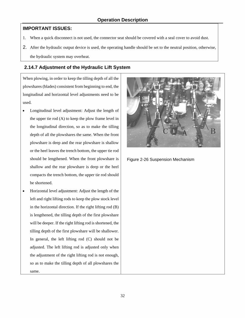
Figure 2-26 Suspension Mechanism
IMPORTANT ISSUES:
1. When a quick disconnect is not used, the connector seat should be covered with a seal cover to avoid dust.
2. After the hydraulic output device is used, the operating handle should be set to the neutral position, otherwise,
the hydraulic system may overheat.
2.14.7 Adjustment of the Hydraulic Lift System
When plowing, in order to keep the tilling depth of all the
plowshares (blades) consistent from beginning to end, the
longitudinal and horizontal level adjustments need to be
used.
• Longitudinal level adjustment: Adjust the length of
the upper tie rod (A) to keep the plow frame level in
the longitudinal direction, so as to make the tilling
depth of all the plowshares the same. When the front
plowshare is deep and the rear plowshare is shallow
or the heel leaves the trench bottom, the upper tie rod
should be lengthened. When the front plowshare is
shallow and the rear plowshare is deep or the heel
compacts the trench bottom, the upper tie rod should
be shortened.
• Horizontal level adjustment: Adjust the length of the
left and right lifting rods to keep the plow stock level
in the horizontal direction. If the right lifting rod (B)
is lengthened, the tilling depth of the first plowshare
will be deeper. If the right lifting rod is shortened, the
tilling depth of the first plowshare will be shallower.
In general, the left lifting rod (C) should not be
adjusted. The left lifting rod is adjusted only when
the adjustment of the right lifting rod is not enough,
so as to make the tilling depth of all plowshares the
same.

Operation Description
33
IMPORTANT ISSUES 1. When plowing, never adjust the traction of the farm machinery by adjusting the limit rod. Instead, reduce the
number of plowshares (blades) to match the tractor’s pulling capacity. This will help you avoid damaging the
suspension mechanism.
2. In order to avoid damage to the implement suspension mechanism when plowing, the tractor should never be
turned without lifting the farm implement it is towing.
NOTE: The sway bars are mainly used to prevent impact on the rear wheels of the tractor caused by an overlarge
swing of the lower tie rod when the tractor turns around at the end of a field with a lifted farm implement in tow.
When the farm implements are in the plowing position, the sway bars are in a loose state. Therefore, a certain
amount of swing between the tractor and the farm implement is allowed.

Operation Description
34
2.14.8 Power Take Off (PTO) Shaft Use
To connect and disconnect power to the power take off (PTO) shaft the double-acting clutch, the PTO gear shift
handle, and the PTO disconnect control handle are used. When the clutch pedal is pushed down part way it
disconnects the engine clutch, and when it is pushed down all the way down it disconnects the PTO clutch. When
the PTO gear shift handle is pushed forwards, it will be in high gear. When the PTO handle is pulled backwards, it
will be in low gear. Use the following method:
• Remove the rear hitch (only when using the 3-point configuration) and the protective cover on the power take
off (PTO) shaft and connect the farm implement drive to the PTO shaft on the tractor.
• Depress the clutch pedal to the floor to disconnect the PTO clutch and put the PTO gear shift handle in the
required position (high or low).
• Depress the clutch pedal to the floor again and turn the PTO disconnect control handle to the “connected”
position.
• Release the clutch pedal slowly. First operate with the throttle at low speed to check whether the PTO is
working properly.
• When repeated work in the same place within a short time frame is required, step on the clutch pedal gently to
disconnect the main clutch. This cuts off the power to the tractor transmission, and the tractor stays in one
place while the farm implement behind it can still work normally.
• To disconnect the PTO depress the clutch pedal to the floor and turn the PTO disconnect control handle to the
“disconnected” position. The PTO gear shift handle does not need to be moved. The PTO shaft will stop
turning.
• After disconnecting the farm implement from the PTO shaft, reinstall the protective cover over the PTO shaft.
Replace the rear hitch if it had been removed.
WARNING: Do not attach or detach anything from the PTO shaft while it is turning. Attempting to do
so can cause damage to the equipment and serious injury.
2.14.9 Electrical Equipment Use
The electrical system of 35XT Series Tractors uses 12V negative double bond cables.
Operation Description
35
2.14.9.1 Battery
The battery is used to store the electrical energy produced by the alternator. The battery can then supply electrical
power to the electrical equipment on the tractor when the alternator is not turning or is running at low speed. It can
also help with the power supply when the alternator is overloaded for a brief period.
• Frequently remove the dust and mud on the battery shell to avoid electric leakage. Check whether there are any
cracks in the battery case and/or leakage of electrolytes. Ensure good contact between the terminals and the
battery cables. The air vent on the plastic cover should not be blocked in order to avoid an explosion.
• Frequently check the battery voltage. Charge it when the voltage is low.
• The starter cranking time should not exceed 5 seconds each time to avoid excessive discharging.
• If the tractor is not used for a long time, the battery should be removed for charging and maintenance.
2.14.9.2 Alternator
• The alternator must be used with a matching regulator.
• The silicon rectification alternator is minus “—” grounded. The connection of the positive and negative poles of
the alternator, the regulator and the battery must be correct to avoid burnout of the alternator and the regulator.
• Do not strike sparks to determine whether the alternator is generating electricity.
• Remove the key from the ignition switch when the tractor is stopped to cut off the connection between the motor
and the battery and prevent the battery from discharging over an extended period of time.
2.14.9.3 Starter
• The starter should not run for an extended period. The starting time should not exceed 5 seconds each time to
avoid damage to the starter.
• If a grinding sound (teeth colliding) between the small gear on the starter and the flywheel ring gear is heard
when starting, turn the key back to its original position immediately and try again.
• If the starter continues running after the key is back to its original position, shut down the engine immediately and
start again after the fault is remedied.

Operation Description
36

Operation Description
38
2.15 Tractor Break-in
Before the tractor is put into service, it should run for a certain period under the specified conditions of
lubrication, rotational speed and load, and at the same time have any necessary inspection, adjustments and
maintenance, to normalize its technical state; a process called break-in. If the break-in procedure is not followed
the warranty may be void.
2.15.1 Break-in Preparations
• Perform per shift technical maintenance and 50 hour technical maintenance for the tractor during break-in.
(See “Maintenance Instructions” in this Operation Manual).
• Check and tighten the bolts, nuts and screws of the tractor.
• Add grease to the grease cups of the front wheel hub, the kingpin of the front drive axle and the water pump
shaft. Check the oil level of the engine oil pan, the transmission mechanism and lifter, and the central drive
and final drive of the front drive axle. Add oil according to the specifications if necessary.
• Fill the tractor with adequate fuel and coolant according to the specifications.
• Check the tire pressure.
• Check whether the electrical wiring is connected correctly and reliably.
• Put all control handles in neutral.
2.15.2 Engine Idle Break-in
Implement a 15 minute idle break-in for the engine. After starting the engine in the sequence specified in the
Diesel Engine Use and Maintenance Manual, run the engine in three stages, i.e. low speed (the up position of the
accelerator), then medium speed (the medium position of the accelerator) and finally high speed (the down
position of the accelerator). Do each for 5 minutes. The throttle control handle can be used to set a constant engine
speed at all three stages.
During the engine idle break-in, check the state of the engine and the hydraulic oil pump carefully to determine
whether there are any abnormal sounds or any leakage of water, oil or air. Make sure that the instruments are
functioning normally. If any abnormalities are found, immediately stop the tractor to eliminate the faults, and then
continue the break-in process.

Operation Description
39
The following types of break-in should not be implemented unless the engine is functioning normally.
2.15.3 Power Take Off Shaft Idle Break-in Put the throttle control handle in the medium position and let the engine run at medium speed. Let the power take
off shaft run 5 minutes in low speed and 5 minutes in high speed and check for abnormalities. After break-in, the
power take off shaft should be placed in the neutral position.
2.15.4 Hydraulic System Break-in
Start the engine and put the throttle control handle in the medium position for operation. Move the 3-point hitch
control handle and raise and lower the hitch several times to check for abnormalities. Then hang a load of 300kg
(660 lbs) or a farm implement with an equivalent weight on the hitch to make the engine run in the down position
of the accelerator. Move the 3-point hitch control handle to raise and lower the hitch 20 times at a minimum.
Check whether the hydraulic hitch can be held in the various positions. Check how long it takes to raise and lower
the hitch while checking for any leakage.
With the tractor static, make the engine run in low, medium and high speed, and move the steering wheel steadily
to the left and to the right 10 times each. Check whether the sound is normal and the steering wheel motion is
smooth and easy
If any faults are found during the running in, find out the causes promptly and repair.
Operation Description
40
2.15.5 Tractor Idle and Loaded Break-In
After the engine idle, power take off shaft and hydraulic system break-in tests, confirm that the mechanical state
of the tractor is normal before implementing the break-in of the whole tractor according to Tables 2-2 and 2-3.
The total break-in time is 50 hours. During idle break-in, make turns at low speed and use the one-side brake
properly. Also test the emergency brake at high speed.
After idle break-in, loaded break-in can be performed, but only if the mechanical state of the tractor is normal.
This process should be carried out with the load from light to heavy and the gear range from low to high. During
the break-in, note if:
• The readings of electrical equipment and various instruments are normal.
• The engine is running normal.
• The engagement of the clutch is smooth and the disengagement is complete.
• Gear shifting is easy and flexible, free of gear problems.
• The brakes work reliably.
• The connection and disconnection of the differential lock is reliable.
• The connection and disconnection of the front drive axle is reliable.
If faults are found, repair them before continuing the break-in process.
2.15.6 Technical Maintenance after Break-In After the break-in of the tractor, there may be some debris mixed in the oil in the transmission, the lubrication
system and the hydraulic system.
Therefore, all lubricating oil and hydraulic system oil should be drained and replaced. Take care of any necessary
technical maintenance for the tractor before putting it in to normal use. Technical maintenance after break-in
includes:
• After the engine stops, drain the oil from the engine oil pan and the steering mechanism oil tank before it
cools down. Use approved containers to collect the used oil, and dispose of it properly.
• Replace the engine oil filter and the diesel fuel filter, and clean the air filter.
• Add new lubricating oil according to the technical requirements after the diesel fuel filter and the engine oil
filter are replaced.
• After reinstalling the 3-point lift oil absorption filter, add new oil to the 3-point lift, the transmission, and the
Operation Description
41
front drive axle according to the specifications.
• Carry out the technical maintenance for the diesel engine according to the specifications of the Diesel Engine
Use and Maintenance Operation Manual.
• Drain the engine coolant then add new coolant, with a 50/50 water/antifreeze mixture. Never run the engine
without coolant in the cooling system.
• Check the toe-in of the front wheels and the free play of the clutch and brake pedals. Adjust them if
necessary.
• Check all bolts, nuts and screws and tighten if necessary.
• Add grease to each grease fitting on the tractor according to the maintenance table.
IMPORTANT ISSUES:
1. Tractors that have just left the factory, or have just been overhauled, should be broken-in before they are put into
normal service. Otherwise, their service lives will be reduced.
2. Drivers should first learn and master the operations of the tractor before doing the break-in.

Maintenance Instructions
41
Table 2-1 Break-in Time for Each Stage Unit: hours
2.16 Tractor Faults and Troubleshooting
2.16.1 Chassis Faults and Troubleshooting
2.16.1.1 Clutch Faults and Troubleshooting
Table 2-2 Clutch Faults and Troubleshooting
Fault Causes Troubleshooting
1. The clutch slips.
(1) The clutch plate and pressure plate are dirty or greasy. (2) The clutch plate is excessively worn or burnt. (3) The Belleville spring pressure is too low. (4) The free play of the pedal is too small or there is no free play. (5) The clutch fingers are badly deformed.
(1) Clean with solvent. Find the cause and eliminate the fault. (2) Replace the clutch plate. (3) Replace the spring. (4) Re-adjust the free play of the pedal according to the specifications. (5) Replace the clutch fingers.
2. The clutch does not disengage completely, and noise is heard when it is engaged.
(1) The free play of the pedal is too large and the working play is too small. (2) The clutch fingers are excessively warped. (3) The heads of the three clutch fingers are not in the same plane.
(1) Adjust the free play of the pedal according to the specifications. (2) Replace the clutch fingers. (3) Adjust according to requirements.
Forward Gear Reverse Gear Tractor Gear
Low
1
Low
2
Low
3
Low
4
High
1
High
2
High
3
High
4
Low
1
Low
2
Low
3
Low
4
High
1
High
2
High
3
High
4
Idle, no load 0.5 0.5 0.5 0.5 0.5 0.5 0.5 0.5 0.5 0.5 0.5 0.5 0.5 0.5 0.5 0.5
Loaded with 3t weight with a trailer, road transportation should be used
4 4.5 5 5 2.5
Operating on sandy soil with a plow, tilling depth 14cm (5.5 in)
5 5 5 5 4

Maintenance Instructions
42
Fault Causes Troubleshooting
3. The tractor shakes when starting.
(1) The heads of the three clutch fingers are not in the same plane. (2) The clutch plate and the clutch fingers have grease on them. (3) The clutch fingers are warped. (4) The fastening screw for the flywheel and the clutch has come loose.
(1) Make adjustments according to requirements. (2) Clean the friction plate and the clutch fingers with solvent. (3) Replace the clutch fingers. (4) Stop the tractor immediately and repair the fault.
2.16.1.2 Gearbox Faults and Troubleshooting
Table 2-3 Gearbox Faults and Troubleshooting Fault Causes Troubleshooting
1. Putting the tractor into gear is difficult or impossible.
(1) Clutch has not disengaged completely. (2) Gearshift interlocking rod is too long. (3) The shift lever fork is severely worn. (4) The end face of the engagement sleeve or the end face of the gear is worn or broken.
(1) Troubleshoot according to the clutch type. (2) Shorten the gearshift interlocking pull rod. (3) Replace the shift lever. (4) Replace or repair.
2. Gearshift disengages automatically.
(1) The gearshift interlocking rod is too short. (2) The locating slot of the shifting fork shaft is severely worn. (3) The spring pressure of the interlocking latch is insufficient. (4) The bearing on the gear shaft is worn, making the shaft tilt. (5) The spline of the tooth holder is worn.
(1) Lengthen the gearshift interlocking pull rod. (2) Replace the shift fork. (3) Adjust or replace the interlocking pin spring. (4) Replace the bearing. (5)Replace the tooth holder.
3. Random gear shifting.
(1) The shift lever fork is worn. (2) The gear guide plate is severely worn. (3) The fork slot of the shifting fork and the meshing bush are worn. (4) Locating pin of interlocking pin and shift fork is severely worn.
(1) Repair or replace the shift lever. (2) Replace the gearbox guide plate. (3) Replace the shifting fork and the meshing bushing. (4) Replace the interlocking pin and the shift fork shaft.
4. Noise or impact sound from the gear box.
(1) The gear is excessively worn and/or the tooth surface has chipped off. (2) The bearing is badly worn or damaged. (3) The lubricating oil is insufficient or oil quality does not conform to the specifications.
(1) Replace the gear. (2) Replace the bearing. (3) Fill or replace lube oil.

Maintenance Instructions
43
2.16.1.3 Rear Axle and Brake Faults and Troubleshooting
Table 2-4 Rear Axle and Brake Faults and Troubleshooting
Fault Causes Troubleshooting
1. Increased noise in the central drive.
(1) The bearing play of the small conical gear is too large. (2) Gear engagement is abnormal. (3) The bearing of the conical gear pair or the gear pair is damaged. (4) The differential shaft is worn or locked. (5) The planetary gear or gasket is worn. (6) The differential bearing is worn or damaged.
(1) Adjust according to requirements. (2) Readjust according to requirements. (3) Replace the bearing or the gear. (4) Replace the differential gear shaft. (5) Replace the planetary gear or shim. (6) Replace the differential bearing.
2. Small conical gear and the differential bearing overheat.
(1) The pre-load force is too high. (2) Poor lubrication. (3) Backlash at gear pair side of conical gear is too small.
(1) Readjust the pre-load force of the bearing. (2) Check the lubricating oil level and add if necessary. (3) Readjust the gear backlash.
3. Abnormal noises from the final drive..
(1) The bearing, gear or shaft is damaged. (1) Replace the bearing, gear or shaft.
4. No braking control.
(1) The free play of the brake pedal is too large. (2) The brake shoes are severely worn or warped. (3) The engagement of the brake pedal is misadjusted.
(1) Readjust the free play of the brake pedal. (2) Replace the brake shoes. (3) Adjust the engagement of the brake pedal according to the specifications.
5. Brakes get hot. (1) The brake shoes do not return. (2) The brake shoes do not completely disengage from the brake drums.
(1) Replace the return spring. (2) Make adjustments according to requirements.
6. The tractor pulls in one direction when braking.
(1) The free play of the left and right brake pedals are not the same. (2) The brake shoes on one side str damaged or worn unevenly. (3) The air pressure of the two rear tires is not the same.
(1) Adjust. (2) Replace the brake shoes. (3) Check and inflate the tires according to the specifications.

Maintenance Instructions
44
2.16.1.4 Four-Wheel Drive System Faults and Troubleshooting
Table 2-5 Four-Wheel Drive System Faults and Troubleshooting
Fault Causes Troubleshooting
1. The front tire has excessive wear.
(1) The rim or the radial plate of the front wheel is deformed. (2) The toe-in has been improperly adjusted. (3) The bearing pins of the steering knuckle and the oil cylinder are severely worn. (4) The tire pressure is too low. (5) The front drive axle does not disengage during operation. (6) The drive tread of the front tire is mounted backwards.
(1) Align the front wheel rim or the radial plate. (2) Adjust the toe-in. (3) Replace the bearing pin(s). (4) Inflate the tires according to the specifications. (5) Disengage the front drive axle or repair it. (6)Reinstall the tire according to requirements.
2. The front wheel shakes.
(1) The fastening nuts and bolts for the ball pins, king pin, oil cylinder or the steering arm are loose.
(2) The toe-in has been improperly adjusted. (3) The clearance of the bearing is too great,
or the bearing is severely worn. (4) The rim of the front wheel is severely
deformed.
(1) Check and tighten. (2) Adjust the toe-in. (3) Adjust or replace the bearing. (4) Align or replace the front wheel rim.
3. Loud noise (four wheel drive tractors)..
(1) Engagement trace of the front central drive gear is bad. (2) The clearance of the central drive bearing is too great or the bearing is damaged. (3) The differential axle is worn or damaged. (4) The planetary gear or gasket is worn. (5) The meshing of the final planetary gear pair is bad.
(1) Readjust the gear meshing backlash. (2) Adjust or replace. (3) Replace the differential axle. (4) Replace the planetary gear or the shims. (5) Replace the planetary drive gear.
4. The drive shaft and sleeve overheat.
(1) The transmission shaft is severely bent or deformed, creating friction.
(1) Replace the transmission drive shaft.
5. Loud noise in the transfer case.
(1) Using too high a gear. (2) The bearing or the gear is badly worn.
(1) Put into low gear. (2) Replace.

Maintenance Instructions
45
2.16.1.5 Hydraulic Steering System Faults and Troubleshooting
Table 2-6 Hydraulic Steering System Faults and Troubleshooting
Fault Causes Troubleshooting
1. Oil leak.
(1) Rubber O-rings at various pipe joints are damaged or loose. (2) O-rings in hydraulic steering gear valve body, stator and rear cover are damaged. (3) The O-ring at the axle journal is damaged. (4) The bolts at the joint of the steering rack or the hub subassembly have loosened.
(1) Replace the O-ring or tighten the fitting. (2) Clean or replace the O- ring. (3) Replace the O- ring. (4) Tighten the bolts.
2. Heavy steering.
(1) The oil supply to the gear oil pump is insufficient, or the gear oil pump leaks inside or the filter screen in the steering oil tank is blocked. The steering is light at low speed and heavy high at speed. (2) Erratic steering cylinder movement when the steering wheel is turned. (3) The oil level in the steering oil cylinder is too low. (4) The spring tension in the relief valve has weakened, or the steel ball is not seated correctly. With a light load the steering is light but the steering becomes heavier as the load increases. (5) Oil viscosity is too thick. (6) Steel ball check valve in the valve body has failed. The steering is heavy when turning slowly or weak when turning sharply (7) Oil leakage from the steering system, both inside and outside.
(1) Check the gear oil pump. Clean the filter screen. (2) Discharge the air from the system and check whether there is air or an air leak in the oil suction pipe. (3) Fill oil to specified height, clean the relief valve and adjust the spring pressure in the relief valve. (4) Replace defective relief valve components. (5) Drain oil and replace with the specified oil. (6) Replace valve. (7) Troubleshoot to find the location of the oil leak and repair or replace leaking components.
3. Steering fails.
(1) The king pin is broken or deformed. (2) Rotor and linkage shafts are improperly mounted. (3) Steering cylinder or piston seal ring is damaged.
(1) Replace the king pin. (2) Refit and realign. (3) Replace the piston or the seal ring.
4. Power steering fails..
(1) The clearance between the rotor and the stator on the pump is too large. (2) During power steering, the driver cannot feel the endpoints of the extreme steering positions. During manual steering, the steering wheel turns but the steering cylinder does not move.
(1) Replace the pump. (2) Replace the seal ring on the piston.

Maintenance Instructions
46
5. Steering is slow to respond or hard to turn.
(1) The clearance between the valve core and the valve housing is too large. (2) The clearance between the interlocking shaft and the fork pin is too large. (3) The clearance between the interlocking shaft and the rotor is too large. (4) The return spring is broken or too soft.
(1) Replace valve. (2) Replace shaft or pin. (3) Replace shaft or rotor. (4) Replace.spring.
2.16.1.6 Hydraulic Hitch System Faults and Troubleshooting
Table 2-7 Hydraulic Hitch System Faults and Troubleshooting
Fault Causes Troubleshooting
1. Unable to lift either a light or heavy load.
(1) The oil level within the 3-point lift is too low. (2) The strainer of the oil filter is blocked. (3) Air is getting into the oil suction line. (4) Gear oil pump failure. (5) Spring pin on the outside/inside end of the operation handle has fallen out. (6) The swing rod inside the hydraulic distributor dropped. (7).The main control valve seized at the middle or lowering position, or the oil return valve seized in the open position. (8) Main control valve seized. (9) Lowering valve seized. (10) Pin shortened, or lowering valve assembly comes loose making it unable to open the lowering valve. (11) The oil passage from the cylinder end to oil cylinder is closed.
(1) Add oil to the specified oil level. (2) Clean or replace the strainer on the oil filter. (3) Check for air leaks. (4) Replace the geared oil pump. (5) Reinstall the spring pin. (6) Open the distributor, and install the swing rod. (7) Take apart the distributor, and clean each valve. (8) Clean main control valve. (9) Clean lowering valve. (10) Remove plug for lowering valve, readjust the clearance of the lowering valve push pin or tighten the lowering valve assembly. (11) Open the oil passage.
2. Light load can be lifted, but heavy load cannot be
lifted or lifts slowly.
(1) Air is entering the oil suction line. (2) Adjustment pressure of the system safety valve is too low. (3) Adjustment pressure of the oil cylinder safety valve is too low. (4) Gear oil pump is worn or pressure is inadequate. (5) Oil cylinder seal ring is leaking.
(1)Check the oil suction pipe and oil filter. (2) Replace the system safety valve. (3) Replace the oil cylinder safety valve. (4) Replace the geared oil pump. (5) Replace the seal ring on the oil cylinder.
3. Farm implements shake during lifting and/or lift
slowly.
(1) Oil filter is blocked. (2) Air getting into the oil suction pipe.
(1) Replace the filter element. (2) Replace the O-ring seal. (3) Replace the gear oil pump.

Maintenance Instructions
47
Fault Causes Troubleshooting
(3) Gear oil pump failure. (4) Hydraulic oil level is too low.
(4) Add lubricating oil according to the requirements.
4. Farm implements slowly drop after being lifted, and the descent becomes faster after turning off the engine.
(1) The tightness of the check valve in the hydraulic flow hydraulic flow distributor is poor. (2) The lowering valve is not sealed tightly. (3)The oil cylinder safety valve leaks oil or is not adjusted properly. (4) The O-ring for the oil cylinder is damaged or leaking. (5) The seal ring between the distributor or the cylinder head and the oil inlet hole on the 3-point lifter shell is improperly installed or damaged.
(1) Clean the check valve. (2) Clean or replace the lowering valve. (3) Repair or readjust the safety valve on the oil cylinder. (4) Replace the O-ring. (5) Check and replace the seal ring.
5. With the 3-point lift lever at lifting position, the
hydraulic distributor makes a loud noise.
(1) Because of improper adjustment, the inner lifting arm props against the lifter case to open the safety valve..
(1) First measure the lifting height of the farm implement. Then readjust and shorten the force/position adjusting rod to make the highest lifting position lower than the original position.
6. The 3-point hitch has no hydraulic pressure or weak
output.
(1) The oil cylinder inlet line has been disconnected. (2)The front cone and conical hole of the speed lowering control valve have not been sealed tightly. (3) Lifter is in the neutral lifting position.
(1) Tighten the lowering speed adjustment knob clockwise to reduce the lowering speed. (2) Replace the valve. (3) Push the lifter control handle to the lowering position to lower the outer lifting arm to the lowest position. Shut off the inlet oil line to the oil tank, and then put the operating lever in the lift position.
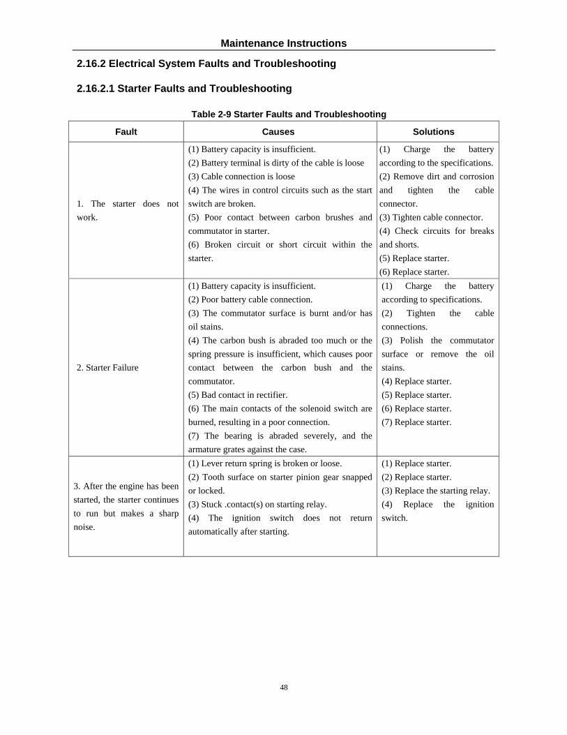
Maintenance Instructions
48
2.16.2 Electrical System Faults and Troubleshooting
2.16.2.1 Starter Faults and Troubleshooting
Table 2-9 Starter Faults and Troubleshooting
Fault Causes Solutions
1. The starter does not work.
(1) Battery capacity is insufficient. (2) Battery terminal is dirty of the cable is loose (3) Cable connection is loose (4) The wires in control circuits such as the start switch are broken. (5) Poor contact between carbon brushes and commutator in starter. (6) Broken circuit or short circuit within the starter.
(1) Charge the battery according to the specifications. (2) Remove dirt and corrosion and tighten the cable connector. (3) Tighten cable connector. (4) Check circuits for breaks and shorts. (5) Replace starter. (6) Replace starter.
2. Starter Failure
(1) Battery capacity is insufficient. (2) Poor battery cable connection. (3) The commutator surface is burnt and/or has oil stains. (4) The carbon bush is abraded too much or the spring pressure is insufficient, which causes poor contact between the carbon bush and the commutator. (5) Bad contact in rectifier. (6) The main contacts of the solenoid switch are burned, resulting in a poor connection. (7) The bearing is abraded severely, and the armature grates against the case.
(1) Charge the battery according to specifications. (2) Tighten the cable connections. (3) Polish the commutator surface or remove the oil stains. (4) Replace starter. (5) Replace starter. (6) Replace starter. (7) Replace starter.
3. After the engine has been started, the starter continues to run but makes a sharp noise.
(1) Lever return spring is broken or loose. (2) Tooth surface on starter pinion gear snapped or locked. (3) Stuck .contact(s) on starting relay. (4) The ignition switch does not return automatically after starting.
(1) Replace starter. (2) Replace starter. (3) Replace the starting relay. (4) Replace the ignition switch.

Maintenance Instructions
49
2.16.2.2 Alternator Faults and Troubleshooting
Table 2-10 Alternator Faults and Troubleshooting
Fault Causes Solutions
1. The alternator does not generate electricity.
(1) Wiring is wrong, broken, and/or making poor contact. (2) Rotor circuit broken. (3) Rectifier diode damaged. (4) Carbon bushes are not making proper contact.. (5) Regulator is damaged.
(1) Check and repair the circuits. (2) Replace alternator. (3) Replace alternator. (4).Replace alternator. (5).Replace alternator.
2. The alternator is not charging properly.
(1) The drive V-belt is loose. (2) Bad contact with the carbon brush and the commutator. (3) The regulator is damaged. (4) Not enough electrolytes in the battery or battery is sulfurized or too old.
(1) Adjust the tension of the drive V-belt. (2) Replace alternator. (3) Replace alternator. (4) Replace battery.
3. The alternator is overcharging.
Regulating voltage for the regulator is too high.
Replace the voltage regulator.
2.16.2.3 Battery Faults and Troubleshooting
Table 2-11 Battery Faults and Troubleshooting
Fault Causes Solutions
1. The battery capacity is low and the engine is hard to
start.
(1) Short circuit between electrode plates in the battery (2) Sulphurization of the electrode plates in the battery. (3). Poor circuit connector contact, or too much oxidation
(1) Replace battery. (2) Replace battery. (3) Clean battery terminal, securely fasten cable connector, and coat with a layer of petroleum jelly.
2. Excessive battery discharging.
(1) Impurities in the electrolytes. (2) Short circuits exist in the electrical system. (3) Short circuit caused by placement of a metal tool or bar between positive/negative posts. (4). Corrosion on battery terminals or cables.
(1) Replace battery. (2) Troubleshoot and repair. (3) Remove metal object, replace battery if necessary. (4) Clean and replace if necessary.

Maintenance Instructions
50
2.16.2.4 Instrument Faults and Troubleshooting
Table 2-12 Instruments Faults and Troubleshooting
Fault Causes Solutions
1. The water temperature gauge always indicates a
low temperature.
(1) Break in the circuit or the plug is making poor contact. (2) The water temperature sensor is damaged. (3) The water temperature gauge is broken.
(1) Overhaul the circuit, or remove the dirt at the plug. (2) Replace the water temperature sensor. (3) Replace the gauge.
2. The water temperature gauge always indicates a
high temperature.
(1) The water temperature sensor is damaged. (2) There is a broken circuit or a short circuit. (3) The water temperature gauge is broken.
(1) Replace the water temperature sensor. (2) Check and repair-circuit faults. (3) Replace the gauge.
3. The oil pressure gauge is abnormal.
(1) The oil pressure sensor is damaged. (2) There is broken circuit or a short circuit. (3) The oil pressure gauge is bad.
(1) Replace the oil pressure sensor. (2) Check and repair circuit faults. (3) Replace the gauge.
2.16.2.5 Headlight/Taillight/Work Light Faults and Troubleshooting
Table 2-13 Headlight/Taillight/Work Lights Faults and Troubleshooting
Fault Causes Solutions
1. The headlights have no high beam or low beam.
(1) Circuit broken, short circuit, or a blown fuse. (2) Bad contact or damage to the headlight switch. (3) Burned-out filament in bulb.
(1) Check and repair, then reconnect. (2) Check and replace if necessary. (3) Replace bulb.
2. The taillights do not work.
(1) Circuit broken, short circuit, or a blown fuse. (2) Bad contact or damage to the taillight/instrument light/work light switch. (3) Burned-out filament in bulb.
(1) Check and repair, then reconnect. (2) Check and replace if necessary. (3) Replace bulb.
3. The rear work lights or instrument lights do not
work.
(1) Circuit broken, short circuit, or a blown fuse. (2) Bad contact or damage to the taillight/instrument light/work lights switch. (3) Burned-out filament in bulb.
(1) Check and repair, then reconnect. (2) Check and replace if necessary. (3) Replace bulb.

Accessories and Consumables
51
3. Accessories and Consumables
3.1 Accessories
3.1.1 Safety Frame (optional) The 35XT series tractor can be equipped with an OSHA safety frame to prevent the driver from being hurt by an accidental turnover. 3.2 List of Consumables (Not Included With Tractor Purchase)
Table 3-1 List of Consumables, Such As Bulbs, Glass Products, Filters, etc.
Sequence No.
Code Description Quantity Remark
1 12V-1141-28W Rear lamp bulb 1 2 pieces applied to third gen. model
2 12V-1141-21W Front/rear turn signal bulbs 4 3 12V-89-5W Rear work light bulbs 2
4 12V-H4-55/60W Double-filament bulb for
high beam and low beam headlights
1
5 12V-1141-21W Brake light bulb 2
6 TE324.20A-01 O-ring for wire-roller 1
7 FT220.40.301 Steering rod seal boot 1
8 TE250.362D-01 Dust ring 1 Used for the type with shuttle shifter
9 FT250.47C.230 Machine cover seal 1 10 TE250.475B-01 Rubber sealing strip 1 11 YFKM385T10500 Fuel Filter Element 1 12 YFKM385T09300 Oil filter Element 1
IMPORTANT NOTE: 1. When repairing and maintaining the tractor, use the standard fasteners required by the
manufacturer. Use of substandard fittings may affect the tractor’s functions, service performance and service life and create hazardous situations.

Maintenance Instructions
52
4. Maintenance Instructions 4.1 Technical Maintenance Procedures Carrying out the technical maintenance specifications of the tractor is the effective way to prolong the service life
of the tractor and reduce accidents.
The technical maintenance schedule for 35XT series tractors is based on the accumulated work hours, which
includes maintenance for: every shift (per 10 work hours), every 50 work hours, every 200 work hours, every 400
work hours,every 800 work hours, every 1600 work hours, and winter and long-term storage.
IMPORTANT ISSUES: 1. All maintenance should be carried out by the owner/operator or a trained service professional who is
familiar with the tractor.
2. In order to make the tractor work properly and to prolong its service life, technical maintenance
procedures must be strictly observed during running-in and normal operation.
3. The tractor warranty can be voided at any time should damage happen as the result of any operator who
is unfamiliar with the tractor or when specified maintenance procedures are not performed according to
manufacturer specified timelines.
4. Opening the engine and hydraulic system safety valve, the relief valve, and the voltage regulator
are prohibited, without prior manufacturer authorization. Making adjustments to these sensitive areas
may cause damage to the tractor, and invalidate the warranty.
4.1.1 Technical Maintenance for Every Shift (every 10 hours) 1. Remove the dust, oil, and dirt from the tractor, and clean the air filter when working under dusty
conditions.
2. Check whether the bolts and nuts on the outside of the tractor are loose and tighten them if necessary,
especially the nuts of the front and rear wheels.
3. Check the oil level in the engine oil pan, and fluid levels in the radiator, fuel tank, power steering
reservoir, and hydraulic lifter. Add the correct fluid to each of them when the level is low. The tractor
should be parked for at least 30 minutes on a level surface before checking the engine oil level.
4. Grease according to Table 4-1.
5. Check if the engine has any air, oil or water leakage, and eliminate the leakage if any exists.
6. Check the pressure of the front and rear tires, and add air to them when necessary.
7. Check and adjust the free play of the clutch and brake pedals.
8. Maintain the diesel engine according to the requirements for daily maintenance described in the engine
manual.

Maintenance Instructions
53
4.1.2 Technical Maintenance for Every 50 Hours 1. Perform all the requirements of the technical maintenance per shift.
2. Check the air filter and remove the dust.
3. Check the tightness of the fan belt. When pressing the belt, it should deflect 15 - 20mm
(0.6 - 0.8 in.). Adjust if necessary.
4. The terminals on the battery should be coated with grease to prevent corrosion.
5. Maintain the diesel engine according to the requirements of level 1 technical maintenance" specified in
the engine manual.
4.1.3 Technical Maintenance for Every 200 Hours 1. Perform all technical maintenance required for every 50 work hours.
2. Lubricate all grease fittings according to Table 4-1.
3. Change the diesel engine oil, clean the engine oil pan and the filter screen, and change the oil filter.
4. Replace the air filter element.
5. Clean the oil filter of the lifter, and replace the filter element, if necessary.
6. Carry out maintenance of the diesel engine according to the requirements of the level 2 technical
maintenance specified in the engine manual.
4.1.4 Technical Maintenance for Every 400 Hours 1. Perform all technical maintenance required for every 200 work hours.
2. Check the oil level in the transmission case, and add oil if necessary. 3. Check the oil surface level in the front drive axle, and add oil if necessary. 4. Check the tightness of the toe-in of the front wheel and the front wheel bearing, and adjust the tightness if
necessary. Replace the lubricating oil inside the front wheel hubs. 5. Check the angle of the steering wheel during idle running, adjust the angle if necessary. 6. Clean and maintain the hydraulic system filter. 7. Carry out maintenance of the diesel engine according to the requirements of the level 3 maintenance
specified in the engine manual.
4.1.5 Technical Maintenance for Every 800 Hours 1. Perform all technical maintenance required for every 400 work hours. 2. Change the hydraulic system oil. 3. Flush cooling system and radiator. Refill with a 50/50 water/anti-freeze mixture. 4. Clean the transmission case and change the oil in the transmission when the tractor is warm. 5. Clean the oil suction filter screen of the hydraulic system, and check the cleanliness of the hydraulic oil.
When necessary, drain the sump of the lifter case, clean it with solvent, and change the oil.
6. Check and adjust the clearance of the engine valves.
7. Drain and clean the fuel tank and the filter in the fuel tank.
8. Carry out maintenance of the diesel engine according to the requirements of the level 4 maintenance
specified in the engine manual.

Maintenance Instructions
54
4.1.6 Technical Maintenance for Every 1600 Hours 1. Perform all technical maintenance required for every 800 work hours.
2. Check engine to manufacturer’s specifications.
3. Change the lube oil in the central drive and the final drive of the front drive axle.
4. Check for bearing noise in the clutch and front end.
5. Check whether the clearance and contact points of the central transmission gears are normal. Check the
clearance and pre-loading condition of bearings, and adjust if necessary.
6. After completing the maintenance, assemble the whole machine and carry out a short-term trial run.
Check and adjust each mechanism as necessary.
4.1.7 Special Maintenance in Winter When the temperature is below freezing, along with the "Technical Maintenance per Shift", the following provisions should be strictly observed: 1. Select winter grade fuel and lubricating oil.
2. Check the strength of the coolant with a hydrometer. If necessary add anti-freeze to the cooling system as
required to protect against coolant freezing.
3. At the start of every shift start the engine in accordance with winter starting procedures.
4. In order to protect the tractor and ensure that the engine is easy to start, it is recommended that the tractor
be parked in an insulated machine shed or garage during cold periods.
4.1.8 Tractor Maintenance During Long-term Storage Periods 1. If the tractor is going to be kept in storage less than 1 month, and the time since the last oil change does
not exceed 100 hours of running time, special technical maintenance is not required. If the tractor is
going to be kept in storage longer than 1 month, special technical maintenance should be performed
according to Section 5 – Storage as specified in this manual..
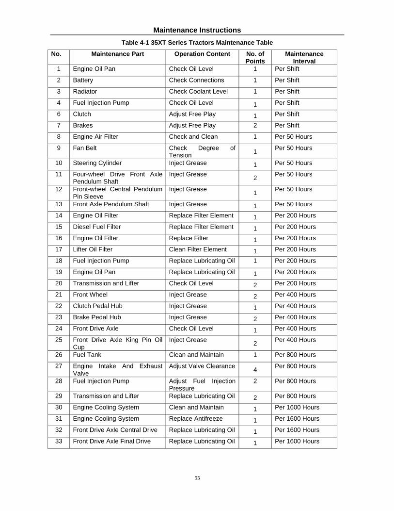
Maintenance Instructions
55
Table 4-1 35XT Series Tractors Maintenance Table No. Maintenance Part Operation Content No. of
Points Maintenance
Interval 1 Engine Oil Pan Check Oil Level 1 Per Shift
2 Battery Check Connections 1 Per Shift
3 Radiator Check Coolant Level 1 Per Shift
4 Fuel Injection Pump Check Oil Level 1 Per Shift
6 Clutch Adjust Free Play 1 Per Shift
7 Brakes Adjust Free Play 2 Per Shift
8 Engine Air Filter Check and Clean 1 Per 50 Hours
9 Fan Belt Check Degree of Tension 1 Per 50 Hours
10 Steering Cylinder Inject Grease 1 Per 50 Hours
11 Four-wheel Drive Front Axle Pendulum Shaft
Inject Grease 2 Per 50 Hours
12 Front-wheel Central Pendulum Pin Sleeve
Inject Grease 1 Per 50 Hours
13 Front Axle Pendulum Shaft Inject Grease 1 Per 50 Hours
14 Engine Oil Filter Replace Filter Element 1 Per 200 Hours
15 Diesel Fuel Filter Replace Filter Element 1 Per 200 Hours
16 Engine Oil Filter Replace Filter 1 Per 200 Hours
17 Lifter Oil Filter Clean Filter Element 1 Per 200 Hours
18 Fuel Injection Pump Replace Lubricating Oil 1 Per 200 Hours
19 Engine Oil Pan Replace Lubricating Oil 1 Per 200 Hours
20 Transmission and Lifter Check Oil Level 2 Per 200 Hours
21 Front Wheel Inject Grease 2 Per 400 Hours
22 Clutch Pedal Hub Inject Grease 1 Per 400 Hours
23 Brake Pedal Hub Inject Grease 2 Per 400 Hours
24 Front Drive Axle Check Oil Level 1 Per 400 Hours
25 Front Drive Axle King Pin Oil Cup
Inject Grease 2 Per 400 Hours
26 Fuel Tank Clean and Maintain 1 Per 800 Hours
27 Engine Intake And Exhaust Valve
Adjust Valve Clearance 4 Per 800 Hours
28 Fuel Injection Pump Adjust Fuel Injection Pressure
2 Per 800 Hours
29 Transmission and Lifter Replace Lubricating Oil 2 Per 800 Hours
30 Engine Cooling System Clean and Maintain 1 Per 1600 Hours
31 Engine Cooling System Replace Antifreeze 1 Per 1600 Hours
32 Front Drive Axle Central Drive Replace Lubricating Oil 1 Per 1600 Hours
33 Front Drive Axle Final Drive Replace Lubricating Oil 1 Per 1600 Hours

Maintenance Instructions
56
4.2 Clutch Adjustment
In order to ensure the normal operation of the clutch, a
clearance of (2–2.5mm) should be kept between the end
of disengaging lever 4 of the main clutch and the surface
of release bearing 5; a clearance of B = (10–11mm)
should be kept between the end of disengaging lever 6
of the auxiliary clutch and the surface of release bearing
5. During use, because of the continuous abrasion of the
clutch friction plates, the clearance mentioned above
will gradually narrow or disappear. Therefore,
inspection and adjustment should be carried out
regularly.
1. The adjustment method for adjusting the play of the
clutch pedal is as follows:
First loosen the lock nut (3) on the adjustment screw (2)
(see Figure 4-1), Rotate the adjustment screw (2).
Adjust the distance between the working surface of the
three main clutch disengaging levers (4) and the clutch
pressure plate (1), make the distance A=(86.5+0.2mm)
for 25PS models, and A=(91.5+0.2mm) for 30PS or
35PS models. Tighten the lock nut (3). Loosen the nuts
(7 and 8), and rotate the adjustment screw (8). Make the
distance between the working surfaces of the auxiliary
clutch disengaging lever (6) and the clutch pressure
plate (1) to be C=(78.5+0.2mm) for 25PS models, and
C=(93+0.2mm) for 30PS or 35PS models. Tighten the
nut (8). Make sure that the free play of the clutch pedal
is (25–30mm) by adjusting the clutch rod front fork (4)
(see Figure 4-2), and tighten the nut (5) after the
adjustment (see Figure 4-2).
2. The adjustment method for the throw of the clutch
pedal is as follows:
Loosen the lock nut (1) (See Fig. 4-2) and rotate the
limit screw (2). Make the throw under the clutch rocker
arm (3) to be 35–37mm and tighten the lock nut (1).
Figure 4-1 Clutch
1. Pressure Plate 2. Adjustment Screw 3. Lock Nut 4. Main Clutch Disengaging Lever 5. Release Bearing 6. Auxiliary Clutch Disengaging Lever 7. Nut 8. Nut
Figure 4-2 Clutch Control System Schematic
Diagram 1. Lock Nut 2. Limit Screw 3. Clutch Rocker
Arm 4. Rod Front Fork 5. Nut 6. Clutch Pedal
7. Lock Nut 8. Interlocking Tie Rod
Note: 25.4mm = 1 inch

Maintenance Instructions
57
IMPORTANT ISSUES:
1. Adjusting the clutch requires technical skills and specific tools. If uncomfortable completing this task
call NorTrac Technical Support.
2. In order to keep the friction plate from the oil, keep drain hole clear of any blockage below the flywheel
casing. If serious leakage is found, repair immediately. Use solvent to clean the friction plate if
necessary.
3. In order to avoid friction plate abrasion, the clutch should be maintained and adjusted frequently; don’t
release and engage the clutch randomly; when releasing the clutch, step on the clutch pedal rapidly to set
the limit. Never run the tractor when the clutch is semi-engaged as this will damage the clutch.
4. Never use the tractor when the clutch is not adjusted properly. This will speed up abrasion of the clutch
friction plate and possibly burn the friction plate.
5. When installing the clutch, fill with lithium base grease in the internal cavity of the release bearing
support.
6. When dismantling the clutch, replace the release bearing and the throwout bearing.
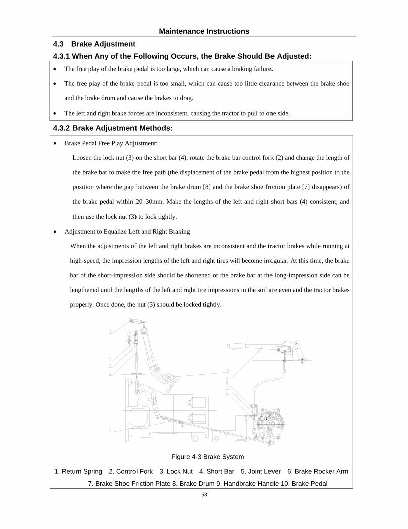
Maintenance Instructions
58
4.3 Brake Adjustment 4.3.1 When Any of the Following Occurs, the Brake Should Be Adjusted: • The free play of the brake pedal is too large, which can cause a braking failure.
• The free play of the brake pedal is too small, which can cause too little clearance between the brake shoe
and the brake drum and cause the brakes to drag.
• The left and right brake forces are inconsistent, causing the tractor to pull to one side.
4.3.2 Brake Adjustment Methods:
• Brake Pedal Free Play Adjustment:
Loosen the lock nut (3) on the short bar (4), rotate the brake bar control fork (2) and change the length of
the brake bar to make the free path (the displacement of the brake pedal from the highest position to the
position where the gap between the brake drum [8] and the brake shoe friction plate [7] disappears) of
the brake pedal within 20–30mm. Make the lengths of the left and right short bars (4) consistent, and
then use the lock nut (3) to lock tightly.
• Adjustment to Equalize Left and Right Braking
When the adjustments of the left and right brakes are inconsistent and the tractor brakes while running at
high-speed, the impression lengths of the left and right tires will become irregular. At this time, the brake
bar of the short-impression side should be shortened or the brake bar at the long-impression side can be
lengthened until the lengths of the left and right tire impressions in the soil are even and the tractor brakes
properly. Once done, the nut (3) should be locked tightly.
Figure 4-3 Brake System
1. Return Spring 2. Control Fork 3. Lock Nut 4. Short Bar 5. Joint Lever 6. Brake Rocker Arm
7. Brake Shoe Friction Plate 8. Brake Drum 9. Handbrake Handle 10. Brake Pedal

Maintenance Instructions
59
WARNING Adjust the free strokes so that the left and right brake pedals are consistant, or the tractor
will turn to one side during hard braking, which can cause an accident.
4.4 Differential Lock Adjustment
Adjustment of differential lock is performed through adjustment of the bolts (1 and 2). During the adjustment, the
clearance between the right coupling (3) and left coupling (4) is about 2mm. Loosen the nut (2) and rotate the bolt
(1) inward, and the clearance increases. Rotate the bolt (1) outward, and the clearance decreases. After
adjustment, tighten the nut (2).
图 F
Figure 4-4 Differential Lock Adjustment 1. Adjustment bolt 2. Lock nut 3. Right coupling 4. Left coupling

Maintenance Instructions
60
4.5 Steering System Adjustment
4.5.1 Full Hydraulic Steering System Precautions
The 35XT Series 4-wheeled tractors use a full hydraulic steering mode, as shown in the following figure. Before each tractor leaves the factory the steering system is adjusted. Pay attention to the following when using the tractor: • Check the threaded connections frequently and tighten them if there is any looseness. There should be no
leakage in any connection when the full hydraulic steering system is working. • During use, if steering becomes difficult or fails, troubleshoot the problem. Do not turn the steering wheel too
hard or disassemble the steering gear, so as to avoid damage to the parts. Never have two people turning the steering wheel together.
• When installing the full hydraulic steering system, the steering gear should coaxial to the steering shaft, and there should be some clearance between them in the axial direction. After installation, check whether the steering wheel turns easily.
• Ensure that the oil is clean. Check the oil and filter element often. The method is as follows: Put a drop of oil on to a paper towel, and change the oil if there is a black spot in the center of the oil mark.
• The diverter valve is a precision component and should not be removed except in a clean environment. Clean it with clean solvent.
• Before leaving the factory, the pressure of the diverter valve has been adjusted correctly. Therefore, do not remove or adjust this valve on your own. Replace if faulty.
Figure 4-6 Full Hydraulic Steering System
1. Steering Wheel 2. Jacket 3. Steering Column 4. Steering Gear 5. Diverter Valve Assembly 6. Steering Gear Right Oil Pipe 7. Steering Gear Left Oil Pipe

Maintenance Instructions
61
4.6 Front Drive Axle Adjustment 4.6.1 Front Drive Axle Side Drive Adjustment
Adjustment of the side clearance between the drive gear and driven gear of the first level intermediate drive of the side drive of the front drive axle can be done by adjusting the adjusting shim (1). Adjustment of the side clearance between the drive gear and the driven gear of the second level and drive can be accomplished by adjusting the adjusting shim (5). Clearance of the tow meshing-teeth side clearances should be 0.25 – 0.45mm.
Figure 4-9 Front Axle Drive Side Drive Adjustment
1. Adjusting Shim
2. Driving Gear or Intermediate Drive
3. Driven Gear or Intermediate Drive
4. Final Gear Drive
5. Adjusting Shim
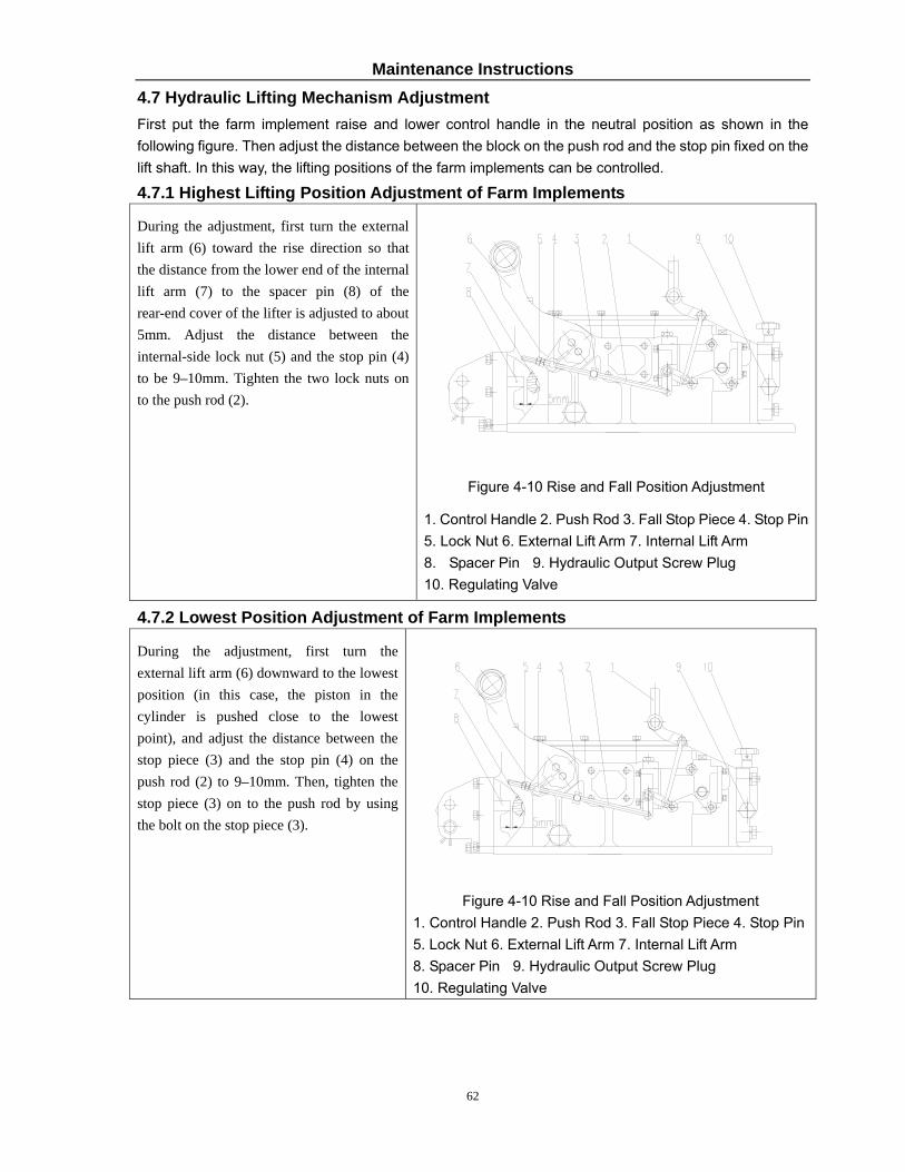
Maintenance Instructions
62
4.7 Hydraulic Lifting Mechanism Adjustment First put the farm implement raise and lower control handle in the neutral position as shown in the following figure. Then adjust the distance between the block on the push rod and the stop pin fixed on the lift shaft. In this way, the lifting positions of the farm implements can be controlled.
4.7.1 Highest Lifting Position Adjustment of Farm Implements
During the adjustment, first turn the external lift arm (6) toward the rise direction so that the distance from the lower end of the internal lift arm (7) to the spacer pin (8) of the rear-end cover of the lifter is adjusted to about 5mm. Adjust the distance between the internal-side lock nut (5) and the stop pin (4) to be 9–10mm. Tighten the two lock nuts on to the push rod (2).
Figure 4-10 Rise and Fall Position Adjustment
1. Control Handle 2. Push Rod 3. Fall Stop Piece 4. Stop Pin 5. Lock Nut 6. External Lift Arm 7. Internal Lift Arm 8. Spacer Pin 9. Hydraulic Output Screw Plug 10. Regulating Valve
4.7.2 Lowest Position Adjustment of Farm Implements
During the adjustment, first turn the external lift arm (6) downward to the lowest position (in this case, the piston in the cylinder is pushed close to the lowest point), and adjust the distance between the stop piece (3) and the stop pin (4) on the push rod (2) to 9–10mm. Then, tighten the stop piece (3) on to the push rod by using the bolt on the stop piece (3).
Figure 4-10 Rise and Fall Position Adjustment 1. Control Handle 2. Push Rod 3. Fall Stop Piece 4. Stop Pin 5. Lock Nut 6. External Lift Arm 7. Internal Lift Arm 8. Spacer Pin 9. Hydraulic Output Screw Plug 10. Regulating Valve
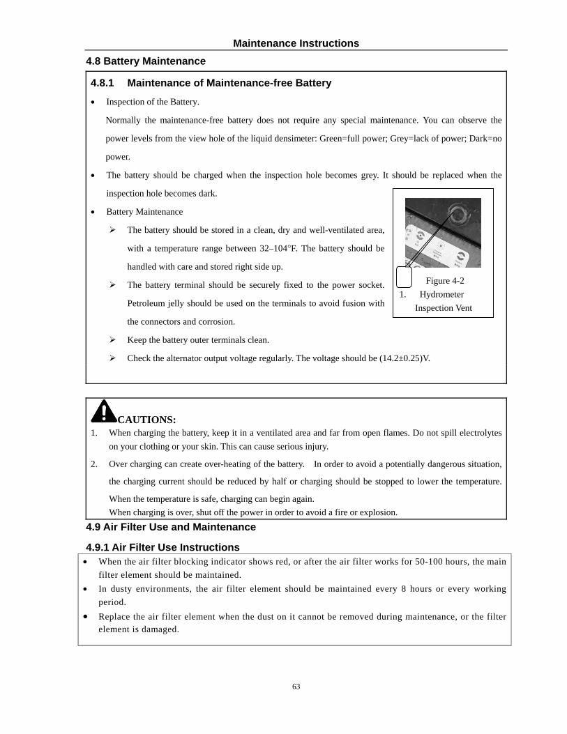
Maintenance Instructions
63
4.8 Battery Maintenance
4.8.1 Maintenance of Maintenance-free Battery
• Inspection of the Battery.
Normally the maintenance-free battery does not require any special maintenance. You can observe the
power levels from the view hole of the liquid densimeter: Green=full power; Grey=lack of power; Dark=no
power.
• The battery should be charged when the inspection hole becomes grey. It should be replaced when the
inspection hole becomes dark.
• Battery Maintenance
The battery should be stored in a clean, dry and well-ventilated area,
with a temperature range between 32–104°F. The battery should be
handled with care and stored right side up.
The battery terminal should be securely fixed to the power socket.
Petroleum jelly should be used on the terminals to avoid fusion with
the connectors and corrosion.
Keep the battery outer terminals clean.
Check the alternator output voltage regularly. The voltage should be (14.2±0.25)V.
CAUTIONS: 1. When charging the battery, keep it in a ventilated area and far from open flames. Do not spill electrolytes
on your clothing or your skin. This can cause serious injury.
2. Over charging can create over-heating of the battery. In order to avoid a potentially dangerous situation,
the charging current should be reduced by half or charging should be stopped to lower the temperature.
When the temperature is safe, charging can begin again. When charging is over, shut off the power in order to avoid a fire or explosion.
4.9 Air Filter Use and Maintenance
4.9.1 Air Filter Use Instructions • When the air filter blocking indicator shows red, or after the air filter works for 50-100 hours, the main
filter element should be maintained. • In dusty environments, the air filter element should be maintained every 8 hours or every working
period. • Replace the air filter element when the dust on it cannot be removed during maintenance, or the filter
element is damaged.
Figure 4-2 1. Hydrometer
Inspection Vent

Maintenance Instructions
64
4.9.2 Air Filter Maintenance • Take out the air filter element. Use a brush to clean the inner case of the air filter and remove the dust
from the rubber dust bag. • Turn the filter element, and use compressed air of less than 500KPa (72.5 psi) to blow the dust from
the inside of the filter element. • Re-install the air filter element.
4.10 Fan Belt Tensioning Adjustment
Press down on the middle part of the fan belt with your thumb. The exerted force should be 29.4–49.0N (6.6 – 11lb), and the deflection should be 15±3mm (0.6–0.7 in). If this requirement is not met, the belt tension should be adjusted accordingly. The adjustment method is as follows:
Loosen the lock nut on the alternator support arm. Pivot the alternator outwards to tension the belt, and then tighten the lock nut on the alternator support arm.
Figure 4-11 Fan Belt Tensioning Adjustment
IMPORTANT ITEMS: Correct use and maintenance of the air filter directly relates to the service life of the engine. Therefore, the air filter should always be kept clean. When the tractor is used on a farm, the air filter should be checked and cleaned after each working period.

Maintenance Instructions
65
4.11 Engine Oil Maintenance and Changing the Oil
(1)Raise the tractor hood and remove the oil dipstick (A) in top right of the engine, and check whether the oil level is between the upper scale mark and the lower scale mark. If the oil level does not reach the lower scale mark, oil should be added until the oil level reaches the recommended level.
Figure 4-12 Check the Engine Oil Level
(2)Before maintenance and replacement of the oil , preheat the engine. After the oil temperature reaches 50–60°C (122-140°F), remove the oil drain plug (A) under the oil pan, drain out the dirty oil, replace the plug, and add new oil. Clean the outside of the oil pan afterwards.
Figure 4-13 Engine Oil Drain Plug
NOTE: Filter locations are described from the point of view of an operator sitting in the driver’s seat.
IMPORTANT ISSUES: Never mix new and old engine oil or blend different brands of oil, as this can
damage the engine. Replace the engine oil strictly in accordance with the time limits recommended in the
Operation Instruction of the Diesel Engine manual.

Maintenance Instructions
66
4.12 Fuel Filter Maintenance
4.13 Engine Oil Filter Maintenance
The engine oil filter (A) is located under the bottom center on the left side of the engine. It should be replaced after every 200 working hours. When replacing the oil filter also change the engine oil. For detailed maintenance procedures, refer to the engine manufacturer’s Operation Manual.
Figure 4-15 Engine Oil Filter Maintenance
4.14 Hydraulic Oil Filter Maintenance
The hydraulic oil filter (A) is located under the starter motor on the lower right side of the engine. The cleaning method is as follows. Place a drip pan under the filter, then loosen and remove the end cover. Remove the hydraulic oil filter element and use solvent to clean it, then use compressed air to blow it dry. Replace the filter element when cleaning it becomes difficult or it is damaged.
A
Figure 4-16 Hydraulic Oil Filter Maintenance
The diesel fuel filter is located on the top left of the engine. Open the tractor hood to access it. Never wash the paper filter element of the filter. The fuel filter element should be replaced after every 200 working hours. For detailed maintenance procedures, refer to the engine manufacturer’s Operation Manual.
Figure 4-14 Fuel Filter Maintenance

Maintenance Instructions
67
4.15 Front Drive Oil Level Maintenance
When checking the front drive oil level, the oil dipstick (A) should be unscrewed and the oil level should fall within the scale range on the dipstick, Otherwise, oil needs to be added. The left and right final drives also have fill ports where the oil level can be checked.
When replacing the front drive oil, unscrew the main drive drain plug (B) and the final drive drain plugs on the left and right (not shown). Discharge all of the dirty oil, retighten the plugs and add new oil at (A) to the “Full” mark on the dipstick. Also add new oil to the left and right final drives through their respective fill ports at the top of each drive.
Figure 4-17 Front Drive Oil Level Maintenance
4.16 Transmission Oil Level Maintenance
Remove the oil dipstick (3), which is located at the right-back side of the transmission box (as shown in Figure 4-18). Wipe it, and then reinsert the oil dipstick. If the oil level does not reach the lower scale mark of the oil dipstick when pulled back out, transmission oil should be added so that the oil level is located between the upper and lower scale marks of the dipstick. A new measurement should be taken 5 minutes after the oil is added. To replace the lubricating oil, remove the oil drain plug from the bottom of the transmission box to drain out the dirty oil into a drip pan. Then, tighten the oil drain plug and add new oil.
Figure 4-18 Transmission System Maintenance
1. Refill Opening 2. Refill Opening Cap 3. Oil Dipstick 4. Oil Dipstick Bracket
NOTE: When checking the oil level, the tractor should be parked on level ground, and the engine should be shut down.

Maintenance Instructions
68
4.17 Lifter Maintenance
• Unscrew the oil dipstick (A) on the hydraulic auxiliary tank located above the lifter (as shown in Figure 4-19). If the oil level does not reach the lower scale mark, oil should be added.
• To replace the lubricating oil, unscrew the oil drain plug (C) located under the lifter. Drain out the dirty oil into a drip pan. Then, reinstall the plug, and add new oil through the refill opening (B).
A C B
Figure 4-19 Lifter Maintenance
NOTE: Park the tractor on level ground, lower the lift arm to the lowest position and shut down the engine before checking the oil level.
4.18 Fuel Tank Maintenance
Park the tractor on level ground, shut down the engine and remove the fuel drain plug located under the fuel tank to drain out the deposits from the bottom of the fuel tank. Use a drip pan and dispose of the used fuel properly. Reinstall the fuel drain plug and fill the fuel tank with fresh diesel fuel.
4.19 Tire Inflation
Use a pressure gauge to measure the pressure in the tires. For details about the inflation pressure of the tires, refer to the List of Technical Specifications for 35XT Series Tractors.
NOTE: Excessively low or high tire pressure will shorten the service life of the tires. It will affect steering and control of the tractor, and could lead to hazardous situations.

Maintenance Instructions
69
4.20 Engine Cooling System Maintenance
The engine cooling system uses a 50/50 water/antifreeze blend. In general the antifreeze is good for a period of 2 years or 1,600 hours. After that the coolant should be replaced. The cooling system should be flushed out before new coolant is added. Use clean water for the flushing process.
Close the radiator drain valve, add a 50/50 water/antifreeze mixture and run the engine for 20 minutes. Then shut off the engine, let it cool down, and check for leaks and for the correct coolant level
Figure 4-20 Cooling System Maintenance
4.21 Bleeding the Fuel System
• If the tractor is not used for a long time, or when the diesel filter element is replaced, or the fuel tank is kept empty, air could enter the fuel line, making it difficult to start the engine. This problem can be fixed by following the steps below but first the fuel tank should be filled and the fuel cutoff switch turned on.
• Unscrew the bleeder screw (A) on the fuel filter, and then move the fuel supply pump draw knob (C) up and down until there are no air bubbles in the diesel fuel flowing out from the bleeder screw.
• Tighten the fuel filter bleeder screw (A), and unscrew the air bleed screw (B) on the fuel injection pump. Pump the fuel supply hand primer knob (B) until the there are no air bubbles in the diesel fuel flowing out of the bleeder screw. Then tighten the fuel filter bleeder screw (C).
Figure 4-24 Exhaust of Fuel System
IMPORTANT ISSUES: The engine runs on high quality light diesel oil and must meet specifications. Generally, 2 light diesel oil should be used in summer, and 1 light diesel oil should be used in winter.
IMPORTANT ISSUES: During winter, water in the radiator can freeze, causing the engine block to crack. Always use antifreeze in the radiator.

Storage
70
5 Storage When the tractor is going to be out of use for an extended period of time (more than one month) it should be kept in a proper storage building. The storage facility should provide protection from the elements so as to keep the tractor clean and prevent rust and corrosion. Before storing the tractor it must undergo a thorough cleaning and adjustment and tightening of various parts, subject to the technical maintenance requirements based on the duty hours, so that the tractor remains in good technical condition.
IMPORTANT ISSUES: During long periods of non-use it is very important to preserve and maintain the
tractor. If special steps are not taken, the life of the tractor could be shortened and parts could deteriorate..
5.1 Tractor Storage—Causes of Damage • Rust: During the storage period, dust and moisture in the air get into the tractor. This can cause
contamination and rusting of the components. When pistons, valves, bearings and gears stay in one place for an extended period of time, they lose lubricant film protection, which produces rust and causes parts to stick and seize up.
• Aging: Some components are made of with rubber and plastic parts, which will age and deteriorate, getting brittle and rotting, under the ultraviolet rays in sunlight.
• Deformation: Components such as drive belts and tires may become distorted in shape if left in the same place for too long.
• Others: Electrical parts are affected by damp conditions, and the battery can discharge over time.
5.2 Tractor Storage • Prior to storage inspect the tractor and its surroundings to ensure that the tractor can be stored safely.
The external surface of the tractor should be cleaned. • Remove the battery, coat the terminals posts with petroleum jelly, and keep it in dark,
well-ventilated room with a consistent moderate temperature. • Drain the engine oil while it is hot and fill with fresh engine oil. Run the engine for 10 minutes at
idle to allow the new engine oil to adhere to the surfaces of all the moving parts evenly. • Add lubricant to all the various lubrication points. • Coat the electrical contacts, connectors and all unpainted metal part surfaces with anti-corrosion
spray. • Loosen the fan belt on the engine and remove it if necessary. Wrap the belt(s) securely and spray the
pulley groove with a rust-proof agent. If possible, paint over all chips in the paint and cover non-painted metal parts with a preservative.
• Drain diesel fuel from the fuel tank or add diesel fuel conditioner to the fuel tank. • Seal any engine opening such as intakes/outlets with protective material to prevent foreign matter,
dust, and moisture from getting in. • Place all control handles in the neutral position (including electrical system switches and the parking
brake). • If possible, prop the tractor on blocks so that the tires are free of weight. Check the tire pressure on a
regular basis. • The tractor should be parked in a dry, well ventilated area. If such an area is unavailable, cover the
tractor with a waterproof covering. Never store the tractor around flammables or corrosive materials. • Any parts removed from the tractor should be cleaned, packed and stored in a dry place.

Storage
71
5.3 Tractor Storage Maintenance
• Check on the tractor and its parts at least once a month to see whether there is any rust, corrosion,
aging and distortion happenings
• Start the tractor bi-monthly and allow the engine to run. This will prevent interior rust.
• If possible, drive the tractor once every three months at low speed for 20 to 30 minutes. This is a great
way to see how the tractor is fairing in storage.
• Clean dust off the top of the battery with dry cloth, and check the charge level. The battery can go dead
even when not in use. Recharge the battery once a month.
• When transporting long distances by train, truck, or trailer the gears should not be engaged. Transporting
the tractor with the gears engaged, will drive the parts such as the gears, bearings, crankshaft and
pistons, which can rub without lubricant and cause damage.
IMPORTANT ISSUES: If you cannot carry out the anti-rust treatment and the tractor needs to be out of use for several months or longer, at a minimum, replace the machine oil and oil filter. Start the tractor once every month and run the tractor at low speed for 20–23 minutes at a minimum. Check to make sure everything is operating properly and keep the tractor clean and try to limit the amount of corrosion that could result from dust and wet conditions.
5.4 Removing Tractor from Storage • Remove the grease used for anti-rusting • Reopen the various sealed up nozzles and clean the tractor • Check coolant, machine oil, and diesel fuel and lubricate all of the lubrication points according to
the provisions. • Remove any anti-rust agent in the belt grooves and reinstalls and/or adjust the belts. (See: Engine
Instruction for Use and Maintenance) • Reinstall the battery and check the terminals. • Check that all of the circuits, hoses and lines are properly connected. • Check air pressure in tires.
NOTE: Please refer to the “Engine Instruction for Use and Maintenance” for details on engine storage and
removing tractor from storage.
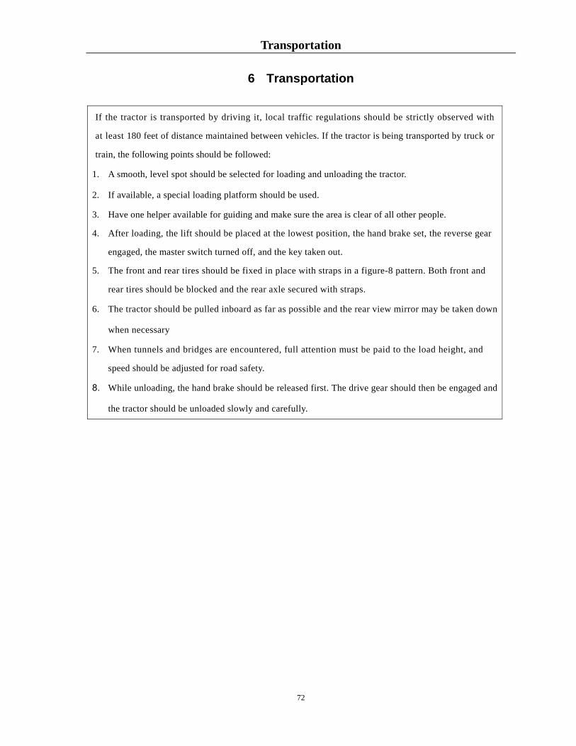
Transportation
72
6 Transportation
If the tractor is transported by driving it, local traffic regulations should be strictly observed with
at least 180 feet of distance maintained between vehicles. If the tractor is being transported by truck or
train, the following points should be followed:
1. A smooth, level spot should be selected for loading and unloading the tractor.
2. If available, a special loading platform should be used.
3. Have one helper available for guiding and make sure the area is clear of all other people.
4. After loading, the lift should be placed at the lowest position, the hand brake set, the reverse gear
engaged, the master switch turned off, and the key taken out.
5. The front and rear tires should be fixed in place with straps in a figure-8 pattern. Both front and
rear tires should be blocked and the rear axle secured with straps.
6. The tractor should be pulled inboard as far as possible and the rear view mirror may be taken down
when necessary
7. When tunnels and bridges are encountered, full attention must be paid to the load height, and
speed should be adjusted for road safety.
8. While unloading, the hand brake should be released first. The drive gear should then be engaged and
the tractor should be unloaded slowly and carefully.

Technical Specifications for 35XT Series Tractors
73
7. Technical Specifications
7.1 Main Technical Specifications for 30XT Series Tractors
Table 7-1 Main Technical Specifications for NorTrac 35XT Series Tractors
Model Unit 35XT
Type —— 4×4 Wheeled
Rated Traction Force kN 7.6
Maximum Power of the Power Take Off (PTO) Shaft
kW 21.88
Length (from Counterweight to Hanging)
3,500
Width 1,555 Boundary Dimension Height (to
Safety Shelf/Driving Cab)
2,675/2,400
Axle Base 1,806
Front Wheel 1,220 Wheel Span
Rear Wheel 1,240~1,440 Minimum Ground Clearance 320 (Front Axle Oil Drain Plug) Ground
Clearance Agricultural Clearance
mm
365 (Lower Plane of Rear Axle Housing)
In the Case of One-side Braking 2.9±0.2
Minimum Track Circle
Radius In Case One-side
Braking Is Not Used
m
3.35±0.3
Structural Mass 1,435 Minimum Mass in Use 1,600
Front Wheel 700 Mass Distribution Rear Wheel 900
Front Counterweight
80 Counterweight
Option Rear Counterweight
kg
124
Model —— 4L22TA Type —— Vertical, Water-cooled and Four-stroke Diesel Engine
Engine
Number of Cylinders
—— 4

Technical Specifications for 35XT Series Tractors
74
Model Unit 35XT
Cylinder Diameter × Stroke
mm 85×95
Nominal Power kW 25.7 Nominal Speed r/min 2,350 Maximum Torque/ Rotational Speed
N·m/rpm
≥124/1,650±100
Specific Fuel Consumption in Rated Conditions
≤248
Engine Oil Consumption in Rated Conditions
(g/kW h)
≤2.04
Lubrication Method
—— Pressure Type
Starting Method —— Electrical Starting Gear Number —— 8+8
Rear Driving Wheel Specifications —— 12.4-24 1 2.14 2 2.97 3 4.77
Low
4 6.47 1 9.72 2 13.50 3 21.37
Forward
Gear
High
4 29.00 1 1.99 2 2.76 3 4.44
Low
4 6.02 1 9.05 2 12.57 3 19.9
Shuttle-type Gear
Reverse
Gear
High
4
27
Clutch —— Dual-Disk, Dry Type, Disk Spring Compacting, Constant Engaged and Non-Independent Double-Acting Clutch
Gear Box —— Dual-shaft constituting Mechanical Gear Box, 8F+8R Shuttle-Type Gear (8 forward gears and 8 reverse gears), Shifting Slide Gear Shift
Transmissio
n Syste
m Rear Central Drive —— Spiral Bevel Gear Type

Technical Specifications for 35XT Series Tractors
75
Model Unit 35XT
Differential Mechanism
—— Closed Type, 2 Bevel Planet Gears
Differential Lock —— Teeth Embedding Type
Axle
Rear Final Drive —— Built-in Type, Single Straight Spur Gear Rack —— Half Rack Type
Front Wheel 200~250 Tire Pressure
Rear Wheel kPa
110~140
Front Wheel —— 7.5-16
Running
System
Tire Specifications
Rear Wheel —— 12.4-24
Method —— Front-Wheel Steering (Front-Wheel Toe-In 0–4mm) Steering
System
Steering Gear —— Cycloid Rotary Valve Type Full Hydraulic Steering Gear
Service Braking —— Horseshoe Type Brake Parking Brake —— Horseshoe Type Braking
Braking
System
Trailer Braking Maneuver ——
Air Brake
Hydraulic System Type —— Open-Center Type, Remote Type Hydraulic Oil Pump —— CBJ30-F12 Distributor —— Slide Valve Type
Diameter × Stroke
mm 85×105 Oil Cylinder
Form Single-acting
Hitch mm
Rear Mounted Three-point Linkage, Category 0, Category I Upper Suspension Point, Attachment Hole × Width:
φ19.3×44 Lower Suspension Point, Attachment Hole × Width:
φ22.4×35 Tilling Depth Adjusting Method
—— Position and Floating Control
Maximum Lifting Power (610mm Behind the Lower Suspension Point)
kN 5.79
Opening Pressure of the System Safety Valve
MPa 17.5~18.0
Form —— Rear-Set Type
Working
Devices
Hydraulic Output Quantit
y ——
Single Hydraulic Output (Select Two-Way Valve)

Technical Specifications for 35XT Series Tractors
76
Model Unit 35XT
Specification
—— M22×1.5 or NPT1/2
Form —— Non-Independent Type
Specification —— φ35, 6 Tooth Rectangle Spline Shaft (φ35, 8 tooth rectangle
spline shaft may be selected)
Power Take Off
Shaft Rotational Speed r/min 540/1,000
Form —— Swing-Rod Type Traction Apparatus
Height from the Ground
mm 305
Traction and Trailer Devices Trailer Apparatus —— U-Shaped Hook Hitch
Driving Cab (Optional) —— Seal the Driving Cab (Select the Warm Wind)
Safety Shelf —— 2-Column Type
Driver Seat —— Mechanical Floating Type, PVC Surface Layer (the front
and back and backrest are adjustable) Electrical System —— 12V Negative Double Bond Strap
Model —— / Voltage V 14 Alternator
Power kW 0.35 Model —— 6-QW-90 Voltage V 12 Capacity A·h 90
Battery
Quantity —— 1 Head Lamp —— 12V, 55/60W, Combined Type Front Steering Lamp
—— 12V, 21W, 2 (in quantity)
Rear Combination Lamp
—— 12V, 21W Brake Lamp, 5W Rear Position Lamp and 21W
Steering Lamp (all in sets of 2)
Rear Working Light
—— 12V, 28W, 1 (in quantity)
Lighting and
Signaling Device
Trailer Socket
—— 7-hole Trailer Socket, 1 (in quantity)
Instrument ——
Combination Instrument: Ammeter, Fuel Gauge, Water Temperature Gauge, Oil Pressure Gauge, Air-Pressure Alarm and Timer, etc.
Electric Instrument System
Monitoring and
Warning Devices
Warning Device ——
Signal Lamp and Device: Brake Light, Left and Right Steering Lamps, Front and Rear Position Lights, Reflector and Safety Warning Sign

Technical Specifications for 35XT Series Tractors
77
Model Unit 35XT
Radiator 10 Fuel Tank 32 Engine Oil Pan 6 Oil Used in Transmission Box
20
Oil Used in Lifter 11
Filling Capacity
Oil Used in Front Drive Axle
L
6

Disassembly and Disposal
78
8. Disassembly and Disposal
After the machine reaches the end of its service life, for your personal safety and the protection of the
environment, please deliver it to the licensed company specialized in the disassembly and recycle of such
products.
When ready for scrapping, the tractor should be disassembled in a sequence, from top to bottom, outside
to inside. In case of large objects or heavy mass, a special hoisting mechanism should be used. Please
take the battery to a battery recycling company and collect all waste oil for proper treatment.
WARNING: The battery electrolyte is corrosive. Take precautions to ensure that it does not get in
your eyes or on your skin or clothes. If this were to happen, clean the affected area immediately with water and
seek medical treatment as soon as possible.
ATTENTION: Battery acid and machine oil are contaminants. Contaminants should be disposed of
properly following local laws so as not to cause any damage to the environment.
Breaking down a retired tractor requires special tools and practical experience. A lack of either of these can
add up to serious injury to damage to the environment.
WARNING: When disassembling large or heavy objects (i.e., a tractor) a special hoisting mechanism
must be used and care should be taken to ensure safety at all times.

Limited Warranty
79
LIMITED WARRANTY
4WD Diesel Tractor & Compact Crawler / Bulldozer
NorTrac™ equipment is sold by NorTrac; a division of Northern Tool & Equipment Company, Inc. NorTrac will repair or replace, at its option, any part(s) thereof of the NorTrac™ 4WD diesel tractor or compact crawler / bulldozer that are shown to be defective in material and/or workmanship, under normal use during the applicable warranty period. There is a $100.00 deductible on the labor per warranty repair. After the labor deductible, all warranty repairs and replacements will be made without charge for parts or labor at a pre-authorized service center. All parts replaced as a result of this limited warranty become the property of NorTrac and must be returned upon request. All parts replaced will become a portion of the whole and will be warranted for the duration of the original equipment warranty.
Length of Warranty The limited warranty begins on the original date of purchase and extends to 24 months for consumer household use. For the commercial end user, the limited warranty continues for thirty (30) days (Commercial use is defined as all applications in which the equipment is used for income production purposes, business purposes, or used by any governmental agency).
To qualify for the limited warranty you must: • Be the original purchaser of the equipment. The limited warranty is non-transferable. • Provide proof of purchase. • Have purchased the equipment in the United States from authorized representatives of NorTrac and/or
Northern Tool & Equipment Company, Inc.
To obtain service you must: Contact NorTrac’s Warranty Administrator by calling 1-952-641-2592 to relay your concerns about the equipment and to receive authorization from the Warranty Administrator. Or mail a letter with detailed failure and contact information to the address listed at the bottom of this page. After receiving authorization from NorTrac’s Warranty Administrator and the address of the Preauthorized Service center, take the equipment to the service center during their regular business hours. Transportation costs are the responsibility of the equipment owner. If you are not able to secure warranty service from the authorized service center or are not happy with the service, please contact NorTrac’s Warranty Administrator by calling 1-952-641-2592.
Exclusions and Warranty Disclaimers: This limited warranty applies to equipment used in its original form. Any unauthorized modifications or any incorporation or use of unsuitable attachments or parts will automatically void this limited warranty. This limited warranty does not include parts affected or damaged by accident and/or collision, normal wear & tear (battery, belts, tires, clutch, etc.), fuel contamination, or from failure to follow the instructions contained in the User Manual for the equipment. The cost of normal maintenance of the equipment is the responsibility of the owner.

Limited Warranty
80
This limited warranty does not extend to use in applications for which the equipment was not designed or to damages resulting from misuse, abuse, or neglect. Disclaimer of Consequential Damage: Any implied warranty of merchantability or fitness for a particular purpose, to the extent that either may apply to any NorTrac™ tractor or compact crawler / bulldozer, shall be limited in duration to the periods of the express warranties shown above, and to the extent permitted by law any and all implied warranties are excluded. In no event will NorTrac or Northern Tool & Equipment Company, Inc. be liable for any loss of income, loss of time or use of the product, transportation, hiring of alternative services, commercial loss or any other incidental, consequential, or special damages and / or expenses. Some states do not allow limitations on how long an implied warranty lasts and / or do not allow the exclusion or limitation of incidental or consequential damages, so the above exclusions and limitations may not apply to you. This limited warranty gives you specific legal rights which may vary from state to state.
NorTrac C.O Warranty Administrator - Warranty Information 2800 Southcross Drive West — PO Box 1219 Burnsville, MN 55337

Appendices
81
10 Appendices 10.1 Tractor Fuel, Oils and Solutions
Table 10-1 Tractor Fuel, Oils and Solutions
Application Locations of Oils and Solutions
Fuel, Oils and Solutions
Fuel Tank International
standard
Adopt ASTM D-975 fuel. Under general air temperatures, use 2-D grade fuel; when ambient temperatures are below 32 F, use 1-D grade fuel.
Engine Sump International
standard
Engine sump, injection pump, and governor use viscosity grades compliant with SAE viscosity classifications. Use all-season SAE 15W/40 multi-grade oil. Quality class should comply with API CD grade standard.
Water radiator Use a 50/50 blend of antifreeze and water.
Gearbox-rear
axle, hydraulic
lifter, and front
drive axle
International
standard
Drive system and lifter, hydraulic steering, and central and final drives
of front drive axle can use MF1135 (Massey Ferguson), M2C 86A
(Ford), or J20A (John Deer) general-purpose oil.
Steering fluid International
standard
Same as above.
Oil Fittings/
grease zerks
International
standard
Use a multipurpose grease.
Battery Maintenance free
IMPORTANT ISSUES: Mixing oils of different brands and manufacturers can affect the service performance of the machine. Use
of mixed oils for engine or drive lubrication or the hydraulic system is not recommended.
WARNINGS: 1. To avoid danger, do not refill the fuel tank while operating the diesel engine.
2. If the tractor is working under severe sunlight the fuel tank should not be completely filled, as this will cause
an overflow due to fuel expansion. If fuel overflows, it should be wiped up immediately.
IMPORTANT ISSUES: The cooling system should use a 50/50 water/antifreeze mix in all seasons.

Appendices
82
10.2 Main Bolts, Screws and Nuts Tightening Torque
Table 10-2 Main Bolts, Screws, and Nuts Tightening Torque Table
Name and Assembly Position Thread
Specification
Tightening
Torque [N·m]
Tightening
Torque [LB FT]
The bolt and nut connecting the engine and the
clutch housing. M10 41~51 30~37
The bolt connecting the clutch housing and the
rear axle casing. M14X1.5 123~154 90~113
The bolt securing the bearing block of the primary
shaft and the secondary shaft. M10 41~51 30~37
The bolt securing the interlocking wedge. M10 50~70 36~51
The bolt connecting the slave drive spiral bevel
gear. M10X1.25 45~55 33~40
The bolts connecting the drive shaft shell and the
rear axle housing. M12×1.5 73~89 53~65
The bolt connecting the driving wheel hub and the
radial plate. M18×1.5 397~457 293~337
The lock nut that locks the front shaft cross bar. M16X1.5 122~149 90~110
The bolt connecting the subassembly of the front
outer shaft and the front inner shaft. M14 122~149 90~110
The bolt connecting the front driving wheel, the
front wheel hub and the radial plate. M14×1.5 178~218 131~160
The bolt connecting the front axle and the bracket. M16 182~222 134~164
The bolt connecting the front bracket and the
battery tray. M12 73~89 53~65
The bolt connecting the bracket and the engine. M12 73~89 53~65
The bolt connecting the bracket and the engine. M14X1.5 126~154 93~114
The bolt connecting the lifter shell and the rear
axle housing. M10 41~51 30~37
The bolt connecting the steering gear and the
clutch housing. M14 122~149 90~110
The coupling bolt for the limited rod support. M14 122~149 90~110

Appendices
83
WARNING: When tightening the major bolts and nuts on the tractor, torque wrenches should be used to avoid a reduction in machine performance and personal injury, which is caused by a failure to meet the requirements for the tightening torques.
10.3 Tractor Bearings
Table 10-3 Detailed List of Tractor Bearings
No. Code Bearing
Code Bearing Name Assembly Position Quantity
1 GB/T 276 6203-Z Ball Bearing Front of the Clutch Shaft 1
2 GB/T 276 6006 Ball Bearing Front of the Power Take
Off Drive Shaft 1
3 GB/T 276 6206 Ball Bearing Front of the Output Shaft
of the Transfer Case 1
Rear of the Power Take
Off Shaft 1
4 GB/T 276 6207 Ball Bearing Driving Gear of the
Intermediate Drive 2
Reduction Driving Gear at
the End of the Front Drive
Axle
2
5 GB/T 276 6208 Ball Bearing Driven Gear of the
Intermediate Drive of the
Front Drive Axle
2
6 GB/T 276 6210 Ball Bearing Outer End of the Drive
Shaft 2
7 GB/T 276 6211 Ball Bearing Inner End of the Drive
Shaft 2
8 GB/T 276 6305 Ball Bearing Rear of the Power Take
Off Drive Shaft 1
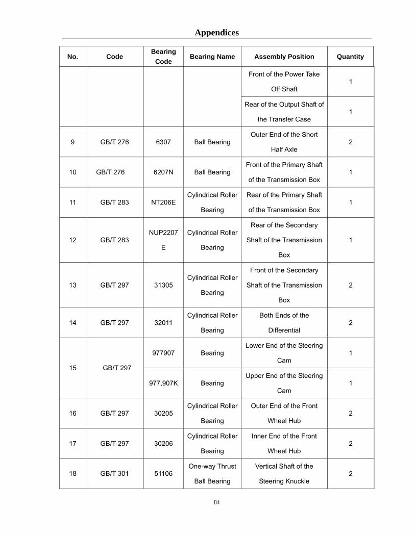
Appendices
84
No. Code Bearing
Code Bearing Name Assembly Position Quantity
Front of the Power Take
Off Shaft 1
Rear of the Output Shaft of
the Transfer Case 1
9 GB/T 276 6307 Ball Bearing Outer End of the Short
Half Axle 2
10 GB/T 276 6207N Ball Bearing Front of the Primary Shaft
of the Transmission Box 1
11 GB/T 283 NT206E Cylindrical Roller
Bearing
Rear of the Primary Shaft
of the Transmission Box 1
12 GB/T 283 NUP2207
E
Cylindrical Roller
Bearing
Rear of the Secondary
Shaft of the Transmission
Box
1
13 GB/T 297 31305 Cylindrical Roller
Bearing
Front of the Secondary
Shaft of the Transmission
Box
2
14 GB/T 297 32011 Cylindrical Roller
Bearing
Both Ends of the
Differential 2
977907 Bearing Lower End of the Steering
Cam 1
15 GB/T 297
977,907K Bearing Upper End of the Steering
Cam 1
16 GB/T 297 30205 Cylindrical Roller
Bearing
Outer End of the Front
Wheel Hub 2
17 GB/T 297 30206 Cylindrical Roller
Bearing
Inner End of the Front
Wheel Hub 2
18 GB/T 301 51106 One-way Thrust
Ball Bearing
Vertical Shaft of the
Steering Knuckle 2

Appendices
85
No. Code Bearing
Code Bearing Name Assembly Position Quantity
Lower End of the Front
Final Drive Shell 2
19 688711 Release Bearing Release Bearing of the
Clutch 1
20 GB/T 5,846 K202,417 Needle Bearing Intermediate Shaft of the
Transfer Case 2
21 GB/T 5,846 K25,3120 Needle Bearing Output Shaft of the
Transfer Case 2
22 GB/T 5,846 K283,327 Needle Bearing Driven Gear of Gear 2
23 GB/T 5,846 K303,527 Needle Bearing H-L Stationary Gear 2
24 GB/T 292 7,206AC Angular Contact
Ball Bearing
Inner End of the Front
Drive Shaft 2
25 GB/T 292 7,208AC Angular Contact
Ball Bearing
Outer End of the Front
Drive Shaft 2
26 GB/T 297 32007 Cylindrical Roller
Bearing
Middle of the Mater Pinion
Shaft 1
27 GB/T 297 32010 Cylindrical Roller
Bearing
Front Axle Differential
Shell 2
28 GB/T 297 32207 Cylindrical Roller
Bearing
Front of the Mater Pinion
Shaft 1
Driving Gear of Gearbox 1 29 GB/T 5,846 K424,822 Needle Bearing
Driving Gear of Gearbox 1

Appendices
86
10.4 Seals on the Tractor Chassis:
Table 10-4 Detailed List of Tractor Chassis Seals
Component Specification Assembly Position Qty.
B35×55×8 Front of the Primary Shaft 2
FB35×55×8 Inside of the Bearing Cover
of the Power Take Off Shaft 2
B50×72×8 Outside of the Drive Shaft 6
GB/T 9877.1
Rotary Shaft Lip
Seal
B55×75×8 Inside of the Drive Shaft 4
JB/T2600
Oil Seal PD50×80×12
Driving Gear Shaft of the
Final Drive 2
11.8×1.8G Shifting Fork Shaft of the
Power Take Off 1
15×2.65G Shifting Fork Shaft of the
Differential Lock 1
22.4×2.65G Reverse Shaft 1
28×3.55G Driving Gear Shaft of the
Final Drive 2
67×3.55G Front Bearing Block of the
Secondary Shaft 1
103×3.55G Bearing Block of the Rear
Axle 2
Transmission
Box
GB/T3452.1
O-Ring
112×3.55G Drive Shaft Sleeve 2
Brake GB/T3,452.1
O-Ring 15×2.65G Brake Camshaft 2
Vertical Axle Oil Seal
38×74×11.5
Lower End of the Steering
Knuckle 2 Front Shaft Non-Standard
(Shown in the
Drawing) Half Axle Oil Seal
38×74×11.5 Front Wheel Hub 2

Appendices
87
Component Specification Assembly Position Qty.
Upper End of the Left and
Right Steering Knuckle 2
GB/T3,452.1
O-Ring 30×3.55G
Both Ends of the Rocker
Shaft 2
Steering
Gear
GB/T9,877.1
Rotary Shaft Lip
Seal
B30×45×8 Steering Pitman Arm Shaft 1
JB/T2,600
Oil Seal PD42×62×10 Lift Shaft 2
10×13.5 Oil Drain Plug 1
10×13.5 Cylinder Head 2
18×22 Position of the Hydraulic
Output Hollow Bolt 1
JB/T 982
Seal
36×42 Fuel Filling Breather
Assembly 1
71×2.65G Cylinder Sleeve and
Housing Seal 1
17×2.65G Cylinder Head Adjusting
Valve 1
53×5.3G Piston and Oil Cylinder 1
Lifter
GB/T3,452.1
O-Ring
53×5.3G Piston and Oil Cylinder 1
Handle Shaft, Safety Valve
Seat 1
9×2.65G Junction Surface of the Lifter
Shell 1
13.2×2.65G Impaction Screw Plunger of
the Safety Valve 1
Distributor GB/T3,452.1
O-Ring
15×2.65G Junction Surface of the Lifter 1

Appendices
88
Component Specification Assembly Position Qty.
Shell
19×2.65G Junction Surface of the Lifter
Shell 1
Oil Pump
and Oil
Passage
GB/T3,452.1 18×2.65G
O-Ring 18×2.65G
Suction Area of the Oil
Pump 1
JB/T2,600
Oil Seal SG30×45×8
Output Shaft of the Transfer
Case 1
12.5×1.8G Shifting Fork Shaft of the
Transfer Case 1
36.5×2.65G Front of the Rear Jacket
Welding Parts 2
Transfer
Case GB/T3,452.1
O-Ring
53×2.65G Rear of the Rear Jacket
Welding Parts 1
PG45×65×10 Oil Sealing Retainer 2
SD45×70×10 Front Drive Shaft 2
SD50×70×12 Lower End of the Vertical
Shaft Sleeve 2
JB/T2600
JB/T2,600
Oil Seal
W50×72×7 Lower End of the Vertical
Shaft Sleeve 2
33.5×3.55G Master Pinion Shaft 2
34.5×3.55G Bearing Cover 2
40×3.55G Front Rocker Shaft 2
56×2.65G Dust Control Pipe Bracket 1
67×3.55G Front Rocker Shaft 2
Bearing Cover 2
Front Drive
Axle
GB/T 3452.1
GB/T 3452.1
O-Ring
75×2.65G Outer End of the Half Axle
Sleeve 2

Appendices
89
Component Specification Assembly Position Qty.
80×3.55G Back Support 2
85×3.55G Bearing Block of the Mater
Pinion Shaft 2
170×3.55G Drive Shaft Cover 2
175×3.55G Inner End of the Half Axle
Sleeve 2
ATTENTION: Before using farm implements, operators should carefully read the “Use and Maintenance
Instructions” and understand the structure, performance, operation, and supporting features to avoid damaging the
implements and/or personal injury.
NOTES:
1. Before purchasing farm machines and implements, select a good match with your machine or
consult a reputable dealer. Understand your operational conditions (soil resistance, agricultural
requirements, etc.) of the areas where you will be working and referring to this list.
2. Determine the main technical parameters of the farm machines and implements such as models
according to the operational conditions (soil resistance, agricultural requirements, etc.) of the areas
where you will working and refer to the advisories in order to get the appropriate match. Improper
matching will make the new machinery ineffective and, possibly, dangerous.
3. Working efficiency can depend on the implement, the performance of which may vary with
operational conditions (soil resistance, agricultural requirements, etc.). Therefore, you should
determine working speed and width, etc. and make your purchase accordingly.
Distributed by Northern Tool & Equipment Co., Inc. Burnsville, MN 55306-6936
Made in China

On Line Spare Parts System Fill in http://222.132.52.85:8080/
Choose product Model and Code:
Choose “Guest”
Choose English
Choose “Parts catalogue”

Then you can find the parts catalog and diagram of the tractor:
TE354-L161Q1K TE25 Serials
Then search here
TE354-L161Q1KTE25 Serials
TE25 Serials TE354-L161Q1K