product manual - robot system products
TRANSCRIPT
Product Manual
Manual quick tool changer MQC300 and MQC200
M0622-1
Tool changers | Swivels | Swivels with tool changers | Grippers | Hose packages | Valve Units | Tool systems

2 M0622-1 ver 2.1
M0622-1 ver 2.1 3
The information in this document is subject to change without prior notice and should not be
regarded as an undertaking from Robot System Products AB. Robot System Products AB
assumes no responsibility for errors that may occur in this document.
Robot System Products AB bears no responsibility for damage that is incurred by the use of this
document, or the software or hardware described in this document.
The document, or parts of it, may not be reproduced or copied without prior permission from
Robot System Products AB. It may neither be imparted to a third party, nor otherwise be used
without authorization. Infringement hereof will be subject to action in accordance with the
applicable laws.
Further copies of this document can be obtained from Robot System Products AB at
current prices.
© Robot System Products AB
Robot Systems Products AB
Isolatorvägen 4
SE-721 37 Västerås
Sweden
4 M0622-1 ver 2.1
CONTENTS
1 INTRODUCTION .........................................................................................................5
1.1 Safety ..............................................................................................................................6
1.1.1 General ................................................................................................................................ 6 1.1.2 Explanation of warnings ...................................................................................................... 6
2 TECHNICAL SPECIFICATIONS ................................................................................7
2.1 Description of MQC manual quick tool changers ...........................................................7
2.2 Coordinate System Definition .........................................................................................8
2.3 Robot adaptation plate ....................................................................................................8
2.3.1 Manual quick tool changer MQC300 master. Article no: P6001B ...................................... 9 2.3.2 Manual tool attachment MQC300. Article no: P6002B ..................................................... 10 2.3.3 Manual quick tool changer MQC200 master. Article no: P6003 ....................................... 11 2.3.4 Manual tool attachment MQC200. Article no: P6004 ....................................................... 12 2.3.5 Manual quick tool changer MQC300 master. Article no: P6005 ....................................... 13 2.3.6 Manual tool attachment MQC300. Article no: P6006 ....................................................... 14
3 INSTALLATION .........................................................................................................15
3.1 Tightening torques ....................................................................................................... 15
3.2 Recommended tools for installation ............................................................................ 15
3.3 Mounting of MQC master (P6001B, P6003 and P6005) on robot side ....................... 16
3.4 Mounting of MQC tool attachment (P6002B, P6004 and P6006 ................................ 17
3.5 Mounting of MQC tool attachment on MQC master .................................................... 18
4 MAINTENANCE AND SERVICE ..............................................................................20
4.1 Maintenance ................................................................................................................. 20
4.1.1 Required products ............................................................................................................. 20 4.1.2 Recommended tools for maintenance .............................................................................. 20 4.1.3 Activities and intervals....................................................................................................... 20
4.2 Dismounting of MQC tool attachment from MQC master............................................ 21
4.3 Dismounting of MQC master........................................................................................ 22
5 SPARE PARTS..........................................................................................................23
5.1 Part list for MQC300, P6001B and P6002B ................................................................ 23
5.2 Part list for MQC200, P6003 and P6004 ..................................................................... 24
5.3 Part list for MQC300, P6005 and P6006 ..................................................................... 25
6 DISPOSAL AND RECYCLING .................................................................................26
M0622-1 ver 2.1 5
1 INTRODUCTION
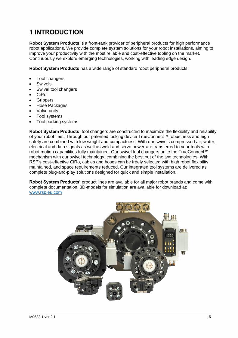
Robot System Products is a front-rank provider of peripheral products for high performance robot applications. We provide complete system solutions for your robot installations, aiming to improve your productivity with the most reliable and cost-effective tooling on the market. Continuously we explore emerging technologies, working with leading edge design.
Robot System Products has a wide range of standard robot peripheral products:
• Tool changers
• Swivels
• Swivel tool changers
• CiRo
• Grippers
• Hose Packages
• Valve units
• Tool systems
• Tool parking systems
Robot System Products’ tool changers are constructed to maximize the flexibility and reliability of your robot fleet. Through our patented locking device TrueConnect™ robustness and high safety are combined with low weight and compactness. With our swivels compressed air, water, electrical and data signals as well as weld and servo power are transferred to your tools with robot motion capabilities fully maintained. Our swivel tool changers unite the TrueConnect™ mechanism with our swivel technology, combining the best out of the two technologies. With RSP’s cost-effective CiRo, cables and hoses can be freely selected with high robot flexibility maintained, and space requirements reduced. Our integrated tool systems are delivered as complete plug-and-play solutions designed for quick and simple installation.
Robot System Products’ product lines are available for all major robot brands and come with complete documentation. 3D-models for simulation are available for download at: www.rsp.eu.com
6 M0622-1 ver 2.1
1.1 Safety
1.1.1 General
The integrator installing the tool changer into the system must follow the safety demands stated in standards and provisions applicable in the country where the tool changer system will be installed. The products are all prepared for CE-certification.
The user of the Robot System Products tool changer is responsible that law and directives applicable in respective countries, with regards to safety, are followed. The user is also responsible to guarantee that all safety devices are installed correctly.
WARNING! Never carry out service work on a robot that has not been taken out of operation. See safety information for the robot.
WARNING! Only perform work on tools attached to the tool changer if the air pressure is safely switched off.
WARNING! Be aware that the tool changer is heavy and may cause personal injury and equipment damage if dropped.
WARNING! Electric signals and power must be disconnected/switched off during dismounting and mounting of tool changer and tools.
1.1.2 Explanation of warnings
The warnings in this document are specific to the products in this manual. It is expected that the user also pay attention to certain notifications from the robot manufacturer and/or the manufacturers of other components used in the installation.
WARNING!
The warning sign will make you aware that a situation could result in potential serious injury or damage to equipment.
NOTE!
The note sign will alert you about something important to consider.
M0622-1 ver 2.1 7
2 TECHNICAL SPECIFICATIONS
2.1 Description of MQC manual quick tool changers
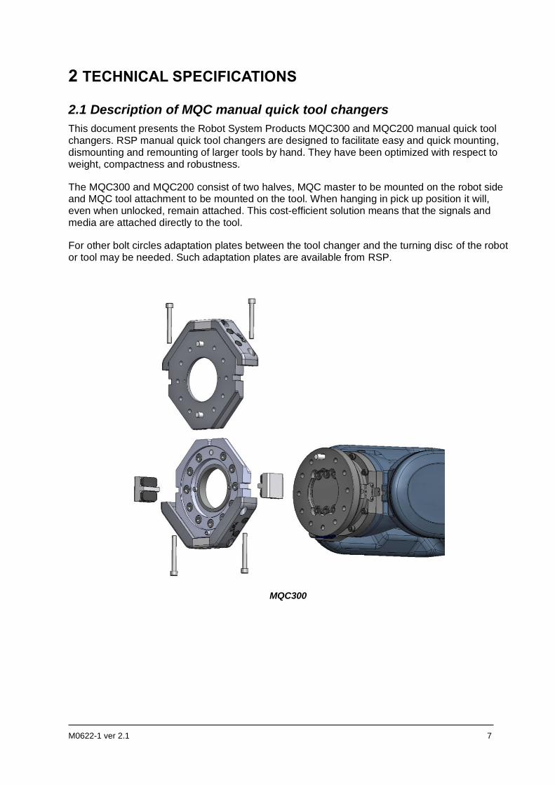
This document presents the Robot System Products MQC300 and MQC200 manual quick tool changers. RSP manual quick tool changers are designed to facilitate easy and quick mounting, dismounting and remounting of larger tools by hand. They have been optimized with respect to weight, compactness and robustness.
The MQC300 and MQC200 consist of two halves, MQC master to be mounted on the robot side and MQC tool attachment to be mounted on the tool. When hanging in pick up position it will, even when unlocked, remain attached. This cost-efficient solution means that the signals and media are attached directly to the tool.
For other bolt circles adaptation plates between the tool changer and the turning disc of the robot or tool may be needed. Such adaptation plates are available from RSP.
MQC300
8 M0622-1 ver 2.1
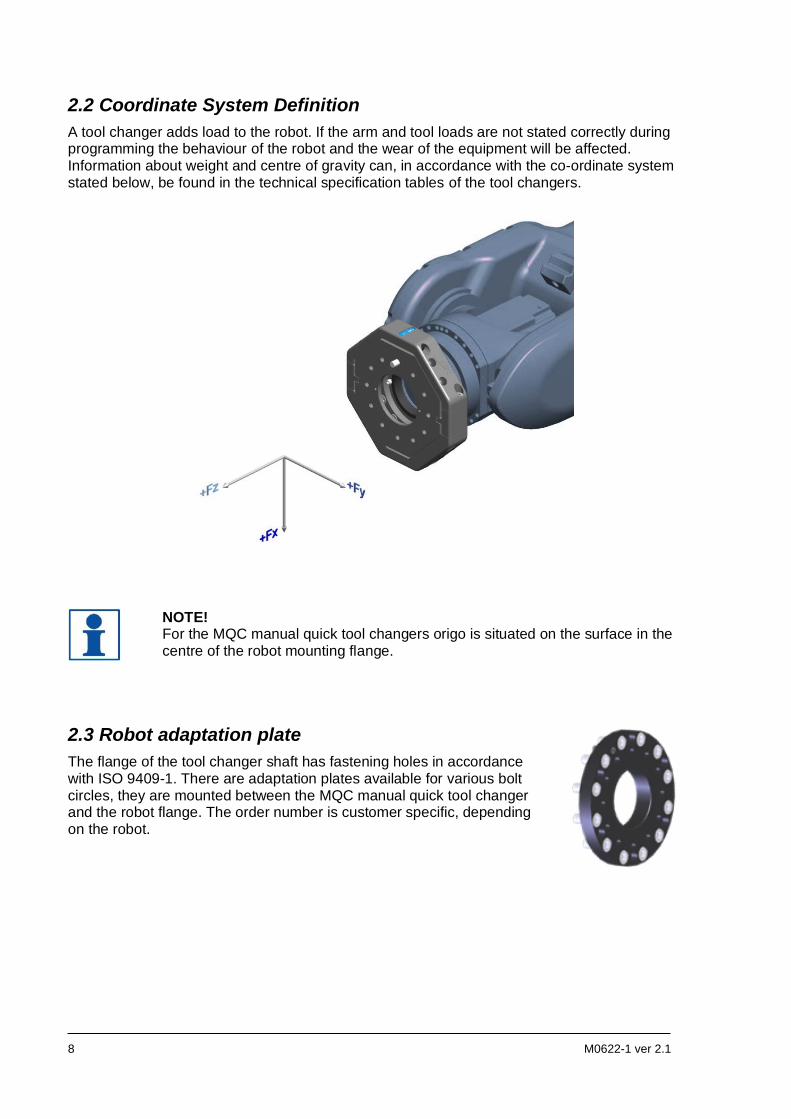
2.2 Coordinate System Definition
A tool changer adds load to the robot. If the arm and tool loads are not stated correctly during programming the behaviour of the robot and the wear of the equipment will be affected. Information about weight and centre of gravity can, in accordance with the co-ordinate system stated below, be found in the technical specification tables of the tool changers.
NOTE! For the MQC manual quick tool changers origo is situated on the surface in the centre of the robot mounting flange.
2.3 Robot adaptation plate
The flange of the tool changer shaft has fastening holes in accordance with ISO 9409-1. There are adaptation plates available for various bolt circles, they are mounted between the MQC manual quick tool changer and the robot flange. The order number is customer specific, depending on the robot.
M0622-1 ver 2.1 9
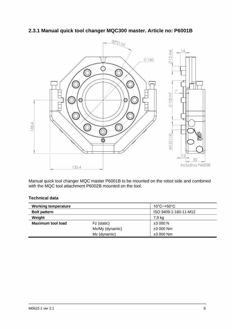
2.3.1 Manual quick tool changer MQC300 master. Article no: P6001B
Manual quick tool changer MQC master P6001B to be mounted on the robot side and combined with the MQC tool attachment P6002B mounted on the tool.
Technical data
Working temperature 10°C−+50°C
Bolt pattern ISO 9409-1-160-11-M12
Weight 7,9 kg
Maximum tool load Fz (static)
Mx/My (dynamic)
Mz (dynamic)
±3 000 N
±3 000 Nm
±3 000 Nm
10 M0622-1 ver 2.1
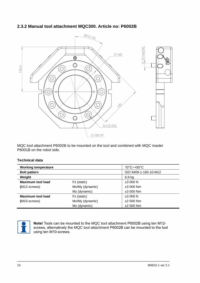
2.3.2 Manual tool attachment MQC300. Article no: P6002B
MQC tool attachment P6002B to be mounted on the tool and combined with MQC master P6001B on the robot side.
Technical data
Working temperature 10°C−+50°C
Bolt pattern ISO 9409-1-160-10-M12
Weight 6,9 kg
Maximum tool load
(M12-screws)
Fz (static)
Mx/My (dynamic)
Mz (dynamic)
±3 000 N
±3 000 Nm
±3 000 Nm
Maximum tool load
(M10-screws)
Fz (static)
Mx/My (dynamic)
Mz (dynamic)
±3 000 N
±2 500 Nm
±2 500 Nm
Note! Tools can be mounted to the MQC tool attachment P6002B using ten M12-screws, alternatively the MQC tool attachment P6002B can be mounted to the tool using ten M10-screws.
M0622-1 ver 2.1 11
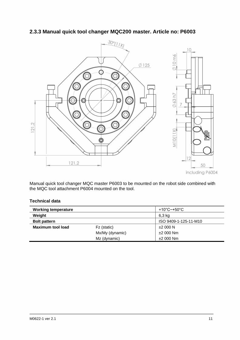
2.3.3 Manual quick tool changer MQC200 master. Article no: P6003
Manual quick tool changer MQC master P6003 to be mounted on the robot side combined with the MQC tool attachment P6004 mounted on the tool.
Technical data
Working temperature +10°C−+50°C
Weight 6,3 kg
Bolt pattern ISO 9409-1-125-11-M10
Maximum tool load
Fz (static)
Mx/My (dynamic)
Mz (dynamic)
±2 000 N
±2 000 Nm
±2 000 Nm
12 M0622-1 ver 2.1
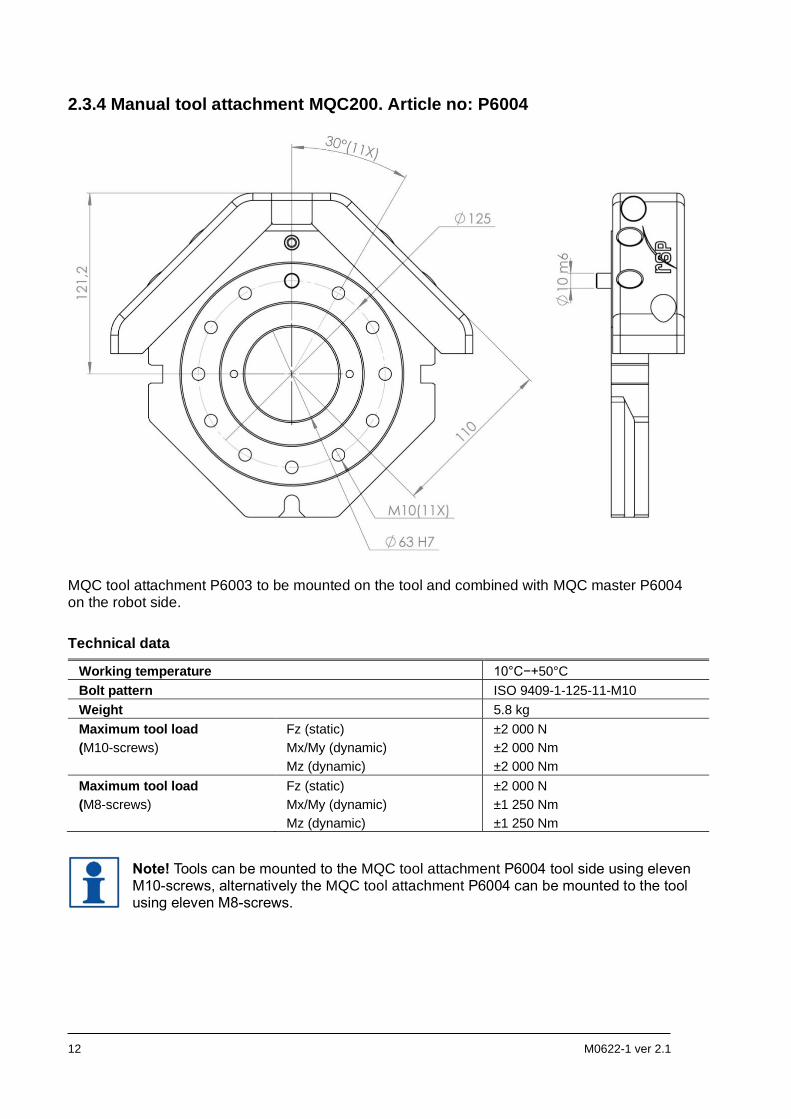
2.3.4 Manual tool attachment MQC200. Article no: P6004
MQC tool attachment P6003 to be mounted on the tool and combined with MQC master P6004 on the robot side.
Technical data
Working temperature 10°C−+50°C
Bolt pattern ISO 9409-1-125-11-M10
Weight 5.8 kg
Maximum tool load
(M10-screws)
Fz (static)
Mx/My (dynamic)
Mz (dynamic)
±2 000 N
±2 000 Nm
±2 000 Nm
Maximum tool load
(M8-screws)
Fz (static)
Mx/My (dynamic)
Mz (dynamic)
±2 000 N
±1 250 Nm
±1 250 Nm
Note! Tools can be mounted to the MQC tool attachment P6004 tool side using eleven M10-screws, alternatively the MQC tool attachment P6004 can be mounted to the tool using eleven M8-screws.
M0622-1 ver 2.1 13
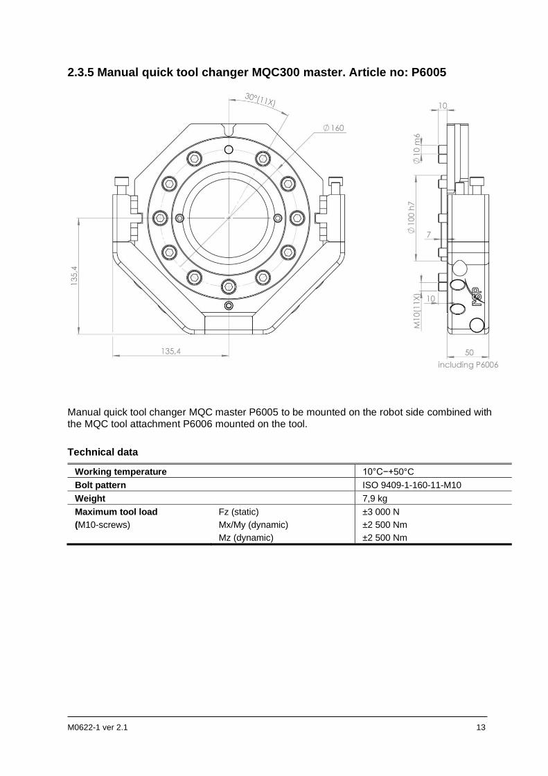
2.3.5 Manual quick tool changer MQC300 master. Article no: P6005
Manual quick tool changer MQC master P6005 to be mounted on the robot side combined with the MQC tool attachment P6006 mounted on the tool.
Technical data
Working temperature 10°C−+50°C
Bolt pattern ISO 9409-1-160-11-M10
Weight 7,9 kg
Maximum tool load
(M10-screws)
Fz (static)
Mx/My (dynamic)
Mz (dynamic)
±3 000 N
±2 500 Nm
±2 500 Nm
14 M0622-1 ver 2.1
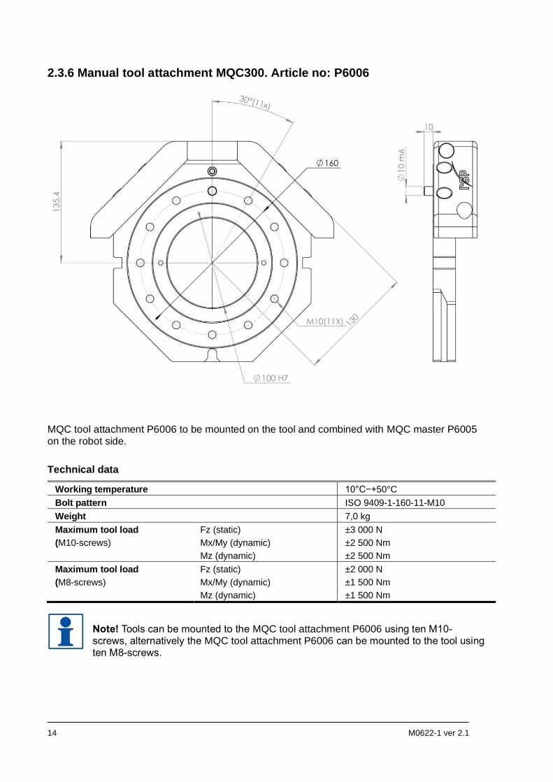
2.3.6 Manual tool attachment MQC300. Article no: P6006
MQC tool attachment P6006 to be mounted on the tool and combined with MQC master P6005 on the robot side.
Technical data
Working temperature 10°C−+50°C
Bolt pattern ISO 9409-1-160-11-M10
Weight 7,0 kg
Maximum tool load
(M10-screws)
Fz (static)
Mx/My (dynamic)
Mz (dynamic)
±3 000 N
±2 500 Nm
±2 500 Nm
Maximum tool load
(M8-screws)
Fz (static)
Mx/My (dynamic)
Mz (dynamic)
±2 000 N
±1 500 Nm
±1 500 Nm
Note! Tools can be mounted to the MQC tool attachment P6006 using ten M10-screws, alternatively the MQC tool attachment P6006 can be mounted to the tool using ten M8-screws.
M0622-1 ver 2.1 15
3 INSTALLATION
3.1 Tightening torques
Tightening torques for mounting (screw class 8.8)
Dimension Torque
M4 3 Nm
M5 6 Nm
M6 10 Nm
M8 24 Nm
M10 47 Nm
M12 82 Nm
M16 200 Nm
3.2 Recommended tools for installation
Tools Applications
Complete set of Allen keys For dismounting and mounting.
Torque wrench For all socket head cap screws
16 M0622-1 ver 2.1
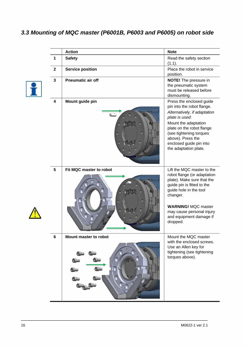
3.3 Mounting of MQC master (P6001B, P6003 and P6005) on robot side
Action Note
1 Safety Read the safety section
(1.1).
2 Service position Place the robot in service
position.
3 Pneumatic air off NOTE! The pressure in
the pneumatic system
must be released before
dismounting.
4 Mount guide pin
Press the enclosed guide
pin into the robot flange.
Alternatively, if adaptation
plate is used:
Mount the adaptation
plate on the robot flange
(see tightening torques
above). Press the
enclosed guide pin into
the adaptation plate.
5 Fit MQC master to robot
Lift the MQC master to the
robot flange (or adaptation
plate). Make sure that the
guide pin is fitted to the
guide hole in the tool
changer.
WARNING! MQC master
may cause personal injury
and equipment damage if
dropped.
6 Mount master to robot
Mount the MQC master
with the enclosed screws.
Use an Allen key for
tightening (see tightening
torques above).
M0622-1 ver 2.1 17
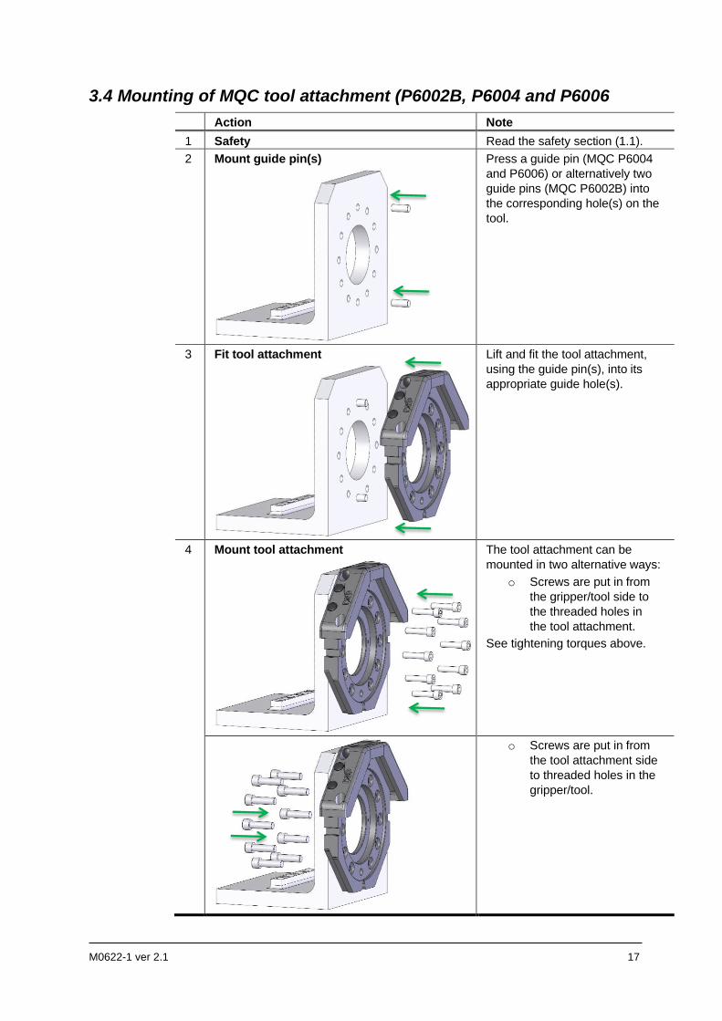
3.4 Mounting of MQC tool attachment (P6002B, P6004 and P6006
Action Note
1 Safety Read the safety section (1.1).
2 Mount guide pin(s)
Press a guide pin (MQC P6004
and P6006) or alternatively two
guide pins (MQC P6002B) into
the corresponding hole(s) on the
tool.
3 Fit tool attachment
Lift and fit the tool attachment,
using the guide pin(s), into its
appropriate guide hole(s).
4 Mount tool attachment
The tool attachment can be
mounted in two alternative ways:
o Screws are put in from
the gripper/tool side to
the threaded holes in
the tool attachment.
See tightening torques above.
o Screws are put in from
the tool attachment side
to threaded holes in the
gripper/tool.
18 M0622-1 ver 2.1
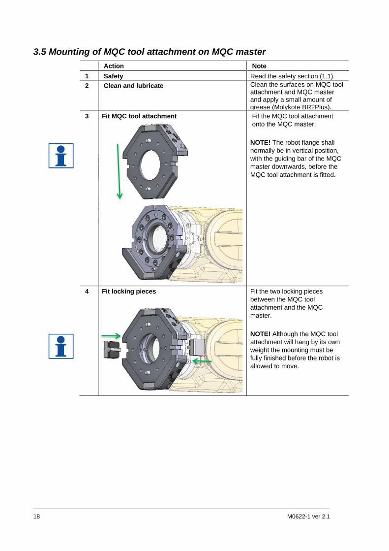
3.5 Mounting of MQC tool attachment on MQC master
Action Note
1 Safety Read the safety section (1.1).
2 Clean and lubricate Clean the surfaces on MQC tool attachment and MQC master and apply a small amount of grease (Molykote BR2Plus).
3 Fit MQC tool attachment
Fit the MQC tool attachment
onto the MQC master.
NOTE! The robot flange shall
normally be in vertical position,
with the guiding bar of the MQC
master downwards, before the
MQC tool attachment is fitted.
4 Fit locking pieces
Fit the two locking pieces
between the MQC tool
attachment and the MQC
master.
NOTE! Although the MQC tool
attachment will hang by its own
weight the mounting must be
fully finished before the robot is
allowed to move.
M0622-1 ver 2.1 19
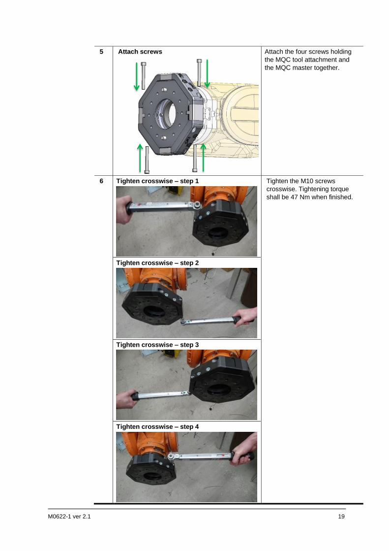
5 Attach screws
Attach the four screws holding
the MQC tool attachment and
the MQC master together.
6
Tighten crosswise – step 1
Tighten the M10 screws
crosswise. Tightening torque
shall be 47 Nm when finished.
Tighten crosswise – step 2
Tighten crosswise – step 3
Tighten crosswise – step 4
20 M0622-1 ver 2.1
4 MAINTENANCE AND SERVICE
4.1 Maintenance
The MQC manual quick tool changer requires a minimum of maintenance to ensure the proper function.
NOTE! Only perform work on grippers or tools attached to the MQC manual quick tool changer if the air pressure is safely switched off.
NOTE! The MQC manual quick tool changer must only be dismantled and repaired by Robot System Products during the warranty period. Otherwise the warranty will not be valid.
4.1.1 Required products
Product Specification Note
Cleaning agent Industrial alcohol or
similar
For MQC master and MQC tool attachment.
Grease I0876 Molykote BR2Plus For contact surfaces of MQC master and MQC
tool attachment.
Cloth Lint free cloth For cleaning.
NOTE! Chemical resistance protective gloves are recommended when using grease or cleaning agents such as denatured alcohol. Safety goggles are recommended when working with cleaning agents such as industrial alcohol. Adequate ventilation should be provided when chemical substances are used.
4.1.2 Recommended tools for maintenance
Tools Applications
Complete set of Allen keys For dismounting and mounting.
Torque wrench For all socket head cap screws
4.1.3 Activities and intervals
For MQC tool attachment and MQC master no preventive maintenance is required.
NOTE! Every time the MQC tool attachment and MQC master is remounted after being dismounted the contact surfaces should be cleaned and lubricated.
M0622-1 ver 2.1 21
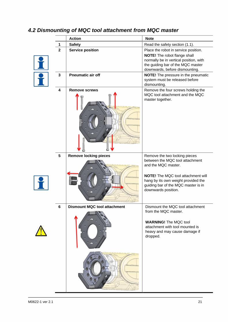
4.2 Dismounting of MQC tool attachment from MQC master
Action Note
1 Safety Read the safety section (1.1).
2 Service position Place the robot in service position.
NOTE! The robot flange shall
normally be in vertical position, with
the guiding bar of the MQC master
downwards, before dismounting.
3 Pneumatic air off NOTE! The pressure in the pneumatic
system must be released before
dismounting.
4 Remove screws
Remove the four screws holding the
MQC tool attachment and the MQC
master together.
5 Remove locking pieces
Remove the two locking pieces
between the MQC tool attachment
and the MQC master.
NOTE! The MQC tool attachment will
hang by its own weight provided the
guiding bar of the MQC master is in
downwards position.
6 Dismount MQC tool attachment
Dismount the MQC tool attachment
from the MQC master.
WARNING! The MQC tool
attachment with tool mounted is
heavy and may cause damage if
dropped.
22 M0622-1 ver 2.1
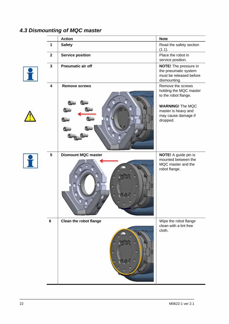
4.3 Dismounting of MQC master
Action Note
1 Safety Read the safety section
(1.1).
2 Service position
Place the robot in
service position.
3 Pneumatic air off NOTE! The pressure in
the pneumatic system
must be released before
dismounting.
4 Remove screws
Remove the screws
holding the MQC master
to the robot flange.
WARNING! The MQC
master is heavy and
may cause damage if
dropped.
5 Dismount MQC master
NOTE! A guide pin is
mounted between the
MQC master and the
robot flange.
6 Clean the robot flange
Wipe the robot flange
clean with a lint free
cloth.
M0622-1 ver 2.1 23
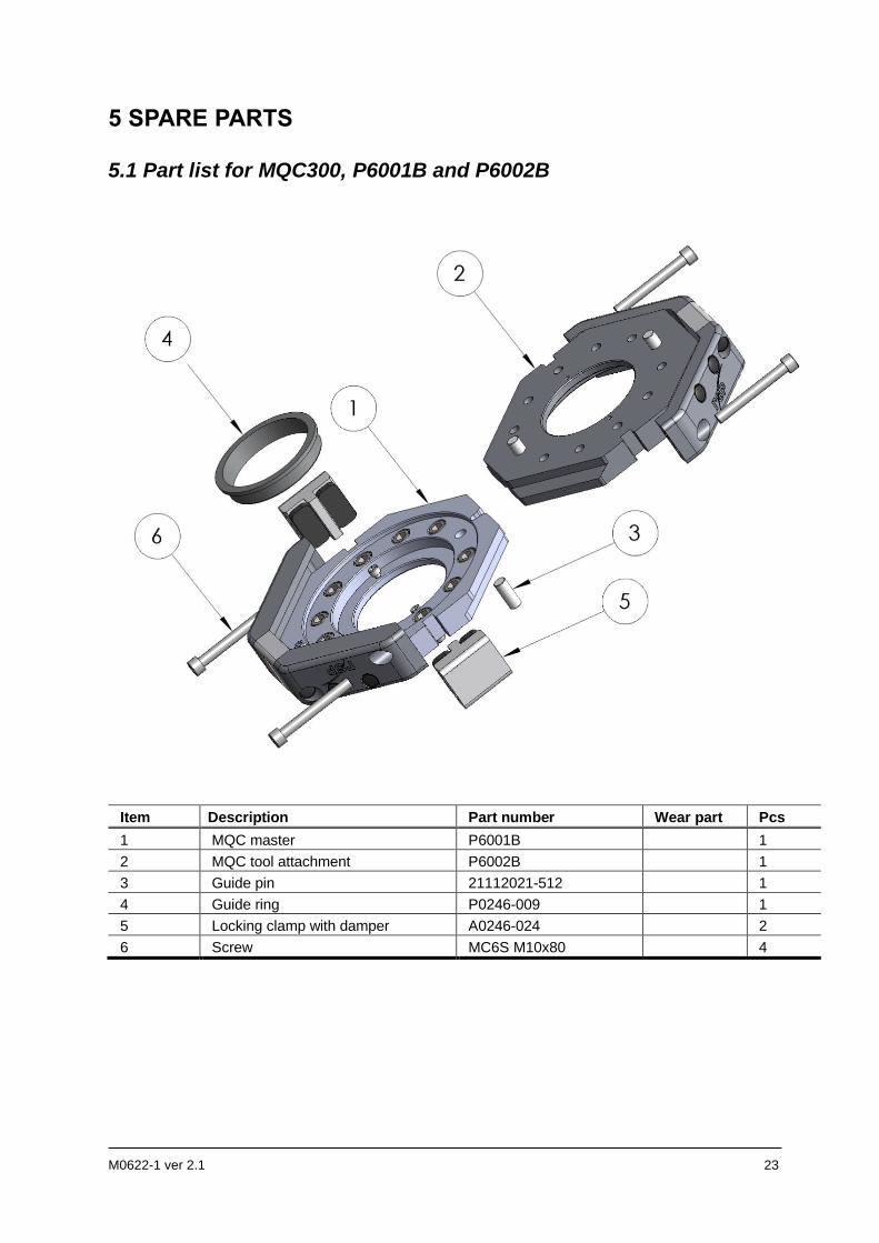
5 SPARE PARTS
5.1 Part list for MQC300, P6001B and P6002B
Item Description Part number Wear part Pcs
1 MQC master P6001B 1
2 MQC tool attachment P6002B 1
3 Guide pin 21112021-512 1
4 Guide ring P0246-009 1
5 Locking clamp with damper A0246-024 2
6 Screw MC6S M10x80 4
24 M0622-1 ver 2.1
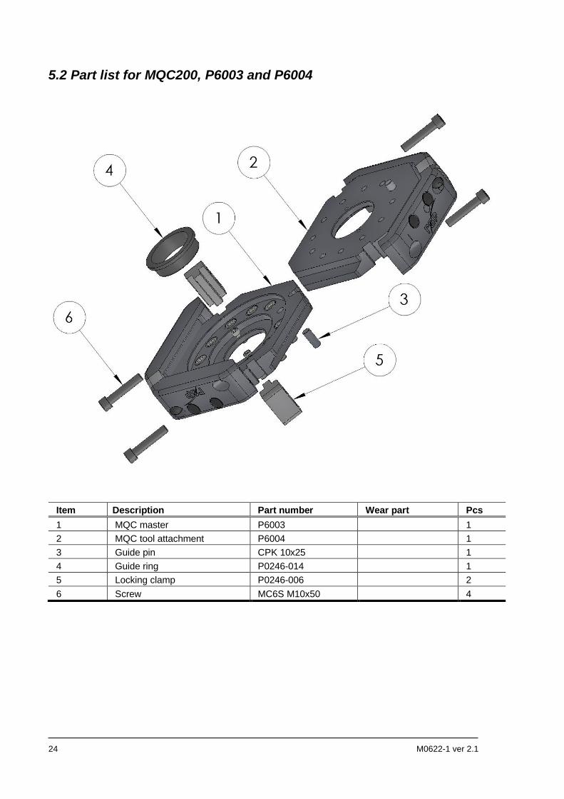
5.2 Part list for MQC200, P6003 and P6004
Item Description Part number Wear part Pcs
1 MQC master P6003 1
2 MQC tool attachment P6004 1
3 Guide pin CPK 10x25 1
4 Guide ring P0246-014 1
5 Locking clamp P0246-006 2
6 Screw MC6S M10x50 4
M0622-1 ver 2.1 25
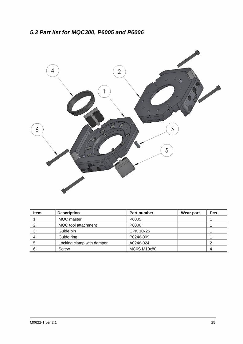
5.3 Part list for MQC300, P6005 and P6006
Item Description Part number Wear part Pcs
1 MQC master P6005 1
2 MQC tool attachment P6006 1
3 Guide pin CPK 10x25 1
4 Guide ring P0246-009 1
5 Locking clamp with damper A0246-024 2
6 Screw MC6S M10x80 4
26 M0622-1 ver 2.1
6 DISPOSAL AND RECYCLING
Taking care of spent equipment
Used equipment must be taken care of in an environmentally-friendly way.
When disposed of, a major share of the material, or its energy content, can be recycled. The quantities possible to recycle vary depending on technical resources and practises in respective country. Non-recyclable components shall be handed over to an authorized environmental waste treatment facility for destruction or disposal.
Electronics
Electronic equipment shall be sent to an authorized recycling company or sorted into different component materials and treated as such.
Metals
Metals can, in general, be melted down, recycled and used in new products. They shall be sorted according to type and surface coating and handed over to an authorized recycling facility.
Metal components of steel and aluminium are substantial in size and easy to identify. Copper is primarily used in transmission of power for spot welding. Silver or gold plating of contact surfaces may occur.
Plastics
Thermoplastics can, in general, be re-heated and recycled without any major loss of quality. They shall be handed over to an authorized recycling facility. POM occurs in swivel housings, etc. PTFE in some sealings.
Rubber
Rubber shall be handed over to an authorized environmental waste treatment facility either for recycling, disposal or destruction. Rubber occurs in O-rings.
Other material
All other material shall be sorted and handed to an authorized environmental waste treatment facility in accordance with national legislation.

M0622-1 ver 2.1 27

28 M0622-1 ver 2.1