product overview - university of arizona
TRANSCRIPT

• Measure up to 1000 volts with61 ⁄ 2 digits resolution
• 0.0015% basic dcV accuracy (24 hour)
• 0.06% basic acV accuracy (1 year)
• 3Hz to 300kHz ac bandwidth
• 1000 readings/sec. directto GPIB
Superior performanceThe Agilent Technologies 34401Amultimeter gives you the performanceyou need for fast, accurate bench andsystem testing. The 34401A providesa combination of resolution, accuracyand speed that rivals DMMs costingmany times more. 61⁄2-digits of resolu-tion, 0.0015% basic 24-hr dcV accu-racy and 1,000 readings/sec direct toGPIB assure you of results that areaccurate, fast, and repeatable.
Use it on your benchtop The 34401A was designed with yourbench needs in mind. Functions com-monly associated with bench opera-tion, like continuity and diode test,are built in. A Null feature allows youto remove lead resistance and otherfixed offsets in your measurements.Other capabilities like min/max/avgreadouts and direct dB and dBmmeasurements make checkout withthe 34401A faster and easier.
The 34401A gives youthe ability to store up to512 readings in internalmemory. For trouble-shooting, a reading holdfeature lets you concen-trate on placing yourtest leads without hav-ing to constantly glanceat the display.
Use it for systems testingFor systems use, the 34401A givesyou faster bus throughput than anyother DMM in its class. The 34401Acan send up to 1,000 readings/secdirectly across GPIB in user-friendlyASCII format.
You also get both GPIB and RS-232interfaces as standard features.Voltmeter Complete and ExternalTrigger signals are provided so youcan synchronize to other instrumentsin your test system. In addition, aTTL output indicates Pass/Failresults when limit testing is used.
To ensure both forward and back-ward compatibility, the 34401Aincludes three command languages(SCPI, Agilent 3478A and Fluke8840A /42A), so you don’t have torewrite your existing test software.An optional rack mount kit is avail-able.
Easy to useCommonly accessed attributes, suchas functions, ranges, and resolutionare selected with a single buttonpress.
Advanced features are available usingmenu functions that let you optimizethe 34401A for your applications.
To further increase your productivity,the 34401A can be used in conjunc-tion with HP 34812A BenchLinkMeter software. The Windows-basedprogram lets you configure and initi-ate measurements from your comput-er, and transfer results from your testinstrument to your PC. It even enablesdirect temperature measurementswith the 34401A and an RTD or ther-mistor probe. HP BenchLink Meteralso lets you create graphs, chartsand histo-grams to help you evaluateresults.
3-year warrantyWith your 34401A, you get full docu-mentation, a high-quality test leadset, calibration certificate with testdata, and a 3-year warranty, all forone low price.
Agilent 34401A Multimeter
Uncompromising Performance for Benchtopand System TestingProduct Overview

2
Accuracy Specifications ± (% of reading + % of range) [1]
Temperature Coefficient
Frequency, 24 Hour [2] 90 Day 1 Year 0°C – 18°CFunction Range[3] etc. 23°C ± 1°C 23°C ± 5°C 23°C ± 5°C 28°C – 55°C
dc Voltage 100.0000 mV 0.0030 + 0.0030 0.0040 + 0.0035 0.0050 + 0.0035 0.0005 + 0.00051.000000 V 0.0020 + 0.0006 0.0030 + 0.0007 0.0040 + 0.0007 0.0005 + 0.000110.00000 V 0.0015 + 0.0004 0.0020 + 0.0005 0.0035 + 0.0005 0.0005 + 0.0001100.0000 V 0.0020 + 0.0006 0.0035 + 0.0006 0.0045 + 0.0006 0.0005 + 0.00011000.000 V 0.0020 + 0.0006 0.0035 + 0.0010 0.0045 + 0.0010 0.0005 + 0.0001
True rms 100.0000 mV 3 Hz - 5 Hz 1.00 + 0.03 1.00 + 0.04 1.00 + 0.04 0.100 + 0.004ac Voltage[4] 5 Hz - 10 Hz 0.35 + 0.03 0.35 + 0.04 0.35 + 0.04 0.035 + 0.004
10 Hz - 20 kHz 0.04 + 0.03 0.05 + 0.04 0.06 + 0.04 0.005 + 0.00420 kHz - 50 kHz 0.10 + 0.05 0.11 + 0.05 0.12 + 0.04 0.011 + 0.00550 kHz - 100 kHz 0.55 + 0.08 0.60 + 0.08 0.60 + 0.08 0.060 + 0.008100 kHz - 300 kHz[6] 4.00 + 0.50 4.00 + 0.50 4.00 + 0.50 0.20 + 0.02
1.000000 V 3 Hz - 5 Hz 1.00 + 0.02 1.00 + 0.03 1.00 + 0.03 0.100 + 0.003to 5 Hz - 10 Hz 0.35 + 0.02 0.35 + 0.03 0.35 + 0.03 0.035 + 0.003
750.000 V 10 Hz - 20 kHz 0.04 + 0.02 0.05 + 0.03 0.06 + 0.03 0.005 + 0.00320 kHz - 50 kHz 0.10 + 0.04 0.11 + 0.05 0.12 + 0.04 0.011 + 0.00550 kHz - 100 kHz[5] 0.55 + 0.08 0.60 + 0.08 0.60 + 0.08 0.060 + 0.008100 kHz - 300 kHz[6] 4.00 + 0.50 4.00 + 0.50 4.00 + 0.50 0.20 + 0.02
Resistance[7] 100.0000 Ω 1 mA Current Source 0.0030 + 0.0030 0.008 + 0.004 0.010 + 0.004 0.0006 + 0.00051.000000 kΩ 1 mA 0.0020 + 0.0005 0.008 + 0.001 0.010 + 0.001 0.0006 + 0.000110.00000 kΩ 100 µA 0.0020 + 0.0005 0.008 + 0.001 0.010 + 0.001 0.0006 + 0.0001100.0000 kΩ 10 µA 0.0020 + 0.0005 0.008 + 0.001 0.010 + 0.001 0.0006 + 0.0001
1.000000 MΩ 5.0 µA 0.002 + 0.001 0.008 + 0.001 0.010 + 0.001 0.0010 + 0.000210.00000 MΩ 500 nA 0.015 + 0.001 0.020 + 0.001 0.040 + 0.001 0.0030 + 0.0004100.0000 MΩ 500 nA || 10MΩ 0.300 + 0.010 0.800 + 0.010 0.800 + 0.010 0.1500 + 0.0002
dc Current 10.00000 mA <0.1 V Burden Voltage 0.005 + 0.010 0.030 + 0.020 0.050 + 0.020 0.002 + 0.0020100.0000 mA <0.6 V 0.010 + 0.004 0.030 + 0.005 0.050 + 0.005 0.002 + 0.0005
1.000000 A <1 V 0.050 + 0.006 0.080 + 0.010 0.100 + 0.010 0.005 + 0.00103.00000 A <2 V 0.100 + 0.020 0.120 + 0.020 0.120 + 0.020 0.005 + 0.0020
True rms 1.000000 A 3 Hz - 5 Hz 1.00 + 0.04 1.00 + 0.04 1.00 + 0.04 0.100 + 0.006ac Current[4] 5 Hz - 10 Hz 0.30 + 0.04 0.30 + 0.04 0.30 + 0.04 0.035 + 0.006
10 Hz - 5 kHz 0.10 + 0.04 0.10 + 0.04 0.10 + 0.04 0.015 + 0.006
3.00000 A 3 Hz - 5 Hz 1.10 + 0.06 1.10 + 0.06 1.10 + 0.06 0.100 + 0.0065 Hz - 10 Hz 0.35 + 0.06 0.35 + 0.06 0.35 + 0.06 0.035 + 0.00610 Hz - 5 kHz 0.15 + 0.06 0.15 + 0.06 0.15 + 0.06 0.015 + 0.006
Frequency 100 mV 3 Hz - 5 Hz 0.10 0.10 0.10 0.005or Period[8] to 5 Hz - 10 Hz 0.05 0.05 0.05 0.005
750 V 10 Hz - 40 Hz 0.03 0.03 0.03 0.00140 Hz - 300 kHz 0.006 0.01 0.01 0.001
Continuity 1000.0Ω 1mA Test Current 0.002 + 0.010 0.008 + 0.020 0.010 + 0.020 0.001 + 0.002
Diode Test 1.0000V 1mA Test Current 0.002 + 0.010 0.008 + 0.020 0.010 + 0.020 0.001 + 0.002
254.4 mm
103.6 mm
374.0 mm 212.6 mm 348.3 mm
88.5 mm
[1] Specifications are for 1hr warm-up and 6 1⁄ 2 digits, Slow ac filter.[2] Relative to calibration standards.[3] 20% over range on all ranges except 1000Vdc and 750Vac ranges.[4] For sinewave input > 5% of range. For inputs from 1% to 5% of range
and < 50kHz, add 0.1% of range additional error.
[5] 750V range limited to 100 kHz or 8 x10⁷ Volt-Hz.[6] Typically 30% of reading error at 1MHz.[7] Specifications are for 4- wire ohms function or 2-wire ohms using Math Null.
Without Math Null, add 0.2 Ω additional error in 2-wire ohms function.[8] Input >100 mV. For 10 mV inputs multiply % of reading error x10.

3
Measurement Characteristics
dc Voltage
Measurement Method Continuously Integrating Multi-slope III
A-D Converter
A-D Linearity 0.0002% of reading + 0.0001 % of range
Input Resistance
0.1V, 1V,10 V ranges Selectable 10 MΩ or >10,000 MΩ100 V, 1000 V ranges 10 MΩ ± 1%
Input Bias Current < 30pA at 25° C
Input Protection 1000 V all ranges
dcV:dcV Ratio Accuracy Vinput Accuracy + Vreference Accuracy
True rms ac Voltage
Measurement Method ac coupled True rms – measures the ac
component of the input with up to 400 Vdc of
bias on any range.
Crest Factor Maximum of 5:1 at Full Scale
Additional Crest Factor Errors (non-sinewave)
Crest Factor 1–2 0.05 % of reading
Crest Factor 2–3 0.15 % of reading
Crest Factor 3–4 0.30 % of reading
Crest Factor 4–5 0.40 % of reading
Input Impedance 1 MΩ ± 2% in parallel with 100 pF
Input Protection 750Vrms all ranges
Resistance
Measurement Method Selectable 4-wire or 2-wire Ohms.
Current source referenced to LO input.
Maximum Lead Resistance 10% of range per lead for 100Ω and 1kΩ(4-wire) ranges. 1kΩ per lead on all other ranges.
Input Protection 1000 V all ranges
dc Current
Shunt Resistance 5Ω for 10 mA,100 mA; 0.1 Ω for 1 A, 3 A
Input Protection Externally accessible 3 A 250 V Fuse
Internal 7 A 250 V Fuse
True rms ac Current
Measurement Method Direct coupled to the fuse and shunt.
ac coupled True rms measurement
(measures the ac component only).
Shunt Resistance 0.1 Ω for 1 A and 3 A ranges
Input Protection ExternalIy accessible 3 A 250 V Fuse
Internal 7 A 250 V Fuse
Frequency and Period
Measurement Method Reciprocal counting technique
Voltage Ranges Same as ac Voltage Function
Gate Time 1 s, 100 ms, or 10 ms.
Continuity / Diode
Response Time 300 samples/s with audible tone
Continuity Threshold Selectable from 1 Ω to 1000 Ω
Measurement Noise Rejection 60 (50) Hz [1]
dc CMRR 140 dB
ac CMRR 70 dB
Integration Time Normal Mode Rejection [2]
100 plc / 1.67 s (2 s) 60 dB [3]
10 plc / 167 ms (200 ms) 60 dB [3]
1 plc / 16.7 ms (20 ms) 60 dB
<1 plc / 3 ms or 800 µs 0 dB
Operating Characteristics [4]
Function Digits Readings/s
dcV, dcI, and 61⁄ 2 0.6 (0.5)
Resistance 61⁄ 2 6 (5)
51⁄ 2 60 (50)
51⁄ 2 300
41⁄ 2 1000
acV, acI 61⁄ 2 0.15 Slow (3Hz)
61⁄ 2 1 Medium (20Hz)
61⁄ 2 10 Fast (200Hz)
61⁄ 2 50[5]
Frequency or 61⁄ 2 1
Period 51⁄ 2 9.8
41⁄ 2 80
System Speeds [6]
Configuration Rates 26/s to 50/s
Autorange Rate (dc Volts) > 30/s
ASCII readings to RS-232 55/s
ASCII readings to GPIB 1000/s
Maximum Internal Trig. Rate 1000/s
Max. Ext. Trig. Rate to Memory 1000/s
Triggering and Memory
Reading HOLD Sensitivity 10%, 1%, 0.1%,or 0.01% of range
Samples/ trigger 1 to 50,000
Trigger Delay 0 to 3600 s: 10 µs step size
External Trigger Delay < 1 ms
External Trigger Jitter < 500 µs
Memory 512 readings
Math Functions
NULL, Min/Max/Average, dBm, dB, Limit Test (with TTL output)
Standard Programming Languages
SCPI (IEEE-488.2), Agilent 3478A, Fluke 8840A/42A
Accessories Included
Test Lead Kit with probe, alligator, and grabber attachments.
Operating Manual, Service Manual, test report, and power cord.
General Specifications
Power Supply 100 V/120 V/220 V/240 V ±10%
Power Line Frequency 45 Hz to 66 Hz and 360 Hz to 440 Hz
Automatically sensed at power-on
Power Consumption 25 VA peak (10W average)
Operating Environment Full accuracy for 0° C to 55° C
Full accuracy to 80% R.H. at 40° C
Storage Environment – 40° C to 70° C
Weight 3.6 kg (8.0 Ibs)
Safety Designed to CSA, UL-1244, IEC-348
RFI and ESD MIL-461C, FTZ 1046, FCC
Vibration and Shock MIL-T-28800E, Type III, Class 5 (Sine Only)
Warranty 3 years[1] For 1kΩ unbalance in LO lead. [2] For power line frequency ± 0.1%. [3] For power line frequency ± 1% use 40dB or ± 3% use 30dB.[4] Reading speeds for 60Hz and (50Hz) operation.[5] Maximum useful limit with default settling delays defeated.[6] Speeds are for 41 ⁄ 2 digits, Delay 0, Auto-zero and Display OFF.

Ordering InformationAgilent 34401A MultimeterAccessories included
Test Lead Kit with probe, alligator, and grabber attachments, operatingmanual, service manual, calibration certificate, test report, and power cord.
OptionsOpt. 908 Rack Mount Kit* (P/N 5062-3972)Opt. 910 Extra manual set (English)Opt. OBO DMM without manualsOpt. W50 Additional 2-year warranty (5-year total)Opt. 1BP MIL-STD-45662A calibration with data
Manual options (please specify one)ABA US EnglishABD GermanABE SpanishABF FrenchABJ JapaneseABZ ItalianABO Taiwan ChineseAB1 KoreanAB2 ChineseAKT Russian
Agilent Accessories11059A Kelvin Probe set11060A Surface Mount Device (SMD) test probes11062A Kelvin clip set34131 Hard Transit Case34161A Accessory pouch34330A 30 A current shunt34812A BenchLink Meter softwareE2308A 5K thermistor probe
*For racking two side-by-side, order both items belowLock link kit (P/N 5061-9694)Flange kit (P/N 5063-9212)
Agilent Technologies’ Test and MeasurementSupport, Services, and AssistanceAgilent Technologies aims to maximize the value you receive, while minimizingyour risk and problems. We strive toensure that you get the test and measure-ment capabilities you paid for and obtainthe support you need. Our extensive sup-port resources and services can help youchoose the right Agilent products for yourapplications and apply them successfully.Every instrument and system we sell has a global warranty. Support is available for at least five years beyond the produc-tion life of the product. Two conceptsunderlie Agilent’s overall support policy:“Our Promise” and “Your Advantage.”
Our Promise“Our Promise” means your Agilent testand measurement equipment will meet itsadvertised performance and functionality.When you are choosing new equipment,we will help you with product informa-tion, including realistic performance spec-ifications and practical recommendationsfrom experienced test engineers. Whenyou use Agilent equipment, we can verifythat it works properly, help with productoperation, and provide basic measurementassistance for the use of specified capabil-ities, at no extra cost upon request. Manyself-help tools are available.
Your Advantage“Your Advantage” means that Agilentoffers a wide range of additional experttest and measurement services, which youcan purchase according to your uniquetechnical and business needs. Solve prob-lems efficiently and gain a competitive edgeby contracting with us for calibration, extra-cost upgrades, out-of-warranty repairs, andon-site education and training, as well as design, system integration, project man-agement, and other professional services.Experienced Agilent engineers and techni-cians worldwide can help you maximizeyour productivity, optimize the return oninvestment of your Agilent instruments andsystems, and obtain dependable measure-ment accuracy for the life of those products.
Get assistance with all your test and measurement needs at: www.agilent.com/find/assistOr check your local phone book for theAgilent office near you.
Product specifications and descriptions in this document subject to change without notice.
Copyright © 1998, 2000 Agilent TechnologiesPrinted in U.S.A. 5/005968-0162 EN

To Measure Voltage Ranges: 100 mV, 1 V, 10 V, 100 V, 1000 V (750 Vac)Maximum resolution: 100 nV (on 100 mV range)AC technique: true RMS, ac-coupled
To Measure Resistance
Ranges: 100 Ω, 1 kΩ, 10 kΩ, 100 kΩ, 1 MΩ, 10 MΩ, 100 MΩMaximum resolution: 100 µΩ (on 100 ohm range)
1
Chapter 1 Quick Start To Measure Voltage
17
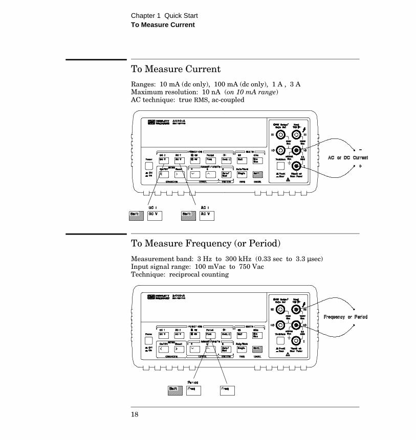
To Measure Current Ranges: 10 mA (dc only), 100 mA (dc only), 1 A , 3 AMaximum resolution: 10 nA (on 10 mA range)AC technique: true RMS, ac-coupled
To Measure Frequency (or Period)
Measurement band: 3 Hz to 300 kHz (0.33 sec to 3.3 µsec)Input signal range: 100 mVac to 750 VacTechnique: reciprocal counting
Chapter 1 Quick Start To Measure Current
18

To Test Continuity Test current source: 1 mAMaximum resolution: 0.1 Ω (range is fixed at 1 kohm)Beeper threshold: 1 Ω to 1000 Ω (beeps below adjustable threshold)
To Check Diodes Test current source: 1 mAMaximum resolution: 100 µV (range is fixed at 1 Vdc)Beeper threshold: 0.3 volts ≤ Vmeasured ≤ 0.8 volts (not adjustable)
1
Chapter 1 Quick Start To Test Continuity
19

To Select a Range You can let the multimeter automatically select the range usingautoranging or you can select a fixed range using manual ranging.
• Autoranging is selected at power-on and after a remote interface reset.
• Autorange thresholds: Down range at <10% of range Up range at >120% of range
• If the input signal is greater than the present range can measure,the multimeter will give an overload indication (“OVLD”).
• For frequency and period measurements from the front panel,ranging applies to the signal’s input voltage, not its frequency.
• The range is fixed for continuity (1 kΩ range) and diode (1 Vdc range).
Ranging is local to the selected function. This means that you can selectthe ranging method (auto or manual) for each function independently.When manually ranging, the selected range is local to the function; the multimeter remembers the range when you switch between functions.
Selects a lower range and disables autoranging.
Man annunciator is on when manual range is enabled.
Selects a higher range and disables autoranging.
Toggles between autoranging and manual ranging.
Chapter 1 Quick Start To Select a Range
20

To Set the Resolution You can set the display resolution to 41⁄2, 51⁄2, or 61⁄2 digits either tooptimize measurement speed or noise rejection. In this book, the mostsignificant digit (leftmost on the display) is referred to as the “1⁄2” digit,since it can only be a “0” or “1.”
• The resolution is set to 51⁄2 digits at power-on and after a remoteinterface reset.
• The resolution is fixed at 51⁄2 digits for continuity and diode tests.
• You can also vary the number of digits displayed using the arrow keys(however, the integration time is not changed).
Resolution is local to the selected function. This means that you canselect the resolution for each function independently. The multimeterremembers the resolution when you switch between functions.
Press the Shift key.
Selects 41⁄2 digits.
Selects 51⁄2 digits.
Selects 61⁄2 digits (most noise rejection).
Fewer MoreDigits Digits
1
Chapter 1 Quick Start To Set the Resolution
21

Front-Panel Display Formats
-H.DDD,DDD EFFF
Front-panel display format.
10.216,5 VDC
This is the 10 Vdc range, 51⁄2 digits are displayed.
-045.23 mVDC
This is the 100 mVdc range, 41⁄2 digits are displayed.
113.325,6 OHM
This is the 100 ohm range, 61⁄2 digits are displayed.
OVL.D mVDC
This is an overload indication on the 100 mVdc range.
“1⁄2” digit
5 digits
– Negative sign or blank (positive)H “ 1⁄2 ” digit (0 or 1)D Numeric digitsE Exponent ( m, k, M )F Measurement units ( VDC, OHM, HZ, dB )
“1⁄2” digit
Chapter 1 Quick Start Front-Panel Display Formats
22

Resistance Measurements
The HP 34401A offers two methods for measuring resistance: 2-wireand 4-wire ohms. For both methods, the test current flows from theinput HI terminal and then through the resistor being measured. For 2-wireohms, the voltage drop across the resistor being measured is sensedinternal to the multimeter. Therefore, test lead resistance is alsomeasured. For 4-wire ohms, separate “sense” connections are required.Since no current flows in the sense leads, the resistance in these leadsdoes not give a measurement error.
The errors mentioned earlier in this chapter for dc voltage measurementsalso apply to resistance measurements. Additional error sources uniqueto resistance measurements are discussed on the following pages.
4-Wire Ohms Measurements
The 4-wire ohms method provides the most accurate way to measuresmall resistances. Test lead resistances and contact resistances areautomatically reduced using this method. Four-wire ohms is often usedin automated test applications where long cable lengths, numerousconnections, or switches exist between the multimeter and the device-under-test. The recommended connections for 4-wire ohmsmeasurements are shown below. See also “To Measure Resistance,”on page 17.
I test
Ideal Meter
HI
LO
LO-Sense
HI-Sense
R = Vmeter
Itest
7
Chapter 7 Measurement Tutorial Resistance Measurements
203
True RMS AC Measurements
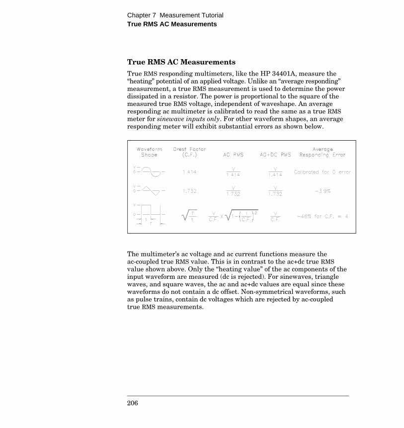
True RMS responding multimeters, like the HP 34401A, measure the“heating” potential of an applied voltage. Unlike an “average responding”measurement, a true RMS measurement is used to determine the powerdissipated in a resistor. The power is proportional to the square of themeasured true RMS voltage, independent of waveshape. An averageresponding ac multimeter is calibrated to read the same as a true RMSmeter for sinewave inputs only. For other waveform shapes, an averageresponding meter will exhibit substantial errors as shown below.
The multimeter’s ac voltage and ac current functions measure theac-coupled true RMS value. This is in contrast to the ac+dc true RMSvalue shown above. Only the “heating value” of the ac components of theinput waveform are measured (dc is rejected). For sinewaves, trianglewaves, and square waves, the ac and ac+dc values are equal since thesewaveforms do not contain a dc offset. Non-symmetrical waveforms, suchas pulse trains, contain dc voltages which are rejected by ac-coupledtrue RMS measurements.
Chapter 7 Measurement Tutorial True RMS AC Measurements
206

An ac-coupled true RMS measurement is desirable in situations whereyou are measuring small ac signals in the presence of large dc offsets.For example, this situation is common when measuring ac ripplepresent on dc power supplies. There are situations, however, where youmight want to know the ac+dc true RMS value. You can determine thisvalue by combining results from dc and ac measurements as shownbelow. You should perform the dc measurement using at least 10 powerline cycles of integration (6 digit mode) for best ac rejection.
Crest Factor Errors (non-sinusoidal inputs)A common misconception is that “since an ac multimeter is true RMS,its sinewave accuracy specifications apply to all waveforms.” Actually,the shape of the input signal can dramatically affect measurementaccuracy. A common way to describe signal waveshapes is crest factor.Crest factor is the ratio of the peak value to RMS value of a waveform.
For a pulse train, for example, the crest factor is approximately equal tothe square root of the inverse of the duty cycle as shown in the table onthe previous page. In general, the greater the crest factor, the greaterthe energy contained in higher frequency harmonics. All multimetersexhibit measurement errors that are crest factor dependent. Crest factorerrors for the HP 34401A are shown in the specifications in chapter 8.Note that the crest factor errors do not apply for input signals below100 Hz when using the slow ac filter.
ac + dc = ac2 + dc2√
7
Chapter 7 Measurement Tutorial Crest Factor Errors (non-sinusoidal inputs)
207