production and casting of metals isen 3723 dr. darrell r. wallace department of mechanical &...
TRANSCRIPT
Production and Casting of Metals
ISEN 3723Dr. Darrell R. Wallace
Department of Mechanical & Industrial EngineeringCollege of STEM
Youngstown State University
SOLIDIFICATION OF METALSCasting Processes
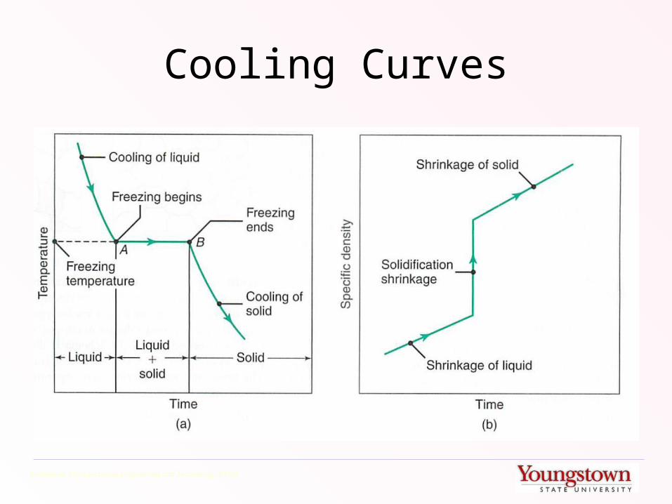
Cooling Curves
Kalpakjian, Manufacturing Engineering and Technology, 6th Ed.

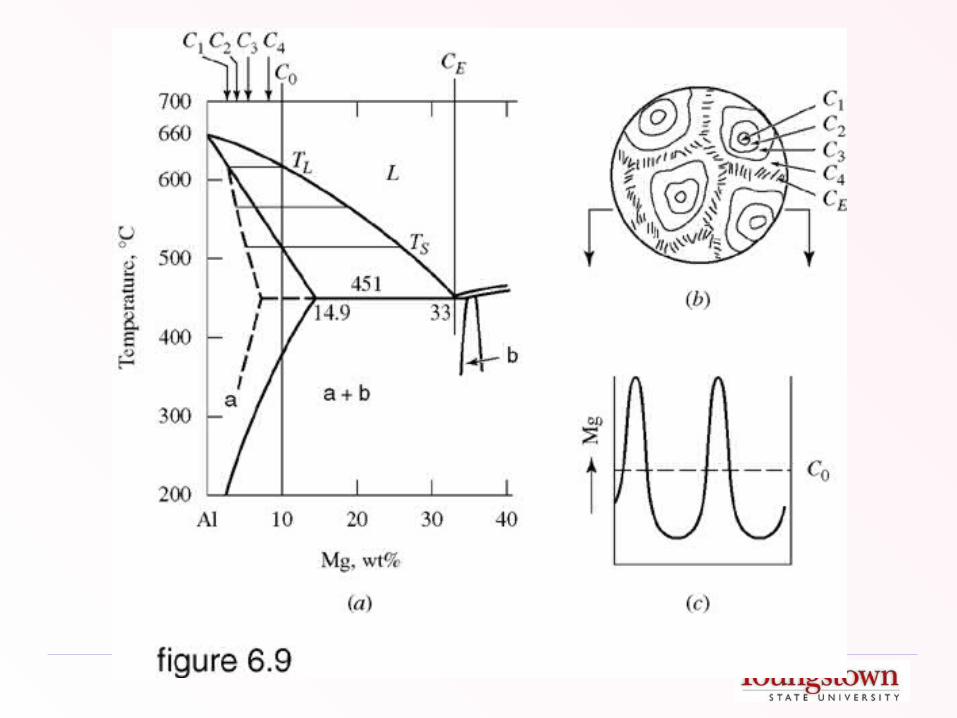
Phase Diagram and Cooling Curve

(Inverse) Lever Rule
Chvorinov’s Rule
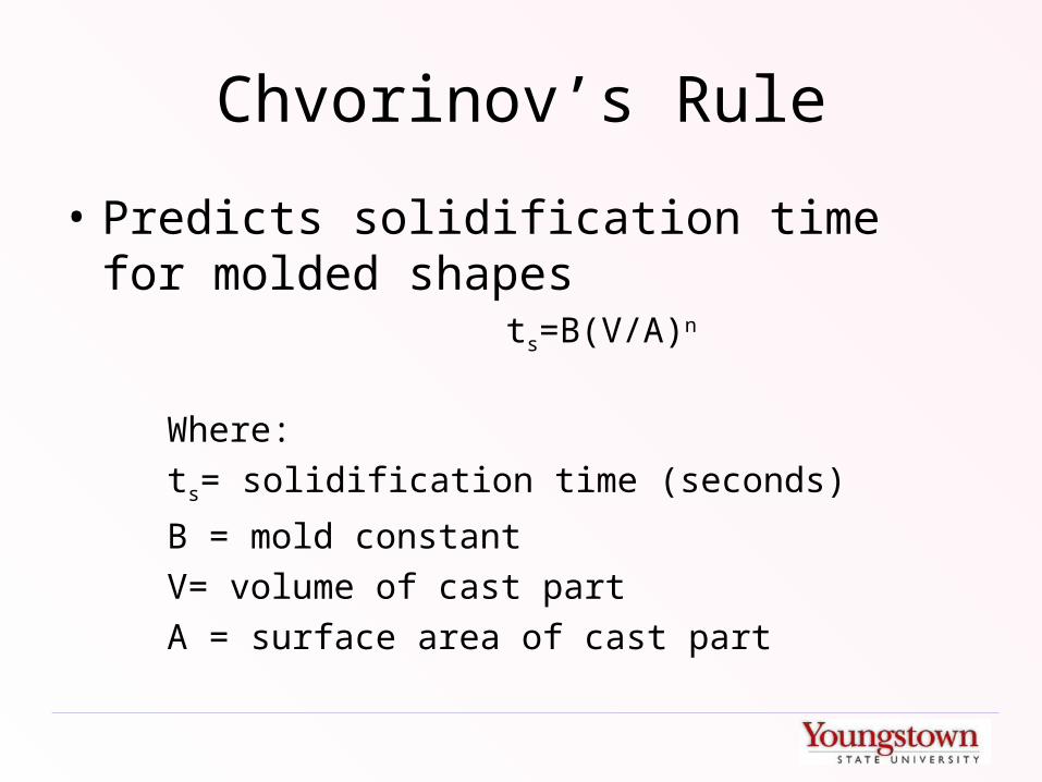
• Predicts solidification time for molded shapes
ts=B(V/A)n
Where:
ts= solidification time (seconds)
B = mold constant
V= volume of cast part
A = surface area of cast part
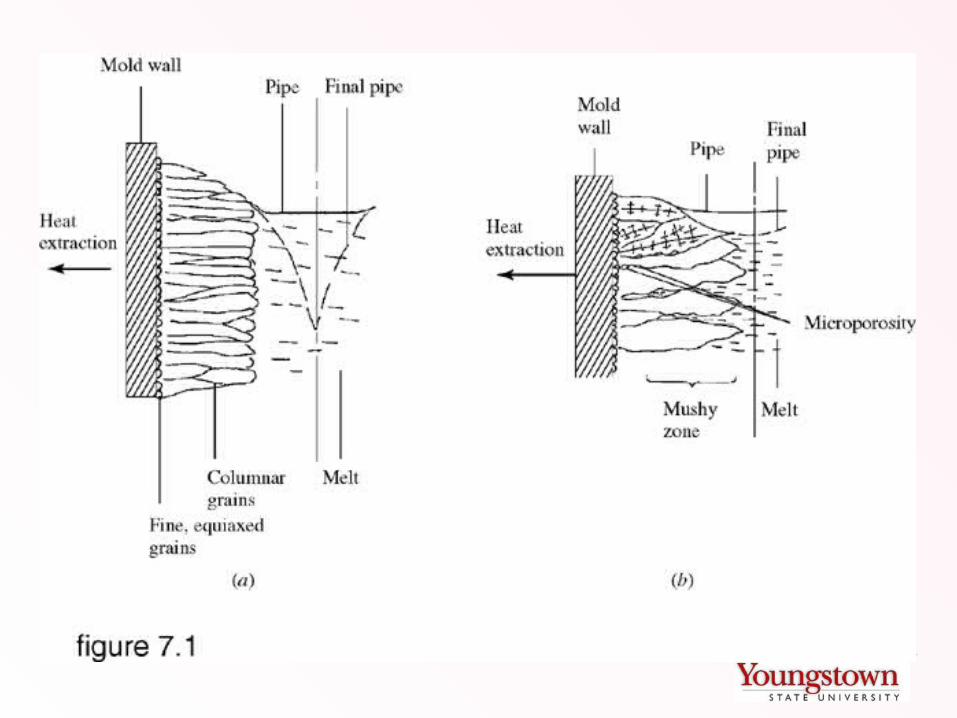
Grain Structure in Casting
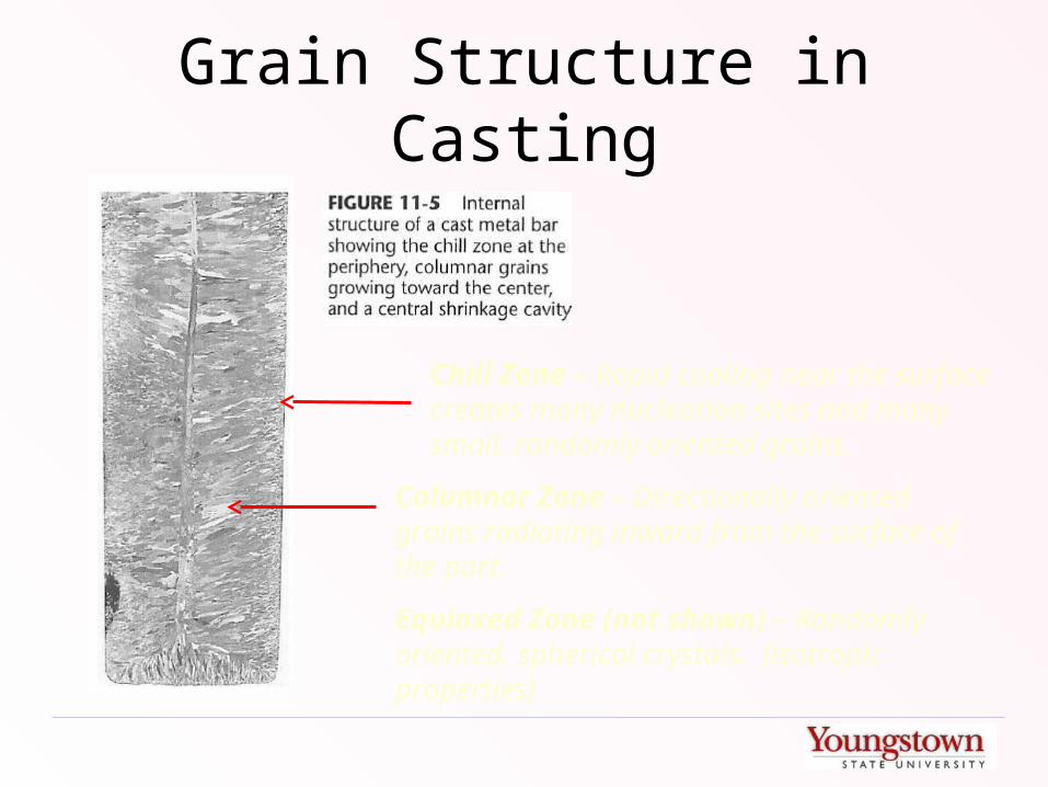
Chill Zone – Rapid cooling near the surface creates many nucleation sites and many small, randomly oriented grains.
Columnar Zone – Directionally oriented grains radiating inward from the surface of the part.
Equiaxed Zone (not shown) – Randomly oriented, spherical crystals. (isotropic properties)
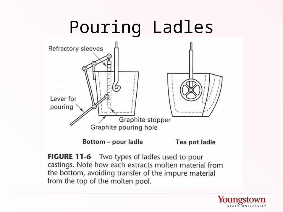
Pouring Ladles
Challenges of Molten Metal
• Hot metal readily forms oxides (dross or slag)– Can be carried into the mold– Can be controlled by pouring methods– Control of temperature and atmosphere can
slow creation of slag

Challenges of Molten Metal
• Dissolved gases– Porosity
– Can be controlled by:• Vacuum degassing
• Gas flushing
• “Killing” - Reacting trapped gas with material that will form buoyant compound that will float to surface
– Oxygen removed from copper by adding phosphorous
– Oxygen removed from steel by adding aluminum or silicon

Challenges of Molten Metal
• Temperature Control– Temp too Low
• Misruns• Cold shuts
– Temp too High• Excessive mold wear• Higher reactivity of molten metal• Penetration defects (excessive flash or entrapped
sand)

SHAPE CASTING PROCESSESCasting Processes
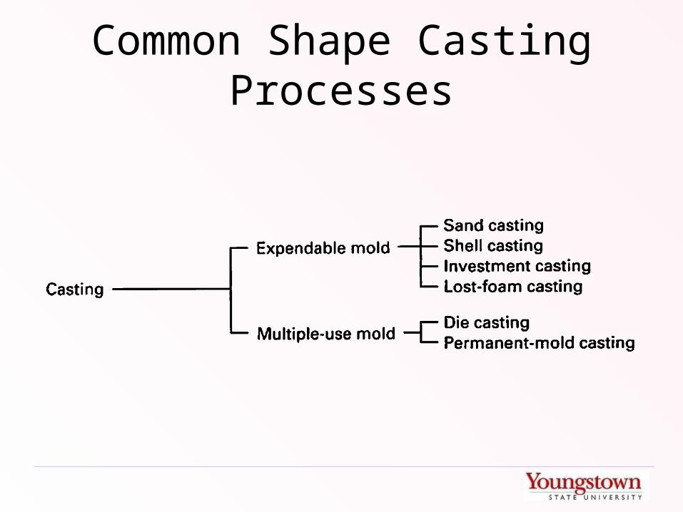
Common Shape Casting Processes
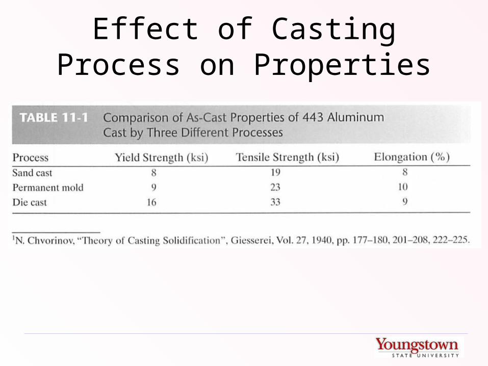
Effect of Casting Process on Properties
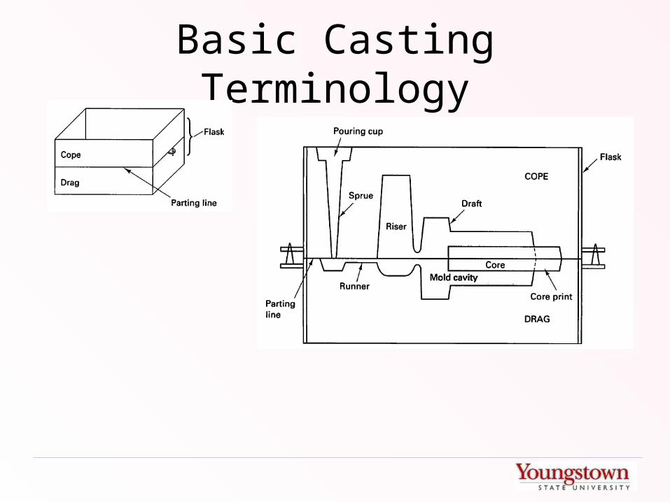
Basic Casting Terminology

Runners and Gates
• Should distribute metal to all parts of casting(s)
• Should control flow rate
• Should be laminar flow
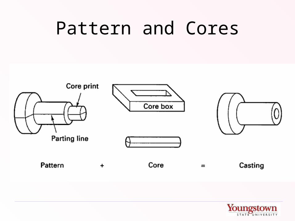
Pattern and Cores
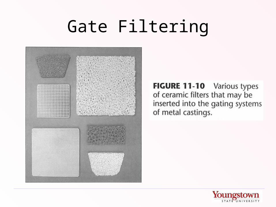
Gate Filtering
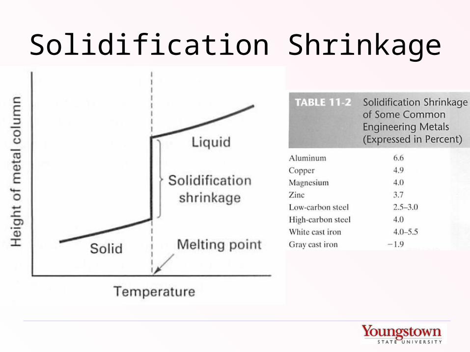
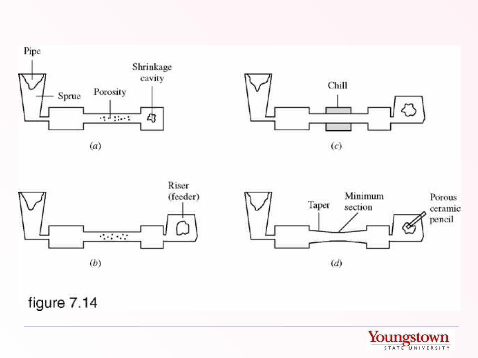
Solidification Shrinkage
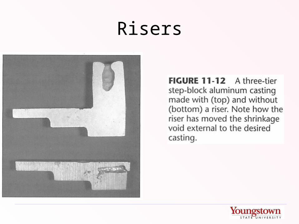
Risers

Risers• Provide additional material to fill in as
shrinkage occurs• Live risers receive hot metal directly entering the
mold
• Dead risers are filled by hot metal that has already passed through the mold
• Blind risers are closed to the atmosphere
• Open risers penetrate through the mold cavity
• Side risers feed the part through the runner / gate system
• Top risers are attached directly to the part

Risers
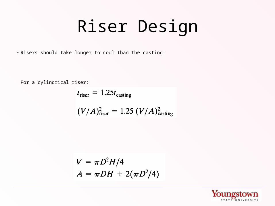
Riser Design• Risers should take longer to cool than the casting:
For a cylindrical riser:

Risering Aids
• Internal Chills – Extract or absorb heat through the mold walls
• External Chills – Thermal sinks placed inside the mold cavity (become part of the finished casting)
• Insulating Sleeves – Limit heat transfer out of the riser
• Exothermic Materials – Add heat to the riser
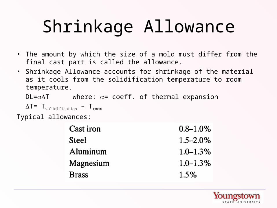
Shrinkage Allowance
• The amount by which the size of a mold must differ from the final cast part is called the allowance.
• Shrinkage Allowance accounts for shrinkage of the material as it cools from the solidification temperature to room temperature.
DL=T where: = coeff. of thermal expansion
T= Tsolidification – Troom
Typical allowances:
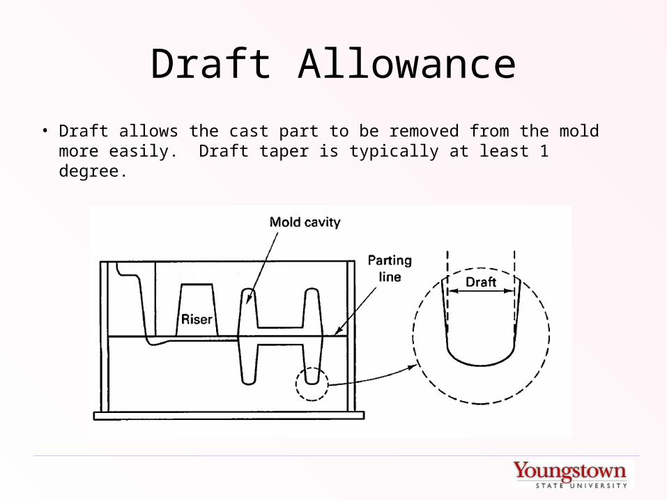
Draft Allowance
• Draft allows the cast part to be removed from the mold more easily. Draft taper is typically at least 1 degree.
Finish Allowance
• Where a part requires a precise surface or dimensional tolerance, most castings will have to be machined. In these cases, extra material must be cast so that it may be machined to size. The extra material provided is called a finish or machining allowance.

Combined Allowances

Design Considerations in Castings
• Location / Orientation of Parting Plane affects:– Number of cores– Method of supporting cores– Gating– Casting weight– Dimensional accuracy– Ease of molding

Good Parting Line Choice
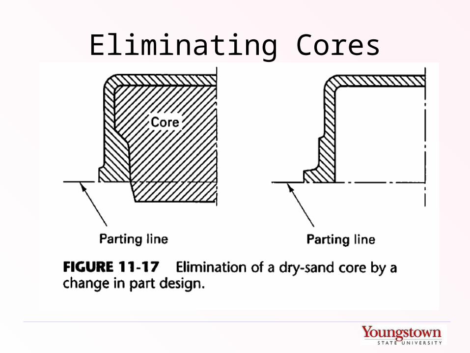
Eliminating Cores

Effect of Alternate Parting Lines
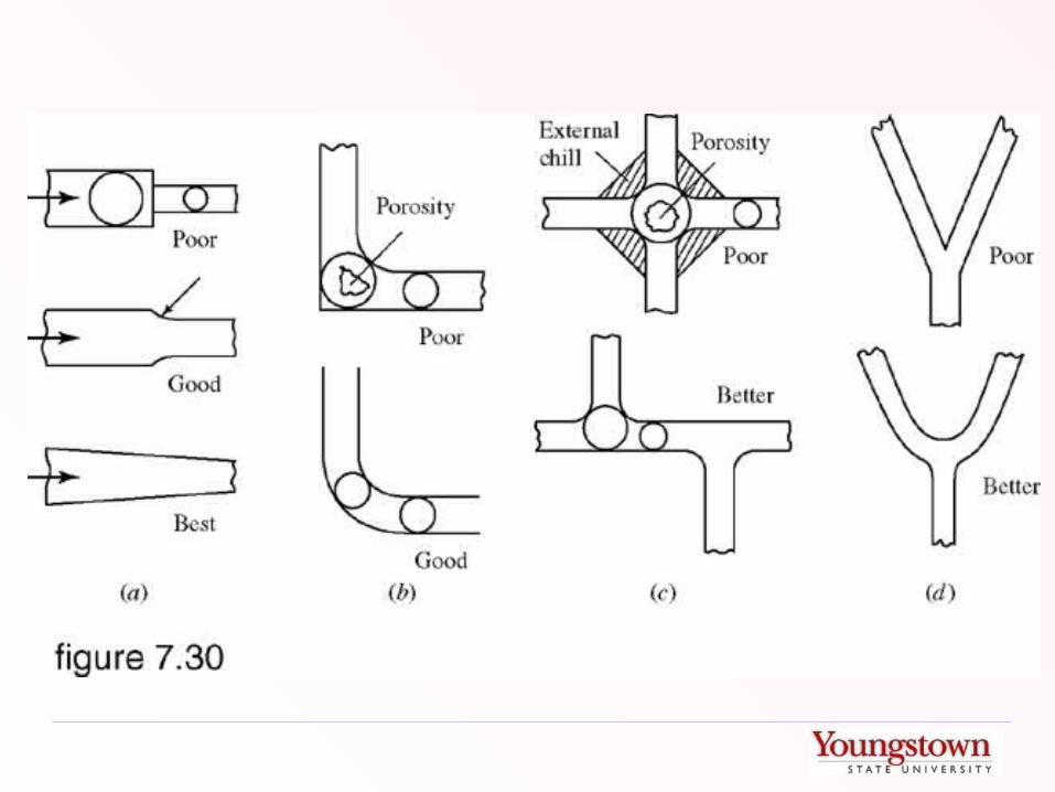
Section Change Transitions
• Where the section thickness of a cast part changes, two problems can arise:– Stress concentrations– Hot spots

Section Change Transitions
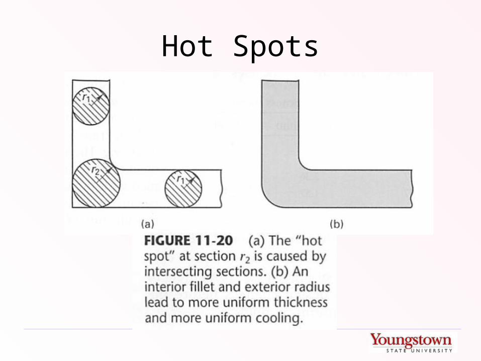
Hot Spots

Hot Spots and Shrinkage Cavities
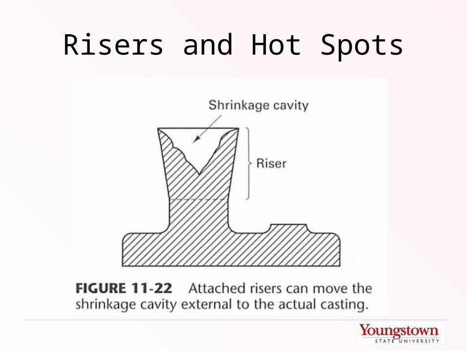
Risers and Hot Spots

Rib Placement

Minimum Section Thicknesses

Sand Casting
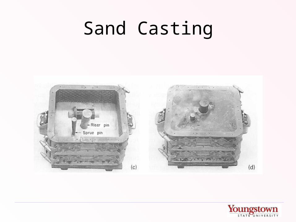
Sand Casting
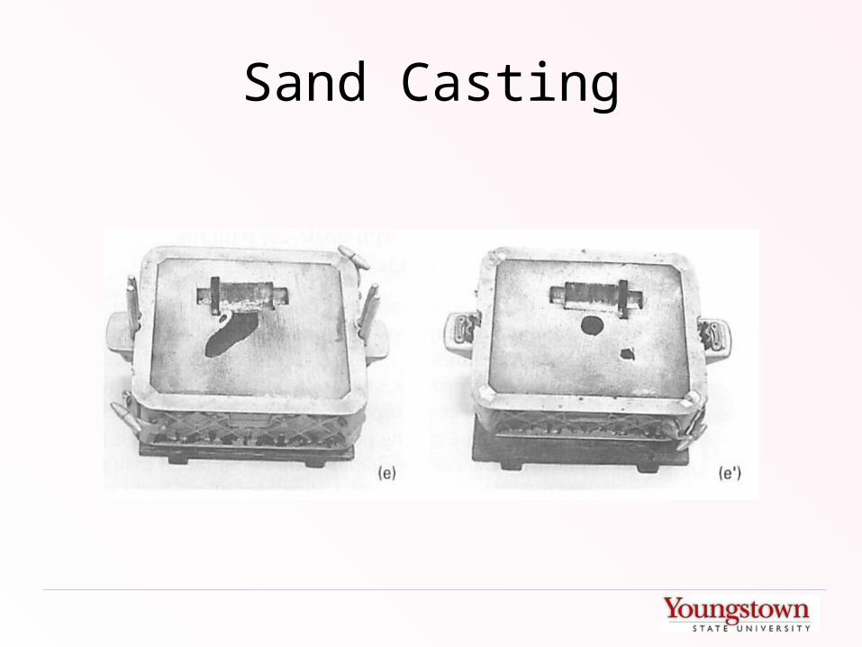
Sand Casting
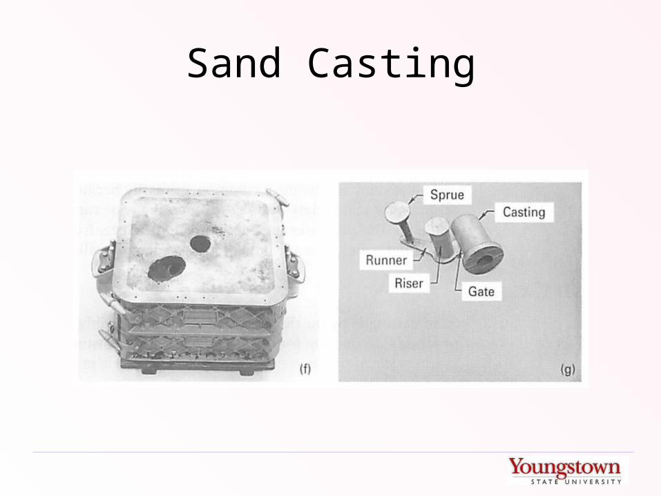
Sand Casting
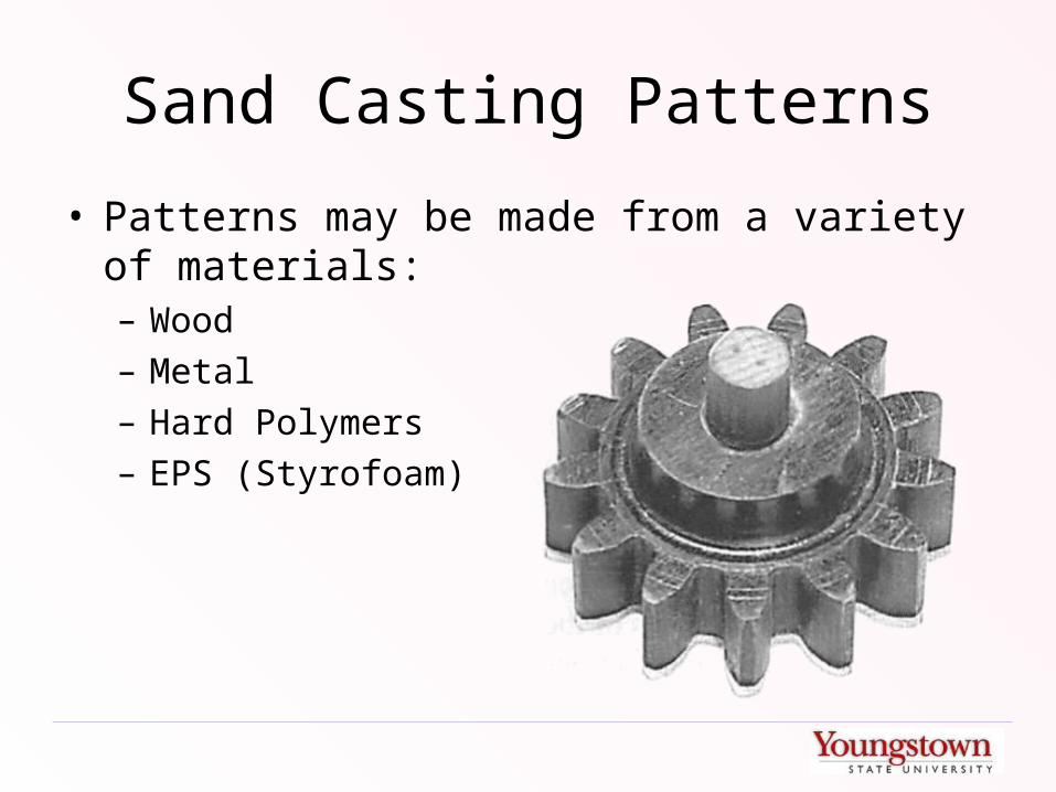
Sand Casting Patterns
• Patterns may be made from a variety of materials:– Wood– Metal– Hard Polymers– EPS (Styrofoam)

Types of Sand Casting Patterns
• One-Piece
Types of Sand Casting Patterns
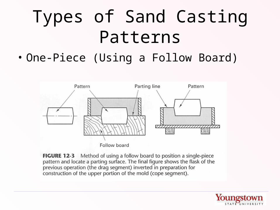
• One-Piece (Using a Follow Board)
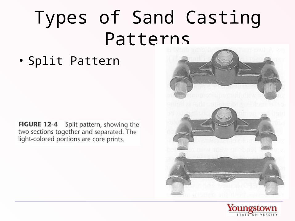
Types of Sand Casting Patterns
• Split Pattern
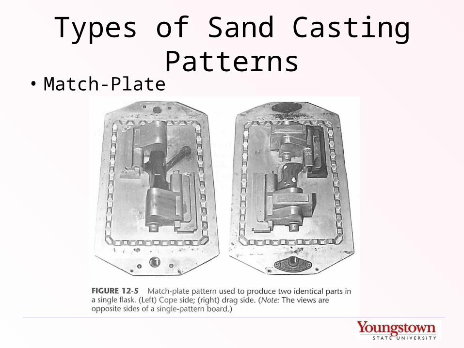
Types of Sand Casting Patterns• Match-Plate
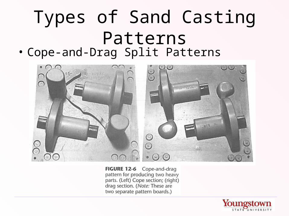
Types of Sand Casting Patterns• Cope-and-Drag Split Patterns

Types of Sand Casting Patterns• Loose Piece Pattern

Types of Sands
• Sands can be comprised of: ordinary silica (SiO2), zircon, olivine, or chromite and may be compounded with additives to meet four requirements:– Refractoriness– Cohesiveness– Permeability– Collapsibility
Green Sand
• Contains bonding agents and water
• Typical “green sand” is:– 88% silica– 9% clay– 3% water
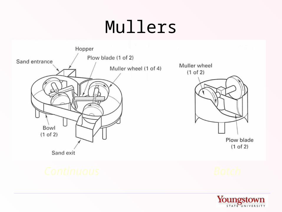
Mullers
Continuous Batch

Sand Parameters
• Grain Size – measured by sifting sand through sieves• Moisture Content – measured with moisture meter• Clay Content – measured by weighing a sample of sand
before / after washing• Permeability – AFS permeability number measured
using “standard rammed sample”• (Green) Compressive Strength – measure of mold
strength before pouring• Hardness – resistance of packed sand to penetration

Permeability Tester
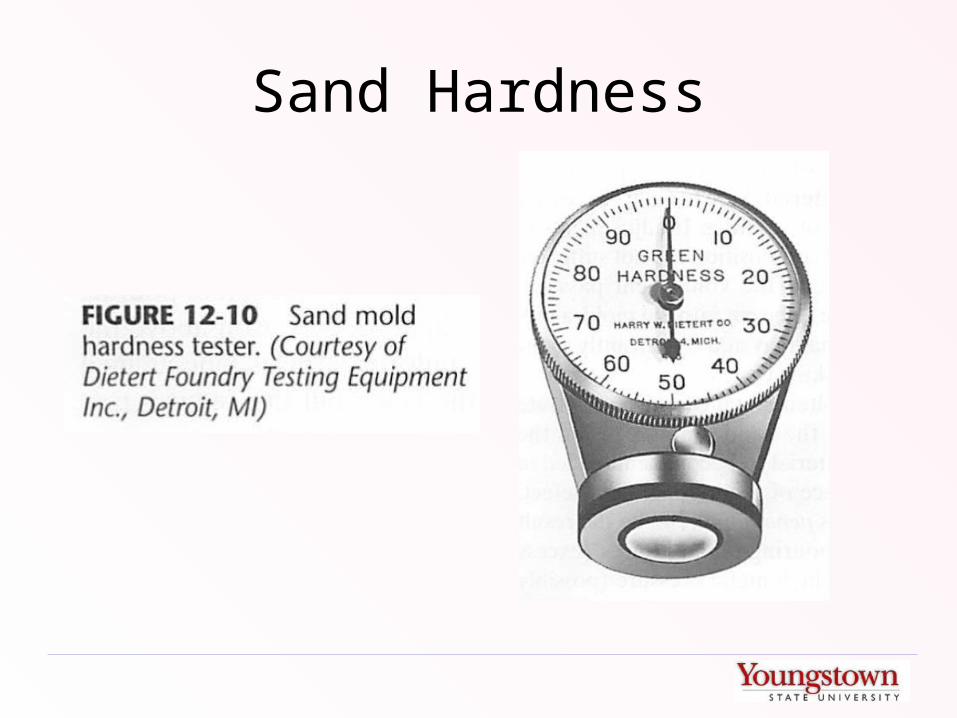
Sand Hardness

Desirable Properties of Sand-Based Molding Materials
• Inexpensive in bulk quantities• Retains properties through transportation and storage• Uniformly fills flask or container• Can be compacted or set by simple methods• Sufficient elasticity to remain undamaged during pattern removal• Can withstand high temperatures and maintain dimensional stability until
solidification• Sufficiently permeable to allow gases to escape• Sufficiently dense to prevent metal penetration• Sufficiently cohesive to prevent wash-out of mold material into the pour
stream• Chemically inert to the metal being cast• Can yield to solidification and thermal shrinkage, preventing hot tears and
cracks• Recyclable

Sand Casting Defects• Sand Expansion Defects – occur on large, flat portions of castings
where large expansion must occur in one direction. Can be alleviated by:– Careful selection of sand geometry (some sands “slide” past each other
more easily
– Use of low-expansion sands (zircon or olivine)
– Additional clay added to absorb expansion
– Volatile additives in sand mixture (burn off and create space)
• Voids or Blows – due to trapped gas and low sand permeability• Penetration – overly fluid pour traps sand particles in melt• Hot tears or cracks – high solidification shrinkage resisted by mold
with poor collapsibility
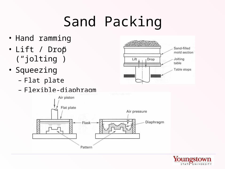
Sand Packing• Hand ramming• Lift / Drop (“jolting”)• Squeezing
– Flat plate– Flexible-diaphragm

Automatic Match Plate Molding
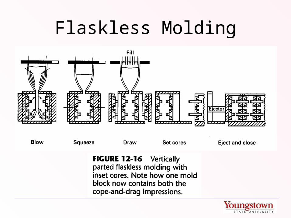
Flaskless Molding
Common-Runner Flaskless Pours
• H-process – long, horizontal runners connect multiple cavities– Large variations in fill temperature
• Stack Molding – Molds are stacked and share a common vertical sprue
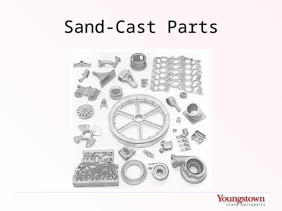
Sand-Cast Parts
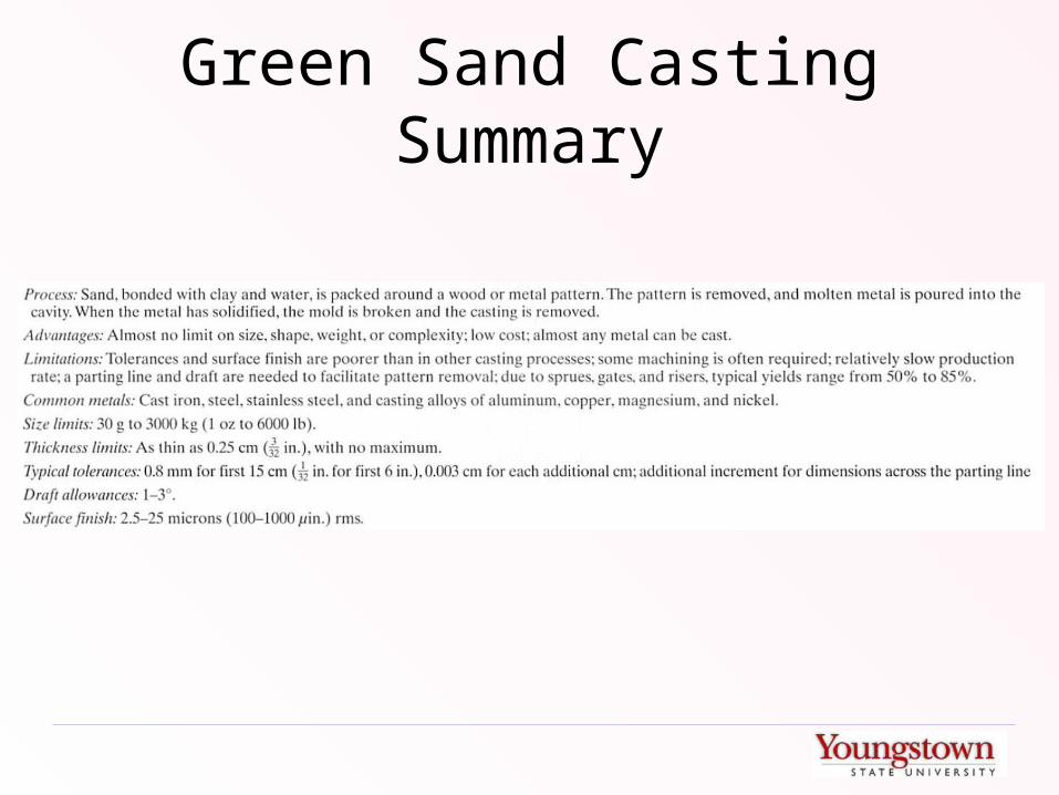
Green Sand Casting Summary
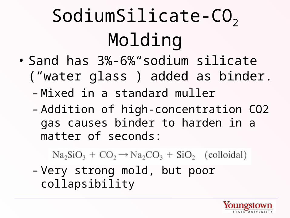
SodiumSilicate-CO2 Molding
• Sand has 3%-6% sodium silicate (“water glass”) added as binder.– Mixed in a standard muller– Addition of high-concentration CO2 gas
causes binder to harden in a matter of seconds:
– Very strong mold, but poor collapsibility
No-Bake / Air Set / Chemically Bonded Sands
• A variety of other binders that cure at room temperature can be used to hold sand together
• Provide greater mold strength than green sand.
• Added cost and time.

Shell Casting
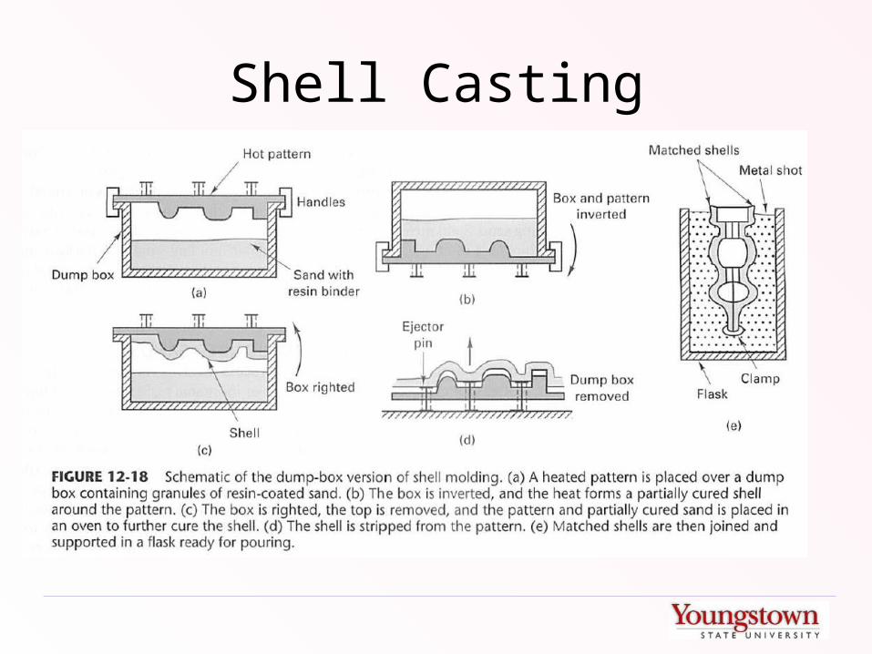
• Individual grains of sand are pre-coated with a phenolic resin and heat-sensitive liquid catalist.
• Sand spread on top of a heated (450 – 600 deg. F) metal pattern.
• Heat bonds the material near the pattern. • Excess sand is poured off.• Thin shell is removed and placed in an oven for
further curing.
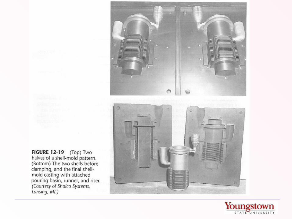
Shell Casting
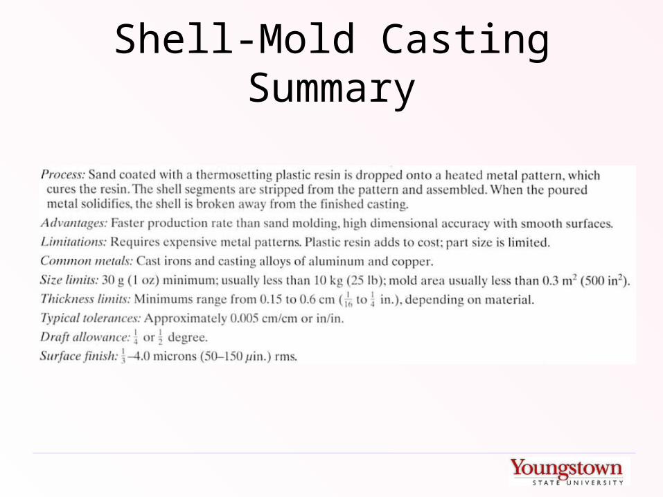
Shell-Mold Casting Summary
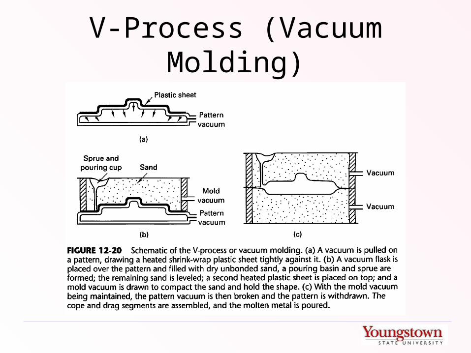
V-Process (Vacuum Molding)
Eff-Set Casting
• Wet sand with minimal clay is packed around a pattern
• Pattern is removed and surface is sprayed with liquid nitrogen to freeze surface
• Molten metal is poured while mold is still frozen.
• Low binder cost and excellent shakeout, but not being used commercially.
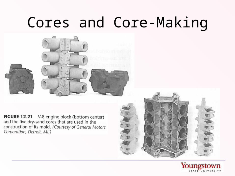
Cores and Core-Making

Cores to Make Holes
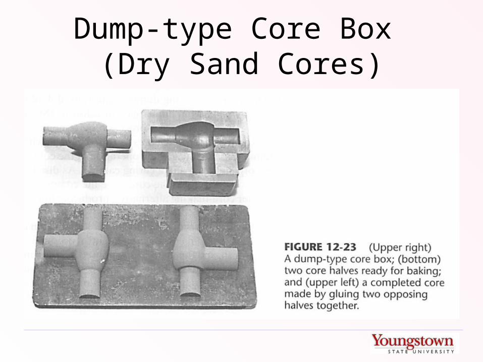
Dump-type Core Box (Dry Sand Cores)

Chaplets
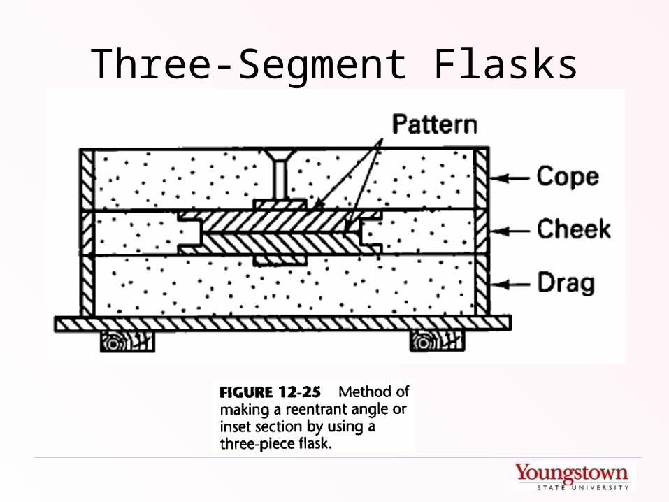
Three-Segment Flasks
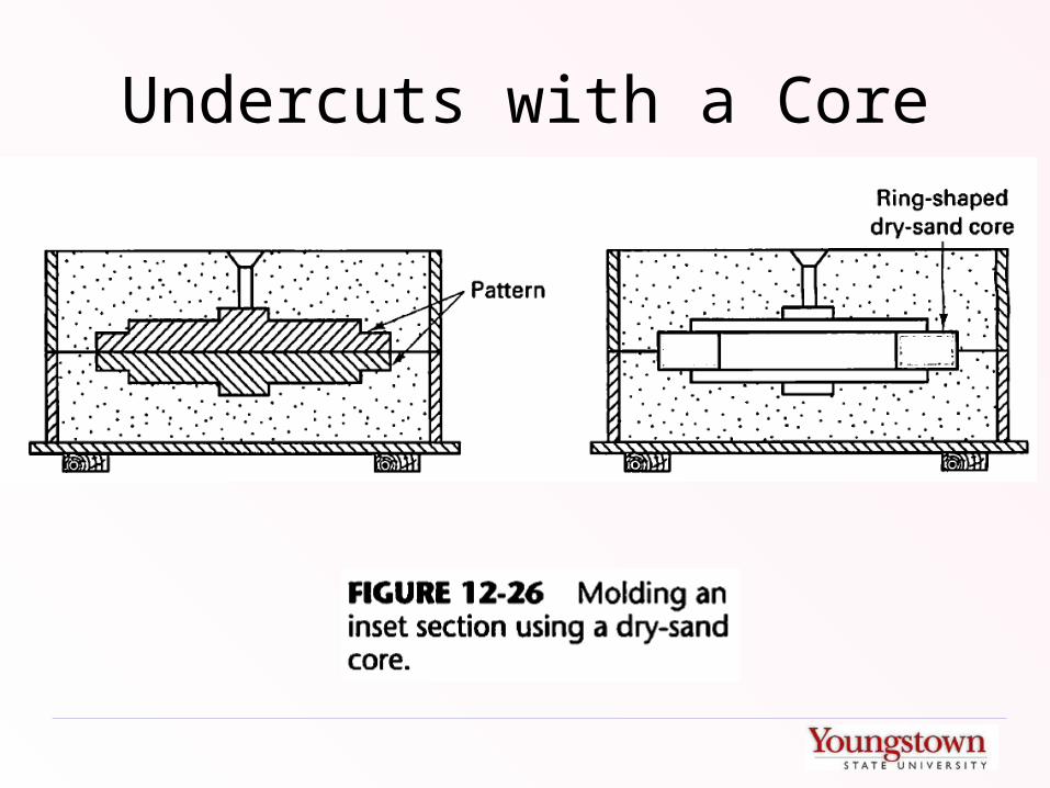
Undercuts with a Core

Plaster Casting
• Expendable Plaster Molds– Can only be used for low-melting alloys– Excellent dimensional characteristics

Antioch Process
• Variation of plaster mold casting where mold is comprised of 50% plaster and 50% sand.
• Molds are cured in an autoclave to reduce solidification time and improve permeability
• Foaming agents can be added to increase volume and permeability by 50-100%

Ceramic Mold Casting
• Similar to plaster mold casting• Ceramic material has higher temperature
resistance.• Excellent dimensional and surface finish
characteristics.• “Shaw Process” uses slurry with volatiles mixed
in. Partially set mold is “fired” with a torch to set the ceramic and create a fine network of microfractures that offer excellent permeability
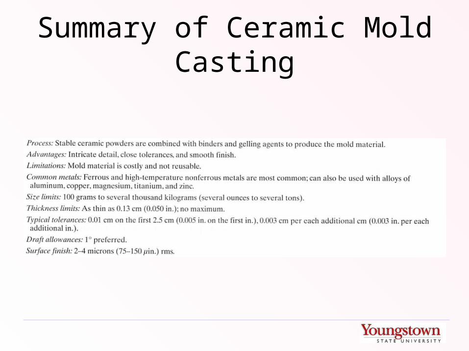
Summary of Ceramic Mold Casting

Investment Casting
Lost Foam Casting

Die Casting

Permanent Mold Casting