products and services catalog - mcgill airflo · dimensions mcgill airflow ... standard lengths of...
TRANSCRIPT
An enterprise of United McGill Corporation -Founded in 1951
One Mission ParkGroveport, Ohio 43125-1149614/836-9981, Fax: 614/836-9843E-mail: [email protected] site: http://www.mcgillairflow.com
Doub le-Wall, Round Duct and F itt ingsDimensions
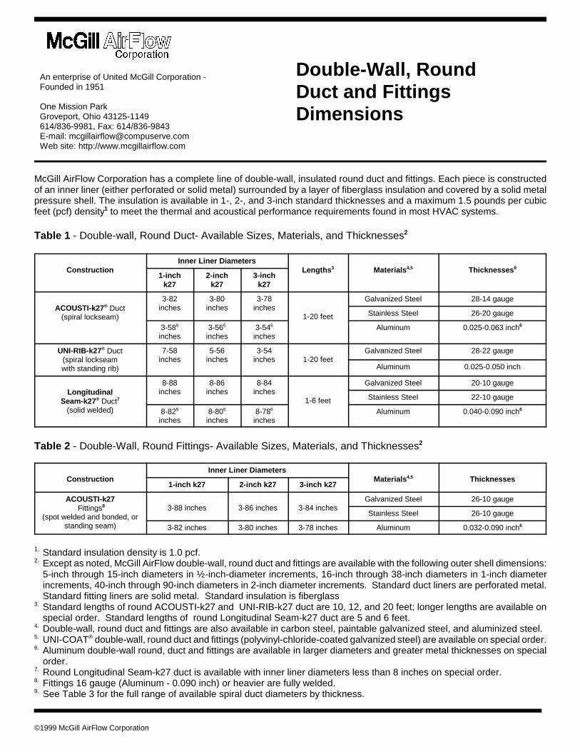
McGill AirFlow Corporation has a complete line of double-wall, insulated round duct and fittings. Each piece is constructedof an inner liner (either perforated or solid metal) surrounded by a layer of fiberglass insulation and covered by a solid metalpressure shell. The insulation is available in 1-, 2-, and 3-inch standard thicknesses and a maximum 1.5 pounds per cubicfeet (pcf) density1 to meet the thermal and acoustical performance requirements found in most HVAC systems.
Table 1 - Double-wall, Round Duct- Available Sizes, Materials, and Thicknesses2
ConstructionInner Liner Diameters
Lengths3 Materials4,5 Thicknesses 9
1-inchk27
2-inchk27
3-inchk27
ACOUSTI-k27® Duct(spiral lockseam)
3-82inches
3-80inches
3-78inches
1-20 feet
Galvanized Steel 28-14 gauge
Stainless Steel 26-20 gauge
3-586
inches3-566
inches3-546
inchesAluminum 0.025-0.063 inch6
UNI-RIB-k27® Duct(spiral lockseamwith standing rib)
7-58inches
5-56inches
3-54inches 1-20 feet
Galvanized Steel 28-22 gauge
Aluminum 0.025-0.050 inch
Long itudinalSeam-k27® Duct7
(solid welded)
8-88inches
8-86inches
8-84inches
1-6 feet
Galvanized Steel 20-10 gauge
Stainless Steel 22-10 gauge
8-826
inches8-806
inches8-786
inchesAluminum 0.040-0.090 inch6
Table 2 - Double-Wall, Round Fittings- Available Sizes, Materials, and Thicknesses2
ConstructionInner Liner Diameters
Materials4,5 Thicknesses1-inch k27 2-inch k27 3-inch k27
ACOUSTI-k27 Fittings8
(spot welded and bonded, orstanding seam)
3-88 inches 3-86 inches 3-84 inchesGalvanized Steel 26-10 gauge
Stainless Steel 26-10 gauge
3-82 inches 3-80 inches 3-78 inches Aluminum 0.032-0.090 inch6
1. Standard insulation density is 1.0 pcf.2. Except as noted, McGill AirFlow double-wall, round duct and fittings are available with the following outer shell dimensions:
5-inch through 15-inch diameters in ½-inch-diameter increments, 16-inch through 38-inch diameters in 1-inch diameterincrements, 40-inch through 90-inch diameters in 2-inch diameter increments. Standard duct liners are perforated metal.Standard fitting liners are solid metal. Standard insulation is fiberglass
3. Standard lengths of round ACOUSTI-k27 and UNI-RIB-k27 duct are 10, 12, and 20 feet; longer lengths are available onspecial order. Standard lengths of round Longitudinal Seam-k27 duct are 5 and 6 feet.
4. Double-wall, round duct and fittings are also available in carbon steel, paintable galvanized steel, and aluminized steel.5. UNI-COAT® double-wall, round duct and fittings (polyvinyl-chloride-coated galvanized steel) are available on special order.6. Aluminum double-wall round, duct and fittings are available in larger diameters and greater metal thicknesses on special
order.7. Round Longitudinal Seam-k27 duct is available with inner liner diameters less than 8 inches on special order.8. Fittings 16 gauge (Aluminum - 0.090 inch) or heavier are fully welded.9. See Table 3 for the full range of available spiral duct diameters by thickness.
©1999 McGill AirFlow Corporation
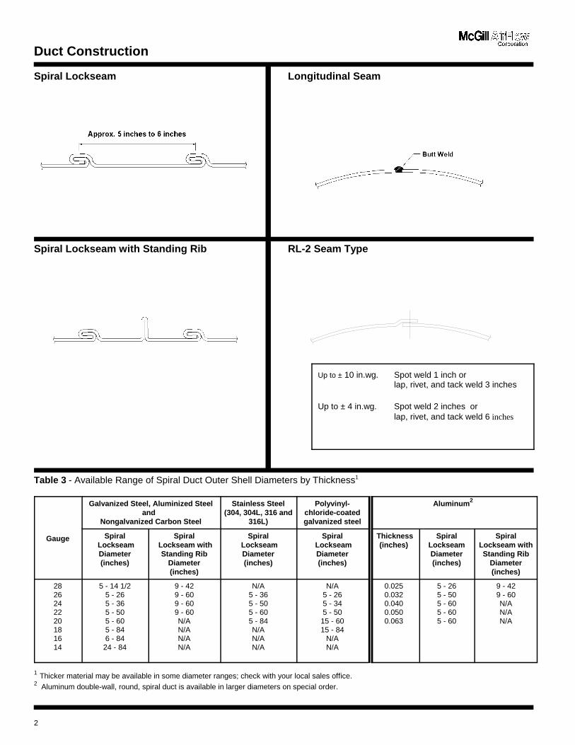
Duct Construction
Spiral Lockseam Longitudinal Seam
Spiral Lockseam with Standing Rib RL-2 Seam Type
Table 3 - Available Range of Spiral Duct Outer Shell Diameters by Thickness1
Gauge
Galvanized Steel, Aluminized Steeland
Nongalvanized Carbon Steel
Stainless Steel(304, 304L, 316 and
316L)
Polyvinyl-chloride-coatedgalvanized steel
Aluminum2
Spiral LockseamDiameter(inches)
Spiral Lockseam with
Standing RibDiameter(inches)
Spiral LockseamDiameter(inches)
Spiral LockseamDiameter(inches)
Thickness(inches)
SpiralLockseamDiameter(inches)
SpiralLockseam withStanding Rib
Diameter(inches)
2826242220181614
5 - 14 1/25 - 265 - 365 - 505 - 605 - 846 - 84
24 - 84
9 - 429 - 609 - 609 - 60N/AN/AN/AN/A
N/A5 - 365 - 505 - 605 - 84N/AN/AN/A
N/A5 - 265 - 345 - 50
15 - 6015 - 84
N/AN/A
0.0250.0320.0400.0500.063
5 - 265 - 505 - 605 - 605 - 60
9 - 429 - 60N/AN/AN/A
1 Thicker material may be available in some diameter ranges; check with your local sales office.2 Aluminum double-wall, round, spiral duct is available in larger diameters on special order.
2
Up to ± 10 in.wg. Spot weld 1 inch orlap, rivet, and tack weld 3 inches
Up to ± 4 in.wg. Spot weld 2 inches orlap, rivet, and tack weld 6 inches
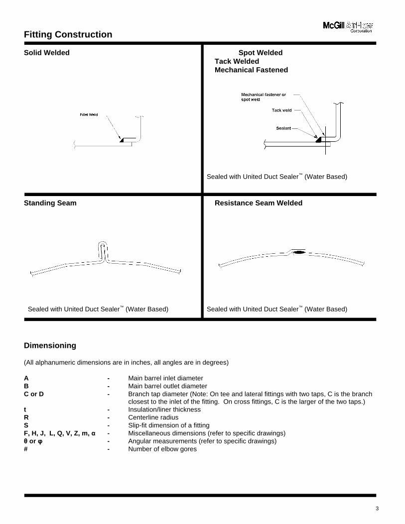
Fitting Construction
Solid Welded Spot WeldedTack WeldedMechanical Fastened
Sealed with United Duct Sealer™ (Water Based)
Standing Seam Resistance Seam Welded
Sealed with United Duct Sealer™ (Water Based) Sealed with United Duct Sealer™ (Water Based)
Dimensioning
(All alphanumeric dimensions are in inches, all angles are in degrees)
A - Main barrel inlet diameterB - Main barrel outlet diameterC or D - Branch tap diameter (Note: On tee and lateral fittings with two taps, C is the branch
closest to the inlet of the fitting. On cross fittings, C is the larger of the two taps.)t - Insulation/liner thicknessR - Centerline radiusS - Slip-fit dimension of a fittingF, H, J, L, Q, V, Z, m, . - Miscellaneous dimensions (refer to specific drawings)� or 3 - Angular measurements (refer to specific drawings)# - Number of elbow gores
3
General Notes:
• Dimensions other than diameters are held within a 1/4-inch tolerance.
• The outer shell diameter of double-wall duct and fittings is equal to the inner liner diameter plus two timesthe insulation thickness.
• Unless ordered otherwise, the inner liners and outer shells of double-wall, round fittings are sized to slip fitinto the inner liners and outer shells of double-wall, round duct.
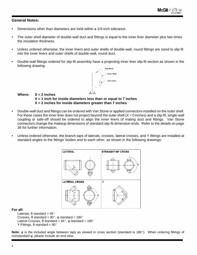
• Double-wall fittings ordered for slip-fit assembly have a projecting inner liner slip-fit section as shown in thefollowing drawing:
Where: S = 2 inchesX = 1 inch for inside diameters less than or equal to 7 inchesX = 2 inches for inside diameters greater than 7 inches
• Double-wall duct and fittings can be ordered with Van Stone or applied connectors installed on the outer shell.For these cases the inner liner does not project beyond the outer shell (X = 0 inches) and a slip-fit, single-wallcoupling or safe-off should be ordered to align the inner liners of mating duct and fittings. Van Stoneconnectors change the makeup dimensions of standard slip-fit dimension ends. Refer to the details on page36 for further information.
• Unless ordered otherwise, the branch taps of laterals, crosses, lateral crosses, and Y-fittings are installed atstandard angles to the fittings' bodies and to each other, as shown in the following drawings:
For all :Laterals, � standard = 45(Crosses, � standard = 90(, 3 standard = 180(Lateral Crosses, � standard = 45(, 3 standard = 180(Y-Fittings, � standard = 90(
Note: 3 is the included angle between taps as viewed in cross section (standard is 180(). When ordering fittings ofnonstandard 3, please include an end view.
4
General Notes:
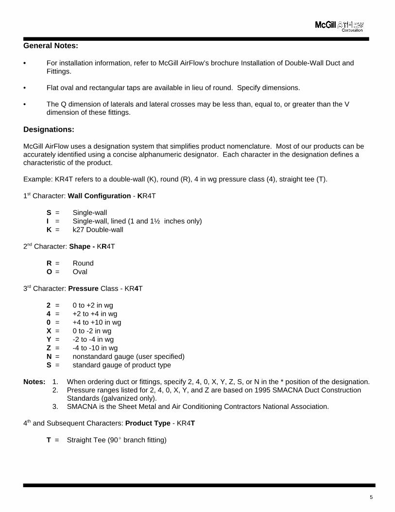
• For installation information, refer to McGill AirFlow’s brochure Installation of Double-Wall Duct andFittings.
• Flat oval and rectangular taps are available in lieu of round. Specify dimensions.
• The Q dimension of laterals and lateral crosses may be less than, equal to, or greater than the Vdimension of these fittings.
Designations:
McGill AirFlow uses a designation system that simplifies product nomenclature. Most of our products can beaccurately identified using a concise alphanumeric designator. Each character in the designation defines acharacteristic of the product.
Example: KR4T refers to a double-wall (K), round (R), 4 in wg pressure class (4), straight tee (T).
1st Character: Wall Configuration - KR4T
S = Single-wallI = Single-wall, lined (1 and 1½ inches only)K = k27 Double-wall
2nd Character: Shape - KR4T
R = RoundO = Oval
3rd Character: Pressure Class - KR4T
2 = 0 to +2 in wg4 = +2 to +4 in wg0 = +4 to +10 in wgX = 0 to -2 in wgY = -2 to -4 in wgZ = -4 to -10 in wgN = nonstandard gauge (user specified)S = standard gauge of product type
Notes: 1. When ordering duct or fittings, specify 2, 4, 0, X, Y, Z, S, or N in the * position of the designation. 2. Pressure ranges listed for 2, 4, 0, X, Y, and Z are based on 1995 SMACNA Duct Construction
Standards (galvanized only). 3. SMACNA is the Sheet Metal and Air Conditioning Contractors National Association.
4th and Subsequent Characters: Produ ct Type - KR4T
T = Straight Tee (90( branch fitting)
5
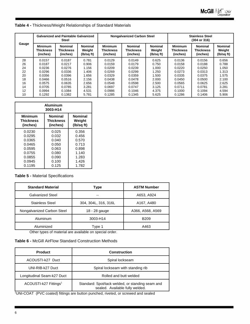
Table 4 - Thickness/Weight Relationships of Standard Materials
Gauge
Galvanized and Paintable GalvanizedSteel
Nongalvanized Carbon Steel Stainless Steel(304 or 316)
MinimumThickness(inches)
NominalThickness(inches)
NominalWeight
(lb/sq ft)
MinimumThickness(inches)
NominalThickness(inches)
NominalWeight
(lb/sq ft)
MinimumThickness(inches)
NominalThickness(inches)
NominalWeight
(lb/sq ft)
28262422201816141210
0.01570.01870.02360.02960.03560.04660.05750.07050.09940.1292
0.01870.02170.02760.03360.03960.05160.06350.07850.10840.1382
0.7810.9061.1561.4061.6562.1562.6563.2814.5315.781
0.01290.01590.02090.02690.03290.04380.05480.06970.09860.1285
0.01490.01790.02390.02990.03590.04780.05980.07470.10460.1345
0.6250.7501.0001.2501.5002.0002.5003.1254.3755.625
0.01360.01580.02200.02730.03350.04500.05650.07110.10000.1286
0.01560.01880.02500.03130.03750.05000.06250.07810.10940.1406
0.6560.7881.0501.3131.5752.1002.6253.2814.5945.906
Aluminum3003-H14
MinimumThickness(inches)
NominalThickness(inches)
NominalWeight
(lb/sq ft)
0.02300.02950.03650.04650.05950.07550.08550.09450.1195
0.0250.0320.0400.0500.0630.0800.0900.1000.125
0.3560.4560.5700.7130.8981.1401.2831.4261.782
Table 5 - Material Specifications
Standard Material Type ASTM Number
Galvanized Steel -- A653, A924
Stainless Steel 304, 304L, 316, 316L A167, A480
Nongalvanized Carbon Steel 18 - 28 gauge A366, A568, A569
Aluminum 3003-H14 B209
Aluminized Type 1 A463
Other types of material are available on special order.
Table 6 - McGill AirFlow Standard Construction Methods
Product Construction
ACOUSTI-k27 Duct Spiral lockseam
UNI-RIB-k27 Duct Spiral lockseam with standing rib
Longitudinal Seam-k27 Duct Rolled and butt welded
ACOUSTI-k27 Fittings1 Standard: Spot/tack welded, or standing seam andsealed. Available fully welded.
1UNI-COAT (PVC coated) fittings are button punched, riveted, or screwed and sealed
6
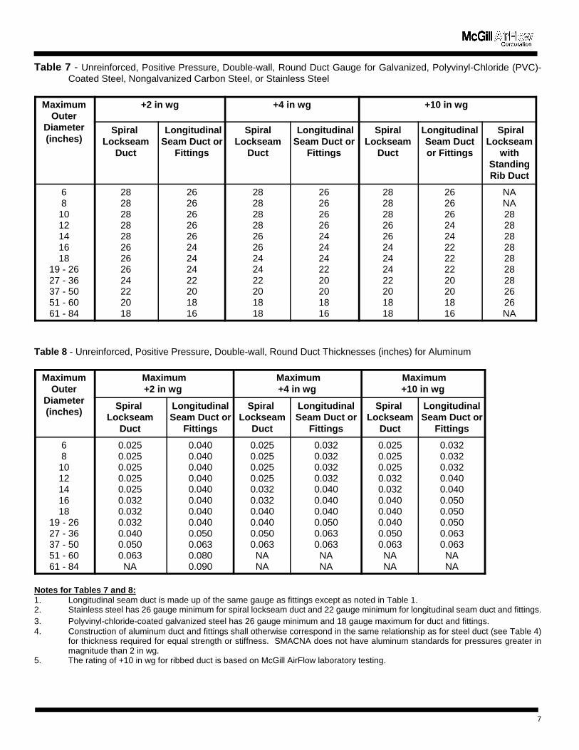
Table 7 - Unreinforced, Positive Pressure, Double-wall, Round Duct Gauge for Galvanized, Polyvinyl-Chloride (PVC)-Coated Steel, Nongalvanized Carbon Steel, or Stainless Steel
MaximumOuter
Diameter(inches)
+2 in wg +4 in wg +10 in wg
Spiral Lockseam
Duct
LongitudinalSeam Duct or
Fittings
SpiralLockseam
Duct
LongitudinalSeam Duct or
Fittings
SpiralLockseam
Duct
LongitudinalSeam Ductor Fittings
SpiralLockseam
withStandingRib Duct
681012141618
19 - 2627 - 3637 - 5051 - 6061 - 84
282828282826262624222018
262626262624242422201816
282828282626242422201818
262626262424242220201816
282828262624242422201818
262626242422222220201816
NANA282828282828282626NA
Table 8 - Unreinforced, Positive Pressure, Double-wall, Round Duct Thicknesses (inches) for Aluminum
MaximumOuter
Diameter(inches)
Maximum+2 in wg
Maximum+4 in wg
Maximum+10 in wg
Spiral Lockseam
Duct
LongitudinalSeam Duct or
Fittings
Spiral Lockseam
Duct
LongitudinalSeam Duct or
Fittings
Spiral Lockseam
Duct
LongitudinalSeam Duct or
Fittings
681012141618
19 - 2627 - 3637 - 5051 - 6061 - 84
0.0250.0250.0250.0250.0250.0320.0320.0320.0400.0500.063NA
0.0400.0400.0400.0400.0400.0400.0400.0400.0500.0630.0800.090
0.0250.0250.0250.0250.0320.0320.0400.0400.0500.063NANA
0.0320.0320.0320.0320.0400.0400.0400.0500.0630.063NANA
0.0250.0250.0250.0320.0320.0400.0400.0400.0500.063NANA
0.0320.0320.0320.0400.0400.0500.0500.0500.0630.063NANA
Notes for Tables 7 and 8:1. Longitudinal seam duct is made up of the same gauge as fittings except as noted in Table 1.2. Stainless steel has 26 gauge minimum for spiral lockseam duct and 22 gauge minimum for longitudinal seam duct and fittings.3. Polyvinyl-chloride-coated galvanized steel has 26 gauge minimum and 18 gauge maximum for duct and fittings. 4. Construction of aluminum duct and fittings shall otherwise correspond in the same relationship as for steel duct (see Table 4)
for thickness required for equal strength or stiffness. SMACNA does not have aluminum standards for pressures greater inmagnitude than 2 in wg.
5. The rating of +10 in wg for ribbed duct is based on McGill AirFlow laboratory testing.
7
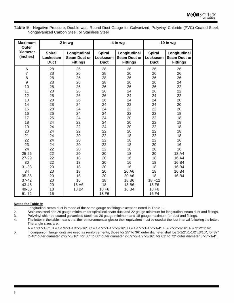
Table 9 - Negative Pressure, Double-wall, Round Duct Gauge for Galvanized, Polyvinyl-Chloride (PVC)-Coated Steel,Nongalvanized Carbon Steel, or Stainless Steel
MaximumOuter
Diameter(inches)
-2 in wg -4 in wg -10 in wg
Spiral Lockseam
Duct
LongitudinalSeam Duct or
Fittings
Spiral Lockseam
Duct
LongitudinalSeam Duct or
Fittings
Spiral Lockseam
Duct
LongitudinalSeam Duct or
Fittings
6789101112131415161718192021222324
25-2627-29
3031-33
3435-3637-4243-4849-6061-72
2828282828282828282826262424242424242222222220202020201816
2626262626262626242424242222222020202020181818181616
18 A618 B4
282828282626262624242424242422222222222020202020201818
18 F618 F6
2626262626242424222222202020201818181818161616
20 A620 A618 B618 B616 B4
26262626262624242422222222222222222020201818181818
18 F1218 F618 F616 F4
26262624222222202020181818181818161616
18 A416 A416 B416 B416 B416 B4
Notes for Table 9:1. Longitudinal seam duct is made of the same gauge as fittings except as noted in Table 1.2. Stainless steel has 26 gauge minimum for spiral lockseam duct and 22 gauge minimum for longitudinal seam duct and fittings.3. Polyvinyl-chloride-coated galvanized steel has 26 gauge minimum and 18 gauge maximum for duct and fittings. 4. The letter in the table means that the reinforcement angles or their equivalent must be used at the foot interval following the letter.
The angle sizes are:A = 1"x1"x1/8"; B = 1-1/4"x1-1/4"x3/16"; C = 1-1/2"x1-1/2"x3/16"; D = 1-1/2"x1-1/2"x1/4"; E = 2"x2"x3/16"; F = 2"x2"x1/4".
5. If companion flange joints are used as reinforcements, those for 25" to 36" outer diameter shall be 1-1/2"x1-1/2"x3/16"; for 37"to 48" outer diameter 2"x2"x3/16"; for 50" to 60" outer diameter 2-1/2"x2-1/2"x3/16"; for 61" to 72" outer diameter 3"x3"x1/4".
8
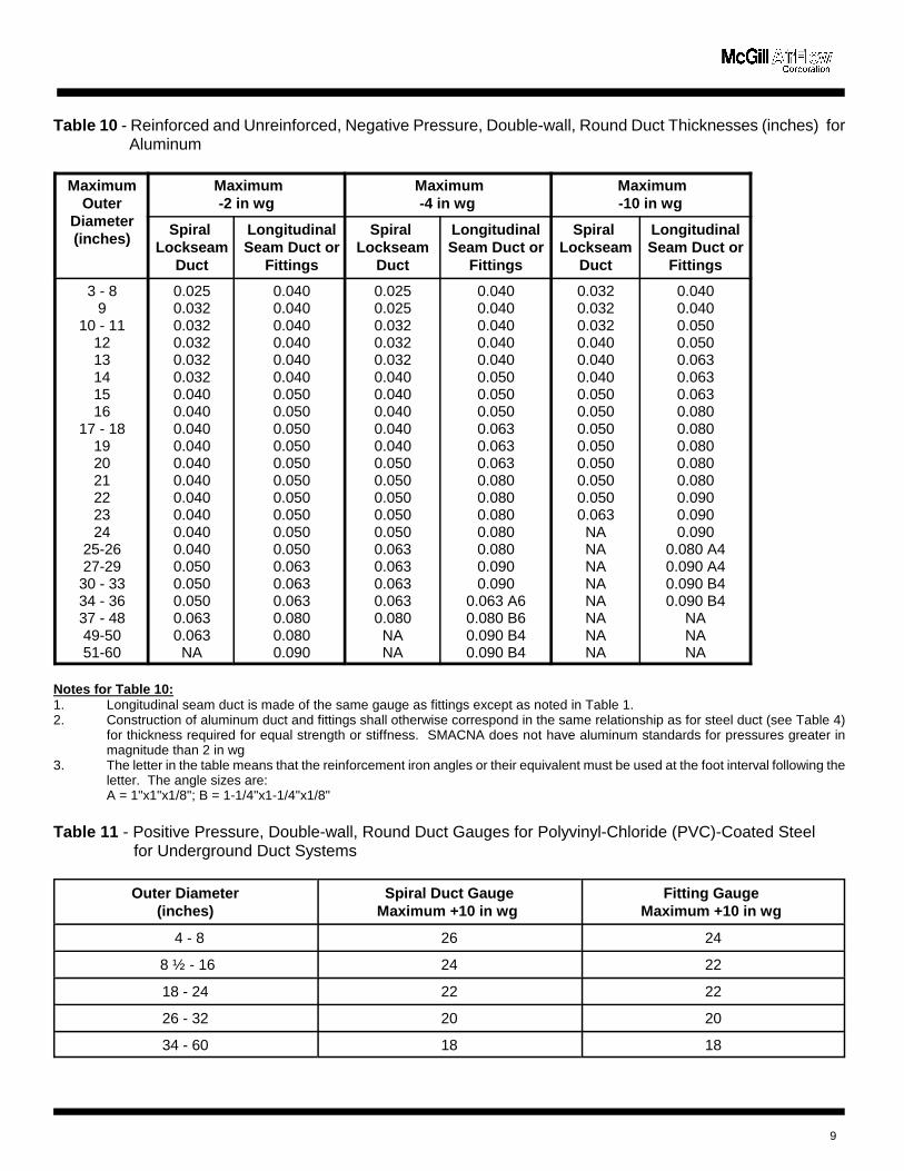
Table 10 - Reinforced and Unreinforced, Negative Pressure, Double-wall, Round Duct Thicknesses (inches) for Aluminum
MaximumOuter
Diameter(inches)
Maximum-2 in wg
Maximum-4 in wg
Maximum-10 in wg
Spiral Lockseam
Duct
LongitudinalSeam Duct or
Fittings
Spiral Lockseam
Duct
LongitudinalSeam Duct or
Fittings
Spiral Lockseam
Duct
LongitudinalSeam Duct or
Fittings
3 - 89
10 - 111213141516
17 - 18192021222324
25-2627-2930 - 3334 - 3637 - 4849-5051-60
0.0250.0320.0320.0320.0320.0320.0400.0400.0400.0400.0400.0400.0400.0400.0400.0400.0500.0500.0500.0630.063NA
0.0400.0400.0400.0400.0400.0400.0500.0500.0500.0500.0500.0500.0500.0500.0500.0500.0630.0630.0630.0800.0800.090
0.0250.0250.0320.0320.0320.0400.0400.0400.0400.0400.0500.0500.0500.0500.0500.0630.0630.0630.0630.080NANA
0.0400.0400.0400.0400.0400.0500.0500.0500.0630.0630.0630.0800.0800.0800.0800.0800.0900.090
0.063 A60.080 B60.090 B40.090 B4
0.0320.0320.0320.0400.0400.0400.0500.0500.0500.0500.0500.0500.0500.063NANANANANANANANA
0.0400.0400.0500.0500.0630.0630.0630.0800.0800.0800.0800.0800.0900.0900.090
0.080 A40.090 A40.090 B40.090 B4
NANANA
Notes for Table 10:1. Longitudinal seam duct is made of the same gauge as fittings except as noted in Table 1.2. Construction of aluminum duct and fittings shall otherwise correspond in the same relationship as for steel duct (see Table 4)
for thickness required for equal strength or stiffness. SMACNA does not have aluminum standards for pressures greater inmagnitude than 2 in wg
3. The letter in the table means that the reinforcement iron angles or their equivalent must be used at the foot interval following theletter. The angle sizes are:A = 1"x1"x1/8"; B = 1-1/4"x1-1/4"x1/8"
Table 11 - Positive Pressure, Double-wall, Round Duct Gauges for Polyvinyl-Chloride (PVC)-Coated Steel for Underground Duct Systems
Outer Diameter(inches)
Spiral Duct GaugeMaximum +10 in wg
Fitting Gauge Maximum +10 in wg
4 - 8 26 24
8 ½ - 16 24 22
18 - 24 22 22
26 - 32 20 20
34 - 60 18 18
9
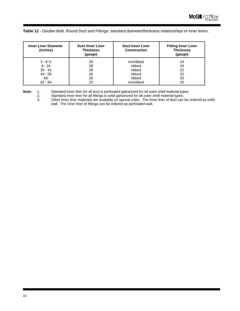
Table 12 - Double-Wall, Round Duct and Fittings: standard diameter/thickness relationships of inner liners.
Inner Liner Diameter (inches)
Duct Inner LinerThickness
(gauge)
Duct Inner LinerConstruction
Fitting Inner LinerThickness
(gauge)
3 - 8 ½9 - 34
35 - 4244 - 58
6062 - 84
282828262622
nonribbedribbedribbedribbedribbed
nonribbed
242422222020
Note: 1. Standard inner liner for all duct is perforated galvanized for all outer shell material types.2. Standard inner liner for all fittings is solid galvanized for all outer shell material types.3. Other inner liner materials are available on special order. The inner liner of duct can be ordered as solid
wall. The inner liner of fittings can be ordered as perforated wall.
10
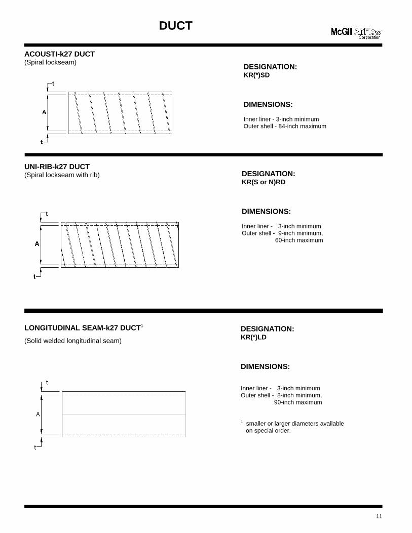
DESIGNATION:KR(*)SD
DIMENSIONS:
Inner liner - 3-inch minimumOuter shell - 84-inch maximum
DESIGNATION:KR(S or N)RD
DIMENSIONS:
Inner liner - 3-inch minimumOuter shell - 9-inch minimum,
60-inch maximum
DESIGNATION:KR(*)LD
DIMENSIONS:
Inner liner - 3-inch minimumOuter shell - 8-inch minimum,
90-inch maximum
1 smaller or larger diameters available on special order.
DUCT
ACOUSTI-k27 DUCT(Spiral lockseam)
UNI-RIB-k27 DUCT(Spiral lockseam with rib)
LONGITUDINAL SEAM-k27 DUCT1
(Solid welded longitudinal seam)
11
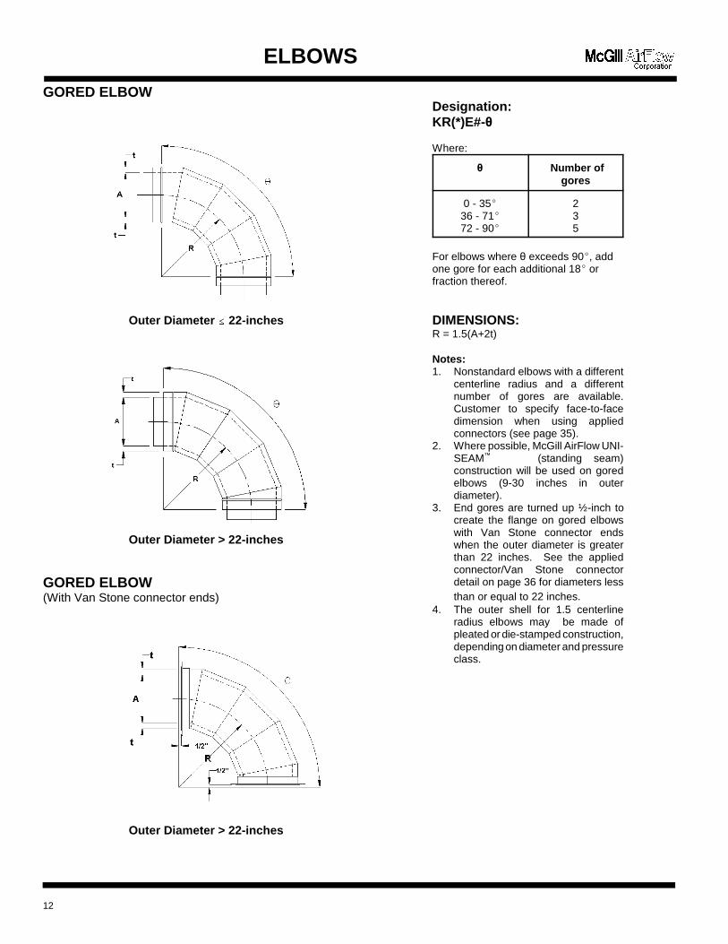
Designation:KR(*)E#-�
Where:
� Number ofgores
0 - 35(36 - 71(72 - 90(
235
For elbows where � exceeds 90(, addone gore for each additional 18( orfraction thereof.
DIMENSIONS:R = 1.5(A+2t)
Notes: 1. Nonstandard elbows with a different
centerline radius and a differentnumber of gores are available.Customer to specify face-to-facedimension when using appliedconnectors (see page 35).
2. Where possible, McGill AirFlow UNI-SEAM™ (standing seam)construction will be used on goredelbows (9-30 inches in outerdiameter).
3. End gores are turned up ½-inch tocreate the flange on gored elbowswith Van Stone connector endswhen the outer diameter is greaterthan 22 inches. See the appliedconnector/Van Stone connectordetail on page 36 for diameters lessthan or equal to 22 inches.
4. The outer shell for 1.5 centerlineradius elbows may be made ofpleated or die-stamped construction,depending on diameter and pressureclass.
ELBOWS
GORED ELBOW
Outer Diameter �� 22-inches
Outer Diameter > 22-inches
GORED ELBOW(With Van Stone connector ends)
Outer Diameter > 22-inches
12
ELBOWS
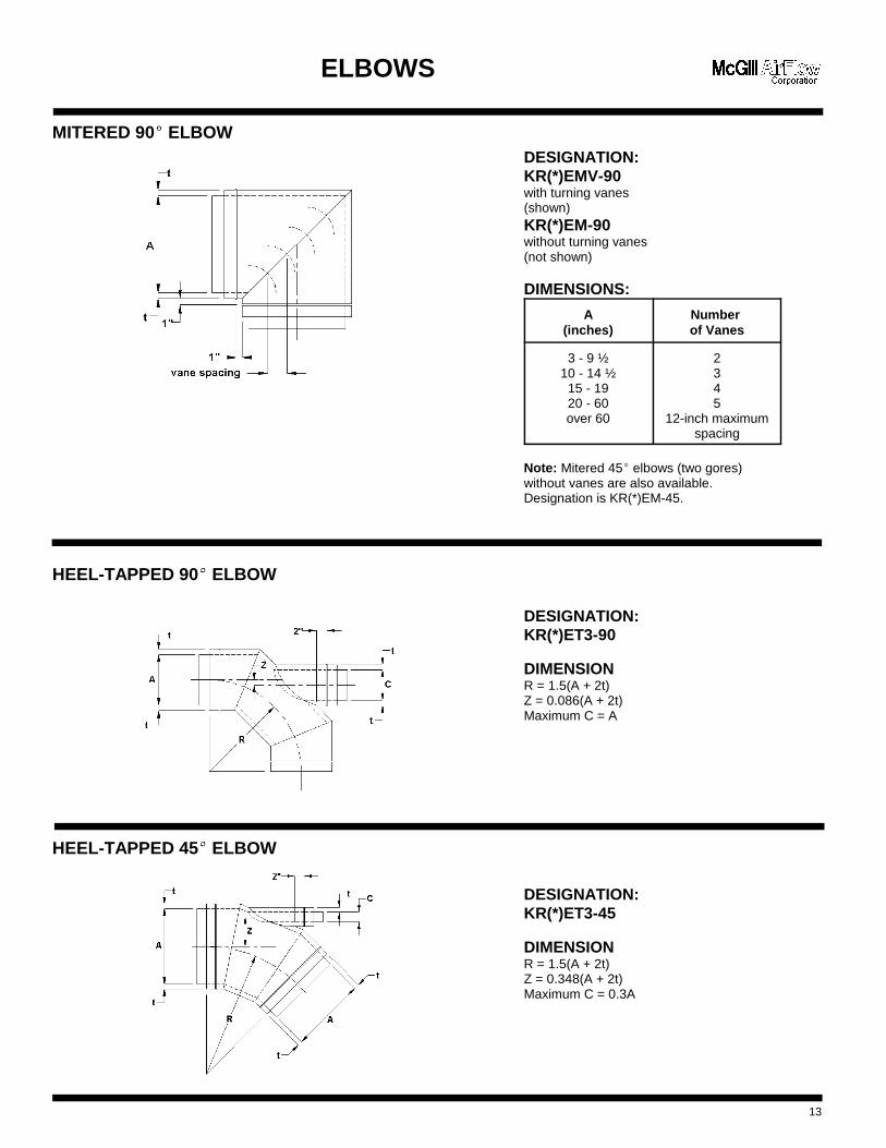
MITERED 90(�
ELBOW
HEEL-TAPPED 90(�
ELBOW
HEEL-TAPPED 45(�
ELBOW
13
DESIGNATION:KR(*)EMV-90with turning vanes(shown)KR(*)EM-90without turning vanes(not shown)
DIMENSIONS:
A(inches)
Number of Vanes
3 - 9 ½10 - 14 ½
15 - 1920 - 60over 60
2345
12-inch maximumspacing
Note: Mitered 45( elbows (two gores)without vanes are also available. Designation is KR(*)EM-45.
DESIGNATION:KR(*)ET3-90
DIMENSIONR = 1.5(A + 2t)Z = 0.086(A + 2t)Maximum C = A
DESIGNATION:KR(*)ET3-45
DIMENSIONR = 1.5(A + 2t)Z = 0.348(A + 2t)Maximum C = 0.3A
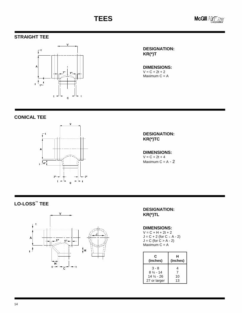
DESIGNATION:KR(*)T
DIMENSIONS:V = C + 2t + 2Maximum C = A
DESIGNATION:KR(*)TC
DIMENSIONS:V = C + 2t + 4Maximum C = A - 2
DESIGNATION:KR(*)TL
DIMENSIONS:V = C + H + 2t + 2J = C + 2 (for C � A - 2)J = C (for C > A - 2)Maximum C = A
C(inches)
H(inches)
3 - 88 ½ - 14
14 ½ - 2627 or larger
47
1013
TEES
STRAIGHT TEE
CONICAL TEE
LO-LOSS™ TEE
14
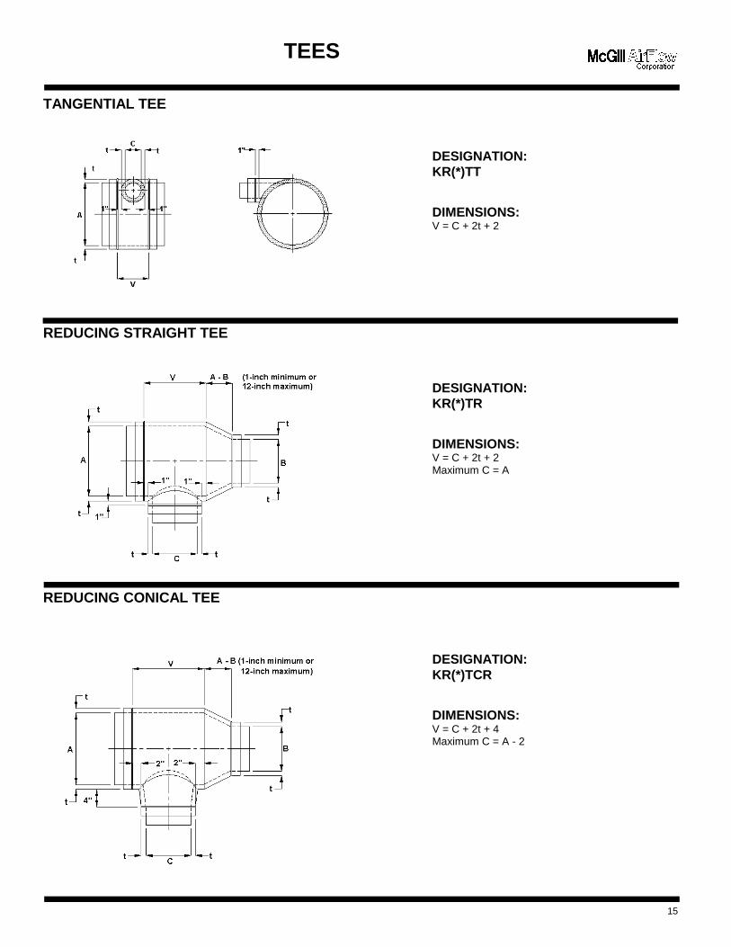
DESIGNATION:KR(*)TT
DIMENSIONS:V = C + 2t + 2
DESIGNATION:KR(*)TR
DIMENSIONS:V = C + 2t + 2Maximum C = A
DESIGNATION:KR(*)TCR
DIMENSIONS:V = C + 2t + 4Maximum C = A - 2
TEES
TANGENTIAL TEE
REDUCING STRAIGHT TEE
REDUCING CONICAL TEE
15
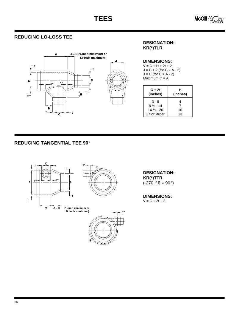
DESIGNATION:KR(*)TLR
DIMENSIONS:V = C + H + 2t + 2J = C + 2 (for C � A - 2)J = C (for C > A - 2)Maximum C = A
C + 2t(inches)
H(inches)
3 - 88 ½ - 14
14 ½ - 2627 or larger
47
1013
DESIGNATION:KR(*)TTR(-270 if � g 90()
DIMENSIONS:V = C + 2t + 2
TEES
REDUCING LO-LOSS TEE
REDUCING TANGENTIAL TEE 90(�
16
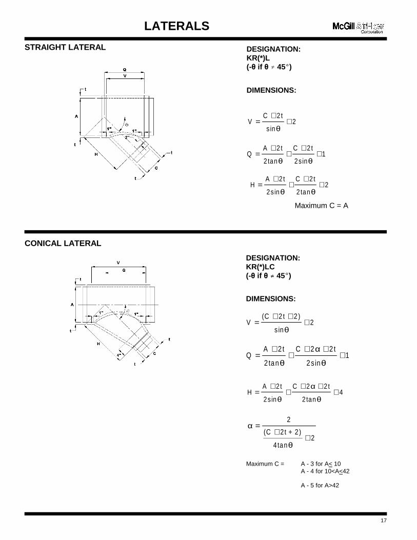
VC 2t
s in2=
++
θ
QA 2t
2 tan
C 2 t
2s in1=
++
++
θ θ
HA 2t
2s in
C 2 t
2 tan2=
++
++
θ θ
LATERALS
STRAIGHT LATERAL
Maximum C = A
CONICAL LATERAL
Maximum C = A - 3 for A< 10A - 4 for 10<A<42
A - 5 for A>42
17
DESIGNATION:KR(*)L(-� if � g� 45(
�)
DIMENSIONS:
HA 2t
2s in
C 2 t
2 tan4=
++
+ ++
θ
α
θ
2
V(C 2 t 2 )
s in2=
+ ++
θ
QA 2t
2 tan
C 2 2 t
2s in1=
++
+ ++
θ
α
θ
α
θ
=+
+
2
(C 2t + 2)
4 tan2
DESIGNATION:KR(*)LC(-� if � g� 45(
�)
DIMENSIONS:
VC 2t
s in2=
++
θ
QA 2t
2 tan
C 2 t
2s in1=
++
++
θ θ
HA 2t
2s in
C 2 t
2 tan2=
++
++
θ θ
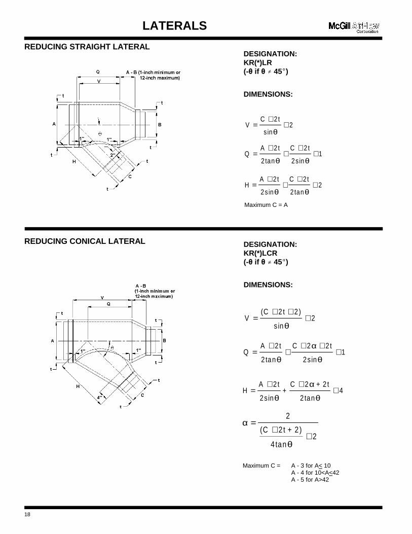
QA 2t
2 tan
C 2 2 t
2s in1=
++
+ ++
θ
α
θ
V(C 2t 2 )
s in2=
+ ++
θ
HA 2t
2s in+
C 2 + 2 t
2 tan4=
+ ++
θ
α
θ
α
θ
=+
+
2
(C 2 t + 2)
4 tan2
LATERALS
REDUCING STRAIGHT LATERAL
Maximum C = A
REDUCING CONICAL LATERAL
Maximum C = A - 3 for A< 10A - 4 for 10<A<42A - 5 for A>42
18
DESIGNATION:KR(*)LR(-� if � g� 45(
�)
DIMENSIONS:
DESIGNATION:KR(*)LCR(-� if � g� 45(
�)
DIMENSIONS:
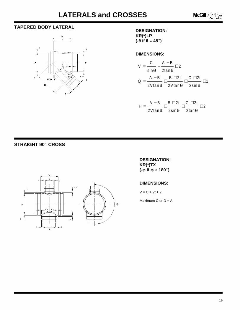
QA B
2V tan
B 2t
2V tan
C 2t
2s in1=
−+
++
++
θ θ θ
VC
sin
A B
2tan2= −
−+
θ θ
HA B
2V tan
B 2t
2s in
C 2t
2 tan2=
−+
++
++
θ θ θ
DESIGNATION:KR(*)LP(-� if � g� 45(
�)
DIMENSIONS:
DESIGNATION:KR(*)TX(-3 if 3 g� 180(
�)
DIMENSIONS:
V = C + 2t + 2
Maximum C or D = A
LATERALS and CROSSES
TAPERED BODY LATERAL
STRAIGHT 90(� CROSS
19
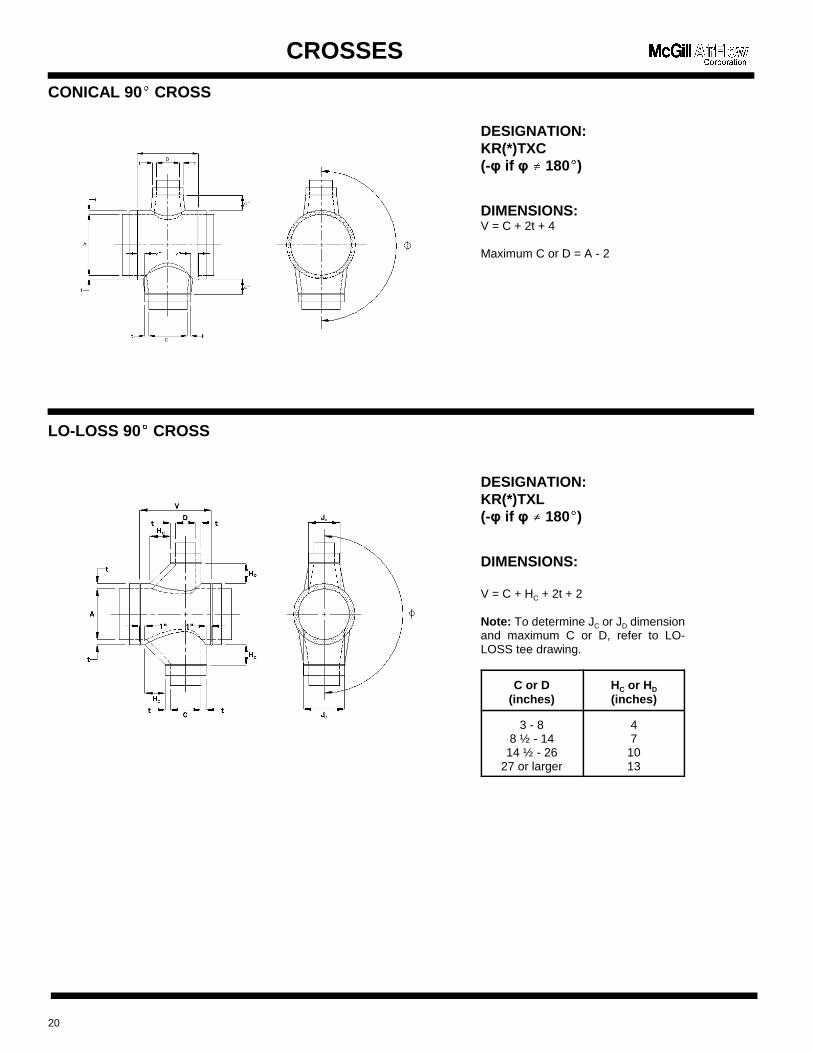
DESIGNATION:KR(*)TXC(-3 if 3 g� 180(
�)
DIMENSIONS:V = C + 2t + 4
Maximum C or D = A - 2
DESIGNATION:KR(*)TXL(-3 if 3 g� 180(
�)
DIMENSIONS:
V = C + HC + 2t + 2
Note: To determine JC or JD dimensionand maximum C or D, refer to LO-LOSS tee drawing.
C or D(inches)
HC or HD
(inches)
3 - 88 ½ - 14
14 ½ - 2627 or larger
47
1013
CROSSES
CONICAL 90(� CROSS
LO-LOSS 90(� CROSS
20
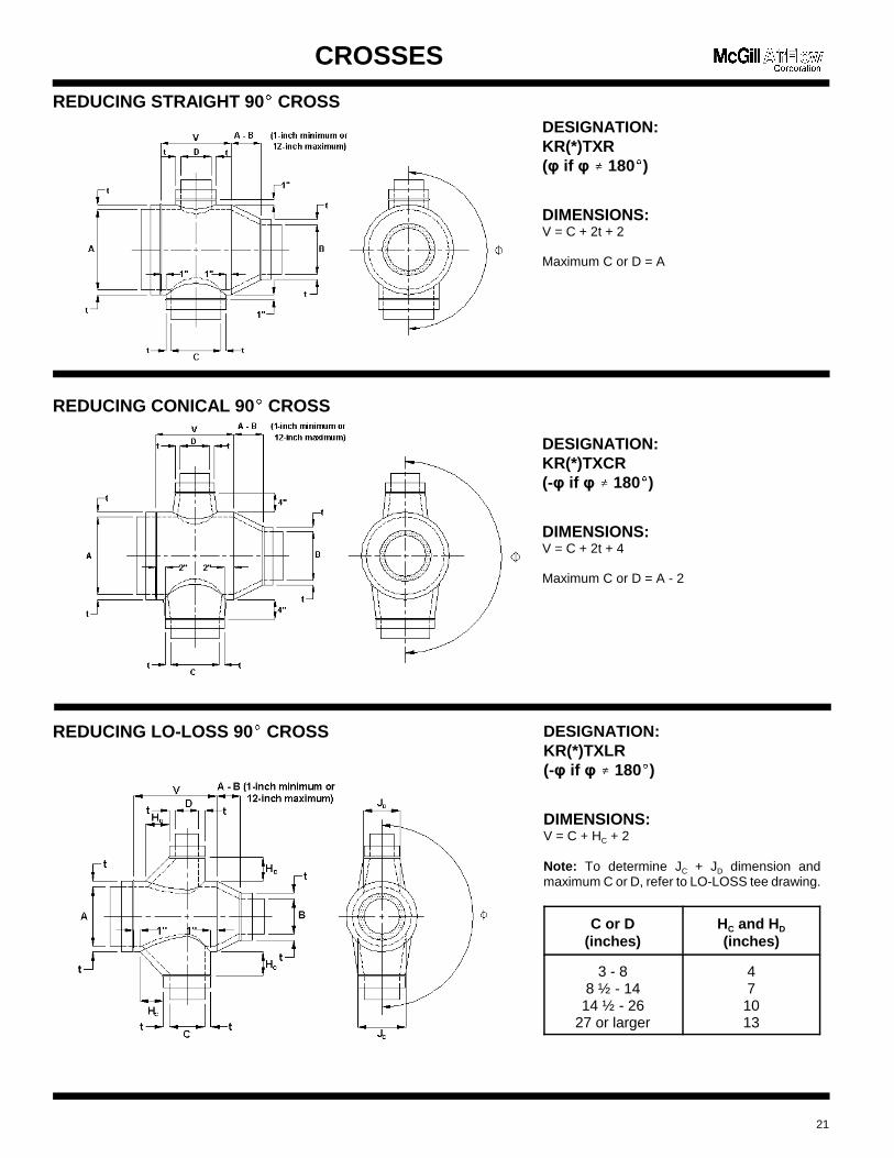
DESIGNATION:KR(*)TXR(3 if 3 g� 180(
�)
DIMENSIONS:V = C + 2t + 2
Maximum C or D = A
DESIGNATION:KR(*)TXCR(-3 if 3 g� 180(
�)
DIMENSIONS:V = C + 2t + 4
Maximum C or D = A - 2
CROSSES
REDUCING STRAIGHT 90(� CROSS
REDUCING CONICAL 90(� CROSS
REDUCING LO-LOSS 90(� CROSS
21
DESIGNATION:KR(*)TXLR(-3 if 3 g� 180(
�)
DIMENSIONS:V = C + HC + 2
Note: To determine JC + JD dimension andmaximum C or D, refer to LO-LOSS tee drawing.
C or D(inches)
HC and HD
(inches)
3 - 88 ½ - 1414 ½ - 26
27 or larger
471013
CROSSES AND END CAP
LATERAL CROSS
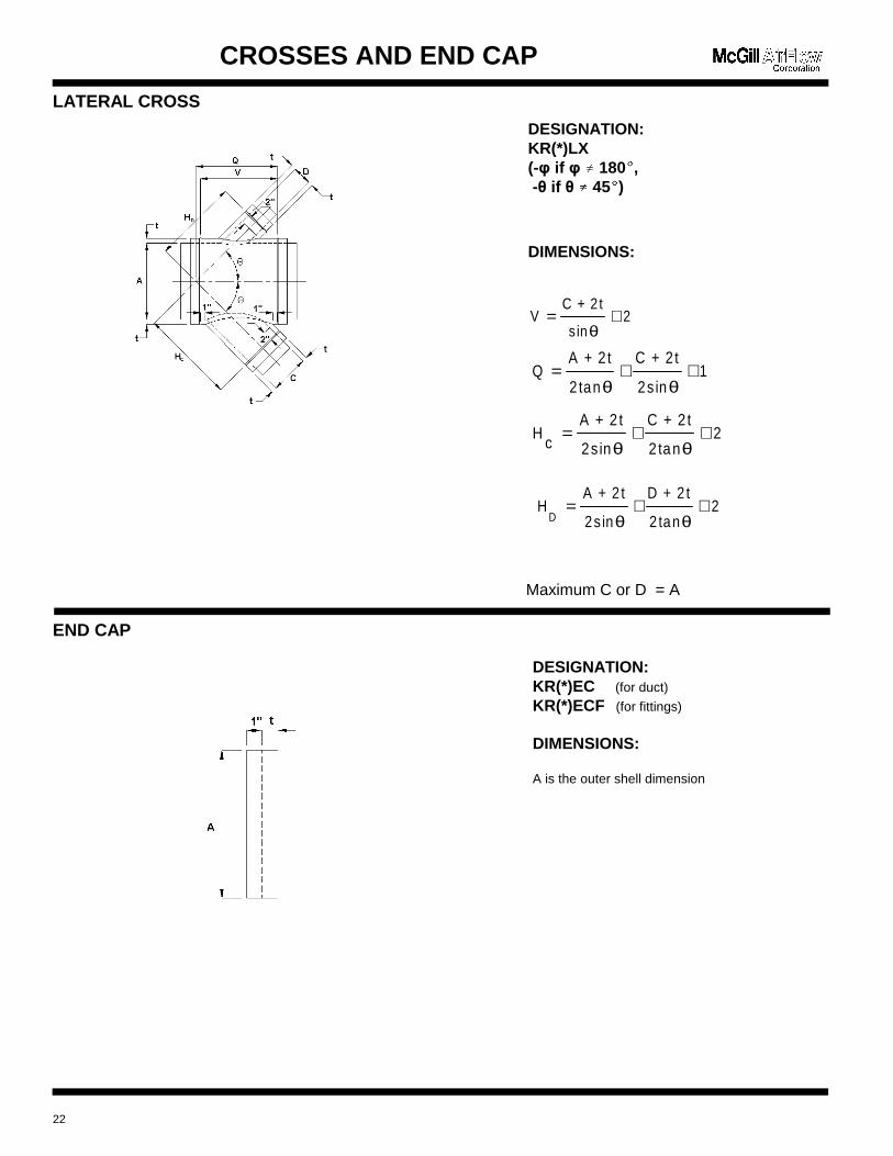
Maximum C or D = A
END CAP
22
DESIGNATION:KR(*)LX(-3 if 3 g� 180(
�,
-� if � g� 45(�)
DIMENSIONS:
DESIGNATION:KR(*)EC (for duct)
KR(*)ECF (for fittings)
DIMENSIONS:
A is the outer shell dimension
VC + 2t
s in2= +
θ
QA + 2t
2 tan
C + 2t
2s in1= + +
θ θ
Hc
A + 2t
2s in
C + 2t
2 tan2= + +
θ θ
HA + 2t
2s in
D + 2 t
2 tan2
D= + +
θ θ
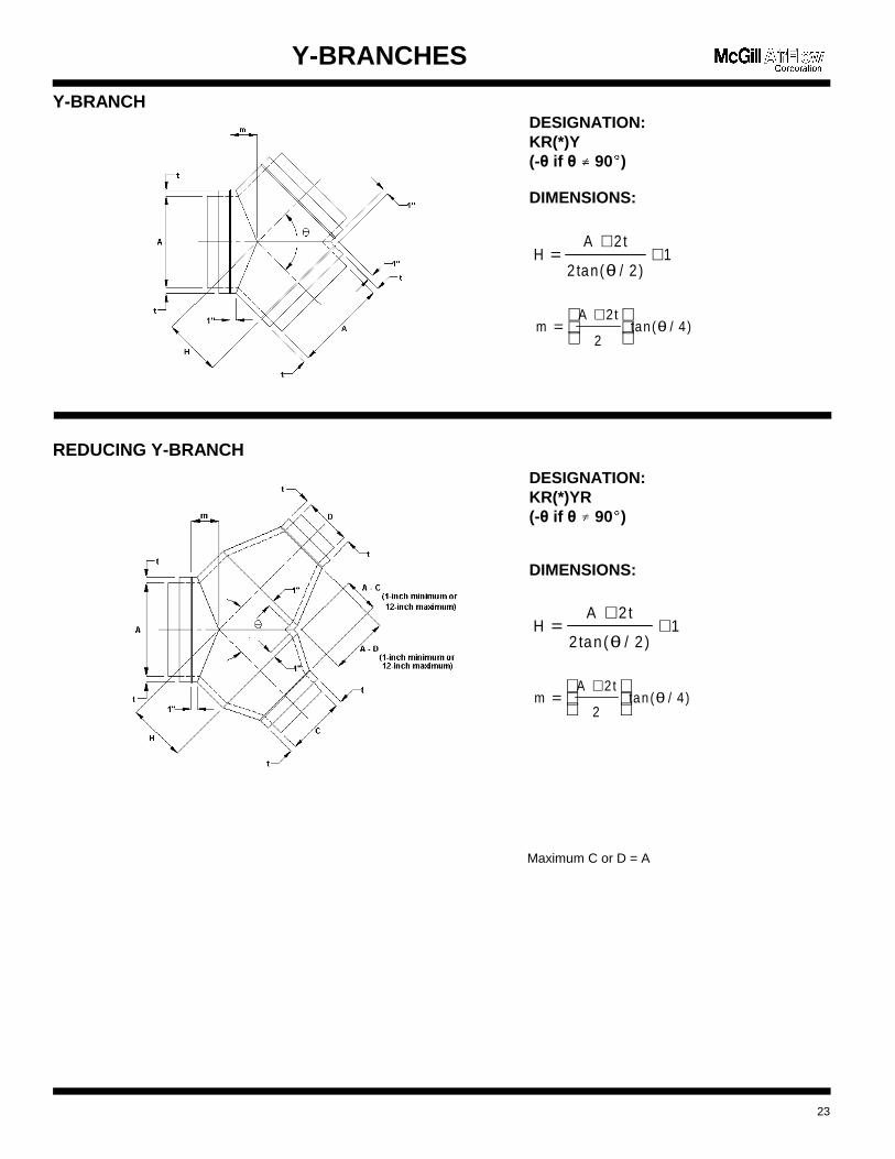
Y-BRANCHES
Y-BRANCH
REDUCING Y-BRANCH
Maximum C or D = A
23
HA 2t
2 tan( / 2 )1=
++
θ
mA 2t
2tan ( / 4)=
+
θ
DESIGNATION:KR(*)Y(-� if � g� 90(
�)
DIMENSIONS:
mA 2t
2tan ( / 4)=
+
θ
HA 2t
2 tan( / 2 )1=
++
θ
DESIGNATION:KR(*)YR(-� if � g� 90(
�)
DIMENSIONS:
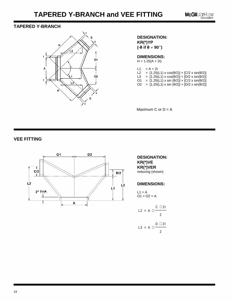
DESIGNATION:KR(*)YP(-� if � g� 90(
�
)
DIMENSIONS:H = 1.25(A + 2t)
L1 = A + 2tL2 = [1.25(L1) x cos(�/2)] + [C/2 x sin(�/2)]L3 = [1.25(L1) x cos(�/2)] + [D/2 x sin(�/2)]O1 = [1.25(L1) x sin (�/2)] + [C/2 x sin(�/2)]O2 = [1.25(L1) x sin (�/2)] + [D/2 x sin(�/2)]
L2 AC 2t
2= +
+
L3 AD 2t
2= +
+
DESIGNATION:KR(*)VEKR(*)VERreducing (shown)
DIMENSIONS:
L1 = AO1 = O2 = A
TAPERED Y-BRANCH and VEE FITTING
TAPERED Y-BRANCH
Maximum C or D = A
VEE FITTING
24
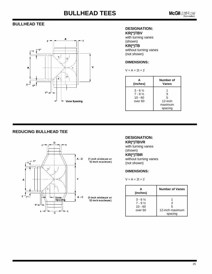
BULLHEAD TEES
BULLHEAD TEE
REDUCING BULLHEAD TEE
25
DESIGNATION:KR(*)TBVwith turning vanes(shown)KR(*)TBwithout turning vanes(not shown)
DIMENSIONS:
V = A + 2t + 2
A(inches)
Number ofVanes
3 - 6 ½7 - 9 ½10 - 60over 60
135
12-inchmaximumspacing
DESIGNATION:KR(*)TBVRwith turning vanes(shown)KR(*)TBRwithout turning vanes(not shown)
DIMENSIONS:
V = A + 2t + 2
A(inches)
Number of Vanes
3 - 6 ½7 - 9 ½10 - 60over 60
135
12-inch maximumspacing
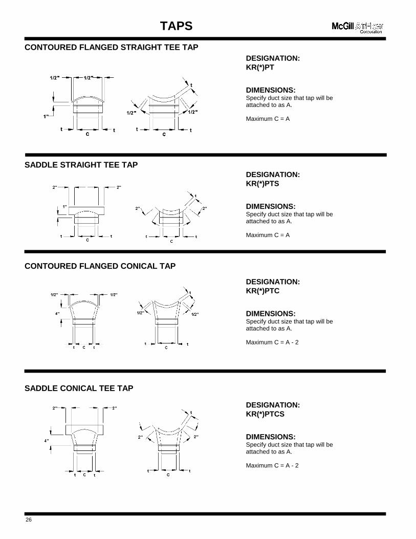
DESIGNATION:KR(*)PT
DIMENSIONS:Specify duct size that tap will beattached to as A.
Maximum C = A
DESIGNATION:KR(*)PTS
DIMENSIONS:Specify duct size that tap will beattached to as A.
Maximum C = A
DESIGNATION:KR(*)PTC
DIMENSIONS:Specify duct size that tap will beattached to as A.
Maximum C = A - 2
DESIGNATION:KR(*)PTCS
DIMENSIONS:Specify duct size that tap will beattached to as A.
Maximum C = A - 2
TAPS
CONTOURED FLANGED STRAIGHT TEE TAP
SADDLE STRAIGHT TEE TAP
CONTOURED FLANGED CONICAL TAP
SADDLE CONICAL TEE TAP
26
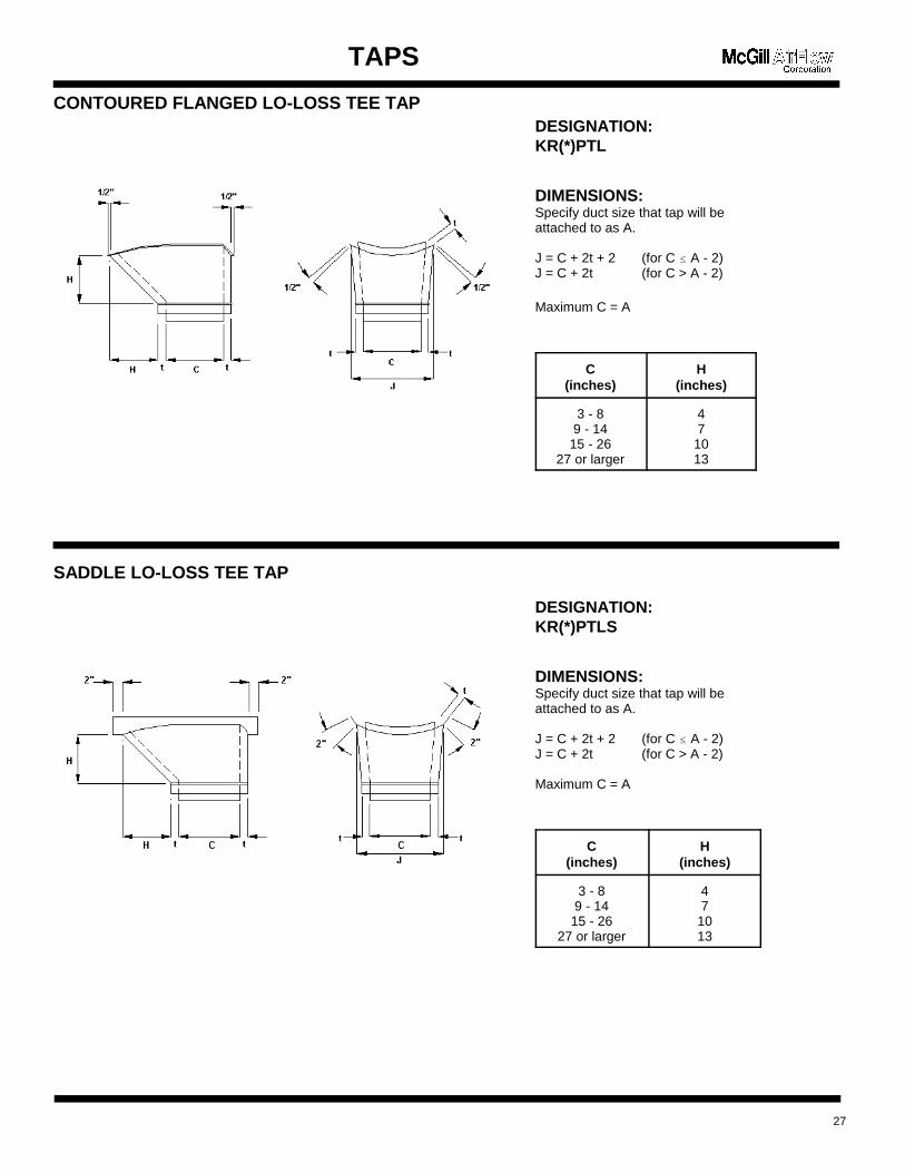
DESIGNATION:KR(*)PTL
DIMENSIONS:Specify duct size that tap will beattached to as A.
J = C + 2t + 2 (for C � A - 2)J = C + 2t (for C > A - 2)
Maximum C = A
C(inches)
H(inches)
3 - 89 - 14
15 - 2627 or larger
47
1013
DESIGNATION:KR(*)PTLS
DIMENSIONS:Specify duct size that tap will beattached to as A.
J = C + 2t + 2 (for C � A - 2)J = C + 2t (for C > A - 2)
Maximum C = A
C(inches)
H(inches)
3 - 89 - 14
15 - 2627 or larger
47
1013
TAPS
CONTOURED FLANGED LO-LOSS TEE TAP
SADDLE LO-LOSS TEE TAP
27
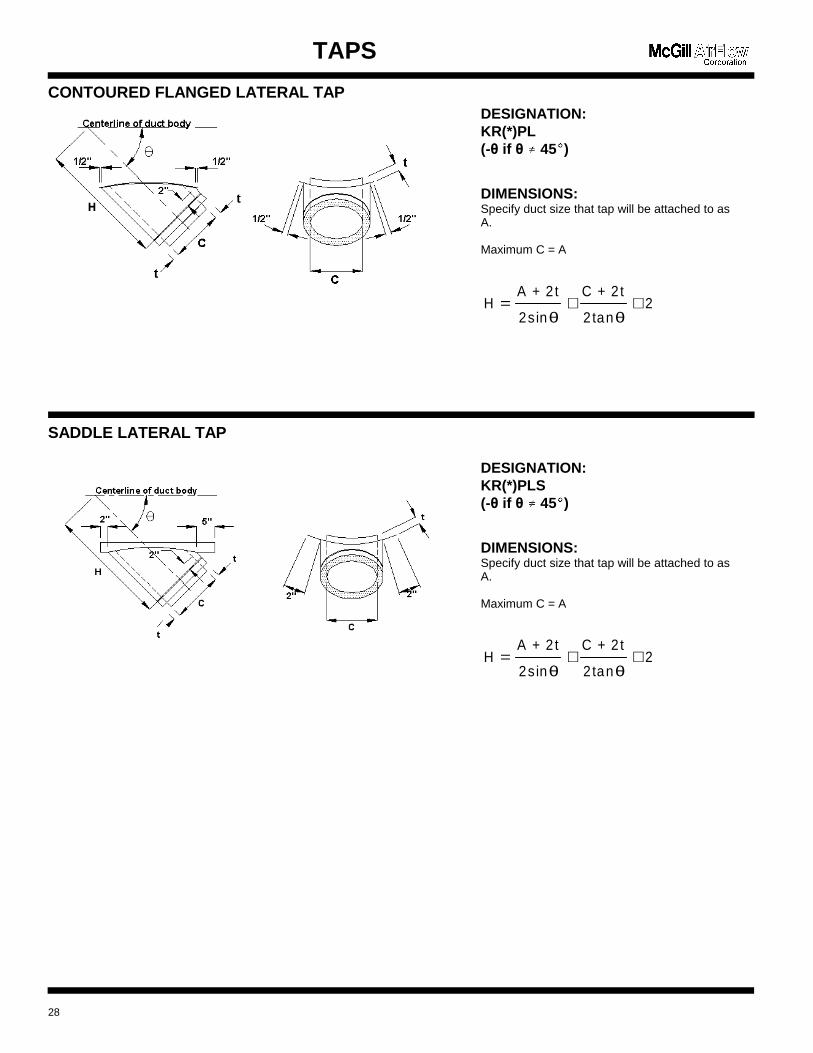
HA + 2t
2sin
C + 2t
2 tan2= + +
θ θ
DESIGNATION:KR(*)PL(-� if � g� 45(
�)
DIMENSIONS:Specify duct size that tap will be attached to asA.
Maximum C = A
HA + 2t
2sin
C + 2t
2 tan2= + +
θ θ
DESIGNATION:KR(*)PLS(-� if � g� 45(
�)
DIMENSIONS:Specify duct size that tap will be attached to asA.
Maximum C = A
TAPS
CONTOURED FLANGED LATERAL TAP
SADDLE LATERAL TAP
28
HA + 2t
2s in
C 2 2 t
2 tan4= +
+ ++
θ
α
θ
α
θ
=+ +
+
2
(C 2 t 2 )
4 tan2
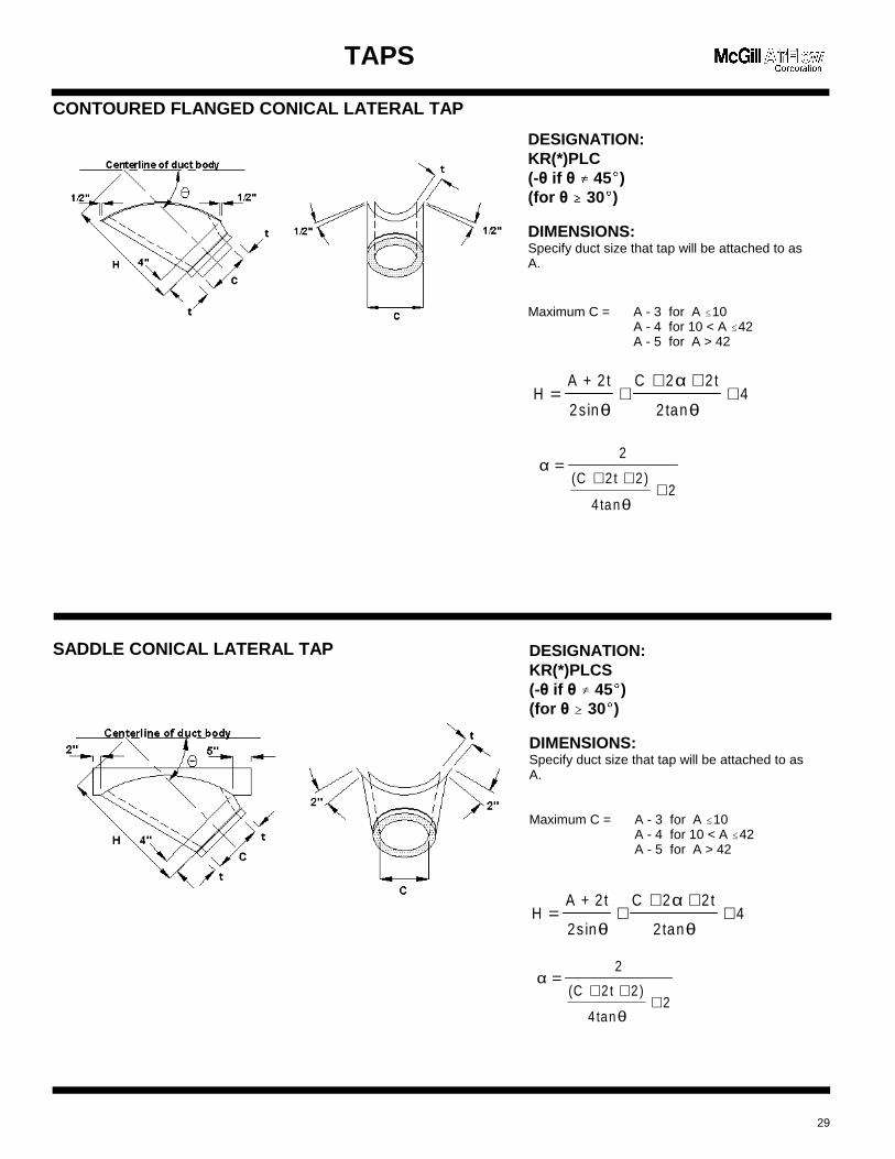
DESIGNATION:KR(*)PLC(-� if � g� 45(
�)
(for � �� 30(�)
DIMENSIONS:Specify duct size that tap will be attached to asA.
Maximum C = A - 3 for A �10A - 4 for 10 < A �42A - 5 for A > 42
HA + 2t
2s in
C 2 2t
2 tan4= +
+ ++
θ
α
θ
α
θ
=+ +
+
2
(C 2 t 2 )
4 tan2
DESIGNATION:KR(*)PLCS(-� if � g� 45(
�)
(for � �� 30(�)
DIMENSIONS:Specify duct size that tap will be attached to asA.
Maximum C = A - 3 for A �10A - 4 for 10 < A �42A - 5 for A > 42
TAPS
CONTOURED FLANGED CONICAL LATERAL TAP
SADDLE CONICAL LATERAL TAP
29
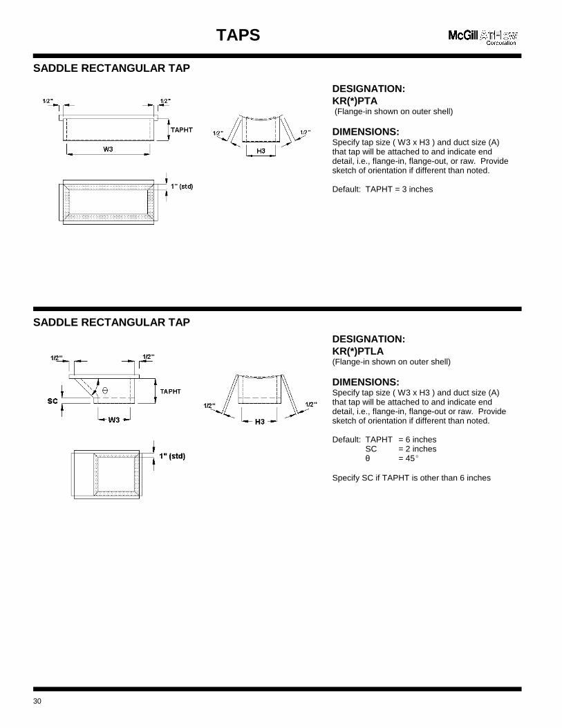
DESIGNATION:KR(*)PTA (Flange-in shown on outer shell)
DIMENSIONS:Specify tap size ( W3 x H3 ) and duct size (A)that tap will be attached to and indicate enddetail, i.e., flange-in, flange-out, or raw. Providesketch of orientation if different than noted.
Default: TAPHT = 3 inches
DESIGNATION:KR(*)PTLA(Flange-in shown on outer shell)
DIMENSIONS:Specify tap size ( W3 x H3 ) and duct size (A)that tap will be attached to and indicate enddetail, i.e., flange-in, flange-out or raw. Providesketch of orientation if different than noted.
Default: TAPHT = 6 inchesSC = 2 inches� = 45(
Specify SC if TAPHT is other than 6 inches
TAPS
SADDLE RECTANGULAR TAP
SADDLE RECTANGULAR TAP
30
OFFSET and SQUARE-TO-ROUND
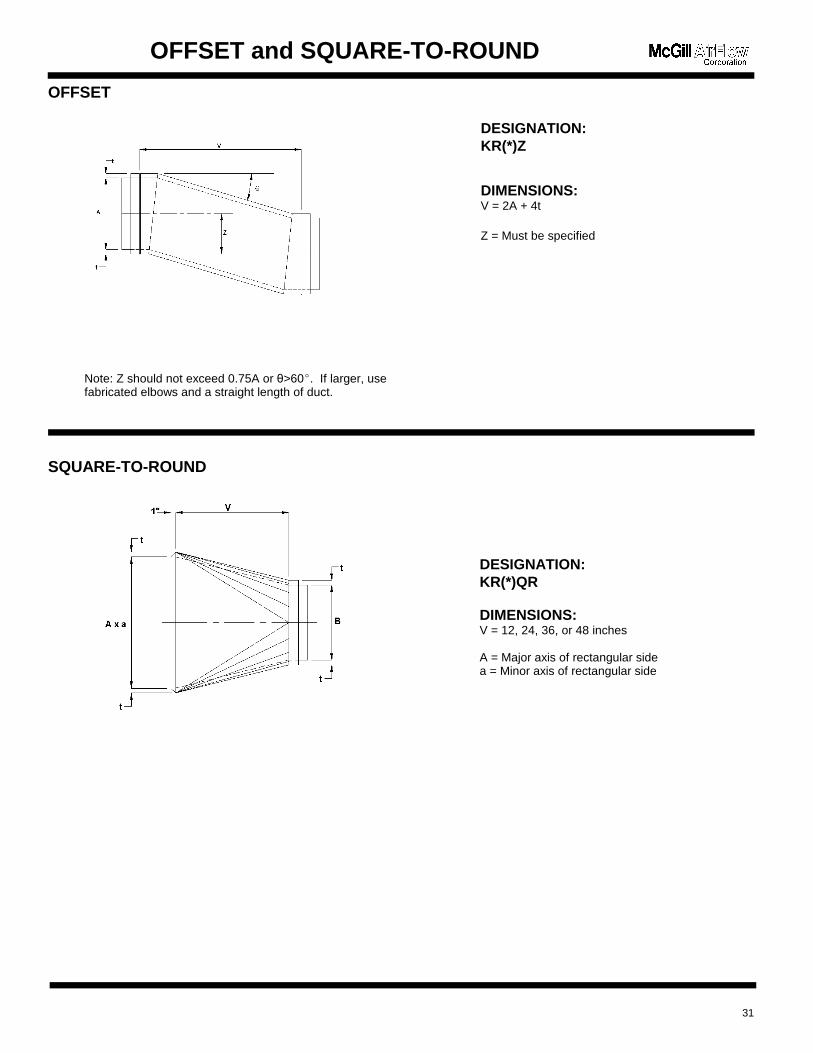
OFFSET
SQUARE-TO-ROUND
31
DESIGNATION:KR(*)Z
DIMENSIONS:V = 2A + 4t
Z = Must be specified
DESIGNATION:KR(*)QR
DIMENSIONS:V = 12, 24, 36, or 48 inches
A = Major axis of rectangular sidea = Minor axis of rectangular side
Note: Z should not exceed 0.75A or �>60(. If larger, usefabricated elbows and a straight length of duct.
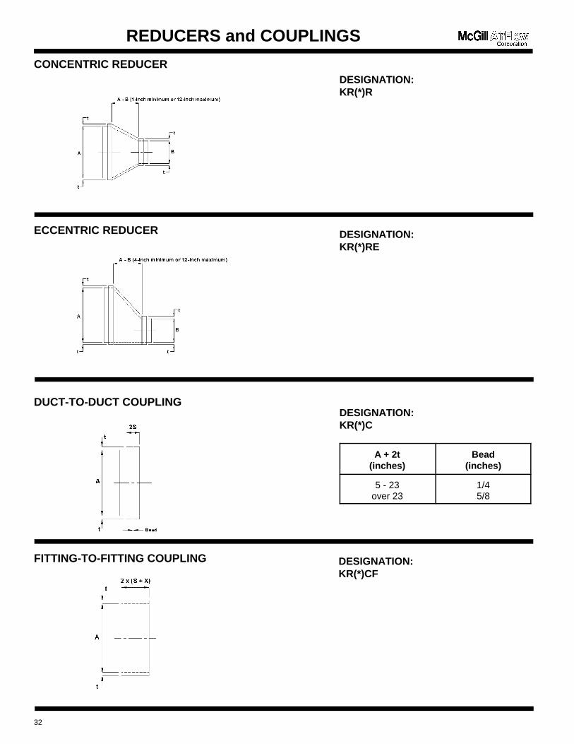
REDUCERS and COUPLINGS
CONCENTRIC REDUCER
ECCENTRIC REDUCER
DUCT-TO-DUCT COUPLING
FITTING-TO-FITTING COUPLING
32
DESIGNATION:KR(*)R
DESIGNATION:KR(*)RE
DESIGNATION:KR(*)C
A + 2t(inches)
Bead(inches)
5 - 23over 23
1/45/8
DESIGNATION:KR(*)CF
INSULATION ENDS
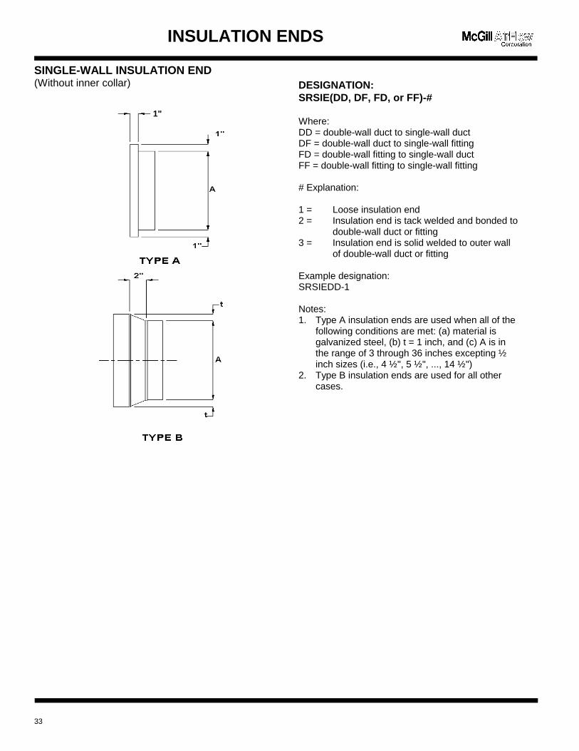
SINGLE-WALL INSULATION END(Without inner collar)
33
DESIGNATION:SRSIE(DD, DF, FD, or FF)-#
Where:DD = double-wall duct to single-wall ductDF = double-wall duct to single-wall fittingFD = double-wall fitting to single-wall ductFF = double-wall fitting to single-wall fitting
# Explanation:
1 = Loose insulation end2 = Insulation end is tack welded and bonded to
double-wall duct or fitting3 = Insulation end is solid welded to outer wall
of double-wall duct or fitting
Example designation:SRSIEDD-1
Notes:1. Type A insulation ends are used when all of the
following conditions are met: (a) material isgalvanized steel, (b) t = 1 inch, and (c) A is inthe range of 3 through 36 inches excepting ½inch sizes (i.e., 4 ½", 5 ½", ..., 14 ½")
2. Type B insulation ends are used for all othercases.
1"
INSULATION ENDS
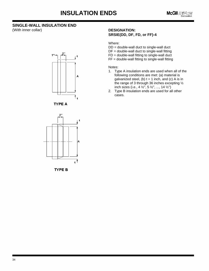
SINGLE-WALL INSULATION END(With inner collar)
34
DESIGNATION:SRSIE(DD, DF, FD, or FF)-4
Where:DD = double-wall duct to single-wall ductDF = double-wall duct to single-wall fittingFD = double-wall fitting to single-wall ductFF = double-wall fitting to single-wall fitting
Notes:1. Type A insulation ends are used when all of the
following conditions are met: (a) material isgalvanized steel, (b) t = 1 inch, and (c) A is inthe range of 3 through 36 inches excepting ½inch sizes (i.e., 4 ½", 5 ½", ..., 14 ½")
2. Type B insulation ends are used for all othercases.
ANGLE RING
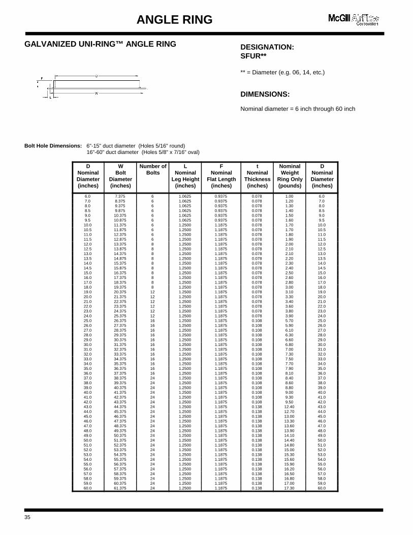
GALVANIZED UNI-RING™ ANGLE RING
Bolt Hole Dimensions: 6"-15" duct diameter (Holes 5/16" round) 16"-60" duct diameter (Holes 5/8" x 7/16" oval)
DNominalDiameter(inches)
WBolt
Diameter(inches)
Number ofBolts
LNominal
Leg Height(inches)
FNominal
Flat Length(inches)
tNominal
Thickness(inches)
NominalWeight
Ring Only(pound s)
DNominalDiameter(inches)
6.0 7.375 6 1.0625 0.9375 0.078 1.00 6.0 7.0 8.375 6 1.0625 0.9375 0.078 1.20 7.0 8.0 9.375 6 1.0625 0.9375 0.078 1.30 8.0 8.5 9.875 6 1.0625 0.9375 0.078 1.40 8.5 9.0 10.375 6 1.0625 0.9375 0.078 1.50 9.0 9.5 10.875 6 1.0625 0.9375 0.078 1.60 9.5 10.0 11.375 6 1.2500 1.1875 0.078 1.70 10.0 10.5 11.875 6 1.2500 1.1875 0.078 1.70 10.5 11.0 12.375 6 1.2500 1.1875 0.078 1.80 11.0 11.5 12.875 6 1.2500 1.1875 0.078 1.90 11.5 12.0 13.375 8 1.2500 1.1875 0.078 2.00 12.0 12.5 13.875 8 1.2500 1.1875 0.078 2.10 12.5 13.0 14.375 8 1.2500 1.1875 0.078 2.10 13.0 13.5 14.875 8 1.2500 1.1875 0.078 2.20 13.5 14.0 15.375 8 1.2500 1.1875 0.078 2.30 14.0 14.5 15.875 8 1.2500 1.1875 0.078 2.40 14.5 15.0 16.375 8 1.2500 1.1875 0.078 2.50 15.0 16.0 17.375 8 1.2500 1.1875 0.078 2.60 16.0 17.0 18.375 8 1.2500 1.1875 0.078 2.80 17.0 18.0 19.375 8 1.2500 1.1875 0.078 3.00 18.0 19.0 20.375 12 1.2500 1.1875 0.078 3.10 19.0 20.0 21.375 12 1.2500 1.1875 0.078 3.30 20.0 21.0 22.375 12 1.2500 1.1875 0.078 3.40 21.0 22.0 23.375 12 1.2500 1.1875 0.078 3.60 22.0 23.0 24.375 12 1.2500 1.1875 0.078 3.80 23.0 24.0 25.375 12 1.2500 1.1875 0.078 3.90 24.0 25.0 26.375 16 1.2500 1.1875 0.108 5.70 25.0 26.0 27.375 16 1.2500 1.1875 0.108 5.90 26.0 27.0 28.375 16 1.2500 1.1875 0.108 6.10 27.0 28.0 29.375 16 1.2500 1.1875 0.108 6.30 28.0 29.0 30.375 16 1.2500 1.1875 0.108 6.60 29.0 30.0 31.375 16 1.2500 1.1875 0.108 6.80 30.0 31.0 32.375 16 1.2500 1.1875 0.108 7.00 31.0 32.0 33.375 16 1.2500 1.1875 0.108 7.30 32.0 33.0 34.375 16 1.2500 1.1875 0.108 7.50 33.0 34.0 35.375 16 1.2500 1.1875 0.108 7.70 34.0 35.0 36.375 16 1.2500 1.1875 0.108 7.90 35.0 36.0 37.375 16 1.2500 1.1875 0.108 8.10 36.0 37.0 38.375 24 1.2500 1.1875 0.108 8.40 37.0 38.0 39.375 24 1.2500 1.1875 0.108 8.60 38.0 39.0 40.375 24 1.2500 1.1875 0.108 8.80 39.0 40.0 41.375 24 1.2500 1.1875 0.108 9.00 40.0 41.0 42.375 24 1.2500 1.1875 0.108 9.30 41.0 42.0 43.375 24 1.2500 1.1875 0.108 9.50 42.0 43.0 44.375 24 1.2500 1.1875 0.138 12.40 43.0 44.0 45.375 24 1.2500 1.1875 0.138 12.70 44.0 45.0 46.375 24 1.2500 1.1875 0.138 13.00 45.0 46.0 47.375 24 1.2500 1.1875 0.138 13.30 46.0 47.0 48.375 24 1.2500 1.1875 0.138 13.60 47.0 48.0 49.375 24 1.2500 1.1875 0.138 13.90 48.0 49.0 50.375 24 1.2500 1.1875 0.138 14.10 49.0 50.0 51.375 24 1.2500 1.1875 0.138 14.40 50.0 51.0 52.375 24 1.2500 1.1875 0.138 14.80 51.0 52.0 53.375 24 1.2500 1.1875 0.138 15.00 52.0 53.0 54.375 24 1.2500 1.1875 0.138 15.30 53.0 54.0 55.375 24 1.2500 1.1875 0.138 15.60 54.0 55.0 56.375 24 1.2500 1.1875 0.138 15.90 55.0 56.0 57.375 24 1.2500 1.1875 0.138 16.20 56.0 57.0 58.375 24 1.2500 1.1875 0.138 16.50 57.0 58.0 59.375 24 1.2500 1.1875 0.138 16.80 58.0 59.0 60.375 24 1.2500 1.1875 0.138 17.00 59.0 60.0 61.375 24 1.2500 1.1875 0.138 17.30 60.0
35
DESIGNATION:SFUR**
** = Diameter (e.g. 06, 14, etc.)
DIMENSIONS:
Nominal diameter = 6 inch through 60 inch
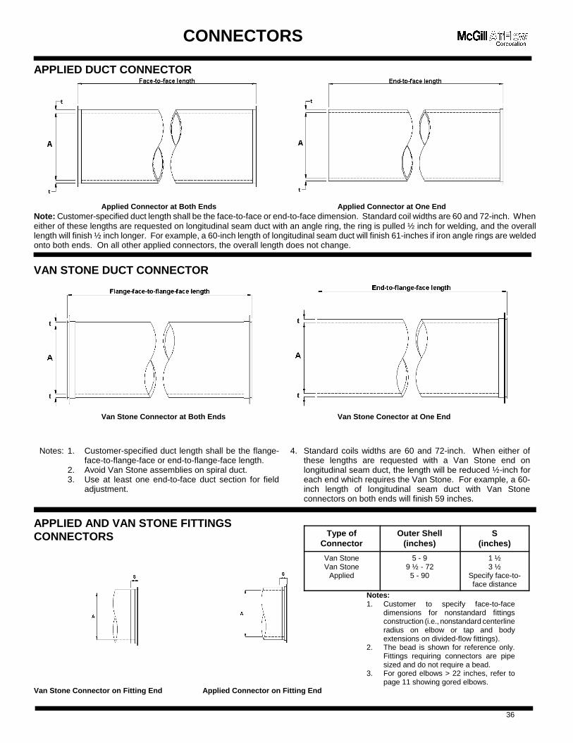
Type ofConnector
Outer Shell(inches)
S(inches)
Van StoneVan Stone
Applied
5 - 99 ½ - 72
5 - 90
1 ½3 ½
Specify face-to-face distance
Notes:1. Customer to specify face-to-face
dimensions for nonstandard fittingsconstruction (i.e., nonstandard centerlineradius on elbow or tap and bodyextensions on divided-flow fittings).
2. The bead is shown for reference only.Fittings requiring connectors are pipesized and do not require a bead.
3. For gored elbows > 22 inches, refer topage 11 showing gored elbows.
CONNECTORS
APPLIED DUCT CONNECTOR
Applied Connector at Both Ends Applied Connector at One EndNote: Customer-specified duct length shall be the face-to-face or end-to-face dimension. Standard coil widths are 60 and 72-inch. Wheneither of these lengths are requested on longitudinal seam duct with an angle ring, the ring is pulled ½ inch for welding, and the overalllength will finish ½ inch longer. For example, a 60-inch length of longitudinal seam duct will finish 61-inches if iron angle rings are weldedonto both ends. On all other applied connectors, the overall length does not change.
VAN STONE DUCT CONNECTOR
Van Stone Connector at Both Ends Van Stone Conector at One End
Notes: 1. Customer-specified duct length shall be the flange-face-to-flange-face or end-to-flange-face length.
2. Avoid Van Stone assemblies on spiral duct.3. Use at least one end-to-face duct section for field
adjustment.
4. Standard coils widths are 60 and 72-inch. When either ofthese lengths are requested with a Van Stone end onlongitudinal seam duct, the length will be reduced ½-inch foreach end which requires the Van Stone. For example, a 60-inch length of longitudinal seam duct with Van Stoneconnectors on both ends will finish 59 inches.
APPLIED AND VAN STONE FITTINGSCONNECTORS
Van Stone Connector on Fitting End Applied Connector on Fitting End
36
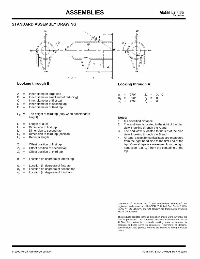
Looking through A:
3C = 270( ZC = X, -X3D = 90( ZD = 03E = 270( ZE = 0
Notes: 1. X = specified distance2. The end view is located to the right of the plan
view if looking through the A end.3. The end view is located to the left of the plan
view if looking through the B end.4. All taps, except for conical taps, are measured
from the right hand side to the first end of thetap. Conical taps are measured from the righthand side (e.g. LE ) from the centerline of thetap.
Looking through B:
A = Inner diameter large endB = Inner diameter small end (if reducing)C = Inner diameter of first tapD = Inner diameter of second tapE = Inner diameter of third tap
HE = Tap height of third tap (only when nonstandardheight)
L = Length of ductLC = Dimension to first tapLD = Dimension to second tapLE = Dimension to third tap (conical)LR = Reducer length
ZC = Offset position of first tapZD = Offset position of second tapZE = Offset position of third tap
� = Location (in degrees) of lateral tap
3C = Location (in degrees) of first tap3D = Location (in degrees) of second tap3E = Location (in degrees) of third tap
ASSEMBLIES
STANDARD ASSEMBLY DRAWING
UNI-RIB-k27®, ACOUSTI-k27®, and Longitudinal Seam-k27® areregistered trademarks, and UNI-SEAL™, United Duct Sealer™, UNI-SEAM™ , LO-LOSS™, and UNI-RING™ are trademarks of UnitedMcGill Corporation.
The products depicted in these dimension sheets were current at thetime of publication. As a quality conscious manufacturer, McGillAirFlow Corporation is constantly seeking ways to improve itsproducts to better serve its customers. Therefore, all designs,specifications, and product features are subject to change withoutnotice.
© 1999 McGill AirFlow Corporation Form No.: SMD-DWRDS Rev. 5 11/99

An enterprise of United McGill Corporation —Founded in 1951
Corporate HeadquartersOne Mission ParkGroveport, Ohio 43125-1149614/836-9981, Fax: 614/836-9843E-mail: [email protected] site: mcgillairflow.com