pro/engineer: design documentation and detailing
TRANSCRIPT
Pro/ENGINEER:Design Documentation and Detailing
Wildfire 5Student Guide
Revision 1.0April 2011
PR
OP
ER
TY
OF
AS
CE
NT
86
6- 5
27
- 23
68

PR
OP
ER
TY
OF
AS
CE
NT
86
6- 5
27
- 23
68

P
ASCENT - Center for Technical Knowledge®
Pro/ENGINEER: Design Documentation and DetailingWildfire 5, Revision 1.0
ASCENT - Center for Technical Knowledge is a division of RAND Worldwide Inc., providing custom developed knowledge products and services for leading engineering software applications. ASCENT is focused on specializing in the creation of education programs that incorporate the best of classroom learning and technology-based training offerings.
We welcome any comments you may have regarding this training manual, or any of our products. To contact us please email: [email protected].
© ASCENT - Center for Technical Knowledge, 2011Printed in the United States of America, all rights reserved. No part of this manual may be reproduced in any form by any photographic, electronic, mechanical or other means or used in any information storage and retrieval system without the written permission of ASCENT, a division of RAND Worldwide, Inc.
Pro/ENGINEER is a registered trademark of Parametric Technology Corporation.
General Disclaimer:NOTWITHSTANDING ANY LANGUAGE TO THE CONTRARY, NOTHING CONTAINED HEREIN CONSTITUTES NOR IS INTENDED TO CONSTITUTE AN OFFER, INDUCEMENT, PROMISE, OR CONTRACT OF ANY KIND. THE DATA CONTAINED HEREIN IS FOR INFORMATIONAL PURPOSES ONLY AND IS NOT REPRESENTED TO BE ERROR FREE. ASCENT, ITS AGENTS AND EMPLOYEES, EXPRESSLY DISCLAIM ANY LIABILITY FOR ANY DAMAGES, LOSSES OR OTHER EXPENSES ARISING IN CONNECTION WITH THE USE OF ITS MATERIALS OR IN CONNECTION WITH ANY FAILURE OF PERFORMANCE, ERROR, OMISSION EVEN IF ASCENT, OR ITS REPRESENTATIVES, ARE ADVISED OF THE POSSIBILITY OF SUCH DAMAGES, LOSSES OR OTHER EXPENSES. NO CONSEQUENTIAL DAMAGES CAN BE SOUGHT AGAINST ASCENT OR RAND WORLDWIDE FOR THE USE OF THESE MATERIALS BY ANY THIRD PARTIES OR FOR ANY DIRECT OR INDIRECT RESULT OF THAT USE.
THE INFORMATION CONTAINED HEREIN IS INTENDED TO BE OF GENERAL INTEREST TO YOU AND IS PROVIDED "AS IS", AND IT DOES NOT ADDRESS THE CIRCUMSTANCES OF ANY PARTICULAR INDIVIDUAL OR ENTITY. NOTHING HEREIN CONSTITUTES PROFESSIONAL ADVICE, NOR DOES IT CONSTITUTE A COMPREHENSIVE OR COMPLETE STATEMENT OF THE ISSUES DISCUSSED THERETO. ASCENT DOES NOT WARRANT THAT THE DOCUMENT OR INFORMATION WILL BE ERROR FREE OR WILL MEET ANY PARTICULAR CRITERIA OF PERFORMANCE OR QUALITY. IN PARTICULAR (BUT WITHOUT LIMITATION) INFORMATION MAY BE RENDERED INACCURATE BY CHANGES MADE TO THE SUBJECT OF THE MATERIALS (I.E. APPLICABLE SOFTWARE). RAND SPECIFICALLY DISCLAIMS ANY WARRANTY, EITHER EXPRESSED OR IMPLIED, INCLUDING THE WARRANTY OF FITNESS FOR A PARTIC-ULAR PURPOSE.
Prepared and produced by:
ASCENT Center for Technical Knowledge1001 E. Market Street, Suite 102 Charlottesville, VA 22902
866-527-2368 www.ascented.com
RO
PE
RT
Y O
F A
SC
EN
T
86
6- 5
27
- 23
68

PR
OP
ER
TY
OF
AS
CE
NT
86
6- 5
27
- 23
68

Table of Contents
Table of Contents
Chapter 1 Views............................................................................ 1-11.1 General Steps for Drawings............................................ 1-31.2 Create a New Drawing ..................................................... 1-4
Use Template.................................................................. 1-5Empty with Format .......................................................... 1-6Empty .............................................................................. 1-7
1.3 Drawing Mode Interface .................................................. 1-8Pan, Zoom..................................................................... 1-10Selection Tool ............................................................... 1-11Pop-up Menus............................................................... 1-11Undo/Redo .................................................................... 1-13Drawing Tree................................................................. 1-14
1.4 Place the First Drawing View........................................ 1-151.5 Place Additional Views.................................................. 1-191.6 Modify View Properties ................................................. 1-25
Visible Area ................................................................... 1-26Scale ............................................................................. 1-28Sections ........................................................................ 1-29
1.7 Drawing Environment Options ..................................... 1-39Environment Dialog Box................................................ 1-39Drawing Setup File........................................................ 1-40Config.pro File............................................................... 1-41
Exercise 1a Create a New Drawing .................................... 1-43Exercise 1b Add a Drawing Format.................................... 1-52Exercise 1c Create Views.................................................... 1-63Exercise 1d Create Views with Break Lines ...................... 1-72Exercise 1e Create a Drawing............................................. 1-78
Chapter 2 View Manipulation ...................................................... 2-12.1 Modify View Properties II ................................................ 2-3
View Type ....................................................................... 2-4View Manager States ...................................................... 2-8View Display.................................................................... 2-9Origin............................................................................. 2-11Alignment ...................................................................... 2-13
2.2 Manipulate Drawing Views............................................ 2-14View Alignment ............................................................. 2-14Moving Views ................................................................ 2-14
PR
OP
ER
TY
OF
AS
CE
NT
86
6- 5
27
- 23
68
© 2011, ASCENT - Center for Technical Knowledge® i
Pro/ENGINEER: Advanced Assembly Design and Management
Delete Views................................................................. 2-15Erasing Views ............................................................... 2-16Drawing Display ............................................................ 2-16
2.3 Configuration Options .................................................. 2-19Exercise 2a Move Drawing Views ...................................... 2-21Exercise 2b Move Broken Views........................................ 2-30Exercise 2c Modify Drawing Views.................................... 2-33Exercise 2d Modify View Boundaries ................................ 2-38
Chapter 3 Detailing a Drawing .................................................... 3-13.1 Show Detail Items............................................................ 3-33.2 Create Dimensions .......................................................... 3-9
Coordinate Dimensions................................................. 3-14
3.3 Manipulate Detail Items................................................. 3-16Modify Dimensions........................................................ 3-17Delete............................................................................ 3-19Move ............................................................................. 3-19Edit Attachment............................................................. 3-20Breaking Cross-Hatch Lines ......................................... 3-24Break............................................................................. 3-24Clip................................................................................ 3-26Move Item to View ........................................................ 3-26Flip Arrows .................................................................... 3-26Make Jog ...................................................................... 3-27Align Dimensions .......................................................... 3-27Snap Lines .................................................................... 3-28Cleaning Dimensions .................................................... 3-28Erase Witness Lines ..................................................... 3-29Diameter/Linear Format ................................................ 3-30Radial and Diameter Dimensions ................................. 3-30Automatic Clipped Dimensions ..................................... 3-31
3.4 Customizing Options .................................................... 3-33Exercise 3a Showing Detail Items...................................... 3-35Exercise 3b Showing Detail Items II................................... 3-46Exercise 3c Creating Dimensions...................................... 3-58Exercise 3d Ordinate Dimensions...................................... 3-64
Chapter 4 Project Labs................................................................ 4-1Project Lab 2 Creating a Detailed Drawing ......................... 4-3Project Lab 2 Creating 3D Drawings.................................. 4-12
PR
OP
ER
TY
OF
AS
CE
NT
86
6- 5
27
- 23
68
ii © 2011, ASCENT - Center for Technical Knowledge®

Table of Contents
Chapter 5 Drawing Notes............................................................. 5-15.1 Create & Modify Notes..................................................... 5-3
Dimensions ..................................................................... 5-7System-defined Parameters............................................ 5-8User-defined Parameters ................................................ 5-8Special Characters.......................................................... 5-9User-defined Symbols..................................................... 5-9Moving Notes ................................................................ 5-10Editing Attachments ...................................................... 5-11Modifying Text............................................................... 5-13Hyperlinks ..................................................................... 5-13Superscript and Subscript Text ..................................... 5-14Outlining a Note ............................................................ 5-14Modifying Text Styles .................................................... 5-15Creating a Style Library................................................. 5-16Saving Notes................................................................. 5-17
5.2 Customizing Options..................................................... 5-19Exercise 5a Creating Notes................................................. 5-21Exercise 5b Read a Note From File .................................... 5-27
Chapter 6 Tolerances................................................................... 6-16.1 Showing Dimensional Tolerances.................................. 6-36.2 Set Tolerance Standards................................................. 6-4
ISO Standards................................................................. 6-6ANSI Standards .............................................................. 6-8
6.3 Create Geometric Tolerances......................................... 6-9Set Datums ................................................................... 6-10Copying Geometric Tolerances..................................... 6-17
6.4 Drawing Configuration Options.................................... 6-196.5 Drawing Setup File Options.......................................... 6-21Exercise 6a Dimensional Tolerances................................. 6-22Exercise 6b Geometric Tolerances .................................... 6-26
Chapter 7 Project Lab 3 ............................................................... 7-1Project Lab 3 Tolerancing a Drawing................................... 7-3
PR
OP
ER
TY
OF
AS
CE
NT
86
6- 5
27
- 23
68
© 2011, ASCENT - Center for Technical Knowledge® iii

Pro/ENGINEER: Advanced Assembly Design and Management
Chapter 8 Assembly Drawings ................................................... 8-18.1 Add Models ...................................................................... 8-38.2 Explode Assembly Views ............................................... 8-68.3 Change Component Display........................................... 8-88.4 Display Cross-Sections ................................................ 8-12
Cross-Section Material Files ......................................... 8-143D Cross-Sections ........................................................ 8-14
8.5 Modify Assembly Views................................................ 8-19View State..................................................................... 8-19Combined States .......................................................... 8-20Z-Clipping...................................................................... 8-21
Exercise 8a Assembly Drawing.......................................... 8-22Exercise 8b 3D Cross-section, Simplified Representation, and Combined States........................................................... 8-35
Chapter 9 Drawing Tables ........................................................... 9-19.1 Create a Table .................................................................. 9-3
Selection Methods .......................................................... 9-7Copy Table...................................................................... 9-7Rotate ............................................................................. 9-7Justification ..................................................................... 9-8Size................................................................................. 9-8Insert ............................................................................... 9-9Remove........................................................................... 9-9Merge.............................................................................. 9-9Table Origin .................................................................. 9-10Blank Line Display ........................................................ 9-10
9.2 Create Repeat Regions ................................................. 9-11Filters ............................................................................ 9-16Attributes....................................................................... 9-18Pagination ..................................................................... 9-20Creating BOM Balloons ................................................ 9-20Modifying BOM Balloons............................................... 9-22
9.3 Create Hole, Point, and Axes Tables ........................... 9-23Exercise 9a Bill of Materials (BOM).................................... 9-27Exercise 9b Family Table .................................................... 9-44Exercise 9c Hole, Axis, and Datum Point Tables.............. 9-48
Chapter 10 Two-Dimensional Sketching.................................. 10-110.1 Create 2D Entities.......................................................... 10-3
Line ............................................................................... 10-6Circle............................................................................. 10-6
PR
OP
ER
TY
OF
AS
CE
NT
86
6- 5
27
- 23
68
iv © 2011, ASCENT - Center for Technical Knowledge®

Table of Contents
Ellipse............................................................................ 10-7Arc................................................................................. 10-8Construction Line .......................................................... 10-9Construction Circle...................................................... 10-10Fillet............................................................................. 10-11Chamfer ...................................................................... 10-11Spline .......................................................................... 10-12Point ............................................................................ 10-12Break........................................................................... 10-13Offset and Use Edge................................................... 10-13
10.2 Modify 2D Entities........................................................ 10-15Copy & Paste .............................................................. 10-15Arrange Group ............................................................ 10-15Trim Group .................................................................. 10-16Format Group.............................................................. 10-17Hatch/Fill ..................................................................... 10-18Line Style .................................................................... 10-19
10.3 Group 2D Entities......................................................... 10-20Create a Draft Group................................................... 10-21Relate Draft Items to a View ....................................... 10-21Group Objects with Dimension Text............................ 10-22Ungroup a Draft Group................................................ 10-22Ungroup Items from a View......................................... 10-22Set Drawing View as Current Draft View .................... 10-22Modify a Draft Group................................................... 10-22Suppress a Draft Group .............................................. 10-23Resume a Suppressed Group..................................... 10-23
10.4 Convert to Draft Entities.............................................. 10-2410.5 Sketch Parametric Entities.......................................... 10-25
Chapter 11 Symbols................................................................... 11-111.1 Create Symbol Geometry .............................................. 11-311.2 Place a Custom Symbol .............................................. 11-1211.3 Symbol Palette ............................................................. 11-1611.4 Surface Finish Symbols .............................................. 11-17Exercise 11a Surface Symbols ......................................... 11-18Exercise 11b Custom Symbol Definition Palette ............ 11-32
Chapter 12 Annotation Features............................................... 12-112.1 Create Annotation Features.......................................... 12-312.2 Manipulate Annotation Features ................................ 12-12
Selecting ..................................................................... 12-12Model Tree Display ..................................................... 12-12
PR
OP
ER
TY
OF
AS
CE
NT
86
6- 5
27
- 23
68
© 2011, ASCENT - Center for Technical Knowledge® v

Pro/ENGINEER: Advanced Assembly Design and Management
Editing ......................................................................... 12-13Text Style .................................................................... 12-13Deleting....................................................................... 12-14Disassociating Elements............................................. 12-14Reordering .................................................................. 12-14Controlling Display ...................................................... 12-15
Exercise 12a Creating Annotation Features ................... 12-16
Chapter 13 Drawing Formats & Templates.............................. 13-113.1 Create a Drawing Format .............................................. 13-3
Empty with section ........................................................ 13-5Empty............................................................................ 13-6
13.2 Import Formats .............................................................. 13-813.3 Add Tables to a Format................................................. 13-913.4 Parametric Text............................................................ 13-1013.5 Add a Drawing Format ................................................ 13-1113.6 Create Drawing Templates ......................................... 13-12Exercise 13a Drawing Formats......................................... 13-15Exercise 13b Formats with Imported Data ...................... 13-18Exercise 13c Drawing Templates ..................................... 13-20
Chapter 14 Feature Management.............................................. 14-114.1 Hide Items ...................................................................... 14-314.2 Suppress Items.............................................................. 14-514.3 Add Layers ..................................................................... 14-8
General Steps............................................................... 14-8Hide............................................................................. 14-11Unhide......................................................................... 14-11Isolate ......................................................................... 14-11Default Layers............................................................. 14-14Display Status of Model Layers vs. Drawing Layers... 14-14Layers with the Same Name....................................... 14-15Controlling Individual View Display ............................. 14-15Active Layer ................................................................ 14-16
14.4 Create Assembly Simplified Representations .......... 14-19Restrictions ................................................................. 14-23
14.5 Part Simplified Representations ................................ 14-24Creating Part Simplified Representations ................... 14-24Creating a Drawing including Part Simplified Representations.......................................................... 14-25
PR
OP
ER
TY
OF
AS
CE
NT
86
6- 5
27
- 23
68
vi © 2011, ASCENT - Center for Technical Knowledge®

Table of Contents
14.6 Review Tools ................................................................ 14-28Update......................................................................... 14-28Compare ..................................................................... 14-30Information Tools ........................................................ 14-32
Exercise 14a Drawing Layers ........................................... 14-35Exercise 14b Drawing of an Assembly Simplified Representation.................................................................... 14-42
Appendix A Object Linking and Embedding ............................ A-1A.1 Object Linking and Embedding ..................................... A-3Exercise A1 Object Linking & Embedding ......................... A-5
Appendix B Accessing Pro/HELP.............................................. B-1B.1 Opening the PTC Help Center........................................ B-3B.2 Drawing Setup File Options........................................... B-4B.3 Drawing Configuration File Options ............................. B-7B.4 System-Defined Drawing Parameters ......................... B-10
Appendix C Publish .................................................................... C-1C.1 Publish Tab...................................................................... C-3
Print/Plot......................................................................... C-4Export to DXF................................................................. C-4
PR
OP
ER
TY
OF
AS
CE
NT
86
6- 5
27
- 23
68
© 2011, ASCENT - Center for Technical Knowledge® vii

Pro/ENGINEER: Advanced Assembly Design and Management
PR
OP
ER
TY
OF
AS
CE
NT
86
6- 5
27
- 23
68
viii © 2011, ASCENT - Center for Technical Knowledge®

EN
T
Chapter 1
Views
Drawings are created to communicate information on how the model is to be built. Accurate representation of the model is key for manufacturing. In this chapter, you learn how to add the basic model views to a new drawing.
This chapter introduces:
General Steps for DrawingsCreate a New DrawingDrawing Mode InterfacePlace the First Drawing ViewPlace Additional ViewsModify View PropertiesDrawing Environment Options
PR
OP
ER
TY
OF
AS
C
86
6- 5
27
- 23
68
1–1

1–2
PR
OP
ER
TY
OF
AS
CE
NT
86
6- 5
27
- 23
68

Views
1.1 General Steps for Drawings
In this course, you learn how to create a production drawing of a part or assembly model by progressing through the following steps:
1. Create a drawing.
2. Place the first drawing view.
3. Place additional views.
4. Modify view properties.
5. Manipulate drawing views, as necessary.
6. Detail the drawing (e.g., dimensions, notes, tolerances etc.).
7. Manipulate detail items, as necessary.
8. Print (or Plot) the drawing.
PR
OP
ER
TY
OF
AS
CE
NT
86
6- 5
27
- 23
68
© 2011, ASCENT - Center for Technical Knowledge® 1–3
Pro/ENGINEER: Design Documentation and Detailing
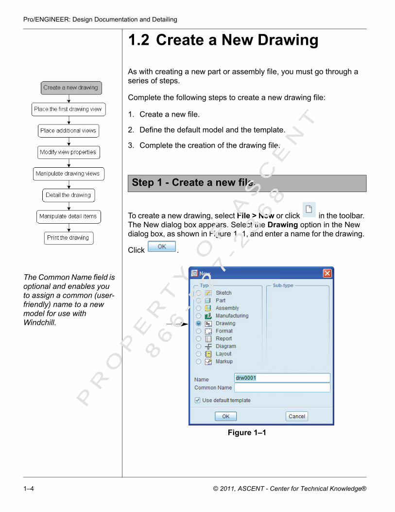
1.2 Create a New Drawing
As with creating a new part or assembly file, you must go through a series of steps.
Complete the following steps to create a new drawing file:
1. Create a new file.
2. Define the default model and the template.
3. Complete the creation of the drawing file.
To create a new drawing, select File > New or click in the toolbar. The New dialog box appears. Select the Drawing option in the New dialog box, as shown in Figure 1–1, and enter a name for the drawing.
Click .
The Common Name field is optional and enables you to assign a common (user- friendly) name to a new model for use with Windchill.
Figure 1–1
Step 1 - Create a new file.
PR
OP
ER
TY
OF
AS
CE
NT
86
6- 5
27
- 23
68
1–4 © 2011, ASCENT - Center for Technical Knowledge®

Views
The next dialog box that appears is the New Drawing dialog box, as shown in Figure 1–2. The Default Model field defines the drawing model to be represented in the drawing. To assign the model, enter
the model name or click . By default, only one model can be selected; additional models can be added once the drawing has been created.
You define the template to be used in the drawing once the default model has been defined. The template options include the following:
• Use Template• Empty with Format• Empty
Use Template To use a predefined drawing template, select the Use template option and select the template name in the Template section, as shown in
Figure 1–2. Alternatively, you can click and browse to other templates that are stored in other directories.
If the Use default template option is selected in the New dialog box, the New Drawing dialog box defaults to the Use Template option, as shown in Figure 1–2. A predefined template is selected for use.
Figure 1–2
Step 2 - Define the default model and the template.
PR
OP
ER
TY
OF
AS
CE
NT
86
6- 5
27
- 23
68
© 2011, ASCENT - Center for Technical Knowledge® 1–5

Pro/ENGINEER: Design Documentation and Detailing
Empty withFormat
To use a predefined drawing format, select the Empty with Format
option. Enter the name of the format or click to browse to a predefined format. The dialog box appears as shown in Figure 1–3.
A template can consist of placed views, pre-defined view displays, placed notes, defined tables, and shown dimensions. A format generally contains standard information, such as borders, title blocks, tables, and company information.
Figure 1–3
PR
OP
ER
TY
OF
AS
CE
NT
86
6- 5
27
- 23
68
1–6 © 2011, ASCENT - Center for Technical Knowledge®

Views
Empty To create a drawing without a template or format, select the Empty option and define the drawing size and orientation, as shown in Figure 1–4.
Figure 1–4
To create the new drawing, click in the New Drawing dialog box.
Step 3 - Complete the creation of the drawing file.
PR
OP
ER
TY
OF
AS
CE
NT
86
6- 5
27
- 23
68
© 2011, ASCENT - Center for Technical Knowledge® 1–7

Pro/ENGINEER: Design Documentation and Detailing
1.3 Drawing Mode Interface
Once the definition of the drawing and its templates have been completed, the Drawing mode user-interface appears. A variety of areas can be manipulated while working in the Drawing mode. Figure 1–5 illustrates the layout of the drawing environment.
Figure 1–5
Pull-down Menus
Message Window (messages and prompts appear in this area)
Drawing Toolbar
Drawing Functional Tabs
Drawing Size
Model NameDrawing Scale
Model Type
Drawing Tree
Model Tree
Drawing Sheet TabsPR
OP
ER
TY
OF
AS
CE
NT
86
6- 5
27
- 23
68
1–8 © 2011, ASCENT - Center for Technical Knowledge®

Views
Drawing mode uses a ribbon style interface with tabs, as shown in Figure 1–6.
Figure 1–6
Tasks are grouped under tabs, and common icons related to the task are grouped under the tab. For example, all view icons are located in the Model View group under the Layout tab. Only commands that are appropriate for the current task are displayed at any given time. The items available in the selection filter automatically change to suit the current task. The functionality found under each tab is shown in Figure 1–7.
Figure 1–7
PR
OP
ER
TY
OF
AS
CE
NT
86
6- 5
27
- 23
68
© 2011, ASCENT - Center for Technical Knowledge® 1–9

Pro/ENGINEER: Design Documentation and Detailing
Commonly used icons are shown in Table 1–1 and discussed throughout this training guide.
Table 1–1
Pan, Zoom If you have a scroll wheel, use the following methods to pan and zoom a drawing:
• Press down on the scroll wheel and drag the mouse to pan.• Roll the scroll wheel to zoom.
If you do not have a scroll wheel, use the following methods to pan and zoom:
• Press the middle mouse button and drag the mouse to pan.• Hold down <Ctrl> and press the middle mouse button to zoom.
Icon Description Icon Description
Delete selected items Create notes
Set the active model Edit hyperlinks
Update the current sheet Repeat last formatting
Regenerate Model Create geometric tolerance
Move object to an exact location Insert drawing symbol
Create snaplines Insert custom drawing symbol
Open the Show/Erase dialog box Insert general view
Create dimensions Insert a table
Lineup dimensions Update a table
Cleanup dimensions Text style
PR
OP
ER
TY
OF
AS
CE
NT
86
6- 5
27
- 23
68
1–10 © 2011, ASCENT - Center for Technical Knowledge®

Views
Selection Tool in the toolbar provides you with various options for selecting items in a drawing. By default, this option enables you to draw a rectangular box. All items specified by the filter that lie entirely within the rectangular box are selected. To select items that lie across the
sketched boundary, click in the pull-down menu. enables you to sketch a polygon that defines the selection area. The remaining selection options in this pull-down are available for facet surfaces.
Pop-up Menus There are many shortcut options available in pop-up menus. To access these shortcuts, select an item and right-click. The options provided in the pop-up menu depend on what item is pre-selected. Table 1–2 shows several possible pop-up menus that appear when different drawing objects are selected.
Table 1–2
Pop-up Menus Pop-up Menus
This pop-up menu is accessed when a drawing view is pre-selected.
This pop-up menu is accessed when a drawing dimension is pre-selected.
PR
OP
ER
TY
OF
AS
CE
NT
86
6- 5
27
- 23
68
© 2011, ASCENT - Center for Technical Knowledge® 1–11

Pro/ENGINEER: Design Documentation and Detailing
Pop-up Menus Pop-up Menus
This pop-up menu is accessed when a drawing table cell is pre-selected.
This pop-up menu is accessed when a view cross-section is pre-selected.
This pop-up menu is accessed when a drawing note is pre-selected.
This pop-up menu is accessed when an entire drawing table is pre-selected.
PR
OP
ER
TY
OF
AS
CE
NT
86
6- 5
27
- 23
68
1–12 © 2011, ASCENT - Center for Technical Knowledge®

Views
Undo/Redo The Undo/Redo functionality exists for drawings. The following types of operations enable undoing and redoing:
The stack represents the list of operations that have been performed on the model.
• Supported operations• Unsupported operations that clear the stack• Unsupported operations that do not clear the stack
The Undo/Redo functionality supports a limited number of operations. For a detailed list of the detailing operations and how they affect Undo/Redo functionality, go to the Help Center and search in the Detailing functional group for “Undo”. Three different articles that discuss each classification; Supported Undo/Redo Operations, Unsupported Undo/Redo Operations (Non-Clearing), and Unsupported Undo/Redo Operations (Stack Clearing).
Pop-up Menus Pop-up Menus
This pop-up menu is accessed when nothing is pre-selected in the Layout tab.
This pop-up menu is accessed when nothing is pre-selected in the Table tab.
This pop-up menu is accessed when nothing is pre-selected in the Annotate tab.
This pop-up menu is accessed when nothing is pre-selected in the Sketch tab.
PR
OP
ER
TY
OF
AS
CE
NT
86
6- 5
27
- 23
68
© 2011, ASCENT - Center for Technical Knowledge® 1–13

Pro/ENGINEER: Design Documentation and Detailing
By default, the stack limit is 50 operations. Once 50 operations have been stored, the first is removed so that only 50 operations are stored in memory. The stack limit is controlled using the general_undo_stack_limit config.pro option.
Drawing Tree The Model Tree is divided into two parts, the Drawing Tree area and the Model Tree area, as shown in Figure 1–8.
Figure 1–8
The content in the drawing tree changes depending on the tab that is currently active. Selected objects highlight in both the drawing tree and graphics window. Shortcut menus are available by right-clicking. The drawing tree displays the following drawing items:
• Sheets• Views• Tables• Created/shown annotations• Datums• Draft entities• Snap lines• Sections• Groups• Overlays
PR
OP
ER
TY
OF
AS
CE
NT
86
6- 5
27
- 23
68
1–14 © 2011, ASCENT - Center for Technical Knowledge®

Views
1.4 Place the First Drawing View
A General view is always the first view that must be placed on a drawing. This view becomes the parent to other views in the drawing.
Complete the following steps to place the first (General) view:
1. Select the Layout tab.
2. Start the creation of the view.
3. Place the view on the drawing sheet.
4. Complete the creation of the drawing view.
Drawings created using a template could already contain certain views. In these situations, you might not need to create the first drawing view; however, you can create additional General views if they are required in the drawing.
The Layout tab only shows the commands relevant to that function. This tab must be active to create and modify views. The commands for the Layout tab are shown in Figure 1–9.
Figure 1–9
Use one of the following methods to create a General view:
• Right-click and select Insert General View.
• Click in the Model Views group from the Layout tab.
Step 1 - Select the Layout tab.
Step 2 - SStart the creation of the view.
PR
OP
ER
TY
OF
AS
CE
NT
86
6- 5
27
- 23
68
© 2011, ASCENT - Center for Technical Knowledge® 1–15

Pro/ENGINEER: Design Documentation and Detailing
Select a location on the drawing to place the view. The General view is initially placed on the drawing sheet in its default 3D orientation. Once the view is placed, the Drawing View dialog box appears as shown in Figure 1–10.
Figure 1–10
The remaining categories in the Drawing View dialog box are discussed later in this training manual.
By default, the View Type category settings are shown in the Drawing View dialog box. This section enables you to enter a name for the view as well as define its view orientation. To modify the view orientation, select one the following orientation options in the View orientation section:
• View names from the model• Geometry references• Angles
View Namesfrom the Model
The View names from the model option enables you to orient the General view on the drawing using a predefined view saved in the model. The list of predefined views are provided in the Drawing View dialog box, as shown in Figure 1–11.
Figure 1–11
PR
OP
ER
TY
OF
AS
CE
NT
86
6- 5
27
- 23
68
1–16 © 2011, ASCENT - Center for Technical Knowledge®

Views
GeometryReferences
The Geometry references option enables you to orient the General view using the orientation tools that are used in other 3D models. You must select an orientation (e.g., Front, Top, Right, etc.), then select a planar surface or datum plane as its reference, as shown in Figure 1–12. The two references must be perpendicular to one another to orient the view into 2D.
Default datum planes are recommended to orient the model rather than planar surfaces; if the planar surfaces are deleted later, you lose orientation references.
Figure 1–12
You can click to return the view to the default orientation.
Angles The Angles option enables you to orient the General view by selecting a direction and entering angular values to place the view. Directions available are Normal, Vertical, Horizontal, and Edge/Axis. The Normal, Vertical, Horizontal directions are relative to the drawing sheet (monitor) and the Edge/Axis option enables you to select a reference on the model to orient from. Figure 1–13 shows the Angles section. You can add and remove orientation angles as required using
and .
Figure 1–13
Select this as the Front reference.
Select this as the Top reference.
PR
OP
ER
TY
OF
AS
CE
NT
86
6- 5
27
- 23
68
© 2011, ASCENT - Center for Technical Knowledge® 1–17
Pro/ENGINEER: Design Documentation and Detailing
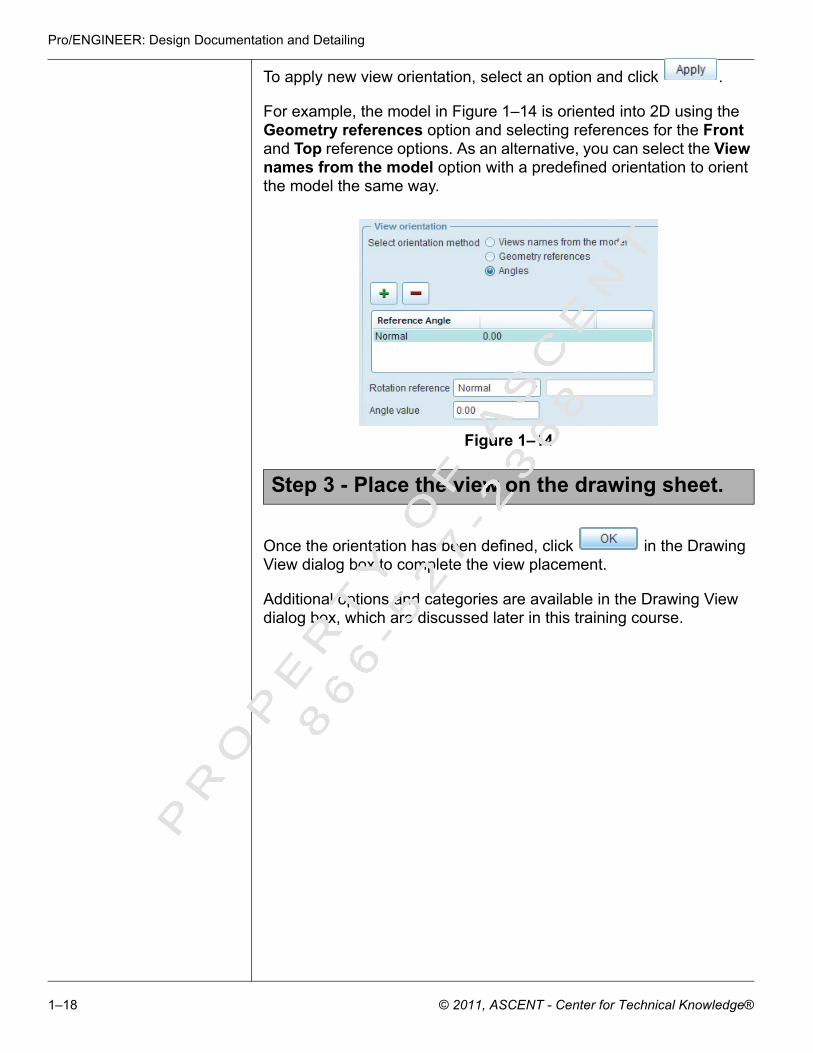
To apply new view orientation, select an option and click .
For example, the model in Figure 1–14 is oriented into 2D using the Geometry references option and selecting references for the Front and Top reference options. As an alternative, you can select the View names from the model option with a predefined orientation to orient the model the same way.
Figure 1–14
Once the orientation has been defined, click in the Drawing View dialog box to complete the view placement.
Additional options and categories are available in the Drawing View dialog box, which are discussed later in this training course.
Step 3 - Place the view on the drawing sheet.
PR
OP
ER
TY
OF
AS
CE
NT
86
6- 5
27
- 23
68
1–18 © 2011, ASCENT - Center for Technical Knowledge®

Views
1.5 Place Additional Views
Drawings usually consist of multiple views to accurately represent the drawing model.
Complete the following steps to place additional views in a drawing:
1. Select the Layout tab.
1. Start the creation of the view.
2. Place the view on the drawing sheet.
3. Complete the creation of the drawing view.
The Layout tab only shows the commands relevant to that function. This tab must be active to create and modify views.
Once a General view has been added to the drawing, you can create additional General views or other types of views that reference the General view. The view icons are found in the Layout tab in the Model Views group, as shown in Figure 1–15.
Figure 1–15
The additional view types are described in Table 1–3
Step 1 - Select the Layout tab.
Step 2 - Start the creation of the view.
Additional Views in the flyout.
PR
OP
ER
TY
OF
AS
CE
NT
86
6- 5
27
- 23
68
© 2011, ASCENT - Center for Technical Knowledge® 1–19

Pro/ENGINEER: Design Documentation and Detailing
Table 1–3
Option Description
General This option creates an independent view of a model. The orientation of the general view is determined by using the View Type category in the Drawing View dialog box. It is possible to place several general views on a drawing, as shown in Figure 1–16.
Figure 1–16
Projection This option projects a view off an existing view. This creates orthogonal views, such as top, bottom, right, or left. A projection view maintains the scale of its parent view as shown in Figure 1–17.
Figure 1–17
General View General (Oriented) View
General View (Parent) Projection View
PR
OP
ER
TY
OF
AS
CE
NT
86
6- 5
27
- 23
68
1–20 © 2011, ASCENT - Center for Technical Knowledge®

Views
Auxiliary This option projects a view normal to a datum plane, edge, or axis of an existing view. This type of view can be used to see the actual size and form off of an angled surface. Auxiliary views can be created by referencing a datum plane, an edge or an axis of any other type of view as shown in Figure 1–18.
Figure 1–18
Detailed This option creates a scaled view focusing on a specific area of an existing view. The detailed view is created by sketching a spline on the parent view that encloses the area to be represented. To complete the view, assign a name, boundary type and note location. The detailed view is automatically labeled with its scale value and view name. Orientation of this view corresponds to the parent view as shown in Figure 1–19.
Figure 1–19
Option Description
General View (Parent)
Auxiliary Viewprojected normalto a selected edge.
Auxiliary View (Child)
General View(Parent View)
Detailed View
PR
OP
ER
TY
OF
AS
CE
NT
86
6- 5
27
- 23
68
© 2011, ASCENT - Center for Technical Knowledge® 1–21

Pro/ENGINEER: Design Documentation and Detailing
The methods for creating a new view vary depending on the type of view that is required. The methods include the following:
Revolved This option creates a planar area cross-section that is revolved 90° around the projection of the cutting plane as shown in Figure 1–20. Revolved views can be translated in the projection direction.
Figure 1–20
Copy & Align
This option creates a duplicate of an existing Partial or Detailed view. A new boundary spline can be sketched and the view is aligned to the parent view as shown in Figure 1–21. The Copy & Align view maintains the same scale as its parent view.
Figure 1–21
Option Description
Revolved View
General View(Parent View)
Datum plane used to create planar area cross-section for Revolved View.
Detailed View(Parent View)
Copy & Align View
PR
OP
ER
TY
OF
AS
CE
NT
86
6- 5
27
- 23
68
1–22 © 2011, ASCENT - Center for Technical Knowledge®

Views
Drawings created using a template could already contain certain views. Additional views can be added at any time.
• To create an additional General view, right-click and select Insert General View and place the view (explained in Section 1.4). As an
alternative, you can click in the Layout tab.• To create a Projected view, right-click on the parent view and
select Insert Projection View or click in the Layout tab.
• If a parent view is pre-selected, only a Projection view can be created. To create a Detailed, Auxiliary, or Revolved view, you must clear all views and click the appropriate icon in the Model Views group from the Layout tab and then access these options.
Visibility area is a category that can be customized for a drawing view. This is discussed later in this training course.
• To create a Copy and Align view, pre-select a Detailed view or a
partial visibility area view and click in the Model Views group from the Layout tab. This view type is not available unless a Detailed view or a partial visibility area view has been created in the drawing.
To obtain information about a view, you can click in the Model Views group from the Layout tab and select a view. An information window appears, as shown in Figure 1–22.
Figure 1–22
PR
OP
ER
TY
OF
AS
CE
NT
86
6- 5
27
- 23
68
© 2011, ASCENT - Center for Technical Knowledge® 1–23

Pro/ENGINEER: Design Documentation and Detailing
In general, views are placed using the left mouse button. Note the following additional information for placing specific view types:
• General views are placed using the left mouse button. Initially, the view is placed in its default orientation; however, it can be oriented into 2D using any of the techniques discussed in Section 1.4.
• Projection views are placed using the left mouse button. They can only be placed horizontally or vertically relative to the parent view.
• Detailed views focus on a specific area; therefore, you must first select a point on an existing view. This point represents the centerpoint for the new view. Once selected, sketch a spline around this point to define the extent (boundary) of the view. To complete the spline, press the middle mouse button. Once the spline is complete, place the view using the left mouse button.
• Auxiliary views first require the selection of an edge, axis, or datum plane to represent the front surface of the new view. Once selected, use the left mouse button to place the view.
• Revolved views require the selection of a parent view followed by placement using the left mouse button. Once selected, the Drawing View dialog box appears. You can select the cross-section to be referenced or create a new one.
For many of the view types, the drawing view placement is complete upon placement. However, for General and Revolved views that use
the Drawing View dialog box, you must click to complete the view placement.
Additional options and categories that are available in the Drawing View dialog box are discussed later in this training course.
Step 3 - Place the view on the drawing sheet.
Step 4 - Complete the creation of the drawing view.
PR
OP
ER
TY
OF
AS
CE
NT
86
6- 5
27
- 23
68
1–24 © 2011, ASCENT - Center for Technical Knowledge®

Views
1.6 Modify View Properties
All except General and Revolved views are placed without accessing the Drawing Views dialog box. To further refine any views that do not access this dialog box, you can modify the view properties. So far, you have learned about the View Type category. The remaining categories in the Drawing View dialog box can also be used.
Complete the following steps to modify view properties:
1. Select the Layout tab.
2. Open the Drawing View dialog box.
3. Modify the view properties.
4. Complete the modification of the drawing view
The Layout tab only shows the commands relevant to that function. This tab must be active to modify views.
Use one of the following techniques to open the Drawing View dialog box, if it is not already open:
• Double-click on the view that you are modifying.• Select the view that you are modifying, right-click, and select
Properties.
To modify a view property, you must select a category in the left column of the Drawing View dialog box. Once selected, the dialog box updates and displays the available options for the selected category.
Step 1 - Select the Layout tab.
Step 2 - Open the Drawing View dialog box.
Step 3 - Modify the view properties.PR
OP
ER
TY
OF
AS
CE
NT
86
6- 5
27
- 23
68
© 2011, ASCENT - Center for Technical Knowledge® 1–25

Pro/ENGINEER: Design Documentation and Detailing
You learn about the following view property categories:
• Visible Area• Scale• Sections
The remaining categories are discussed in later chapters.
Visible Area By default, views are created so that the entire model is displayed. You can customize how much of the model to show in a view using the Visible Area category. Once the Visible Area category is selected, the dialog box appears as shown in Figure 1–23.
Figure 1–23
The Visible area options can be selected in the View Visibility pull-down menu. They are described in Table 1–4.
Table 1–4
Option Description
Full View
Displays a view of the entire model as shown in Figure 1–24. This is the default option.
Figure 1–24
PR
OP
ER
TY
OF
AS
CE
NT
86
6- 5
27
- 23
68
1–26 © 2011, ASCENT - Center for Technical Knowledge®

Views
Half View
Displays a view of the model about a line of symmetry as shown in Figure 1–25. The cutting plane used to define the half view can be a planar surface or a datum plane. This option is available for Projection, Auxiliary, and General views.
Figure 1–25
Partial View
Displays a view focused on a specific location on the model. Bounding entities define the geometry that is represented as shown in Figure 1–26. This option is available for Projection, Auxiliary, General, and Revolved views.
Figure 1–26
Broken View
Displays a view in which break lines define sections to be removed. Break lines can be horizontal and/or vertical as shown in Figure 1–27. This option is available for Projection and General views. You cannot break a horizontally projected view horizontally and you cannot break a vertically projected view vertically.
Figure 1–27
Option Description
PR
OP
ER
TY
OF
AS
CE
NT
86
6- 5
27
- 23
68
© 2011, ASCENT - Center for Technical Knowledge® 1–27

Pro/ENGINEER: Design Documentation and Detailing
Scale The Scale category in the Drawing View dialog box enables you to assign scales to General and Detailed views that are independent of the drawing scale. The scale for all other views in the drawing are determined by the parent view. Figure 1–28 shows the Scale category options in the Drawing View dialog box.
Figure 1–28
By default, views are created using the same scale that was assigned to the sheet (Default scale for sheet). Any changes made to the sheet scale updates these views. The Custom scale option enables you to assign an independent scale. Once assigned, the view scale is located directly under the view, as shown in Figure 1–29.
Figure 1–29
View scaleDrawing scale
PR
OP
ER
TY
OF
AS
CE
NT
86
6- 5
27
- 23
68
1–28 © 2011, ASCENT - Center for Technical Knowledge®

Views
The Perspective option enables you to change the viewing distance and diameter parameters of a General perspective view. The viewing distance is the distance (in model units) between the object and the viewer.The viewing diameter determines the actual size of the view based on drawing units. Figure 1–30 shows a model with different viewing distance parameter values.
Figure 1–30
Sections By default, a view is created with no sectioning. To create a cross-section view, select the Sections category in the Drawing View dialog box and select the 2D cross-section option. The dialog box appears as shown in Figure 1–31.
Figure 1–31
Viewing Distance=300 inches Viewing Distance=3000 inches
Viewing Distance=50 inches Viewing Distance=150 inches
PR
OP
ER
TY
OF
AS
CE
NT
86
6- 5
27
- 23
68
© 2011, ASCENT - Center for Technical Knowledge® 1–29

Pro/ENGINEER: Design Documentation and Detailing
2D Cross-Sections
Click to assign a cross-section to the view. The dialog box updates as shown in Figure 1–32. You can select the section name in the Name pull-down menu or use the Create New option in this menu to create a new section. The options for creating a new section are the same as in Part or Assembly mode.
For simplicity, create and save your section in the model, then open and place them in your drawing.
Figure 1–32
The edges that are displayed in the cross-section view can be customized by selecting an edge visibility method. The Total option creates a cross-section that displays all edges that are behind the cutting plane, as shown on the left side of Figure 1–33. The Area option creates a cross-section that displays only the material within the cutting plane, as shown on the right side of Figure 1–33. Edges behind the cutting plane are not visible.
Figure 1–33
Total model edge visibility Area model edge visibility
PR
OP
ER
TY
OF
AS
CE
NT
86
6- 5
27
- 23
68
1–30 © 2011, ASCENT - Center for Technical Knowledge®

Views
Once the cross-section has been selected, you can select an option in the Sectioned Area pull-down menu. The options are described in Table 1–5.
Table 1–5
Option Description
Full Displays the cross-section on the entire view (default option) as shown in Figure 1–34.
Figure 1–34
Half Displays the cross-section on one side of a boundary plane as shown in Figure 1–35. A datum plane is selected as the boundary for the cross-section. The material on the opposite side of the datum plane remains solid.
Figure 1–35
Referenced Datum Plane
PR
OP
ER
TY
OF
AS
CE
NT
86
6- 5
27
- 23
68
© 2011, ASCENT - Center for Technical Knowledge® 1–31

Pro/ENGINEER: Design Documentation and Detailing
Local Displays the cross-section focusing on a specific area(s). A sketched spline defines the boundary of the local view. The material outside the boundary remains solid as shown in Figure 1–36.
Figure 1–36
Full (Align) This option creates an area cross-section through the cutting planes of an offset cross-section until parallel to the screen. The planes are unfolded about an existing axis in the view as shown in Figure 1–37.
Figure 1–37
Full (Unfold) This option creates an area cross-section where the cutting planes of an offset cross-section unfold until parallel to the screen. The planes are unfolded about the seams of the offset cutting line as shown in Figure 1–38.
Figure 1–38
Option Description
Referenced Datum Axis
Unfold Seams
PR
OP
ER
TY
OF
AS
CE
NT
86
6- 5
27
- 23
68
1–32 © 2011, ASCENT - Center for Technical Knowledge®

Views
Once the Sectioned Area option has been selected, scroll to the right to access the remaining options for defining the section. These options are shown in Figure 1–39.
Figure 1–39
Once a section view has been created, cross-section arrows can be added by right-clicking on the sectioned view and then selecting Add Arrows or by clicking
.
The Arrow Display column enables you to add cross-section arrows to a view, as shown in Figure 1–40. To place the arrows, select this cell and select the view to place the arrows.
To clear the arrows from the display, right-click on the reference view that was assigned and select Remove.
Figure 1–40
The Reference and Boundary columns are only available if you have selected a local cross-section. They enable you to define the center point for the breakout and its defining spline.
PR
OP
ER
TY
OF
AS
CE
NT
86
6- 5
27
- 23
68
© 2011, ASCENT - Center for Technical Knowledge® 1–33

Pro/ENGINEER: Design Documentation and Detailing
Multiple 2D Cross-Sections
Multiple cross-sections can be assigned to a view by clicking to define another cross-section. Creating multiple cross-sections in one view can help reduce the number of views on a drawing sheet. For example, Figure 1–41 shows a view that has two cross-sections; one is set as Full and one as Local. To remove a cross-section from the
view, select it and use .
Figure 1–41
Single Part Surface
A view to which the Single part surface option is applied cannot be converted back to a normal view.
The Single part surface option in the Section options section of the dialog box provides an alternative to selecting or creating a cross-section. This option enables you to create a view of a single surface by projecting from the solid model surface or a datum quilt. Pro/ENGINEER deletes all other geometry, as shown in Figure 1–42. This option is not available for Detailed views.
Figure 1–42
Selected surface
Single part surface sectioned view
PR
OP
ER
TY
OF
AS
CE
NT
86
6- 5
27
- 23
68
1–34 © 2011, ASCENT - Center for Technical Knowledge®

Views
When you create a cross-section in Part mode or Assembly mode, the system automatically checks to see if the parts intersected by the cross-section have assigned materials. If the material name matches the name of the saved cross-hatching pattern file (e.g., copper.xch), the cross-hatching pattern is automatically applied. The pro_crosshatch_dir config.pro option is used to point to a directory containing user-defined cross-hatching pattern files.
In Figure 1–43, the assembly drawing contains a section view. The materials assigned to the two components (i.e., aluminum and steel) match the names of saved cross-hatching files (i.e., aluminum.xch and steel.xch). When the section view was created and placed, these cross-hatching patterns were automatically applied.
Figure 1–43
Cross-hatching
• You can hatch or fill flat surfaces by right-clicking on them and selecting Hatch or Fill.
• You can use the X-Area option on the MOD XHATCH menu to show or hide areas of component sections, as shown in Figure 1–44.
To access the MOD XHATCH menu, right-click on the crosshatch/fill and select Properties.
Figure 1–44
PR
OP
ER
TY
OF
AS
CE
NT
86
6- 5
27
- 23
68
© 2011, ASCENT - Center for Technical Knowledge® 1–35
Pro/ENGINEER: Design Documentation and Detailing
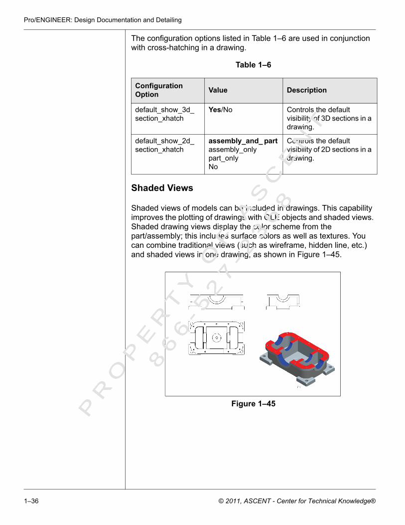
The configuration options listed in Table 1–6 are used in conjunction with cross-hatching in a drawing.
Table 1–6
Shaded Views
Shaded views of models can be included in drawings. This capability improves the plotting of drawings with OLE objects and shaded views. Shaded drawing views display the color scheme from the part/assembly; this includes surface colors as well as textures. You can combine traditional views (such as wireframe, hidden line, etc.) and shaded views in one drawing, as shown in Figure 1–45.
Figure 1–45
Configuration Option Value Description
default_show_3d_section_xhatch
Yes/No Controls the default visibility of 3D sections in a drawing.
default_show_2d_section_xhatch
assembly_and_ part assembly_onlypart_onlyNo
Controls the default visibility of 2D sections in a drawing.
PR
OP
ER
TY
OF
AS
CE
NT
86
6- 5
27
- 23
68
1–36 © 2011, ASCENT - Center for Technical Knowledge®

Views
You define a view as shaded in the View Display category of the Drawing View properties dialog box. Select Shading in the Display style pull-down menu, as shown in Figure 1–46.
Figure 1–46
Displaying edges in shaded views
By default, edges are not displayed in the shaded view. You can display them by setting the show_shaded_edges configuration option to Yes. The model with edges displayed is shown in Figure 1–47.
The edges are displayed in all shaded views in the drawing.
Figure 1–47
PR
OP
ER
TY
OF
AS
CE
NT
86
6- 5
27
- 23
68
© 2011, ASCENT - Center for Technical Knowledge® 1–37
Pro/ENGINEER: Design Documentation and Detailing
To complete the modification to the drawing view, click in the Drawing View dialog box.
Step 4 - Complete the modification of the drawing view
PR
OP
ER
TY
OF
AS
CE
NT
86
6- 5
27
- 23
68
1–38 © 2011, ASCENT - Center for Technical Knowledge®

Views
1.7 Drawing Environment Options
EnvironmentDialog Box
The Environment dialog box controls the display and default actions of your Pro/ENGINEER session. Select Tools > Environment to access the Environment dialog box, as shown in Figure 1–48.
Figure 1–48
PR
OP
ER
TY
OF
AS
CE
NT
86
6- 5
27
- 23
68
© 2011, ASCENT - Center for Technical Knowledge® 1–39

Pro/ENGINEER: Design Documentation and Detailing
Many of the environment option values can be globally controlled in the configuration file (e.g., display_planes enables you to define whether by default datum planes are displayed or not when the model is originally opened).
Many options in the Environment dialog box enable you to control default settings in your drawing. These include the following:
• The Snap Lines option enables you to turn snap lines On or Off in your drawing.
• The Snap to Grid option enables you to snap your drawing views to a grid line to align selected views.
• The Snap to Snap Lines option enables you to locate dimensions, notes, geometric tolerances, and surface finishes.
• The Highlight Erased Views option enables you to easily identify the view outline of erased views.
• The Lock View Movement option enables you to automatically lock views to prevent them from being moved. Locking must be disabled to move a view.
Drawing SetupFile
The drawing setup file is a file that gets stored with each drawing and controls certain characteristics of the drawing. For example, the drawing setup file values determine items such as projection type, view scale format, drawing units, dimension, and note text height.
All drawing setup file options can be reviewed using Pro/HELP. Refer to Appendix B for a description on how to use these options.
To access the drawing setup file, select File > Drawing Options. The Options dialog box appears as shown in Figure 1–49.
Figure 1–49
PR
OP
ER
TY
OF
AS
CE
NT
86
6- 5
27
- 23
68
1–40 © 2011, ASCENT - Center for Technical Knowledge®

Views
Drawing setup files are saved with a .dtl extension. The drawing_setup_file configuration file option enables you to specify a directory for storing all pre-defined company setup files.
Every Pro/ENGINEER drawing assigns default values to these setup file options. These values can be modified and saved for use in the same or other drawings. To save a drawing setup file for use in
another drawing, click . To open a pre-defined setup, click and select the file.
Config.pro File The config.pro is a configuration file that controls environment settings (e.g., setup file, drawing file editor) in Pro/ENGINEER. Select Tools > Options to access the config.pro file. The Options dialog box appears as shown in Figure 1–50.
Select the Show only options loaded from file option to show the user-defined options. Clear this option to show all options.
Figure 1–50
PR
OP
ER
TY
OF
AS
CE
NT
86
6- 5
27
- 23
68
© 2011, ASCENT - Center for Technical Knowledge® 1–41
Pro/ENGINEER: Design Documentation and Detailing
All configuration file options can be reviewed using Pro/HELP. Refer to Appendix B for a description on how to use Pro/HELP.
Many of the configuration file options are specific to Drawing mode. To access the specific drawing model options, select By Category in the Sort pull-down menu and scroll down to the Drawing list. All options in this section pertain to Drawing mode.
Unlike the drawing setup file, the config.pro is not automatically saved and stored with the drawing. Once changes are made, you must
explicitly save these changes by clicking . These changes are stored to the current configuration file.
Pro/ENGINEER reads the configuration file from several locations: the /loadpoint/text directory, the user’s home directory, and the startup directory. Additional configuration files can be stored in other locations, but they must be explicitly loaded to affect the drawing. To
open a config.pro, click and select the file.
PR
OP
ER
TY
OF
AS
CE
NT
86
6- 5
27
- 23
68
1–42 © 2011, ASCENT - Center for Technical Knowledge®

Views
Exercise 1a Create a New Drawing
In this exercise, you create drawing views from a Pro/ENGINEER solid part. The drawing model is shown in Figure 1–51.
Figure 1–51
Goal After you complete this exercise, you will be able to:
Create a new drawingAssign a model to the drawingSelect the sheet sizePlace views on the drawingModify the drawing scale
Task 1 - Create a new drawing and select the format and sheet size.
1. Click in the toolbar to create a new drawing. The New dialog box appears.
2. Select the Drawing option.
3. Enter [support] for the name.
PR
OP
ER
TY
OF
AS
CE
NT
86
6- 5
27
- 23
68
© 2011, ASCENT - Center for Technical Knowledge® 1–43

Pro/ENGINEER: Design Documentation and Detailing
4. Clear the Use Default Template option to create an empty drawing. The New dialog box appears as shown in Figure 1–52.
Figure 1–52
5. Click . The New Drawing dialog box appears.
6. Click in the Default Model section of the New Drawing dialog box.
7. Select support.prt in the current working directory and click
.
8. Select the Empty option in the Specify Template section.
PR
OP
ER
TY
OF
AS
CE
NT
86
6- 5
27
- 23
68
1–44 © 2011, ASCENT - Center for Technical Knowledge®

Views
9. Select A in the Standard Size pull-down menu. The New Drawing dialog box appears as shown in Figure 1–53.
Figure 1–53
10.Click to create the drawing. The Drawing mode user- interface appears.
Task 2 - Define the drawing’s projection type.
1. Select File > Drawing Options in the FILE PROPERTIES menu. The Options dialog box appears.
2. Select By Category in the Sort pull-down menu.
PR
OP
ER
TY
OF
AS
CE
NT
86
6- 5
27
- 23
68
© 2011, ASCENT - Center for Technical Knowledge® 1–45

Pro/ENGINEER: Design Documentation and Detailing
3. Select the projection_type option and ensure that it is set to third_angle. This is the default option. The Options dialog box appears as shown in Figure 1–54.
Figure 1–54
4. Close the Options dialog box.
Task 3 - Place a General view in the default orientation.
You can also right-click and select Insert General View.
1. Click from the flyout menu at the top.
2. Ensure the Layout tab is active.
3. Click in the Model Views group.
PR
OP
ER
TY
OF
AS
CE
NT
86
6- 5
27
- 23
68
1–46 © 2011, ASCENT - Center for Technical Knowledge®

Views
4. Select the top right corner of the drawing sheet to define the centerpoint for the drawing view. The Drawing View dialog box appears as shown in Figure 1–55.
Figure 1–55
5. Select Default Orientation in the Model view names section and
click . The drawing model appears as shown in Figure 1–56 in its default orientation.
Figure 1–56
PR
OP
ER
TY
OF
AS
CE
NT
86
6- 5
27
- 23
68
© 2011, ASCENT - Center for Technical Knowledge® 1–47

Pro/ENGINEER: Design Documentation and Detailing
Task 4 - Place a General view.
1. Click in the Model Views group to create a new General view.
2. Select the bottom left corner of the drawing sheet using the left mouse button to define the centerpoint for the drawing view.
3. Select Geometry references as the orientation method in the Drawing View dialog box.
4. Select Left in the pull-down menu for Reference 1. Select datum plane DTM1 in the Model Tree.
5. Select Top for Reference 2 and select datum plane DTM2 in the Model Tree. The Drawing View dialog box appears as shown in Figure 1–57.
While orienting a view, the drawing can be dynamically zoomed and panned. Dynamic rotation is not available in a 2D drawing.
Figure 1–57
PR
OP
ER
TY
OF
AS
CE
NT
86
6- 5
27
- 23
68
1–48 © 2011, ASCENT - Center for Technical Knowledge®

Views
6. If the view orientation corresponds to the view shown in
Figure 1–58, click . If not, click and reorient the model as necessary.
Figure 1–58
Task 5 - Modify the scale value for the drawing.
You can also double-click on the scale value to modify it.
1. Select Edit > Value.Select the scale value in the lower left corner of your drawing and modify it to [0.8]. The drawing and all of its views update, as shown in Figure 1–59.
Figure 1–59
View 1 (General)
Drawing scale
PR
OP
ER
TY
OF
AS
CE
NT
86
6- 5
27
- 23
68
© 2011, ASCENT - Center for Technical Knowledge® 1–49
Pro/ENGINEER: Design Documentation and Detailing
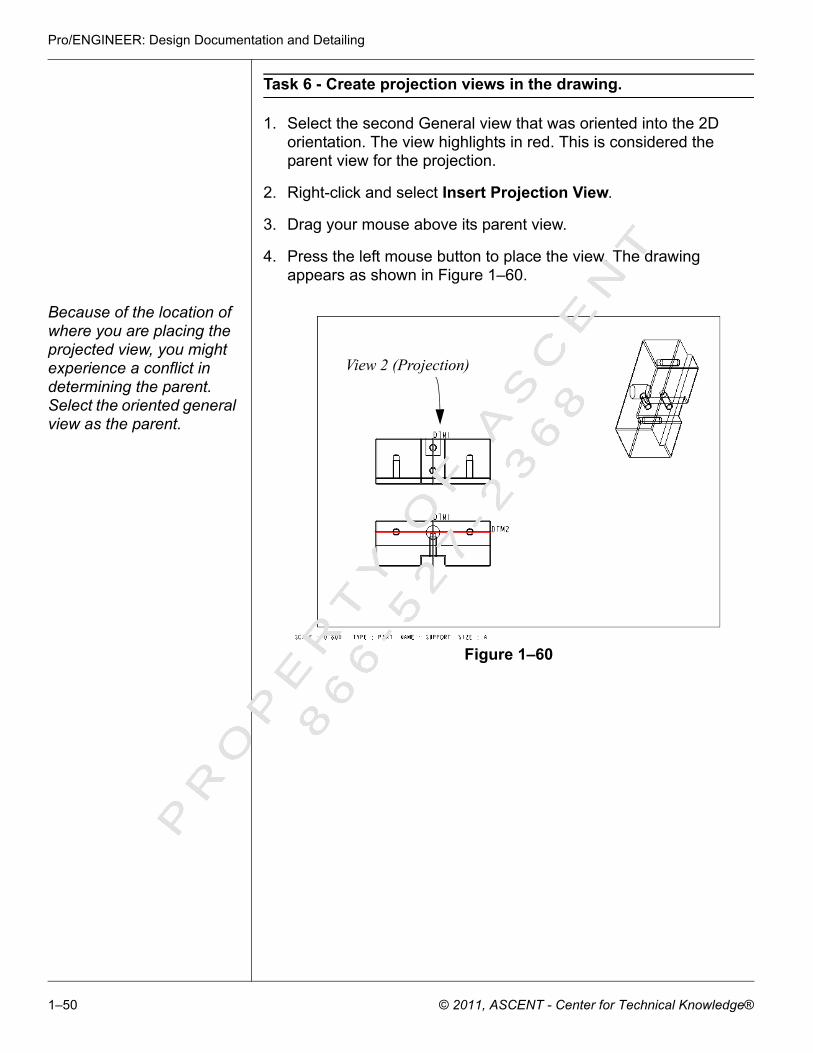
Task 6 - Create projection views in the drawing.
1. Select the second General view that was oriented into the 2D orientation. The view highlights in red. This is considered the parent view for the projection.
2. Right-click and select Insert Projection View.
3. Drag your mouse above its parent view.
4. Press the left mouse button to place the view. The drawing appears as shown in Figure 1–60.
Because of the location of where you are placing the projected view, you might experience a conflict in determining the parent. Select the oriented general view as the parent.
Figure 1–60
View 2 (Projection)
PR
OP
ER
TY
OF
AS
CE
NT
86
6- 5
27
- 23
68
1–50 © 2011, ASCENT - Center for Technical Knowledge®

Views
5. Repeat steps 1 and 4 to place a Projected view to the right of View 1. The drawing appears as shown in Figure 1–61.
Figure 1–61
6. Click to save the drawing and press <Enter>.
7. Select File > Close Window to close the window.
View 3 (Projection)
PR
OP
ER
TY
OF
AS
CE
NT
86
6- 5
27
- 23
68
© 2011, ASCENT - Center for Technical Knowledge® 1–51

Pro/ENGINEER: Design Documentation and Detailing
Exercise 1b Add a Drawing Format
In this exercise, you create drawing views from a Pro/ENGINEER solid part. You also assign a format to the drawing. The completed drawing is shown in Figure 1–62.
Figure 1–62
Goal After you complete this exercise, you will be able to:
Create a new drawingAdd a drawing formatOrient general views using saved viewsCreate a cross-sectional viewCreate detailed views
Task 1 - Create a new drawing.
1. Click in the toolbar to create a new drawing. The New dialog box appears.
2. Select the Drawing option.
3. Enter [base_plate] as the name of the drawing.
4. Clear the Use Default Template option to create an empty drawing.
PR
OP
ER
TY
OF
AS
CE
NT
86
6- 5
27
- 23
68
1–52 © 2011, ASCENT - Center for Technical Knowledge®

Views
5. Click . The New Drawing dialog box appears.
6. Click in the Default Model section of the New Drawing dialog box.
7. Select base_plate.prt in the current working directory and click
.
8. Select the Empty with format option.
9. Click in the Format section and double-click on generic_b_1.frm in the Formats directory. If the formats directory
is not listed in the Open dialog box, click to browse to the working directory and select the Format directory. The dialog box appears as shown in Figure 1–63.
Figure 1–63
10.Click to create the drawing.
Task 2 - Create a General view and orient it using a saved view.
1. Select the Layout tab.
PR
OP
ER
TY
OF
AS
CE
NT
86
6- 5
27
- 23
68
© 2011, ASCENT - Center for Technical Knowledge® 1–53

Pro/ENGINEER: Design Documentation and Detailing
2. With your mouse on the drawing sheet, right-click and select Insert General View.
3. Select the center of the drawing sheet as the centerpoint of the drawing view. The Drawing View dialog box appears.
4. Click BOTTOM in the Model view names section of the dialog box.
5. Click . The view automatically orients itself as shown in Figure 1–64.
Figure 1–64
6. Click to complete view placement and close the Drawing View dialog box.
Task 3 - Create an offset cross-section view in the drawing.
1. Select the General view that was just added to the drawing. The view frame highlights in red. This is considered the parent view for the projection.
2. Right-click and select Insert Projection View.
3. Drag your mouse to the right of the parent view.
4. Press the left mouse button to place the view.
PR
OP
ER
TY
OF
AS
CE
NT
86
6- 5
27
- 23
68
1–54 © 2011, ASCENT - Center for Technical Knowledge®

Views
5. Select the Projection view, right-click, and select Properties. The Drawing View dialog box appears. This dialog box enables you to further customize the drawing view so that it can be displayed as a section view.
6. Select the Sections category in the left frame of the Drawing View dialog box.
7. Select 2D cross-section to assign a cross-section to the view.
8. Keep the Total option selected in the Model edge visibility section to ensure that all edges are visible throughout the model, and not only for the 2D area of the section.
9. Click to add a section to the view. The Drawing View dialog box appears as shown in Figure 1–65.
Figure 1–65
It is recommended to create cross-sections in Part or Assembly mode, because the Sketcher environment is more flexible when working in these modes.
10.Select Offset > Both Sides > Single > Done in the XSEC CREATE menu.
PR
OP
ER
TY
OF
AS
CE
NT
86
6- 5
27
- 23
68
© 2011, ASCENT - Center for Technical Knowledge® 1–55

Pro/ENGINEER: Design Documentation and Detailing
11. Enter [A] at the prompt for cross-section name. The model appears in Part mode, as shown in Figure 1–66.
Figure 1–66
The cross-section sketch is created using Sketcher.
12.Select DTM2 as the sketching plane and flip the viewing direction.
13.Select Top and DTM3 as the reference plane. The model is oriented into 2D for sketching.
Click to display the datum axis.
14.Select Sketch > References from the part menu bar.
15.Select A_29 and A_20 and the top and bottom surfaces as additional sketcher references.
16.Select Sketch > Line > Line and sketch the cross-section shown in Figure 1–67.
To turn off the grid, select Sketch > Options and clear the Grid option in the Display tab.
Figure 1–67
17.Select Sketch > Constraints and add coincidence constraints between the vertical sketched lines and the axis references, as required.
18.Select Sketch > Done to complete the sketch.
19.Ensure that Full is displayed in the Sectioned Area for the cross-section. This ensures that the full view is sectioned.
PR
OP
ER
TY
OF
AS
CE
NT
86
6- 5
27
- 23
68
1–56 © 2011, ASCENT - Center for Technical Knowledge®

Views
20.Scroll to the right of the information for section A and select in the Arrow Display column, as shown in Figure 1–68.
Figure 1–68
21.Select the General view in the drawing as the view to display the
cutting plane arrows. Click . The drawing appears as shown in Figure 1–69.
Flip the cutting plane arrows to point to the left if necessary.
Figure 1–69
22.Click to complete view placement and close the Drawing View dialog box.
PR
OP
ER
TY
OF
AS
CE
NT
86
6- 5
27
- 23
68
© 2011, ASCENT - Center for Technical Knowledge® 1–57

Pro/ENGINEER: Design Documentation and Detailing
Task 4 - Create a Projection view in the drawing.
1. Create the Projection view shown in Figure 1–70.
Figure 1–70
Task 5 - Create Detailed views in the drawing
In this task, you create the detailed view shown in Figure 1–71.
Figure 1–71
You can also click
in the Model Views group from the Layout tab.
1. Ensure that nothing is selected. Right-click and select Insert Detailed View.
Second Projection view
PR
OP
ER
TY
OF
AS
CE
NT
86
6- 5
27
- 23
68
1–58 © 2011, ASCENT - Center for Technical Knowledge®

Views
2. To define a Detailed view, you must select a centerpoint in an existing view. This centerpoint must be on the model geometry. Select the second Projection view, as shown in Figure 1–72.
Figure 1–72
3. Sketch a closed spline around the centerpoint as shown in Figure 1–73 using the left mouse button. To complete the spline, press the middle mouse button. No entities should overlap.
Figure 1–73
4. Select to the left side of the second Projection view as the centerpoint for placing this Detailed view. The drawing view is automatically placed.
5. Select the new Detailed view, right-click, and select Properties. The Drawing View dialog box appears.
6. Change the View name to [X] and click .
7. Expand the Boundary type on parent view pull-down menu in the Detailed view properties section. These options enable you to change the shape that identifies the detailed area. Keep the Circle option selected.
8. Select the Scale category. The default value is 1.000. Notice how this value differs from the drawing scale. Maintain this value.
9. Click to complete the view.
Select here as the center for the detailed view.
PR
OP
ER
TY
OF
AS
CE
NT
86
6- 5
27
- 23
68
© 2011, ASCENT - Center for Technical Knowledge® 1–59

Pro/ENGINEER: Design Documentation and Detailing
10.The detailed view note is located by default. To change this location, select the Annotate tab. Select the note on the drawing and move it as necessary, as shown in Figure 1–74.
Figure 1–74
The drawing updates after the successful creation of the Detailed view, as shown in Figure 1–75.
Figure 1–75
11. Select the Layout tab.
Move the detailed note to this location
PR
OP
ER
TY
OF
AS
CE
NT
86
6- 5
27
- 23
68
1–60 © 2011, ASCENT - Center for Technical Knowledge®

Views
12.Repeat steps 1 to 10 to create the Detailed view called Y, shown in Figure 1–76.
Figure 1–76
Task 6 - Create another General view using the default orientation.
1. Place an additional General view in the upper right corner of the drawing. Create the view with an independent scale value of 0.2. Use the model’s default view to orient the model. The drawing updates as shown in Figure 1–77.
Figure 1–77
PR
OP
ER
TY
OF
AS
CE
NT
86
6- 5
27
- 23
68
© 2011, ASCENT - Center for Technical Knowledge® 1–61

Pro/ENGINEER: Design Documentation and Detailing
Task 7 - Move views as necessary.
1. By default, all views are locked. To unlock them, right-click in the view and clear Lock view movement, as shown in Figure 1–78.
Figure 1–78
2. Once unlocked, you can select the view and drag it on the drawing sheet as required.
3. Relock the views once moved (recommended).
4. Save the drawing and close the window.
Remove the check mark from this option
PR
OP
ER
TY
OF
AS
CE
NT
86
6- 5
27
- 23
68
1–62 © 2011, ASCENT - Center for Technical Knowledge®
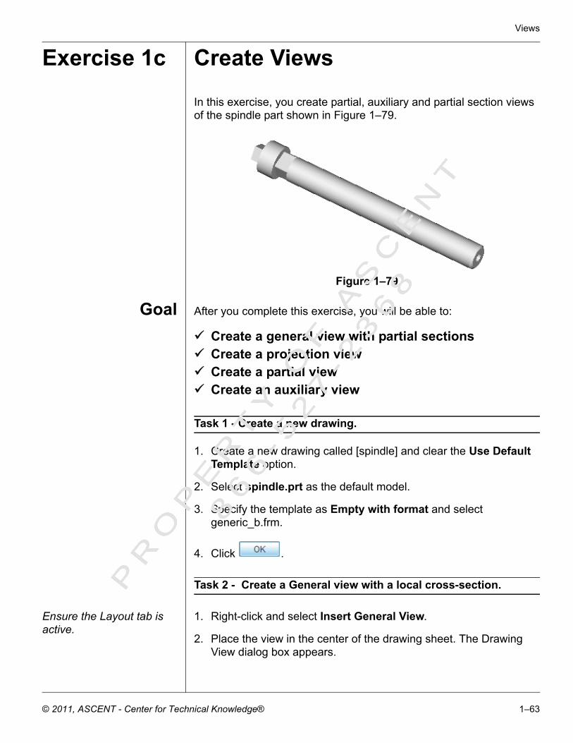
Views
Exercise 1c Create Views
In this exercise, you create partial, auxiliary and partial section views of the spindle part shown in Figure 1–79.
Figure 1–79
Goal After you complete this exercise, you will be able to:
Create a general view with partial sectionsCreate a projection viewCreate a partial viewCreate an auxiliary view
Task 1 - Create a new drawing.
1. Create a new drawing called [spindle] and clear the Use Default Template option.
2. Select spindle.prt as the default model.
3. Specify the template as Empty with format and select generic_b.frm.
4. Click .
Task 2 - Create a General view with a local cross-section.
Ensure the Layout tab is active.
1. Right-click and select Insert General View.
2. Place the view in the center of the drawing sheet. The Drawing View dialog box appears.
PR
OP
ER
TY
OF
AS
CE
NT
86
6- 5
27
- 23
68
© 2011, ASCENT - Center for Technical Knowledge® 1–63
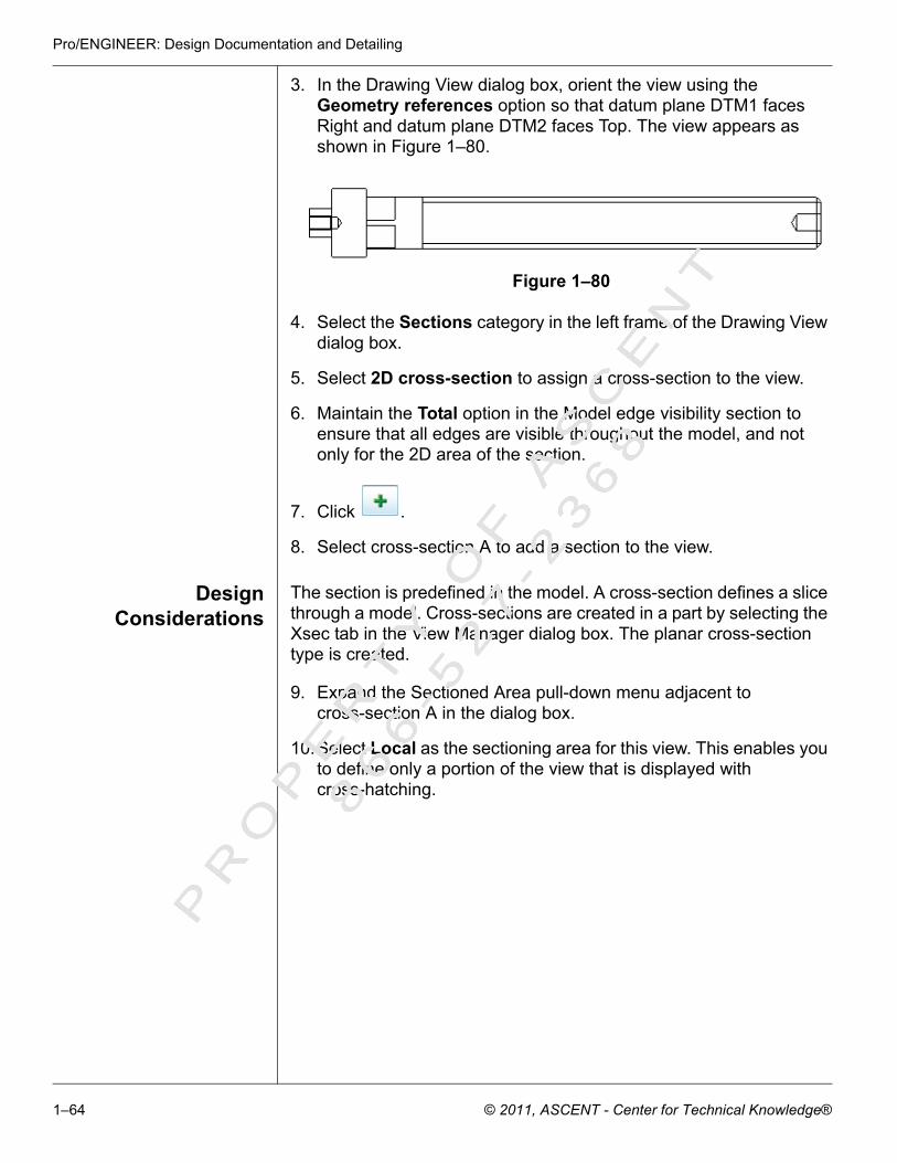
Pro/ENGINEER: Design Documentation and Detailing
3. In the Drawing View dialog box, orient the view using the Geometry references option so that datum plane DTM1 faces Right and datum plane DTM2 faces Top. The view appears as shown in Figure 1–80.
Figure 1–80
4. Select the Sections category in the left frame of the Drawing View dialog box.
5. Select 2D cross-section to assign a cross-section to the view.
6. Maintain the Total option in the Model edge visibility section to ensure that all edges are visible throughout the model, and not only for the 2D area of the section.
7. Click .
8. Select cross-section A to add a section to the view.
DesignConsiderations
The section is predefined in the model. A cross-section defines a slice through a model. Cross-sections are created in a part by selecting the Xsec tab in the View Manager dialog box. The planar cross-section type is created.
9. Expand the Sectioned Area pull-down menu adjacent to cross-section A in the dialog box.
10.Select Local as the sectioning area for this view. This enables you to define only a portion of the view that is displayed with cross-hatching.
PR
OP
ER
TY
OF
AS
CE
NT
86
6- 5
27
- 23
68
1–64 © 2011, ASCENT - Center for Technical Knowledge®

Views
11. Select the centerpoint for the Detailed view, as shown by the X in Figure 1–81. The reference appears in the Reference column.
Figure 1–81
12.Sketch a closed spline, as shown in Figure 1–81. This area defines the boundary of the local section.
13.Click . Select cross-section A to add another section to the view. This view is automatically assigned as Local. Keep this option selected.
14.Repeat Steps 12 and 13 to define the next local section on the opposite end of the spindle, as shown in Figure 1–82.
Figure 1–82
PR
OP
ER
TY
OF
AS
CE
NT
86
6- 5
27
- 23
68
© 2011, ASCENT - Center for Technical Knowledge® 1–65

Pro/ENGINEER: Design Documentation and Detailing
15.Click to apply the changes. The Drawing View dialog box appears as shown in Figure 1–83.
Figure 1–83
The partial sectioned view appears as shown in Figure 1–84.
Figure 1–84
16.Close the Drawing View dialog box to complete view creation.
PR
OP
ER
TY
OF
AS
CE
NT
86
6- 5
27
- 23
68
1–66 © 2011, ASCENT - Center for Technical Knowledge®

Views
Task 3 - Modify the scale of the drawing.
1. Modify the drawing scale to [1]. The drawing appears as shown in Figure 1–85.
Figure 1–85
Task 4 - Create Projection views in the drawing.
1. Place a Projected view to the left and right sides of the General view, as shown in Figure 1–86.
Figure 1–86
PR
OP
ER
TY
OF
AS
CE
NT
86
6- 5
27
- 23
68
© 2011, ASCENT - Center for Technical Knowledge® 1–67

Pro/ENGINEER: Design Documentation and Detailing
Task 5 - Create an Auxiliary partial view in the drawing.
1. Ensure that no views are currently selected in the drawing.
2. Right-click and select Insert Auxiliary View.
When an edge, axis, surface, or datum plane is used as a reference, it must be parallel to the projection direction.
3. Read the message line. As a reference for the projection, select the hidden edge of the view shown in Figure 1–87.
Figure 1–87
4. Select the centerpoint to place the view, as shown in Figure 1–88.
Figure 1–88
Select this hidden edge on the left projection view.
Select here to place the Auxiliary view.
PR
OP
ER
TY
OF
AS
CE
NT
86
6- 5
27
- 23
68
1–68 © 2011, ASCENT - Center for Technical Knowledge®

Views
The auxiliary view appears as shown in Figure 1–89.
Figure 1–89
5. Select the new Auxiliary view and double-click it. The Drawing View dialog box appears.
6. Select the Visible Area category in the left column.
7. Select Partial View in the View Visibility pull-down menu.
8. Create the boundary for the Partial Auxiliary view by selecting the centerpoint and sketching a closed spline for the Partial view, as shown in Figure 1–90.
Figure 1–90
Auxiliary view
PR
OP
ER
TY
OF
AS
CE
NT
86
6- 5
27
- 23
68
© 2011, ASCENT - Center for Technical Knowledge® 1–69

Pro/ENGINEER: Design Documentation and Detailing
9. Click to apply the changes. The Drawing View dialog box appears as shown in Figure 1–91.
Figure 1–91
10.Close the Drawing View dialog box. The partial view appears as shown in Figure 1–92.
Figure 1–92
Task 6 - Move the Auxiliary partial view.
1. If the views are locked, right-click and clear the check mark beside Lock View Movement to unlock them.
Partial Auxiliary view
PR
OP
ER
TY
OF
AS
CE
NT
86
6- 5
27
- 23
68
1–70 © 2011, ASCENT - Center for Technical Knowledge®

Views
2. Once unlocked, select the Auxiliary Partial view and drag the view to the location, as shown in Figure 1–93.
Figure 1–93
3. Relock the views once moved.
Task 7 - Add additional Detailed views in the drawing.
1. Create the detailed views named X and Y, as shown in Figure 1–94, using a scale of 2.0.
Figure 1–94
2. Save the drawing and close the working window.PR
OP
ER
TY
OF
AS
CE
NT
86
6- 5
27
- 23
68
© 2011, ASCENT - Center for Technical Knowledge® 1–71
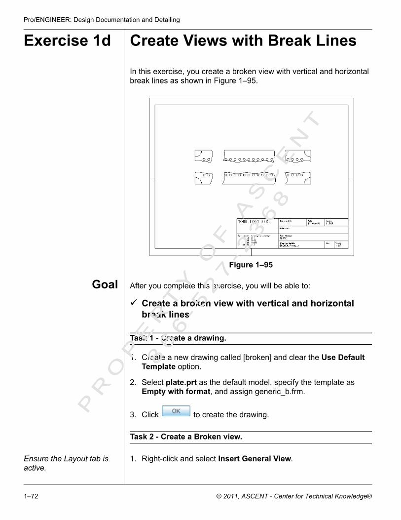
Pro/ENGINEER: Design Documentation and Detailing
Exercise 1d Create Views with Break Lines
In this exercise, you create a broken view with vertical and horizontal break lines as shown in Figure 1–95.
Figure 1–95
Goal After you complete this exercise, you will be able to:
Create a broken view with vertical and horizontal break lines
Task 1 - Create a drawing.
1. Create a new drawing called [broken] and clear the Use Default Template option.
2. Select plate.prt as the default model, specify the template as Empty with format, and assign generic_b.frm.
3. Click to create the drawing.
Task 2 - Create a Broken view.
Ensure the Layout tab is active.
1. Right-click and select Insert General View.
PR
OP
ER
TY
OF
AS
CE
NT
86
6- 5
27
- 23
68
1–72 © 2011, ASCENT - Center for Technical Knowledge®

Views
2. Place the view in the center of the drawing sheet.
3. Orient the view using the Views names from the model option, and select the FRONT saved view.
4. Apply the orientation changes.
Task 3 - Define the break locations.
1. In the Drawing View dialog box, select the Visible Area category in the left column.
2. Select Broken View in the View Visibility pull-down menu.
3. Click to add a breakout line to the view.
4. Select the vertical edge of the view in the location shown in Figure 1–96.
Figure 1–96
5. Move your mouse to the right side and select again to draw the first horizontal break line, as shown in Figure 1–97.
Figure 1–97
Select the vertical edge in this location.
PR
OP
ER
TY
OF
AS
CE
NT
86
6- 5
27
- 23
68
© 2011, ASCENT - Center for Technical Knowledge® 1–73

Pro/ENGINEER: Design Documentation and Detailing
6. Select a second break line location, as shown in Figure 1–98.
Figure 1–98
A second horizontal break line appears as shown in Figure 1–99.
Figure 1–99
7. Scroll to the right of the horizontal break in the Drawing View dialog box.
Select the vertical edge in this location.
PR
OP
ER
TY
OF
AS
CE
NT
86
6- 5
27
- 23
68
1–74 © 2011, ASCENT - Center for Technical Knowledge®

Views
8. Select Sketch from the pull-down in the Break Line Style cell, as shown in Figure 1–100.
Figure 1–100
9. Sketch the spline shown in Figure 1–101 to represent the break line for the view. Press the middle mouse button to complete the spline.
Figure 1–101
PR
OP
ER
TY
OF
AS
CE
NT
86
6- 5
27
- 23
68
© 2011, ASCENT - Center for Technical Knowledge® 1–75

Pro/ENGINEER: Design Documentation and Detailing
The break lines appear as shown in Figure 1–102.
Figure 1–102
10.Click to add a second set of break lines to the view.
11. Place the break lines, as shown in Figure 1–103. Refer to steps 4 through 6 to review how to place a break line.
Figure 1–103
12.Scroll to the right of the horizontal break in the Drawing View dialog box.
13.Select Sketch in the Break Line Style pull-down menu. Sketch a spline vertically along the first vertical breakline.
PR
OP
ER
TY
OF
AS
CE
NT
86
6- 5
27
- 23
68
1–76 © 2011, ASCENT - Center for Technical Knowledge®
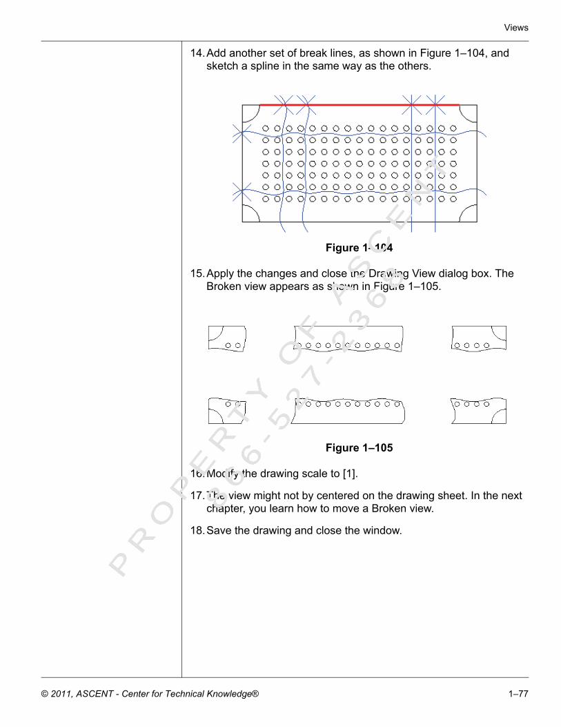
Views
14.Add another set of break lines, as shown in Figure 1–104, and sketch a spline in the same way as the others.
Figure 1–104
15.Apply the changes and close the Drawing View dialog box. The Broken view appears as shown in Figure 1–105.
Figure 1–105
16.Modify the drawing scale to [1].
17.The view might not by centered on the drawing sheet. In the next chapter, you learn how to move a Broken view.
18.Save the drawing and close the window.
PR
OP
ER
TY
OF
AS
CE
NT
86
6- 5
27
- 23
68
© 2011, ASCENT - Center for Technical Knowledge® 1–77

Pro/ENGINEER: Design Documentation and Detailing
Exercise 1e Create a Drawing
In this exercise, you create drawing views from a Pro/ENGINEER solid part. You also assign a format to the drawing. The drawing model is shown in Figure 1–106.
Figure 1–106
Goal After you complete this exercise, you will be able to:
Create a planar cross-section in partCreate a new drawingAdd a drawing formatOrient general views using saved viewsCreate a cross-sectional viewCreate detailed viewsTake specific measurements from a model
Task 1 - Open a part file.
1. Open screw.prt. The model appears as shown in Figure 1–107.
Figure 1–107
Task 2 - Create the first planar cross-sections.
1. Ensure that datum planes are displayed and that Annotation Elements (3D notes) are not displayed, as shown in Figure 1–108.
Figure 1–108
2. Click to open View Manager. Select the Xsec tab.
3. Create a new cross-section and enter [A] as its name.
PR
OP
ER
TY
OF
AS
CE
NT
86
6- 5
27
- 23
68
1–78 © 2011, ASCENT - Center for Technical Knowledge®

Views
4. Accept the defaults in the Menu Manager by selecting Done or clicking the middle mouse button.
5. Select datum plane D3. The cross-section is complete.
6. Double-click on cross-section A to make it active and to display it in the main window. One side of the cross-section is removed from the display.
7. Select Display > Visibility in the View Manager to see the cross-hatching for the section. The model is displayed as shown in Figure 1–109.
Figure 1–109
8. Right-click on the A cross-section in the View Manager and clear Visibility. Double-click on No cross-section to return the display back to normal.
Task 3 - Create the second planar cross-sections.
1. Create a new cross-section and enter [B] as its name.
2. Accept the defaults in the Menu Manager by selecting Done or clicking the middle mouse button.
3. Select datum plane B. The cross-section is complete.
4. Double-click on cross-section B to make it active and to display it in the main window. One side of the cross-section is removed from the display.
5. View the cross-hatching for the section by right-clicking on it and clicking Visibility. The model is displayed as shown in Figure 1–110.
Figure 1–110
PR
OP
ER
TY
OF
AS
CE
NT
86
6- 5
27
- 23
68
© 2011, ASCENT - Center for Technical Knowledge® 1–79

Pro/ENGINEER: Design Documentation and Detailing
6. Right-click on the cross-section and clear Visibility. Double-click on No cross-section to return the display back to normal.
Task 4 - Create the third planar cross-sections.
1. Create a new cross-section and enter [C] as its name.
2. Accept the defaults in the Menu Manager by selecting Done or clicking the middle mouse button.
3. Select datum plane C. The cross-section is complete.
4. Double-click on cross-section C to make it active and to display it in the main window. One side of the cross-section is removed from the display.
5. View the cross-hatching for the section by right-clicking on it and clicking Visibility. The model is displayed as shown in Figure 1–111.
Figure 1–111
6. Right-click on the cross-section and clear Visibility. Double-click on No cross-section to return the display back to normal.
7. Save the part and close the window.
Task 5 - Create a new drawing called screw.
1. Click in the toolbar to create a new drawing. The New dialog box appears.
2. Select the Drawing option.
3. Enter [screw] as the name of the drawing.
4. Clear the Use Default Template option to create an empty drawing.
PR
OP
ER
TY
OF
AS
CE
NT
86
6- 5
27
- 23
68
1–80 © 2011, ASCENT - Center for Technical Knowledge®

Views
5. Click . The New Drawing dialog box appears.
6. Click in the Default Model section of the New Drawing dialog box.
7. Select screw.prt in the current working directory and click
.
8. Select the Empty with format option.
9. Click in the Format section and double-click on generic_b.frm in the formats directory. If the formats directory is
not listed in the Open dialog box, click to browse to the working directory and then select the format directory. The dialog box appears as shown in Figure 1–112.
Figure 1–112
10.Click to create the drawing.
Task 6 - Create a Broken view and orient it using a saved view.
Ensure the Layout tab is active.
1. Right-click on the drawing sheet and select Insert General View.
PR
OP
ER
TY
OF
AS
CE
NT
86
6- 5
27
- 23
68
© 2011, ASCENT - Center for Technical Knowledge® 1–81

Pro/ENGINEER: Design Documentation and Detailing
2. Select the center of the drawing sheet as the centerpoint of the drawing view. The Drawing View dialog box appears.
3. Click FRONT in the Model view names section of the dialog box.
4. Click . The view automatically orients itself as shown in Figure 1–113.
Figure 1–113
5. Click to complete the view placement and close the Drawing View dialog box.
Task 7 - Modify the scale value for the drawing.
You can also double-click on the scale value to modify it.
1. Select Edit > Value.
PR
OP
ER
TY
OF
AS
CE
NT
86
6- 5
27
- 23
68
1–82 © 2011, ASCENT - Center for Technical Knowledge®
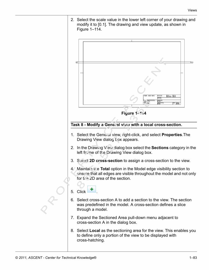
Views
2. Select the scale value in the lower left corner of your drawing and modify it to [0.1]. The drawing and view update, as shown in Figure 1–114.
Figure 1–114
Task 8 - Modify a General view with a local cross-section.
1. Select the General view, right-click, and select Properties.The Drawing View dialog box appears.
2. In the Drawing View dialog box select the Sections category in the left frame of the Drawing View dialog box.
3. Select 2D cross-section to assign a cross-section to the view.
4. Maintain the Total option in the Model edge visibility section to ensure that all edges are visible throughout the model and not only for the 2D area of the section.
5. Click .
6. Select cross-section A to add a section to the view. The section was predefined in the model. A cross-section defines a slice through a model.
7. Expand the Sectioned Area pull-down menu adjacent to cross-section A in the dialog box.
8. Select Local as the sectioning area for the view. This enables you to define only a portion of the view to be displayed with cross-hatching.
PR
OP
ER
TY
OF
AS
CE
NT
86
6- 5
27
- 23
68
© 2011, ASCENT - Center for Technical Knowledge® 1–83

Pro/ENGINEER: Design Documentation and Detailing
9. Select the centerpoint for the Detailed view, as shown by the X in Figure 1–115. The reference appears in the Reference column.
10.Sketch a closed spline, as shown in Figure 1–115. This area defines the boundary of the local section.
Figure 1–115
11. Click . Select cross-section A to add another section to the view. This view is automatically assigned as Local. Keep this option selected.
12.Define the next local section on the opposite end of the screw, as shown in Figure 1–116.
Figure 1–116
Task 9 - Define the break locations.
1. In the Drawing View dialog box, select the Visible Area category in the left column.
PR
OP
ER
TY
OF
AS
CE
NT
86
6- 5
27
- 23
68
1–84 © 2011, ASCENT - Center for Technical Knowledge®

Views
2. Select Broken View in the View Visibility pull-down menu.
3. Click to add a breakout line to the view.
4. Select the horizontal edge of the view in the location shown in Figure 1–117.
Figure 1–117
5. Move your mouse down and select again to draw the first vertical break line, as shown in Figure 1–118.
Figure 1–118
Select the horizontal edge in this location.
PR
OP
ER
TY
OF
AS
CE
NT
86
6- 5
27
- 23
68
© 2011, ASCENT - Center for Technical Knowledge® 1–85

Pro/ENGINEER: Design Documentation and Detailing
6. Select a second break line location, as shown in Figure 1–119.
Figure 1–119
A second vertical break line appears as shown in Figure 1–120.
Figure 1–120
7. Scroll across to show the Break Line Style column in the Drawing View dialog box.
Select the horizontal edge in this location.
PR
OP
ER
TY
OF
AS
CE
NT
86
6- 5
27
- 23
68
1–86 © 2011, ASCENT - Center for Technical Knowledge®

Views
8. Select Straight in the Break Line Style cell to access the pull-down menu and select Sketch. The Drawing View dialog box appears as shown in Figure 1–121.
Figure 1–121
9. Sketch the spline shown in Figure 1–122 to represent the break line for the view. Press the middle mouse button to complete the spline.
Figure 1–122
PR
OP
ER
TY
OF
AS
CE
NT
86
6- 5
27
- 23
68
© 2011, ASCENT - Center for Technical Knowledge® 1–87

Pro/ENGINEER: Design Documentation and Detailing
The break lines appear as shown in Figure 1–123.
Figure 1–123
10.Apply the changes and close the Drawing View dialog box. The Broken view appears as shown in Figure 1–124.
Figure 1–124
11. The view cannot by centered in the drawing sheet. In the next chapter, you learn how to move a Broken view.
Task 10 - Modify the scale value for the drawing.
You can also double-click on the scale value to modify it.
1. Select Edit > Value.
PR
OP
ER
TY
OF
AS
CE
NT
86
6- 5
27
- 23
68
1–88 © 2011, ASCENT - Center for Technical Knowledge®

Views
2. Select the scale value in the lower left corner of your drawing and modify it to [0.5]. The drawing and view update, as shown in Figure 1–125.
Figure 1–125
Task 11 - Create Projection views in the drawing.
1. Place a Projected view to the left and right sides of the General view with cross-sections B and C. The drawing appears as shown in Figure 1–126.
Figure 1–126
PR
OP
ER
TY
OF
AS
CE
NT
86
6- 5
27
- 23
68
© 2011, ASCENT - Center for Technical Knowledge® 1–89
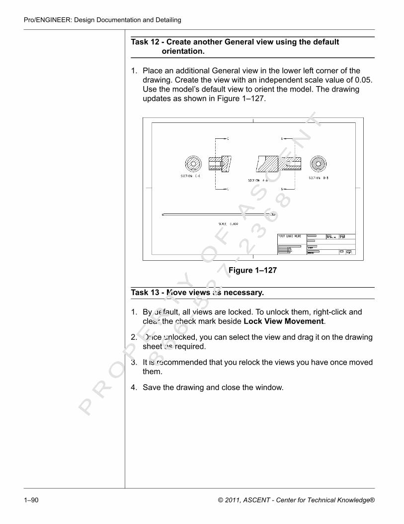
Pro/ENGINEER: Design Documentation and Detailing
Task 12 - Create another General view using the default orientation.
1. Place an additional General view in the lower left corner of the drawing. Create the view with an independent scale value of 0.05. Use the model’s default view to orient the model. The drawing updates as shown in Figure 1–127.
Figure 1–127
Task 13 - Move views as necessary.
1. By default, all views are locked. To unlock them, right-click and clear the check mark beside Lock View Movement.
2. Once unlocked, you can select the view and drag it on the drawing sheet as required.
3. It is recommended that you relock the views you have once moved them.
4. Save the drawing and close the window.
PR
OP
ER
TY
OF
AS
CE
NT
86
6- 5
27
- 23
68
1–90 © 2011, ASCENT - Center for Technical Knowledge®